EP3182558A1 - Flux shield having split structures and generator including the same - Google Patents
Flux shield having split structures and generator including the same Download PDFInfo
- Publication number
- EP3182558A1 EP3182558A1 EP16198935.5A EP16198935A EP3182558A1 EP 3182558 A1 EP3182558 A1 EP 3182558A1 EP 16198935 A EP16198935 A EP 16198935A EP 3182558 A1 EP3182558 A1 EP 3182558A1
- Authority
- EP
- European Patent Office
- Prior art keywords
- flux shield
- generator
- flux
- shield
- split
- Prior art date
- Legal status (The legal status is an assumption and is not a legal conclusion. Google has not performed a legal analysis and makes no representation as to the accuracy of the status listed.)
- Granted
Links
Images





Classifications
-
- H—ELECTRICITY
- H02—GENERATION; CONVERSION OR DISTRIBUTION OF ELECTRIC POWER
- H02K—DYNAMO-ELECTRIC MACHINES
- H02K11/00—Structural association of dynamo-electric machines with electric components or with devices for shielding, monitoring or protection
- H02K11/01—Structural association of dynamo-electric machines with electric components or with devices for shielding, monitoring or protection for shielding from electromagnetic fields, i.e. structural association with shields
- H02K11/014—Shields associated with stationary parts, e.g. stator cores
- H02K11/0141—Shields associated with casings, enclosures or brackets
-
- H—ELECTRICITY
- H02—GENERATION; CONVERSION OR DISTRIBUTION OF ELECTRIC POWER
- H02K—DYNAMO-ELECTRIC MACHINES
- H02K3/00—Details of windings
- H02K3/42—Means for preventing or reducing eddy-current losses in the winding heads, e.g. by shielding
Definitions
- the present disclosure relates to a flux shield and a generator including the same and, more particularly, to a flux shield including split structures and a generator including the same.
- FIG. 1 is a diagram showing a generator having flux shields for shielding a magnetic flux mounted thereon on both sides thereof
- FIG. 2 is a diagram showing one end portion of the generator from which a rotary rotor has been removed.
- FIG. 3 is a plan schematic diagram showing the flux shield of FIG. 2
- FIG. 4 is a diagram showing the state in which a magnetic flux is introduced form the outside to the inside of the generator.
- a large amount of a magnetic flux is generated from both ends of the generator.
- the generated magnetic flux is introduced from the outside to the inside of the generator (refers to the dotted arrows).
- the magnetic flux is saturated at both ends of the generator due to the introduced magnetic flux. Accordingly, in order to prevent the saturation of the magnetic flux from being generated at both ends of the generator, a step is formed at the end portion of a core or a magnetic flux shield plate is installed thereon.
- the magnetic flux shield plate according to a conventional technology is installed, it is fabricated to fully cover both ends of the generator. In this case, since the magnetic flux shield plates have to be fabricated in an integrated manner, the cost of production of the magnetic flux shield plate and the cost of materials thereof are increased.
- a flux shield 100 is mounted on both ends of the generator 10 and shields a magnetic flux introduced from the outside to the inside of the generator.
- the flux shield 100 may include two or more split structures spaced apart from each other at specific intervals.
- the flux shield may be formed to have a size and shape corresponding to both ends of a generator.
- the flux shield may have a circular shape formed to have the diameter of a length corresponding to the width of both ends of the generator.
- the split structure may include a radial point symmetry structure on the plane. Furthermore, the split structure may include a left and right symmetry structure or a top and bottom symmetry structure on the plane.
- the flux shield may include one or more step structures corresponding to a shape of both ends of a generator on which the flux shield is mounted, and may have split structures formed along the curved portions of the step structures.
- the flux shield may be made of copper or aluminum or a material including copper and aluminum.
- the interval between the split structures may be 1 to 100 mm.
- the flux shield may have a structure split into 2 to 12 pieces by the split structure.
- an embodiment of the present disclosure may provide a generator including the flux shields mounted on both ends of the generator and adapted to shield a magnetic flux from the outside to the inside of the generator.
- the flux shield of the generator according to an aspect of the present disclosure may have two or more split structures spaced apart from each other at specific intervals.
- the flux shield according to an embodiment of the present disclosure includes the two or more split structures spaced apart from each other at specific intervals. Accordingly, the flux shield which can be easily fabricated, can be easily assembled and managed, and can reduce the cost of production and assembly and management costs and a generator including the same can be provided.
- the flux shield according to an embodiment of the present disclosure can be fabricated to have split structures of various forms, such as a radial point symmetry structure, a left and right symmetry structure or a top and bottom symmetry structure. Accordingly, the flux shield can be easily fabricated compared to a flux shield according to a conventional technology, and thus the cost of production can be significantly reduced.
- the flux shield according to an embodiment of the present disclosure has the structure split into two or more pieces. Accordingly, a mounting and assembly task can be performed more easily compared to a conventional technology in mounting the flux shields on both ends of a generator.
- the flux shield according to an embodiment of the present disclosure can be easily fabricated compared to a flux shield according to a conventional technology because it includes one or more step structures corresponding to a shape of both ends of a generator and has the split structures formed along the curved portions of the step structures. Accordingly, the cost of production can be significantly reduced, and a mounting and assembly task can be performed more easily compared to a conventional technology in mounting the flux shields on both ends of a generator.
- the flux shield according to an embodiment of the present disclosure can be easily applied to generators of various specifications in addition to a generator of specific specifications because the interval between the split structures and the number of split pieces can be properly changed depending on the specifications of a generator and/or a designer's intention.
- the generator according to an embodiment of the present disclosure can significantly reduce the cost of production and production costs because it includes the flux shields according to an embodiment of the present disclosure.
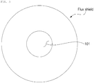
- FIG. 5 is a plan schematic diagram showing a flux shield according to an embodiment of the present disclosure.
- the flux shield 100 is mounted on both ends of the generator 10 (refer to FIG. 1 ) and shields a magnetic flux introduced from the outside to the inside of the generator.
- the flux shield 100 may include two or more split structures 110 (such as gaps or spaces between structures) spaced apart from each other at specific intervals "d.”
- the interval between the split structures may be a value in the range of 1 to 100 mm. If the interval between the split structures is less than 1 mm, a magnetic flux shield effect may be achieved, but a production cost reduction effect is very small. If the interval between the split structures is more than 100 mm, a target effect may not be achieved because the magnetic flux shield effect is significantly reduced.
- a shape on the plane of the flux shield 100 may have a size and shape corresponding to both ends of the generator 10, as shown in FIG. 5 .
- a shape on the plane of the flux shield 100 may be a circular shape having the diameter of a length corresponding to the width of both ends of the generator 10. If a shape of both ends of the generator 10 is a quadrangle, the flux shield 100 may also be fabricated to have a quadrangle having a shape and size corresponding to the quadrangle.
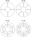
- FIGs. 6 are a plan schematic diagrams showing flux shields according to some embodiments of the present disclosure.
- a split structure of the flux shield 100 may include a radial point symmetry structure on a plane. Furthermore, a split structure of the flux shield 100 according to the present embodiment may include a left and right symmetry structure or a top and bottom symmetry structure on the plane.
- the flux shield 100 may have a structure split into 2 to 12 pieces by the split structures. If the flux shield 100 has a structure split into more than 12 pieces by the split structures, there may be increases in that the cost of production is further increased and the manufacturing time may be increased. Furthermore, if the split structure is a structure split into more than 12 pieces, additional time may be needed for a production assembly process is increased because a process of assembling the split structures by mounting them on both ends of the generator is complicated.
- a material forming the flux shield 100 according to the present embodiment is not specially limited to any material if the material can be mounted on both ends of the generator and can shield a magnetic flux introduced from the outside to the inside of the generator.
- the flux shield 100 may be made of copper or aluminum or a material including copper and aluminum.
- FIG. 7 is a perspective view showing the state in which only one end portion of the generator has been extracted and the shape of the end portion has been cut.
- the flux shield 100 may include one or more step structures 120 corresponding to a shape of both ends of the generator 10 on which the flux shield 100 is mounted.
- the split structure may be formed along the curved portion 121 of the step structure 120.
- a flux shield according to a conventional technology does not adopt a split structure in forming the above-described step structure, but is fabricated in an integrated manner. For this reason, the flux shield according to a conventional technology requires a very high level of a technology in its fabrication. As a result, there is a problem in that the cost of production rises.
- the flux shield 100 according to the present embodiment can be fabricated very easily because the split structure is formed along the curved portion 121 of the step structure 120. As a result, the cost of production can be reduced.
- the interval between the split structures formed along the curved portions 121 of the step structures 120 may be in the range of 1 to 100 mm.
- an embodiment of the present disclosure may provide a generator having the flux shields 100 according to the present embodiment mounted on both ends thereof.
- the flux shield 100 includes the structures and split structures corresponding to both ends of the generator. Accordingly, the flux shield 100 can be easily mounted and assembled into both ends of the generator.
- the generator according to the present embodiment includes the flux shield 100 which can be easily mounted and assembled. Accordingly, the time taken for a process of fabricating a generator can be significantly reduced.
- the flux shield according to an embodiment of the present disclosure includes the two or more split structures spaced apart from each other at specific intervals. Accordingly, the flux shield which can be easily fabricated, can be easily assembled and managed, and can reduce the cost of production and assembly and management costs and a generator including the same can be provided.
- the flux shield according to an embodiment of the present disclosure can be fabricated to have split structures of various forms, such as a radial point symmetry structure, a left and right symmetry structure or a top and bottom symmetry structure. Accordingly, the flux shield can be easily fabricated compared to a flux shield according to a conventional technology, and thus the cost of production can be significantly reduced.
- the flux shield according to an embodiment of the present disclosure has the structure split into two or more pieces. Accordingly, a mounting and assembly task can be performed more easily compared to a conventional technology in mounting the flux shields on both ends of a generator.
- the flux shield according to an embodiment of the present disclosure can be easily fabricated compared to a flux shield according to a conventional technology because it includes one or more step structures corresponding to a shape of both ends of a generator and has the split structures formed along the curved portions of the step structures. Accordingly, the cost of production can be significantly reduced, and a mounting and assembly task can be performed more easily compared to a conventional technology in mounting the flux shields on both ends of a generator.
- the flux shield according to an embodiment of the present disclosure can be easily applied to generators of various specifications in addition to a generator of specific specifications because the interval between the split structures and the number of split pieces can be properly changed depending on the specifications of a generator and/or a designer's intention.
- the generator according to an embodiment of the present disclosure can significantly reduce the cost of production and production costs because it includes the flux shields according to an embodiment of the present disclosure.
Landscapes
- Engineering & Computer Science (AREA)
- Power Engineering (AREA)
- Physics & Mathematics (AREA)
- Electromagnetism (AREA)
- Motor Or Generator Frames (AREA)
- Iron Core Of Rotating Electric Machines (AREA)
- Microelectronics & Electronic Packaging (AREA)
Abstract
Description
- The present disclosure relates to a flux shield and a generator including the same and, more particularly, to a flux shield including split structures and a generator including the same.
-
FIG. 1 is a diagram showing a generator having flux shields for shielding a magnetic flux mounted thereon on both sides thereof, andFIG. 2 is a diagram showing one end portion of the generator from which a rotary rotor has been removed. Furthermore,FIG. 3 is a plan schematic diagram showing the flux shield ofFIG. 2 , andFIG. 4 is a diagram showing the state in which a magnetic flux is introduced form the outside to the inside of the generator. - Referring to
FIGS. 1 to 4 , similar to a large amount of a magnetic flux is generated from both ends of a magnet, a large amount of a magnetic flux is generated from both ends of the generator. As shown inFIG. 4 , the generated magnetic flux is introduced from the outside to the inside of the generator (refers to the dotted arrows). The magnetic flux is saturated at both ends of the generator due to the introduced magnetic flux. Accordingly, in order to prevent the saturation of the magnetic flux from being generated at both ends of the generator, a step is formed at the end portion of a core or a magnetic flux shield plate is installed thereon. - If the magnetic flux shield plate according to a conventional technology is installed, it is fabricated to fully cover both ends of the generator. In this case, since the magnetic flux shield plates have to be fabricated in an integrated manner, the cost of production of the magnetic flux shield plate and the cost of materials thereof are increased.
- Furthermore, if both ends of the generator have a complicated structure, the cost of production is further increased.
- Accordingly, there is a need for a technology in which a magnetic flux shield plate can be fabricated at a low cost.
- A
flux shield 100 according to an aspect of the present disclosure is mounted on both ends of thegenerator 10 and shields a magnetic flux introduced from the outside to the inside of the generator. Theflux shield 100 may include two or more split structures spaced apart from each other at specific intervals. - In an embodiment of the present disclosure, the flux shield may be formed to have a size and shape corresponding to both ends of a generator.
- In this case, the flux shield may have a circular shape formed to have the diameter of a length corresponding to the width of both ends of the generator.
- In an embodiment of the present disclosure, the split structure may include a radial point symmetry structure on the plane. Furthermore, the split structure may include a left and right symmetry structure or a top and bottom symmetry structure on the plane.
- In some embodiments, the flux shield may include one or more step structures corresponding to a shape of both ends of a generator on which the flux shield is mounted, and may have split structures formed along the curved portions of the step structures.
- In an embodiment of the present disclosure, the flux shield may be made of copper or aluminum or a material including copper and aluminum.
- In an embodiment of the present disclosure, the interval between the split structures may be 1 to 100 mm.
- Furthermore, the flux shield may have a structure split into 2 to 12 pieces by the split structure.
- Furthermore, an embodiment of the present disclosure may provide a generator including the flux shields mounted on both ends of the generator and adapted to shield a magnetic flux from the outside to the inside of the generator. The flux shield of the generator according to an aspect of the present disclosure may have two or more split structures spaced apart from each other at specific intervals.
- The flux shield according to an embodiment of the present disclosure includes the two or more split structures spaced apart from each other at specific intervals. Accordingly, the flux shield which can be easily fabricated, can be easily assembled and managed, and can reduce the cost of production and assembly and management costs and a generator including the same can be provided.
- Furthermore, the flux shield according to an embodiment of the present disclosure can be fabricated to have split structures of various forms, such as a radial point symmetry structure, a left and right symmetry structure or a top and bottom symmetry structure. Accordingly, the flux shield can be easily fabricated compared to a flux shield according to a conventional technology, and thus the cost of production can be significantly reduced.
- Furthermore, the flux shield according to an embodiment of the present disclosure has the structure split into two or more pieces. Accordingly, a mounting and assembly task can be performed more easily compared to a conventional technology in mounting the flux shields on both ends of a generator.
- Furthermore, the flux shield according to an embodiment of the present disclosure can be easily fabricated compared to a flux shield according to a conventional technology because it includes one or more step structures corresponding to a shape of both ends of a generator and has the split structures formed along the curved portions of the step structures. Accordingly, the cost of production can be significantly reduced, and a mounting and assembly task can be performed more easily compared to a conventional technology in mounting the flux shields on both ends of a generator.
- Furthermore, the flux shield according to an embodiment of the present disclosure can be easily applied to generators of various specifications in addition to a generator of specific specifications because the interval between the split structures and the number of split pieces can be properly changed depending on the specifications of a generator and/or a designer's intention.
- Furthermore, the generator according to an embodiment of the present disclosure can significantly reduce the cost of production and production costs because it includes the flux shields according to an embodiment of the present disclosure.
- The above and other objects, features and other advantages of the present invention disclosure will be more clearly understood from the following detailed description taken in conjunction with the accompanying drawings, in which:
-
FIG. 1 is a diagram showing a generator having flux shields for shielding a magnetic flux mounted thereon on both sides thereof. -
FIG. 2 is a diagram showing one end portion of the generator from which a rotary rotor has been removed. -
FIG. 3 is a plan schematic diagram showing the flux shield ofFIG. 2 . -
FIG. 4 is a diagram showing the state in which a magnetic flux is introduced form the outside to the inside of the generator. -
FIG. 5 is a plan schematic diagram showing a flux shield according to an embodiment of the present disclosure. -
FIG. 6A is a plan schematic diagram showing flux shields according to an embodiment of the present disclosure. -
FIG. 6B is a plan schematic diagram showing flux shields according to another embodiment of the present disclosure. -
FIG. 6C is a plan schematic diagram showing flux shields according to still another embodiment of the present disclosure. -
FIG. 6D is a plan schematic diagram showing flux shields according to yet another embodiment of the present disclosure. -
FIG. 7 is a perspective view showing the state in which only one end portion of the generator has been extracted and the shape of the end portion has been cut. - Hereinafter, embodiments of the present disclosure are described in detail with reference to the accompanying drawings. Prior to the description, terms or words used in this specification and the claims should not be construed as being common or having those found in dictionaries, but should be construed having meanings and concepts which comply with the technical spirit of the present disclosure.
- In the entire specification, when it is described that one member is placed "on or over" the other member, it means that one member may adjoin the other member and a third member may be interposed between the two members. In the entire specification, unless explicitly described to the contrary, the word "include, have, or comprise" will be understood to imply the inclusion of stated elements but not the exclusion of any other elements.
-
FIG. 5 is a plan schematic diagram showing a flux shield according to an embodiment of the present disclosure. - As shown in
FIG. 5 , theflux shield 100 according to the present embodiment is mounted on both ends of the generator 10 (refer toFIG. 1 ) and shields a magnetic flux introduced from the outside to the inside of the generator. Theflux shield 100 may include two or more split structures 110 (such as gaps or spaces between structures) spaced apart from each other at specific intervals "d." - Specifically, the interval between the split structures may be a value in the range of 1 to 100 mm. If the interval between the split structures is less than 1 mm, a magnetic flux shield effect may be achieved, but a production cost reduction effect is very small. If the interval between the split structures is more than 100 mm, a target effect may not be achieved because the magnetic flux shield effect is significantly reduced.
- Furthermore, in order to effectively shield the magnetic flux introduced from the outside to the inside of the generator, a shape on the plane of the
flux shield 100 may have a size and shape corresponding to both ends of thegenerator 10, as shown inFIG. 5 . - Furthermore, a shape on the plane of the
flux shield 100 may be a circular shape having the diameter of a length corresponding to the width of both ends of thegenerator 10. If a shape of both ends of thegenerator 10 is a quadrangle, theflux shield 100 may also be fabricated to have a quadrangle having a shape and size corresponding to the quadrangle. -
FIGs. 6 are a plan schematic diagrams showing flux shields according to some embodiments of the present disclosure. - Referring to
FIGs. 6 , a split structure of theflux shield 100 according to the present embodiments may include a radial point symmetry structure on a plane. Furthermore, a split structure of theflux shield 100 according to the present embodiment may include a left and right symmetry structure or a top and bottom symmetry structure on the plane. - In this case, the
flux shield 100 may have a structure split into 2 to 12 pieces by the split structures. If theflux shield 100 has a structure split into more than 12 pieces by the split structures, there may be increases in that the cost of production is further increased and the manufacturing time may be increased. Furthermore, if the split structure is a structure split into more than 12 pieces, additional time may be needed for a production assembly process is increased because a process of assembling the split structures by mounting them on both ends of the generator is complicated. - A material forming the
flux shield 100 according to the present embodiment is not specially limited to any material if the material can be mounted on both ends of the generator and can shield a magnetic flux introduced from the outside to the inside of the generator. For example, theflux shield 100 may be made of copper or aluminum or a material including copper and aluminum. -
FIG. 7 is a perspective view showing the state in which only one end portion of the generator has been extracted and the shape of the end portion has been cut. - Referring to
FIG. 7 , theflux shield 100 according to the present embodiment may include one ormore step structures 120 corresponding to a shape of both ends of thegenerator 10 on which theflux shield 100 is mounted. In this case, the split structure may be formed along thecurved portion 121 of thestep structure 120. - A flux shield according to a conventional technology does not adopt a split structure in forming the above-described step structure, but is fabricated in an integrated manner. For this reason, the flux shield according to a conventional technology requires a very high level of a technology in its fabrication. As a result, there is a problem in that the cost of production rises.
- In contrast, the
flux shield 100 according to the present embodiment can be fabricated very easily because the split structure is formed along thecurved portion 121 of thestep structure 120. As a result, the cost of production can be reduced. - In this case, as described above, the interval between the split structures formed along the
curved portions 121 of thestep structures 120 may be in the range of 1 to 100 mm. - Furthermore, an embodiment of the present disclosure may provide a generator having the flux shields 100 according to the present embodiment mounted on both ends thereof.
- The
flux shield 100 according to the present embodiment includes the structures and split structures corresponding to both ends of the generator. Accordingly, theflux shield 100 can be easily mounted and assembled into both ends of the generator. - As a result, the generator according to the present embodiment includes the
flux shield 100 which can be easily mounted and assembled. Accordingly, the time taken for a process of fabricating a generator can be significantly reduced. - As described above, the flux shield according to an embodiment of the present disclosure includes the two or more split structures spaced apart from each other at specific intervals. Accordingly, the flux shield which can be easily fabricated, can be easily assembled and managed, and can reduce the cost of production and assembly and management costs and a generator including the same can be provided.
- Furthermore, the flux shield according to an embodiment of the present disclosure can be fabricated to have split structures of various forms, such as a radial point symmetry structure, a left and right symmetry structure or a top and bottom symmetry structure. Accordingly, the flux shield can be easily fabricated compared to a flux shield according to a conventional technology, and thus the cost of production can be significantly reduced.
- Furthermore, the flux shield according to an embodiment of the present disclosure has the structure split into two or more pieces. Accordingly, a mounting and assembly task can be performed more easily compared to a conventional technology in mounting the flux shields on both ends of a generator.
- Furthermore, the flux shield according to an embodiment of the present disclosure can be easily fabricated compared to a flux shield according to a conventional technology because it includes one or more step structures corresponding to a shape of both ends of a generator and has the split structures formed along the curved portions of the step structures. Accordingly, the cost of production can be significantly reduced, and a mounting and assembly task can be performed more easily compared to a conventional technology in mounting the flux shields on both ends of a generator.
- Furthermore, the flux shield according to an embodiment of the present disclosure can be easily applied to generators of various specifications in addition to a generator of specific specifications because the interval between the split structures and the number of split pieces can be properly changed depending on the specifications of a generator and/or a designer's intention.
- Furthermore, the generator according to an embodiment of the present disclosure can significantly reduce the cost of production and production costs because it includes the flux shields according to an embodiment of the present disclosure.
- In the detailed description of the present disclosure, only special embodiments of the detailed description have been described. It is however to be understood that the present disclosure is not limited to the special embodiments, but should be construed as including all of changes, equivalents and substitutes within the spirit and range defined by the appended claims.
- That is, the breadth and scope of the present disclosure should not be limited by any of the above-described exemplary embodiments, but should be defined only in accordance with the following claims and their equivalents. Moreover, the above advantages and features are provided in described embodiments, but shall not limit the application of the claims to processes and structures accomplishing any or all of the above advantages.
Claims (10)
- A flux shield 100 mounted on both ends of a generator 10 and adapted to shield a magnetic flux introduced from an outside to an inside of the generator, the flux shield comprising:two or more split structures 110 spaced apart from each other at specific intervals"d".
- The flux shield of claim 1, wherein the flux shield 100 has a size and shape corresponding to the ends of the generator 10.
- The flux shield of claim 2, wherein the flux shield 100 has a circular shape having a diameter corresponding to a width of the ends of the generator 10.
- The flux shield of claim 1, wherein the split structures include radial point symmetry structure on a plane.
- The flux shield of claim 1, wherein the split structure 110 includes a left and right symmetry structure or a top and bottom symmetry structure on a plane.
- The flux shield of any one of claims 1 to 5, wherein:the flux shield 100 includes one or more step structures 120 corresponding to a shape of the both ends of the generator 10 on which the flux shield is mounted, andthe split structures 110 are formed along the curved portions 121 of the step structures 120.
- The flux shield of any one of claims 1 to 5, wherein the flux shield 100 includes copper or aluminum.
- The flux shield of any one of claims 1 to 5, wherein interval spacing between the split structures 110 is in the range of 1 to 100 mm.
- The flux shield of any one of claims 1 to 5, wherein the flux shield 100 includes between 2 and 12 of the split structures.
- A generator includes the flux shield 100 of claim 1.
Applications Claiming Priority (1)
| Application Number | Priority Date | Filing Date | Title |
|---|---|---|---|
| KR1020150179321A KR101901765B1 (en) | 2015-12-15 | 2015-12-15 | Flux Shield Having Split Structure, and Generator Having the Same |
Publications (2)
| Publication Number | Publication Date |
|---|---|
| EP3182558A1 true EP3182558A1 (en) | 2017-06-21 |
| EP3182558B1 EP3182558B1 (en) | 2023-07-05 |
Family
ID=57354134
Family Applications (1)
| Application Number | Title | Priority Date | Filing Date |
|---|---|---|---|
| EP16198935.5A Active EP3182558B1 (en) | 2015-12-15 | 2016-11-15 | Flux shield having split structures and generator including the same |
Country Status (3)
| Country | Link |
|---|---|
| US (1) | US10931174B2 (en) |
| EP (1) | EP3182558B1 (en) |
| KR (1) | KR101901765B1 (en) |
Families Citing this family (2)
| Publication number | Priority date | Publication date | Assignee | Title |
|---|---|---|---|---|
| DE102020127990A1 (en) | 2020-10-23 | 2022-04-28 | Syntegon Technology Gmbh | Filling unit for a rotary press and a method for providing an optimized rotary press |
| DE102020127992B3 (en) | 2020-10-23 | 2022-03-10 | Syntegon Technology Gmbh | Filling unit for a rotary press and a method for providing an optimized rotary press |
Citations (2)
| Publication number | Priority date | Publication date | Assignee | Title |
|---|---|---|---|---|
| DE759075C (en) * | 1940-05-07 | 1951-04-16 | Brown | Arrangement for damping the head-stray field in electrical alternating current machines |
| US3886387A (en) * | 1973-07-31 | 1975-05-27 | Gen Electric | Flux shield for dynamoelectric machines |
Family Cites Families (16)
| Publication number | Priority date | Publication date | Assignee | Title |
|---|---|---|---|---|
| FR94950E (en) * | 1964-09-30 | 1970-01-23 | Georges Stcherbatcheff | Electric motor with magnetic bridge circuit. |
| US3714477A (en) * | 1971-08-23 | 1973-01-30 | Gen Electric | Combination flux shield and flux shunt for a dynamoelectric machine |
| US4031422A (en) * | 1975-09-02 | 1977-06-21 | General Electric Company | Gas cooled flux shield for dynamoelectric machine |
| JPS589534A (en) * | 1981-07-07 | 1983-01-19 | Hitachi Ltd | Stator of rotating electric machine |
| JPS60234437A (en) * | 1984-05-04 | 1985-11-21 | Toshiba Corp | Stator with tooth section shield and preparation thereof |
| JPH09182347A (en) | 1995-12-25 | 1997-07-11 | Denso Corp | AC generator |
| KR19990041597U (en) | 1998-05-22 | 1999-12-15 | 이형도 | Magnetic Noise Shielding Device of Drum Motor |
| US6140730A (en) * | 1998-11-16 | 2000-10-31 | General Electric Company | High efficiency electric generator for mechanically powered electronic equipment |
| KR200206558Y1 (en) | 2000-07-01 | 2000-12-01 | 주식회사캄코 | Motor having noise reduction devices |
| JP2003309958A (en) * | 2002-04-15 | 2003-10-31 | Toshiba Corp | Permanent magnet type motor |
| KR100492617B1 (en) | 2003-07-28 | 2005-06-03 | 엘지전자 주식회사 | Apparatus for fixing stater of reciprocating motor |
| US8576036B2 (en) * | 2010-12-10 | 2013-11-05 | Correlated Magnetics Research, Llc | System and method for affecting flux of multi-pole magnetic structures |
| JP5002671B2 (en) * | 2010-03-31 | 2012-08-15 | 株式会社日立製作所 | Rotating electric machine |
| US8922950B2 (en) * | 2011-05-06 | 2014-12-30 | Seagate Technology Llc | Multi-layer magnetoresistive shield with transition metal layer |
| KR101489238B1 (en) | 2012-09-07 | 2015-02-04 | 한국전력공사 | Shielding apparatus for magnetic field |
| KR101474479B1 (en) | 2012-11-20 | 2014-12-23 | 주식회사 씨에이디 | Magnetic field shield |
-
2015
- 2015-12-15 KR KR1020150179321A patent/KR101901765B1/en active Active
-
2016
- 2016-11-15 EP EP16198935.5A patent/EP3182558B1/en active Active
- 2016-11-23 US US15/347,723 patent/US10931174B2/en active Active
Patent Citations (2)
| Publication number | Priority date | Publication date | Assignee | Title |
|---|---|---|---|---|
| DE759075C (en) * | 1940-05-07 | 1951-04-16 | Brown | Arrangement for damping the head-stray field in electrical alternating current machines |
| US3886387A (en) * | 1973-07-31 | 1975-05-27 | Gen Electric | Flux shield for dynamoelectric machines |
Also Published As
| Publication number | Publication date |
|---|---|
| US10931174B2 (en) | 2021-02-23 |
| KR20170071238A (en) | 2017-06-23 |
| KR101901765B1 (en) | 2018-09-28 |
| US20170170710A1 (en) | 2017-06-15 |
| EP3182558B1 (en) | 2023-07-05 |
Similar Documents
| Publication | Publication Date | Title |
|---|---|---|
| KR20180072568A (en) | Surface-mount inductor | |
| CN104184226B (en) | Motor and possesses the compressor of the motor | |
| EP3010118A2 (en) | Stator of rotary electric machine | |
| EP3182558A1 (en) | Flux shield having split structures and generator including the same | |
| DE102015208186A1 (en) | Stator for an electrical machine with a molded interconnection device and electrical machine with such a stator | |
| US9780612B2 (en) | Rotor structure for electric rotating machine | |
| DE102014225260A1 (en) | Cooling optimized laminated core for a permanent magnetic rotor of an electrical machine | |
| US20200227363A1 (en) | Semiconductor device, high-frequency power amplifier, and method of manufacturing semiconductor device | |
| WO2018135357A1 (en) | Multistage coil and circuit structure | |
| US10135308B2 (en) | Electrical machine and method for producing an electrical sheet | |
| US10666123B2 (en) | Secondary element of a linear motor | |
| DE102019209209A1 (en) | ENGINE | |
| US10135313B2 (en) | Stator of motor for washing machine | |
| JP6759943B2 (en) | Reactor manufacturing method and reactor | |
| US20170317537A1 (en) | Motor | |
| DE202013012260U1 (en) | Coil carrier for a stator winding of an electric motor | |
| JP2018147845A (en) | Electric connector | |
| JP2017090275A (en) | Shielding body | |
| DE102015225523A1 (en) | Rotor of an electric machine | |
| DE102016218129A1 (en) | Stator of an electric machine | |
| CN110870396A (en) | Shielding case and terminal | |
| KR102626024B1 (en) | Motor | |
| EP2667388A2 (en) | Wound core scot transformer | |
| KR101592273B1 (en) | Method for manufacturing sheild-can | |
| JP2017062142A (en) | Resolver stator structure |
Legal Events
| Date | Code | Title | Description |
|---|---|---|---|
| PUAI | Public reference made under article 153(3) epc to a published international application that has entered the european phase |
Free format text: ORIGINAL CODE: 0009012 |
|
| STAA | Information on the status of an ep patent application or granted ep patent |
Free format text: STATUS: REQUEST FOR EXAMINATION WAS MADE |
|
| 17P | Request for examination filed |
Effective date: 20161115 |
|
| AK | Designated contracting states |
Kind code of ref document: A1 Designated state(s): AL AT BE BG CH CY CZ DE DK EE ES FI FR GB GR HR HU IE IS IT LI LT LU LV MC MK MT NL NO PL PT RO RS SE SI SK SM TR |
|
| AX | Request for extension of the european patent |
Extension state: BA ME |
|
| RBV | Designated contracting states (corrected) |
Designated state(s): AL AT BE BG CH CY CZ DE DK EE ES FI FR GB GR HR HU IE IS IT LI LT LU LV MC MK MT NL NO PL PT RO RS SE SI SK SM TR |
|
| STAA | Information on the status of an ep patent application or granted ep patent |
Free format text: STATUS: EXAMINATION IS IN PROGRESS |
|
| 17Q | First examination report despatched |
Effective date: 20200102 |
|
| RAP3 | Party data changed (applicant data changed or rights of an application transferred) |
Owner name: DOOSAN ENERBILITY CO., LTD. |
|
| GRAP | Despatch of communication of intention to grant a patent |
Free format text: ORIGINAL CODE: EPIDOSNIGR1 |
|
| STAA | Information on the status of an ep patent application or granted ep patent |
Free format text: STATUS: GRANT OF PATENT IS INTENDED |
|
| RIC1 | Information provided on ipc code assigned before grant |
Ipc: H02K 11/01 20160101ALI20230322BHEP Ipc: H02K 3/42 20060101AFI20230322BHEP |
|
| INTG | Intention to grant announced |
Effective date: 20230411 |
|
| GRAS | Grant fee paid |
Free format text: ORIGINAL CODE: EPIDOSNIGR3 |
|
| GRAA | (expected) grant |
Free format text: ORIGINAL CODE: 0009210 |
|
| STAA | Information on the status of an ep patent application or granted ep patent |
Free format text: STATUS: THE PATENT HAS BEEN GRANTED |
|
| AK | Designated contracting states |
Kind code of ref document: B1 Designated state(s): AL AT BE BG CH CY CZ DE DK EE ES FI FR GB GR HR HU IE IS IT LI LT LU LV MC MK MT NL NO PL PT RO RS SE SI SK SM TR |
|
| REG | Reference to a national code |
Ref country code: CH Ref legal event code: EP |
|
| REG | Reference to a national code |
Ref country code: AT Ref legal event code: REF Ref document number: 1585720 Country of ref document: AT Kind code of ref document: T Effective date: 20230715 |
|
| REG | Reference to a national code |
Ref country code: DE Ref legal event code: R096 Ref document number: 602016080772 Country of ref document: DE |
|
| REG | Reference to a national code |
Ref country code: IE Ref legal event code: FG4D |
|
| REG | Reference to a national code |
Ref country code: LT Ref legal event code: MG9D |
|
| REG | Reference to a national code |
Ref country code: NL Ref legal event code: MP Effective date: 20230705 |
|
| REG | Reference to a national code |
Ref country code: AT Ref legal event code: MK05 Ref document number: 1585720 Country of ref document: AT Kind code of ref document: T Effective date: 20230705 |
|
| PG25 | Lapsed in a contracting state [announced via postgrant information from national office to epo] |
Ref country code: NL Free format text: LAPSE BECAUSE OF FAILURE TO SUBMIT A TRANSLATION OF THE DESCRIPTION OR TO PAY THE FEE WITHIN THE PRESCRIBED TIME-LIMIT Effective date: 20230705 |
|
| PG25 | Lapsed in a contracting state [announced via postgrant information from national office to epo] |
Ref country code: GR Free format text: LAPSE BECAUSE OF FAILURE TO SUBMIT A TRANSLATION OF THE DESCRIPTION OR TO PAY THE FEE WITHIN THE PRESCRIBED TIME-LIMIT Effective date: 20231006 |
|
| PG25 | Lapsed in a contracting state [announced via postgrant information from national office to epo] |
Ref country code: ES Free format text: LAPSE BECAUSE OF FAILURE TO SUBMIT A TRANSLATION OF THE DESCRIPTION OR TO PAY THE FEE WITHIN THE PRESCRIBED TIME-LIMIT Effective date: 20230705 |
|
| PG25 | Lapsed in a contracting state [announced via postgrant information from national office to epo] |
Ref country code: IS Free format text: LAPSE BECAUSE OF FAILURE TO SUBMIT A TRANSLATION OF THE DESCRIPTION OR TO PAY THE FEE WITHIN THE PRESCRIBED TIME-LIMIT Effective date: 20231105 |
|
| PG25 | Lapsed in a contracting state [announced via postgrant information from national office to epo] |
Ref country code: SE Free format text: LAPSE BECAUSE OF FAILURE TO SUBMIT A TRANSLATION OF THE DESCRIPTION OR TO PAY THE FEE WITHIN THE PRESCRIBED TIME-LIMIT Effective date: 20230705 Ref country code: RS Free format text: LAPSE BECAUSE OF FAILURE TO SUBMIT A TRANSLATION OF THE DESCRIPTION OR TO PAY THE FEE WITHIN THE PRESCRIBED TIME-LIMIT Effective date: 20230705 Ref country code: PT Free format text: LAPSE BECAUSE OF FAILURE TO SUBMIT A TRANSLATION OF THE DESCRIPTION OR TO PAY THE FEE WITHIN THE PRESCRIBED TIME-LIMIT Effective date: 20231106 Ref country code: NO Free format text: LAPSE BECAUSE OF FAILURE TO SUBMIT A TRANSLATION OF THE DESCRIPTION OR TO PAY THE FEE WITHIN THE PRESCRIBED TIME-LIMIT Effective date: 20231005 Ref country code: LV Free format text: LAPSE BECAUSE OF FAILURE TO SUBMIT A TRANSLATION OF THE DESCRIPTION OR TO PAY THE FEE WITHIN THE PRESCRIBED TIME-LIMIT Effective date: 20230705 Ref country code: LT Free format text: LAPSE BECAUSE OF FAILURE TO SUBMIT A TRANSLATION OF THE DESCRIPTION OR TO PAY THE FEE WITHIN THE PRESCRIBED TIME-LIMIT Effective date: 20230705 Ref country code: IS Free format text: LAPSE BECAUSE OF FAILURE TO SUBMIT A TRANSLATION OF THE DESCRIPTION OR TO PAY THE FEE WITHIN THE PRESCRIBED TIME-LIMIT Effective date: 20231105 Ref country code: HR Free format text: LAPSE BECAUSE OF FAILURE TO SUBMIT A TRANSLATION OF THE DESCRIPTION OR TO PAY THE FEE WITHIN THE PRESCRIBED TIME-LIMIT Effective date: 20230705 Ref country code: GR Free format text: LAPSE BECAUSE OF FAILURE TO SUBMIT A TRANSLATION OF THE DESCRIPTION OR TO PAY THE FEE WITHIN THE PRESCRIBED TIME-LIMIT Effective date: 20231006 Ref country code: FI Free format text: LAPSE BECAUSE OF FAILURE TO SUBMIT A TRANSLATION OF THE DESCRIPTION OR TO PAY THE FEE WITHIN THE PRESCRIBED TIME-LIMIT Effective date: 20230705 Ref country code: ES Free format text: LAPSE BECAUSE OF FAILURE TO SUBMIT A TRANSLATION OF THE DESCRIPTION OR TO PAY THE FEE WITHIN THE PRESCRIBED TIME-LIMIT Effective date: 20230705 Ref country code: AT Free format text: LAPSE BECAUSE OF FAILURE TO SUBMIT A TRANSLATION OF THE DESCRIPTION OR TO PAY THE FEE WITHIN THE PRESCRIBED TIME-LIMIT Effective date: 20230705 |
|
| PG25 | Lapsed in a contracting state [announced via postgrant information from national office to epo] |
Ref country code: PL Free format text: LAPSE BECAUSE OF FAILURE TO SUBMIT A TRANSLATION OF THE DESCRIPTION OR TO PAY THE FEE WITHIN THE PRESCRIBED TIME-LIMIT Effective date: 20230705 |
|
| REG | Reference to a national code |
Ref country code: DE Ref legal event code: R097 Ref document number: 602016080772 Country of ref document: DE |
|
| PG25 | Lapsed in a contracting state [announced via postgrant information from national office to epo] |
Ref country code: SM Free format text: LAPSE BECAUSE OF FAILURE TO SUBMIT A TRANSLATION OF THE DESCRIPTION OR TO PAY THE FEE WITHIN THE PRESCRIBED TIME-LIMIT Effective date: 20230705 Ref country code: RO Free format text: LAPSE BECAUSE OF FAILURE TO SUBMIT A TRANSLATION OF THE DESCRIPTION OR TO PAY THE FEE WITHIN THE PRESCRIBED TIME-LIMIT Effective date: 20230705 Ref country code: EE Free format text: LAPSE BECAUSE OF FAILURE TO SUBMIT A TRANSLATION OF THE DESCRIPTION OR TO PAY THE FEE WITHIN THE PRESCRIBED TIME-LIMIT Effective date: 20230705 Ref country code: DK Free format text: LAPSE BECAUSE OF FAILURE TO SUBMIT A TRANSLATION OF THE DESCRIPTION OR TO PAY THE FEE WITHIN THE PRESCRIBED TIME-LIMIT Effective date: 20230705 Ref country code: CZ Free format text: LAPSE BECAUSE OF FAILURE TO SUBMIT A TRANSLATION OF THE DESCRIPTION OR TO PAY THE FEE WITHIN THE PRESCRIBED TIME-LIMIT Effective date: 20230705 Ref country code: SK Free format text: LAPSE BECAUSE OF FAILURE TO SUBMIT A TRANSLATION OF THE DESCRIPTION OR TO PAY THE FEE WITHIN THE PRESCRIBED TIME-LIMIT Effective date: 20230705 |
|
| PLBE | No opposition filed within time limit |
Free format text: ORIGINAL CODE: 0009261 |
|
| STAA | Information on the status of an ep patent application or granted ep patent |
Free format text: STATUS: NO OPPOSITION FILED WITHIN TIME LIMIT |
|
| PG25 | Lapsed in a contracting state [announced via postgrant information from national office to epo] |
Ref country code: IT Free format text: LAPSE BECAUSE OF FAILURE TO SUBMIT A TRANSLATION OF THE DESCRIPTION OR TO PAY THE FEE WITHIN THE PRESCRIBED TIME-LIMIT Effective date: 20230705 |
|
| 26N | No opposition filed |
Effective date: 20240408 |
|
| REG | Reference to a national code |
Ref country code: CH Ref legal event code: PL |
|
| PG25 | Lapsed in a contracting state [announced via postgrant information from national office to epo] |
Ref country code: MC Free format text: LAPSE BECAUSE OF FAILURE TO SUBMIT A TRANSLATION OF THE DESCRIPTION OR TO PAY THE FEE WITHIN THE PRESCRIBED TIME-LIMIT Effective date: 20230705 |
|
| PG25 | Lapsed in a contracting state [announced via postgrant information from national office to epo] |
Ref country code: LU Free format text: LAPSE BECAUSE OF NON-PAYMENT OF DUE FEES Effective date: 20231115 |
|
| PG25 | Lapsed in a contracting state [announced via postgrant information from national office to epo] |
Ref country code: CH Free format text: LAPSE BECAUSE OF NON-PAYMENT OF DUE FEES Effective date: 20231130 |
|
| PG25 | Lapsed in a contracting state [announced via postgrant information from national office to epo] |
Ref country code: MC Free format text: LAPSE BECAUSE OF FAILURE TO SUBMIT A TRANSLATION OF THE DESCRIPTION OR TO PAY THE FEE WITHIN THE PRESCRIBED TIME-LIMIT Effective date: 20230705 Ref country code: LU Free format text: LAPSE BECAUSE OF NON-PAYMENT OF DUE FEES Effective date: 20231115 Ref country code: CH Free format text: LAPSE BECAUSE OF NON-PAYMENT OF DUE FEES Effective date: 20231130 Ref country code: SI Free format text: LAPSE BECAUSE OF FAILURE TO SUBMIT A TRANSLATION OF THE DESCRIPTION OR TO PAY THE FEE WITHIN THE PRESCRIBED TIME-LIMIT Effective date: 20230705 |
|
| REG | Reference to a national code |
Ref country code: BE Ref legal event code: MM Effective date: 20231130 |
|
| REG | Reference to a national code |
Ref country code: IE Ref legal event code: MM4A |
|
| PG25 | Lapsed in a contracting state [announced via postgrant information from national office to epo] |
Ref country code: IE Free format text: LAPSE BECAUSE OF NON-PAYMENT OF DUE FEES Effective date: 20231115 |
|
| PG25 | Lapsed in a contracting state [announced via postgrant information from national office to epo] |
Ref country code: BE Free format text: LAPSE BECAUSE OF NON-PAYMENT OF DUE FEES Effective date: 20231130 |
|
| PG25 | Lapsed in a contracting state [announced via postgrant information from national office to epo] |
Ref country code: IE Free format text: LAPSE BECAUSE OF NON-PAYMENT OF DUE FEES Effective date: 20231115 Ref country code: BE Free format text: LAPSE BECAUSE OF NON-PAYMENT OF DUE FEES Effective date: 20231130 |
|
| PG25 | Lapsed in a contracting state [announced via postgrant information from national office to epo] |
Ref country code: BG Free format text: LAPSE BECAUSE OF FAILURE TO SUBMIT A TRANSLATION OF THE DESCRIPTION OR TO PAY THE FEE WITHIN THE PRESCRIBED TIME-LIMIT Effective date: 20230705 |
|
| PG25 | Lapsed in a contracting state [announced via postgrant information from national office to epo] |
Ref country code: BG Free format text: LAPSE BECAUSE OF FAILURE TO SUBMIT A TRANSLATION OF THE DESCRIPTION OR TO PAY THE FEE WITHIN THE PRESCRIBED TIME-LIMIT Effective date: 20230705 |
|
| PG25 | Lapsed in a contracting state [announced via postgrant information from national office to epo] |
Ref country code: CY Free format text: LAPSE BECAUSE OF FAILURE TO SUBMIT A TRANSLATION OF THE DESCRIPTION OR TO PAY THE FEE WITHIN THE PRESCRIBED TIME-LIMIT; INVALID AB INITIO Effective date: 20161115 |
|
| PG25 | Lapsed in a contracting state [announced via postgrant information from national office to epo] |
Ref country code: HU Free format text: LAPSE BECAUSE OF FAILURE TO SUBMIT A TRANSLATION OF THE DESCRIPTION OR TO PAY THE FEE WITHIN THE PRESCRIBED TIME-LIMIT; INVALID AB INITIO Effective date: 20161115 |
|
| PGFP | Annual fee paid to national office [announced via postgrant information from national office to epo] |
Ref country code: GB Payment date: 20250925 Year of fee payment: 10 |
|
| PGFP | Annual fee paid to national office [announced via postgrant information from national office to epo] |
Ref country code: FR Payment date: 20250908 Year of fee payment: 10 |
|
| PG25 | Lapsed in a contracting state [announced via postgrant information from national office to epo] |
Ref country code: TR Free format text: LAPSE BECAUSE OF FAILURE TO SUBMIT A TRANSLATION OF THE DESCRIPTION OR TO PAY THE FEE WITHIN THE PRESCRIBED TIME-LIMIT Effective date: 20230705 |
|
| PGFP | Annual fee paid to national office [announced via postgrant information from national office to epo] |
Ref country code: DE Payment date: 20250923 Year of fee payment: 10 |