EP3182467B1 - A blind slat for a photovoltaic module and a method of joining it with the module - Google Patents
A blind slat for a photovoltaic module and a method of joining it with the module Download PDFInfo
- Publication number
- EP3182467B1 EP3182467B1 EP15460115.7A EP15460115A EP3182467B1 EP 3182467 B1 EP3182467 B1 EP 3182467B1 EP 15460115 A EP15460115 A EP 15460115A EP 3182467 B1 EP3182467 B1 EP 3182467B1
- Authority
- EP
- European Patent Office
- Prior art keywords
- laminate
- blind
- slat
- layer
- photovoltaic
- Prior art date
- Legal status (The legal status is an assumption and is not a legal conclusion. Google has not performed a legal analysis and makes no representation as to the accuracy of the status listed.)
- Active
Links
- 238000000034 method Methods 0.000 title description 2
- 239000011521 glass Substances 0.000 claims description 25
- 229910052751 metal Inorganic materials 0.000 claims description 13
- 239000005340 laminated glass Substances 0.000 claims description 11
- 239000002184 metal Substances 0.000 claims description 9
- 239000006096 absorbing agent Substances 0.000 claims description 6
- 229920001296 polysiloxane Polymers 0.000 claims description 5
- 239000002390 adhesive tape Substances 0.000 claims description 4
- 229920001971 elastomer Polymers 0.000 claims description 4
- 238000003475 lamination Methods 0.000 claims description 4
- 239000000853 adhesive Substances 0.000 claims description 3
- 230000001070 adhesive effect Effects 0.000 claims description 3
- 239000002096 quantum dot Substances 0.000 claims description 3
- 150000003839 salts Chemical class 0.000 claims description 3
- 239000010410 layer Substances 0.000 description 29
- 229920002635 polyurethane Polymers 0.000 description 9
- 239000004814 polyurethane Substances 0.000 description 9
- 239000010408 film Substances 0.000 description 5
- 230000002349 favourable effect Effects 0.000 description 3
- 239000012790 adhesive layer Substances 0.000 description 2
- 229920002037 poly(vinyl butyral) polymer Polymers 0.000 description 2
- 241000127225 Enceliopsis nudicaulis Species 0.000 description 1
- 230000002411 adverse Effects 0.000 description 1
- 229910021417 amorphous silicon Inorganic materials 0.000 description 1
- 229910021419 crystalline silicon Inorganic materials 0.000 description 1
- 239000008393 encapsulating agent Substances 0.000 description 1
- 238000005516 engineering process Methods 0.000 description 1
- 239000011888 foil Substances 0.000 description 1
- 238000009413 insulation Methods 0.000 description 1
- 150000002500 ions Chemical class 0.000 description 1
- 229910021421 monocrystalline silicon Inorganic materials 0.000 description 1
- 239000004014 plasticizer Substances 0.000 description 1
- 229910021420 polycrystalline silicon Inorganic materials 0.000 description 1
- 229920000728 polyester Polymers 0.000 description 1
- 229920000642 polymer Polymers 0.000 description 1
- 229920005591 polysilicon Polymers 0.000 description 1
- 239000002356 single layer Substances 0.000 description 1
- 239000000126 substance Substances 0.000 description 1
- 239000010409 thin film Substances 0.000 description 1
- 239000005341 toughened glass Substances 0.000 description 1
Images

Classifications
-
- H—ELECTRICITY
- H01—ELECTRIC ELEMENTS
- H01L—SEMICONDUCTOR DEVICES NOT COVERED BY CLASS H10
- H01L31/00—Semiconductor devices sensitive to infrared radiation, light, electromagnetic radiation of shorter wavelength or corpuscular radiation and specially adapted either for the conversion of the energy of such radiation into electrical energy or for the control of electrical energy by such radiation; Processes or apparatus specially adapted for the manufacture or treatment thereof or of parts thereof; Details thereof
- H01L31/04—Semiconductor devices sensitive to infrared radiation, light, electromagnetic radiation of shorter wavelength or corpuscular radiation and specially adapted either for the conversion of the energy of such radiation into electrical energy or for the control of electrical energy by such radiation; Processes or apparatus specially adapted for the manufacture or treatment thereof or of parts thereof; Details thereof adapted as photovoltaic [PV] conversion devices
- H01L31/042—PV modules or arrays of single PV cells
- H01L31/048—Encapsulation of modules
- H01L31/0488—Double glass encapsulation, e.g. photovoltaic cells arranged between front and rear glass sheets
-
- H—ELECTRICITY
- H02—GENERATION; CONVERSION OR DISTRIBUTION OF ELECTRIC POWER
- H02S—GENERATION OF ELECTRIC POWER BY CONVERSION OF INFRARED RADIATION, VISIBLE LIGHT OR ULTRAVIOLET LIGHT, e.g. USING PHOTOVOLTAIC [PV] MODULES
- H02S20/00—Supporting structures for PV modules
- H02S20/20—Supporting structures directly fixed to an immovable object
- H02S20/22—Supporting structures directly fixed to an immovable object specially adapted for buildings
-
- Y—GENERAL TAGGING OF NEW TECHNOLOGICAL DEVELOPMENTS; GENERAL TAGGING OF CROSS-SECTIONAL TECHNOLOGIES SPANNING OVER SEVERAL SECTIONS OF THE IPC; TECHNICAL SUBJECTS COVERED BY FORMER USPC CROSS-REFERENCE ART COLLECTIONS [XRACs] AND DIGESTS
- Y02—TECHNOLOGIES OR APPLICATIONS FOR MITIGATION OR ADAPTATION AGAINST CLIMATE CHANGE
- Y02B—CLIMATE CHANGE MITIGATION TECHNOLOGIES RELATED TO BUILDINGS, e.g. HOUSING, HOUSE APPLIANCES OR RELATED END-USER APPLICATIONS
- Y02B10/00—Integration of renewable energy sources in buildings
- Y02B10/10—Photovoltaic [PV]
-
- Y—GENERAL TAGGING OF NEW TECHNOLOGICAL DEVELOPMENTS; GENERAL TAGGING OF CROSS-SECTIONAL TECHNOLOGIES SPANNING OVER SEVERAL SECTIONS OF THE IPC; TECHNICAL SUBJECTS COVERED BY FORMER USPC CROSS-REFERENCE ART COLLECTIONS [XRACs] AND DIGESTS
- Y02—TECHNOLOGIES OR APPLICATIONS FOR MITIGATION OR ADAPTATION AGAINST CLIMATE CHANGE
- Y02E—REDUCTION OF GREENHOUSE GAS [GHG] EMISSIONS, RELATED TO ENERGY GENERATION, TRANSMISSION OR DISTRIBUTION
- Y02E10/00—Energy generation through renewable energy sources
- Y02E10/50—Photovoltaic [PV] energy
Landscapes
- Engineering & Computer Science (AREA)
- Architecture (AREA)
- Civil Engineering (AREA)
- Structural Engineering (AREA)
- Physics & Mathematics (AREA)
- Condensed Matter Physics & Semiconductors (AREA)
- Electromagnetism (AREA)
- General Physics & Mathematics (AREA)
- Computer Hardware Design (AREA)
- Microelectronics & Electronic Packaging (AREA)
- Power Engineering (AREA)
- Joining Of Glass To Other Materials (AREA)
- Blinds (AREA)
Description
- The subject of the invention is a blind-slat photovoltaic module, to be applied especially in sunshade systems with blinds.
- Polish patent application No.
P-405630 - Description of Polish patent No.
PL207060B1 - a first layer of plasticised polyvinyl butyral having an upper surface and a lower surface;
- a first polyurethane layer adjacent to lower surface of the first layer;
- a second polyurethane layer adjacent to upper surface of the first layer, whereas at least one from among the first polyurethane layer and the second polyurethane layer contains plasticisers of polyurethane with thickness less than 0.125 mm;
- a first glass layer adjacent to the second polyurethane layer and the second glass layer adjacent to the first polyurethane layer, whereas both polyurethane layers of said glass laminate contain polyurethane with thickness less than 0.125 mm.
- The glass laminate according the quoted invention contains glass panes which can constitute an arbitrary combination of arbitrary types of glass, including both transparent glasses and tinted glass as well as annealed, thermally reinforced or tempered glass.
- Further, description of utility model No.
CN201084738Y reveals a photovoltaic layered laminated glass containing two outermost glass panes inner surfaces of which are shielded with adhesive layers, and between them a solar panel is placed provided with electric leads, whereas the glass panes have thickness from 1.5 mm to 25 mm, and thickness of the adhesive layer is 0.76 mm. - Description of patent
US 2015/0121780A1 discloses a walkable photovoltaic floor constituted of pieces of laminated glass composed of at least two layers of glass joined together by an encapsulant and an intermediate photovoltaic layer made of crystalline silicon cells connected between each other forming strings encapsulated between polymeric foils, then laminated between two glazing lites and placed in a frame sealed peripherally with silicone. - Description of invention protected with patent
EP2346092A1 teaches a photovoltaic module with photovoltaic cell having a reflexive insulating element provided on its surface, so the reflective insulating element is disposed between the plate and the photoelectric cell. The reflective element is a heat-insulating film, a multi-layer heat-insulation film patch, a polyester thin film, or a low-emissive glass. The photovoltaic cell of the module is a solar panel selected from a group consisting of an amorphous silicon solar panel, a monocrystalline silicon solar panel and a polysilicon solar panel. - Further, patent description
WO 02/101839 A1 -
US5221363 describes a window with photovoltaic blind-slats. - The objective of the invention is to provide a new design for a blind-slat for photovoltaic module with significantly reduced own weight, high mechanical strength, and resistance to atmospheric conditions, allowing to reduce overall dimensions and reduce the mass of supporting structures for sunshades with blinds and other structures on which it is possible to install the module according to the invention.
- The essential idea behind the blind-slat photovoltaic module according to the invention is characterised by the features defining the subject-matter of claim 1.
- It is favourable when the absorber constitutes quantum dots (QDSC).
- It is also favourable when the glass laminate of the module rests on two offsets of a lock having, in its transversal cross section, the form of a rectangular tube and fixed in a two-piece metal holder provided with vertical offsets, whereas rubber spacing elements are disposed between said offsets and both of the two ends of the laminate.
- By equipping the blind-slat photovoltaic module according to the invention with a multi-layered laminate containing layers in the form of glass panes with thickness from 0.5 mm to 1.8 mm of the so-called thin glass, allowed to reduce significantly the weight of the module, reduce overall dimensions, and reduce the weight of the whole system of sunshades with blind slats and similar structures in which it is possible to install such layered laminate. On the other hand, the use of thin glass strengthened chemically in salt bath as a component of layered laminate allowed to increase the mechanical strength several times and increase resistance to variable atmospheric conditions, including hailstorm.
- By using photovoltaic cells manufactured with the use of technologies based on up-to-date transparent absorbers such as (DSSC), perovskites (PSC), or quantum dots in the blind slat according to the invention allows to adjust translucency of such blind slat in a wide range. The use of absorbers of that type is favourable also in view of small loss of cell efficiency in case of adverse angle of incidence of sunrays which is a phenomenon quite likely in case of integrating cells in blind-slat photovoltaic modules.
- The subject of the invention is presented by means of its example embodiments and on drawings, of which
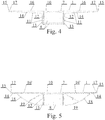
Fig. 1 presents the blind-slat photovoltaic module in the vertical cross-section;Fig. 2 - a simplified blind-slat photovoltaic module joined with its lock and holder in the vertical cross-section;Fig. 3 - the same module in the side view;Fig. 4 - the blind-slat photovoltaic module with the two-piece holder of its lock, in the vertical cross-section;Fig. 5 - the same module in an embodiment with a variation of the two-piece lock with its holder, in the vertical cross-section. - As shown in
Figure 1 , the blind-slat photovoltaic module constitutes a laminate 1 having a layered structure composed of twoouter layers lamination films photovoltaic cells 6 disposed between said films and permanently joined with them. - The laminate 1 has layered structure analogous to this described in Example 1, and the only difference in its structure consists in that its
outer layer 2 is made of glass pane with thickness 0.5 mm, and the secondouter layer 3 is made of glass pane with thickness 1.8 mm. - Laminate 1 (not shown in figures) lacks the layer of
photovoltaic cells 6 and comprises only twoouter layers - The laminate 1, not shown in the figures, comprises only one layer being a glass pane with thickness 1.5 mm.
- In all example embodiments 1-4 of laminate 1, the used glass was strengthened by means of chemical method consisting in immersing glass panes in salt bath and larding their surfaces with larger ions under pressure.
- As shown in
Figs. 2 and 3 , the blind-slat photovoltaic module has laminate 1 withoutphotovoltaic cells 6 which is joined permanently with twooffsets 7 oflock 8 having the form of tube with rectangular cross-section by means of silicone 9. - The blind-slat photovoltaic module shown in
Fig. 4 has laminate 1 joined permanently with twooffsets 7 oflock 8, by means of double-sided highly-adhesive tape 10, whereaslock 8 is fixed in a two-piece metal holder 11 and attached by means ofscrews 12 to itsvertical angle arms 13, both horizontally oriented trapezoidal supportingarms 14 of which are provided withvertical offsets 15 at their ends, whereas laminate 1 is disposed between said offsets and joined additionally with upper surfaces of said arms by means of layers ofstructural silicone 16, whereas between both ends of the laminate 1 andvertical offsets 15 disposed arerubber spacing elements 17 preventing said laminate from moving and protecting its glass edges against contact with metal elements of horizontaltrapezoidal arms 14 of themetal holder 11 which could damage the glass of laminate 1 as a result of thermal expansion occurring in both the laminate and the metal elements. - The blind-slat photovoltaic module shown in
Fig. 5 has structure identical to this of the module slat shown inFig. 4 , except for the shape of the two-piece metal holder 11, with lower ends ofvertical arms 13 of the holder are joined with its supportingarms 14 by means ofelements 18 with profiles representing circular segments with innerstiffening ribs 19 and the means joining additionally the laminate 1 with upper surfaces ofhorizontal arms 14 of the holder, said means in this embodiment being a photo-setting adhesive 16'. - The blind slat for photovoltaic module shown in
Fig. 4 has laminate 1 joined permanently with twooffsets 7 oflock 8, by means of double-sided highly-adhesive tape 10, whereaslock 8 is fixed in a two-piece metal holder 11 and attached by means ofscrews 12 to itsvertical angle arms 13, both horizontally oriented trapezoidal supportingarms 14 of which are provided withvertical offsets 15 at their ends, whereas laminate 1 is disposed between said offsets and joined additionally with upper surfaces of said arms by means of layers ofstructural silicone 16, whereas between both ends of the laminate 1 andvertical offsets 15 disposed arerubber spacing elements 17 preventing said laminate from moving and protecting its glass edges against contact with metal elements of horizontaltrapezoidal arms 14 of themetal holder 11 which could damage the glass of laminate 1 as a result of thermal expansion occurring in both the laminate and the metal elements. - The blind slat for photovoltaic module shown in
Fig. 5 has structure identical to this of the photovoltaic blind slat shown inFig. 4 , except for the shape of the two-piece metal holder 11, with lower ends ofvertical arms 13 of the holder are joined with its supportingarms 14 by means ofelements 18 with profiles representing circular segments with innerstiffening ribs 19 and the means joining additionally the laminate 1 with upper surfaces ofhorizontal arms 14 of the holder, said means in this embodiment being a photo-setting adhesive 16'.
Claims (5)
- (new) A blind-slat photovoltaic module for a sunshade with blinds, said module comprising a glass laminate (1) in the form of flat panes with laminar structure comprising a layer of photovoltaic cells (6) disposed between two outer layers which are glass panes (2, 3) with thickness from 0.5 mm to 1.8 mm strengthened chemically in salt bath, laminated together by means of two layers of lamination films (4, 5), wherein in the glass laminate (1) the layer of photovoltaic cells is disposed between the layers of lamination films (4, 5), and where the layer of photovoltaic cells has an absorber, preferably perovskyte.
- The blind-slat photovoltaic module according to claim 1 characterised in that the absorber for the photovoltaic cell disposed in the laminate (1) are quantum dots (QDSC).
- The blind-slat photovoltaic module according to claim 1 characterised in that the absorber for the photovoltaic cell disposed in the laminate is a dye-sensitised solar cell (DSSC).
- (new) The blind-slat photovoltaic module according to claim 1 characterised in that its glass laminate (1) rests on two offsets (7) of a lock (7) having, in its transverse cross-section, the shape of a rectangular tube and fixed in a two-piece metal holder (11) provided with vertical offsets (15), whereas between said offsets and both ends of the laminate (1) rubber spacing elements (17) are disposed, and wherein the laminate of the blind slat is joined inseparably with the offsets (7) of the lock (8) by means of double-sided highly adhesive tape (10).
- (new) The blind-slat photovoltaic module according to claim 4 characterised in that the glass laminate (1) is joined inseparably with horizontal supporting arms (14) of the two-piece metal holder (11) by means of a layer of a photo-setting adhesive (16') or a layer of structural silicone (16) or a layer of a double-sided adhesive tape (10).
Priority Applications (3)
| Application Number | Priority Date | Filing Date | Title |
|---|---|---|---|
| PL15460115T PL3182467T3 (en) | 2015-12-15 | 2015-12-15 | A blind slat for a photovoltaic module and a method of joining it with the module |
| EP15460115.7A EP3182467B1 (en) | 2015-12-15 | 2015-12-15 | A blind slat for a photovoltaic module and a method of joining it with the module |
| SI201531137T SI3182467T1 (en) | 2015-12-15 | 2015-12-15 | A blind slat for a photovoltaic module and a method of joining it with the module |
Applications Claiming Priority (1)
| Application Number | Priority Date | Filing Date | Title |
|---|---|---|---|
| EP15460115.7A EP3182467B1 (en) | 2015-12-15 | 2015-12-15 | A blind slat for a photovoltaic module and a method of joining it with the module |
Publications (2)
| Publication Number | Publication Date |
|---|---|
| EP3182467A1 EP3182467A1 (en) | 2017-06-21 |
| EP3182467B1 true EP3182467B1 (en) | 2019-12-25 |
Family
ID=55072509
Family Applications (1)
| Application Number | Title | Priority Date | Filing Date |
|---|---|---|---|
| EP15460115.7A Active EP3182467B1 (en) | 2015-12-15 | 2015-12-15 | A blind slat for a photovoltaic module and a method of joining it with the module |
Country Status (3)
| Country | Link |
|---|---|
| EP (1) | EP3182467B1 (en) |
| PL (1) | PL3182467T3 (en) |
| SI (1) | SI3182467T1 (en) |
Citations (1)
| Publication number | Priority date | Publication date | Assignee | Title |
|---|---|---|---|---|
| US20150155410A1 (en) * | 2013-12-04 | 2015-06-04 | Changzhou Almaden Co., Ltd. | High efficiency double-glass solar modules |
Family Cites Families (11)
| Publication number | Priority date | Publication date | Assignee | Title |
|---|---|---|---|---|
| US5221363A (en) * | 1991-02-28 | 1993-06-22 | Lockheed Missiles & Space Company, Inc. | Solar cell window fitting |
| DE4139980A1 (en) * | 1991-12-04 | 1993-06-09 | Mwb Messwandler-Bau Ag, 8600 Bamberg, De | DEVICE FOR COVERING DOORS, WINDOWS OR THE LIKE ROOM LOCKING DEVICES |
| WO2002101839A1 (en) | 2001-06-11 | 2002-12-19 | Powertile Limited | Photovoltaic tiles |
| PL207060B1 (en) | 2002-12-30 | 2010-10-29 | Inst Farmaceutyczny | New application of 22R-(11, 16)-16,17-[butylidene-bis-oxy)]-11,21-dihydroxypregna-1,4-diene-3,20-dione |
| CN201084738Y (en) | 2007-09-29 | 2008-07-09 | 上海耀华皮尔金顿玻璃股份有限公司 | A solar photovoltaic electricity-generation laminated glass |
| CN201285767Y (en) | 2008-10-13 | 2009-08-05 | 杨锦怀 | Photoelectric module |
| US20110146753A1 (en) * | 2009-12-17 | 2011-06-23 | Victor F. Johnson | Solar energy generation system |
| DE102011009879A1 (en) * | 2011-01-31 | 2012-08-02 | Lohmann Gmbh & Co Kg | System for vapor-tight bonding of glass panes, where the vapor-tight bond is produced by an adhesive tape or by post-processing with liquid adhesives or sealants and the adhesive tape is a strapless transfer adhesive tape |
| WO2013062576A2 (en) * | 2011-10-28 | 2013-05-02 | Solarpath, Inc. | Solar window and solar wall structure and method |
| ES2438441B1 (en) | 2012-06-14 | 2014-10-22 | Onyx Solar Energy, S.L. | TRANSITABLE PHOTOVOLTAIC SOIL. |
| PL230401B1 (en) | 2013-10-14 | 2018-10-31 | Ml System Spólka Akcyjna | System of sun shades with shutters |
-
2015
- 2015-12-15 EP EP15460115.7A patent/EP3182467B1/en active Active
- 2015-12-15 PL PL15460115T patent/PL3182467T3/en unknown
- 2015-12-15 SI SI201531137T patent/SI3182467T1/en unknown
Patent Citations (1)
| Publication number | Priority date | Publication date | Assignee | Title |
|---|---|---|---|---|
| US20150155410A1 (en) * | 2013-12-04 | 2015-06-04 | Changzhou Almaden Co., Ltd. | High efficiency double-glass solar modules |
Also Published As
| Publication number | Publication date |
|---|---|
| EP3182467A1 (en) | 2017-06-21 |
| PL3182467T3 (en) | 2020-06-15 |
| SI3182467T1 (en) | 2020-04-30 |
Similar Documents
| Publication | Publication Date | Title |
|---|---|---|
| AU2022279533A1 (en) | Window-integrated transparent photovoltaic module | |
| KR101180234B1 (en) | Building integrated photovoltaic module with design layer | |
| EP3794207B1 (en) | Electric potentially-driven shade including shutter supporting surface-modified conductive coating, methods of making the same and method of operating the same | |
| CN102439493B (en) | Integration of optical element in insulated glazing unit | |
| EP1564816A1 (en) | Curved photovoltaic module and its production method | |
| US11959334B2 (en) | Multifunctional glazing unit | |
| DE102009022125A1 (en) | Insulating glass composite with obliquely arranged photovoltaic cells and methods of manufacture and application | |
| EP3794206B1 (en) | Electric potentially-driven shade with improved coil strength, methods of making the same and method of operating the same | |
| US20130061542A1 (en) | Photovoltaic window assembly with solar control properties | |
| CN101661963A (en) | Heat insulation type film solar battery structure | |
| EP3818237B1 (en) | Electric potentially-driven shade with improved coil strength, method of making the same and method of operating the same | |
| WO2011101682A2 (en) | Concentrating evacuated photovoltaic glazing panel | |
| KR200420311Y1 (en) | Insulated Glass PV | |
| EP3203533B1 (en) | A laminated thermally insulating photovoltaic module | |
| CN104221109A (en) | Hybrid solar cells integrated glassblock and prestressed panel made of dry-assembled glassblocks for construction of traslucent building envelopes | |
| EP3182467B1 (en) | A blind slat for a photovoltaic module and a method of joining it with the module | |
| CN201527981U (en) | Heat-insulation thin-film solar cell structure | |
| KR20070074439A (en) | Integral multilayer glass PV for building exterior | |
| JP2014175402A (en) | Solar cell module | |
| CN101922210A (en) | Multifunctional photovoltaic component and manufacturing method thereof | |
| JP3745873B2 (en) | Double-layer glass with louver | |
| WO2018091576A1 (en) | Multichamber gas-filled insulated glass unit | |
| CN210343116U (en) | A glass luffer board structure for building window | |
| JP5968393B2 (en) | Integration of optical elements in an insulating glass unit | |
| WO2022140867A1 (en) | Construction system for a double-glazed window with an interior space filled with a phase-change material that improves energy efficiency |
Legal Events
| Date | Code | Title | Description |
|---|---|---|---|
| PUAI | Public reference made under article 153(3) epc to a published international application that has entered the european phase |
Free format text: ORIGINAL CODE: 0009012 |
|
| STAA | Information on the status of an ep patent application or granted ep patent |
Free format text: STATUS: THE APPLICATION HAS BEEN PUBLISHED |
|
| AK | Designated contracting states |
Kind code of ref document: A1 Designated state(s): AL AT BE BG CH CY CZ DE DK EE ES FI FR GB GR HR HU IE IS IT LI LT LU LV MC MK MT NL NO PL PT RO RS SE SI SK SM TR |
|
| AX | Request for extension of the european patent |
Extension state: BA ME |
|
| STAA | Information on the status of an ep patent application or granted ep patent |
Free format text: STATUS: REQUEST FOR EXAMINATION WAS MADE |
|
| 17P | Request for examination filed |
Effective date: 20171129 |
|
| RBV | Designated contracting states (corrected) |
Designated state(s): AL AT BE BG CH CY CZ DE DK EE ES FI FR GB GR HR HU IE IS IT LI LT LU LV MC MK MT NL NO PL PT RO RS SE SI SK SM TR |
|
| STAA | Information on the status of an ep patent application or granted ep patent |
Free format text: STATUS: EXAMINATION IS IN PROGRESS |
|
| 17Q | First examination report despatched |
Effective date: 20180724 |
|
| GRAP | Despatch of communication of intention to grant a patent |
Free format text: ORIGINAL CODE: EPIDOSNIGR1 |
|
| STAA | Information on the status of an ep patent application or granted ep patent |
Free format text: STATUS: GRANT OF PATENT IS INTENDED |
|
| GRAS | Grant fee paid |
Free format text: ORIGINAL CODE: EPIDOSNIGR3 |
|
| INTG | Intention to grant announced |
Effective date: 20190911 |
|
| GRAA | (expected) grant |
Free format text: ORIGINAL CODE: 0009210 |
|
| STAA | Information on the status of an ep patent application or granted ep patent |
Free format text: STATUS: THE PATENT HAS BEEN GRANTED |
|
| RIN1 | Information on inventor provided before grant (corrected) |
Inventor name: STANEK, OLGA Inventor name: CYCON, DAWID Inventor name: CHOCHOROWSKI, WIKTOR Inventor name: STANEK, EDYTA |
|
| AK | Designated contracting states |
Kind code of ref document: B1 Designated state(s): AL AT BE BG CH CY CZ DE DK EE ES FI FR GB GR HR HU IE IS IT LI LT LU LV MC MK MT NL NO PL PT RO RS SE SI SK SM TR |
|
| REG | Reference to a national code |
Ref country code: GB Ref legal event code: FG4D |
|
| REG | Reference to a national code |
Ref country code: CH Ref legal event code: EP |
|
| REG | Reference to a national code |
Ref country code: AT Ref legal event code: REF Ref document number: 1218078 Country of ref document: AT Kind code of ref document: T Effective date: 20200115 |
|
| REG | Reference to a national code |
Ref country code: DE Ref legal event code: R096 Ref document number: 602015044198 Country of ref document: DE |
|
| REG | Reference to a national code |
Ref country code: IE Ref legal event code: FG4D |
|
| REG | Reference to a national code |
Ref country code: CH Ref legal event code: NV Representative=s name: KAMINSKI HARMANN PATENTANWAELTE AG, LI |
|
| REG | Reference to a national code |
Ref country code: NL Ref legal event code: MP Effective date: 20191225 |
|
| PG25 | Lapsed in a contracting state [announced via postgrant information from national office to epo] |
Ref country code: LT Free format text: LAPSE BECAUSE OF FAILURE TO SUBMIT A TRANSLATION OF THE DESCRIPTION OR TO PAY THE FEE WITHIN THE PRESCRIBED TIME-LIMIT Effective date: 20191225 Ref country code: GR Free format text: LAPSE BECAUSE OF FAILURE TO SUBMIT A TRANSLATION OF THE DESCRIPTION OR TO PAY THE FEE WITHIN THE PRESCRIBED TIME-LIMIT Effective date: 20200326 Ref country code: BG Free format text: LAPSE BECAUSE OF FAILURE TO SUBMIT A TRANSLATION OF THE DESCRIPTION OR TO PAY THE FEE WITHIN THE PRESCRIBED TIME-LIMIT Effective date: 20200325 Ref country code: FI Free format text: LAPSE BECAUSE OF FAILURE TO SUBMIT A TRANSLATION OF THE DESCRIPTION OR TO PAY THE FEE WITHIN THE PRESCRIBED TIME-LIMIT Effective date: 20191225 Ref country code: LV Free format text: LAPSE BECAUSE OF FAILURE TO SUBMIT A TRANSLATION OF THE DESCRIPTION OR TO PAY THE FEE WITHIN THE PRESCRIBED TIME-LIMIT Effective date: 20191225 Ref country code: SE Free format text: LAPSE BECAUSE OF FAILURE TO SUBMIT A TRANSLATION OF THE DESCRIPTION OR TO PAY THE FEE WITHIN THE PRESCRIBED TIME-LIMIT Effective date: 20191225 |
|
| REG | Reference to a national code |
Ref country code: NO Ref legal event code: T2 Effective date: 20191225 Ref country code: LT Ref legal event code: MG4D |
|
| PG25 | Lapsed in a contracting state [announced via postgrant information from national office to epo] |
Ref country code: RS Free format text: LAPSE BECAUSE OF FAILURE TO SUBMIT A TRANSLATION OF THE DESCRIPTION OR TO PAY THE FEE WITHIN THE PRESCRIBED TIME-LIMIT Effective date: 20191225 Ref country code: HR Free format text: LAPSE BECAUSE OF FAILURE TO SUBMIT A TRANSLATION OF THE DESCRIPTION OR TO PAY THE FEE WITHIN THE PRESCRIBED TIME-LIMIT Effective date: 20191225 |
|
| PG25 | Lapsed in a contracting state [announced via postgrant information from national office to epo] |
Ref country code: AL Free format text: LAPSE BECAUSE OF FAILURE TO SUBMIT A TRANSLATION OF THE DESCRIPTION OR TO PAY THE FEE WITHIN THE PRESCRIBED TIME-LIMIT Effective date: 20191225 |
|
| PG25 | Lapsed in a contracting state [announced via postgrant information from national office to epo] |
Ref country code: NL Free format text: LAPSE BECAUSE OF FAILURE TO SUBMIT A TRANSLATION OF THE DESCRIPTION OR TO PAY THE FEE WITHIN THE PRESCRIBED TIME-LIMIT Effective date: 20191225 Ref country code: EE Free format text: LAPSE BECAUSE OF FAILURE TO SUBMIT A TRANSLATION OF THE DESCRIPTION OR TO PAY THE FEE WITHIN THE PRESCRIBED TIME-LIMIT Effective date: 20191225 Ref country code: RO Free format text: LAPSE BECAUSE OF FAILURE TO SUBMIT A TRANSLATION OF THE DESCRIPTION OR TO PAY THE FEE WITHIN THE PRESCRIBED TIME-LIMIT Effective date: 20191225 Ref country code: PT Free format text: LAPSE BECAUSE OF FAILURE TO SUBMIT A TRANSLATION OF THE DESCRIPTION OR TO PAY THE FEE WITHIN THE PRESCRIBED TIME-LIMIT Effective date: 20200520 Ref country code: CZ Free format text: LAPSE BECAUSE OF FAILURE TO SUBMIT A TRANSLATION OF THE DESCRIPTION OR TO PAY THE FEE WITHIN THE PRESCRIBED TIME-LIMIT Effective date: 20191225 |
|
| PG25 | Lapsed in a contracting state [announced via postgrant information from national office to epo] |
Ref country code: SK Free format text: LAPSE BECAUSE OF FAILURE TO SUBMIT A TRANSLATION OF THE DESCRIPTION OR TO PAY THE FEE WITHIN THE PRESCRIBED TIME-LIMIT Effective date: 20191225 Ref country code: SM Free format text: LAPSE BECAUSE OF FAILURE TO SUBMIT A TRANSLATION OF THE DESCRIPTION OR TO PAY THE FEE WITHIN THE PRESCRIBED TIME-LIMIT Effective date: 20191225 Ref country code: IS Free format text: LAPSE BECAUSE OF FAILURE TO SUBMIT A TRANSLATION OF THE DESCRIPTION OR TO PAY THE FEE WITHIN THE PRESCRIBED TIME-LIMIT Effective date: 20200425 |
|
| REG | Reference to a national code |
Ref country code: DE Ref legal event code: R097 Ref document number: 602015044198 Country of ref document: DE |
|
| REG | Reference to a national code |
Ref country code: AT Ref legal event code: UEP Ref document number: 1218078 Country of ref document: AT Kind code of ref document: T Effective date: 20191225 |
|
| PG25 | Lapsed in a contracting state [announced via postgrant information from national office to epo] |
Ref country code: DK Free format text: LAPSE BECAUSE OF FAILURE TO SUBMIT A TRANSLATION OF THE DESCRIPTION OR TO PAY THE FEE WITHIN THE PRESCRIBED TIME-LIMIT Effective date: 20191225 Ref country code: ES Free format text: LAPSE BECAUSE OF FAILURE TO SUBMIT A TRANSLATION OF THE DESCRIPTION OR TO PAY THE FEE WITHIN THE PRESCRIBED TIME-LIMIT Effective date: 20191225 |
|
| PLBE | No opposition filed within time limit |
Free format text: ORIGINAL CODE: 0009261 |
|
| STAA | Information on the status of an ep patent application or granted ep patent |
Free format text: STATUS: NO OPPOSITION FILED WITHIN TIME LIMIT |
|
| 26N | No opposition filed |
Effective date: 20200928 |
|
| PG25 | Lapsed in a contracting state [announced via postgrant information from national office to epo] |
Ref country code: IT Free format text: LAPSE BECAUSE OF FAILURE TO SUBMIT A TRANSLATION OF THE DESCRIPTION OR TO PAY THE FEE WITHIN THE PRESCRIBED TIME-LIMIT Effective date: 20191225 |
|
| PGFP | Annual fee paid to national office [announced via postgrant information from national office to epo] |
Ref country code: SI Payment date: 20201026 Year of fee payment: 6 |
|
| GBPC | Gb: european patent ceased through non-payment of renewal fee |
Effective date: 20201215 |
|
| PG25 | Lapsed in a contracting state [announced via postgrant information from national office to epo] |
Ref country code: MC Free format text: LAPSE BECAUSE OF FAILURE TO SUBMIT A TRANSLATION OF THE DESCRIPTION OR TO PAY THE FEE WITHIN THE PRESCRIBED TIME-LIMIT Effective date: 20191225 |
|
| REG | Reference to a national code |
Ref country code: BE Ref legal event code: MM Effective date: 20201231 |
|
| PG25 | Lapsed in a contracting state [announced via postgrant information from national office to epo] |
Ref country code: IE Free format text: LAPSE BECAUSE OF NON-PAYMENT OF DUE FEES Effective date: 20201215 Ref country code: FR Free format text: LAPSE BECAUSE OF NON-PAYMENT OF DUE FEES Effective date: 20201231 Ref country code: LU Free format text: LAPSE BECAUSE OF NON-PAYMENT OF DUE FEES Effective date: 20201215 |
|
| PG25 | Lapsed in a contracting state [announced via postgrant information from national office to epo] |
Ref country code: GB Free format text: LAPSE BECAUSE OF NON-PAYMENT OF DUE FEES Effective date: 20201215 |
|
| PGFP | Annual fee paid to national office [announced via postgrant information from national office to epo] |
Ref country code: DE Payment date: 20211210 Year of fee payment: 7 Ref country code: NO Payment date: 20211115 Year of fee payment: 7 Ref country code: AT Payment date: 20211202 Year of fee payment: 7 |
|
| PGFP | Annual fee paid to national office [announced via postgrant information from national office to epo] |
Ref country code: CH Payment date: 20211109 Year of fee payment: 7 |
|
| PG25 | Lapsed in a contracting state [announced via postgrant information from national office to epo] |
Ref country code: TR Free format text: LAPSE BECAUSE OF FAILURE TO SUBMIT A TRANSLATION OF THE DESCRIPTION OR TO PAY THE FEE WITHIN THE PRESCRIBED TIME-LIMIT Effective date: 20191225 Ref country code: MT Free format text: LAPSE BECAUSE OF FAILURE TO SUBMIT A TRANSLATION OF THE DESCRIPTION OR TO PAY THE FEE WITHIN THE PRESCRIBED TIME-LIMIT Effective date: 20191225 Ref country code: CY Free format text: LAPSE BECAUSE OF FAILURE TO SUBMIT A TRANSLATION OF THE DESCRIPTION OR TO PAY THE FEE WITHIN THE PRESCRIBED TIME-LIMIT Effective date: 20191225 |
|
| PG25 | Lapsed in a contracting state [announced via postgrant information from national office to epo] |
Ref country code: MK Free format text: LAPSE BECAUSE OF FAILURE TO SUBMIT A TRANSLATION OF THE DESCRIPTION OR TO PAY THE FEE WITHIN THE PRESCRIBED TIME-LIMIT Effective date: 20191225 |
|
| PG25 | Lapsed in a contracting state [announced via postgrant information from national office to epo] |
Ref country code: BE Free format text: LAPSE BECAUSE OF NON-PAYMENT OF DUE FEES Effective date: 20201231 |
|
| REG | Reference to a national code |
Ref country code: SI Ref legal event code: KO00 Effective date: 20220816 |
|
| PG25 | Lapsed in a contracting state [announced via postgrant information from national office to epo] |
Ref country code: SI Free format text: LAPSE BECAUSE OF NON-PAYMENT OF DUE FEES Effective date: 20211216 |
|
| PGFP | Annual fee paid to national office [announced via postgrant information from national office to epo] |
Ref country code: PL Payment date: 20221108 Year of fee payment: 8 |
|
| REG | Reference to a national code |
Ref country code: DE Ref legal event code: R119 Ref document number: 602015044198 Country of ref document: DE |
|
| REG | Reference to a national code |
Ref country code: NO Ref legal event code: MMEP |
|
| REG | Reference to a national code |
Ref country code: CH Ref legal event code: PL |
|
| REG | Reference to a national code |
Ref country code: AT Ref legal event code: MM01 Ref document number: 1218078 Country of ref document: AT Kind code of ref document: T Effective date: 20221215 |
|
| PG25 | Lapsed in a contracting state [announced via postgrant information from national office to epo] |
Ref country code: NO Free format text: LAPSE BECAUSE OF NON-PAYMENT OF DUE FEES Effective date: 20221231 Ref country code: LI Free format text: LAPSE BECAUSE OF NON-PAYMENT OF DUE FEES Effective date: 20221231 Ref country code: DE Free format text: LAPSE BECAUSE OF NON-PAYMENT OF DUE FEES Effective date: 20230701 Ref country code: CH Free format text: LAPSE BECAUSE OF NON-PAYMENT OF DUE FEES Effective date: 20221231 Ref country code: AT Free format text: LAPSE BECAUSE OF NON-PAYMENT OF DUE FEES Effective date: 20221215 |
|
| PGFP | Annual fee paid to national office [announced via postgrant information from national office to epo] |
Ref country code: PL Payment date: 20231121 Year of fee payment: 9 |