EP3182330B1 - Method and system for remotely annotating an object in real-time - Google Patents
Method and system for remotely annotating an object in real-time Download PDFInfo
- Publication number
- EP3182330B1 EP3182330B1 EP16154619.7A EP16154619A EP3182330B1 EP 3182330 B1 EP3182330 B1 EP 3182330B1 EP 16154619 A EP16154619 A EP 16154619A EP 3182330 B1 EP3182330 B1 EP 3182330B1
- Authority
- EP
- European Patent Office
- Prior art keywords
- real
- data
- video stream
- time
- frame
- Prior art date
- Legal status (The legal status is an assumption and is not a legal conclusion. Google has not performed a legal analysis and makes no representation as to the accuracy of the status listed.)
- Active
Links
- 238000000034 method Methods 0.000 title claims description 36
- 238000004891 communication Methods 0.000 claims description 20
- 238000009877 rendering Methods 0.000 claims description 6
- 230000000007 visual effect Effects 0.000 claims description 5
- 230000000977 initiatory effect Effects 0.000 claims 1
- 230000003190 augmentative effect Effects 0.000 description 11
- 230000005540 biological transmission Effects 0.000 description 11
- 238000003860 storage Methods 0.000 description 10
- 238000012545 processing Methods 0.000 description 9
- 238000010586 diagram Methods 0.000 description 7
- 230000006870 function Effects 0.000 description 4
- 238000004519 manufacturing process Methods 0.000 description 3
- 230000003287 optical effect Effects 0.000 description 3
- 238000012546 transfer Methods 0.000 description 3
- 238000013459 approach Methods 0.000 description 2
- 238000009826 distribution Methods 0.000 description 2
- 238000005516 engineering process Methods 0.000 description 2
- 239000003550 marker Substances 0.000 description 2
- 238000012986 modification Methods 0.000 description 2
- 230000004048 modification Effects 0.000 description 2
- 230000008569 process Effects 0.000 description 2
- 230000001360 synchronised effect Effects 0.000 description 2
- VYZAMTAEIAYCRO-UHFFFAOYSA-N Chromium Chemical compound [Cr] VYZAMTAEIAYCRO-UHFFFAOYSA-N 0.000 description 1
- RYGMFSIKBFXOCR-UHFFFAOYSA-N Copper Chemical compound [Cu] RYGMFSIKBFXOCR-UHFFFAOYSA-N 0.000 description 1
- 101100521334 Mus musculus Prom1 gene Proteins 0.000 description 1
- 241000489455 Sitta europaea Species 0.000 description 1
- 230000001413 cellular effect Effects 0.000 description 1
- 238000006243 chemical reaction Methods 0.000 description 1
- 239000002131 composite material Substances 0.000 description 1
- 238000013461 design Methods 0.000 description 1
- 238000011156 evaluation Methods 0.000 description 1
- 239000000835 fiber Substances 0.000 description 1
- 238000007667 floating Methods 0.000 description 1
- 230000003993 interaction Effects 0.000 description 1
- 239000004973 liquid crystal related substance Substances 0.000 description 1
- 230000007774 longterm Effects 0.000 description 1
- 238000012423 maintenance Methods 0.000 description 1
- 238000010295 mobile communication Methods 0.000 description 1
- 239000013307 optical fiber Substances 0.000 description 1
- 238000013515 script Methods 0.000 description 1
- 230000001052 transient effect Effects 0.000 description 1
- 230000007704 transition Effects 0.000 description 1
Images


Classifications
-
- G—PHYSICS
- G06—COMPUTING; CALCULATING OR COUNTING
- G06Q—INFORMATION AND COMMUNICATION TECHNOLOGY [ICT] SPECIALLY ADAPTED FOR ADMINISTRATIVE, COMMERCIAL, FINANCIAL, MANAGERIAL OR SUPERVISORY PURPOSES; SYSTEMS OR METHODS SPECIALLY ADAPTED FOR ADMINISTRATIVE, COMMERCIAL, FINANCIAL, MANAGERIAL OR SUPERVISORY PURPOSES, NOT OTHERWISE PROVIDED FOR
- G06Q10/00—Administration; Management
- G06Q10/10—Office automation; Time management
- G06Q10/101—Collaborative creation, e.g. joint development of products or services
-
- G—PHYSICS
- G06—COMPUTING; CALCULATING OR COUNTING
- G06T—IMAGE DATA PROCESSING OR GENERATION, IN GENERAL
- G06T11/00—2D [Two Dimensional] image generation
- G06T11/60—Editing figures and text; Combining figures or text
-
- G—PHYSICS
- G06—COMPUTING; CALCULATING OR COUNTING
- G06T—IMAGE DATA PROCESSING OR GENERATION, IN GENERAL
- G06T19/00—Manipulating 3D models or images for computer graphics
- G06T19/20—Editing of 3D images, e.g. changing shapes or colours, aligning objects or positioning parts
-
- G—PHYSICS
- G06—COMPUTING; CALCULATING OR COUNTING
- G06V—IMAGE OR VIDEO RECOGNITION OR UNDERSTANDING
- G06V20/00—Scenes; Scene-specific elements
- G06V20/20—Scenes; Scene-specific elements in augmented reality scenes
-
- G—PHYSICS
- G09—EDUCATION; CRYPTOGRAPHY; DISPLAY; ADVERTISING; SEALS
- G09B—EDUCATIONAL OR DEMONSTRATION APPLIANCES; APPLIANCES FOR TEACHING, OR COMMUNICATING WITH, THE BLIND, DEAF OR MUTE; MODELS; PLANETARIA; GLOBES; MAPS; DIAGRAMS
- G09B5/00—Electrically-operated educational appliances
- G09B5/08—Electrically-operated educational appliances providing for individual presentation of information to a plurality of student stations
- G09B5/14—Electrically-operated educational appliances providing for individual presentation of information to a plurality of student stations with provision for individual teacher-student communication
-
- G—PHYSICS
- G06—COMPUTING; CALCULATING OR COUNTING
- G06V—IMAGE OR VIDEO RECOGNITION OR UNDERSTANDING
- G06V10/00—Arrangements for image or video recognition or understanding
- G06V10/40—Extraction of image or video features
- G06V10/46—Descriptors for shape, contour or point-related descriptors, e.g. scale invariant feature transform [SIFT] or bags of words [BoW]; Salient regional features
- G06V10/462—Salient features, e.g. scale invariant feature transforms [SIFT]
-
- H—ELECTRICITY
- H04—ELECTRIC COMMUNICATION TECHNIQUE
- H04M—TELEPHONIC COMMUNICATION
- H04M2203/00—Aspects of automatic or semi-automatic exchanges
- H04M2203/35—Aspects of automatic or semi-automatic exchanges related to information services provided via a voice call
- H04M2203/359—Augmented reality
-
- H—ELECTRICITY
- H04—ELECTRIC COMMUNICATION TECHNIQUE
- H04M—TELEPHONIC COMMUNICATION
- H04M3/00—Automatic or semi-automatic exchanges
- H04M3/42—Systems providing special services or facilities to subscribers
- H04M3/56—Arrangements for connecting several subscribers to a common circuit, i.e. affording conference facilities
- H04M3/567—Multimedia conference systems
-
- H—ELECTRICITY
- H04—ELECTRIC COMMUNICATION TECHNIQUE
- H04N—PICTORIAL COMMUNICATION, e.g. TELEVISION
- H04N7/00—Television systems
- H04N7/14—Systems for two-way working
- H04N7/15—Conference systems
Definitions
- the present subject matter generally relates to annotating an object. More particularly, but not exclusively, the present disclosure discloses a system and a method for remotely annotating at least one object in real-time.
- Conventional systems relate to retrieving physical parameters of an object and further visualising the object for augmenting the object.
- sensor is coupled to the object to generate live data and the physical parameters computed based on the live data.
- the physical parameters are used for visualising the object.
- method for augmenting is disclosed where image of the object is received which includes information defining a sampled frame of a video being captured by an electronic device in substantially real time. Further, content of the object is obtained based on the information and is used for display of the object on the electronic device.
- the display of the object is configured to enable a user to interact with the object through the display.
- an approach for real-time manipulation of objects within multiple dynamic and augmented video streams synchronized in an Augmented Reality (AR) or multi-dimensional space is disclosed.
- users of first AR system will be able to connect with participants of a second AR system and to share their initial and/or augmented video streams with the participants to enhance the AR experience from one participant to many.
- real time synchronization of augmented video streams in the AR systems the user and the participants will be able to see, share, manipulate and interact with the augmented objects either in his/her own augmented video streams or in the augmented video streams of another user.
- an augmented reality technology incorporated in land surveying, 3D laser scanning, and digital modelling processes is disclosed.
- mobile device is configured to display an augmented reality image comprising a real view of a physical structure in real environment and a 3D digital model of an unbuilt design element overlaid on top of the physical structure at its intended tie-in location.
- KLEIBER et al Evaluation of a Mobile AR Tele-Maintenance System, In: Universal Access in Human-Computer Interaction, Applications and Services, edited by C. Stephanidis C., Lecture Notes in Computer Science, 2011, Vol. 6768, Springer-Verlag, Berlin, Heidelberg, ISBN 978-3-642-21657-2 discloses a system that provides a synchronous shared visual space for collaborations via a narrowband connection without a direct video link.
- a processor-implemented method for remotely annotating at least one object in real-time a real-time annotating unit for remotely annotating at least one object in real-time, and a non-transitory computer-readable medium as set out in claims 1, 8, and 15 respectively.
- the present disclosure relates to a faster and reliable method for annotating an object in real-time remotely.
- the method includes initially receiving a video stream comprising one or more objects from a site device. At least one object is identified in the video stream which is to be annotated by comparing at least one frame of the video stream with predefined frames comprising the one or more objects in an object database. Further, orientation data of the at least one object is determined and UCID associated with each of the at least one object is obtained from the object database. Further, the UCID is with the at least one object is provided to a remote device. Further, annotated data is received from the remote device which is generated based on the UCID and remote expert inputs, and the received annotation data is converted to three dimensional (3D) space coordinates. The converted annotated data is rendered on the at least one object based on the orientation data for remotely annotating the at least one object.
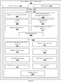
- Figure 1 illustrates an exemplary system for remotely annotating at least one object in real-time in accordance with some embodiments of the present disclosure.
- the exemplary system for annotating at least one object in real-time comprises a real-time annotating unit 101, an object database 105 and a remote device 106.
- the real-time annotating unit 101 comprises I/O interface 102, processor 103 and memory 104.
- the remote device 106 also comprises I/O interface 107, processor 108 and memory 109.
- the real-time annotating unit 101 and the remote device 106 may be implemented in a variety of computing systems, such as a laptop computer, a desktop computer, a Personal Computer (PC), a notebook, a smartphone, a tablet, a server, a network server, and the like.
- the memory 104 in the real-time annotating unit 101 is communicatively coupled to the processor 103.
- the memory 104 stores processor executable instructions which on execution help the real-time annotating unit 101 to annotate at least one object in real-time remotely.
- the processor 102 may comprise at least one data processor for executing program components for annotating the at least one object by receiving the annotated data from the remote device.
- the term "annotated data" is preferably used herein to refer to metadata attached to the object and corresponding to the expert user inputs and aligned with the object's orientation.
- the metadata may include text, in the form of a comment, and/or infographics.
- the real-time annotating unit 101 is configured to receive a video stream via I/O interface 102 comprising one or more objects from a site device.
- the video stream may be captured by a camera embedded with the real-time annotating unit 101.
- at least one object in the video stream which is to be annotated is identified by real-time annotating unit 101.
- An object is identified by comparing at least one frame of the video stream with predefined frames comprising the one or more objects.
- the predefined frames are obtained from the object database via the I/O interface 102.
- orientation data of the at least one object identified in the video stream is determined by the real-time annotating unit 101 and a unique context identifier (UCID) associated with each of the at least one object is obtained.
- UID unique context identifier
- the UCID is obtained from the object database 105.
- the real-time annotating unit 101 further provides the UCID associated with the at least one object to a remote device 106 and receives annotated data from the remote device 106 via the I/O interface 102.
- the annotated data is generated based on the UCID and remote expert inputs at the remote device 106.
- the annotated data is converted to three dimensional (3D) space coordinates and rendered on the at least one object in the video stream based on the orientation data by the real-time annotating unit 101.
- the video stream may be displayed on a display unit associated with the real-time annotating unit 101.
- Communication of the real-time annotating unit 101 is achieved via the communication network through I/O interface 102 of the real-time annotating unit 101.
- the annotated data, the predefined frames and the UCID may be received by the real-time annotating unit 101 in form of data packets.
- the communication network is configured to be in listening mode and accept the data packets.
- the real-time annotating unit 101 decodes the received data packets as one of General Packet Radio Service (GPRS) packets, Open Building Information Exchange (OBiX) files, File Transfer Protocol (FTP) files and others associated with the data packets.
- GPRS General Packet Radio Service
- OBiX Open Building Information Exchange
- FTP File Transfer Protocol
- the memory 109 in the remote device 106 is communicatively coupled to the processor 108.
- the memory 109 stores processor executable instructions which on execution help the remote device 106 to obtain the remote expert inputs and provide the annotated data to the real-time annotation unit 101.
- the processor 108 may comprise at least one data processor for executing program components for receiving UCID from the real-time annotating unit 101.
- predefined object frame associated with the UCID is obtained by the remote device 106 from the object database 105 via I/O interface 107.
- the remote expert inputs are provided on the predefined object frame in the remote device 106.
- the remote expert inputs may be a touch provided through an input module associated with the remote device 106 via I/O interface 107.
- the term "remote expert inputs" is preferably used herein to refer to instructional and/or descriptive data input by an expert on the remote device 106.
- the remote expert inputs may include comments and/or infographics for explanatory purposes.
- the object database can be within the real time annotating unit and remote device each.
- Figure 2 illustrates a detailed block diagram of an exemplary real-time annotating unit with various data and modules for annotating at least one object in real-time from a remote device 106 in accordance with some embodiments of the present disclosure.
- the one or more data 109 and the one or more modules 201 stored in the memory 108 are described herein in detail.
- the one or more data 209 in the memory 104 are processed by the one or more modules 201 of the real-time annotating unit 101.
- the one or more modules 201 may be stored within the memory 104 as shown in Figure 2 .
- the one or more modules 201, communicatively coupled to the processor 103 may also be present outside the memory 104 and implemented as hardware.
- the term module refers to an application specific integrated circuit (ASIC), an electronic circuit, a processor (shared, dedicated, or group) and memory that execute one or more software or firmware programs, a combinational logic circuit, and/or other suitable components that provide the described functionality.
- ASIC application specific integrated circuit
- processor shared, dedicated, or group
- memory that execute one or more software or firmware programs, a combinational logic circuit, and/or other suitable components that provide the described functionality.
- the one or more data 209 may include, for example, at least one frame of video stream 210, predefined frames 211, orientation data 212, UCID 213, annotated data 214, 3D space co-ordinates 215, converted annotated data 216, new UCID 217 and other data 219 for the performance of the real-time annotation unit 101.
- the real-time annotating unit 101 receives the video stream which comprises one or more object from the site device. Further, at least one object from the one or more objects, which is to be annotated, is identified in the video stream. The at least one object is identified by comparing at least one frame of the video stream 210 with predefined frames 211. The at least one frame of the video stream 210 is captured by the real-time annotating unit 101. The predefined frames 211 are obtained from the object database 105. The predefined frames comprises pre-trained frames of the at least one object.
- the orientation data 212 of the at least one object is determined by the real-time annotating unit 101.
- the orientation data 212 is determined by comparing the at least one frame 210 comprising the at least one object with a predefined object frame obtained from an object database.
- the predefined object frame is selected from the predefined frames 211 in the object database 105.
- the UCID 213 associated with each of the at least one object is obtained by the real-time annotating unit 101 from the object database 105.
- the UCID 213 is a unique text associated with each of the at least one object and stored in the object database 105.
- Each of the at least one object is identified from its UCID 213.
- the UCID 213 is provided to the remote device 106.
- the annotated data 214 is received from the remote device 106 which is generated based on the UCID 213 and the remote expert inputs at the remote device 106. Further, the annotated data is converted to 3D space coordinates 215. The 3D space coordinates 215 are determined based on the co-ordinates on the at least one object.
- the converted annotated data 216 is rendered on the at least one object based on the orientation data 212 in the video stream.
- the rendered annotated data may be in a visual format.
- a new object is recognized by the real-time annotating unit 101 and a new UCID 217 is assigned to the new object and provided to the object database 105 for annotations of the new object.
- the other data 218 may refer to such data which can be referred for remotely annotating at least one object by the real-time annotating unit 101.
- the one or more modules 201 may include, for example, object identifying module 202, orientation data determining module 203, UCID module 204, converting module 205, rendering module 206, audio communication module 207 and other modules 208 associated with the real-time annotating unit 101.
- the object identifying module 202 is configured to identify the at least one object in the video stream by comparing the at least one frame of the video stream 210 with the predefined frames 211.
- Orientation data determining module 203 is configured to determine the orientation data 212 of the at least one object identified in the video stream.
- the orientation data 212 is determined by comparing the at least one frame 210 comprising the at least one object with a predefined object frame obtained from an object database.
- the UCID module 204 is used for obtaining the UCID 213 from the object database 105.
- the at least one object is identified and associated UCID 213 is obtained.
- the converting module 205 Upon receiving the annotated data 214 from the remote device 106, the converting module 205 is configured to convert the annotated data 214 to 3D space coordinates and the rendering module 206 is configure to render the converted annotated data 216 on the at least one object in the video stream.
- the other modules 206 may refer to such modules which can be referred for managing the performance of the instrumentation devices 102.
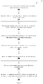
- Figure 3 shows a flowchart illustrating a method for annotating at least one object in real-time from a remote device in accordance with some embodiments of the present disclosure.
- the method comprises one or more blocks for remotely annotating at least one object by a real-time annotating unit 101.
- the method 300 may be described in the general context of computer executable instructions.
- computer executable instructions can include routines, programs, objects, components, data structures, procedures, modules, and functions, which perform particular functions or implement particular abstract data types.
- the method can be implemented in any suitable hardware, software, firmware, or combination thereof.
- the real-time annotating unit 101 receives a video stream comprising one or more objects from a site device.
- the site device may be associated with a camera to capture the video stream.
- At block 302 identify, by the object identifying module 202 in the real-time annotation unit, the at least one object in the video stream which is to be annotated.
- At block 308, render, the rendering module in the real-time annotation unit 101, the annotated data 214 in 3D space coordinates on the at least one object based on the orientation data 212.
- Figure 4 shows a flowchart illustrating a method for identifying at least one object and obtaining UCID of the at least one object in accordance with some embodiments of the present disclosure.
- the method comprises one or more blocks for remotely annotating at least one object by a real-time annotating unit 101.
- the method 400 may be described in the general context of computer executable instructions.
- computer executable instructions can include routines, programs, objects, components, data structures, procedures, modules, and functions, which perform particular functions or implement particular abstract data types.
- the method can be implemented in any suitable hardware, software, firmware, or combination thereof.
- At block 401 capture at least one frame 210 of a video stream from the site device in the real-time annotating unit 101.
- At block 402 convert the at least one frame 210 to gray-scale and reduce frame resolution.
- the at least one frame is converted to gray-scale and frame resolution is reduced for faster processing of the real-time annotating unit 101.
- the key points may be extracted by implementing Oriented Fast and Rotated Brief (ORB) feature detector.
- ORB Oriented Fast and Rotated Brief
- block 404 check if number of key points is greater than a first predefined value. If the number of key points is greater than the first predefined value, perform block 404. If the number of key points is lesser than the first predefined value, perform block 401.
- obtain the UCID of the at least one object form the object database 105 based on the matched key points.
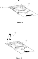
- Figure 5a shows an exemplary embodiment of at least one object 501 in a video stream received from a site device in accordance with some embodiments of the present disclosure.
- the at least one object 501 as shown in Figure 5a may be a Central Processing Unit (CPU) in the video stream, received from the site device and is displayed on a display associated with the real-time annotating unit 101.
- Orientation of the at least one object 501 in the video stream may be different from orientation of the at least one predefined object frame associated with the at least one object 501.
- the at least one frame 210 of the video stream is captured and used to identify the at least one object in the video stream. The identifying of the at least one object is performed by the method as described in Figure 4 .
- Figure 5b shows an exemplary embodiment of at least one object 501 illustrating determination of orientation data of the at least one object 501 in accordance with some embodiments of the present disclosure.
- Figure 5c shows an exemplary embodiment of predefined object frame 502 comprising at least one object for determining orientation data of at least one object in accordance with some embodiments of the present disclosure.
- the orientation data 212 of the at least one object is determined upon the identification.
- the orientation data in determined in xy coordinate space as shown in Figure 5b .
- Orientation data 212 is determined by comparing the at least one frame 210 comprising the at least one object 501 with the predefined object frame.
- the predefined object frame 502 is obtained is selected from the predefined frames in the object database based on the UCID.
- the predefined object frame 502 comprising the at least one object 501 is as shown in the Figure 5c .
- Orientation of the at least one object 501 in the predefined object frame 502 is determined in XY coordinate space.
- the orientation of the at least one object 501 in the video stream and the orientation of the at least one object 501 in the predefined object frame 502 is compared to obtain the orientation data 212.
- Relation between the orientation of the at least one object 501 in the video stream and the orientation of the at least one object 501 in the predefined object frame 502 is given as in equation 1 and 2.
- X ax + by + c gx + hy + 1
- Y dx + ey + f gx + hy + 1 where a, b, c, d, e, f, g and h are constants.
- homogenous coordinates of the at least one object 501 may be given by as in equation 3.
- x y z wx wy wz where w is homogenous vertex coordinates.
- Figure 5d shows an exemplary embodiment of predefined object frame 502 illustrating remote expert inputs provided at remote device in accordance with some embodiments of the present disclosure.
- the UCID 213 associated with the at least one object 501 is obtained from the object database 105 and provided to the remote device 106.
- the remote device 106 fetches the predefined object frame 502 associated with UCID 213 from the object database 105.
- the obtained predefined object frame 502 is displayed on display on the remote device 106.
- the expert at the remote device 106 may provide the remote expert inputs on the display. In one embodiment, the remote expert inputs may be touch of the expert on the display indicating a specific point on the at least one object 501.
- an audio communication is provided between the real-time annotating unit 101 and the remote device 106 for communication between the expert and a user at the real-time annotating unit 101.
- the expert may provide the remote expert inputs through one or more other input modules associated with the remote device 106. Based on the remote expert inputs and the UCID 213, the annotated data 214 is provided to the real-time annotating unit 101.
- Figure 5e shows an exemplary embodiment of at least one object 501 illustrating converting of annotated data 214 in 3D space co-ordinates in accordance with some embodiments of the present disclosure.
- the annotated data 214 is received by the real-time annotation unit 101 in XY coordinate space.
- the XY coordinates of the annotated data 214 is normalized with respect to centre of the orientation of the at least one object 501 initially based on the width and height of the at least one object 501 in the video stream.
- the position of the normalized annotated data on the at least one object 501 is determined based on the orientation data 212 as shown in Figure 5e .
- Figure 5f shows an exemplary embodiment of at least one object 501 illustrating rendering of annotated data in 3D space co-ordinates on at least one object 501 in accordance with some embodiments of the present disclosure
- the normalized annotated data 214 is converted to a 3D model and rendered on the video stream comprising at least one object.
- the 3D model of annotated data may be a marker 503 as shown in Figure 5f .
- the marker 503 points at the at least one object 501 indicating the annotations provided by the expert at the remote device 106.
- Figure 6 is a block diagram of an exemplary computer system for implementing some embodiments consistent with the present disclosure.
- the computer system 600 is used to implement the performance management unit 102.
- the computer system 600 may comprise a central processing unit (“CPU” or "processor") 602.
- the processor 602 may comprise at least one data processor for executing program components for managing the performance of at least one instrumentation device deployed across one or more sites.
- the processor 602 may include specialized processing units such as integrated system (bus) controllers, memory management control units, floating point units, graphics processing units, digital signal processing units, etc.
- the processor 602 may be disposed in communication with one or more input/output (I/O) devices (not shown) via I/O interface 601.
- the I/O interface 601 may employ communication protocols/methods such as, without limitation, audio, analog, digital, monoaural, RCA, stereo, IEEE-1394, serial bus, universal serial bus (USB), infrared, PS/2, BNC, coaxial, component, composite, digital visual interface (DVI), high-definition multimedia interface (HDMI), RF antennas, S-Video, VGA, IEEE 802.n /b/g/n/x, Bluetooth, cellular (e.g., code-division multiple access (CDMA), high-speed packet access (HSPA+), global system for mobile communications (GSM), long-term evolution (LTE), WiMax, or the like), etc.
- CDMA code-division multiple access
- HSPA+ high-speed packet access
- GSM global system for mobile communications
- LTE long-term evolution
- WiMax wireless wide area network
- the computer system 600 may communicate with one or more I/O devices.
- the input device may be an antenna, keyboard, mouse, joystick, (infrared) remote control, camera, card reader, fax machine, dongle, biometric reader, microphone, touch screen, touchpad, trackball, stylus, scanner, storage device, transceiver, video device/source, etc.
- the output device may be a printer, fax machine, video display (e.g., cathode ray tube (CRT), liquid crystal display (LCD), light-emitting diode (LED), plasma, Plasma display panel (PDP), Organic light-emitting diode display (OLED) or the like), audio speaker, etc.
- CTR cathode ray tube
- LCD liquid crystal display
- LED light-emitting diode
- PDP Plasma display panel
- OLED Organic light-emitting diode display
- the computer system 600 is connected to a remote device 612 and an object database 613 through a communication network 611.
- the processor 602 may be disposed in communication with the communication network 609 via a network interface 603.
- the network interface 603 may communicate with the communication network 609.
- the network interface 603 may employ connection protocols including, without limitation, direct connect, Ethernet (e.g., twisted pair 10/100/1000 Base T), transmission control protocol/internet protocol (TCP/IP), token ring, IEEE 802.11a/b/g/n/x, etc.
- the communication network 609 may include, without limitation, a direct interconnection, local area network (LAN), wide area network (WAN), wireless network (e.g., using Wireless Application Protocol), the Internet, etc.
- connection protocols include, but not limited to, direct connect, Ethernet (e.g., twisted pair 10/100/1000 Base T), transmission control protocol/internet protocol (TCP/IP), token ring, IEEE 802.11a/b/g/n/x, etc.
- the communication network 611 includes, but is not limited to, a direct interconnection, an e-commerce network, a peer to peer (P2P) network, local area network (LAN), wide area network (WAN), wireless network (e.g., using Wireless Application Protocol), the Internet, Wi-Fi and such.
- the first network and the second network may either be a dedicated network or a shared network, which represents an association of the different types of networks that use a variety of protocols, for example, Hypertext Transfer Protocol (HTTP), Transmission Control Protocol/Internet Protocol (TCP/IP), Wireless Application Protocol (WAP), etc., to communicate with each other.
- the first network and the second network may include a variety of network devices, including routers, bridges, servers, computing devices, storage devices, etc.
- the processor 602 may be disposed in communication with a memory 605 (e.g., RAM, ROM, etc. not shown in Figure 6 ) via a storage interface 604.
- the storage interface 604 may connect to the memory 605 including, without limitation, memory drives, removable disc drives, etc., employing connection protocols such as serial advanced technology attachment (SATA), Integrated Drive Electronics (IDE), IEEE-1394, Universal Serial Bus (USB), fiber channel, Small Computer Systems Interface (SCSI), etc.
- the memory drives may further include a drum, magnetic disc drive, magneto-optical drive, optical drive, Redundant Array of Independent Discs (RAID), solid-state memory devices, solid-state drives, etc.
- the memory 605 may store a collection of program or database components, including, without limitation, user interface 606, an operating system 607, web server 608 etc.
- computer system 600 may store user/application data (not shown in figure), such as the data, variables, records, etc. as described in this disclosure.
- databases may be implemented as fault-tolerant, relational, scalable, secure databases such as Oracle or Sybase.
- the operating system 607 may facilitate resource management and operation of the computer system 600.
- Examples of operating systems include, without limitation, Apple Macintosh OS X, Unix, Unix-like system distributions (e.g., Berkeley Software Distribution (BSD), FreeBSD, NetBSD, OpenBSD, etc.), Linux distributions (e.g., Red Hat, Ubuntu, Kubuntu, etc.), IBM OS/2, Microsoft Windows (XP, Vista/6/8, etc.), Apple iOS, Google Android, Blackberry OS, or the like.
- the computer system 600 may implement a web browser 608 stored program component.
- the web browser 608 may be a hypertext viewing application, such as Microsoft Internet Explorer, Google Chrome, Mozilla Firefox, Apple Safari, etc. Secure web browsing may be provided using Secure Hypertext Transport Protocol (HTTPS), Secure Sockets Layer (SSL), Transport Layer Security (TLS), etc. Web browsers 608 may utilize facilities such as AJAX, DHTML, Adobe Flash, JavaScript, Java, Application Programming Interfaces (APIs), etc.
- the computer system 600 may implement a mail server stored program component.
- the mail server may be an Internet mail server such as Microsoft Exchange, or the like.
- the mail server may utilize facilities such as ASP, ActiveX, ANSI C++/C#, Microsoft .NET, CGI scripts, Java, JavaScript, PERL, PHP, Python, WebObjects, etc.
- the mail server may utilize communication protocols such as Internet Message Access Protocol (IMAP), Messaging Application Programming Interface (MAPI), Microsoft Exchange, Post Office Protocol (POP), Simple Mail Transfer Protocol (SMTP), or the like.
- IMAP Internet Message Access Protocol
- MAPI Messaging Application Programming Interface
- PMP Post Office Protocol
- SMTP Simple Mail Transfer Protocol
- the computer system 600 may implement a mail client stored program component.
- the mail client may be a mail viewing application, such as Apple Mail, Microsoft Entourage, Microsoft Outlook, Mozilla Thunderbird, etc.
- a computer-readable storage medium refers to any type of physical memory on which information or data readable by a processor may be stored.
- a computer-readable storage medium may store instructions for execution by one or more processors, including instructions for causing the processor(s) to perform steps or stages consistent with the embodiments described herein.
- the term "computer-readable medium” should be understood to include tangible items and exclude carrier waves and transient signals, i.e., be non-transitory. Examples include Random Access Memory (RAM), Read-Only Memory (ROM), volatile memory, nonvolatile memory, hard drives, CD ROMs, DVDs, flash drives, disks, and any other known physical storage media.
- Embodiments of the present disclosure provide a faster and reliable annotating unit to provide annotations from a remote place in real-time.
- UCID of the object is sent to the remote expert which may require less bandwidth.
- Embodiments of the present disclosure provide an annotating unit with lesser turn-around time since the need of expert's visit to site location to examine the object is eliminated.
- Embodiments of the present disclosure provide voice communication along with the annotations for easier interpretation and resolving of problems.
- the described operations may be implemented as a method, system or article of manufacture using standard programming and/or engineering techniques to produce software, firmware, hardware, or any combination thereof.
- the described operations may be implemented as code maintained in a "non-transitory computer readable medium", where a processor may read and execute the code from the computer readable medium.
- the processor is at least one of a microprocessor and a processor capable of processing and executing the queries.
- a non-transitory computer readable medium may comprise media such as magnetic storage medium (e.g., hard disk drives, floppy disks, tape, etc.), optical storage (CD-ROMs, DVDs, optical disks, etc.), volatile and non-volatile memory devices (e.g., EEPROMs, ROMs, PROMs, RAMs, DRAMs, SRAMs, Flash Memory, firmware, programmable logic, etc.), etc.
- non-transitory computer-readable media comprise all computer-readable media except for a transitory.
- the code implementing the described operations may further be implemented in hardware logic (e.g., an integrated circuit chip, Programmable Gate Array (PGA), Application Specific Integrated Circuit (ASIC), etc.).
- the code implementing the described operations may be implemented in "transmission signals", where transmission signals may propagate through space or through a transmission media, such as an optical fiber, copper wire, etc.
- the transmission signals in which the code or logic is encoded may further comprise a wireless signal, satellite transmission, radio waves, infrared signals, Bluetooth, etc.
- the transmission signals in which the code or logic is encoded is capable of being transmitted by a transmitting station and received by a receiving station, where the code or logic encoded in the transmission signal may be decoded and stored in hardware or a non-transitory computer readable medium at the receiving and transmitting stations or devices.
- An “article of manufacture” comprises non-transitory computer readable medium, hardware logic, and/or transmission signals in which code may be implemented.
- a device in which the code implementing the described embodiments of operations is encoded may comprise a computer readable medium or hardware logic.
- the code implementing the described embodiments of operations may comprise a computer readable medium or hardware logic.
- an embodiment means “one or more (but not all) embodiments of the invention(s)" unless expressly specified otherwise.
Description
- The present subject matter generally relates to annotating an object. More particularly, but not exclusively, the present disclosure discloses a system and a method for remotely annotating at least one object in real-time.
- Conventional systems relate to retrieving physical parameters of an object and further visualising the object for augmenting the object. In one conventional system, sensor is coupled to the object to generate live data and the physical parameters computed based on the live data. The physical parameters are used for visualising the object. In another conventional system, method for augmenting is disclosed where image of the object is received which includes information defining a sampled frame of a video being captured by an electronic device in substantially real time. Further, content of the object is obtained based on the information and is used for display of the object on the electronic device. The display of the object is configured to enable a user to interact with the object through the display.
- In another conventional system, an approach for real-time manipulation of objects within multiple dynamic and augmented video streams synchronized in an Augmented Reality (AR) or multi-dimensional space is disclosed. In this approach, users of first AR system will be able to connect with participants of a second AR system and to share their initial and/or augmented video streams with the participants to enhance the AR experience from one participant to many. Through real time synchronization of augmented video streams in the AR systems, the user and the participants will be able to see, share, manipulate and interact with the augmented objects either in his/her own augmented video streams or in the augmented video streams of another user.
- In another conventional system, an augmented reality technology incorporated in land surveying, 3D laser scanning, and digital modelling processes is disclosed. In the conventional system, mobile device is configured to display an augmented reality image comprising a real view of a physical structure in real environment and a 3D digital model of an unbuilt design element overlaid on top of the physical structure at its intended tie-in location.
- KLEIBER et al, Evaluation of a Mobile AR Tele-Maintenance System, In: Universal Access in Human-Computer Interaction, Applications and Services, edited by C. Stephanidis C., Lecture Notes in Computer Science, 2011, Vol. 6768, Springer-Verlag, Berlin, Heidelberg, ISBN 978-3-642-21657-2 discloses a system that provides a synchronous shared visual space for collaborations via a narrowband connection without a direct video link.
- In accordance with aspects of the invention, there is provided a processor-implemented method for remotely annotating at least one object in real-time, a real-time annotating unit for remotely annotating at least one object in real-time, and a non-transitory computer-readable medium as set out in claims 1, 8, and 15 respectively.
- The foregoing summary is illustrative only and is not intended to be in any way limiting. In addition to the illustrative aspects, embodiments, and features described above, further aspects, embodiments, and features will become apparent by reference to the drawings and the following detailed description.
- The accompanying drawings, which are incorporated in and constitute a part of this disclosure, illustrate exemplary embodiments and, together with the description, serve to explain the disclosed principles. In the figures, the left-most digit(s) of a reference number identifies the figure in which the reference number first appears. The same numbers are used throughout the figures to reference like features and components. Some embodiments of system and/or methods in accordance with embodiments of the present subject matter are now described, by way of example only, and with reference to the accompanying figures, in which:
-
Figure 1 illustrates an exemplary system for remotely annotating at least one object in real-time in accordance with some embodiments of the present disclosure; -
Figure 2 illustrates a detailed block diagram of an exemplary real-time annotating unit with various data and modules for annotating at least one object in real-time from a remote device in accordance with some embodiments of the present disclosure; -
Figure 3 shows a flowchart illustrating a method for annotating at least one object in real-time from a remote device in accordance with some embodiments of the present disclosure; -
Figure 4 shows a flowchart illustrating a method for identifying at least one object and obtaining UCID of the at least one object in accordance with some embodiments of the present disclosure; -
Figure 5a shows an exemplary embodiment of at least one object in a video stream received from a site device in accordance with some embodiments of the present disclosure; -
Figure 5b shows an exemplary embodiment of at least one object illustrating determination of orientation data of the at least one object in accordance with some embodiments of the present disclosure; -
Figure 5c shows an exemplary embodiment of predefined object frame comprising at least one object for determining orientation data of at least one object in accordance with some embodiments of the present disclosure; -
Figure 5d shows an exemplary embodiment of predefined object frame illustrating remote expert inputs provided at remote device in accordance with some embodiments of the present disclosure; -
Figure 5e shows an exemplary embodiment of at least one object illustrating converting of annotated data in 3D space co-ordinates in accordance with some embodiments of the present disclosure; -
Figure 5f shows an exemplary embodiment of at least one object illustrating rendering of annotated data in 3D space co-ordinates on at least one object in accordance with some embodiments of the present disclosure; and -
Figure 6 is a block diagram of an exemplary computer system for implementing some embodiments consistent with the present disclosure. - It should be appreciated by those skilled in the art that any block diagrams herein represent conceptual views of illustrative systems embodying the principles of the present subject matter. Similarly, it will be appreciated that any flow charts, flow diagrams, state transition diagrams, pseudo code, and the like represent various processes which may be substantially represented in computer readable medium and executed by a computer or processor, whether or not such computer or processor is explicitly shown.
- In the present document, the word "exemplary" is used herein to mean "serving as an example, instance, or illustration." Any embodiment or implementation of the present subject matter described herein as "exemplary" is not necessarily to be construed as preferred or advantageous over other embodiments.
- While the disclosure is susceptible to various modifications and alternative forms, specific embodiment thereof has been shown by way of example in the drawings and will be described in detail below.
- The terms "comprises", "comprising", or any other variations thereof, are intended to cover a non-exclusive inclusion, such that a setup, device or method that comprises a list of components or steps does not include only those components or steps but may include other components or steps not expressly listed or inherent to such setup or device or method. In other words, one or more elements in a system or apparatus proceeded by "comprises... a" does not, without more constraints, preclude the existence of other elements or additional elements in the system or apparatus.
- In the following detailed description of the embodiments of the disclosure, reference is made to the accompanying drawings that form a part hereof, and in which are shown by way of illustration specific embodiments in which the disclosure may be practiced. These embodiments are described in sufficient detail to enable those skilled in the art to practice the disclosure, and it is to be understood that other embodiments may be utilized and that changes may be made without departing from the scope of the present disclosure. The following description is, therefore, not to be taken in a limiting sense.
- The present disclosure relates to a faster and reliable method for annotating an object in real-time remotely. The method includes initially receiving a video stream comprising one or more objects from a site device. At least one object is identified in the video stream which is to be annotated by comparing at least one frame of the video stream with predefined frames comprising the one or more objects in an object database. Further, orientation data of the at least one object is determined and UCID associated with each of the at least one object is obtained from the object database. Further, the UCID is with the at least one object is provided to a remote device. Further, annotated data is received from the remote device which is generated based on the UCID and remote expert inputs, and the received annotation data is converted to three dimensional (3D) space coordinates. The converted annotated data is rendered on the at least one object based on the orientation data for remotely annotating the at least one object.
-
Figure 1 illustrates an exemplary system for remotely annotating at least one object in real-time in accordance with some embodiments of the present disclosure. - The exemplary system for annotating at least one object in real-time comprises a real-
time annotating unit 101, anobject database 105 and aremote device 106. The real-time annotating unit 101 comprises I/O interface 102,processor 103 andmemory 104. Theremote device 106 also comprises I/O interface 107,processor 108 andmemory 109. In one implementation, the real-time annotating unit 101 and theremote device 106 may be implemented in a variety of computing systems, such as a laptop computer, a desktop computer, a Personal Computer (PC), a notebook, a smartphone, a tablet, a server, a network server, and the like. - The
memory 104 in the real-time annotating unit 101 is communicatively coupled to theprocessor 103. Thememory 104 stores processor executable instructions which on execution help the real-time annotating unit 101 to annotate at least one object in real-time remotely. Theprocessor 102 may comprise at least one data processor for executing program components for annotating the at least one object by receiving the annotated data from the remote device. The term "annotated data" is preferably used herein to refer to metadata attached to the object and corresponding to the expert user inputs and aligned with the object's orientation. The metadata may include text, in the form of a comment, and/or infographics. The real-timeannotating unit 101 is configured to receive a video stream via I/O interface 102 comprising one or more objects from a site device. In one embodiment, the video stream may be captured by a camera embedded with the real-time annotating unit 101. Further at least one object in the video stream which is to be annotated is identified by real-time annotating unit 101. An object is identified by comparing at least one frame of the video stream with predefined frames comprising the one or more objects. The predefined frames are obtained from the object database via the I/O interface 102. Further, orientation data of the at least one object identified in the video stream is determined by the real-time annotating unit 101 and a unique context identifier (UCID) associated with each of the at least one object is obtained. The UCID is obtained from theobject database 105. The real-time annotating unit 101 further provides the UCID associated with the at least one object to aremote device 106 and receives annotated data from theremote device 106 via the I/O interface 102. The annotated data is generated based on the UCID and remote expert inputs at theremote device 106. The annotated data is converted to three dimensional (3D) space coordinates and rendered on the at least one object in the video stream based on the orientation data by the real-time annotating unit 101. In one embodiment, the video stream may be displayed on a display unit associated with the real-time annotating unit 101. - Communication of the real-
time annotating unit 101 is achieved via the communication network through I/O interface 102 of the real-time annotating unit 101. In one embodiment, the annotated data, the predefined frames and the UCID may be received by the real-time annotating unit 101 in form of data packets. In one embodiment, the communication network is configured to be in listening mode and accept the data packets. In a non-limiting embodiment, the real-time annotating unit 101 decodes the received data packets as one of General Packet Radio Service (GPRS) packets, Open Building Information Exchange (OBiX) files, File Transfer Protocol (FTP) files and others associated with the data packets. - The
memory 109 in theremote device 106 is communicatively coupled to theprocessor 108. Thememory 109 stores processor executable instructions which on execution help theremote device 106 to obtain the remote expert inputs and provide the annotated data to the real-time annotation unit 101. Theprocessor 108 may comprise at least one data processor for executing program components for receiving UCID from the real-time annotating unit 101. Upon receiving the UCID, predefined object frame associated with the UCID is obtained by theremote device 106 from theobject database 105 via I/O interface 107. The remote expert inputs are provided on the predefined object frame in theremote device 106. In one embodiment, the remote expert inputs may be a touch provided through an input module associated with theremote device 106 via I/O interface 107. The term "remote expert inputs" is preferably used herein to refer to instructional and/or descriptive data input by an expert on theremote device 106. The remote expert inputs may include comments and/or infographics for explanatory purposes. - In one embodiment the object database can be within the real time annotating unit and remote device each.
-
Figure 2 illustrates a detailed block diagram of an exemplary real-time annotating unit with various data and modules for annotating at least one object in real-time from aremote device 106 in accordance with some embodiments of the present disclosure. In the illustratedFigure 2 , the one ormore data 109 and the one ormore modules 201 stored in thememory 108 are described herein in detail. - In an embodiment, the one or
more data 209 in thememory 104 are processed by the one ormore modules 201 of the real-time annotating unit 101. The one ormore modules 201 may be stored within thememory 104 as shown inFigure 2 . In an example, the one ormore modules 201, communicatively coupled to theprocessor 103, may also be present outside thememory 104 and implemented as hardware. As used herein, the term module refers to an application specific integrated circuit (ASIC), an electronic circuit, a processor (shared, dedicated, or group) and memory that execute one or more software or firmware programs, a combinational logic circuit, and/or other suitable components that provide the described functionality. - In one embodiment, the one or
more data 209 may include, for example, at least one frame ofvideo stream 210,predefined frames 211,orientation data 212,UCID 213, annotateddata data 216,new UCID 217 and other data 219 for the performance of the real-time annotation unit 101. - Initially, the real-
time annotating unit 101 receives the video stream which comprises one or more object from the site device. Further, at least one object from the one or more objects, which is to be annotated, is identified in the video stream. The at least one object is identified by comparing at least one frame of thevideo stream 210 withpredefined frames 211. The at least one frame of thevideo stream 210 is captured by the real-time annotating unit 101. Thepredefined frames 211 are obtained from theobject database 105. The predefined frames comprises pre-trained frames of the at least one object. - The
orientation data 212 of the at least one object is determined by the real-time annotating unit 101. Theorientation data 212 is determined by comparing the at least oneframe 210 comprising the at least one object with a predefined object frame obtained from an object database. The predefined object frame is selected from thepredefined frames 211 in theobject database 105. - Upon determining the
orientation data 212, theUCID 213 associated with each of the at least one object is obtained by the real-time annotating unit 101 from theobject database 105. TheUCID 213 is a unique text associated with each of the at least one object and stored in theobject database 105. Each of the at least one object is identified from itsUCID 213. Upon determining theUCID 213, theUCID 213 is provided to theremote device 106. - The annotated
data 214 is received from theremote device 106 which is generated based on theUCID 213 and the remote expert inputs at theremote device 106. Further, the annotated data is converted to 3D space coordinates 215. The 3D space coordinates 215 are determined based on the co-ordinates on the at least one object. - Upon the conversion, the converted annotated
data 216 is rendered on the at least one object based on theorientation data 212 in the video stream. In one embodiment, the rendered annotated data may be in a visual format. - Further, in one embodiment, during identifying of the at least one object, if the identified at least one object is not matching with the predefined frames obtained from the object database, a new object is recognized by the real-
time annotating unit 101 and anew UCID 217 is assigned to the new object and provided to theobject database 105 for annotations of the new object. - The
other data 218 may refer to such data which can be referred for remotely annotating at least one object by the real-time annotating unit 101. - In one implementation, the one or
more modules 201 may include, for example, object identifyingmodule 202, orientationdata determining module 203,UCID module 204, convertingmodule 205,rendering module 206,audio communication module 207 andother modules 208 associated with the real-time annotating unit 101. - The
object identifying module 202 is configured to identify the at least one object in the video stream by comparing the at least one frame of thevideo stream 210 with thepredefined frames 211. - Orientation
data determining module 203 is configured to determine theorientation data 212 of the at least one object identified in the video stream. Theorientation data 212 is determined by comparing the at least oneframe 210 comprising the at least one object with a predefined object frame obtained from an object database. - The
UCID module 204 is used for obtaining theUCID 213 from theobject database 105. The at least one object is identified and associatedUCID 213 is obtained. - Upon receiving the annotated
data 214 from theremote device 106, the convertingmodule 205 is configured to convert the annotateddata 214 to 3D space coordinates and therendering module 206 is configure to render the converted annotateddata 216 on the at least one object in the video stream. - The
other modules 206 may refer to such modules which can be referred for managing the performance of theinstrumentation devices 102. -
Figure 3 shows a flowchart illustrating a method for annotating at least one object in real-time from a remote device in accordance with some embodiments of the present disclosure. - As illustrated in
Figure 3 , the method comprises one or more blocks for remotely annotating at least one object by a real-time annotating unit 101. Themethod 300 may be described in the general context of computer executable instructions. Generally, computer executable instructions can include routines, programs, objects, components, data structures, procedures, modules, and functions, which perform particular functions or implement particular abstract data types. - Furthermore, the method can be implemented in any suitable hardware, software, firmware, or combination thereof.
- At
block 301, the real-time annotating unit 101 receives a video stream comprising one or more objects from a site device. The site device may be associated with a camera to capture the video stream. - At
block 302, identify, by theobject identifying module 202 in the real-time annotation unit, the at least one object in the video stream which is to be annotated. - At
block 303, determine, by the orientationdata determining module 203 in the real-time annotation unit 101, theorientation data 212 of the at least one object identified in the video stream. - At
block 304, obtain, by theUCID module 204 in the real-time annotation unit 101, theUCID 213 associated with each of the at least one object form theobject database 105. - At
block 305, provide theUCID 213 associated with the at least one object to theremote device 106. - At
block 306, receive the annotateddata 214 from theremote device 106 which is generated based on the remote expert inputs and theUCID 213. - At
block 307, convert, by the convertingmodule 205 in the real-time annotation unit 101, the annotateddata 214 into the 3D space coordinates. - At
block 308, render, the rendering module in the real-time annotation unit 101, the annotateddata 214 in 3D space coordinates on the at least one object based on theorientation data 212. -
Figure 4 shows a flowchart illustrating a method for identifying at least one object and obtaining UCID of the at least one object in accordance with some embodiments of the present disclosure. - As illustrated in
Figure 4 , the method comprises one or more blocks for remotely annotating at least one object by a real-time annotating unit 101. Themethod 400 may be described in the general context of computer executable instructions. Generally, computer executable instructions can include routines, programs, objects, components, data structures, procedures, modules, and functions, which perform particular functions or implement particular abstract data types. - Furthermore, the method can be implemented in any suitable hardware, software, firmware, or combination thereof.
- At
block 401, capture at least oneframe 210 of a video stream from the site device in the real-time annotating unit 101. - At
block 402, convert the at least oneframe 210 to gray-scale and reduce frame resolution. In one embodiment, the at least one frame is converted to gray-scale and frame resolution is reduced for faster processing of the real-time annotating unit 101. - At
block 403, extract key points of at least one object in the converted frame by comparing with thepredefined frames 211 where thepredefined frames 211 are obtained from theobject database 105. In one embodiment, the key points may be extracted by implementing Oriented Fast and Rotated Brief (ORB) feature detector. - At
block 404, check if number of key points is greater than a first predefined value. If the number of key points is greater than the first predefined value, performblock 404. If the number of key points is lesser than the first predefined value, performblock 401. - At
block 405, perform matching of the key points with thepredefined frames 211 where thepredefined frames 211 are obtained from theobject database 105. - At
block 406, check if number of matched key points is greater than a second predefined value. If the number of matched key points is greater than the second predefined value, performblock 407. If the number of matched key points is lesser than the second predefined value, performblock 401. - At
block 407, obtain the UCID of the at least one object form theobject database 105 based on the matched key points. -
Figure 5a shows an exemplary embodiment of at least oneobject 501 in a video stream received from a site device in accordance with some embodiments of the present disclosure. - In one exemplary embodiment, the at least one
object 501 as shown inFigure 5a may be a Central Processing Unit (CPU) in the video stream, received from the site device and is displayed on a display associated with the real-time annotating unit 101. Orientation of the at least oneobject 501 in the video stream may be different from orientation of the at least one predefined object frame associated with the at least oneobject 501. The at least oneframe 210 of the video stream is captured and used to identify the at least one object in the video stream. The identifying of the at least one object is performed by the method as described inFigure 4 . -
Figure 5b shows an exemplary embodiment of at least oneobject 501 illustrating determination of orientation data of the at least oneobject 501 in accordance with some embodiments of the present disclosure. -
Figure 5c shows an exemplary embodiment ofpredefined object frame 502 comprising at least one object for determining orientation data of at least one object in accordance with some embodiments of the present disclosure. - The
orientation data 212 of the at least one object is determined upon the identification. The orientation data in determined in xy coordinate space as shown inFigure 5b .Orientation data 212 is determined by comparing the at least oneframe 210 comprising the at least oneobject 501 with the predefined object frame. Thepredefined object frame 502 is obtained is selected from the predefined frames in the object database based on the UCID. Thepredefined object frame 502 comprising the at least oneobject 501 is as shown in theFigure 5c . Orientation of the at least oneobject 501 in thepredefined object frame 502 is determined in XY coordinate space. The orientation of the at least oneobject 501 in the video stream and the orientation of the at least oneobject 501 in thepredefined object frame 502 is compared to obtain theorientation data 212. Relation between the orientation of the at least oneobject 501 in the video stream and the orientation of the at least oneobject 501 in thepredefined object frame 502 is given as in equation 1 and 2.

- Further the homogenous coordinates of the at least one
object 501 may be given by as in equation 3.
- From equations 1, 2 and 3 the orientation data of at least one object is determined.
-
Figure 5d shows an exemplary embodiment ofpredefined object frame 502 illustrating remote expert inputs provided at remote device in accordance with some embodiments of the present disclosure. - Upon the identification, the
UCID 213 associated with the at least oneobject 501 is obtained from theobject database 105 and provided to theremote device 106. Upon receiving theUCID 213, theremote device 106 fetches thepredefined object frame 502 associated withUCID 213 from theobject database 105. The obtainedpredefined object frame 502 is displayed on display on theremote device 106. The expert at theremote device 106 may provide the remote expert inputs on the display. In one embodiment, the remote expert inputs may be touch of the expert on the display indicating a specific point on the at least oneobject 501. Along with the remote expert inputs, an audio communication is provided between the real-time annotating unit 101 and theremote device 106 for communication between the expert and a user at the real-time annotating unit 101. In one non-limiting embodiment, the expert may provide the remote expert inputs through one or more other input modules associated with theremote device 106. Based on the remote expert inputs and theUCID 213, the annotateddata 214 is provided to the real-time annotating unit 101. -
Figure 5e shows an exemplary embodiment of at least oneobject 501 illustrating converting of annotateddata 214 in 3D space co-ordinates in accordance with some embodiments of the present disclosure. - The annotated
data 214 is received by the real-time annotation unit 101 in XY coordinate space. The XY coordinates of the annotateddata 214 is normalized with respect to centre of the orientation of the at least oneobject 501 initially based on the width and height of the at least oneobject 501 in the video stream. The position of the normalized annotated data on the at least oneobject 501 is determined based on theorientation data 212 as shown inFigure 5e . -
Figure 5f shows an exemplary embodiment of at least oneobject 501 illustrating rendering of annotated data in 3D space co-ordinates on at least oneobject 501 in accordance with some embodiments of the present disclosure; - Upon determining the position of the normalized annotated data, the normalized annotated
data 214 is converted to a 3D model and rendered on the video stream comprising at least one object. In an example, the 3D model of annotated data may be amarker 503 as shown inFigure 5f . Themarker 503 points at the at least oneobject 501 indicating the annotations provided by the expert at theremote device 106. -
Figure 6 is a block diagram of an exemplary computer system for implementing some embodiments consistent with the present disclosure. - In an embodiment, the
computer system 600 is used to implement theperformance management unit 102. Thecomputer system 600 may comprise a central processing unit ("CPU" or "processor") 602. Theprocessor 602 may comprise at least one data processor for executing program components for managing the performance of at least one instrumentation device deployed across one or more sites. Theprocessor 602 may include specialized processing units such as integrated system (bus) controllers, memory management control units, floating point units, graphics processing units, digital signal processing units, etc. - The
processor 602 may be disposed in communication with one or more input/output (I/O) devices (not shown) via I/O interface 601. The I/O interface 601 may employ communication protocols/methods such as, without limitation, audio, analog, digital, monoaural, RCA, stereo, IEEE-1394, serial bus, universal serial bus (USB), infrared, PS/2, BNC, coaxial, component, composite, digital visual interface (DVI), high-definition multimedia interface (HDMI), RF antennas, S-Video, VGA, IEEE 802.n /b/g/n/x, Bluetooth, cellular (e.g., code-division multiple access (CDMA), high-speed packet access (HSPA+), global system for mobile communications (GSM), long-term evolution (LTE), WiMax, or the like), etc. - Using the I/
O interface 601, thecomputer system 600 may communicate with one or more I/O devices. For example, the input device may be an antenna, keyboard, mouse, joystick, (infrared) remote control, camera, card reader, fax machine, dongle, biometric reader, microphone, touch screen, touchpad, trackball, stylus, scanner, storage device, transceiver, video device/source, etc. The output device may be a printer, fax machine, video display (e.g., cathode ray tube (CRT), liquid crystal display (LCD), light-emitting diode (LED), plasma, Plasma display panel (PDP), Organic light-emitting diode display (OLED) or the like), audio speaker, etc. - In some embodiments, the
computer system 600 is connected to aremote device 612 and anobject database 613 through acommunication network 611. Theprocessor 602 may be disposed in communication with thecommunication network 609 via anetwork interface 603. Thenetwork interface 603 may communicate with thecommunication network 609. Thenetwork interface 603 may employ connection protocols including, without limitation, direct connect, Ethernet (e.g., twisted pair 10/100/1000 Base T), transmission control protocol/internet protocol (TCP/IP), token ring, IEEE 802.11a/b/g/n/x, etc. Thecommunication network 609 may include, without limitation, a direct interconnection, local area network (LAN), wide area network (WAN), wireless network (e.g., using Wireless Application Protocol), the Internet, etc. Using thenetwork interface 603 and thecommunication network 611, thecomputer system 600 may communicate with theremote device 612 and theobject database 613. Thenetwork interface 603 may employ connection protocols include, but not limited to, direct connect, Ethernet (e.g., twisted pair 10/100/1000 Base T), transmission control protocol/internet protocol (TCP/IP), token ring, IEEE 802.11a/b/g/n/x, etc. - The
communication network 611 includes, but is not limited to, a direct interconnection, an e-commerce network, a peer to peer (P2P) network, local area network (LAN), wide area network (WAN), wireless network (e.g., using Wireless Application Protocol), the Internet, Wi-Fi and such. The first network and the second network may either be a dedicated network or a shared network, which represents an association of the different types of networks that use a variety of protocols, for example, Hypertext Transfer Protocol (HTTP), Transmission Control Protocol/Internet Protocol (TCP/IP), Wireless Application Protocol (WAP), etc., to communicate with each other. Further, the first network and the second network may include a variety of network devices, including routers, bridges, servers, computing devices, storage devices, etc. - In some embodiments, the
processor 602 may be disposed in communication with a memory 605 (e.g., RAM, ROM, etc. not shown inFigure 6 ) via astorage interface 604. Thestorage interface 604 may connect to thememory 605 including, without limitation, memory drives, removable disc drives, etc., employing connection protocols such as serial advanced technology attachment (SATA), Integrated Drive Electronics (IDE), IEEE-1394, Universal Serial Bus (USB), fiber channel, Small Computer Systems Interface (SCSI), etc. The memory drives may further include a drum, magnetic disc drive, magneto-optical drive, optical drive, Redundant Array of Independent Discs (RAID), solid-state memory devices, solid-state drives, etc. - The
memory 605 may store a collection of program or database components, including, without limitation, user interface 606, anoperating system 607,web server 608 etc. In some embodiments,computer system 600 may store user/application data (not shown in figure), such as the data, variables, records, etc. as described in this disclosure. Such databases may be implemented as fault-tolerant, relational, scalable, secure databases such as Oracle or Sybase. - The
operating system 607 may facilitate resource management and operation of thecomputer system 600. Examples of operating systems include, without limitation, Apple Macintosh OS X, Unix, Unix-like system distributions (e.g., Berkeley Software Distribution (BSD), FreeBSD, NetBSD, OpenBSD, etc.), Linux distributions (e.g., Red Hat, Ubuntu, Kubuntu, etc.), IBM OS/2, Microsoft Windows (XP, Vista/6/8, etc.), Apple iOS, Google Android, Blackberry OS, or the like. - In some embodiments, the
computer system 600 may implement aweb browser 608 stored program component. Theweb browser 608 may be a hypertext viewing application, such as Microsoft Internet Explorer, Google Chrome, Mozilla Firefox, Apple Safari, etc. Secure web browsing may be provided using Secure Hypertext Transport Protocol (HTTPS), Secure Sockets Layer (SSL), Transport Layer Security (TLS), etc.Web browsers 608 may utilize facilities such as AJAX, DHTML, Adobe Flash, JavaScript, Java, Application Programming Interfaces (APIs), etc. In some embodiments, thecomputer system 600 may implement a mail server stored program component. The mail server may be an Internet mail server such as Microsoft Exchange, or the like. The mail server may utilize facilities such as ASP, ActiveX, ANSI C++/C#, Microsoft .NET, CGI scripts, Java, JavaScript, PERL, PHP, Python, WebObjects, etc. The mail server may utilize communication protocols such as Internet Message Access Protocol (IMAP), Messaging Application Programming Interface (MAPI), Microsoft Exchange, Post Office Protocol (POP), Simple Mail Transfer Protocol (SMTP), or the like. In some embodiments, thecomputer system 600 may implement a mail client stored program component. The mail client may be a mail viewing application, such as Apple Mail, Microsoft Entourage, Microsoft Outlook, Mozilla Thunderbird, etc. - Furthermore, one or more computer-readable storage media may be utilized in implementing embodiments consistent with the present disclosure. A computer-readable storage medium refers to any type of physical memory on which information or data readable by a processor may be stored. Thus, a computer-readable storage medium may store instructions for execution by one or more processors, including instructions for causing the processor(s) to perform steps or stages consistent with the embodiments described herein. The term "computer-readable medium" should be understood to include tangible items and exclude carrier waves and transient signals, i.e., be non-transitory. Examples include Random Access Memory (RAM), Read-Only Memory (ROM), volatile memory, nonvolatile memory, hard drives, CD ROMs, DVDs, flash drives, disks, and any other known physical storage media.
- Embodiments of the present disclosure provide a faster and reliable annotating unit to provide annotations from a remote place in real-time. In the present disclosure, instead of sending the image or video to the remote expert, UCID of the object is sent to the remote expert which may require less bandwidth.
- Embodiments of the present disclosure provide an annotating unit with lesser turn-around time since the need of expert's visit to site location to examine the object is eliminated.
- Embodiments of the present disclosure provide voice communication along with the annotations for easier interpretation and resolving of problems.
- The described operations may be implemented as a method, system or article of manufacture using standard programming and/or engineering techniques to produce software, firmware, hardware, or any combination thereof. The described operations may be implemented as code maintained in a "non-transitory computer readable medium", where a processor may read and execute the code from the computer readable medium. The processor is at least one of a microprocessor and a processor capable of processing and executing the queries. A non-transitory computer readable medium may comprise media such as magnetic storage medium (e.g., hard disk drives, floppy disks, tape, etc.), optical storage (CD-ROMs, DVDs, optical disks, etc.), volatile and non-volatile memory devices (e.g., EEPROMs, ROMs, PROMs, RAMs, DRAMs, SRAMs, Flash Memory, firmware, programmable logic, etc.), etc. Further, non-transitory computer-readable media comprise all computer-readable media except for a transitory. The code implementing the described operations may further be implemented in hardware logic (e.g., an integrated circuit chip, Programmable Gate Array (PGA), Application Specific Integrated Circuit (ASIC), etc.).
- Still further, the code implementing the described operations may be implemented in "transmission signals", where transmission signals may propagate through space or through a transmission media, such as an optical fiber, copper wire, etc. The transmission signals in which the code or logic is encoded may further comprise a wireless signal, satellite transmission, radio waves, infrared signals, Bluetooth, etc. The transmission signals in which the code or logic is encoded is capable of being transmitted by a transmitting station and received by a receiving station, where the code or logic encoded in the transmission signal may be decoded and stored in hardware or a non-transitory computer readable medium at the receiving and transmitting stations or devices. An "article of manufacture" comprises non-transitory computer readable medium, hardware logic, and/or transmission signals in which code may be implemented. A device in which the code implementing the described embodiments of operations is encoded may comprise a computer readable medium or hardware logic. Of course, those skilled in the art will recognize that many modifications may be made to this configuration without departing from the scope of the invention, and that the article of manufacture may comprise suitable information bearing medium known in the art.
- The terms "an embodiment", "embodiment", "embodiments", "the embodiment", "the embodiments", "one or more embodiments", "some embodiments", and "one embodiment" mean "one or more (but not all) embodiments of the invention(s)" unless expressly specified otherwise.
- The terms "including", "comprising", "having" and variations thereof mean "including but not limited to", unless expressly specified otherwise.
- The enumerated listing of items does not imply that any or all of the items are mutually exclusive, unless expressly specified otherwise.
- The terms "a", "an" and "the" mean "one or more", unless expressly specified otherwise.
- When a single device or article is described herein, it will be readily apparent that more than one device/article (whether or not they cooperate) may be used in place of a single device/article. Similarly, where more than one device or article is described herein (whether or not they cooperate), it will be readily apparent that a single device/article may be used in place of the more than one device or article or a different number of devices/articles may be used instead of the shown number of devices or programs. The functionality and/or the features of a device may be alternatively embodied by one or more other devices which are not explicitly described as having such functionality/features. Thus, other embodiments of the invention need not include the device itself.
- The illustrated operations of
Figure 3 andFigure 4 show certain events occurring in a certain order. In alternative embodiments, certain operations may be performed in a different order, modified or removed. Moreover, steps may be added to the above described logic and still conform to the described embodiments. Further, operations described herein may occur sequentially or certain operations may be processed in parallel. Yet further, operations may be performed by a single processing unit or by distributed processing units. - Finally, the language used in the specification has been principally selected for readability and instructional purposes, and it may not have been selected to delineate or circumscribe the inventive subject matter. It is therefore intended that the scope of the invention be limited not by this detailed description, but rather by any claims that issue on an application based here on. Accordingly, the disclosure of the embodiments of the invention is intended to be illustrative, but not limiting, of the scope of the invention, which is set forth in the following claims.
- While various aspects and embodiments have been disclosed herein, other aspects and embodiments will be apparent to those skilled in the art. The various aspects and embodiments disclosed herein are for purposes of illustration and are not intended to be limiting, with the true scope being indicated by the following claims.
Claims (15)
- A processor-implemented method for remotely annotating at least one object (501) in real-time, the method comprising:receiving (301) a video stream comprising one or more objects from a site device;identifying (302) the at least one object (501) in the video stream to be annotated by comparing at least one frame of the video stream with one or more objects;determining (303) orientation data (212) of the at least one object (501) identified in the video stream;obtaining (304) a unique context identifier (213) associated with each of the at least one object (501) from the object database (105) based on the identification;providing (305) the unique context identifier (213) associated with the at least one object (501) to a remote device (106) for generating annotated data (214);receiving (306) the annotated data (214), from the remote device (106);converting (307) the annotated data to three dimensional space coordinates; andrendering (308) the converted annotated data (216) on the at least one object (501) based on the orientation data (212) for remotely annotating at least one object (501) in real-time;characterized in that:the at least one frame of the video stream is compared with predefined frames comprising the one or more objects, the predefined frames obtained from an object database,the annotated data is received in two dimensional space coordinates, andthe annotated data is converted to three dimensional space coordinates based on a width, a height, and the orientation data of the at least one object in the video stream.
- The method as claimed in claim 1 further comprising initiating an audio communication between a real-time annotating unit (101), performing the steps of claim 1, and the remote device (106).
- The method as claimed in claim 1 or claim 2, wherein the identifying the at least one object (501) comprises:determining a new object upon identifying that the at least one frame of the video frame is not matching with any of the predefined frames;creating a new unique context identifier for the new object; andupdating the object database (105) with the new object and the new unique context identifier.
- The method as claimed in claim 3 further comprising providing the new object and the new unique context identifier to the remote device (106).
- The method as claimed in any preceding claim, wherein determining the orientation data (212) comprises comparing the at least one frame comprising the at least one object (501) with a predefined object frame obtained from an object database.
- The method as claimed in any preceding claim, wherein the orientation data (212) comprises orientation coordinates and location coordinates of the at least one object (501).
- The method as claimed in any preceding claim, wherein the annotated data in three dimensional space coordinated is rendered on the at least one object (501) in a visual format.
- A real-time annotating unit (101) for remotely annotating at least one object (501) in real-time, comprising:a processor (103); anda memory (104) communicatively coupled to the processor (103), wherein the memory stores processor-executable instructions, which, on execution, cause the processor to:receive (301) a video stream comprising one or more objects from a site device;identify (302) the at least one object (501) in the video stream to be annotated by comparing at least one frame of the video stream with one or more objects;determine (303) orientation data (212) of the at least one object (501) identified in the video stream;obtain (304) a unique context identifier (213) associated with each of the at least one object (501) from the object database (105) based on the identification;provide (305) the unique context identifier (213) associated with the at least one object (501) to a remote device (106) for generating annotated data;receive (306) the annotated data from the remote device (106);convert (307) the annotated data to three dimensional space coordinates; andrender (308) the converted annotated data on the at least one object based on the orientation data (212) for remotely annotating at least one object in real-time;characterized in that:the at least one frame of the video stream is compared with predefined frames comprising the one or more objects, the predefined frames obtained from an object database,the annotated data is received in two dimensional space coordinates, andthe annotated data is converted to three dimensional space coordinates based on a width, a height, and the orientation data of the at least one object in the video stream.
- The real-time annotating unit as claimed in claim 8, wherein the processor-executable instructions further cause the processor to initiate an audio communication between the real-time annotating unit and the remote device (106).
- The real-time annotating unit as claimed in claim 8 or claim 9, wherein the identifying the at least one object comprises:determining a new object upon identifying that the at least one frame of the video frame is not matching with any of the predefined frames;creating a new unique context identifier for the new object; andupdating the object database with the new object and the new unique context identifier.
- The real-time annotating unit as claimed in claim 10, wherein the processor-executable instructions further cause the processor to provide the new object and the new context identifier to the remote device (106).
- The real-time annotating unit as claimed in any of claims 8 to 11, wherein determining the orientation data (212) comprises comparing the at least one frame comprising the at least one object with a predefined object frame obtained from an object database.
- The real-time annotating unit as claimed in any of claims 8 to 12, wherein the orientation data (212) comprises orientation coordinates and location coordinates of the at least one object.
- The real-time annotating unit as claimed in any of claims 8 to 13, wherein the annotated data in three dimensional space coordinated is rendered on the at least one object in a visual format.
- A non-transitory computer readable medium including instructions stored thereon that when processed by at least one processor cause a device to perform the method as claimed in any of claims 1 to 7.
Applications Claiming Priority (1)
| Application Number | Priority Date | Filing Date | Title |
|---|---|---|---|
| IN6769CH2015 IN2015CH06769A (en) | 2015-12-18 | 2015-12-18 |
Publications (2)
| Publication Number | Publication Date |
|---|---|
| EP3182330A1 EP3182330A1 (en) | 2017-06-21 |
| EP3182330B1 true EP3182330B1 (en) | 2021-07-21 |
Family
ID=55361343
Family Applications (1)
| Application Number | Title | Priority Date | Filing Date |
|---|---|---|---|
| EP16154619.7A Active EP3182330B1 (en) | 2015-12-18 | 2016-02-08 | Method and system for remotely annotating an object in real-time |
Country Status (3)
| Country | Link |
|---|---|
| US (1) | US10297056B2 (en) |
| EP (1) | EP3182330B1 (en) |
| IN (1) | IN2015CH06769A (en) |
Families Citing this family (4)
| Publication number | Priority date | Publication date | Assignee | Title |
|---|---|---|---|---|
| IN2015CH06769A (en) * | 2015-12-18 | 2016-01-15 | Wipro Ltd | |
| WO2018222756A1 (en) | 2017-05-30 | 2018-12-06 | Ptc Inc. | Object initiated communication |
| US11093570B2 (en) * | 2018-09-13 | 2021-08-17 | Citrix Systems, Inc. | Systems and methods for presenting additional content for a network application accessed via an embedded browser of a client application |
| US20220342059A1 (en) * | 2019-10-31 | 2022-10-27 | Visa International Service Association | Systems and methods to identify an entity using a 3d layout |
Family Cites Families (7)
| Publication number | Priority date | Publication date | Assignee | Title |
|---|---|---|---|---|
| US7990394B2 (en) * | 2007-05-25 | 2011-08-02 | Google Inc. | Viewing and navigating within panoramic images, and applications thereof |
| US8621362B2 (en) | 2011-01-21 | 2013-12-31 | Xerox Corporation | Mobile screen methods and systems for collaborative troubleshooting of a device |
| GB2489675A (en) * | 2011-03-29 | 2012-10-10 | Sony Corp | Generating and viewing video highlights with field of view (FOV) information |
| US9128520B2 (en) | 2011-09-30 | 2015-09-08 | Microsoft Technology Licensing, Llc | Service provision using personal audio/visual system |
| US9153062B2 (en) * | 2012-02-29 | 2015-10-06 | Yale University | Systems and methods for sketching and imaging |
| US9430876B1 (en) * | 2012-05-10 | 2016-08-30 | Aurasma Limited | Intelligent method of determining trigger items in augmented reality environments |
| IN2015CH06769A (en) * | 2015-12-18 | 2016-01-15 | Wipro Ltd |
-
2015
- 2015-12-18 IN IN6769CH2015 patent/IN2015CH06769A/en unknown
-
2016
- 2016-02-08 EP EP16154619.7A patent/EP3182330B1/en active Active
- 2016-02-18 US US15/046,960 patent/US10297056B2/en active Active
Non-Patent Citations (1)
| Title |
|---|
| None * |
Also Published As
| Publication number | Publication date |
|---|---|
| EP3182330A1 (en) | 2017-06-21 |
| IN2015CH06769A (en) | 2016-01-15 |
| US10297056B2 (en) | 2019-05-21 |
| US20170178374A1 (en) | 2017-06-22 |
Similar Documents
| Publication | Publication Date | Title |
|---|---|---|
| US9984287B2 (en) | Method and image processing apparatus for performing optical character recognition (OCR) of an article | |
| EP3156966A1 (en) | Method and device for generating panoramic images with real-time annotations | |
| EP3182330B1 (en) | Method and system for remotely annotating an object in real-time | |
| US11501548B2 (en) | Method and system for determining one or more target objects in an image | |
| US9699410B1 (en) | Method and system for dynamic layout generation in video conferencing system | |
| US20210089175A1 (en) | Method and system for generating dynamic user interface layout for an electronic device | |
| EP3355201B1 (en) | A method and system for establishing a relationship between a plurality of user interface elements | |
| US10678848B2 (en) | Method and a system for recognition of data in one or more images | |
| US10459951B2 (en) | Method and system for determining automation sequences for resolution of an incident ticket | |
| US9781146B2 (en) | Method and device for evaluating security assessment of an application | |
| US10725899B2 (en) | Method and system of performing automated exploratory testing of software applications | |
| US10283163B1 (en) | Method and system for generating video content based on user data | |
| US10417484B2 (en) | Method and system for determining an intent of a subject using behavioural pattern | |
| CN108535684B (en) | Method and system for locating spatially separated wireless transmitters | |
| US10410340B2 (en) | Method and system for marking content on the surface of an object using laser | |
| US9760340B2 (en) | Method and system for enhancing quality of requirements for an application development | |
| US10929992B2 (en) | Method and system for rendering augmented reality (AR) content for textureless objects | |
| US20200134534A1 (en) | Method and system for dynamically avoiding information technology operational incidents in a business process | |
| US11232637B2 (en) | Method and system for rendering content in low light condition for field assistance | |
| US9531957B1 (en) | Systems and methods for performing real-time image vectorization | |
| US10769430B2 (en) | Method and system for correcting fabrication in a document | |
| EP3109798A1 (en) | Method and system for determining emotions of a user using a camera | |
| US9917999B2 (en) | System and method for capturing multi-media of an area of interest using multi-media capturing devices | |
| CN110991312A (en) | Method, apparatus, electronic device, and medium for generating detection information | |
| US20180013482A1 (en) | Method and unit for mapping information bits to polarization angles of a wave |
Legal Events
| Date | Code | Title | Description |
|---|---|---|---|
| PUAI | Public reference made under article 153(3) epc to a published international application that has entered the european phase |
Free format text: ORIGINAL CODE: 0009012 |
|
| STAA | Information on the status of an ep patent application or granted ep patent |
Free format text: STATUS: THE APPLICATION HAS BEEN PUBLISHED |
|
| AK | Designated contracting states |
Kind code of ref document: A1 Designated state(s): AL AT BE BG CH CY CZ DE DK EE ES FI FR GB GR HR HU IE IS IT LI LT LU LV MC MK MT NL NO PL PT RO RS SE SI SK SM TR |
|
| AX | Request for extension of the european patent |
Extension state: BA ME |
|
| STAA | Information on the status of an ep patent application or granted ep patent |
Free format text: STATUS: REQUEST FOR EXAMINATION WAS MADE |
|
| 17P | Request for examination filed |
Effective date: 20171221 |
|
| RBV | Designated contracting states (corrected) |
Designated state(s): AL AT BE BG CH CY CZ DE DK EE ES FI FR GB GR HR HU IE IS IT LI LT LU LV MC MK MT NL NO PL PT RO RS SE SI SK SM TR |
|
| STAA | Information on the status of an ep patent application or granted ep patent |
Free format text: STATUS: EXAMINATION IS IN PROGRESS |
|
| 17Q | First examination report despatched |
Effective date: 20190104 |
|
| STAA | Information on the status of an ep patent application or granted ep patent |
Free format text: STATUS: EXAMINATION IS IN PROGRESS |
|
| GRAP | Despatch of communication of intention to grant a patent |
Free format text: ORIGINAL CODE: EPIDOSNIGR1 |
|
| STAA | Information on the status of an ep patent application or granted ep patent |
Free format text: STATUS: GRANT OF PATENT IS INTENDED |
|
| RIC1 | Information provided on ipc code assigned before grant |
Ipc: G06Q 10/10 20120101ALI20210216BHEP Ipc: H04M 3/56 20060101ALN20210216BHEP Ipc: G09B 5/14 20060101ALI20210216BHEP Ipc: G06K 9/00 20060101AFI20210216BHEP Ipc: H04N 7/15 20060101ALN20210216BHEP Ipc: G06T 7/00 20170101ALN20210216BHEP Ipc: G06K 9/46 20060101ALN20210216BHEP |
|
| INTG | Intention to grant announced |
Effective date: 20210305 |
|
| GRAS | Grant fee paid |
Free format text: ORIGINAL CODE: EPIDOSNIGR3 |
|
| GRAA | (expected) grant |
Free format text: ORIGINAL CODE: 0009210 |
|
| STAA | Information on the status of an ep patent application or granted ep patent |
Free format text: STATUS: THE PATENT HAS BEEN GRANTED |
|
| AK | Designated contracting states |
Kind code of ref document: B1 Designated state(s): AL AT BE BG CH CY CZ DE DK EE ES FI FR GB GR HR HU IE IS IT LI LT LU LV MC MK MT NL NO PL PT RO RS SE SI SK SM TR |
|
| REG | Reference to a national code |
Ref country code: GB Ref legal event code: FG4D |
|
| REG | Reference to a national code |
Ref country code: CH Ref legal event code: EP |
|
| REG | Reference to a national code |
Ref country code: DE Ref legal event code: R096 Ref document number: 602016060822 Country of ref document: DE |
|
| REG | Reference to a national code |
Ref country code: AT Ref legal event code: REF Ref document number: 1413260 Country of ref document: AT Kind code of ref document: T Effective date: 20210815 |
|
| REG | Reference to a national code |
Ref country code: IE Ref legal event code: FG4D |
|
| REG | Reference to a national code |
Ref country code: LT Ref legal event code: MG9D |
|
| REG | Reference to a national code |
Ref country code: NL Ref legal event code: MP Effective date: 20210721 |
|
| REG | Reference to a national code |
Ref country code: DE Ref legal event code: R079 Ref document number: 602016060822 Country of ref document: DE Free format text: PREVIOUS MAIN CLASS: G06K0009000000 Ipc: G06V0010000000 |
|
| REG | Reference to a national code |
Ref country code: AT Ref legal event code: MK05 Ref document number: 1413260 Country of ref document: AT Kind code of ref document: T Effective date: 20210721 |
|
| PG25 | Lapsed in a contracting state [announced via postgrant information from national office to epo] |
Ref country code: RS Free format text: LAPSE BECAUSE OF FAILURE TO SUBMIT A TRANSLATION OF THE DESCRIPTION OR TO PAY THE FEE WITHIN THE PRESCRIBED TIME-LIMIT Effective date: 20210721 Ref country code: SE Free format text: LAPSE BECAUSE OF FAILURE TO SUBMIT A TRANSLATION OF THE DESCRIPTION OR TO PAY THE FEE WITHIN THE PRESCRIBED TIME-LIMIT Effective date: 20210721 Ref country code: HR Free format text: LAPSE BECAUSE OF FAILURE TO SUBMIT A TRANSLATION OF THE DESCRIPTION OR TO PAY THE FEE WITHIN THE PRESCRIBED TIME-LIMIT Effective date: 20210721 Ref country code: AT Free format text: LAPSE BECAUSE OF FAILURE TO SUBMIT A TRANSLATION OF THE DESCRIPTION OR TO PAY THE FEE WITHIN THE PRESCRIBED TIME-LIMIT Effective date: 20210721 Ref country code: BG Free format text: LAPSE BECAUSE OF FAILURE TO SUBMIT A TRANSLATION OF THE DESCRIPTION OR TO PAY THE FEE WITHIN THE PRESCRIBED TIME-LIMIT Effective date: 20211021 Ref country code: LT Free format text: LAPSE BECAUSE OF FAILURE TO SUBMIT A TRANSLATION OF THE DESCRIPTION OR TO PAY THE FEE WITHIN THE PRESCRIBED TIME-LIMIT Effective date: 20210721 Ref country code: FI Free format text: LAPSE BECAUSE OF FAILURE TO SUBMIT A TRANSLATION OF THE DESCRIPTION OR TO PAY THE FEE WITHIN THE PRESCRIBED TIME-LIMIT Effective date: 20210721 Ref country code: ES Free format text: LAPSE BECAUSE OF FAILURE TO SUBMIT A TRANSLATION OF THE DESCRIPTION OR TO PAY THE FEE WITHIN THE PRESCRIBED TIME-LIMIT Effective date: 20210721 Ref country code: NO Free format text: LAPSE BECAUSE OF FAILURE TO SUBMIT A TRANSLATION OF THE DESCRIPTION OR TO PAY THE FEE WITHIN THE PRESCRIBED TIME-LIMIT Effective date: 20211021 Ref country code: NL Free format text: LAPSE BECAUSE OF FAILURE TO SUBMIT A TRANSLATION OF THE DESCRIPTION OR TO PAY THE FEE WITHIN THE PRESCRIBED TIME-LIMIT Effective date: 20210721 Ref country code: PT Free format text: LAPSE BECAUSE OF FAILURE TO SUBMIT A TRANSLATION OF THE DESCRIPTION OR TO PAY THE FEE WITHIN THE PRESCRIBED TIME-LIMIT Effective date: 20211122 |
|
| PG25 | Lapsed in a contracting state [announced via postgrant information from national office to epo] |
Ref country code: PL Free format text: LAPSE BECAUSE OF FAILURE TO SUBMIT A TRANSLATION OF THE DESCRIPTION OR TO PAY THE FEE WITHIN THE PRESCRIBED TIME-LIMIT Effective date: 20210721 Ref country code: LV Free format text: LAPSE BECAUSE OF FAILURE TO SUBMIT A TRANSLATION OF THE DESCRIPTION OR TO PAY THE FEE WITHIN THE PRESCRIBED TIME-LIMIT Effective date: 20210721 Ref country code: GR Free format text: LAPSE BECAUSE OF FAILURE TO SUBMIT A TRANSLATION OF THE DESCRIPTION OR TO PAY THE FEE WITHIN THE PRESCRIBED TIME-LIMIT Effective date: 20211022 |
|
| REG | Reference to a national code |
Ref country code: DE Ref legal event code: R097 Ref document number: 602016060822 Country of ref document: DE |
|
| PG25 | Lapsed in a contracting state [announced via postgrant information from national office to epo] |
Ref country code: DK Free format text: LAPSE BECAUSE OF FAILURE TO SUBMIT A TRANSLATION OF THE DESCRIPTION OR TO PAY THE FEE WITHIN THE PRESCRIBED TIME-LIMIT Effective date: 20210721 |
|
| PLBE | No opposition filed within time limit |
Free format text: ORIGINAL CODE: 0009261 |
|
| STAA | Information on the status of an ep patent application or granted ep patent |
Free format text: STATUS: NO OPPOSITION FILED WITHIN TIME LIMIT |
|
| PG25 | Lapsed in a contracting state [announced via postgrant information from national office to epo] |
Ref country code: SM Free format text: LAPSE BECAUSE OF FAILURE TO SUBMIT A TRANSLATION OF THE DESCRIPTION OR TO PAY THE FEE WITHIN THE PRESCRIBED TIME-LIMIT Effective date: 20210721 Ref country code: SK Free format text: LAPSE BECAUSE OF FAILURE TO SUBMIT A TRANSLATION OF THE DESCRIPTION OR TO PAY THE FEE WITHIN THE PRESCRIBED TIME-LIMIT Effective date: 20210721 Ref country code: RO Free format text: LAPSE BECAUSE OF FAILURE TO SUBMIT A TRANSLATION OF THE DESCRIPTION OR TO PAY THE FEE WITHIN THE PRESCRIBED TIME-LIMIT Effective date: 20210721 Ref country code: EE Free format text: LAPSE BECAUSE OF FAILURE TO SUBMIT A TRANSLATION OF THE DESCRIPTION OR TO PAY THE FEE WITHIN THE PRESCRIBED TIME-LIMIT Effective date: 20210721 Ref country code: CZ Free format text: LAPSE BECAUSE OF FAILURE TO SUBMIT A TRANSLATION OF THE DESCRIPTION OR TO PAY THE FEE WITHIN THE PRESCRIBED TIME-LIMIT Effective date: 20210721 Ref country code: AL Free format text: LAPSE BECAUSE OF FAILURE TO SUBMIT A TRANSLATION OF THE DESCRIPTION OR TO PAY THE FEE WITHIN THE PRESCRIBED TIME-LIMIT Effective date: 20210721 |
|
| 26N | No opposition filed |
Effective date: 20220422 |
|
| PG25 | Lapsed in a contracting state [announced via postgrant information from national office to epo] |
Ref country code: IT Free format text: LAPSE BECAUSE OF FAILURE TO SUBMIT A TRANSLATION OF THE DESCRIPTION OR TO PAY THE FEE WITHIN THE PRESCRIBED TIME-LIMIT Effective date: 20210721 |
|
| PG25 | Lapsed in a contracting state [announced via postgrant information from national office to epo] |
Ref country code: MC Free format text: LAPSE BECAUSE OF FAILURE TO SUBMIT A TRANSLATION OF THE DESCRIPTION OR TO PAY THE FEE WITHIN THE PRESCRIBED TIME-LIMIT Effective date: 20210721 |
|
| REG | Reference to a national code |
Ref country code: CH Ref legal event code: PL |
|
| REG | Reference to a national code |
Ref country code: BE Ref legal event code: MM Effective date: 20220228 |
|
| PG25 | Lapsed in a contracting state [announced via postgrant information from national office to epo] |
Ref country code: LU Free format text: LAPSE BECAUSE OF NON-PAYMENT OF DUE FEES Effective date: 20220208 |
|
| PG25 | Lapsed in a contracting state [announced via postgrant information from national office to epo] |
Ref country code: LI Free format text: LAPSE BECAUSE OF NON-PAYMENT OF DUE FEES Effective date: 20220228 Ref country code: IE Free format text: LAPSE BECAUSE OF NON-PAYMENT OF DUE FEES Effective date: 20220208 Ref country code: CH Free format text: LAPSE BECAUSE OF NON-PAYMENT OF DUE FEES Effective date: 20220228 |
|
| PG25 | Lapsed in a contracting state [announced via postgrant information from national office to epo] |
Ref country code: BE Free format text: LAPSE BECAUSE OF NON-PAYMENT OF DUE FEES Effective date: 20220228 |
|
| PGFP | Annual fee paid to national office [announced via postgrant information from national office to epo] |
Ref country code: FR Payment date: 20230110 Year of fee payment: 8 |
|
| PGFP | Annual fee paid to national office [announced via postgrant information from national office to epo] |
Ref country code: GB Payment date: 20230105 Year of fee payment: 8 Ref country code: DE Payment date: 20230104 Year of fee payment: 8 |
|
| P01 | Opt-out of the competence of the unified patent court (upc) registered |
Effective date: 20230605 |
|
| PG25 | Lapsed in a contracting state [announced via postgrant information from national office to epo] |
Ref country code: HU Free format text: LAPSE BECAUSE OF FAILURE TO SUBMIT A TRANSLATION OF THE DESCRIPTION OR TO PAY THE FEE WITHIN THE PRESCRIBED TIME-LIMIT; INVALID AB INITIO Effective date: 20160208 |