EP3182256A1 - Touch control button, touch control panel and touch control terminal - Google Patents
Touch control button, touch control panel and touch control terminal Download PDFInfo
- Publication number
- EP3182256A1 EP3182256A1 EP16202966.4A EP16202966A EP3182256A1 EP 3182256 A1 EP3182256 A1 EP 3182256A1 EP 16202966 A EP16202966 A EP 16202966A EP 3182256 A1 EP3182256 A1 EP 3182256A1
- Authority
- EP
- European Patent Office
- Prior art keywords
- touch control
- sensing layer
- touch
- pressure sensing
- control button
- Prior art date
- Legal status (The legal status is an assumption and is not a legal conclusion. Google has not performed a legal analysis and makes no representation as to the accuracy of the status listed.)
- Granted
Links
Images


Classifications
-
- G—PHYSICS
- G06—COMPUTING OR CALCULATING; COUNTING
- G06F—ELECTRIC DIGITAL DATA PROCESSING
- G06F3/00—Input arrangements for transferring data to be processed into a form capable of being handled by the computer; Output arrangements for transferring data from processing unit to output unit, e.g. interface arrangements
- G06F3/01—Input arrangements or combined input and output arrangements for interaction between user and computer
- G06F3/03—Arrangements for converting the position or the displacement of a member into a coded form
- G06F3/041—Digitisers, e.g. for touch screens or touch pads, characterised by the transducing means
- G06F3/044—Digitisers, e.g. for touch screens or touch pads, characterised by the transducing means by capacitive means
- G06F3/0447—Position sensing using the local deformation of sensor cells
-
- G—PHYSICS
- G06—COMPUTING OR CALCULATING; COUNTING
- G06F—ELECTRIC DIGITAL DATA PROCESSING
- G06F3/00—Input arrangements for transferring data to be processed into a form capable of being handled by the computer; Output arrangements for transferring data from processing unit to output unit, e.g. interface arrangements
- G06F3/01—Input arrangements or combined input and output arrangements for interaction between user and computer
- G06F3/03—Arrangements for converting the position or the displacement of a member into a coded form
- G06F3/041—Digitisers, e.g. for touch screens or touch pads, characterised by the transducing means
- G06F3/0414—Digitisers, e.g. for touch screens or touch pads, characterised by the transducing means using force sensing means to determine a position
-
- G—PHYSICS
- G06—COMPUTING OR CALCULATING; COUNTING
- G06F—ELECTRIC DIGITAL DATA PROCESSING
- G06F3/00—Input arrangements for transferring data to be processed into a form capable of being handled by the computer; Output arrangements for transferring data from processing unit to output unit, e.g. interface arrangements
- G06F3/01—Input arrangements or combined input and output arrangements for interaction between user and computer
- G06F3/03—Arrangements for converting the position or the displacement of a member into a coded form
- G06F3/041—Digitisers, e.g. for touch screens or touch pads, characterised by the transducing means
- G06F3/0416—Control or interface arrangements specially adapted for digitisers
-
- G—PHYSICS
- G06—COMPUTING OR CALCULATING; COUNTING
- G06F—ELECTRIC DIGITAL DATA PROCESSING
- G06F3/00—Input arrangements for transferring data to be processed into a form capable of being handled by the computer; Output arrangements for transferring data from processing unit to output unit, e.g. interface arrangements
- G06F3/01—Input arrangements or combined input and output arrangements for interaction between user and computer
- G06F3/03—Arrangements for converting the position or the displacement of a member into a coded form
- G06F3/041—Digitisers, e.g. for touch screens or touch pads, characterised by the transducing means
- G06F3/044—Digitisers, e.g. for touch screens or touch pads, characterised by the transducing means by capacitive means
-
- G—PHYSICS
- G06—COMPUTING OR CALCULATING; COUNTING
- G06F—ELECTRIC DIGITAL DATA PROCESSING
- G06F3/00—Input arrangements for transferring data to be processed into a form capable of being handled by the computer; Output arrangements for transferring data from processing unit to output unit, e.g. interface arrangements
- G06F3/01—Input arrangements or combined input and output arrangements for interaction between user and computer
- G06F3/03—Arrangements for converting the position or the displacement of a member into a coded form
- G06F3/041—Digitisers, e.g. for touch screens or touch pads, characterised by the transducing means
- G06F3/044—Digitisers, e.g. for touch screens or touch pads, characterised by the transducing means by capacitive means
- G06F3/0445—Digitisers, e.g. for touch screens or touch pads, characterised by the transducing means by capacitive means using two or more layers of sensing electrodes, e.g. using two layers of electrodes separated by a dielectric layer
-
- H—ELECTRICITY
- H03—ELECTRONIC CIRCUITRY
- H03K—PULSE TECHNIQUE
- H03K17/00—Electronic switching or gating, i.e. not by contact-making and –breaking
- H03K17/94—Electronic switching or gating, i.e. not by contact-making and –breaking characterised by the way in which the control signals are generated
- H03K17/96—Touch switches
- H03K17/962—Capacitive touch switches
-
- H—ELECTRICITY
- H03—ELECTRONIC CIRCUITRY
- H03K—PULSE TECHNIQUE
- H03K17/00—Electronic switching or gating, i.e. not by contact-making and –breaking
- H03K17/94—Electronic switching or gating, i.e. not by contact-making and –breaking characterised by the way in which the control signals are generated
- H03K17/965—Switches controlled by moving an element forming part of the switch
- H03K17/975—Switches controlled by moving an element forming part of the switch using a capacitive movable element
-
- G—PHYSICS
- G06—COMPUTING OR CALCULATING; COUNTING
- G06F—ELECTRIC DIGITAL DATA PROCESSING
- G06F2203/00—Indexing scheme relating to G06F3/00 - G06F3/048
- G06F2203/041—Indexing scheme relating to G06F3/041 - G06F3/045
- G06F2203/04105—Pressure sensors for measuring the pressure or force exerted on the touch surface without providing the touch position
-
- G—PHYSICS
- G06—COMPUTING OR CALCULATING; COUNTING
- G06F—ELECTRIC DIGITAL DATA PROCESSING
- G06F2203/00—Indexing scheme relating to G06F3/00 - G06F3/048
- G06F2203/041—Indexing scheme relating to G06F3/041 - G06F3/045
- G06F2203/04106—Multi-sensing digitiser, i.e. digitiser using at least two different sensing technologies simultaneously or alternatively, e.g. for detecting pen and finger, for saving power or for improving position detection
-
- G—PHYSICS
- G06—COMPUTING OR CALCULATING; COUNTING
- G06F—ELECTRIC DIGITAL DATA PROCESSING
- G06F2203/00—Indexing scheme relating to G06F3/00 - G06F3/048
- G06F2203/041—Indexing scheme relating to G06F3/041 - G06F3/045
- G06F2203/04107—Shielding in digitiser, i.e. guard or shielding arrangements, mostly for capacitive touchscreens, e.g. driven shields, driven grounds
-
- H—ELECTRICITY
- H03—ELECTRONIC CIRCUITRY
- H03K—PULSE TECHNIQUE
- H03K2217/00—Indexing scheme related to electronic switching or gating, i.e. not by contact-making or -breaking covered by H03K17/00
- H03K2217/94—Indexing scheme related to electronic switching or gating, i.e. not by contact-making or -breaking covered by H03K17/00 characterised by the way in which the control signal is generated
- H03K2217/96—Touch switches
- H03K2217/9607—Capacitive touch switches
- H03K2217/960755—Constructional details of capacitive touch and proximity switches
- H03K2217/960765—Details of shielding arrangements
Definitions
- the present invention relates to a computer technology field, and more particularly to a touch control button, a touch control panel and a touch control terminal.
- a pressing strength is sensed by a pressure sensitive control device, and thus feedbacks may be provided in response to touch control actions belonging to three aspects such as clicking, slight pressing and heavy pressing.
- the pressure sensitive control technology is mainly applied in a view area of a touch control panel.
- the touch control may be realized through a self capacitance or mutual capacitance of a sensing channel independent of the view area, while the pressure sensitive touch control cannot be realized.
- embodiments of the present invention provide a touch control button, a touch control panel and a touch control terminal.
- the invention relates to a touch control button.
- the touch control button comprises a touch sensing layer, a pressure sensing layer and a shielding layer, in which:
- the touch control button provided in the first aspect includes the touch sensing layer, the pressure sensing layer and the shielding layer.
- the pressure sensing layer is right below the touch sensing layer and the shielding layer is right below the pressure sensing layer.
- the human-machine interaction based on the touch control button may be realized from the perspective of the "strength" of pressure, thus enriching levels and usage experience of the human-machine interaction.
- the shielding layer is directly coated on a body of a touch control terminal right below the pressure sensing layer, in which the touch control terminal is provided with the touch control button; or the shielding layer is a metal body of a touch control terminal provided with the touch control button.
- the pressure sensing layer is directly attached to a bottom of the touch sensing layer in the touch control button area via conductive adhesive.
- each of the pressure sensing layer and the shielding layer is made of tin indium oxide, flexible circuit board, or metal film printed on a polyethylene glycol terephthalate material.
- a flexible conductive board is arranged at an edge of the pressure sensing layer, in which the flexible conductive board is provided with a first kind of bonding pad; and the touch sensing layer is provided with a second kind of bonding pad electrically connected to a touch control chip at a position corresponding to the first kind of bonding pad.
- the invention relates to a touch control panel.
- the touch control panel comprises: a view area and a touch control button area; in which the touch control area is located in an area independent of the view area; the view area comprises a display screen, a touch sensing layer on the display screen, and a protective layer on the touch sensing layer; the touch control button area comprises the protective layer, the touch sensing layer, a pressure sensing layer and a shielding layer; the pressure sensing layer is located below the touch sensing layer in the touch control button area; and the shielding layer is located below the pressure sensing layer and at a preset distance from the pressure sensing layer.
- the shielding layer is directly coated on a body of a touch control terminal right below the pressure sensing layer, in which the touch control terminal is provided with the touch control button; or the shielding layer is a metal body of a touch control terminal provided with the touch control button.
- the pressure sensing layer is directly attached to a bottom of the touch sensing layer in the touch control button area via conductive adhesive.
- each of the pressure sensing layer and the shielding layer is made of tin indium oxide, flexible circuit board, or metal film printed on a polyethylene glycol terephthalate material.
- a flexible conductive board is arranged at an edge of the pressure sensing layer, in which the flexible conductive board is provided with a first kind of bonding pad; and the touch sensing layer is provided with a second kind of bonding pad electrically connected to a touch control chip at a position corresponding to the first kind of bonding pad.
- the invention relates to a touch control terminal.
- the touch control terminal comprises: a processor and a touch control panel; in which the touch control panel comprises a view area and a touch control button area independent of the view area; the view area comprises a display screen, a touch sensing layer on the display screen, and a protective layer on the touch sensing layer; the touch control button area comprises the protective layer, the touch sensing layer, a pressure sensing layer and a shielding layer; the pressure sensing layer is located below the touch sensing layer in the touch control button area; and the shielding layer is located below the pressure sensing layer and at a preset distance from the pressure sensing layer; the processor is configured to:
- the touch control button provided in embodiments of the present invention includes the touch sensing layer, the pressure sensing layer and the shielding layer.
- the pressure sensing layer is right below the touch sensing layer and the shielding layer is right below the pressure sensing layer.
- the touch control button may be used for realizing the sense of the pressure sensitive touch control of the touch subject
- the touch control terminal provided with the touch control button may response to the pressure sensitive touch control action.
- the human-machine interaction based on the touch control button may be realized from the perspective of the "strength" of pressure, thus enriching levels and usage experience of the human-machine interaction.
- Fig. 1 is a schematic diagram of a touch control terminal provided with a touch control button in the prior art
- Fig. 2 is a section view of a touch control button according to an example embodiment.
- a touch control panel 100 on a touch control terminal 110 includes a view area (VA) 111 and a touch control button area 112 independent of the view area.
- the touch control button area may realize the touch control via a self-capacitance or mutual capacitance of an independent sensing channel.
- the touch control button area includes a touch sensing layer 210, a pressure sensing layer 220 and a shielding layer 230.
- the touch sensing layer 210 is located at the top, and configured to sense a touch operation (such as, clicking, double-clicking, long-pressing, etc.) performed on the touch control button by a touch subject.
- a touch operation such as, clicking, double-clicking, long-pressing, etc.
- the pressure sensing layer 220 is located right below the touch sensing layer 210 in the touch control button area.
- the pressure sensing layer 220 may be directly attached to a bottom of the touch sensing layer 210 via conductive adhesive.
- the shielding layer 230 is located right below the pressure sensing layer 220 and at a preset distance from the pressure sensing layer 220. Further, the shielding layer 230 is grounded.
- the pressure sensing layer 220 is configured to sense a pressing operation on the touch control button by the touch subject. For example, different operations correspond respectively to different strengths of pressure.
- a distance between the pressure sensing layer 220 and the shielding layer 230 approximates to the vertical distance between the pressure sensing layer and a body of the touch control terminal that carries the touch control panel.
- the shielding layer 230 is attached to the body 200 of the touch control terminal right below the pressure sensing layer.
- the metal body carrying the touch control screen is made of metal, as shown in Fig. 3 , the metal body may be configured as the shielding layer, such that no further shielding layer is required.
- Each of the pressure sensing layer 220 and the shielding layer 230 may be made of any one from indium tin oxide (ITO), flexible printed circuit board (FPC) and a metal film (such as silver) printed on polyethylene terephthalate (PET) base material.
- ITO indium tin oxide
- FPC flexible printed circuit board
- PET polyethylene terephthalate
- a capacitance may be formed between the pressure sensing layer 220 and the shielding layer 230.
- the distance between the pressure sensing layer 220 and the shielding layer 230 becomes smaller, such that the electric signal sensed by the pressure sensing layer changes, and the strength of the pressure for pressing the touch control button may be determined according to the change of electric signal.
- a protective layer 240 is located above the touch sensing layer 210, and configured to protect respective sensing layers below the protective layer 240.
- the protective layer 240 is typically reinforced glass.
- the touch control button includes the touch sensing layer, the pressure sensing layer and the shielding layer.
- the pressure sensing layer is located below the touch sensing layer
- the shielding layer is located below the pressure sensing layer.
- the human-machine interaction based on the touch control button may be realized from the perspective of the "strength" of pressure, thus enriching levels and usage experience of the human-machine interaction.
- the present invention further provides embodiments of a touch control panel provided with the touch control button.
- Fig. 4 is a section view of a touch control panel according to an example embodiment. As shown in Fig. 4 , the touch control panel includes a view area and a touch control button area.
- the view area includes a display screen 410, a touch sensing layer 420 and a protective layer 430.
- the touch control button area also includes a pressure sensing layer 440 and a shielding layer 450. That is, both the protective layer 430 and the touch sensing layer 420 may cover the view area and the touch control button area.
- the display screen 410 is located at the bottom, the touch sensing layer 420 is located above the display screen 410, and the protective layer 430 is located above the touch sensing layer 420.
- the pressure sensing layer 440 is located below the touch sensing layer 420 in the touch control button area.
- the shielding layer 450 is located below the pressure sensing layer 440 and a certain gap is formed therebetween.
- the shielding layer 450 is grounded.
- the shielding layer 450 is attached to a body of a touch control terminal 400 right below the pressure sensing layer 440, in which the touch control terminal is provided with the touch control panel.
- the metal body of the touch control terminal provided with the touch control panel, which carries the touch control screen is made of metal
- the metal body may be directly configured as the shielding layer, without the need of adding an additional shielding layer.
- each of the pressure sensing layer 440 and the shielding layer 450 may be made of any one of ITO, FPC and a metal film (such as, silver) printed on PET.
- Fig. 5 is a schematic diagram illustrating wires of a pressure sensing layer according to an example embodiment.
- a flexible conductive board 520 is arranged at an edge of the pressure sensing layer 510, and the flexible conductive board 520 is provided with a first kind of bonding pad 550.
- the touch sensing layer 540 is provided with a second kind of bonding pad 530 at a position corresponding to the first kind bonding pad 550. Further, the second kind of bonding pad is connected to a touch control chip via wires of the touch sensing layer.
- the first kind of bonding pad 550 is electrically connected to the second kind of bonding pad 530, such that the wires of the pressure sensing layer 510 are connected to the touch control chip via the wires of the touch sending layer 540, thus ensuring that the touch control chip can not only detect pressure sensitive touch control operations but also detect touch operations.
- the touch control panel includes the view area and the touch control button area independent of the view area.
- the touch control button area includes the touch sensing layer, the pressure sensing layer and the shielding layer.
- the pressure sensing layer is located below the touch sensing layer, and the shielding layer is located below the pressure sensing layer.
- the gap between the pressure sensing layer and the shielding layer becomes smaller, such that the electric signal sensed by the pressure sensing layer changes, and the strength of the pressure of the finger or the touch subject may be determined according to the change of the electric signal. Since the touch control button may be used for realizing the sense of pressure sensitive touch control of the touch subject, the touch control terminal provided with the touch control button may response to the pressure sensitive touch control operation.
- the human-machine interaction based on the touch control button may be realized from the perspective of the "strength" of pressure, thus enriching levels and usage experience of the human-machine interaction.
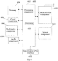
- Fig. 6 is a block diagram of a touch control terminal 600 according to an embodiment of the present invention.
- the touch control terminal 600 may be a mobile phone, a computer, a digital broadcast terminal, a message transceiver, a game console, a tablet device, a medical equipment, a fitness equipment or a personal digital assistance etc.
- the touch control terminal 600 may include one or more of the following components: a processing component 602, a memory 604, a power component 606, a multimedia component 608, an audio component 610, an input/output (I/O) interface 612, a sensor component 614, and a communication component 616.
- the processing component 602 typically controls overall operations of the touch control terminal 600, such as the operations associated with display, telephone calls, data communications, camera operations, and recording operations.
- the processing component 602 may include one or more processors 620 to execute instructions to perform all or part of the steps in the above described methods.
- the processing component 602 may include one or more modules which facilitate the interaction between the processing component 602 and other components.
- the processing component 602 may include a multimedia module to facilitate the interaction between the multimedia component 608 and the processing component 602.
- the memory 604 is configured to store various types of data to support the operation of the touch control terminal 600. Examples of such data include instructions for any applications or methods operated on the touch control terminal 600, contact data, phonebook data, messages, pictures, video, etc.
- the memory 604 may be implemented using any type of volatile or non-volatile memory devices, or a combination thereof, such as a static random access memory (SRAM), an electrically erasable programmable read-only memory (EEPROM), an erasable programmable read-only memory (EPROM), a programmable read-only memory (PROM), a read-only memory (ROM), a magnetic memory, a flash memory, a magnetic or optical disk.
- SRAM static random access memory
- EEPROM electrically erasable programmable read-only memory
- EPROM erasable programmable read-only memory
- PROM programmable read-only memory
- ROM read-only memory
- magnetic memory a magnetic memory
- flash memory a flash memory
- magnetic or optical disk
- the power component 606 provides power to various components of the touch control terminal 600.
- the power component 606 may include a power management system, one or more power sources, and any other components associated with the generation, management, and distribution of power in the touch control terminal 600.
- the multimedia component 608 includes a screen providing an output interface between the touch control terminal 600 and the user.
- the screen may include a liquid crystal display (LCD) and a touch panel (TP). If the screen includes the touch control panel, the screen may be implemented as a touch screen to receive input signals from the user.
- the touch control panel includes one or more touch sensors to sense touches, swipes, and gestures on the touch control panel. The touch sensors may not only sense a boundary of a touch or swipe action, but also sense a period of time and a pressure associated with the touch or swipe action.
- the touch control panel further includes a touch control button.
- the touch control button may be a capacitor button.
- a touch control button area includes the protective layer, the touch sensing layer, the pressure sensing layer and the shielding layer.
- the pressure sensing layer is located below the touch sensing layer, and the shielding layer is located below the pressure sensing layer and at a preset distance from the pressure sensing layer.
- a capacitance is formed between the pressure sensing layer and the shielding layer, when a finger presses the touch control button, the distance between the pressure sensing layer and the shielding layer becomes smaller, such that the electric signal sensed by the pressure sensing layer changes, and the strength of the pressure for pressing the touch control button may be determined according to the change of the electric signal.
- the processing component 602 may perform different operations according to different strengths of pressure.
- the multimedia component 608 includes a front camera and/or a rear camera.
- the front camera and the rear camera may receive an external multimedia datum while the touch control terminal 600 is in an operation mode, such as a photographing mode or a video mode.
- Each of the front camera and the rear camera may be a fixed optical lens system or have focus and optical zoom capability.
- the audio component 610 is configured to output and/or input audio signals.
- the audio component 610 includes a microphone ("MIC") configured to receive an external audio signal when the touch control terminal 600 is in an operation mode, such as a call mode, a recording mode, and a voice recognition mode.
- the received audio signal may be further stored in the memory 604 or transmitted via the communication component 616.
- the audio component 610 further includes a speaker to output audio signals.
- the I/O interface 612 provides an interface between the processing component 602 and peripheral interface modules, such as a keyboard, a click wheel, buttons, and the like.
- the buttons may include, but are not limited to, a home button, a volume button, a starting button, and a locking button.
- the sensor component 614 includes one or more sensors to provide status assessments of various aspects of the touch control terminal 600. For instance, the sensor component 614 may detect an open/closed status of the touch control terminal 600, relative positioning of components, e.g., the display and the keypad, of the touch control terminal 600, a change in position of the touch control terminal 600 or a component of the touch control terminal 600, a presence or absence of user contact with the touch control terminal 600, an orientation or an acceleration/deceleration of the touch control terminal 600, and a change in temperature of the touch control terminal 600.
- the sensor component 614 may include a proximity sensor configured to detect the presence of nearby objects without any physical contact.
- the sensor component 614 may also include a light sensor, such as a CMOS or CCD image sensor, for use in imaging applications.
- the sensor component 614 may also include an accelerometer sensor, a gyroscope sensor, a magnetic sensor, a pressure sensor, or a temperature sensor.
- the communication component 616 is configured to facilitate communication, wired or wirelessly, between the touch control terminal 600 and other devices.
- the touch control terminal 600 can access a wireless network based on a communication standard, such as WiFi, 2G, or 3G, or a combination thereof.
- the communication component 616 receives a broadcast signal or broadcast associated information from an external broadcast management system via a broadcast channel.
- the communication component 616 further includes a near field communication (NFC) module to facilitate short-range communications.
- the NFC module may be implemented based on a radio frequency identification (RFID) technology, an infrared data association (IrDA) technology, an ultra-wideband (UWB) technology, a Bluetooth (BT) technology, and other technologies.
- RFID radio frequency identification
- IrDA infrared data association
- UWB ultra-wideband
- BT Bluetooth
- the touch control terminal 600 may be implemented with one or more application specific integrated circuits (ASICs), digital signal processors (DSPs), digital signal processing devices (DSPDs), programmable logic devices (PLDs), field programmable gate arrays (FPGAs), controllers, micro-controllers, microprocessors, or other electronic components, for performing the above described methods.
- ASICs application specific integrated circuits
- DSPs digital signal processors
- DSPDs digital signal processing devices
- PLDs programmable logic devices
- FPGAs field programmable gate arrays
- controllers micro-controllers, microprocessors, or other electronic components, for performing the above described methods.
- non-transitory computer-readable storage medium including instructions, such as included in the memory 604, executable by the processor 620 in the touch control terminal 600, for performing the above-described methods.
- the non-transitory computer-readable storage medium may be a ROM, a RAM, a CD-ROM, a magnetic tape, a floppy disc, an optical data storage device, and the like.
Landscapes
- Engineering & Computer Science (AREA)
- General Engineering & Computer Science (AREA)
- Theoretical Computer Science (AREA)
- Human Computer Interaction (AREA)
- Physics & Mathematics (AREA)
- General Physics & Mathematics (AREA)
- Position Input By Displaying (AREA)
- User Interface Of Digital Computer (AREA)
Abstract
Description
- The present invention relates to a computer technology field, and more particularly to a touch control button, a touch control panel and a touch control terminal.
- With the pressure sensitive control technology, a pressing strength is sensed by a pressure sensitive control device, and thus feedbacks may be provided in response to touch control actions belonging to three aspects such as clicking, slight pressing and heavy pressing.
- In the prior art, the pressure sensitive control technology is mainly applied in a view area of a touch control panel. However, for a touch control button out of the view area, the touch control may be realized through a self capacitance or mutual capacitance of a sensing channel independent of the view area, while the pressure sensitive touch control cannot be realized.
- In order to overcome problems existing in the prior art, embodiments of the present invention provide a touch control button, a touch control panel and a touch control terminal.
- In order to solve the above problems, embodiments of the present invention provide technical solutions as follows.
- According to a first aspect, the invention relates to a touch control button. The touch control button comprises a touch sensing layer, a pressure sensing layer and a shielding layer, in which:
- the pressure sensing layer is located right below the touch sensing layer in a touch control button area; and
- the shielding layer is located right below the pressure sensing layer and at a preset distance from the pressure sensing layer.
- The touch control button provided in the first aspect includes the touch sensing layer, the pressure sensing layer and the shielding layer. The pressure sensing layer is right below the touch sensing layer and the shielding layer is right below the pressure sensing layer. When a finger or a touch subject presses on the touch control button, the gap between the pressure sensing layer and the shielding layer becomes smaller, such that the electric signal sensed by the pressure sensing layer changes, and then a strength of the pressure made by the finger or touch subject may be determined according to the change of the electric signal. In this way, apart from the perspective of the "duration" of long press gesture, the human-machine interaction based on the touch control button may be realized from the perspective of the "strength" of pressure, thus enriching levels and usage experience of the human-machine interaction.
- In an embodiment, the shielding layer is directly coated on a body of a touch control terminal right below the pressure sensing layer, in which the touch control terminal is provided with the touch control button; or the shielding layer is a metal body of a touch control terminal provided with the touch control button.
- In an embodiment, the pressure sensing layer is directly attached to a bottom of the touch sensing layer in the touch control button area via conductive adhesive.
- In an embodiment, each of the pressure sensing layer and the shielding layer is made of tin indium oxide, flexible circuit board, or metal film printed on a polyethylene glycol terephthalate material.
- In an embodiment, a flexible conductive board is arranged at an edge of the pressure sensing layer, in which the flexible conductive board is provided with a first kind of bonding pad; and
the touch sensing layer is provided with a second kind of bonding pad electrically connected to a touch control chip at a position corresponding to the first kind of bonding pad. - According to a second aspect, the invention relates to a touch control panel. The touch control panel comprises: a view area and a touch control button area; in which
the touch control area is located in an area independent of the view area;
the view area comprises a display screen, a touch sensing layer on the display screen, and a protective layer on the touch sensing layer;
the touch control button area comprises the protective layer, the touch sensing layer, a pressure sensing layer and a shielding layer;
the pressure sensing layer is located below the touch sensing layer in the touch control button area; and
the shielding layer is located below the pressure sensing layer and at a preset distance from the pressure sensing layer. - In an embodiment, the shielding layer is directly coated on a body of a touch control terminal right below the pressure sensing layer, in which the touch control terminal is provided with the touch control button; or
the shielding layer is a metal body of a touch control terminal provided with the touch control button. - In an embodiment, the pressure sensing layer is directly attached to a bottom of the touch sensing layer in the touch control button area via conductive adhesive.
- In an embodiment, each of the pressure sensing layer and the shielding layer is made of tin indium oxide, flexible circuit board, or metal film printed on a polyethylene glycol terephthalate material.
- In an embodiment, a flexible conductive board is arranged at an edge of the pressure sensing layer, in which the flexible conductive board is provided with a first kind of bonding pad; and
the touch sensing layer is provided with a second kind of bonding pad electrically connected to a touch control chip at a position corresponding to the first kind of bonding pad. - According to a third aspect, the invention relates to a touch control terminal. The touch control terminal comprises: a processor and a touch control panel; in which the touch control panel comprises a view area and a touch control button area independent of the view area;
the view area comprises a display screen, a touch sensing layer on the display screen, and a protective layer on the touch sensing layer;
the touch control button area comprises the protective layer, the touch sensing layer, a pressure sensing layer and a shielding layer; the pressure sensing layer is located below the touch sensing layer in the touch control button area; and the shielding layer is located below the pressure sensing layer and at a preset distance from the pressure sensing layer;
the processor is configured to: - detect a touch control signal on the display screen, and perform a first operation according to the touch control signal; and
- detect a touch pressing signal of the touch control button, and perform a second operation according to the touch pressing signal.
- The technical solutions provided in embodiments of the present invention may have following advantageous effects. The touch control button provided in embodiments of the present invention includes the touch sensing layer, the pressure sensing layer and the shielding layer. The pressure sensing layer is right below the touch sensing layer and the shielding layer is right below the pressure sensing layer. When a finger or a touch subject presses on the touch control button, the gap between the pressure sensing layer and the shielding layer becomes smaller, such that the electric signal sensed by the pressure sensing layer changes, and then a strength of the pressure made by the finger or the touch subject may be determined according to the change of the electric signal. Since the touch control button may be used for realizing the sense of the pressure sensitive touch control of the touch subject, the touch control terminal provided with the touch control button may response to the pressure sensitive touch control action. In this way, apart from the perspective of the "duration" of long press gesture, the human-machine interaction based on the touch control button may be realized from the perspective of the "strength" of pressure, thus enriching levels and usage experience of the human-machine interaction.
- It is to be understood that both the foregoing general description and the following detailed description are exemplary and explanatory only and are not restrictive of the invention.
- Accompanying drawings herein are incorporated in and constitute a part of the specification, and illustrate example embodiments in line with the present invention, and serve to explain the principle of the present invention together with the description.
-
Fig. 1 is a schematic diagram of a touch control terminal provided with a touch control button in the prior art. -
Fig. 2 is a section view of a touch control button according to an example embodiment. -
Fig. 3 is a section view of another touch control button according to an example embodiment. -
Fig. 4 is a section view of a touch control panel according to an example embodiment. -
Fig. 5 is a schematic diagram illustrating wires of a pressure sensing layer according to an example embodiment. -
Fig. 6 is a schematic diagram of a touch control terminal according to an example embodiment. - Embodiments of the present invention are illustrated in the above accompany drawings and will be described in further detail hereinafter. These accompany drawings and literal description are not intended to limit the scope of the idea of the present invention, but to explain the principle of the present invention with reference to particular embodiments for those skilled in the art.
- Reference will now be made in detail to exemplary embodiments, examples of which are illustrated in the accompanying drawings. The following description refers to the accompanying drawings in which the same numbers in different drawings represent the same or similar elements unless otherwise represented. The implementations set forth in the following description of exemplary embodiments do not represent all implementations consistent with the invention. Instead, they are merely examples of apparatuses and methods consistent with aspects related to the invention as recited in the appended claims.
- The present invention is explained in combination with
Fig. 1 and Fig. 2 , in whichFig. 1 is a schematic diagram of a touch control terminal provided with a touch control button in the prior art, andFig. 2 is a section view of a touch control button according to an example embodiment. - As shown in
Fig. 1 , atouch control panel 100 on atouch control terminal 110 includes a view area (VA) 111 and a touchcontrol button area 112 independent of the view area. The touch control button area may realize the touch control via a self-capacitance or mutual capacitance of an independent sensing channel. - As shown in
Fig. 2 , the touch control button area according to an example embodiment includes atouch sensing layer 210, apressure sensing layer 220 and ashielding layer 230. - The
touch sensing layer 210 is located at the top, and configured to sense a touch operation (such as, clicking, double-clicking, long-pressing, etc.) performed on the touch control button by a touch subject. - The
pressure sensing layer 220 is located right below thetouch sensing layer 210 in the touch control button area. Thepressure sensing layer 220 may be directly attached to a bottom of thetouch sensing layer 210 via conductive adhesive. - The
shielding layer 230 is located right below thepressure sensing layer 220 and at a preset distance from thepressure sensing layer 220. Further, theshielding layer 230 is grounded. Thepressure sensing layer 220 is configured to sense a pressing operation on the touch control button by the touch subject. For example, different operations correspond respectively to different strengths of pressure. - In this embodiment, a distance between the
pressure sensing layer 220 and theshielding layer 230 approximates to the vertical distance between the pressure sensing layer and a body of the touch control terminal that carries the touch control panel. - In an example embodiment of the present invention, as shown in
Fig. 2 , theshielding layer 230 is attached to thebody 200 of the touch control terminal right below the pressure sensing layer. - In another example embodiment of the present invention, if the body carrying the touch control screen is made of metal, as shown in
Fig. 3 , the metal body may be configured as the shielding layer, such that no further shielding layer is required. - Each of the
pressure sensing layer 220 and theshielding layer 230 may be made of any one from indium tin oxide (ITO), flexible printed circuit board (FPC) and a metal film (such as silver) printed on polyethylene terephthalate (PET) base material. Each one of the above materials is easy to acquire and has a low cost, thus the overall cost of the touch control button is low. - A capacitance may be formed between the
pressure sensing layer 220 and theshielding layer 230. When a finger presses the touch control button, the distance between thepressure sensing layer 220 and theshielding layer 230 becomes smaller, such that the electric signal sensed by the pressure sensing layer changes, and the strength of the pressure for pressing the touch control button may be determined according to the change of electric signal. - In addition, a
protective layer 240 is located above thetouch sensing layer 210, and configured to protect respective sensing layers below theprotective layer 240. Theprotective layer 240 is typically reinforced glass. - The touch control button according to this embodiment includes the touch sensing layer, the pressure sensing layer and the shielding layer. The pressure sensing layer is located below the touch sensing layer, and the shielding layer is located below the pressure sensing layer. When a finger or a touch subject presses on the touch control button, the gap between the pressure sensing layer and the shielding layer becomes smaller, such that the electric signal sensed by the pressure sensing layer changes, and the strength of the pressure of the finger or the touch subject may be determined according to the change of the electric signal. Since the touch control button may be used for realizing the sense of pressure sensitive touch control of the touch subject, the touch control terminal provided with the touch control button may response to the pressure sensitive touch control operation. In this way, apart from the perspective of the "duration" of long press gesture, the human-machine interaction based on the touch control button may be realized from the perspective of the "strength" of pressure, thus enriching levels and usage experience of the human-machine interaction.
- Corresponding to the above touch control button, the present invention further provides embodiments of a touch control panel provided with the touch control button.
-
Fig. 4 is a section view of a touch control panel according to an example embodiment. As shown inFig. 4 , the touch control panel includes a view area and a touch control button area. - The view area includes a
display screen 410, atouch sensing layer 420 and aprotective layer 430. Besides theprotective layer 430 and thetouch sensing layer 420, the touch control button area also includes apressure sensing layer 440 and ashielding layer 450. That is, both theprotective layer 430 and thetouch sensing layer 420 may cover the view area and the touch control button area. - In the view area, the
display screen 410 is located at the bottom, thetouch sensing layer 420 is located above thedisplay screen 410, and theprotective layer 430 is located above thetouch sensing layer 420. - In the touch control button area, the
pressure sensing layer 440 is located below thetouch sensing layer 420 in the touch control button area. Theshielding layer 450 is located below thepressure sensing layer 440 and a certain gap is formed therebetween. Theshielding layer 450 is grounded. - In an example embodiment of the present invention, the
shielding layer 450 is attached to a body of atouch control terminal 400 right below thepressure sensing layer 440, in which the touch control terminal is provided with the touch control panel. - In another example embodiment of the present invention, if the body of the touch control terminal provided with the touch control panel, which carries the touch control screen, is made of metal, the metal body may be directly configured as the shielding layer, without the need of adding an additional shielding layer.
- In this embodiment, each of the
pressure sensing layer 440 and theshielding layer 450 may be made of any one of ITO, FPC and a metal film (such as, silver) printed on PET. -
Fig. 5 is a schematic diagram illustrating wires of a pressure sensing layer according to an example embodiment. As shown inFig. 5 , a flexibleconductive board 520 is arranged at an edge of thepressure sensing layer 510, and the flexibleconductive board 520 is provided with a first kind ofbonding pad 550. At the same time, thetouch sensing layer 540 is provided with a second kind ofbonding pad 530 at a position corresponding to the firstkind bonding pad 550. Further, the second kind of bonding pad is connected to a touch control chip via wires of the touch sensing layer. - After the
pressure sensing layer 510 is attached to a bottom of thetouch sensing layer 540, the first kind ofbonding pad 550 is electrically connected to the second kind ofbonding pad 530, such that the wires of thepressure sensing layer 510 are connected to the touch control chip via the wires of thetouch sending layer 540, thus ensuring that the touch control chip can not only detect pressure sensitive touch control operations but also detect touch operations. - The touch control panel according to this embodiment includes the view area and the touch control button area independent of the view area. The touch control button area includes the touch sensing layer, the pressure sensing layer and the shielding layer. The pressure sensing layer is located below the touch sensing layer, and the shielding layer is located below the pressure sensing layer. When a finger or a touch subject presses on the touch control button, the gap between the pressure sensing layer and the shielding layer becomes smaller, such that the electric signal sensed by the pressure sensing layer changes, and the strength of the pressure of the finger or the touch subject may be determined according to the change of the electric signal. Since the touch control button may be used for realizing the sense of pressure sensitive touch control of the touch subject, the touch control terminal provided with the touch control button may response to the pressure sensitive touch control operation. In this way, apart from the perspective of the "duration" of long press gesture, the human-machine interaction based on the touch control button may be realized from the perspective of the "strength" of pressure, thus enriching levels and usage experience of the human-machine interaction.
- With respect to the device in the above embodiments, specific manners for respective modules performing operations have been described in detail in related method embodiments and detailed descriptions thereof are omitted herein.
-
Fig. 6 is a block diagram of atouch control terminal 600 according to an embodiment of the present invention. For example, thetouch control terminal 600 may be a mobile phone, a computer, a digital broadcast terminal, a message transceiver, a game console, a tablet device, a medical equipment, a fitness equipment or a personal digital assistance etc. - Referring to
Fig. 6 , thetouch control terminal 600 may include one or more of the following components: aprocessing component 602, amemory 604, apower component 606, amultimedia component 608, anaudio component 610, an input/output (I/O)interface 612, asensor component 614, and acommunication component 616. - The
processing component 602 typically controls overall operations of thetouch control terminal 600, such as the operations associated with display, telephone calls, data communications, camera operations, and recording operations. Theprocessing component 602 may include one ormore processors 620 to execute instructions to perform all or part of the steps in the above described methods. Moreover, theprocessing component 602 may include one or more modules which facilitate the interaction between theprocessing component 602 and other components. For instance, theprocessing component 602 may include a multimedia module to facilitate the interaction between themultimedia component 608 and theprocessing component 602. - The
memory 604 is configured to store various types of data to support the operation of thetouch control terminal 600. Examples of such data include instructions for any applications or methods operated on thetouch control terminal 600, contact data, phonebook data, messages, pictures, video, etc. Thememory 604 may be implemented using any type of volatile or non-volatile memory devices, or a combination thereof, such as a static random access memory (SRAM), an electrically erasable programmable read-only memory (EEPROM), an erasable programmable read-only memory (EPROM), a programmable read-only memory (PROM), a read-only memory (ROM), a magnetic memory, a flash memory, a magnetic or optical disk. - The
power component 606 provides power to various components of thetouch control terminal 600. Thepower component 606 may include a power management system, one or more power sources, and any other components associated with the generation, management, and distribution of power in thetouch control terminal 600. - The
multimedia component 608 includes a screen providing an output interface between thetouch control terminal 600 and the user. In some embodiments, the screen may include a liquid crystal display (LCD) and a touch panel (TP). If the screen includes the touch control panel, the screen may be implemented as a touch screen to receive input signals from the user. The touch control panel includes one or more touch sensors to sense touches, swipes, and gestures on the touch control panel. The touch sensors may not only sense a boundary of a touch or swipe action, but also sense a period of time and a pressure associated with the touch or swipe action. - In some embodiments, the touch control panel further includes a touch control button. The touch control button may be a capacitor button. A touch control button area includes the protective layer, the touch sensing layer, the pressure sensing layer and the shielding layer. The pressure sensing layer is located below the touch sensing layer, and the shielding layer is located below the pressure sensing layer and at a preset distance from the pressure sensing layer. A capacitance is formed between the pressure sensing layer and the shielding layer, when a finger presses the touch control button, the distance between the pressure sensing layer and the shielding layer becomes smaller, such that the electric signal sensed by the pressure sensing layer changes, and the strength of the pressure for pressing the touch control button may be determined according to the change of the electric signal. Further, the
processing component 602 may perform different operations according to different strengths of pressure. - In some embodiments, the
multimedia component 608 includes a front camera and/or a rear camera. The front camera and the rear camera may receive an external multimedia datum while thetouch control terminal 600 is in an operation mode, such as a photographing mode or a video mode. Each of the front camera and the rear camera may be a fixed optical lens system or have focus and optical zoom capability. - The
audio component 610 is configured to output and/or input audio signals. For example, theaudio component 610 includes a microphone ("MIC") configured to receive an external audio signal when thetouch control terminal 600 is in an operation mode, such as a call mode, a recording mode, and a voice recognition mode. The received audio signal may be further stored in thememory 604 or transmitted via thecommunication component 616. In some embodiments, theaudio component 610 further includes a speaker to output audio signals. - The I/
O interface 612 provides an interface between theprocessing component 602 and peripheral interface modules, such as a keyboard, a click wheel, buttons, and the like. The buttons may include, but are not limited to, a home button, a volume button, a starting button, and a locking button. - The
sensor component 614 includes one or more sensors to provide status assessments of various aspects of thetouch control terminal 600. For instance, thesensor component 614 may detect an open/closed status of thetouch control terminal 600, relative positioning of components, e.g., the display and the keypad, of thetouch control terminal 600, a change in position of thetouch control terminal 600 or a component of thetouch control terminal 600, a presence or absence of user contact with thetouch control terminal 600, an orientation or an acceleration/deceleration of thetouch control terminal 600, and a change in temperature of thetouch control terminal 600. Thesensor component 614 may include a proximity sensor configured to detect the presence of nearby objects without any physical contact. Thesensor component 614 may also include a light sensor, such as a CMOS or CCD image sensor, for use in imaging applications. In some embodiments, thesensor component 614 may also include an accelerometer sensor, a gyroscope sensor, a magnetic sensor, a pressure sensor, or a temperature sensor. - The
communication component 616 is configured to facilitate communication, wired or wirelessly, between thetouch control terminal 600 and other devices. Thetouch control terminal 600 can access a wireless network based on a communication standard, such as WiFi, 2G, or 3G, or a combination thereof. In one exemplary embodiment, thecommunication component 616 receives a broadcast signal or broadcast associated information from an external broadcast management system via a broadcast channel. In one exemplary embodiment, thecommunication component 616 further includes a near field communication (NFC) module to facilitate short-range communications. For example, the NFC module may be implemented based on a radio frequency identification (RFID) technology, an infrared data association (IrDA) technology, an ultra-wideband (UWB) technology, a Bluetooth (BT) technology, and other technologies. - In exemplary embodiments, the
touch control terminal 600 may be implemented with one or more application specific integrated circuits (ASICs), digital signal processors (DSPs), digital signal processing devices (DSPDs), programmable logic devices (PLDs), field programmable gate arrays (FPGAs), controllers, micro-controllers, microprocessors, or other electronic components, for performing the above described methods. - In exemplary embodiments, there is also provided a non-transitory computer-readable storage medium including instructions, such as included in the
memory 604, executable by theprocessor 620 in thetouch control terminal 600, for performing the above-described methods. For example, the non-transitory computer-readable storage medium may be a ROM, a RAM, a CD-ROM, a magnetic tape, a floppy disc, an optical data storage device, and the like. - Other embodiments of the invention will be apparent to those skilled in the art from consideration of the specification and practice of the invention disclosed here. This application is intended to cover any variations, uses, or adaptations of the invention following the general principles thereof and including such departures from the present invention as come within known or customary practice in the art.
Claims (11)
- A touch control button, comprising a touch sensing layer (210; 420; 540), a pressure sensing layer (220; 440; 510) and a shielding layer (230; 450), wherein
the pressure sensing layer (220; 440; 510) is located right below the touch sensing layer (210; 420; 540) in a touch control button area; and
the shielding layer (230; 450) is located right below the pressure sensing layer (220; 440; 510) and at a preset distance from the pressure sensing layer (220; 440; 510). - The touch control button according to claim 1, wherein,
the shielding layer (230; 450) is directly coated on a body (200, 400) of a touch control terminal right below the pressure sensing layer (220; 440; 510), in which the touch control terminal is provided with the touch control button;
or
the shielding layer (230; 450) is a metal body of a touch control terminal provided with the touch control button. - The touch control button according to claim 1, wherein the pressure sensing layer (220; 440; 510) is directly attached to a bottom of the touch sensing layer (210; 420; 540) in the touch control button area via conductive adhesive.
- The touch control button according to claim 1, wherein each of the pressure sensing layer (220; 440; 510) and the shielding layer (230; 450) is made of tin indium oxide, flexible circuit board or metal film printed on a polyethylene glycol terephthalate material.
- The touch control button according to claim 1, wherein,
a flexible conductive board (520) is arranged at an edge of the pressure sensing layer (220; 440; 510), wherein the flexible conductive board (520) is provided with a first kind of bonding pad (550); and
the touch sensing layer (210; 420; 540) is provided with a second kind of bonding pad (530) electrically connected to a touch control chip at a position corresponding to the first kind of bonding pad (550). - A touch control panel (100), comprising a view area and a touch control button area, wherein,
the touch control button area is located in an area independent of the view area;
the view area comprises a display screen (410), a touch sensing layer (420; 540) on the display screen (410), and a protective layer (430) on the touch sensing layer (420; 540);
the touch control button area comprises the protective layer (430), the touch sensing layer (420; 540), a pressure sensing layer (440; 510) and a shielding layer (450);
the pressure sensing layer (440; 510) is located below the touch sensing layer (420; 540) in the touch control button area; and
the shielding layer (450) is located below the pressure sensing layer (440; 510) and at a preset distance from the pressure sensing layer (220; 440; 520). - The touch control panel (100) according to claim 6, wherein,
the shielding layer (450) is directly coated on a body (200) of a touch control terminal right below the pressure sensing layer (440; 510), in which the touch control terminal is provided with the touch control button;
or
the shielding layer (450) is a metal body of a touch control terminal provided with the touch control button. - The touch control panel (100) according to claim 6, wherein the pressure sensing layer (440; 510) is directly attached to a bottom of the touch sensing layer (420; 540) in the touch control button area via conductive adhesive.
- The touch control panel (100) according to claim 6, wherein each of the pressure sensing layer (440; 520) and the shielding layer (450) is made of tin indium oxide, flexible circuit board, or metal film printed on a polyethylene glycol terephthalate material.
- The touch control panel (100) according to claim 6, wherein,
a flexible conductive board (520) is arranged at an edge of the pressure sensing layer (440; 510), wherein the flexible conductive board (520) is provided with a first kind of bonding pad (550); and
the touch sensing layer (420; 540) is provided with a second kind of bonding pad (530) electrically connected to a touch control chip at a position corresponding to the first kind of bonding pad (550). - A touch control terminal (600), comprising a processor and a touch control panel (100), wherein,
the touch control panel (100) comprises a view area and a touch control button area independent of the view area;
the view area comprises a display screen (410), a touch sensing layer (420; 540) on the display screen (410), and a protective layer (430) on the touch sensing layer (420; 540);
the touch control button area comprises the protective layer (430), the touch sensing layer (420; 540), a pressure sensing layer (440; 510) and a shielding layer (230; 450); the pressure sensing layer (440; 510) is located below the touch sensing layer (420; 540) in the touch control button area; and the shielding layer (230; 450) is located below the pressure sensing layer (440; 510) and at a preset distance from the pressure sensing layer (220; 440; 520); and
the processor is configured to:detect a touch control signal on the display screen (410), and perform a first operation according to the touch control signal; anddetect a touch pressing signal of the touch control button, and perform a second operation according to the touch pressing signal.
Applications Claiming Priority (1)
| Application Number | Priority Date | Filing Date | Title |
|---|---|---|---|
| CN201510946737.7A CN106855759A (en) | 2015-12-16 | 2015-12-16 | Touch controlled key, contact panel and touch control terminal |
Publications (2)
| Publication Number | Publication Date |
|---|---|
| EP3182256A1 true EP3182256A1 (en) | 2017-06-21 |
| EP3182256B1 EP3182256B1 (en) | 2023-02-08 |
Family
ID=57680058
Family Applications (1)
| Application Number | Title | Priority Date | Filing Date |
|---|---|---|---|
| EP16202966.4A Active EP3182256B1 (en) | 2015-12-16 | 2016-12-08 | Touch control button, touch control panel and touch control terminal |
Country Status (7)
| Country | Link |
|---|---|
| US (1) | US20170177149A1 (en) |
| EP (1) | EP3182256B1 (en) |
| JP (1) | JP2018503883A (en) |
| KR (1) | KR20170127032A (en) |
| CN (1) | CN106855759A (en) |
| RU (1) | RU2678516C1 (en) |
| WO (1) | WO2017101563A1 (en) |
Cited By (1)
| Publication number | Priority date | Publication date | Assignee | Title |
|---|---|---|---|---|
| CN109324714A (en) * | 2018-09-13 | 2019-02-12 | 武汉华星光电半导体显示技术有限公司 | OLED touch-control display panel |
Families Citing this family (4)
| Publication number | Priority date | Publication date | Assignee | Title |
|---|---|---|---|---|
| CN119652965A (en) * | 2017-11-17 | 2025-03-18 | 杭州鸿雁物联技术有限公司 | Event-based triggering of controlled device panels |
| US10661159B2 (en) * | 2018-09-11 | 2020-05-26 | SANE Products, Inc. | Mobile game control system |
| CN112698754B (en) * | 2021-01-07 | 2024-03-22 | 海速芯(杭州)科技有限公司 | Method for realizing touch key under electrified metal shielding net |
| CN114347788B (en) * | 2021-11-30 | 2023-10-13 | 岚图汽车科技有限公司 | Intelligent cabin man-machine interaction key control system based on service |
Citations (5)
| Publication number | Priority date | Publication date | Assignee | Title |
|---|---|---|---|---|
| US20100079404A1 (en) * | 2008-09-30 | 2010-04-01 | Apple Inc. | Movable Track Pad with Added Functionality |
| CN101741931A (en) * | 2008-11-14 | 2010-06-16 | Lg电子株式会社 | Mobile terminal |
| US20110175845A1 (en) * | 2009-11-06 | 2011-07-21 | Sony Corporation | Sensor apparatus and electronic apparatus |
| US20120068965A1 (en) * | 2010-09-17 | 2012-03-22 | Sony Corporation | Sensor apparatus and information processing apparatus |
| US20140028575A1 (en) * | 2012-07-26 | 2014-01-30 | Apple Inc. | Gesture and Touch Input Detection Through Force Sensing |
Family Cites Families (18)
| Publication number | Priority date | Publication date | Assignee | Title |
|---|---|---|---|---|
| BE1007462A3 (en) * | 1993-08-26 | 1995-07-04 | Philips Electronics Nv | Data processing device with touch sensor and power. |
| JP5493739B2 (en) * | 2009-03-19 | 2014-05-14 | ソニー株式会社 | Sensor device and information processing device |
| US9024907B2 (en) * | 2009-04-03 | 2015-05-05 | Synaptics Incorporated | Input device with capacitive force sensor and method for constructing the same |
| KR101145155B1 (en) * | 2010-06-28 | 2012-05-14 | 주식회사 비젼스케이프 | Hybrid Capacitive Function Key |
| CN103176641A (en) * | 2011-12-25 | 2013-06-26 | 宸鸿科技(厦门)有限公司 | Touch panel and manufacturing method thereof |
| WO2013107474A1 (en) * | 2012-01-20 | 2013-07-25 | Sony Ericsson Mobile Communications Ab | Touch screen, portable electronic device, and method of operating a touch screen |
| US9264802B2 (en) * | 2012-12-13 | 2016-02-16 | Google Inc. | Computing device utilizing a resting surface as a speaker |
| JP6045924B2 (en) * | 2013-01-28 | 2016-12-14 | シナプティクス・ジャパン合同会社 | Touch panel display device and touch panel controller |
| WO2014162370A1 (en) * | 2013-04-05 | 2014-10-09 | 株式会社カネカ | Optical resin material and optical film |
| CN203276248U (en) * | 2013-05-23 | 2013-11-06 | 福建省辉锐材料科技有限公司 | Touch screen capable of sensing touch positions and pressure |
| CN105094293A (en) * | 2014-05-09 | 2015-11-25 | 敦泰电子有限公司 | Electronic device |
| CN104899494B (en) * | 2015-05-29 | 2017-12-22 | 努比亚技术有限公司 | Method of controlling operation thereof and mobile terminal based on multifunction push key |
| CN204808295U (en) * | 2015-07-14 | 2015-11-25 | 南昌欧菲光科技有限公司 | Touch -control display screen and display device |
| CN105138171B (en) * | 2015-08-28 | 2018-05-08 | 小米科技有限责任公司 | Touch key-press and fingerprint identification method |
| TWI576739B (en) * | 2015-11-05 | 2017-04-01 | 宏碁股份有限公司 | Touch display device and manufacturing method thereof |
| KR102403228B1 (en) * | 2015-12-15 | 2022-05-30 | 삼성디스플레이 주식회사 | Display device |
| CN105739756B (en) * | 2016-01-19 | 2018-12-25 | 北京小米移动软件有限公司 | terminal electronic device |
| CN105760011B (en) * | 2016-01-19 | 2019-01-04 | 北京小米移动软件有限公司 | terminal electronic device |
-
2015
- 2015-12-16 CN CN201510946737.7A patent/CN106855759A/en active Pending
-
2016
- 2016-09-30 WO PCT/CN2016/101190 patent/WO2017101563A1/en not_active Ceased
- 2016-09-30 KR KR1020177030612A patent/KR20170127032A/en not_active Ceased
- 2016-09-30 RU RU2017133785A patent/RU2678516C1/en active
- 2016-09-30 JP JP2017515164A patent/JP2018503883A/en active Pending
- 2016-12-08 EP EP16202966.4A patent/EP3182256B1/en active Active
- 2016-12-15 US US15/379,606 patent/US20170177149A1/en not_active Abandoned
Patent Citations (5)
| Publication number | Priority date | Publication date | Assignee | Title |
|---|---|---|---|---|
| US20100079404A1 (en) * | 2008-09-30 | 2010-04-01 | Apple Inc. | Movable Track Pad with Added Functionality |
| CN101741931A (en) * | 2008-11-14 | 2010-06-16 | Lg电子株式会社 | Mobile terminal |
| US20110175845A1 (en) * | 2009-11-06 | 2011-07-21 | Sony Corporation | Sensor apparatus and electronic apparatus |
| US20120068965A1 (en) * | 2010-09-17 | 2012-03-22 | Sony Corporation | Sensor apparatus and information processing apparatus |
| US20140028575A1 (en) * | 2012-07-26 | 2014-01-30 | Apple Inc. | Gesture and Touch Input Detection Through Force Sensing |
Cited By (1)
| Publication number | Priority date | Publication date | Assignee | Title |
|---|---|---|---|---|
| CN109324714A (en) * | 2018-09-13 | 2019-02-12 | 武汉华星光电半导体显示技术有限公司 | OLED touch-control display panel |
Also Published As
| Publication number | Publication date |
|---|---|
| US20170177149A1 (en) | 2017-06-22 |
| RU2678516C1 (en) | 2019-01-29 |
| WO2017101563A1 (en) | 2017-06-22 |
| JP2018503883A (en) | 2018-02-08 |
| CN106855759A (en) | 2017-06-16 |
| KR20170127032A (en) | 2017-11-20 |
| EP3182256B1 (en) | 2023-02-08 |
Similar Documents
| Publication | Publication Date | Title |
|---|---|---|
| EP3901824B1 (en) | Method and device for realizing touch button and fingerprint identification, and terminal device | |
| EP3163404B1 (en) | Method and device for preventing accidental touch of terminal with touch screen | |
| US9538086B2 (en) | Method of performing previewing and electronic device for implementing the same | |
| EP3301551B1 (en) | Electronic device for identifying touch | |
| US20170031557A1 (en) | Method and apparatus for adjusting shooting function | |
| US9952687B2 (en) | Apparatus for implementing touch control and fingerprint identification and terminal device comprising such apparatus | |
| CN106873834B (en) | Method and device for identifying triggering of key and mobile terminal | |
| EP3130985B1 (en) | Method and device for detecting pressure in mobile terminal | |
| EP3232301B1 (en) | Mobile terminal and virtual key processing method | |
| EP3182256B1 (en) | Touch control button, touch control panel and touch control terminal | |
| EP3136206B1 (en) | Method and apparatus for setting threshold | |
| CN105760011B (en) | terminal electronic device | |
| CN105094609A (en) | Method and device for achieving key operation in single-handed mode | |
| CN105739756A (en) | Terminal electronic device | |
| US10705729B2 (en) | Touch control method and apparatus for function key, and storage medium | |
| CN113867550A (en) | Attitude detection method and device for electronic equipment, storage medium | |
| EP3016236A1 (en) | Power supply circuit and electronic equipment | |
| CN106201108A (en) | Glove control mode touch mode control method and device and electronic equipment | |
| CN107168566B (en) | Operation mode control method, device and terminal electronic device | |
| CN112987958A (en) | Touch signal processing method and device | |
| CN112445363A (en) | Electronic device, control method and device for electronic device, and storage medium | |
| KR102158293B1 (en) | Method for capturing image and electronic device thereof | |
| CN108304124A (en) | Pressure touch inductive terminations, pressure touch inducing method and device, electronic equipment | |
| CN107515694B (en) | Terminal control method and device and terminal | |
| CN108073333B (en) | Touch modules, terminals and electronic equipment |
Legal Events
| Date | Code | Title | Description |
|---|---|---|---|
| PUAI | Public reference made under article 153(3) epc to a published international application that has entered the european phase |
Free format text: ORIGINAL CODE: 0009012 |
|
| STAA | Information on the status of an ep patent application or granted ep patent |
Free format text: STATUS: THE APPLICATION HAS BEEN PUBLISHED |
|
| AK | Designated contracting states |
Kind code of ref document: A1 Designated state(s): AL AT BE BG CH CY CZ DE DK EE ES FI FR GB GR HR HU IE IS IT LI LT LU LV MC MK MT NL NO PL PT RO RS SE SI SK SM TR |
|
| AX | Request for extension of the european patent |
Extension state: BA ME |
|
| STAA | Information on the status of an ep patent application or granted ep patent |
Free format text: STATUS: REQUEST FOR EXAMINATION WAS MADE |
|
| 17P | Request for examination filed |
Effective date: 20171221 |
|
| RBV | Designated contracting states (corrected) |
Designated state(s): AL AT BE BG CH CY CZ DE DK EE ES FI FR GB GR HR HU IE IS IT LI LT LU LV MC MK MT NL NO PL PT RO RS SE SI SK SM TR |
|
| STAA | Information on the status of an ep patent application or granted ep patent |
Free format text: STATUS: EXAMINATION IS IN PROGRESS |
|
| 17Q | First examination report despatched |
Effective date: 20200212 |
|
| GRAP | Despatch of communication of intention to grant a patent |
Free format text: ORIGINAL CODE: EPIDOSNIGR1 |
|
| STAA | Information on the status of an ep patent application or granted ep patent |
Free format text: STATUS: GRANT OF PATENT IS INTENDED |
|
| RIC1 | Information provided on ipc code assigned before grant |
Ipc: H03K 17/975 20060101ALI20220902BHEP Ipc: H03K 17/96 20060101ALI20220902BHEP Ipc: G06F 3/044 20060101ALI20220902BHEP Ipc: G06F 3/041 20060101AFI20220902BHEP |
|
| INTG | Intention to grant announced |
Effective date: 20220921 |
|
| GRAS | Grant fee paid |
Free format text: ORIGINAL CODE: EPIDOSNIGR3 |
|
| GRAA | (expected) grant |
Free format text: ORIGINAL CODE: 0009210 |
|
| STAA | Information on the status of an ep patent application or granted ep patent |
Free format text: STATUS: THE PATENT HAS BEEN GRANTED |
|
| AK | Designated contracting states |
Kind code of ref document: B1 Designated state(s): AL AT BE BG CH CY CZ DE DK EE ES FI FR GB GR HR HU IE IS IT LI LT LU LV MC MK MT NL NO PL PT RO RS SE SI SK SM TR |
|
| REG | Reference to a national code |
Ref country code: GB Ref legal event code: FG4D |
|
| REG | Reference to a national code |
Ref country code: CH Ref legal event code: EP Ref country code: AT Ref legal event code: REF Ref document number: 1547610 Country of ref document: AT Kind code of ref document: T Effective date: 20230215 |
|
| REG | Reference to a national code |
Ref country code: IE Ref legal event code: FG4D |
|
| REG | Reference to a national code |
Ref country code: DE Ref legal event code: R096 Ref document number: 602016077762 Country of ref document: DE |
|
| REG | Reference to a national code |
Ref country code: LT Ref legal event code: MG9D |
|
| REG | Reference to a national code |
Ref country code: NL Ref legal event code: MP Effective date: 20230208 |
|
| P01 | Opt-out of the competence of the unified patent court (upc) registered |
Effective date: 20230523 |
|
| REG | Reference to a national code |
Ref country code: AT Ref legal event code: MK05 Ref document number: 1547610 Country of ref document: AT Kind code of ref document: T Effective date: 20230208 |
|
| PG25 | Lapsed in a contracting state [announced via postgrant information from national office to epo] |
Ref country code: RS Free format text: LAPSE BECAUSE OF FAILURE TO SUBMIT A TRANSLATION OF THE DESCRIPTION OR TO PAY THE FEE WITHIN THE PRESCRIBED TIME-LIMIT Effective date: 20230208 Ref country code: PT Free format text: LAPSE BECAUSE OF FAILURE TO SUBMIT A TRANSLATION OF THE DESCRIPTION OR TO PAY THE FEE WITHIN THE PRESCRIBED TIME-LIMIT Effective date: 20230609 Ref country code: NO Free format text: LAPSE BECAUSE OF FAILURE TO SUBMIT A TRANSLATION OF THE DESCRIPTION OR TO PAY THE FEE WITHIN THE PRESCRIBED TIME-LIMIT Effective date: 20230508 Ref country code: NL Free format text: LAPSE BECAUSE OF FAILURE TO SUBMIT A TRANSLATION OF THE DESCRIPTION OR TO PAY THE FEE WITHIN THE PRESCRIBED TIME-LIMIT Effective date: 20230208 Ref country code: LV Free format text: LAPSE BECAUSE OF FAILURE TO SUBMIT A TRANSLATION OF THE DESCRIPTION OR TO PAY THE FEE WITHIN THE PRESCRIBED TIME-LIMIT Effective date: 20230208 Ref country code: LT Free format text: LAPSE BECAUSE OF FAILURE TO SUBMIT A TRANSLATION OF THE DESCRIPTION OR TO PAY THE FEE WITHIN THE PRESCRIBED TIME-LIMIT Effective date: 20230208 Ref country code: HR Free format text: LAPSE BECAUSE OF FAILURE TO SUBMIT A TRANSLATION OF THE DESCRIPTION OR TO PAY THE FEE WITHIN THE PRESCRIBED TIME-LIMIT Effective date: 20230208 Ref country code: ES Free format text: LAPSE BECAUSE OF FAILURE TO SUBMIT A TRANSLATION OF THE DESCRIPTION OR TO PAY THE FEE WITHIN THE PRESCRIBED TIME-LIMIT Effective date: 20230208 Ref country code: AT Free format text: LAPSE BECAUSE OF FAILURE TO SUBMIT A TRANSLATION OF THE DESCRIPTION OR TO PAY THE FEE WITHIN THE PRESCRIBED TIME-LIMIT Effective date: 20230208 |
|
| PG25 | Lapsed in a contracting state [announced via postgrant information from national office to epo] |
Ref country code: SE Free format text: LAPSE BECAUSE OF FAILURE TO SUBMIT A TRANSLATION OF THE DESCRIPTION OR TO PAY THE FEE WITHIN THE PRESCRIBED TIME-LIMIT Effective date: 20230208 Ref country code: PL Free format text: LAPSE BECAUSE OF FAILURE TO SUBMIT A TRANSLATION OF THE DESCRIPTION OR TO PAY THE FEE WITHIN THE PRESCRIBED TIME-LIMIT Effective date: 20230208 Ref country code: IS Free format text: LAPSE BECAUSE OF FAILURE TO SUBMIT A TRANSLATION OF THE DESCRIPTION OR TO PAY THE FEE WITHIN THE PRESCRIBED TIME-LIMIT Effective date: 20230608 Ref country code: GR Free format text: LAPSE BECAUSE OF FAILURE TO SUBMIT A TRANSLATION OF THE DESCRIPTION OR TO PAY THE FEE WITHIN THE PRESCRIBED TIME-LIMIT Effective date: 20230509 Ref country code: FI Free format text: LAPSE BECAUSE OF FAILURE TO SUBMIT A TRANSLATION OF THE DESCRIPTION OR TO PAY THE FEE WITHIN THE PRESCRIBED TIME-LIMIT Effective date: 20230208 |
|
| PG25 | Lapsed in a contracting state [announced via postgrant information from national office to epo] |
Ref country code: SM Free format text: LAPSE BECAUSE OF FAILURE TO SUBMIT A TRANSLATION OF THE DESCRIPTION OR TO PAY THE FEE WITHIN THE PRESCRIBED TIME-LIMIT Effective date: 20230208 Ref country code: RO Free format text: LAPSE BECAUSE OF FAILURE TO SUBMIT A TRANSLATION OF THE DESCRIPTION OR TO PAY THE FEE WITHIN THE PRESCRIBED TIME-LIMIT Effective date: 20230208 Ref country code: EE Free format text: LAPSE BECAUSE OF FAILURE TO SUBMIT A TRANSLATION OF THE DESCRIPTION OR TO PAY THE FEE WITHIN THE PRESCRIBED TIME-LIMIT Effective date: 20230208 Ref country code: DK Free format text: LAPSE BECAUSE OF FAILURE TO SUBMIT A TRANSLATION OF THE DESCRIPTION OR TO PAY THE FEE WITHIN THE PRESCRIBED TIME-LIMIT Effective date: 20230208 Ref country code: CZ Free format text: LAPSE BECAUSE OF FAILURE TO SUBMIT A TRANSLATION OF THE DESCRIPTION OR TO PAY THE FEE WITHIN THE PRESCRIBED TIME-LIMIT Effective date: 20230208 |
|
| REG | Reference to a national code |
Ref country code: DE Ref legal event code: R097 Ref document number: 602016077762 Country of ref document: DE |
|
| PG25 | Lapsed in a contracting state [announced via postgrant information from national office to epo] |
Ref country code: SK Free format text: LAPSE BECAUSE OF FAILURE TO SUBMIT A TRANSLATION OF THE DESCRIPTION OR TO PAY THE FEE WITHIN THE PRESCRIBED TIME-LIMIT Effective date: 20230208 |
|
| PLBE | No opposition filed within time limit |
Free format text: ORIGINAL CODE: 0009261 |
|
| STAA | Information on the status of an ep patent application or granted ep patent |
Free format text: STATUS: NO OPPOSITION FILED WITHIN TIME LIMIT |
|
| 26N | No opposition filed |
Effective date: 20231109 |
|
| PGFP | Annual fee paid to national office [announced via postgrant information from national office to epo] |
Ref country code: GB Payment date: 20231220 Year of fee payment: 8 |
|
| PG25 | Lapsed in a contracting state [announced via postgrant information from national office to epo] |
Ref country code: SI Free format text: LAPSE BECAUSE OF FAILURE TO SUBMIT A TRANSLATION OF THE DESCRIPTION OR TO PAY THE FEE WITHIN THE PRESCRIBED TIME-LIMIT Effective date: 20230208 |
|
| PGFP | Annual fee paid to national office [announced via postgrant information from national office to epo] |
Ref country code: FR Payment date: 20231221 Year of fee payment: 8 Ref country code: DE Payment date: 20231214 Year of fee payment: 8 |
|
| PG25 | Lapsed in a contracting state [announced via postgrant information from national office to epo] |
Ref country code: IT Free format text: LAPSE BECAUSE OF FAILURE TO SUBMIT A TRANSLATION OF THE DESCRIPTION OR TO PAY THE FEE WITHIN THE PRESCRIBED TIME-LIMIT Effective date: 20230208 |
|
| REG | Reference to a national code |
Ref country code: CH Ref legal event code: PL |
|
| PG25 | Lapsed in a contracting state [announced via postgrant information from national office to epo] |
Ref country code: LU Free format text: LAPSE BECAUSE OF NON-PAYMENT OF DUE FEES Effective date: 20231208 |
|
| PG25 | Lapsed in a contracting state [announced via postgrant information from national office to epo] |
Ref country code: MC Free format text: LAPSE BECAUSE OF FAILURE TO SUBMIT A TRANSLATION OF THE DESCRIPTION OR TO PAY THE FEE WITHIN THE PRESCRIBED TIME-LIMIT Effective date: 20230208 |
|
| REG | Reference to a national code |
Ref country code: BE Ref legal event code: MM Effective date: 20231231 |
|
| PG25 | Lapsed in a contracting state [announced via postgrant information from national office to epo] |
Ref country code: MC Free format text: LAPSE BECAUSE OF FAILURE TO SUBMIT A TRANSLATION OF THE DESCRIPTION OR TO PAY THE FEE WITHIN THE PRESCRIBED TIME-LIMIT Effective date: 20230208 Ref country code: LU Free format text: LAPSE BECAUSE OF NON-PAYMENT OF DUE FEES Effective date: 20231208 |
|
| REG | Reference to a national code |
Ref country code: IE Ref legal event code: MM4A |
|
| PG25 | Lapsed in a contracting state [announced via postgrant information from national office to epo] |
Ref country code: IE Free format text: LAPSE BECAUSE OF NON-PAYMENT OF DUE FEES Effective date: 20231208 |
|
| PG25 | Lapsed in a contracting state [announced via postgrant information from national office to epo] |
Ref country code: BE Free format text: LAPSE BECAUSE OF NON-PAYMENT OF DUE FEES Effective date: 20231231 |
|
| PG25 | Lapsed in a contracting state [announced via postgrant information from national office to epo] |
Ref country code: CH Free format text: LAPSE BECAUSE OF NON-PAYMENT OF DUE FEES Effective date: 20231231 |
|
| PG25 | Lapsed in a contracting state [announced via postgrant information from national office to epo] |
Ref country code: IE Free format text: LAPSE BECAUSE OF NON-PAYMENT OF DUE FEES Effective date: 20231208 Ref country code: CH Free format text: LAPSE BECAUSE OF NON-PAYMENT OF DUE FEES Effective date: 20231231 Ref country code: BE Free format text: LAPSE BECAUSE OF NON-PAYMENT OF DUE FEES Effective date: 20231231 |
|
| PG25 | Lapsed in a contracting state [announced via postgrant information from national office to epo] |
Ref country code: BG Free format text: LAPSE BECAUSE OF FAILURE TO SUBMIT A TRANSLATION OF THE DESCRIPTION OR TO PAY THE FEE WITHIN THE PRESCRIBED TIME-LIMIT Effective date: 20230208 |
|
| PG25 | Lapsed in a contracting state [announced via postgrant information from national office to epo] |
Ref country code: BG Free format text: LAPSE BECAUSE OF FAILURE TO SUBMIT A TRANSLATION OF THE DESCRIPTION OR TO PAY THE FEE WITHIN THE PRESCRIBED TIME-LIMIT Effective date: 20230208 |
|
| REG | Reference to a national code |
Ref country code: DE Ref legal event code: R119 Ref document number: 602016077762 Country of ref document: DE |
|
| PG25 | Lapsed in a contracting state [announced via postgrant information from national office to epo] |
Ref country code: CY Free format text: LAPSE BECAUSE OF FAILURE TO SUBMIT A TRANSLATION OF THE DESCRIPTION OR TO PAY THE FEE WITHIN THE PRESCRIBED TIME-LIMIT; INVALID AB INITIO Effective date: 20161208 |
|
| PG25 | Lapsed in a contracting state [announced via postgrant information from national office to epo] |
Ref country code: HU Free format text: LAPSE BECAUSE OF FAILURE TO SUBMIT A TRANSLATION OF THE DESCRIPTION OR TO PAY THE FEE WITHIN THE PRESCRIBED TIME-LIMIT; INVALID AB INITIO Effective date: 20161208 |
|
| GBPC | Gb: european patent ceased through non-payment of renewal fee |
Effective date: 20241208 |
|
| PG25 | Lapsed in a contracting state [announced via postgrant information from national office to epo] |
Ref country code: DE Free format text: LAPSE BECAUSE OF NON-PAYMENT OF DUE FEES Effective date: 20250701 |
|
| PG25 | Lapsed in a contracting state [announced via postgrant information from national office to epo] |
Ref country code: GB Free format text: LAPSE BECAUSE OF NON-PAYMENT OF DUE FEES Effective date: 20241208 |
|
| PG25 | Lapsed in a contracting state [announced via postgrant information from national office to epo] |
Ref country code: FR Free format text: LAPSE BECAUSE OF NON-PAYMENT OF DUE FEES Effective date: 20241231 |
|
| PG25 | Lapsed in a contracting state [announced via postgrant information from national office to epo] |
Ref country code: TR Free format text: LAPSE BECAUSE OF FAILURE TO SUBMIT A TRANSLATION OF THE DESCRIPTION OR TO PAY THE FEE WITHIN THE PRESCRIBED TIME-LIMIT Effective date: 20230208 |