EP3182035A1 - Compressed air cooling equipment and device - Google Patents
Compressed air cooling equipment and device Download PDFInfo
- Publication number
- EP3182035A1 EP3182035A1 EP16464012.0A EP16464012A EP3182035A1 EP 3182035 A1 EP3182035 A1 EP 3182035A1 EP 16464012 A EP16464012 A EP 16464012A EP 3182035 A1 EP3182035 A1 EP 3182035A1
- Authority
- EP
- European Patent Office
- Prior art keywords
- air
- compressed air
- room
- pressure
- cleaning
- Prior art date
- Legal status (The legal status is an assumption and is not a legal conclusion. Google has not performed a legal analysis and makes no representation as to the accuracy of the status listed.)
- Granted
Links
Images
Classifications
-
- F—MECHANICAL ENGINEERING; LIGHTING; HEATING; WEAPONS; BLASTING
- F25—REFRIGERATION OR COOLING; COMBINED HEATING AND REFRIGERATION SYSTEMS; HEAT PUMP SYSTEMS; MANUFACTURE OR STORAGE OF ICE; LIQUEFACTION SOLIDIFICATION OF GASES
- F25B—REFRIGERATION MACHINES, PLANTS OR SYSTEMS; COMBINED HEATING AND REFRIGERATION SYSTEMS; HEAT PUMP SYSTEMS
- F25B9/00—Compression machines, plants or systems, in which the refrigerant is air or other gas of low boiling point
- F25B9/02—Compression machines, plants or systems, in which the refrigerant is air or other gas of low boiling point using Joule-Thompson effect; using vortex effect
-
- F—MECHANICAL ENGINEERING; LIGHTING; HEATING; WEAPONS; BLASTING
- F25—REFRIGERATION OR COOLING; COMBINED HEATING AND REFRIGERATION SYSTEMS; HEAT PUMP SYSTEMS; MANUFACTURE OR STORAGE OF ICE; LIQUEFACTION SOLIDIFICATION OF GASES
- F25B—REFRIGERATION MACHINES, PLANTS OR SYSTEMS; COMBINED HEATING AND REFRIGERATION SYSTEMS; HEAT PUMP SYSTEMS
- F25B9/00—Compression machines, plants or systems, in which the refrigerant is air or other gas of low boiling point
- F25B9/002—Compression machines, plants or systems, in which the refrigerant is air or other gas of low boiling point characterised by the refrigerant
- F25B9/004—Compression machines, plants or systems, in which the refrigerant is air or other gas of low boiling point characterised by the refrigerant the refrigerant being air
-
- B—PERFORMING OPERATIONS; TRANSPORTING
- B64—AIRCRAFT; AVIATION; COSMONAUTICS
- B64D—EQUIPMENT FOR FITTING IN OR TO AIRCRAFT; FLIGHT SUITS; PARACHUTES; ARRANGEMENT OR MOUNTING OF POWER PLANTS OR PROPULSION TRANSMISSIONS IN AIRCRAFT
- B64D13/00—Arrangements or adaptations of air-treatment apparatus for aircraft crew or passengers, or freight space
- B64D13/02—Arrangements or adaptations of air-treatment apparatus for aircraft crew or passengers, or freight space the air being pressurised
-
- B—PERFORMING OPERATIONS; TRANSPORTING
- B64—AIRCRAFT; AVIATION; COSMONAUTICS
- B64D—EQUIPMENT FOR FITTING IN OR TO AIRCRAFT; FLIGHT SUITS; PARACHUTES; ARRANGEMENT OR MOUNTING OF POWER PLANTS OR PROPULSION TRANSMISSIONS IN AIRCRAFT
- B64D13/00—Arrangements or adaptations of air-treatment apparatus for aircraft crew or passengers, or freight space
- B64D13/06—Arrangements or adaptations of air-treatment apparatus for aircraft crew or passengers, or freight space the air being conditioned
- B64D13/08—Arrangements or adaptations of air-treatment apparatus for aircraft crew or passengers, or freight space the air being conditioned the air being heated or cooled
-
- F—MECHANICAL ENGINEERING; LIGHTING; HEATING; WEAPONS; BLASTING
- F24—HEATING; RANGES; VENTILATING
- F24F—AIR-CONDITIONING; AIR-HUMIDIFICATION; VENTILATION; USE OF AIR CURRENTS FOR SCREENING
- F24F3/00—Air-conditioning systems in which conditioned primary air is supplied from one or more central stations to distributing units in the rooms or spaces where it may receive secondary treatment; Apparatus specially designed for such systems
- F24F3/044—Systems in which all treatment is given in the central station, i.e. all-air systems
-
- F—MECHANICAL ENGINEERING; LIGHTING; HEATING; WEAPONS; BLASTING
- F24—HEATING; RANGES; VENTILATING
- F24F—AIR-CONDITIONING; AIR-HUMIDIFICATION; VENTILATION; USE OF AIR CURRENTS FOR SCREENING
- F24F5/00—Air-conditioning systems or apparatus not covered by F24F1/00 or F24F3/00, e.g. using solar heat or combined with household units such as an oven or water heater
- F24F5/0085—Systems using a compressed air circuit
-
- B—PERFORMING OPERATIONS; TRANSPORTING
- B64—AIRCRAFT; AVIATION; COSMONAUTICS
- B64D—EQUIPMENT FOR FITTING IN OR TO AIRCRAFT; FLIGHT SUITS; PARACHUTES; ARRANGEMENT OR MOUNTING OF POWER PLANTS OR PROPULSION TRANSMISSIONS IN AIRCRAFT
- B64D13/00—Arrangements or adaptations of air-treatment apparatus for aircraft crew or passengers, or freight space
- B64D13/06—Arrangements or adaptations of air-treatment apparatus for aircraft crew or passengers, or freight space the air being conditioned
- B64D2013/0603—Environmental Control Systems
- B64D2013/0651—Environmental Control Systems comprising filters, e.g. dust filters
Definitions
- the invention relates to a dedicated cooling equipment to ensure thermal and physiological comfort inside rooms (enclosures) such as: living space, work space, technological space, the vehicle's passenger compartment.
- the equipment with halogenated refrigerants (chlorofluorocarbon products) is used for cooling enclosures, and consists in: engine, refrigerating compressor, condenser, drain valve, vaporizer etc.
- This equipment has good cooling efficiency, however, since it uses chlorofluorocarbon products, it is causing serious problems for the environment.
- Compressed air cooling equipment is used as well for the background of the invention. Its operation is based on a vortex energy separation effect, known as the Rangue-Hilsch effect.
- the drawback of such equipment is that it simultaneously generates both cold air and hot air, and only one of the fractions is generally used in applications, while the other fraction is dissipated into the atmosphere.
- the problem solved by this invention is the processing of the entire quantity of compressed air, by a pneumatic device, resulting cold air at a temperature below ambient and its use in air conditioning through cooling inside a room/enclosure.
- the operation of the invention is based on the thermodynamic process of compressed air expansion in a centrifugal field and turning it into cold air, harmless for human beings and for the environment.
- the equipment according to the invention eliminates the disadvantages mentioned in that it is composed of a free air suction filter, another suction filter for the air inside the room, two-way and two-position distributor, a turbo-blower or electric air compressor type of source of compressed air, an air-to-air type heat exchanger, a microfilter, a pressure gauge, a pressure relief valve, a pneumatic cooling device based on the thermodynamic effect of expansion in a centrifugal field, silencer, an air disperser, a relief valve for the pressure relief inside the room/enclosure subjected to cooling, a microprocessor module for control.
- the equipment intended for cooling of a room (enclosure) according to the proposed technical solution has the following advantages:
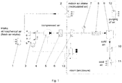
- the equipment schematized in Figure 1 , is comprised of an air filter (1) for cleaning inlet free air, another air filter (2) for cleaning the air sucked from the room, two-way and two-position distributor (3) for switching between indoor air and free air inlet circuit, a turbo-blower or electric air compressor type of source of compressed air (4) for generating low-pressure 2.5 ⁇ 4 bar air, whose cyclic operation is controlled by a microprocessor command module (13), an air-to-air type heat exchanger (5) for removal of heat resulting from air compression, a microfilter (6) for cleaning vitiated air resulting from the compression process, a pressure gauge (7) for viewing circuit pressure value, a pressure relief valve (8) which opens when the pressure in the circuit reaches a preset value in the range 2.5 ⁇ 4 bar, a pneumatic cooling device (9) built with no moving parts where sudden drop in compressed air pressure and an implicit decrease in temperature is caused by the expansion in centrifugal field; a silencer (10) for noise reduction caused by the sudden drop in pressure in
- the operation of the compressed air source (4) in automatic cycles depending on room temperature and time, as well as the position of the distributor (3) is provided by a known microprocessor command module (13).
- Position a-c/open; b/closed, of the distributor (3) allows the installation to process the air inside the room (recirculated air) through cooling, and the position a/closed; b-c/open allows free air (fresh air) processing through cooling.
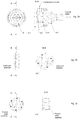
- the pneumatic cooling device (9), as it is represented in fig. 2a, fig. 2b, fig. 2c , for expansion and centrifuging of compressed air (swirling) is built with no moving parts, respectively the device unit (9.1), a multi-jet injector (9.2), a cap (9.3) and a gasket (9.4).
- the multi-jet type injector (9.2), shown in fig. 2b or fig. 2c is fitted with a number of nozzle type holes arranged tangentially to the swirl chamber diameter, in order to divide the incident flow of compressed air, to atomize it and turn it into spray and also reduce the noise resulting from the centrifugal expansion.
- the design of the multi-jet injector (9.2) can be achieved with axial swirl chamber as in fig. 2b , or with frontal swirl chamber as in fig. 2c .
Landscapes
- Engineering & Computer Science (AREA)
- General Engineering & Computer Science (AREA)
- Mechanical Engineering (AREA)
- General Health & Medical Sciences (AREA)
- Combustion & Propulsion (AREA)
- Health & Medical Sciences (AREA)
- Chemical & Material Sciences (AREA)
- Pulmonology (AREA)
- Aviation & Aerospace Engineering (AREA)
- Physics & Mathematics (AREA)
- Thermal Sciences (AREA)
- Sustainable Development (AREA)
- Life Sciences & Earth Sciences (AREA)
- Air-Conditioning For Vehicles (AREA)
- Ventilation (AREA)
Abstract
Description
- The invention relates to a dedicated cooling equipment to ensure thermal and physiological comfort inside rooms (enclosures) such as: living space, work space, technological space, the vehicle's passenger compartment.
- The equipment with halogenated refrigerants (chlorofluorocarbon products) is used for cooling enclosures, and consists in: engine, refrigerating compressor, condenser, drain valve, vaporizer etc. This equipment has good cooling efficiency, however, since it uses chlorofluorocarbon products, it is causing serious problems for the environment.
- Compressed air cooling equipment is used as well for the background of the invention. Its operation is based on a vortex energy separation effect, known as the Rangue-Hilsch effect. The drawback of such equipment is that it simultaneously generates both cold air and hot air, and only one of the fractions is generally used in applications, while the other fraction is dissipated into the atmosphere.
- The problem solved by this invention is the processing of the entire quantity of compressed air, by a pneumatic device, resulting cold air at a temperature below ambient and its use in air conditioning through cooling inside a room/enclosure.
- The operation of the invention is based on the thermodynamic process of compressed air expansion in a centrifugal field and turning it into cold air, harmless for human beings and for the environment.
- The equipment according to the invention eliminates the disadvantages mentioned in that it is composed of a free air suction filter, another suction filter for the air inside the room, two-way and two-position distributor, a turbo-blower or electric air compressor type of source of compressed air, an air-to-air type heat exchanger, a microfilter, a pressure gauge, a pressure relief valve, a pneumatic cooling device based on the thermodynamic effect of expansion in a centrifugal field, silencer, an air disperser, a relief valve for the pressure relief inside the room/enclosure subjected to cooling, a microprocessor module for control.
- The equipment intended for cooling of a room (enclosure) according to the proposed technical solution has the following advantages:
- it turns all compressed air into cold air;
- it provides recirculation of the air in the passenger compartment or inlet of fresh-air and removal of stale air;
- it promotes green technology for the environment, personal health and life;
- Below is an example for the achievement of:
-
Fig. 1 Compressed air cooling equipment -
Fig. 2a Pneumatic cooling device -
Fig. 2b Multi-jet injector with axial swirl chamber -
Fig. 2c Multi-jet injector with frontal swirl chamber - According to the invention, the equipment, schematized in
Figure 1 , is comprised of an air filter (1) for cleaning inlet free air, another air filter (2) for cleaning the air sucked from the room, two-way and two-position distributor (3) for switching between indoor air and free air inlet circuit, a turbo-blower or electric air compressor type of source of compressed air (4) for generating low-pressure 2.5÷4 bar air, whose cyclic operation is controlled by a microprocessor command module (13), an air-to-air type heat exchanger (5) for removal of heat resulting from air compression, a microfilter (6) for cleaning vitiated air resulting from the compression process, a pressure gauge (7) for viewing circuit pressure value, a pressure relief valve (8) which opens when the pressure in the circuit reaches a preset value in the range 2.5÷4 bar, a pneumatic cooling device (9) built with no moving parts where sudden drop in compressed air pressure and an implicit decrease in temperature is caused by the expansion in centrifugal field; a silencer (10) for noise reduction caused by the sudden drop in pressure in the circuit; an air disperser (11) for dispersing cold air in the room; a relief valve (12) which opens automatically and performs purging in the atmosphere only when the pressure in the room reaches a preset threshold value from safety and physiological comfort conditions, a microprocessor command module (13). - The operation of the compressed air source (4) in automatic cycles depending on room temperature and time, as well as the position of the distributor (3) is provided by a known microprocessor command module (13).
- Position a-c/open; b/closed, of the distributor (3) allows the installation to process the air inside the room (recirculated air) through cooling, and the position a/closed; b-c/open allows free air (fresh air) processing through cooling.
- The pneumatic cooling device (9), as it is represented in
fig. 2a, fig. 2b, fig. 2c , for expansion and centrifuging of compressed air (swirling) is built with no moving parts, respectively the device unit (9.1), a multi-jet injector (9.2), a cap (9.3) and a gasket (9.4). The multi-jet type injector (9.2), shown infig. 2b or fig. 2c is fitted with a number of nozzle type holes arranged tangentially to the swirl chamber diameter, in order to divide the incident flow of compressed air, to atomize it and turn it into spray and also reduce the noise resulting from the centrifugal expansion. - The design of the multi-jet injector (9.2) can be achieved with axial swirl chamber as in
fig. 2b , or with frontal swirl chamber as infig. 2c . -
- 1. Patent
RO 122506 B1/2009 - 2. Patent
RO 95442/1988 - 3. Vsevolod Radcenco - Vortex generators for cold and heat. Tehnica Publishing House, Bucharest, 1990.
Claims (2)
- The compressed air cooling equipment characterized by that - in order to ensure thermal and physiological comfort inside living spaces, work spaces, technological spaces, the vehicle's passenger compartment, consists in an air filter (1) for cleaning inlet free air; an air filter (2) for cleaning the air sucked from the room; two-way and two-step distributor (3); a source of compressed air (4); an air-to-air type heat exchanger (5); a microfilter (6) for cleaning vitiated air resulting from the compression process; a pressure gauge (7) ; a pressure relief valve (8) which opens when the pressure in the circuit reaches a preset value in the range 2.5÷4 bar; a pneumatic cooling device (9) generating cold air by expansion in centrifugal field; a silencer (10); an air disperser (11) for dispersing cold air in the room; a pneumatic valve (12) for pressure relieving inside the room; a microprocessor command module (13)
- The compressed air cooling equipment according to requirement no.1, characterized by that - in order to turn all compressed air into cold air with the temperature below ambient, is equipped with a pneumatic cooling device (9), built with no moving parts, respectively the device unit (9.1), a multi-jet injector (9.2), a cap (9.3) and a gasket (9.4). The multi-jet type injector (9.2), is achieved with an axial swirl chamber or frontal swirl chamber and has a number of nozzle type holes arranged tangentially to the swirl chamber diameter.
Applications Claiming Priority (1)
| Application Number | Priority Date | Filing Date | Title |
|---|---|---|---|
| ROA201501016A RO131145B1 (en) | 2015-12-17 | 2015-12-17 | COMPRESSED AIR COOLING DEVICE |
Publications (4)
| Publication Number | Publication Date |
|---|---|
| EP3182035A1 true EP3182035A1 (en) | 2017-06-21 |
| EP3182035B1 EP3182035B1 (en) | 2026-02-11 |
| EP3182035C0 EP3182035C0 (en) | 2026-02-11 |
| EP3182035B8 EP3182035B8 (en) | 2026-03-25 |
Family
ID=56026530
Family Applications (1)
| Application Number | Title | Priority Date | Filing Date |
|---|---|---|---|
| EP16464012.0A Active EP3182035B8 (en) | 2015-12-17 | 2016-12-12 | Compressed air cooling equipment and device |
Country Status (2)
| Country | Link |
|---|---|
| EP (1) | EP3182035B8 (en) |
| RO (1) | RO131145B1 (en) |
Cited By (4)
| Publication number | Priority date | Publication date | Assignee | Title |
|---|---|---|---|---|
| DE102017203769A1 (en) * | 2017-03-08 | 2018-09-13 | Bayerische Motoren Werke Aktiengesellschaft | Compressed air conditioning and procedures |
| CN110715477A (en) * | 2019-11-28 | 2020-01-21 | 广东美的制冷设备有限公司 | Compressed air heat exchange system |
| DE102020004524A1 (en) | 2020-07-22 | 2022-01-27 | Peter Schmitt-Mattern | Refrigerant-free room air conditioning with heat recovery |
| PL240519B1 (en) * | 2020-01-31 | 2022-04-19 | Dac Spolka Z Ograniczona Odpowiedzialnoscia | Cooling unit with dynamic air cooling and the working element of the unit |
Families Citing this family (1)
| Publication number | Priority date | Publication date | Assignee | Title |
|---|---|---|---|---|
| CN113983584B (en) * | 2021-11-16 | 2024-10-18 | 广东信稳能控技术研究有限公司 | Cold and warm environment-friendly movable air conditioner |
Citations (8)
| Publication number | Priority date | Publication date | Assignee | Title |
|---|---|---|---|---|
| US4430867A (en) * | 1981-08-24 | 1984-02-14 | United Technologies Corporation | Air cycle refrigeration system |
| DE3314854A1 (en) * | 1983-04-23 | 1984-10-25 | Bedia Maschinenfabrik Verwaltungs GmbH, 5300 Bonn | Process for the production of cooled conditioning air for the driver's cab of a mine locomotive, and mine locomotive with an arrangement for generating conditioning air |
| RO95442B1 (en) | 1986-11-29 | 1988-09-16 | Institutul De Cercetare Stiintifica Si Inginerie Tehnologica Pentru Industria Electrotehnica | Cooling device |
| GB2237373A (en) * | 1989-10-10 | 1991-05-01 | Aisin Seiki | Air conditioning systems |
| DE4005698A1 (en) * | 1990-02-20 | 1991-08-29 | Mannesmann Ag | Closed space conditioning in motorised plants or vehicles - involves recycling of air through compressor and expander coupled together for electrical or mechanical energy recovery |
| US5461882A (en) * | 1994-07-22 | 1995-10-31 | United Technologies Corporation | Regenerative condensing cycle |
| RO122506B1 (en) | 2007-04-20 | 2009-07-30 | Institutul Naţional De Cercetare-Dezvoltare Şi Încercări Pentru Electrotehnică - Icmet | Ecological conditioning installation |
| CN204478315U (en) * | 2015-03-20 | 2015-07-15 | 杭州盛大高科技机电有限公司 | The new blower fan of a kind of ion with expanding air flue |
Family Cites Families (3)
| Publication number | Priority date | Publication date | Assignee | Title |
|---|---|---|---|---|
| JPH03129267A (en) * | 1989-10-10 | 1991-06-03 | Aisin Seiki Co Ltd | Air conditioner |
| SE508282C2 (en) * | 1995-02-20 | 1998-09-21 | Svenska Rotor Maskiner Ab | Cooling system for air and ways to operate such a system |
| US6966198B2 (en) * | 2003-12-12 | 2005-11-22 | Visteon Global Technologies, Inc. | Air-cycle air conditioning system for commercial refrigeration |
-
2015
- 2015-12-17 RO ROA201501016A patent/RO131145B1/en unknown
-
2016
- 2016-12-12 EP EP16464012.0A patent/EP3182035B8/en active Active
Patent Citations (8)
| Publication number | Priority date | Publication date | Assignee | Title |
|---|---|---|---|---|
| US4430867A (en) * | 1981-08-24 | 1984-02-14 | United Technologies Corporation | Air cycle refrigeration system |
| DE3314854A1 (en) * | 1983-04-23 | 1984-10-25 | Bedia Maschinenfabrik Verwaltungs GmbH, 5300 Bonn | Process for the production of cooled conditioning air for the driver's cab of a mine locomotive, and mine locomotive with an arrangement for generating conditioning air |
| RO95442B1 (en) | 1986-11-29 | 1988-09-16 | Institutul De Cercetare Stiintifica Si Inginerie Tehnologica Pentru Industria Electrotehnica | Cooling device |
| GB2237373A (en) * | 1989-10-10 | 1991-05-01 | Aisin Seiki | Air conditioning systems |
| DE4005698A1 (en) * | 1990-02-20 | 1991-08-29 | Mannesmann Ag | Closed space conditioning in motorised plants or vehicles - involves recycling of air through compressor and expander coupled together for electrical or mechanical energy recovery |
| US5461882A (en) * | 1994-07-22 | 1995-10-31 | United Technologies Corporation | Regenerative condensing cycle |
| RO122506B1 (en) | 2007-04-20 | 2009-07-30 | Institutul Naţional De Cercetare-Dezvoltare Şi Încercări Pentru Electrotehnică - Icmet | Ecological conditioning installation |
| CN204478315U (en) * | 2015-03-20 | 2015-07-15 | 杭州盛大高科技机电有限公司 | The new blower fan of a kind of ion with expanding air flue |
Non-Patent Citations (1)
| Title |
|---|
| VSEVOLOD RADCENCO: "Vortex generators for cold and heat", 1990, TEHNICA PUBLISHING HOUSE |
Cited By (4)
| Publication number | Priority date | Publication date | Assignee | Title |
|---|---|---|---|---|
| DE102017203769A1 (en) * | 2017-03-08 | 2018-09-13 | Bayerische Motoren Werke Aktiengesellschaft | Compressed air conditioning and procedures |
| CN110715477A (en) * | 2019-11-28 | 2020-01-21 | 广东美的制冷设备有限公司 | Compressed air heat exchange system |
| PL240519B1 (en) * | 2020-01-31 | 2022-04-19 | Dac Spolka Z Ograniczona Odpowiedzialnoscia | Cooling unit with dynamic air cooling and the working element of the unit |
| DE102020004524A1 (en) | 2020-07-22 | 2022-01-27 | Peter Schmitt-Mattern | Refrigerant-free room air conditioning with heat recovery |
Also Published As
| Publication number | Publication date |
|---|---|
| RO131145B1 (en) | 2022-11-29 |
| EP3182035B1 (en) | 2026-02-11 |
| EP3182035C0 (en) | 2026-02-11 |
| EP3182035B8 (en) | 2026-03-25 |
| RO131145A0 (en) | 2016-05-30 |
Similar Documents
| Publication | Publication Date | Title |
|---|---|---|
| EP3182035A1 (en) | Compressed air cooling equipment and device | |
| CN107120793B (en) | Variable frequency air conditioner and condensation prevention control method for variable frequency module radiator thereof | |
| CN109140815B (en) | Thermal management system and flow control device | |
| CN111452944A (en) | Ship's anti-epidemic air-conditioning system and its use method | |
| CN212869983U (en) | Air conditioner indoor unit and air conditioner | |
| WO2017206114A1 (en) | Power box for electrical engineering | |
| EP2681979B1 (en) | Cooling device, in particular air-conditioning unit for a computer system | |
| CN203615521U (en) | Air conditioning unit with electrical protection function | |
| KR20130084041A (en) | Combining form air conditioning system and operating method thereof | |
| CN102887228A (en) | Refrigeration air conditioner for helicopter | |
| CN102294085A (en) | Breather working method and comprehensive regulation breather | |
| CN212047849U (en) | Ship Epidemic Prevention Air Conditioning System | |
| CN105620758A (en) | Air refrigeration circulating device with small ram air flow | |
| CN102914014A (en) | Heat pump air-conditioning system | |
| CN111998451A (en) | Circulation system of environmental control device | |
| CN205316470U (en) | Multifunctional air -conditioning unit | |
| CN208671187U (en) | An integrated horizontal air conditioning unit | |
| CN202078671U (en) | Comprehensive adjusting respirator | |
| CN208222899U (en) | A kind of noise is small and the vortex tube cooling gun of good heat dissipation effect | |
| CN106322582A (en) | Central air conditioner with purification function | |
| EP3505844B1 (en) | Air conditioner with plural vanes | |
| CN112848844A (en) | Environment control system for vehicle | |
| MX2015011082A (en) | A motor vehicle having a charge air cooler. | |
| CN208715490U (en) | A kind of helicopter short limb with condenser assembly | |
| CN219583905U (en) | Vehicle-mounted overpressure protection and air conditioner integrated system |
Legal Events
| Date | Code | Title | Description |
|---|---|---|---|
| STAA | Information on the status of an ep patent application or granted ep patent |
Free format text: STATUS: UNKNOWN |
|
| PUAI | Public reference made under article 153(3) epc to a published international application that has entered the european phase |
Free format text: ORIGINAL CODE: 0009012 |
|
| STAA | Information on the status of an ep patent application or granted ep patent |
Free format text: STATUS: REQUEST FOR EXAMINATION WAS MADE |
|
| 17P | Request for examination filed |
Effective date: 20170308 |
|
| AK | Designated contracting states |
Kind code of ref document: A1 Designated state(s): AL AT BE BG CH CY CZ DE DK EE ES FI FR GB GR HR HU IE IS IT LI LT LU LV MC MK MT NL NO PL PT RO RS SE SI SK SM TR |
|
| AX | Request for extension of the european patent |
Extension state: BA ME |
|
| STAA | Information on the status of an ep patent application or granted ep patent |
Free format text: STATUS: EXAMINATION IS IN PROGRESS |
|
| 17Q | First examination report despatched |
Effective date: 20200608 |
|
| GRAP | Despatch of communication of intention to grant a patent |
Free format text: ORIGINAL CODE: EPIDOSNIGR1 |
|
| STAA | Information on the status of an ep patent application or granted ep patent |
Free format text: STATUS: GRANT OF PATENT IS INTENDED |
|
| GRAS | Grant fee paid |
Free format text: ORIGINAL CODE: EPIDOSNIGR3 |
|
| GRAA | (expected) grant |
Free format text: ORIGINAL CODE: 0009210 |
|
| STAA | Information on the status of an ep patent application or granted ep patent |
Free format text: STATUS: THE PATENT HAS BEEN GRANTED |
|
| INTG | Intention to grant announced |
Effective date: 20251215 |
|
| AK | Designated contracting states |
Kind code of ref document: B1 Designated state(s): AL AT BE BG CH CY CZ DE DK EE ES FI FR GB GR HR HU IE IS IT LI LT LU LV MC MK MT NL NO PL PT RO RS SE SI SK SM TR |
|
| REG | Reference to a national code |
Ref country code: CH Ref legal event code: F10 Free format text: ST27 STATUS EVENT CODE: U-0-0-F10-F00 (AS PROVIDED BY THE NATIONAL OFFICE) Effective date: 20260211 Ref country code: GB Ref legal event code: FG4D |
|
| GRAT | Correction requested after decision to grant or after decision to maintain patent in amended form |
Free format text: ORIGINAL CODE: EPIDOSNCDEC |
|
| REG | Reference to a national code |
Ref country code: CH Ref legal event code: Q17 Free format text: ST27 STATUS EVENT CODE: U-0-0-Q10-Q17 (AS PROVIDED BY THE NATIONAL OFFICE) Effective date: 20260225 |
|
| REG | Reference to a national code |
Ref country code: IE Ref legal event code: FG4D |
|
| U01 | Request for unitary effect filed |
Effective date: 20260216 |
|
| U07 | Unitary effect registered |
Designated state(s): AT BE BG DE DK EE FI FR IT LT LU LV MT NL PT RO SE SI Effective date: 20260220 |