EP3181969A1 - Check valve - Google Patents
Check valve Download PDFInfo
- Publication number
- EP3181969A1 EP3181969A1 EP15461583.5A EP15461583A EP3181969A1 EP 3181969 A1 EP3181969 A1 EP 3181969A1 EP 15461583 A EP15461583 A EP 15461583A EP 3181969 A1 EP3181969 A1 EP 3181969A1
- Authority
- EP
- European Patent Office
- Prior art keywords
- leaf spring
- check valve
- flapper
- spring member
- opening
- Prior art date
- Legal status (The legal status is an assumption and is not a legal conclusion. Google has not performed a legal analysis and makes no representation as to the accuracy of the status listed.)
- Granted
Links
Images


Classifications
-
- F—MECHANICAL ENGINEERING; LIGHTING; HEATING; WEAPONS; BLASTING
- F16—ENGINEERING ELEMENTS AND UNITS; GENERAL MEASURES FOR PRODUCING AND MAINTAINING EFFECTIVE FUNCTIONING OF MACHINES OR INSTALLATIONS; THERMAL INSULATION IN GENERAL
- F16K—VALVES; TAPS; COCKS; ACTUATING-FLOATS; DEVICES FOR VENTING OR AERATING
- F16K47/00—Means in valves for absorbing fluid energy
-
- F—MECHANICAL ENGINEERING; LIGHTING; HEATING; WEAPONS; BLASTING
- F16—ENGINEERING ELEMENTS AND UNITS; GENERAL MEASURES FOR PRODUCING AND MAINTAINING EFFECTIVE FUNCTIONING OF MACHINES OR INSTALLATIONS; THERMAL INSULATION IN GENERAL
- F16K—VALVES; TAPS; COCKS; ACTUATING-FLOATS; DEVICES FOR VENTING OR AERATING
- F16K15/00—Check valves
- F16K15/02—Check valves with guided rigid valve members
- F16K15/03—Check valves with guided rigid valve members with a hinged closure member or with a pivoted closure member
- F16K15/035—Check valves with guided rigid valve members with a hinged closure member or with a pivoted closure member with a plurality of valve members
- F16K15/036—Dual valve members with hinges crossing the flow line substantially diametrical
- F16K15/038—Dual valve members with hinges crossing the flow line substantially diametrical having a common hinge
-
- F—MECHANICAL ENGINEERING; LIGHTING; HEATING; WEAPONS; BLASTING
- F16—ENGINEERING ELEMENTS AND UNITS; GENERAL MEASURES FOR PRODUCING AND MAINTAINING EFFECTIVE FUNCTIONING OF MACHINES OR INSTALLATIONS; THERMAL INSULATION IN GENERAL
- F16K—VALVES; TAPS; COCKS; ACTUATING-FLOATS; DEVICES FOR VENTING OR AERATING
- F16K27/00—Construction of housing; Use of materials therefor
- F16K27/02—Construction of housing; Use of materials therefor of lift valves
- F16K27/0209—Check valves or pivoted valves
Definitions
- the present disclosure relates to check valves.
- Check valves are valves that allow fluid flow in one direction therethrough and prevent flow in the opposite direction. They are widely used in a range of applications, for example in air conditioning systems, for example in aircraft air conditioning systems.
- Check valves commonly include a pair of valve elements or flappers located at an opening in a valve housing.
- the flappers are hingedly supported on a hinge pin mounted to the valve housing for rotation between a closed position in which they lie across and close the opening, preventing fluid flow through the opening in one direction and an open position in which, under the pressure of a fluid (gas or liquid) on one side of the check valve, the flappers rotate from their closed positions so as to allow the fluid to flow through the valve in the opposite direction.
- the flappers may be provided with stop elements which, when the flappers move to their open position, engage one another.
- a stop bar is mounted to extend between the flapper elements and spaced from the opening such that when the flappers open, they engage the stop bar.
- the present disclosure relates to a check valve includes a modified stop mechanism.
- a check valve which comprises a valve housing defining a valve opening and a pair of flapper elements pivotably mounted relative to the housing for rotation between an open position in which they permit fluid flow through the opening and a closed position in which they prevent fluid flow through the opening.
- the flapper elements each comprise a first surface facing the opening and a second surface opposite the first surface and facing away from the opening.
- a bowed leaf spring member is mounted to the second surface of each flapper element. The leaf spring members are arranged such that when the flapper elements move towards the closed position, the bowed leaf spring members move into engagement with a respective stop element.
- the leaf spring members are arranged so as to move into engagement with each other.
- the leaf spring member of one flapper element effectively acts as a stop for the other flapper element.
- the leaf spring member comprises a first end and a second end, and both ends of the leaf spring member are translationally fixedly attached to the respective flapper element.
- the leaf spring member comprises a first end and a second end, and one end of the leaf spring member is translationally fixedly attached to the respective flapper element and the other end of the leaf spring member is mounted so as to allow that end of the leaf spring member to translate relative to the second surface of the respective flapper element.
- the leaf spring member comprises a first end and a second end, and both ends of the leaf spring member are mounted so as to allow both ends of the leaf spring member to translate relative to the second surface of the respective flapper element.
- the translationally fixed attachment between the leaf spring member and flapper element may comprise a hinge pin mounted to the second surface of the respective flapper element, the respective end of the leaf spring member being pivotally mounted to hinge pin.
- the translational attachment between the leaf spring member and flapper element may comprise a pin mounted to the second surface of the respective flapper element, with the respective end of the leaf spring member being positioned between the pin and the second surface.
- the translationally movable end(s) of the leaf spring member may be convexly curved in the direction of the second surface of the respective flapper element.
- the respective leaf spring member may be mounted to extend perpendicularly to the pivot axis of the flapper elements. In other arrangements, the leaf spring member may be parallel to the pivot axis.
- a single leaf spring member may be provided on each flapper element, for example generally centrally thereon.
- the leaf spring members may extend generally along a diameter of the valve.
- a backstop may be provided in certain embodiments, to prevent over-rotation of the flapper elements.
- the backstop may be provided on at least one post of a pair of posts of the valve housing arranged at opposed sides of the valve opening and supporting a hinge pin for the flapper elements.
- the check valve 2 comprises a valve housing 4.
- the valve housing 4 defines an opening 6 therethrough in the form of two generally D-shaped apertures (see Figure 4 ) separated by a central web 8 of the valve housing 4.
- the opening is closed by a pair of generally D-shaped flapper elements 10.
- the flapper elements 10 are mounted to a hinge pin 12 which are in turn mounted to mounting posts 14 which extend upwardly from the valve housing 4 on opposed sides of the valve opening 6.
- Respective, tapering backstops 16 project inwardly from the respective mounting posts 14, as will be described further below.
- Each flapper element 10 has a first surface 18 which faces the opening 6 and a second surface 20 opposite the first surface 18 and facing away from the opening 6.
- a bowed leaf spring member 22 is mounted to the second surface 20 of each flapper element 10.
- the leaf spring member 22 can be made of any suitable material, for example a metal, for example stainless steel, nickel steel and so on, depending on the intended operating environment of the check vale 2.
- the leaf spring members 22 extend generally perpendicularly to the pivotal axis of the flapper elements 10 defined by the hinge pin 12 and are arranged centrally on each flapper element 10 such that they lie on a diameter of the check valve 2.
- the leaf spring members 22 are aligned such that when the flapper elements 10 are in a closed position, the leaf spring elements 22 engage (as shown in Figure 3 ).
- Each leaf spring 22 has a first end 24 which is hingedly attached to the respective flapper element 10 and a second end 26.
- the first end 26 of the leaf spring 20 is translationally fixed relative to the associated flapper element 10 and extends pivotally around a first spring mounting pin 28 which is mounted between a first pair of lugs 30 projecting from the second surface 20 of the flapper element 10.
- the pin 28 may be formed integrally with the lugs 30, and the pin 28 need not be circular in cross section. The term pin should therefore be construed broadly in this context.
- the second end 28 of the leaf spring 20 is convexly curved towards the second surface 20 of the flapper element 10 to provide a smooth engagement with that second surface 20.
- the curved section extends loosely under a second spring mounting pin 32 which is mounted between a second pair of lugs 34 projecting from the second surface 20 of the flapper element 10.
- the pin 32 may be formed integrally with the lugs 34, and the pin 32 need not be circular in cross section. This mounting will allow the curved second end 28 of the leaf spring element 22 to slide or translate along the second surface 20 of the flapper element 10.
- the first, translationally fixed end 26 of the leaf spring member 22 is arranged towards the pivotal axis of the flapper10, and the translationally free, second end 26 arranged remote from the pivotal axis. In other embodiments, however, they may be arranged the other way around.
- leaf spring elements 22 are retained on the flapper elements 10 such that when they are pressed inwardly (i.e. towards the second surface 20) between their first and second ends 24, 26, they will be able to deform such that the second end 26 of the leaf spring element 22 will be able to translate or slide along the second surface 20 of the flapper element 10 as the leaf spring element 22 flattens out.
- each respective leaf spring elements act 22 as respective stops for the other flapper element 10.
- leaf spring elements 22 As the leaf spring elements 22 come into contact, they will deform and tend to flatten out as described above. This acts to reduce the impact of the flapper elements 10 with one another or with a stop element and absorbs at least some of the impact energy. Moreover, the translationally free mounting of the second end 26 of the leaf spring member 22 advantageously allows the energy to be dissipated by friction with the flapper element 10.
- check valve 2' A second embodiment of check valve 2' will now be described with reference to Figures 4 to 6 .
- the general construction of the check valve 2' is similar to that of the first embodiment, and only the differences over the first embodiment will be described.
- both ends 24, 26 of the leaf spring element 22 are translationally fixed, with impact energy being absorbed by the resilient engagement of the leaf spring members 22.
- both ends 24, 26 of the leaf spring element 22 may be loosely retained as described in respect of the second end 26 of the leaf spring member 22 of the first embodiment described above.
- Such an arrangement may have the advantage of improved impact energy absorption, but may not provide such a secure attachment of the leaf spring member 22 to the valve 2.
- the leaf spring elements 22 need not engage with one another, but they may engage with a separate stop element.
- a stop element may be provided on the opposing flapper element 10 or on a separate stop element mounted to the valve housing 6, for example a stop pin extending between the mounting posts 14.
- FIG. 7 and 8 An example of such an embodiment is shown in Figures 7 and 8 .
- the mounting posts 114 are elongated with respect to the mounting posts 14 of the earlier embodiments and mount a stop pin 116 extending therebetween.
- the stop pin 116 acts as a back stop for the flapper elements 10 by virtue of the engagement of the stop pin 116 with the leaf spring elements 22.
- the stop pin 116 may be positioned such that the respective leaf spring elements 22 only contact the stop pin 116 (and not each other).
- the leaf spring elements 22 may engage with each other either before or after either contacts the stop pin 116. In such arrangements, advantageously, the leaf spring members 22 should contact the stop pin 116 first.
- leaf spring ends 26, 28 are attached to the flapper elements 10 in the manner shown in Figure 4 , although it will be appreciated that in other embodiments the leaf spring ends 26, 28 may be attached as shown in the alternative manners discussed above.
- leaf spring member 22 is provided on each flapper element 10. However, this is not essential. Thus in other embodiments the leaf spring members 22 may be arranged parallel to the flapper pivot axis or hinge pin 12 rather than perpendicular to it as illustrated. The leaf spring members 22 could also be arranged at some other angle to the hinge pin 12.
- the leaf spring members 22 are illustrated in the embodiment such that they are substantially aligned with one another along their length when engaged, i.e. they lie in the same plane. However, again this is not essential and the leaf spring members 22 may be arranged in non-parallel planes.
- each flapper element 10
- multiple leaf spring members 22 may be provided.
- respective leaf spring members 22 may be provided at the respective ends of each flapper element 10.
- FIG 9 illustrates such an embodiment.
- two leaf spring members 122 are provided on each flapper element 10 adjacent the mounting posts 14. Otherwise the embodiment is similar to the embodiment of Figures 4 to 6 . Again the leaf spring members 122 may be attached to the flapper elements 10 in any of the manners discussed above.
- Figure 10 illustrates a second such embodiment, in which two leaf spring members 122 are provided on each flapper element 10 adjacent mounting posts 114. In this embodiment, however, a stop pin 116 is provided extending between the mounting posts 114, in a similar manner to the embodiment of Figures 7 and 8 .
Landscapes
- Engineering & Computer Science (AREA)
- General Engineering & Computer Science (AREA)
- Mechanical Engineering (AREA)
- Check Valves (AREA)
Abstract
Description
- The present disclosure relates to check valves.
- Check valves are valves that allow fluid flow in one direction therethrough and prevent flow in the opposite direction. They are widely used in a range of applications, for example in air conditioning systems, for example in aircraft air conditioning systems.
- Check valves commonly include a pair of valve elements or flappers located at an opening in a valve housing. The flappers are hingedly supported on a hinge pin mounted to the valve housing for rotation between a closed position in which they lie across and close the opening, preventing fluid flow through the opening in one direction and an open position in which, under the pressure of a fluid (gas or liquid) on one side of the check valve, the flappers rotate from their closed positions so as to allow the fluid to flow through the valve in the opposite direction.
- In known check valve arrangements, to provide a stop for the rotational movement of the flapper elements as they open, the flappers may be provided with stop elements which, when the flappers move to their open position, engage one another. In other constructions, a stop bar is mounted to extend between the flapper elements and spaced from the opening such that when the flappers open, they engage the stop bar.
- The present disclosure relates to a check valve includes a modified stop mechanism.
- From one aspect, there is disclosed herein a check valve which comprises a valve housing defining a valve opening and a pair of flapper elements pivotably mounted relative to the housing for rotation between an open position in which they permit fluid flow through the opening and a closed position in which they prevent fluid flow through the opening. The flapper elements each comprise a first surface facing the opening and a second surface opposite the first surface and facing away from the opening. A bowed leaf spring member is mounted to the second surface of each flapper element. The leaf spring members are arranged such that when the flapper elements move towards the closed position, the bowed leaf spring members move into engagement with a respective stop element.
- In one embodiment, the leaf spring members are arranged so as to move into engagement with each other. In this arrangement, the leaf spring member of one flapper element effectively acts as a stop for the other flapper element.
- In one embodiment, the leaf spring member comprises a first end and a second end, and both ends of the leaf spring member are translationally fixedly attached to the respective flapper element.
- In an alternative embodiment, the leaf spring member comprises a first end and a second end, and one end of the leaf spring member is translationally fixedly attached to the respective flapper element and the other end of the leaf spring member is mounted so as to allow that end of the leaf spring member to translate relative to the second surface of the respective flapper element.
- In a yet further embodiment, the leaf spring member comprises a first end and a second end, and both ends of the leaf spring member are mounted so as to allow both ends of the leaf spring member to translate relative to the second surface of the respective flapper element.
- The translationally fixed attachment between the leaf spring member and flapper element may comprise a hinge pin mounted to the second surface of the respective flapper element, the respective end of the leaf spring member being pivotally mounted to hinge pin.
- The translational attachment between the leaf spring member and flapper element may comprise a pin mounted to the second surface of the respective flapper element, with the respective end of the leaf spring member being positioned between the pin and the second surface.
- The translationally movable end(s) of the leaf spring member may be convexly curved in the direction of the second surface of the respective flapper element. The respective leaf spring member may be mounted to extend perpendicularly to the pivot axis of the flapper elements. In other arrangements, the leaf spring member may be parallel to the pivot axis.
- A single leaf spring member may be provided on each flapper element, for example generally centrally thereon.
- The leaf spring members may extend generally along a diameter of the valve.
- A backstop may be provided in certain embodiments, to prevent over-rotation of the flapper elements. In one embodiment, the backstop may be provided on at least one post of a pair of posts of the valve housing arranged at opposed sides of the valve opening and supporting a hinge pin for the flapper elements.
- Some embodiments of the disclosure will now be described by way of example only with reference to the accompanying drawings in which:
-
-
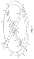
Figure 1 shows a perspective view of a first embodiment of check valve in accordance with this disclosure, in a closed configuration; -
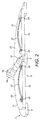
Figure 2 shows a vertical section through the check valve ofFigure 1 ; -
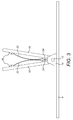
Figure 3 shows a side view of the check valve ofFigure 1 in an open configuration; -
Figure 4 shows a perspective view of a second embodiment of check valve in accordance with this disclosure, in a closed configuration; -
Figure 5 shows a vertical section through the check valve ofFigure 4 ; -
Figure 6 shows a side view of the check valve ofFigure 4 in an open configuration; -
Figure 7 shows a third embodiment of a check valve in accordance with this disclosure, in a closed configuration; -
Figure 8 shows a sectional view of the check valve ofFigure 7 in an open configuration; -
Figure 9 shows a fourth embodiment of a check valve in accordance with this disclosure, in a closed configuration; and -
Figure 10 shows a fifth embodiment of a check valve in accordance with this disclosure, in a closed configuration. - With reference to
Figures 1 to 3 , a first embodiment ofcheck valve 2 in accordance with this disclosure is illustrated. - The
check valve 2 comprises avalve housing 4. Thevalve housing 4 defines an opening 6 therethrough in the form of two generally D-shaped apertures (seeFigure 4 ) separated by acentral web 8 of thevalve housing 4. The opening is closed by a pair of generally D-shaped flapper elements 10. - The
flapper elements 10 are mounted to ahinge pin 12 which are in turn mounted to mountingposts 14 which extend upwardly from thevalve housing 4 on opposed sides of thevalve opening 6. - Respective, tapering
backstops 16 project inwardly from therespective mounting posts 14, as will be described further below. - Each
flapper element 10 has afirst surface 18 which faces theopening 6 and asecond surface 20 opposite thefirst surface 18 and facing away from theopening 6. - A bowed
leaf spring member 22 is mounted to thesecond surface 20 of eachflapper element 10. Theleaf spring member 22 can be made of any suitable material, for example a metal, for example stainless steel, nickel steel and so on, depending on the intended operating environment of thecheck vale 2. - The
leaf spring members 22 extend generally perpendicularly to the pivotal axis of theflapper elements 10 defined by thehinge pin 12 and are arranged centrally on eachflapper element 10 such that they lie on a diameter of thecheck valve 2. Theleaf spring members 22 are aligned such that when theflapper elements 10 are in a closed position, theleaf spring elements 22 engage (as shown inFigure 3 ). - Each
leaf spring 22 has afirst end 24 which is hingedly attached to therespective flapper element 10 and asecond end 26. - The
first end 26 of theleaf spring 20 is translationally fixed relative to the associatedflapper element 10 and extends pivotally around a firstspring mounting pin 28 which is mounted between a first pair oflugs 30 projecting from thesecond surface 20 of theflapper element 10. In other arrangements thepin 28 may be formed integrally with thelugs 30, and thepin 28 need not be circular in cross section. The term pin should therefore be construed broadly in this context. - The
second end 28 of theleaf spring 20 is convexly curved towards thesecond surface 20 of theflapper element 10 to provide a smooth engagement with thatsecond surface 20. The curved section extends loosely under a secondspring mounting pin 32 which is mounted between a second pair oflugs 34 projecting from thesecond surface 20 of theflapper element 10. Again, in other embodiments, thepin 32 may be formed integrally with thelugs 34, and thepin 32 need not be circular in cross section. This mounting will allow the curvedsecond end 28 of theleaf spring element 22 to slide or translate along thesecond surface 20 of theflapper element 10. - In this embodiment, the first, translationally fixed
end 26 of theleaf spring member 22 is arranged towards the pivotal axis of the flapper10, and the translationally free,second end 26 arranged remote from the pivotal axis. In other embodiments, however, they may be arranged the other way around. - It will be apparent from the above that the
leaf spring elements 22 are retained on theflapper elements 10 such that when they are pressed inwardly (i.e. towards the second surface 20) between their first andsecond ends second end 26 of theleaf spring element 22 will be able to translate or slide along thesecond surface 20 of theflapper element 10 as theleaf spring element 22 flattens out. - When the
flapper elements 10 are exposed to a flow of fluid through theopening 6 which opens thevalve 2, theleaf spring elements 22 will come into contact, as shown inFigure 3 . In effect, each respective leaf spring elements act 22 as respective stops for theother flapper element 10. - As the
leaf spring elements 22 come into contact, they will deform and tend to flatten out as described above. This acts to reduce the impact of theflapper elements 10 with one another or with a stop element and absorbs at least some of the impact energy. Moreover, the translationally free mounting of thesecond end 26 of theleaf spring member 22 advantageously allows the energy to be dissipated by friction with theflapper element 10. - It will be appreciated that over-rotation of either
flapper element 10 will be prevented by engagement of theflapper element 10 with thebackstop 16. However, whilst thisbackstop 16 may stop the movement of theflapper elements 10, it will not have to absorb significant impact energy as that will have been done by the engagement of theleaf spring members 22. - A second embodiment of check valve 2' will now be described with reference to
Figures 4 to 6 . The general construction of the check valve 2' is similar to that of the first embodiment, and only the differences over the first embodiment will be described. - In this embodiment, instead of the
second end 26 of theleaf spring member 22 being loosely and slidably retained by the second leaf springmember mounting pin 32, thesecond end 26 extends pivotally around the second leaf springmember mounting pin 32, in the same manner as thefirst end 24 does around the first leafspring mounting pin 28. In this arrangement, therefore, both ends 24, 26 of theleaf spring element 22 are translationally fixed, with impact energy being absorbed by the resilient engagement of theleaf spring members 22. - Other embodiments of the disclosure can also be envisaged. For example in another embodiment, both ends 24, 26 of the
leaf spring element 22 may be loosely retained as described in respect of thesecond end 26 of theleaf spring member 22 of the first embodiment described above. Such an arrangement may have the advantage of improved impact energy absorption, but may not provide such a secure attachment of theleaf spring member 22 to thevalve 2. - In other embodiments, the
leaf spring elements 22 need not engage with one another, but they may engage with a separate stop element. For example a stop element may be provided on the opposingflapper element 10 or on a separate stop element mounted to thevalve housing 6, for example a stop pin extending between the mounting posts 14. - An example of such an embodiment is shown in
Figures 7 and8 . In this embodiment, the mountingposts 114 are elongated with respect to the mountingposts 14 of the earlier embodiments and mount astop pin 116 extending therebetween. Thestop pin 116 acts as a back stop for theflapper elements 10 by virtue of the engagement of thestop pin 116 with theleaf spring elements 22. Thestop pin 116 may be positioned such that the respectiveleaf spring elements 22 only contact the stop pin 116 (and not each other). Alternatively, theleaf spring elements 22 may engage with each other either before or after either contacts thestop pin 116. In such arrangements, advantageously, theleaf spring members 22 should contact thestop pin 116 first. - In the embodiment of
Figures 7 and8 , the leaf spring ends 26, 28 are attached to theflapper elements 10 in the manner shown inFigure 4 , although it will be appreciated that in other embodiments the leaf spring ends 26, 28 may be attached as shown in the alternative manners discussed above. - In the embodiments described above, the same form and orientation of
leaf spring member 22 is provided on eachflapper element 10. However, this is not essential. Thus in other embodiments theleaf spring members 22 may be arranged parallel to the flapper pivot axis orhinge pin 12 rather than perpendicular to it as illustrated. Theleaf spring members 22 could also be arranged at some other angle to thehinge pin 12. - The
leaf spring members 22 are illustrated in the embodiment such that they are substantially aligned with one another along their length when engaged, i.e. they lie in the same plane. However, again this is not essential and theleaf spring members 22 may be arranged in non-parallel planes. - Also, while a single
leaf spring member 22 is provided on eachflapper element 10, in other embodiments multipleleaf spring members 22 may be provided. For example, in some embodiments, respectiveleaf spring members 22 may be provided at the respective ends of eachflapper element 10. -
Figure 9 illustrates such an embodiment. In this embodiment, twoleaf spring members 122 are provided on eachflapper element 10 adjacent the mounting posts 14. Otherwise the embodiment is similar to the embodiment ofFigures 4 to 6 . Again theleaf spring members 122 may be attached to theflapper elements 10 in any of the manners discussed above. -
Figure 10 illustrates a second such embodiment, in which twoleaf spring members 122 are provided on eachflapper element 10 adjacent mounting posts 114. In this embodiment, however, astop pin 116 is provided extending between the mountingposts 114, in a similar manner to the embodiment ofFigures 7 and8 . - It will be understood that the embodiments of the disclosure described above may provide a longer valve life since the impact forces associated with the opening of the
flapper elements 10 are more effectively absorbed by the bowedleaf spring members 22 than in the prior art.
Claims (15)
- A check valve (2) comprising:a valve housing (4) defining a valve opening (6);a pair of flapper elements (10) pivotably mounted relative to the housing (6) for rotation between an open position in which they permit fluid flow through the opening (6) and a closed position in which they prevent fluid flow through the opening (6), each flapper element (10) comprising a first surface (18) facing the opening (6) and a second surface (20) opposite the first surface (18) and facing away from the opening (6); anda bowed leaf spring member (22) mounted to the second surface (20) of each flapper elements (10), the leaf spring members (22) being arranged such that when the flapper elements (10) move towards the closed position, the bowed leaf spring members (22) move into engagement with a respective stop member.
- A check valve as claimed in claim 1, wherein the bowed leaf spring members (22) are arranged such that they move into engagement with each other.
- A check valve as claimed in claim 1 or 2, wherein the leaf spring member (22) comprises a first end (24) and a second end (26), and wherein the first end (24) and the second end (26) are translationally fixedly attached to the respective flapper element (10).
- A check valve as claimed in claim 1 or 2, wherein the leaf spring member (22) comprises a first end (24) and a second end (26), and wherein the first end (24) of the leaf spring member (22) is translationally fixedly attached to the respective flapper element (10) and the second end (26) of the leaf spring member (26) is mounted so as to allow that end (26) to translate relative to the second surface of the respective flapper element (10).
- A check valve as claimed in claim 1 or 2, wherein the leaf spring member (22) comprises a first end (24) and a second end (26), and wherein the first and second ends (24, 26) of the leaf spring member (22) are mounted so as to allow both ends of the leaf spring member to translate relative to the second surface (20) of the respective flapper element (10).
- A check valve as claimed in claim 3 or 4, wherein the translationally fixed attachment of the respective leaf spring member end (24, 26) to the respective flapper element (10) comprises a hinge pin (28) mounted to the second surface (20) of the respective flapper element (10), the end (24, 26) of the leaf spring member (22) being pivotally mounted around the hinge pin (28).
- A check valve as claimed in claim 4 or 5, wherein the translationally free attachment of the leaf spring member end (24, 26) to the respective flapper element (10) comprises a pin (32) mounted to the second surface (20) of the respective flapper element (10), the respective end (24, 26) of the leaf spring member (22) being positioned between the pin (32) and the second surface (20).
- A check valve as claimed in claim 4, 5 or 7, wherein the translationally free end (26) of the leaf spring member (22) is convexly curved in the direction of the second surface (20) of the flapper element (10).
- A check valve as claimed in any preceding claim, wherein the respective leaf spring members (22) are mounted to extend perpendicularly to the pivot axis of the flapper elements (10).
- A check valve as claimed in any of claims 1 to 7, wherein the respective leaf spring members (22) are mounted to extend parallel to the pivot axis of the flapper elements (10).
- A check valve as claimed in any preceding claim, comprising a single leaf spring member (22) provided on each flapper element (10).
- A check valve as claimed in claim 11, wherein the leaf spring members (22) are arranged centrally on the flapper elements (10).
- A check valve as claimed in claim 12 wherein the leaf spring members (22) extend along a diameter of the valve (2).
- A check valve as claimed in any preceding claim, further comprising a backstop (16) for preventing over-rotation of the flapper elements (10).
- A check valve as claimed in claim 14, wherein a backstop (16) is provided on at least one post (14) of the valve housing (6) arranged at opposed sides of the valve opening (6) and supporting a hinge pin (12) for the flapper elements (10).
Priority Applications (2)
| Application Number | Priority Date | Filing Date | Title |
|---|---|---|---|
| EP15461583.5A EP3181969B1 (en) | 2015-12-14 | 2015-12-14 | Check valve |
| US15/378,260 US10309551B2 (en) | 2015-12-14 | 2016-12-14 | Check valves |
Applications Claiming Priority (1)
| Application Number | Priority Date | Filing Date | Title |
|---|---|---|---|
| EP15461583.5A EP3181969B1 (en) | 2015-12-14 | 2015-12-14 | Check valve |
Publications (2)
| Publication Number | Publication Date |
|---|---|
| EP3181969A1 true EP3181969A1 (en) | 2017-06-21 |
| EP3181969B1 EP3181969B1 (en) | 2019-08-07 |
Family
ID=54936964
Family Applications (1)
| Application Number | Title | Priority Date | Filing Date |
|---|---|---|---|
| EP15461583.5A Active EP3181969B1 (en) | 2015-12-14 | 2015-12-14 | Check valve |
Country Status (2)
| Country | Link |
|---|---|
| US (1) | US10309551B2 (en) |
| EP (1) | EP3181969B1 (en) |
Families Citing this family (9)
| Publication number | Priority date | Publication date | Assignee | Title |
|---|---|---|---|---|
| JP6382725B2 (en) * | 2015-01-08 | 2018-08-29 | フタバ産業株式会社 | Exhaust flow path valve device |
| EP3181969B1 (en) * | 2015-12-14 | 2019-08-07 | Hamilton Sundstrand Corporation | Check valve |
| EP3508765B1 (en) | 2018-01-09 | 2021-03-03 | Hamilton Sundstrand Corporation | Check valves |
| CN112096928B (en) * | 2020-08-04 | 2025-05-27 | 南京协威机械有限公司 | A fire-proof guide check valve |
| EP4083478B1 (en) * | 2021-04-27 | 2024-09-18 | UTC Aerospace Systems Wroclaw Sp. z o.o. | Flapper check valve |
| CA3235780A1 (en) | 2021-10-22 | 2023-04-27 | Patrick Hennessey | Ring cutter for safely transecting a ring trapped on an appendage |
| US11828372B2 (en) | 2022-03-31 | 2023-11-28 | General Electric Company | Check valve assembly |
| US20240167576A1 (en) * | 2022-11-17 | 2024-05-23 | Halliburton Energy Services, Inc. | Elastic guided valve |
| USD1089340S1 (en) | 2023-06-22 | 2025-08-19 | Ring Rescue Inc. | Ring cutter |
Citations (3)
| Publication number | Priority date | Publication date | Assignee | Title |
|---|---|---|---|---|
| JP3121513B2 (en) * | 1994-12-14 | 2001-01-09 | 株式会社巴技術研究所 | Dual plate check valve |
| EP1895212A1 (en) * | 2006-08-30 | 2008-03-05 | Honeywell International Inc. | Flapper with insert stops for check valve |
| US20080078458A1 (en) * | 2006-09-29 | 2008-04-03 | Honeywell International, Inc. | Linear damper for check valve |
Family Cites Families (53)
| Publication number | Priority date | Publication date | Assignee | Title |
|---|---|---|---|---|
| US1487038A (en) * | 1920-01-05 | 1924-03-18 | Spencer Turbine Co | Device for controlling valve movements in pressure apparatus |
| US1708907A (en) * | 1927-04-13 | 1929-04-09 | Spencer Turbine Co | Check valve |
| US2898080A (en) * | 1954-07-28 | 1959-08-04 | Techno Corp | Check valve with operator therefor |
| US2877792A (en) * | 1956-10-12 | 1959-03-17 | Frank W Tybus | Surge or back flow valve |
| US3047012A (en) * | 1959-04-16 | 1962-07-31 | Techno Corp | Viscous dampener for valves |
| US3023771A (en) * | 1960-03-08 | 1962-03-06 | John K Hinds | Check valve |
| US3072141A (en) * | 1960-04-15 | 1963-01-08 | Mission Valve And Pump Company | Valve |
| US3166093A (en) * | 1963-03-06 | 1965-01-19 | Arthur J Hopper | Check valve |
| US3208472A (en) * | 1963-07-15 | 1965-09-28 | Scaramucci Domer | Dual flapper check valve |
| US3374804A (en) * | 1965-07-07 | 1968-03-26 | Axel Larsson Maskinaffar Ab | Check valves |
| US3452778A (en) * | 1966-02-18 | 1969-07-01 | Mission Mfg Co | Check valve |
| US3538946A (en) * | 1967-10-09 | 1970-11-10 | George W Hilsheimer | Check valve |
| AT325189B (en) | 1972-06-05 | 1975-10-10 | Hoerbiger Ventilwerke Ag | SELF-ACTING PLATE VALVE |
| US4043358A (en) * | 1976-02-02 | 1977-08-23 | Victaulic Company Of America | Flapper check valve |
| US4094336A (en) * | 1977-04-19 | 1978-06-13 | Urschel John N | Back draft for exhaust fans and hoods |
| US4249567A (en) * | 1979-10-02 | 1981-02-10 | Transamerica Delaval Inc. | Check-valve construction |
| US4457333A (en) * | 1981-05-18 | 1984-07-03 | Transamerica Delaval Inc. | Check valve with relief-valve feature |
| AT398809B (en) | 1987-07-01 | 1995-02-27 | Hoerbiger Ventilwerke Ag | DISC VALVE FOR A COMPRESSOR |
| US4867199A (en) * | 1988-12-14 | 1989-09-19 | Imo Industries, Inc. | Bi-petal l check-valve construction |
| US4896695A (en) * | 1989-05-01 | 1990-01-30 | Pysh Wasyl A | Check valve |
| GB9324697D0 (en) | 1993-12-01 | 1994-01-19 | Goodwin R Int Ltd | Plates for wafer check valves |
| US6237625B1 (en) * | 2000-02-23 | 2001-05-29 | Ronald E. Randolph | Dual plate check valve |
| US6443183B1 (en) | 2000-06-07 | 2002-09-03 | Transcend Inc. | Valve and assembly for axially movable members |
| ES2251492T3 (en) * | 2001-07-10 | 2006-05-01 | Belgicast Internacional, S.L. | SLIM SHIRTS IN LIGHT ALLOY FOR INTERNAL COMBUSTION ENGINE. |
| US7152622B2 (en) | 2004-11-16 | 2006-12-26 | Valve Innovations, Llc | Check valve |
| US8201576B2 (en) * | 2006-04-05 | 2012-06-19 | Klein Gerald A | Reinforced elastomeric hinge check valve |
| US7562669B2 (en) * | 2006-07-31 | 2009-07-21 | Honeywell International Inc. | Check valve stop assembly and method of retention |
| US20080053536A1 (en) * | 2006-08-31 | 2008-03-06 | Honeywell International, Inc. | High flow insert type check valve |
| US20080072973A1 (en) * | 2006-09-25 | 2008-03-27 | Honeywell International, Inc. | Rotary pneumatic damper for check valve |
| US7568498B2 (en) * | 2006-09-26 | 2009-08-04 | Honeywell International Inc. | Engineered composite quiet check valve |
| US20080078459A1 (en) * | 2006-09-29 | 2008-04-03 | Honeywell International, Inc. | Rotary hydraulic damper for check valve |
| US20090056818A1 (en) * | 2007-09-05 | 2009-03-05 | Honeywell International, Inc. | Check valves with noise reducer |
| US8381401B2 (en) | 2009-04-16 | 2013-02-26 | Tenneco Automotive Operating Company Inc. | Method of installing rotatable flapper valve to an interior of a conduit |
| US8181669B2 (en) | 2009-05-06 | 2012-05-22 | Hamilton Sundstrand Corporation | Compliant check valve stop |
| US8726930B2 (en) * | 2012-08-09 | 2014-05-20 | Hamilton Sundstrand Corporation | Dual disk check valve with slotted stop bar |
| US9279509B2 (en) * | 2013-09-09 | 2016-03-08 | Hamilton Sundstrand Corporation | Valve with precision mounted hinge pin posts |
| US9353878B2 (en) * | 2014-02-27 | 2016-05-31 | Melvin Plummer | Dual plate backflow and breakaway check valve |
| US9383023B2 (en) * | 2014-02-27 | 2016-07-05 | Hamilton Sundstrand Corporation | High opening velocity check valve |
| US9347573B2 (en) * | 2014-03-19 | 2016-05-24 | Hamilton Sundstrand Corporation | Check valve with reduced opening speed |
| US9334972B2 (en) * | 2014-05-15 | 2016-05-10 | Honeywell International Inc. | Composite injection molded check valve with integrated features |
| US9581256B2 (en) * | 2014-07-08 | 2017-02-28 | Hamilton Sundstrand Corporation | Valve flapper spring stop mechanism |
| US20160018012A1 (en) * | 2014-07-15 | 2016-01-21 | Hamilton Sundstrand Corporation | Check valve hinge pin |
| US9476515B2 (en) * | 2014-08-06 | 2016-10-25 | Hamilton Sundstrand Corporation | Check valve housing |
| US9464724B2 (en) * | 2014-08-06 | 2016-10-11 | Hamilton Sundstrand Corporation | Check valve flapper |
| US9651160B2 (en) * | 2014-09-24 | 2017-05-16 | Hamilton Sundstrand Corporation | Anti-flutter check valve |
| US20160208939A1 (en) * | 2015-01-20 | 2016-07-21 | United Technologies Corporation | Check valve with clocking and orientation features |
| EP3181969B1 (en) * | 2015-12-14 | 2019-08-07 | Hamilton Sundstrand Corporation | Check valve |
| EP3181964B1 (en) * | 2015-12-14 | 2018-08-22 | Hamilton Sundstrand Corporation | Check valve |
| EP3193054B1 (en) * | 2016-01-14 | 2019-03-06 | Hamilton Sundstrand Corporation | Check valves |
| US9803761B1 (en) * | 2016-04-12 | 2017-10-31 | Hs Wroclaw Sp. Z.O.O. | Flapper check valve bumper |
| EP3258147B1 (en) * | 2016-06-14 | 2023-07-26 | Hamilton Sundstrand Corporation | Check valves |
| EP3258146B1 (en) * | 2016-06-14 | 2020-04-08 | Hamilton Sundstrand Corporation | Check valve |
| EP3415799B1 (en) * | 2017-06-12 | 2020-07-01 | Hamilton Sundstrand Corporation | Check valve housing |
-
2015
- 2015-12-14 EP EP15461583.5A patent/EP3181969B1/en active Active
-
2016
- 2016-12-14 US US15/378,260 patent/US10309551B2/en active Active
Patent Citations (3)
| Publication number | Priority date | Publication date | Assignee | Title |
|---|---|---|---|---|
| JP3121513B2 (en) * | 1994-12-14 | 2001-01-09 | 株式会社巴技術研究所 | Dual plate check valve |
| EP1895212A1 (en) * | 2006-08-30 | 2008-03-05 | Honeywell International Inc. | Flapper with insert stops for check valve |
| US20080078458A1 (en) * | 2006-09-29 | 2008-04-03 | Honeywell International, Inc. | Linear damper for check valve |
Also Published As
| Publication number | Publication date |
|---|---|
| EP3181969B1 (en) | 2019-08-07 |
| US10309551B2 (en) | 2019-06-04 |
| US20170167632A1 (en) | 2017-06-15 |
Similar Documents
| Publication | Publication Date | Title |
|---|---|---|
| EP3181969B1 (en) | Check valve | |
| US11073300B2 (en) | Blast valve utilizing an aerodynamically configured blade | |
| US9835261B2 (en) | Check valves | |
| US10344882B2 (en) | Check valve | |
| US9581256B2 (en) | Valve flapper spring stop mechanism | |
| EP3258146B1 (en) | Check valve | |
| US8726930B2 (en) | Dual disk check valve with slotted stop bar | |
| EP3193059A1 (en) | Check valve | |
| US9347573B2 (en) | Check valve with reduced opening speed | |
| US10612690B2 (en) | Check valves | |
| US9890864B2 (en) | Check valves | |
| US9476515B2 (en) | Check valve housing | |
| US10167974B2 (en) | Check valves | |
| US8714189B2 (en) | Flow valve | |
| US10794502B2 (en) | Check valves | |
| CN114776847B (en) | Check valve | |
| CN214222125U (en) | Stainless steel fire prevention valve | |
| GB2517704A (en) | A damper with improved seal and lock mechanism | |
| CA2819735C (en) | Dual disk check valve with slotted stop bar | |
| GB2410783A (en) | Ventilation valve | |
| BR202016014490U2 (en) | constructive arrangement applied to compressor valve |
Legal Events
| Date | Code | Title | Description |
|---|---|---|---|
| PUAI | Public reference made under article 153(3) epc to a published international application that has entered the european phase |
Free format text: ORIGINAL CODE: 0009012 |
|
| STAA | Information on the status of an ep patent application or granted ep patent |
Free format text: STATUS: THE APPLICATION HAS BEEN PUBLISHED |
|
| AK | Designated contracting states |
Kind code of ref document: A1 Designated state(s): AL AT BE BG CH CY CZ DE DK EE ES FI FR GB GR HR HU IE IS IT LI LT LU LV MC MK MT NL NO PL PT RO RS SE SI SK SM TR |
|
| AX | Request for extension of the european patent |
Extension state: BA ME |
|
| STAA | Information on the status of an ep patent application or granted ep patent |
Free format text: STATUS: REQUEST FOR EXAMINATION WAS MADE |
|
| 17P | Request for examination filed |
Effective date: 20171207 |
|
| RBV | Designated contracting states (corrected) |
Designated state(s): AL AT BE BG CH CY CZ DE DK EE ES FI FR GB GR HR HU IE IS IT LI LT LU LV MC MK MT NL NO PL PT RO RS SE SI SK SM TR |
|
| GRAP | Despatch of communication of intention to grant a patent |
Free format text: ORIGINAL CODE: EPIDOSNIGR1 |
|
| STAA | Information on the status of an ep patent application or granted ep patent |
Free format text: STATUS: GRANT OF PATENT IS INTENDED |
|
| INTG | Intention to grant announced |
Effective date: 20180314 |
|
| GRAS | Grant fee paid |
Free format text: ORIGINAL CODE: EPIDOSNIGR3 |
|
| GRAA | (expected) grant |
Free format text: ORIGINAL CODE: 0009210 |
|
| STAA | Information on the status of an ep patent application or granted ep patent |
Free format text: STATUS: THE PATENT HAS BEEN GRANTED |
|
| AK | Designated contracting states |
Kind code of ref document: B1 Designated state(s): AL AT BE BG CH CY CZ DE DK EE ES FI FR GB GR HR HU IE IS IT LI LT LU LV MC MK MT NL NO PL PT RO RS SE SI SK SM TR |
|
| REG | Reference to a national code |
Ref country code: GB Ref legal event code: FG4D |
|
| REG | Reference to a national code |
Ref country code: CH Ref legal event code: EP Ref country code: AT Ref legal event code: REF Ref document number: 1164407 Country of ref document: AT Kind code of ref document: T Effective date: 20190815 |
|
| REG | Reference to a national code |
Ref country code: DE Ref legal event code: R096 Ref document number: 602015035182 Country of ref document: DE |
|
| REG | Reference to a national code |
Ref country code: IE Ref legal event code: FG4D |
|
| REG | Reference to a national code |
Ref country code: NL Ref legal event code: MP Effective date: 20190807 |
|
| REG | Reference to a national code |
Ref country code: LT Ref legal event code: MG4D |
|
| PG25 | Lapsed in a contracting state [announced via postgrant information from national office to epo] |
Ref country code: FI Free format text: LAPSE BECAUSE OF FAILURE TO SUBMIT A TRANSLATION OF THE DESCRIPTION OR TO PAY THE FEE WITHIN THE PRESCRIBED TIME-LIMIT Effective date: 20190807 Ref country code: HR Free format text: LAPSE BECAUSE OF FAILURE TO SUBMIT A TRANSLATION OF THE DESCRIPTION OR TO PAY THE FEE WITHIN THE PRESCRIBED TIME-LIMIT Effective date: 20190807 Ref country code: PT Free format text: LAPSE BECAUSE OF FAILURE TO SUBMIT A TRANSLATION OF THE DESCRIPTION OR TO PAY THE FEE WITHIN THE PRESCRIBED TIME-LIMIT Effective date: 20191209 Ref country code: SE Free format text: LAPSE BECAUSE OF FAILURE TO SUBMIT A TRANSLATION OF THE DESCRIPTION OR TO PAY THE FEE WITHIN THE PRESCRIBED TIME-LIMIT Effective date: 20190807 Ref country code: LT Free format text: LAPSE BECAUSE OF FAILURE TO SUBMIT A TRANSLATION OF THE DESCRIPTION OR TO PAY THE FEE WITHIN THE PRESCRIBED TIME-LIMIT Effective date: 20190807 Ref country code: BG Free format text: LAPSE BECAUSE OF FAILURE TO SUBMIT A TRANSLATION OF THE DESCRIPTION OR TO PAY THE FEE WITHIN THE PRESCRIBED TIME-LIMIT Effective date: 20191107 Ref country code: NL Free format text: LAPSE BECAUSE OF FAILURE TO SUBMIT A TRANSLATION OF THE DESCRIPTION OR TO PAY THE FEE WITHIN THE PRESCRIBED TIME-LIMIT Effective date: 20190807 Ref country code: NO Free format text: LAPSE BECAUSE OF FAILURE TO SUBMIT A TRANSLATION OF THE DESCRIPTION OR TO PAY THE FEE WITHIN THE PRESCRIBED TIME-LIMIT Effective date: 20191107 |
|
| REG | Reference to a national code |
Ref country code: AT Ref legal event code: MK05 Ref document number: 1164407 Country of ref document: AT Kind code of ref document: T Effective date: 20190807 |
|
| PG25 | Lapsed in a contracting state [announced via postgrant information from national office to epo] |
Ref country code: ES Free format text: LAPSE BECAUSE OF FAILURE TO SUBMIT A TRANSLATION OF THE DESCRIPTION OR TO PAY THE FEE WITHIN THE PRESCRIBED TIME-LIMIT Effective date: 20190807 Ref country code: LV Free format text: LAPSE BECAUSE OF FAILURE TO SUBMIT A TRANSLATION OF THE DESCRIPTION OR TO PAY THE FEE WITHIN THE PRESCRIBED TIME-LIMIT Effective date: 20190807 Ref country code: IS Free format text: LAPSE BECAUSE OF FAILURE TO SUBMIT A TRANSLATION OF THE DESCRIPTION OR TO PAY THE FEE WITHIN THE PRESCRIBED TIME-LIMIT Effective date: 20191207 Ref country code: AL Free format text: LAPSE BECAUSE OF FAILURE TO SUBMIT A TRANSLATION OF THE DESCRIPTION OR TO PAY THE FEE WITHIN THE PRESCRIBED TIME-LIMIT Effective date: 20190807 Ref country code: RS Free format text: LAPSE BECAUSE OF FAILURE TO SUBMIT A TRANSLATION OF THE DESCRIPTION OR TO PAY THE FEE WITHIN THE PRESCRIBED TIME-LIMIT Effective date: 20190807 Ref country code: GR Free format text: LAPSE BECAUSE OF FAILURE TO SUBMIT A TRANSLATION OF THE DESCRIPTION OR TO PAY THE FEE WITHIN THE PRESCRIBED TIME-LIMIT Effective date: 20191108 |
|
| PG25 | Lapsed in a contracting state [announced via postgrant information from national office to epo] |
Ref country code: TR Free format text: LAPSE BECAUSE OF FAILURE TO SUBMIT A TRANSLATION OF THE DESCRIPTION OR TO PAY THE FEE WITHIN THE PRESCRIBED TIME-LIMIT Effective date: 20190807 |
|
| PG25 | Lapsed in a contracting state [announced via postgrant information from national office to epo] |
Ref country code: IT Free format text: LAPSE BECAUSE OF FAILURE TO SUBMIT A TRANSLATION OF THE DESCRIPTION OR TO PAY THE FEE WITHIN THE PRESCRIBED TIME-LIMIT Effective date: 20190807 Ref country code: EE Free format text: LAPSE BECAUSE OF FAILURE TO SUBMIT A TRANSLATION OF THE DESCRIPTION OR TO PAY THE FEE WITHIN THE PRESCRIBED TIME-LIMIT Effective date: 20190807 Ref country code: RO Free format text: LAPSE BECAUSE OF FAILURE TO SUBMIT A TRANSLATION OF THE DESCRIPTION OR TO PAY THE FEE WITHIN THE PRESCRIBED TIME-LIMIT Effective date: 20190807 Ref country code: AT Free format text: LAPSE BECAUSE OF FAILURE TO SUBMIT A TRANSLATION OF THE DESCRIPTION OR TO PAY THE FEE WITHIN THE PRESCRIBED TIME-LIMIT Effective date: 20190807 Ref country code: DK Free format text: LAPSE BECAUSE OF FAILURE TO SUBMIT A TRANSLATION OF THE DESCRIPTION OR TO PAY THE FEE WITHIN THE PRESCRIBED TIME-LIMIT Effective date: 20190807 Ref country code: PL Free format text: LAPSE BECAUSE OF FAILURE TO SUBMIT A TRANSLATION OF THE DESCRIPTION OR TO PAY THE FEE WITHIN THE PRESCRIBED TIME-LIMIT Effective date: 20190807 |
|
| PG25 | Lapsed in a contracting state [announced via postgrant information from national office to epo] |
Ref country code: CZ Free format text: LAPSE BECAUSE OF FAILURE TO SUBMIT A TRANSLATION OF THE DESCRIPTION OR TO PAY THE FEE WITHIN THE PRESCRIBED TIME-LIMIT Effective date: 20190807 Ref country code: SK Free format text: LAPSE BECAUSE OF FAILURE TO SUBMIT A TRANSLATION OF THE DESCRIPTION OR TO PAY THE FEE WITHIN THE PRESCRIBED TIME-LIMIT Effective date: 20190807 Ref country code: SM Free format text: LAPSE BECAUSE OF FAILURE TO SUBMIT A TRANSLATION OF THE DESCRIPTION OR TO PAY THE FEE WITHIN THE PRESCRIBED TIME-LIMIT Effective date: 20190807 Ref country code: IS Free format text: LAPSE BECAUSE OF FAILURE TO SUBMIT A TRANSLATION OF THE DESCRIPTION OR TO PAY THE FEE WITHIN THE PRESCRIBED TIME-LIMIT Effective date: 20200224 |
|
| REG | Reference to a national code |
Ref country code: DE Ref legal event code: R097 Ref document number: 602015035182 Country of ref document: DE |
|
| REG | Reference to a national code |
Ref country code: DE Ref legal event code: R119 Ref document number: 602015035182 Country of ref document: DE |
|
| PLBE | No opposition filed within time limit |
Free format text: ORIGINAL CODE: 0009261 |
|
| STAA | Information on the status of an ep patent application or granted ep patent |
Free format text: STATUS: NO OPPOSITION FILED WITHIN TIME LIMIT |
|
| PG2D | Information on lapse in contracting state deleted |
Ref country code: IS |
|
| REG | Reference to a national code |
Ref country code: CH Ref legal event code: PL |
|
| 26N | No opposition filed |
Effective date: 20200603 |
|
| REG | Reference to a national code |
Ref country code: BE Ref legal event code: MM Effective date: 20191231 |
|
| PG25 | Lapsed in a contracting state [announced via postgrant information from national office to epo] |
Ref country code: MC Free format text: LAPSE BECAUSE OF FAILURE TO SUBMIT A TRANSLATION OF THE DESCRIPTION OR TO PAY THE FEE WITHIN THE PRESCRIBED TIME-LIMIT Effective date: 20190807 Ref country code: SI Free format text: LAPSE BECAUSE OF FAILURE TO SUBMIT A TRANSLATION OF THE DESCRIPTION OR TO PAY THE FEE WITHIN THE PRESCRIBED TIME-LIMIT Effective date: 20190807 |
|
| PG25 | Lapsed in a contracting state [announced via postgrant information from national office to epo] |
Ref country code: DE Free format text: LAPSE BECAUSE OF NON-PAYMENT OF DUE FEES Effective date: 20200701 Ref country code: IE Free format text: LAPSE BECAUSE OF NON-PAYMENT OF DUE FEES Effective date: 20191214 Ref country code: LU Free format text: LAPSE BECAUSE OF NON-PAYMENT OF DUE FEES Effective date: 20191214 |
|
| PG25 | Lapsed in a contracting state [announced via postgrant information from national office to epo] |
Ref country code: CH Free format text: LAPSE BECAUSE OF NON-PAYMENT OF DUE FEES Effective date: 20191231 Ref country code: LI Free format text: LAPSE BECAUSE OF NON-PAYMENT OF DUE FEES Effective date: 20191231 Ref country code: BE Free format text: LAPSE BECAUSE OF NON-PAYMENT OF DUE FEES Effective date: 20191231 |
|
| PG25 | Lapsed in a contracting state [announced via postgrant information from national office to epo] |
Ref country code: CY Free format text: LAPSE BECAUSE OF FAILURE TO SUBMIT A TRANSLATION OF THE DESCRIPTION OR TO PAY THE FEE WITHIN THE PRESCRIBED TIME-LIMIT Effective date: 20190807 |
|
| PG25 | Lapsed in a contracting state [announced via postgrant information from national office to epo] |
Ref country code: HU Free format text: LAPSE BECAUSE OF FAILURE TO SUBMIT A TRANSLATION OF THE DESCRIPTION OR TO PAY THE FEE WITHIN THE PRESCRIBED TIME-LIMIT; INVALID AB INITIO Effective date: 20151214 Ref country code: MT Free format text: LAPSE BECAUSE OF FAILURE TO SUBMIT A TRANSLATION OF THE DESCRIPTION OR TO PAY THE FEE WITHIN THE PRESCRIBED TIME-LIMIT Effective date: 20190807 |
|
| PG25 | Lapsed in a contracting state [announced via postgrant information from national office to epo] |
Ref country code: MK Free format text: LAPSE BECAUSE OF FAILURE TO SUBMIT A TRANSLATION OF THE DESCRIPTION OR TO PAY THE FEE WITHIN THE PRESCRIBED TIME-LIMIT Effective date: 20190807 |
|
| P01 | Opt-out of the competence of the unified patent court (upc) registered |
Effective date: 20230522 |
|
| PGFP | Annual fee paid to national office [announced via postgrant information from national office to epo] |
Ref country code: GB Payment date: 20251119 Year of fee payment: 11 |
|
| PGFP | Annual fee paid to national office [announced via postgrant information from national office to epo] |
Ref country code: FR Payment date: 20251120 Year of fee payment: 11 |