US8726930B2 - Dual disk check valve with slotted stop bar - Google Patents

Dual disk check valve with slotted stop bar Download PDF

Info

Publication number
US8726930B2
US8726930B2 US13/570,926 US201213570926A US8726930B2 US 8726930 B2 US8726930 B2 US 8726930B2 US 201213570926 A US201213570926 A US 201213570926A US 8726930 B2 US8726930 B2 US 8726930B2
Authority
US
United States
Prior art keywords
bars
check valve
mechanical stop
central portion
intermediate sections
Prior art date
Legal status (The legal status is an assumption and is not a legal conclusion. Google has not performed a legal analysis and makes no representation as to the accuracy of the status listed.)
Active
Application number
US13/570,926
Other versions
US20140041739A1 (en
Inventor
Michael Barone
Current Assignee (The listed assignees may be inaccurate. Google has not performed a legal analysis and makes no representation or warranty as to the accuracy of the list.)
Hamilton Sundstrand Corp
Original Assignee
Hamilton Sundstrand Corp
Priority date (The priority date is an assumption and is not a legal conclusion. Google has not performed a legal analysis and makes no representation as to the accuracy of the date listed.)
Filing date
Publication date
Application filed by Hamilton Sundstrand Corp filed Critical Hamilton Sundstrand Corp
Priority to US13/570,926 priority Critical patent/US8726930B2/en
Assigned to HAMILTON SUNDSTRAND CORPORATION reassignment HAMILTON SUNDSTRAND CORPORATION ASSIGNMENT OF ASSIGNORS INTEREST (SEE DOCUMENT FOR DETAILS). Assignors: BARONE, MICHAEL
Priority to FR1356609A priority patent/FR2994469B1/en
Publication of US20140041739A1 publication Critical patent/US20140041739A1/en
Application granted granted Critical
Publication of US8726930B2 publication Critical patent/US8726930B2/en
Active legal-status Critical Current
Anticipated expiration legal-status Critical

Links

Images

Classifications

    • FMECHANICAL ENGINEERING; LIGHTING; HEATING; WEAPONS; BLASTING
    • F16ENGINEERING ELEMENTS AND UNITS; GENERAL MEASURES FOR PRODUCING AND MAINTAINING EFFECTIVE FUNCTIONING OF MACHINES OR INSTALLATIONS; THERMAL INSULATION IN GENERAL
    • F16KVALVES; TAPS; COCKS; ACTUATING-FLOATS; DEVICES FOR VENTING OR AERATING
    • F16K27/00Construction of housing; Use of materials therefor
    • F16K27/02Construction of housing; Use of materials therefor of lift valves
    • F16K27/0209Check valves or pivoted valves
    • F16K27/0227Check valves or pivoted valves with the valve members swinging around an axis located at the edge of or outside the valve member
    • FMECHANICAL ENGINEERING; LIGHTING; HEATING; WEAPONS; BLASTING
    • F16ENGINEERING ELEMENTS AND UNITS; GENERAL MEASURES FOR PRODUCING AND MAINTAINING EFFECTIVE FUNCTIONING OF MACHINES OR INSTALLATIONS; THERMAL INSULATION IN GENERAL
    • F16KVALVES; TAPS; COCKS; ACTUATING-FLOATS; DEVICES FOR VENTING OR AERATING
    • F16K15/00Check valves
    • F16K15/02Check valves with guided rigid valve members
    • F16K15/03Check valves with guided rigid valve members with a hinged closure member or with a pivoted closure member
    • F16K15/035Check valves with guided rigid valve members with a hinged closure member or with a pivoted closure member with a plurality of valve members
    • F16K15/036Dual valve members with hinges crossing the flow line substantially diametrical
    • F16K15/038Dual valve members with hinges crossing the flow line substantially diametrical having a common hinge
    • YGENERAL TAGGING OF NEW TECHNOLOGICAL DEVELOPMENTS; GENERAL TAGGING OF CROSS-SECTIONAL TECHNOLOGIES SPANNING OVER SEVERAL SECTIONS OF THE IPC; TECHNICAL SUBJECTS COVERED BY FORMER USPC CROSS-REFERENCE ART COLLECTIONS [XRACs] AND DIGESTS
    • Y10TECHNICAL SUBJECTS COVERED BY FORMER USPC
    • Y10TTECHNICAL SUBJECTS COVERED BY FORMER US CLASSIFICATION
    • Y10T137/00Fluid handling
    • Y10T137/7722Line condition change responsive valves
    • Y10T137/7837Direct response valves [i.e., check valve type]
    • Y10T137/7838Plural
    • Y10T137/7839Dividing and recombining in a single flow path
    • YGENERAL TAGGING OF NEW TECHNOLOGICAL DEVELOPMENTS; GENERAL TAGGING OF CROSS-SECTIONAL TECHNOLOGIES SPANNING OVER SEVERAL SECTIONS OF THE IPC; TECHNICAL SUBJECTS COVERED BY FORMER USPC CROSS-REFERENCE ART COLLECTIONS [XRACs] AND DIGESTS
    • Y10TECHNICAL SUBJECTS COVERED BY FORMER USPC
    • Y10TTECHNICAL SUBJECTS COVERED BY FORMER US CLASSIFICATION
    • Y10T137/00Fluid handling
    • Y10T137/7722Line condition change responsive valves
    • Y10T137/7837Direct response valves [i.e., check valve type]
    • Y10T137/7866Plural seating
    • YGENERAL TAGGING OF NEW TECHNOLOGICAL DEVELOPMENTS; GENERAL TAGGING OF CROSS-SECTIONAL TECHNOLOGIES SPANNING OVER SEVERAL SECTIONS OF THE IPC; TECHNICAL SUBJECTS COVERED BY FORMER USPC CROSS-REFERENCE ART COLLECTIONS [XRACs] AND DIGESTS
    • Y10TECHNICAL SUBJECTS COVERED BY FORMER USPC
    • Y10TTECHNICAL SUBJECTS COVERED BY FORMER US CLASSIFICATION
    • Y10T137/00Fluid handling
    • Y10T137/7722Line condition change responsive valves
    • Y10T137/7837Direct response valves [i.e., check valve type]
    • Y10T137/7898Pivoted valves

Definitions

  • the subject matter disclosed herein relates to a dual disk check valve and, more particularly, to a dual disk check valve with a slotted stop bar.
  • Dual disk check valves are employed in various types of ductwork and piping and utilize pivoting disks that are commonly referred to as flappers.
  • the flappers swing open and close depending on the corresponding direction of fluid flow through the ductwork.
  • the disks do not swing near or over the center position due to the typical configuration of dual disk check valves. If such a condition occurs, net forces on the upstream side of the disks could hold the check valve open during reverse flow conditions. This would prevent the check valve from performing its primary function of preventing reverse flows by closing.
  • a “stop pin” In a common method of preventing the disks from opening too much, a “stop pin” is employed.
  • the disks hit the pin at a predetermined angle, which is usually no more than 80 degrees, and stop swinging open.
  • the pin needs to be relatively stiff.
  • an impact load occurs when the disk(s) hits the pin. Over many cycles, these high loads can fatigue the disks or the pin and cause either to fracture. Fracture would be considered a catastrophic failure since loose metal parts could be released into a fluid stream.
  • a dual disk check valve includes a mechanical stop.
  • the mechanical stop has a central portion and includes bars disposed in the central portion.
  • the bars have substantially rectangular cross-sectional shapes and are disposed substantially in parallel with one another to define a slot in the central portion.
  • a mechanical stop of a dual disk check valve includes an elongate member having distal sections at opposite ends thereof, intermediate sections coupled to the distal sections and a central portion between the intermediate sections.
  • the mechanical stop further includes bars respectively coupled to the intermediate sections.
  • the bars have substantially rectangular cross-sectional shapes and are disposed substantially in parallel with one another to define a slot in the central portion.
  • a mechanical stop of a dual disk check valve includes an elongate member having distal sections formed as anti-rotation features at opposite ends thereof, substantially rectangular intermediate sections coupled to the distal sections and a central portion between the intermediate sections, and bars respectively coupled to respective interior portions of the intermediate sections for disposition thereof in the central portion.
  • the bars have substantially rectangular cross-sectional shapes and are disposed substantially in parallel with one another to define a slot in the central portion.
  • FIG. 1 is a schematic view of a check valve in accordance with embodiments
  • FIG. 2 is a schematic view of a check valve in accordance with further embodiments
  • FIG. 3 is a perspective view of a dual disk check valve with a slotted stop bar
  • FIG. 4 is a top-down view of a slot of the dual disk check valve of FIG. 3 in accordance with embodiments;
  • FIG. 5 is a perspective view of a closed dual disk check valve in accordance with embodiments
  • FIG. 6 is a perspective view of the dual disk check valve of FIG. 5 in a partially open condition.
  • FIG. 7 is a perspective view of the dual disk check valve of FIGS. 5 and 6 in a fully open condition.
  • a dual disk check valve typically includes a check valve body and disks.
  • the check valve body includes a seat, a hinge and a housing.
  • the seat may be annularly shaped and formed to define an aperture.
  • the hinge may be provided as a pin-hinge with a central pivot axis defined along a pin and is disposed to bifurcate the aperture defined by the seat to thereby further define an opening on one side of the hinge and another opening on the other side of the hinge.
  • the housing is coupled to opposite ends of the hinge and normally includes a mechanical stop, such as a stop pin.
  • the disks are pivotably coupled to the hinge to pivot or swing about the central pivot axis in response to a fluid pressure differential between fluid disposed upstream and fluid disposed downstream from the dual disk check valve.
  • the disks are configured to pivot from respective closed positions at which the disks prevent fluid flow through the openings to respective open positions at which fluid flow through the openings is permitted. When the disks swing toward the respective open positions, they independently impact the mechanical stop and are prevented from swinging beyond a given opening angle.
  • problems associated with the use of stop pins in dual disk check valves are addressed. These problems include the need for the stop pins to be relatively rigid as required to meet internal stresses caused during impacts. This in turn increases impact loading imparted by the disks and limits an effective gain of increasing a size of the stop pins. Also, the round cross-section of a stop pin inherently makes the stop pin a relatively poor geometric candidate from strength to weight standpoint. Since check valve pins are usually formed of solid stainless steel or similar metals, this problem leads to a substantial increase in the weight of the check valve as a whole. Moreover, increasing the diameter of the stop pin to handle increased impact loading will decrease the possible open angle of the disks and increase a pressure drop across the check valve.
  • a dual disk check valve (“check valve”) 10 is provided.
  • the check valve 10 is interposed between upstream ductwork 11 and downstream ductwork 12 .
  • the upstream ductwork 11 is formed of a single duct 111 and the downstream ductwork 12 is similarly formed of a single duct 121 .
  • This configuration is, of course, exemplary, and it is to be understood that alternate configurations are possible.
  • both the upstream and the downstream ductwork 11 and 12 may include two ducts 110 each whereby corresponding ducts 110 in the upstream and downstream ductwork 11 and 12 communicate with one another by way of the check valve 10 .
  • the disks may open and close independently.
  • the upstream ductwork 11 and the downstream ductwork 12 need not have the same number of multiple ducts 110 . That is, the two ducts 110 of the upstream ductwork 11 could lead to a single duct 110 in the downstream ductwork 12 , for example.
  • a mechanical stop 20 is provided for use with a valve, such as the check valve 10 described above, to prevent the disks of the check valve from swinging open beyond a given angle.
  • the mechanical stop 20 would normally be supported by the check valve 10 housing in a location defined along the opening tracks of each of the disks.
  • the mechanical stop 20 is an elongate member 200 and includes first and second distal sections 21 , 22 at opposite ends thereof Proceeding inwardly from the first and second distal sections 21 , 22 the mechanical stop 20 further includes intermediate sections 23 , 24 coupled to respective interior portions of the distal sections 21 , 22 .
  • a central section 25 is defined between the intermediate sections 23 , 24 .
  • the first and second distal sections 21 , 22 are anti-rotation features and may be formed as polygonal (i.e., six-sided) volumetric bodies 211 , 221 that may be slightly elongated in a dimension that is defined transversely with respect to an elongation dimension of the mechanical stop 20 as a whole.
  • the first and second distal sections 21 , 22 are configured to be inserted into through-holes defined through posts disposed on the check valve 10 housing.
  • the six-sided shaped of the first and second distal sections 21 , 22 insures that an angular orientation of the mechanical stop 20 is correct and prevents rotation of the mechanical stop 20 in use.
  • the first and second distal sections 21 , 22 may be formed from rectangular bodies with chamfered or, in some cases, rounded edges.
  • the intermediate sections 23 , 24 are generally rectangular in shape.
  • each of the intermediate sections 23 , 24 includes opposing faces 231 , 232 and 241 , 242 that face in opposite directions.
  • the interior surface of one of the disks contacts the corresponding faces 231 , 241 and the interior surface of the other disk contacts the corresponding faces 232 , 242 .
  • This contact is spread over the surface area of the faces 231 , 232 and 241 , 242 and is therefore non-linear with bearing areas that are orders of magnitude larger than those of corresponding stop-pin designs.
  • bearing stresses on the disks and the mechanical stop 20 are substantially lower than those generated with a typical stop pin.
  • the intermediate sections 23 , 24 are further formed to define grounding holes 30 proximate to the central section 25 .
  • the grounding holes 30 extend through the intermediate sections 23 , 24 and serve to support tension springs that may be installed in the check valve 10 to bias the disks toward the respective closed positions.
  • the central section 25 is defined between the intermediate sections 23 , 24 and is formed to define a thin slot 40 that extends along the elongate dimension of the mechanical stop 20 .
  • This slot 40 is formed between two separate thin bars 41 , 42 that are coupled to respective interior portions of the intermediate sections 23 , 24 and are disposed substantially in parallel with one another.
  • the thin bar 41 has a main portion 411 with a substantially rectangular cross-sectional shape and flared ends 412 that are coupled to the respective interior portions of the intermediate sections 23 , 24 .
  • the thin bar 42 is similarly constructed and has a main portion 421 with a substantially rectangular cross-sectional shape and flared ends 422 that are coupled to the respective interior portions of the intermediate sections 23 , 24 .
  • a shortest dimension of the thin bar 41 and the thin bar 42 is oriented transversely with respect to the elongation dimension of the elongate member 200 .
  • each of the thin bars 41 and 42 may be independently tunable for various applications of the check valve 10 . That is, the thin bar 41 may be configured substantially similarly to thin bar 42 in some embodiments and substantially dissimilarly in other embodiments. The latter case may be particularly suitable where the check valve 10 is disposed in ductwork with multiple independent ducts upstream and downstream from the check valve 10 .
  • the thin bars 41 and 42 Due to the thin bars 41 and 42 having the main portions 411 and 421 with substantially rectangular cross-sectional shapes, the thin bars 41 and 42 effectively transform the single mechanical stop 20 into two separately acting mechanical stops for each of the disks of the check valve 10 .
  • the two thin bars 41 , 42 create a lower spring constant stop thereby enabling larger deflections with lower stresses.
  • the mechanical stop 20 is made into effective mechanical stops for each disk that are independent of one another. Thus, when both disks hit the mechanical stop 20 at virtually the same time, relatively large impacts are avoided due to deflection of the mechanical stop 20 . That is, the slot 40 permits a bending of the mechanical stop 20 that would not be otherwise possible.
  • the rectangular cross-sectional shapes of the thin bars 41 , 42 have advantages over round cross-sectional shapes especially as utilized in check valves.
  • Rectangular cross-sectional shaped sections are relatively efficient for carrying bending loads with respect to their size. So, for any given diameter stop pin, the strength of the equivalent rectangular section is about 1.7 times greater.
  • a rectangular cross-sectional shaped section can be employed without decreasing the opening angle of the disks by lengthening only one leg of the rectangle. So, a rectangular section with a 2:1 aspect ratio, for example, would have about 3.4 times the strength of the equivalent pin with a diameter of the shorter side of the rectangle.
  • Rectangular cross-sectional shaped sections are also more efficient for carrying bending loads with respect to weight than stop pins.
  • the slot 40 may be filled a non-elastic energy absorbing material 400 .
  • non-metallic materials such as plastics, elastomers or trapped viscous fluids may be considered for the filling.
  • metallic energy dissipating materials can also be considered for the filing. These may include wire meshes or friction plates.
  • a check valve 10 is illustrated in closed, partially open and fully open conditions, respectively.
  • the check valve 10 may include a check valve body 100 and disks 101 .
  • the check valve body 100 includes a seat 102 , a hinge 103 and a housing 104 .
  • the seat 102 may be annularly shaped and formed to define an aperture 105 (see FIG. 7 ).
  • the hinge 103 may be provided as a pin-hinge with a central pivot axis defined along a pin and may be disposed to bifurcate the aperture 105 defined by the seat 102 to thereby further define openings on either side of the hinge 103 .
  • the housing 104 is coupled to opposite ends of the hinge 103 and normally includes the mechanical stop 20 as described above.
  • the disks 101 are pivotably coupled to the hinge 103 to pivot or swing about the central pivot axis in response to a fluid pressure differential between fluid disposed upstream and fluid disposed downstream from the check valve 10 .
  • the disks 101 are biased by elastic elements 106 to remain in respective closed positions (see FIG. 5 ) at which the disks 101 prevent fluid flow through the openings.
  • the disks 101 begin to open (see FIG. 6 ) and eventually swing into respective open positions (see FIG. 7 ) whereby fluid flow through the openings is permitted.
  • the disks 101 swing toward the respective open positions, they independently impact the mechanical stop 20 and are thereby prevented from swinging beyond a given opening angle.

Abstract

A dual disk check valve is provided and includes a mechanical stop. The mechanical stop has a central portion and includes bars disposed in the central portion. The bars have substantially rectangular cross-sectional shapes and are disposed substantially in parallel with one another to define a slot in the central portion.

Description

BACKGROUND OF THE INVENTION
The subject matter disclosed herein relates to a dual disk check valve and, more particularly, to a dual disk check valve with a slotted stop bar.
Dual disk check valves are employed in various types of ductwork and piping and utilize pivoting disks that are commonly referred to as flappers. The flappers swing open and close depending on the corresponding direction of fluid flow through the ductwork. When the valve opens during normal conditions, it is imperative that the disks do not swing near or over the center position due to the typical configuration of dual disk check valves. If such a condition occurs, net forces on the upstream side of the disks could hold the check valve open during reverse flow conditions. This would prevent the check valve from performing its primary function of preventing reverse flows by closing.
In a common method of preventing the disks from opening too much, a “stop pin” is employed. The disks hit the pin at a predetermined angle, which is usually no more than 80 degrees, and stop swinging open. However, because the disks are typically swinging open at maximum velocity when they hit the pin, the pin needs to be relatively stiff. Thus, an impact load occurs when the disk(s) hits the pin. Over many cycles, these high loads can fatigue the disks or the pin and cause either to fracture. Fracture would be considered a catastrophic failure since loose metal parts could be released into a fluid stream.
BRIEF DESCRIPTION OF THE INVENTION
According to one aspect of the invention, a dual disk check valve is provided and includes a mechanical stop. The mechanical stop has a central portion and includes bars disposed in the central portion. The bars have substantially rectangular cross-sectional shapes and are disposed substantially in parallel with one another to define a slot in the central portion.
According to another aspect of the invention, a mechanical stop of a dual disk check valve is provided and includes an elongate member having distal sections at opposite ends thereof, intermediate sections coupled to the distal sections and a central portion between the intermediate sections. The mechanical stop further includes bars respectively coupled to the intermediate sections. The bars have substantially rectangular cross-sectional shapes and are disposed substantially in parallel with one another to define a slot in the central portion.
According to yet another aspect of the invention, a mechanical stop of a dual disk check valve is provided and includes an elongate member having distal sections formed as anti-rotation features at opposite ends thereof, substantially rectangular intermediate sections coupled to the distal sections and a central portion between the intermediate sections, and bars respectively coupled to respective interior portions of the intermediate sections for disposition thereof in the central portion. The bars have substantially rectangular cross-sectional shapes and are disposed substantially in parallel with one another to define a slot in the central portion.
These and other advantages and features will become more apparent from the following description taken in conjunction with the drawings.
BRIEF DESCRIPTION OF THE DRAWING
The subject matter, which is regarded as the invention, is particularly pointed out and distinctly claimed in the claims at the conclusion of the specification. The foregoing and other features, and advantages of the invention are apparent from the following detailed description taken in conjunction with the accompanying drawings in which:
FIG. 1 is a schematic view of a check valve in accordance with embodiments;
FIG. 2 is a schematic view of a check valve in accordance with further embodiments;
FIG. 3 is a perspective view of a dual disk check valve with a slotted stop bar;
FIG. 4 is a top-down view of a slot of the dual disk check valve of FIG. 3 in accordance with embodiments;
FIG. 5 is a perspective view of a closed dual disk check valve in accordance with embodiments;
FIG. 6 is a perspective view of the dual disk check valve of FIG. 5 in a partially open condition; and
FIG. 7 is a perspective view of the dual disk check valve of FIGS. 5 and 6 in a fully open condition.
The detailed description explains embodiments of the invention, together with advantages and features, by way of example with reference to the drawings.
DETAILED DESCRIPTION OF THE INVENTION
A dual disk check valve typically includes a check valve body and disks. The check valve body includes a seat, a hinge and a housing. The seat may be annularly shaped and formed to define an aperture. The hinge may be provided as a pin-hinge with a central pivot axis defined along a pin and is disposed to bifurcate the aperture defined by the seat to thereby further define an opening on one side of the hinge and another opening on the other side of the hinge. The housing is coupled to opposite ends of the hinge and normally includes a mechanical stop, such as a stop pin.
The disks are pivotably coupled to the hinge to pivot or swing about the central pivot axis in response to a fluid pressure differential between fluid disposed upstream and fluid disposed downstream from the dual disk check valve. In particular, the disks are configured to pivot from respective closed positions at which the disks prevent fluid flow through the openings to respective open positions at which fluid flow through the openings is permitted. When the disks swing toward the respective open positions, they independently impact the mechanical stop and are prevented from swinging beyond a given opening angle.
In accordance with aspects of the invention, problems associated with the use of stop pins in dual disk check valves are addressed. These problems include the need for the stop pins to be relatively rigid as required to meet internal stresses caused during impacts. This in turn increases impact loading imparted by the disks and limits an effective gain of increasing a size of the stop pins. Also, the round cross-section of a stop pin inherently makes the stop pin a relatively poor geometric candidate from strength to weight standpoint. Since check valve pins are usually formed of solid stainless steel or similar metals, this problem leads to a substantial increase in the weight of the check valve as a whole. Moreover, increasing the diameter of the stop pin to handle increased impact loading will decrease the possible open angle of the disks and increase a pressure drop across the check valve. This increased pressure drop can lead to a need for increasing a size of the check valve, which will compound the effects of increased weight, size and cost. Finally, the roundness of a stop pin means that there is essentially line contact between disks and the stop pin when contact is made. This creates high bearing stresses that are superimposed with the bending stresses.
With reference to FIG. 1, a dual disk check valve (“check valve”) 10 is provided. The check valve 10 is interposed between upstream ductwork 11 and downstream ductwork 12. As shown in FIG. 1, the upstream ductwork 11 is formed of a single duct 111 and the downstream ductwork 12 is similarly formed of a single duct 121. This configuration is, of course, exemplary, and it is to be understood that alternate configurations are possible.
One such alternate configuration is illustrated with reference to FIG. 2 in which at least one of the upstream ductwork 11 and the downstream ductwork 12 is illustrated as possibly including multiple ducts 110. For example, as shown in FIG. 2, both the upstream and the downstream ductwork 11 and 12 may include two ducts 110 each whereby corresponding ducts 110 in the upstream and downstream ductwork 11 and 12 communicate with one another by way of the check valve 10. In such cases, the disks may open and close independently. Although illustrated as having a 1:1 ratio, it is to be understood that the upstream ductwork 11 and the downstream ductwork 12 need not have the same number of multiple ducts 110. That is, the two ducts 110 of the upstream ductwork 11 could lead to a single duct 110 in the downstream ductwork 12, for example.
With reference to FIG. 3, a mechanical stop 20 is provided for use with a valve, such as the check valve 10 described above, to prevent the disks of the check valve from swinging open beyond a given angle. The mechanical stop 20 would normally be supported by the check valve 10 housing in a location defined along the opening tracks of each of the disks. As shown in FIG. 3, the mechanical stop 20 is an elongate member 200 and includes first and second distal sections 21, 22 at opposite ends thereof Proceeding inwardly from the first and second distal sections 21, 22 the mechanical stop 20 further includes intermediate sections 23, 24 coupled to respective interior portions of the distal sections 21, 22. A central section 25 is defined between the intermediate sections 23, 24.
The first and second distal sections 21, 22 are anti-rotation features and may be formed as polygonal (i.e., six-sided) volumetric bodies 211, 221 that may be slightly elongated in a dimension that is defined transversely with respect to an elongation dimension of the mechanical stop 20 as a whole. The first and second distal sections 21, 22 are configured to be inserted into through-holes defined through posts disposed on the check valve 10 housing. The six-sided shaped of the first and second distal sections 21, 22 insures that an angular orientation of the mechanical stop 20 is correct and prevents rotation of the mechanical stop 20 in use. In accordance with embodiments, the first and second distal sections 21, 22 may be formed from rectangular bodies with chamfered or, in some cases, rounded edges.
The intermediate sections 23, 24 are generally rectangular in shape. Thus, each of the intermediate sections 23, 24 includes opposing faces 231, 232 and 241, 242 that face in opposite directions. When the disks of the check valve 10 respectively impact the mechanical stop 20, the interior surface of one of the disks contacts the corresponding faces 231, 241 and the interior surface of the other disk contacts the corresponding faces 232, 242. This contact is spread over the surface area of the faces 231, 232 and 241, 242 and is therefore non-linear with bearing areas that are orders of magnitude larger than those of corresponding stop-pin designs. Thus, bearing stresses on the disks and the mechanical stop 20 are substantially lower than those generated with a typical stop pin.
The intermediate sections 23, 24 are further formed to define grounding holes 30 proximate to the central section 25. The grounding holes 30 extend through the intermediate sections 23, 24 and serve to support tension springs that may be installed in the check valve 10 to bias the disks toward the respective closed positions.
The central section 25 is defined between the intermediate sections 23, 24 and is formed to define a thin slot 40 that extends along the elongate dimension of the mechanical stop 20. This slot 40 is formed between two separate thin bars 41, 42 that are coupled to respective interior portions of the intermediate sections 23, 24 and are disposed substantially in parallel with one another. The thin bar 41 has a main portion 411 with a substantially rectangular cross-sectional shape and flared ends 412 that are coupled to the respective interior portions of the intermediate sections 23, 24. The thin bar 42 is similarly constructed and has a main portion 421 with a substantially rectangular cross-sectional shape and flared ends 422 that are coupled to the respective interior portions of the intermediate sections 23, 24. A shortest dimension of the thin bar 41 and the thin bar 42 is oriented transversely with respect to the elongation dimension of the elongate member 200.
Relative sizes and shapes of each of the thin bars 41 and 42 may be independently tunable for various applications of the check valve 10. That is, the thin bar 41 may be configured substantially similarly to thin bar 42 in some embodiments and substantially dissimilarly in other embodiments. The latter case may be particularly suitable where the check valve 10 is disposed in ductwork with multiple independent ducts upstream and downstream from the check valve 10.
Due to the thin bars 41 and 42 having the main portions 411 and 421 with substantially rectangular cross-sectional shapes, the thin bars 41 and 42 effectively transform the single mechanical stop 20 into two separately acting mechanical stops for each of the disks of the check valve 10. This accomplishes several benefits. First, the two thin bars 41, 42 create a lower spring constant stop thereby enabling larger deflections with lower stresses. Second, the mechanical stop 20 is made into effective mechanical stops for each disk that are independent of one another. Thus, when both disks hit the mechanical stop 20 at virtually the same time, relatively large impacts are avoided due to deflection of the mechanical stop 20. That is, the slot 40 permits a bending of the mechanical stop 20 that would not be otherwise possible.
The rectangular cross-sectional shapes of the thin bars 41, 42 have advantages over round cross-sectional shapes especially as utilized in check valves. Rectangular cross-sectional shaped sections are relatively efficient for carrying bending loads with respect to their size. So, for any given diameter stop pin, the strength of the equivalent rectangular section is about 1.7 times greater. In addition, a rectangular cross-sectional shaped section can be employed without decreasing the opening angle of the disks by lengthening only one leg of the rectangle. So, a rectangular section with a 2:1 aspect ratio, for example, would have about 3.4 times the strength of the equivalent pin with a diameter of the shorter side of the rectangle. Rectangular cross-sectional shaped sections are also more efficient for carrying bending loads with respect to weight than stop pins. As the rectangular section gets thinner and wider, it begins to function as mechanical spring, allowing larger deflections upon contact with the corresponding disk. As the deflections get larger, the nature of the loading changes from impact loading to pure dynamic bending loading. A mechanical stop that performs like a spring converts kinetic energy from the disk to potential energy stored in the spring as well as some energy that is dissipated in the form of heat.
In accordance with embodiments and, with reference to FIG. 4, the slot 40 may be filled a non-elastic energy absorbing material 400. For expected fluid temperatures lower than approximately 500 degrees F., non-metallic materials such as plastics, elastomers or trapped viscous fluids may be considered for the filling. Where appropriate for expected conditions, metallic energy dissipating materials can also be considered for the filing. These may include wire meshes or friction plates.
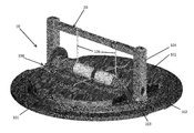
With reference to FIGS. 5-7, a check valve 10 is illustrated in closed, partially open and fully open conditions, respectively. As shown, the check valve 10 may include a check valve body 100 and disks 101. The check valve body 100 includes a seat 102, a hinge 103 and a housing 104. The seat 102 may be annularly shaped and formed to define an aperture 105 (see FIG. 7). The hinge 103 may be provided as a pin-hinge with a central pivot axis defined along a pin and may be disposed to bifurcate the aperture 105 defined by the seat 102 to thereby further define openings on either side of the hinge 103. The housing 104 is coupled to opposite ends of the hinge 103 and normally includes the mechanical stop 20 as described above.
The disks 101 are pivotably coupled to the hinge 103 to pivot or swing about the central pivot axis in response to a fluid pressure differential between fluid disposed upstream and fluid disposed downstream from the check valve 10. In particular, the disks 101 are biased by elastic elements 106 to remain in respective closed positions (see FIG. 5) at which the disks 101 prevent fluid flow through the openings. However, when the fluid pressure differential is sufficiently large to overcome the bias applied by the elastic elements 106, the disks 101 begin to open (see FIG. 6) and eventually swing into respective open positions (see FIG. 7) whereby fluid flow through the openings is permitted. When the disks 101 swing toward the respective open positions, they independently impact the mechanical stop 20 and are thereby prevented from swinging beyond a given opening angle.
While the invention has been described in detail in connection with only a limited number of embodiments, it should be readily understood that the invention is not limited to such disclosed embodiments. Rather, the invention can be modified to incorporate any number of variations, alterations, substitutions or equivalent arrangements not heretofore described, but which are commensurate with the spirit and scope of the invention. Additionally, while various embodiments of the invention have been described, it is to be understood that aspects of the invention may include only some of the described embodiments. Accordingly, the invention is not to be seen as limited by the foregoing description, but is only limited by the scope of the appended claims.

Claims (20)

The invention claimed is:
1. A dual disk check valve, comprising:
a mechanical stop, the mechanical stop having a central portion and including:
bars disposed in the central portion, the bars having substantially straight and rectangular cross-sectional shapes along respective entireties of respective lengths of each of the bars and being disposed substantially in parallel with one another to define a slot in the central portion along the respective entireties of the respective lengths of each of the bars.
2. The check valve according to claim 1, further comprising distal sections are configured as anti-rotation features.
3. The check valve according to claim 1, further comprising intermediate sections to which respective opposite ends of the bars are coupled, the intermediate sections having substantially rectangular cross-sectional shapes.
4. The check valve according to claim 3, wherein the intermediate sections are each formed to define grounding holes for tension springs and each have opposite faces that are configured to impact check valve disks swinging open.
5. The check valve according to claim 3, wherein each of the respective opposite ends of the bars comprises flared end.
6. The check valve according to claim 1, wherein a relative shape and size of each of the bars is independently tunable.
7. The check valve according to claim 1, wherein a shortest dimension of each of the bars is transversely oriented with respect to an elongation dimension of the elongate member.
8. A dual disk check valve, comprising:
a mechanical stop, the mechanical stop having a central portion and including:
bars disposed in the central portion, the bars having substantially rectangular cross-sectional shapes and being disposed substantially in parallel with one another to define a slot in the central portion,
wherein the slot is filled with a non-elastic energy absorbing material.
9. A mechanical stop of a dual disk check valve, comprising:
an elongate member having distal sections at opposite ends thereof, intermediate sections coupled to the distal sections and a central portion between the intermediate sections; and
bars respectively including opposite ends, the opposite ends of each of the bars being respectively coupled to the intermediate sections,
the bars having substantially straight and rectangular cross-sectional shapes along respective entireties of respective lengths of each of the bars and being disposed substantially in parallel with one another to define a slot in the central portion along the respective entireties of the respective lengths of each of the bars.
10. The mechanical stop according to claim 9, wherein the distal sections are configured as anti-rotation features.
11. The mechanical stop according to claim 9, wherein the intermediate sections have substantially rectangular cross-sectional shapes.
12. The mechanical stop according to claim 9, wherein the intermediate sections are formed to define grounding holes for tension springs.
13. The mechanical stop according to claim 12, wherein the grounding holes are proximate to the central section.
14. The mechanical stop according to claim 9, wherein the intermediate sections each have opposite faces that are configured to impact check valve disks swinging open.
15. The mechanical stop according to claim 14, wherein a contact area between the opposite faces and the disks is non-linear.
16. The mechanical stop according to claim 9, wherein each of the respective opposite ends of each of the bars comprises flared end.
17. The mechanical stop according to claim 9, wherein a relative shape and size of each of the bars is independently tunable.
18. The mechanical stop according to claim 9, wherein a shortest dimension of each of the bars is transversely oriented with respect to an elongation dimension of the elongate member.
19. A mechanical stop of a dual disk check valve, comprising:
an elongate member having distal sections at opposite ends thereof, intermediate sections coupled to the distal sections and a central portion between the intermediate sections; and
bars respectively coupled to the intermediate sections,
the bars having substantially rectangular cross-sectional shapes and being disposed substantially in parallel with one another to define a slot in the central portion,
wherein the slot is filled with a non-elastic energy absorbing material.
20. A mechanical stop of a dual disk check valve, comprising:
an elongate member having distal sections formed as anti-rotation features at opposite ends thereof, substantially rectangular intermediate sections coupled to the distal sections and a central portion between the intermediate sections; and
bars respectively including opposite ends, the opposite ends of each of the bars being respectively coupled to respective interior portions of the intermediate sections for disposition thereof in the central portion,
the bars having substantially straight and rectangular cross-sectional shapes along respective entireties of respective lengths of each of the bars and being disposed substantially in parallel with one another to define a slot in the central portion along the respective entireties of the respective lengths of each of the bars.
US13/570,926 2012-08-09 2012-08-09 Dual disk check valve with slotted stop bar Active US8726930B2 (en)

Priority Applications (2)

Application Number Priority Date Filing Date Title
US13/570,926 US8726930B2 (en) 2012-08-09 2012-08-09 Dual disk check valve with slotted stop bar
FR1356609A FR2994469B1 (en) 2012-08-09 2013-07-05 DOUBLE-DISCHARGE CHECK VALVE WITH GROOVE BAR

Applications Claiming Priority (1)

Application Number Priority Date Filing Date Title
US13/570,926 US8726930B2 (en) 2012-08-09 2012-08-09 Dual disk check valve with slotted stop bar

Publications (2)

Publication Number Publication Date
US20140041739A1 US20140041739A1 (en) 2014-02-13
US8726930B2 true US8726930B2 (en) 2014-05-20

Family

ID=50002926

Family Applications (1)

Application Number Title Priority Date Filing Date
US13/570,926 Active US8726930B2 (en) 2012-08-09 2012-08-09 Dual disk check valve with slotted stop bar

Country Status (2)

Country Link
US (1) US8726930B2 (en)
FR (1) FR2994469B1 (en)

Cited By (6)

* Cited by examiner, † Cited by third party
Publication number Priority date Publication date Assignee Title
US20150068612A1 (en) * 2013-09-09 2015-03-12 Hamilton Sundstrand Corporation Valve with precision mounted hinge pin posts
US20160040794A1 (en) * 2014-07-31 2016-02-11 HS Wroclaw Sp. z o. o. Check valves
US20160201577A1 (en) * 2015-01-09 2016-07-14 Wen-Chuan Chen Gas flow adjusting device
US10167974B2 (en) 2016-01-14 2019-01-01 Hamilton Sundstrand Check valves
US10539244B2 (en) 2016-06-14 2020-01-21 Hamilton Sundstrand Corporation Check valve
US10539245B2 (en) 2016-07-19 2020-01-21 Hamilton Sundstrand Corporation Check valve

Families Citing this family (5)

* Cited by examiner, † Cited by third party
Publication number Priority date Publication date Assignee Title
US9383023B2 (en) 2014-02-27 2016-07-05 Hamilton Sundstrand Corporation High opening velocity check valve
EP3181964B1 (en) * 2015-12-14 2018-08-22 Hamilton Sundstrand Corporation Check valve
EP3181969B1 (en) * 2015-12-14 2019-08-07 Hamilton Sundstrand Corporation Check valve
EP3508765B1 (en) 2018-01-09 2021-03-03 Hamilton Sundstrand Corporation Check valves
EP4083478A1 (en) * 2021-04-27 2022-11-02 UTC Aerospace Systems Wroclaw Sp. z o.o. Flapper check valve

Citations (15)

* Cited by examiner, † Cited by third party
Publication number Priority date Publication date Assignee Title
US2358101A (en) * 1943-03-23 1944-09-12 Merwyn C Randall Relief valve
US4373544A (en) 1980-09-25 1983-02-15 United Technologies Corporation Check valve
US5784894A (en) 1996-12-18 1998-07-28 United Technologies Corporation Integral bypass valves and air cycle machine
US5836349A (en) 1996-12-30 1998-11-17 Carrier Corporation Bidirectional flow control device
US5924445A (en) 1997-02-20 1999-07-20 Sikorsky Aircraft Corporation Fuel intake device for fuel systems
US6851255B2 (en) 2002-12-18 2005-02-08 Pratt & Whitney Canada Corp. Normally open reverse flow flapper valve
US20080053536A1 (en) 2006-08-31 2008-03-06 Honeywell International, Inc. High flow insert type check valve
US20080072973A1 (en) 2006-09-25 2008-03-27 Honeywell International, Inc. Rotary pneumatic damper for check valve
US20080078459A1 (en) 2006-09-29 2008-04-03 Honeywell International, Inc. Rotary hydraulic damper for check valve
US20080078458A1 (en) 2006-09-29 2008-04-03 Honeywell International, Inc. Linear damper for check valve
US7493770B2 (en) 2004-08-09 2009-02-24 General Electric Company Methods and apparatus for regulating airflow supply systems
US20090071549A1 (en) 2006-08-30 2009-03-19 Honeywell International, Inc. Flapper with insert stops for check valve
US7568498B2 (en) 2006-09-26 2009-08-04 Honeywell International Inc. Engineered composite quiet check valve
EP2249068A2 (en) 2009-05-06 2010-11-10 Hamilton Sundstrand Corporation Compliant check valve stop
US8201576B2 (en) 2006-04-05 2012-06-19 Klein Gerald A Reinforced elastomeric hinge check valve

Family Cites Families (1)

* Cited by examiner, † Cited by third party
Publication number Priority date Publication date Assignee Title
US4867199A (en) * 1988-12-14 1989-09-19 Imo Industries, Inc. Bi-petal l check-valve construction

Patent Citations (20)

* Cited by examiner, † Cited by third party
Publication number Priority date Publication date Assignee Title
US2358101A (en) * 1943-03-23 1944-09-12 Merwyn C Randall Relief valve
US4373544A (en) 1980-09-25 1983-02-15 United Technologies Corporation Check valve
US5784894A (en) 1996-12-18 1998-07-28 United Technologies Corporation Integral bypass valves and air cycle machine
US5836349A (en) 1996-12-30 1998-11-17 Carrier Corporation Bidirectional flow control device
US5924445A (en) 1997-02-20 1999-07-20 Sikorsky Aircraft Corporation Fuel intake device for fuel systems
US6851255B2 (en) 2002-12-18 2005-02-08 Pratt & Whitney Canada Corp. Normally open reverse flow flapper valve
US7114519B2 (en) 2002-12-18 2006-10-03 Pratt & Whitney Canada Corp. Normally open reverse flow flapper valve
US7493770B2 (en) 2004-08-09 2009-02-24 General Electric Company Methods and apparatus for regulating airflow supply systems
US8201576B2 (en) 2006-04-05 2012-06-19 Klein Gerald A Reinforced elastomeric hinge check valve
US7779859B2 (en) 2006-08-30 2010-08-24 Honeywell International Inc. Flapper with insert stops for check valve
US20090071549A1 (en) 2006-08-30 2009-03-19 Honeywell International, Inc. Flapper with insert stops for check valve
US20080053536A1 (en) 2006-08-31 2008-03-06 Honeywell International, Inc. High flow insert type check valve
US20080072973A1 (en) 2006-09-25 2008-03-27 Honeywell International, Inc. Rotary pneumatic damper for check valve
US7568498B2 (en) 2006-09-26 2009-08-04 Honeywell International Inc. Engineered composite quiet check valve
US20080078458A1 (en) 2006-09-29 2008-04-03 Honeywell International, Inc. Linear damper for check valve
US7422029B2 (en) 2006-09-29 2008-09-09 Honeywell International Inc. Linear damper for check valve
US20080078459A1 (en) 2006-09-29 2008-04-03 Honeywell International, Inc. Rotary hydraulic damper for check valve
EP2249068A2 (en) 2009-05-06 2010-11-10 Hamilton Sundstrand Corporation Compliant check valve stop
US20100282340A1 (en) 2009-05-06 2010-11-11 Hamilton Sundstrand Corporation Compliant check valve stop
US8181669B2 (en) 2009-05-06 2012-05-22 Hamilton Sundstrand Corporation Compliant check valve stop

Cited By (9)

* Cited by examiner, † Cited by third party
Publication number Priority date Publication date Assignee Title
US20150068612A1 (en) * 2013-09-09 2015-03-12 Hamilton Sundstrand Corporation Valve with precision mounted hinge pin posts
US9279509B2 (en) * 2013-09-09 2016-03-08 Hamilton Sundstrand Corporation Valve with precision mounted hinge pin posts
US20160040794A1 (en) * 2014-07-31 2016-02-11 HS Wroclaw Sp. z o. o. Check valves
US9890864B2 (en) * 2014-07-31 2018-02-13 Hamilton Sundstrand Corporation Check valves
US20160201577A1 (en) * 2015-01-09 2016-07-14 Wen-Chuan Chen Gas flow adjusting device
US9664119B2 (en) * 2015-01-09 2017-05-30 Wen-Chuan Chen Gas flow adjusting device
US10167974B2 (en) 2016-01-14 2019-01-01 Hamilton Sundstrand Check valves
US10539244B2 (en) 2016-06-14 2020-01-21 Hamilton Sundstrand Corporation Check valve
US10539245B2 (en) 2016-07-19 2020-01-21 Hamilton Sundstrand Corporation Check valve

Also Published As

Publication number Publication date
US20140041739A1 (en) 2014-02-13
FR2994469B1 (en) 2016-09-02
FR2994469A1 (en) 2014-02-14

Similar Documents

Publication Publication Date Title
US8726930B2 (en) Dual disk check valve with slotted stop bar
US9835261B2 (en) Check valves
US9581256B2 (en) Valve flapper spring stop mechanism
US9890864B2 (en) Check valves
US10539244B2 (en) Check valve
EP2072871A2 (en) Check valve
US10794503B2 (en) Method for locating check valve pin
US10309551B2 (en) Check valves
CN101994861A (en) Check valve apparatuses and methods
EP3232101B1 (en) Flapper check valve bumper
US8714190B2 (en) Metal plate for dual plate check valve
US10533671B2 (en) Check valve
CA2819735C (en) Dual disk check valve with slotted stop bar
US10167974B2 (en) Check valves
US9206913B2 (en) Check valve having petals with lift generating elements
US10539245B2 (en) Check valve
AU2017330468B2 (en) Contoured check valve disc for low cracking pressure
US10648581B2 (en) Check valves

Legal Events

Date Code Title Description
AS Assignment

Owner name: HAMILTON SUNDSTRAND CORPORATION, CONNECTICUT

Free format text: ASSIGNMENT OF ASSIGNORS INTEREST;ASSIGNOR:BARONE, MICHAEL;REEL/FRAME:028759/0856

Effective date: 20120808

STCF Information on status: patent grant

Free format text: PATENTED CASE

MAFP Maintenance fee payment

Free format text: PAYMENT OF MAINTENANCE FEE, 4TH YEAR, LARGE ENTITY (ORIGINAL EVENT CODE: M1551)

Year of fee payment: 4

MAFP Maintenance fee payment

Free format text: PAYMENT OF MAINTENANCE FEE, 8TH YEAR, LARGE ENTITY (ORIGINAL EVENT CODE: M1552); ENTITY STATUS OF PATENT OWNER: LARGE ENTITY

Year of fee payment: 8