EP3181960B1 - Balanced valve element and pressure regulating valve - Google Patents
Balanced valve element and pressure regulating valve Download PDFInfo
- Publication number
- EP3181960B1 EP3181960B1 EP15825096.9A EP15825096A EP3181960B1 EP 3181960 B1 EP3181960 B1 EP 3181960B1 EP 15825096 A EP15825096 A EP 15825096A EP 3181960 B1 EP3181960 B1 EP 3181960B1
- Authority
- EP
- European Patent Office
- Prior art keywords
- valve
- pressure regulating
- diaphragm
- valve rod
- rod
- Prior art date
- Legal status (The legal status is an assumption and is not a legal conclusion. Google has not performed a legal analysis and makes no representation as to the accuracy of the status listed.)
- Active
Links
Images


Classifications
-
- F—MECHANICAL ENGINEERING; LIGHTING; HEATING; WEAPONS; BLASTING
- F16—ENGINEERING ELEMENTS AND UNITS; GENERAL MEASURES FOR PRODUCING AND MAINTAINING EFFECTIVE FUNCTIONING OF MACHINES OR INSTALLATIONS; THERMAL INSULATION IN GENERAL
- F16K—VALVES; TAPS; COCKS; ACTUATING-FLOATS; DEVICES FOR VENTING OR AERATING
- F16K31/00—Actuating devices; Operating means; Releasing devices
- F16K31/12—Actuating devices; Operating means; Releasing devices actuated by fluid
- F16K31/126—Actuating devices; Operating means; Releasing devices actuated by fluid the fluid acting on a diaphragm, bellows, or the like
- F16K31/1262—Actuating devices; Operating means; Releasing devices actuated by fluid the fluid acting on a diaphragm, bellows, or the like one side of the diaphragm being spring loaded
-
- F—MECHANICAL ENGINEERING; LIGHTING; HEATING; WEAPONS; BLASTING
- F16—ENGINEERING ELEMENTS AND UNITS; GENERAL MEASURES FOR PRODUCING AND MAINTAINING EFFECTIVE FUNCTIONING OF MACHINES OR INSTALLATIONS; THERMAL INSULATION IN GENERAL
- F16K—VALVES; TAPS; COCKS; ACTUATING-FLOATS; DEVICES FOR VENTING OR AERATING
- F16K1/00—Lift valves or globe valves, i.e. cut-off apparatus with closure members having at least a component of their opening and closing motion perpendicular to the closing faces
- F16K1/12—Lift valves or globe valves, i.e. cut-off apparatus with closure members having at least a component of their opening and closing motion perpendicular to the closing faces with streamlined valve member around which the fluid flows when the valve is opened
- F16K1/126—Lift valves or globe valves, i.e. cut-off apparatus with closure members having at least a component of their opening and closing motion perpendicular to the closing faces with streamlined valve member around which the fluid flows when the valve is opened actuated by fluid
-
- F—MECHANICAL ENGINEERING; LIGHTING; HEATING; WEAPONS; BLASTING
- F16—ENGINEERING ELEMENTS AND UNITS; GENERAL MEASURES FOR PRODUCING AND MAINTAINING EFFECTIVE FUNCTIONING OF MACHINES OR INSTALLATIONS; THERMAL INSULATION IN GENERAL
- F16K—VALVES; TAPS; COCKS; ACTUATING-FLOATS; DEVICES FOR VENTING OR AERATING
- F16K1/00—Lift valves or globe valves, i.e. cut-off apparatus with closure members having at least a component of their opening and closing motion perpendicular to the closing faces
- F16K1/32—Details
- F16K1/34—Cutting-off parts, e.g. valve members, seats
- F16K1/36—Valve members
-
- F—MECHANICAL ENGINEERING; LIGHTING; HEATING; WEAPONS; BLASTING
- F16—ENGINEERING ELEMENTS AND UNITS; GENERAL MEASURES FOR PRODUCING AND MAINTAINING EFFECTIVE FUNCTIONING OF MACHINES OR INSTALLATIONS; THERMAL INSULATION IN GENERAL
- F16K—VALVES; TAPS; COCKS; ACTUATING-FLOATS; DEVICES FOR VENTING OR AERATING
- F16K39/00—Devices for relieving the pressure on the sealing faces
- F16K39/02—Devices for relieving the pressure on the sealing faces for lift valves
- F16K39/022—Devices for relieving the pressure on the sealing faces for lift valves using balancing surfaces
-
- G—PHYSICS
- G05—CONTROLLING; REGULATING
- G05D—SYSTEMS FOR CONTROLLING OR REGULATING NON-ELECTRIC VARIABLES
- G05D16/00—Control of fluid pressure
- G05D16/02—Modifications to reduce the effects of instability, e.g. due to vibrations, friction, abnormal temperature, overloading or imbalance
-
- G—PHYSICS
- G05—CONTROLLING; REGULATING
- G05D—SYSTEMS FOR CONTROLLING OR REGULATING NON-ELECTRIC VARIABLES
- G05D16/00—Control of fluid pressure
- G05D16/04—Control of fluid pressure without auxiliary power
- G05D16/06—Control of fluid pressure without auxiliary power the sensing element being a flexible membrane, yielding to pressure, e.g. diaphragm, bellows, capsule
- G05D16/063—Control of fluid pressure without auxiliary power the sensing element being a flexible membrane, yielding to pressure, e.g. diaphragm, bellows, capsule the sensing element being a membrane
- G05D16/0636—Control of fluid pressure without auxiliary power the sensing element being a flexible membrane, yielding to pressure, e.g. diaphragm, bellows, capsule the sensing element being a membrane characterised by the loading device of the membrane, e.g. spring
-
- G—PHYSICS
- G05—CONTROLLING; REGULATING
- G05D—SYSTEMS FOR CONTROLLING OR REGULATING NON-ELECTRIC VARIABLES
- G05D16/00—Control of fluid pressure
- G05D16/04—Control of fluid pressure without auxiliary power
- G05D16/06—Control of fluid pressure without auxiliary power the sensing element being a flexible membrane, yielding to pressure, e.g. diaphragm, bellows, capsule
- G05D16/063—Control of fluid pressure without auxiliary power the sensing element being a flexible membrane, yielding to pressure, e.g. diaphragm, bellows, capsule the sensing element being a membrane
- G05D16/0644—Control of fluid pressure without auxiliary power the sensing element being a flexible membrane, yielding to pressure, e.g. diaphragm, bellows, capsule the sensing element being a membrane the membrane acting directly on the obturator
- G05D16/0655—Control of fluid pressure without auxiliary power the sensing element being a flexible membrane, yielding to pressure, e.g. diaphragm, bellows, capsule the sensing element being a membrane the membrane acting directly on the obturator using one spring-loaded membrane
Definitions
- the present invention belongs to the field of fluid control, in particular relates to a balanced valve element and further relates to a pressure regulating valve comprising the balanced valve element.
- Known pressure regulating valves are described for example in the documents FR 1331025 A and GB 286249 A .
- a known fluid control valve and a known fuel cell system are also described in the document US 2010/035117 A1 .
- FIG. 1 involves a design method of an existing balanced valve element.
- this design method one end of an n-shaped diaphragm is fixedly connected to a valve rod and the other end of the n-shaped diaphragm is fixedly connected to a valve body or a connecting member (which connects the valve body and an actuator), wherein a fixing member needs to be used at the end of the n-shaped diaphragm which is connected to the valve rod, to fix the n-shaped diaphragm on the valve rod.
- FIG. 2 involves another design method of an existing balanced valve element.
- This design method adopts a valve rod moving piston structure, and an O-ring 20 is arranged on a piston sleeve to achieve a sealing effect of isolating inlet pressure from outlet pressure.
- this structure does not facilitate guiding (since the O-ring has elasticity, the valve rod will swing).
- a guide sleeve 30 needs to be additionally arranged.
- an additional space needs to be added in a longitudinal space of a valve, resulting that the structure of the valve is comparatively complex.
- the present invention provides a balanced valve element and a pressure regulating valve comprising the balanced valve element.
- an embodiment of the present invention discloses a balanced valve element, comprising:
- the above-described piston sleeve comprises a sleeve body and a bottom, the bottom of the piston sleeve is fixed on the valve rod and a first gap is arranged between an inner wall of the sleeve body of the piston sleeve and an outer wall of the valve rod.
- a first sealing part is arranged between the above-described fixing member and the sleeve body of the piston sleeve.
- an embodiment of the present invention discloses a pressure regulating valve, comprising:
- the above-described fixing member is fixedly connected onto the actuator.
- the above-described actuator comprises:
- the above-described fixing member is fixed on the second diaphragm cap; or the above-described fixing member and the second diaphragm cap are integrally molded.
- the above-described pressure regulating valve further comprises a guide sleeve which is fixed on the second diaphragm cap, and the guide sleeve is a ring which surrounds a cross section of the valve rod.
- the above-described pressure regulating valve further comprises a guide sleeve which is located on an outer circumference of the valve rod.
- the number of the above-described guide sleeves is at least two.
- the bottom of the above-described piston sleeve comprises an extension portion which outwardly extends along the axis direction of the valve rod, and the extension portion is closely fixed on the valve rod.
- valve rod and the piston sleeve are integrally molded.
- a second sealing part is arranged at a junction between the above-described valve rod and the bottom of the piston sleeve.
- a balanced valve element disclosed by this embodiment is located in a pressure regulating valve.
- the pressure regulating valve comprises a valve body, a balanced valve element and an actuator.
- the valve body 2 comprises an inlet 21, an outlet 22 and a valve cavity 23.
- the actuator is fixedly connected to the valve body.
- inlet pressure may be gas pressure and may also be liquid pressure
- outlet pressure may be gas pressure and may also be liquid pressure.
- the balanced valve element comprises a valve rod 11, a piston sleeve 12, a valve seat 13 and a fixing member 14.
- the valve rod 11 comprises a first end 111 and a second end 112, wherein the first end 111 of the valve rod is arranged in the actuator of the valve and the second end 112 of the valve rod is fixed within the valve seat 13.
- the valve seat 13 is movably arranged in the valve cavity 23.
- the piston sleeve 12 comprises a sleeve body 121 and a bottom 122, wherein the bottom 122 of the piston sleeve is fixed on the valve rod 11, and a first gap A is arranged between an inner wall of the sleeve body of the piston sleeve and an outer wall of the valve rod.
- the fixing member 14 is fixed on the actuator of the valve, and the fixing member 14 is arranged between the valve rod 11 and the piston sleeve 12 along the axis direction of the valve rod.
- the valve rod 11, the piston sleeve 12 and the valve seat 13 can move along the axis direction of the valve rod.
- the fixing member 14 here achieves an effect of guiding the valve rod 11 and simultaneously achieves a sealing effect of isolating the inlet pressure from the outlet pressure.
- a first sealing part 15 may be arranged between the fixing member 14 and the sleeve body 121 of the piston sleeve 12.
- the first sealing part 15 may be an O-ring and may also be a sealing packing and the like. It needs to be stated that sealing described here is dynamic sealing since the fixing member 14 and the piston sleeve 12 are relatively movable.
- the inlet pressure is isolated from the outlet pressure since the purpose of the pressure regulating valve is to keep a stable outlet pressure. The inlet pressure is certainly higher than the outlet pressure, if no isolation measure is taken, the outlet pressure will always rise.
- a second gap B is arranged between the fixing member 14 and the bottom 122 of the piston sleeve
- a third gap C is arranged between the actuator of the pressure regulating valve and the piston sleeve
- a fourth gap D is arranged between the valve body and the piston sleeve.
- the valve cavity 23 comprises a first region 231 in communication with the inlet 21, a second region 232 in communication with the outlet 22, and a valve port 233 communicating the first region 231 with the second region 232.
- the valve seat 13 moves between the valve port 233 and the second region 232.
- the actuator comprises a diaphragm cap assembly, a diaphragm assembly and a pressure regulating means, wherein the diaphragm cap assembly comprises a first diaphragm cap 311 and a second diaphragm cap 312, the first diaphragm cap 311 is connected to the pressure regulating means, the second diaphragm cap 312 is connected to the valve body 2, and the first diaphragm cap 311 mates with the second diaphragm cap 312 to form a hollow internal portion.
- the diaphragm assembly comprises a diaphragm 321, a first diaphragm plate 322 and a second diaphragm plate 323, wherein the diaphragm 321 is pressed between the first diaphragm plate 322 and the second diaphragm plate 323, the diaphragm 321 is located between the first diaphragm cap 311 and the second diaphragm cap 312, the first diaphragm plate 322 is located within a cavity formed by the diaphragm 321 and the first diaphragm cap 311, and the second diaphragm plate 323 is located within a cavity formed by the diaphragm 321 and the second diaphragm cap 312.
- the pressure regulating means comprises a spring 331 and a regulating rod 332, wherein the spring 331 is located inside the first diaphragm cap 311, the regulating rod 332 comprises a third end 3321 and a fourth end 3322, the third end 3321 of the regulating rod penetrates through the first diaphragm cap 311 and is in contact with the spring 331, the fourth end 3322 of the regulating rod is suspended in the air, and the regulating rod is fixed on the first diaphragm cap 311.
- the first diaphragm plate 322 further achieves an effect of supporting the spring 331 and transmitting spring force.
- the second diaphragm plate 323 further achieves an effect of isolating the outlet pressure from outside.
- the first end 111 of the valve rod penetrates through the diaphragm 321 and is fixed on the first diaphragm plate 322.
- the fixing member 14 is fixed on the second diaphragm cap 312.
- the fixing member 14 may be integrally molded with the second diaphragm cap 312 , and may also be fixed on the second diaphragm cap 312 as an independent part.
- the fixing member 14 and the second diaphragm cap 312 are integrally molded. It needs to be stated that the fixing member 14 is not limited to be fixed on the second diaphragm cap 312 and may be fixed with the actuator or the valve body as long as the scope of the present invention as defined by the appended claims is satisfied.
- the pressure regulating valve provided by the embodiment further comprises a guide sleeve 17, the guide sleeve 17 is fixed on the second diaphragm cap 312 and the guide sleeve 17 is a ring which surrounds the cross section of the valve rod.
- the number of the guide rings is two. Of course, the number of the guide rings may also be one or more. If a guide surface in contact with the valve rod 11 is sufficiently smooth, there may be no guide ring.
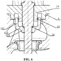
- FIG. 6 illustrates a balanced valve element which has no guide sleeve.
- the guide sleeve 17 may be made of materials such as bronze or PTFE, etc. The guide sleeve 17 achieves an effect of guiding the valve rod 11 and further achieves an effect of reducing friction.
- the guide sleeve 17 may also be located on an outer circumference of the valve rod 11 (instead of the second diaphragm cap of the actuator) and is approximately located on the outer circumference of a middle portion of the valve rod, wherein the middle portion of the valve rod refers to a portion between the first end 111 of the valve rod and the piston sleeve 12.
- valve rod 11 and the piston sleeve 12 may be two independent parts and may also be integrally molded. If they are two independent parts, in order to isolate the inlet pressure from the outlet pressure, a second sealing part 16 is arranged at a junction between the valve rod 11 and the bottom 122 of the piston sleeve, so as to achieve a sealing effect.
- the second sealing part 16 may be an O-ring and may also be a sealing packing and the like. It needs to be stated that sealing here is static sealing since the fixing member 14 and the piston sleeve 12 are relatively stationary.
- the inlet pressure is isolated form the outlet pressure since the purpose of the pressure regulating valve is to keep a stable outlet pressure. The inlet pressure is certainly higher than the outlet pressure, if no isolation measure is taken, the outlet pressure will always rise.
- the piston sleeve may also adopt other structures as long as the scope of the present invention is satisfied, and is not limited to the structures of the piston sleeve illustrated in FIG. 3 and FIG. 4 .
- the bottom 122 of the piston sleeve may further comprise an extension portion 123 which outwardly extends along the axis direction of the valve rod. The extension portion 123 is closely fixed on the valve rod 11, as illustrated in FIG. 5 and FIG. 6 .
- the second diaphragm cap 312 of the actuator and the valve body 2 are fixedly connected through a screw as illustrated in FIG. 4 , and may also be fixedly connected by other means. If a contact portion between the second diaphragm cap 312 and the valve body 2 is not well sealed, a third sealing part 4 may be arranged at this contact portion to isolate a medium within the valve body from an external environment, so as to achieve a sealing effect.
- the third sealing part may be an O-ring and may also be a sealing packing and the like.
- the design of the above-mentioned embodiment simplifies the structure of the existing pressure regulating valve (mainly the balanced valve element portion), the number of parts is reduced, thereby the cost is decreased and simultaneously an additional space does not need to be added in a longitudinal direction for the guide sleeve of the valve rod.
- the working principle of the above-mentioned pressure regulating valve is as follow: gas or liquid enters the valve from the inlet along the first region, inlet pressure acts on the valve seat to produce downward pressure and the effect of the balanced valve element is to produce an upward force to balance the downward pressure, wherein the bottom of the piston sleeve achieves the effect of bearing the upward pressure.
- a user sets the magnitude of the desired outlet pressure by regulating the magnitude of spring force through the regulating rod. Under the effect of the spring force, the valve rod is enabled to move up and down, and at this moment the valve seat moves up and down between the second region and the valve port.
- the magnitude of the force produced by the inlet pressure to the valve seat may be changed by changing a contact area between the bottom of the piston sleeve and the inlet gas pressure (or inlet liquid pressure), so as to satisfy the actual need.
- the size of the diaphragm may be adjusted to find the most suitable diaphragm size to output the magnitude of the desired outlet pressure.
Landscapes
- Engineering & Computer Science (AREA)
- Physics & Mathematics (AREA)
- General Engineering & Computer Science (AREA)
- Fluid Mechanics (AREA)
- Mechanical Engineering (AREA)
- General Physics & Mathematics (AREA)
- Automation & Control Theory (AREA)
- Control Of Fluid Pressure (AREA)
Description
- The present invention belongs to the field of fluid control, in particular relates to a balanced valve element and further relates to a pressure regulating valve comprising the balanced valve element.
- In pressure regulator design, since inlet pressure acts on a valve seat to produce an additional force, this force directly influence the performance of a pressure regulator product. Therefore, usually a structure of a balanced valve element is designed.
- Known pressure regulating valves are described for example in the documents
FR 1331025 A GB 286249 A US 2010/035117 A1 . -
FIG. 1 involves a design method of an existing balanced valve element. In this design method, one end of an n-shaped diaphragm is fixedly connected to a valve rod and the other end of the n-shaped diaphragm is fixedly connected to a valve body or a connecting member (which connects the valve body and an actuator), wherein a fixing member needs to be used at the end of the n-shaped diaphragm which is connected to the valve rod, to fix the n-shaped diaphragm on the valve rod. FromFIG. 1 , it can be seen that the structure of this balanced valve element is complex, the number of parts is great and the cost is relatively higher. -
FIG. 2 involves another design method of an existing balanced valve element. This design method adopts a valve rod moving piston structure, and an O-ring 20 is arranged on a piston sleeve to achieve a sealing effect of isolating inlet pressure from outlet pressure. However, this structure does not facilitate guiding (since the O-ring has elasticity, the valve rod will swing). Moreover, it is difficult to guarantee the finish of a cylindrical surface of the piston sleeve in contact with the O-ring . In order to realize guiding, aguide sleeve 30 needs to be additionally arranged. However, in order to install the guide sleeve, an additional space needs to be added in a longitudinal space of a valve, resulting that the structure of the valve is comparatively complex. - In order to solve the problem that the structure of the existing balanced valve element is complex, the present invention provides a balanced valve element and a pressure regulating valve comprising the balanced valve element.
- In one aspect, an embodiment of the present invention discloses a balanced valve element, comprising:
- a valve rod;
- a piston sleeve fixed on the valve rod; and
- a fixing member sleeved between the valve rod and the piston sleeve, the fixing member being arranged in a direction in parallel with an axis of the valve rod.
- The above-described piston sleeve comprises a sleeve body and a bottom, the bottom of the piston sleeve is fixed on the valve rod and a first gap is arranged between an inner wall of the sleeve body of the piston sleeve and an outer wall of the valve rod.
- A first sealing part is arranged between the above-described fixing member and the sleeve body of the piston sleeve.
- In another aspect, an embodiment of the present invention discloses a pressure regulating valve, comprising:
- a valve body provided with a valve cavity;
- an actuator fixedly connected to the valve body; and
- the above-described balanced valve element.
- The above-described fixing member is fixedly connected onto the actuator.
- The above-described actuator comprises:
- a pressure regulating means;
- a diaphragm cap assembly comprising a first diaphragm cap and a second diaphragm cap, the first diaphragm cap being connected to the pressure regulating means, the second diaphragm cap being connected to the valve body, and the first diaphragm cap mating with the second diaphragm cap to form a hollow internal portion; and
- a diaphragm assembly comprising a diaphragm, the diaphragm being located between the first diaphragm cap and the second diaphragm cap.
- The above-described fixing member is fixed on the second diaphragm cap; or the above-described fixing member and the second diaphragm cap are integrally molded.
- The above-described pressure regulating valve further comprises a guide sleeve which is fixed on the second diaphragm cap, and the guide sleeve is a ring which surrounds a cross section of the valve rod.
- Alternatively, the above-described pressure regulating valve further comprises a guide sleeve which is located on an outer circumference of the valve rod.
- The number of the above-described guide sleeves is at least two.
- The bottom of the above-described piston sleeve comprises an extension portion which outwardly extends along the axis direction of the valve rod, and the extension portion is closely fixed on the valve rod.
- The above-described valve rod and the piston sleeve are integrally molded.
- A second sealing part is arranged at a junction between the above-described valve rod and the bottom of the piston sleeve.
- According to the embodiments of the present invention, by connecting the fixing member onto the actuator of the valve and arranging the fixing member between the valve rod and the piston sleeve in the axis direction of the valve rod, an effect of guiding the valve rod is achieved and simultaneously a sealing effect of isolating inlet pressure from outlet pressure is achieved. This design has a simpler structure than the related art.
-
-
FIG. 1 illustrates a structural schematic view of a balanced valve element in related art 1; -
FIG. 2 illustrates a structural schematic view of a balanced valve element in related art 2; -
FIG. 3 illustrates a structural schematic view of a balanced valve element provided by embodiment 1 of the present invention; -
FIG. 4 illustrates a structural schematic view of a pressure regulating valve provided by embodiment 1 of the present invention; -
FIG. 5 illustrates a structural schematic view of a balanced valve element provided by embodiment 2 of the present invention; -
FIG. 6 illustrates a structural schematic view of a balanced valve element provided by embodiment 3 of the present invention. - Description of reference signs: 11-valve rod, 111-first end, 112-second end, 12-piston sleeve, 121-sleeve body, 122-bottom, 123-extension portion, 13-valve seat, 14-fixing member, A-first gap, B-second gap, C-third gap, D-third gap, 15-first sealing part, 16-second sealing part, 17-guide sleeve, 2-valve body, 21-inlet, 22-outlet, 23-valve cavity, 231-first region, 232-second region, 233-valve port, 311-first diaphragm cap, 312-second diaphragm cap, 321-diaphragm, 322-first diaphragm plate, 323-second diaphragm plate, 331-spring, 332-regulating rod, 3321-third end, 3322-fourth end, 4-third sealing part.
- The technical solution of the present invention will be further described below with reference to the drawings in combination with the specific embodiments.
- A balanced valve element disclosed by this embodiment is located in a pressure regulating valve. As illustrated in
FIG. 4 , the pressure regulating valve comprises a valve body, a balanced valve element and an actuator. The valve body 2 comprises aninlet 21, anoutlet 22 and avalve cavity 23. The actuator is fixedly connected to the valve body. For the pressure regulating valve provided by this disclosure, inlet pressure may be gas pressure and may also be liquid pressure, and correspondingly, outlet pressure may be gas pressure and may also be liquid pressure. - As illustrated in
FIG. 3 andFIG. 4 , the balanced valve element comprises avalve rod 11, apiston sleeve 12, avalve seat 13 and afixing member 14. Thevalve rod 11 comprises afirst end 111 and asecond end 112, wherein thefirst end 111 of the valve rod is arranged in the actuator of the valve and thesecond end 112 of the valve rod is fixed within thevalve seat 13. Thevalve seat 13 is movably arranged in thevalve cavity 23. Thepiston sleeve 12 comprises asleeve body 121 and abottom 122, wherein thebottom 122 of the piston sleeve is fixed on thevalve rod 11, and a first gap A is arranged between an inner wall of the sleeve body of the piston sleeve and an outer wall of the valve rod. Thefixing member 14 is fixed on the actuator of the valve, and thefixing member 14 is arranged between thevalve rod 11 and thepiston sleeve 12 along the axis direction of the valve rod. Thevalve rod 11, thepiston sleeve 12 and thevalve seat 13 can move along the axis direction of the valve rod. - The fixing
member 14 here achieves an effect of guiding thevalve rod 11 and simultaneously achieves a sealing effect of isolating the inlet pressure from the outlet pressure. In order to guarantee the sealing effect, a first sealingpart 15 may be arranged between the fixingmember 14 and thesleeve body 121 of thepiston sleeve 12. Thefirst sealing part 15 may be an O-ring and may also be a sealing packing and the like. It needs to be stated that sealing described here is dynamic sealing since the fixingmember 14 and thepiston sleeve 12 are relatively movable. The inlet pressure is isolated from the outlet pressure since the purpose of the pressure regulating valve is to keep a stable outlet pressure. The inlet pressure is certainly higher than the outlet pressure, if no isolation measure is taken, the outlet pressure will always rise. - In order to guarantee that the
valve rod 11, thepiston sleeve 12 and thevalve seat 13 can move along the axis direction of the valve rod, as illustrated inFIG. 3 , in this embodiment, a second gap B is arranged between the fixingmember 14 and thebottom 122 of the piston sleeve, a third gap C is arranged between the actuator of the pressure regulating valve and the piston sleeve, and a fourth gap D is arranged between the valve body and the piston sleeve. - The
valve cavity 23 comprises a first region 231 in communication with theinlet 21, asecond region 232 in communication with theoutlet 22, and avalve port 233 communicating the first region 231 with thesecond region 232. When thevalve rod 11 moves, thevalve seat 13 moves between thevalve port 233 and thesecond region 232. - The actuator comprises a diaphragm cap assembly, a diaphragm assembly and a pressure regulating means, wherein the diaphragm cap assembly comprises a
first diaphragm cap 311 and asecond diaphragm cap 312, thefirst diaphragm cap 311 is connected to the pressure regulating means, thesecond diaphragm cap 312 is connected to the valve body 2, and thefirst diaphragm cap 311 mates with thesecond diaphragm cap 312 to form a hollow internal portion. The diaphragm assembly comprises adiaphragm 321, afirst diaphragm plate 322 and asecond diaphragm plate 323, wherein thediaphragm 321 is pressed between thefirst diaphragm plate 322 and thesecond diaphragm plate 323, thediaphragm 321 is located between thefirst diaphragm cap 311 and thesecond diaphragm cap 312, thefirst diaphragm plate 322 is located within a cavity formed by thediaphragm 321 and thefirst diaphragm cap 311, and thesecond diaphragm plate 323 is located within a cavity formed by thediaphragm 321 and thesecond diaphragm cap 312. The pressure regulating means comprises aspring 331 and a regulatingrod 332, wherein thespring 331 is located inside thefirst diaphragm cap 311, the regulatingrod 332 comprises athird end 3321 and afourth end 3322, thethird end 3321 of the regulating rod penetrates through thefirst diaphragm cap 311 and is in contact with thespring 331, thefourth end 3322 of the regulating rod is suspended in the air, and the regulating rod is fixed on thefirst diaphragm cap 311. - The
first diaphragm plate 322 further achieves an effect of supporting thespring 331 and transmitting spring force. Thesecond diaphragm plate 323 further achieves an effect of isolating the outlet pressure from outside. - Specifically, the
first end 111 of the valve rod penetrates through thediaphragm 321 and is fixed on thefirst diaphragm plate 322. The fixingmember 14 is fixed on thesecond diaphragm cap 312. The fixingmember 14 may be integrally molded with thesecond diaphragm cap 312 , and may also be fixed on thesecond diaphragm cap 312 as an independent part. As illustrated inFIG. 4 , the fixingmember 14 and thesecond diaphragm cap 312 are integrally molded. It needs to be stated that the fixingmember 14 is not limited to be fixed on thesecond diaphragm cap 312 and may be fixed with the actuator or the valve body as long as the scope of the present invention as defined by the appended claims is satisfied. - In order to enable the valve rod to move along a straight line to achieve a guiding effect, the pressure regulating valve provided by the embodiment further comprises a
guide sleeve 17, theguide sleeve 17 is fixed on thesecond diaphragm cap 312 and theguide sleeve 17 is a ring which surrounds the cross section of the valve rod. As illustrated inFIG. 5 , the number of the guide rings is two. Of course, the number of the guide rings may also be one or more. If a guide surface in contact with thevalve rod 11 is sufficiently smooth, there may be no guide ring.FIG. 6 illustrates a balanced valve element which has no guide sleeve. Theguide sleeve 17 may be made of materials such as bronze or PTFE, etc. Theguide sleeve 17 achieves an effect of guiding thevalve rod 11 and further achieves an effect of reducing friction. - Alternatively, the
guide sleeve 17 may also be located on an outer circumference of the valve rod 11 (instead of the second diaphragm cap of the actuator) and is approximately located on the outer circumference of a middle portion of the valve rod, wherein the middle portion of the valve rod refers to a portion between thefirst end 111 of the valve rod and thepiston sleeve 12. - During manufacturing, the
valve rod 11 and thepiston sleeve 12 may be two independent parts and may also be integrally molded. If they are two independent parts, in order to isolate the inlet pressure from the outlet pressure, asecond sealing part 16 is arranged at a junction between thevalve rod 11 and thebottom 122 of the piston sleeve, so as to achieve a sealing effect. Thesecond sealing part 16 may be an O-ring and may also be a sealing packing and the like. It needs to be stated that sealing here is static sealing since the fixingmember 14 and thepiston sleeve 12 are relatively stationary. The inlet pressure is isolated form the outlet pressure since the purpose of the pressure regulating valve is to keep a stable outlet pressure. The inlet pressure is certainly higher than the outlet pressure, if no isolation measure is taken, the outlet pressure will always rise. - It needs to be stated that the main effect of the piston sleeve is to bear an upward balancing force to balance downward pressure applied by inlet gas pressure (or inlet liquid pressure) to the valve seat. Therefore, the piston sleeve may also adopt other structures as long as the scope of the present invention is satisfied, and is not limited to the structures of the piston sleeve illustrated in
FIG. 3 andFIG. 4 . For example, in order to facilitate technological manufacturing, thebottom 122 of the piston sleeve may further comprise anextension portion 123 which outwardly extends along the axis direction of the valve rod. Theextension portion 123 is closely fixed on thevalve rod 11, as illustrated inFIG. 5 andFIG. 6 . - The
second diaphragm cap 312 of the actuator and the valve body 2 are fixedly connected through a screw as illustrated inFIG. 4 , and may also be fixedly connected by other means. If a contact portion between thesecond diaphragm cap 312 and the valve body 2 is not well sealed, a third sealing part 4 may be arranged at this contact portion to isolate a medium within the valve body from an external environment, so as to achieve a sealing effect. The third sealing part may be an O-ring and may also be a sealing packing and the like. - The design of the above-mentioned embodiment simplifies the structure of the existing pressure regulating valve (mainly the balanced valve element portion), the number of parts is reduced, thereby the cost is decreased and simultaneously an additional space does not need to be added in a longitudinal direction for the guide sleeve of the valve rod.
- As illustrated in
FIG. 4 , the working principle of the above-mentioned pressure regulating valve is as follow: gas or liquid enters the valve from the inlet along the first region, inlet pressure acts on the valve seat to produce downward pressure and the effect of the balanced valve element is to produce an upward force to balance the downward pressure, wherein the bottom of the piston sleeve achieves the effect of bearing the upward pressure. According to the need, a user sets the magnitude of the desired outlet pressure by regulating the magnitude of spring force through the regulating rod. Under the effect of the spring force, the valve rod is enabled to move up and down, and at this moment the valve seat moves up and down between the second region and the valve port. When the valve seat moves to the lowest bottom end, an opening degree of the valve port is the largest and at this moment the outlet pressure of the second region becomes small; when the valve seat moves up, the opening degree of the valve port becomes small and at this moment the outlet pressure of the second region becomes great; and until the magnitude of the outlet pressure reaches a desired value, the valve rod stops moving and the pressure regulating valve is in a balanced state. - At the beginning of the design of the balanced valve element product, according to the actual need, the magnitude of the force produced by the inlet pressure to the valve seat may be changed by changing a contact area between the bottom of the piston sleeve and the inlet gas pressure (or inlet liquid pressure), so as to satisfy the actual need. At the beginning of the design of the pressure regulating valve product, according to the actual need, the size of the diaphragm may be adjusted to find the most suitable diaphragm size to output the magnitude of the desired outlet pressure.
- It needs to be stated that, in this text, terms "comprise" and "include" or any other variants thereof are intended to cover non-exclusive inclusion, such that processes, methods, commodities or apparatuses comprising a series of elements not only comprise those elements, but also comprise other elements which are not clearly listed, or further comprise elements inherent to these processes, methods, commodities or apparatuses. Under the situation of no more limitation, elements defined by a statement "comprise a ..." do not exclude additional identical elements existing in the processes, methods, commodities or apparatuses of the described elements.
- Although terms such as "first", "second" and "third" and the like may be used here to describe various components, parts or portions, these components, parts or portions shall not be limited by these terms; and these terms shall be only used for distinguishing a component, part or portion. When terms such as "first", "second" and other numeric terms are used here, no sequence or order is indicated, unless otherwise it is clearly pointed out in the context. Therefore, the first component, part or portion described below may be explained as the term first component, part or portion without departing from the description of the exemplary embodiments.
- The above-mentioned embodiments are just the preferred embodiments of the present invention and are not used for limiting the protection scope of the present invention. Any modification, equivalent replacement, improvement and the like made within the scope of the present invention shall be included in the protection of the present invention.
Claims (10)
- A pressure regulating valve, comprising:a valve body (2) provided with an inlet (21), an outlet (22), and a valve cavity (23) in communication with the inlet (21) and the outlet (22);a balanced valve element, the balanced valve element comprising:a valve rod (11) having a first end (111) and a second end (112), the valve rod (11) defining a longitudinal axis extending between the first end (111) and the second end (112);a piston sleeve (12) fixed on the valve rod (11);a fixing member (14) arranged between the valve rod (11) and the piston sleeve (12), the fixing member (14) extending in a direction parallel to the longitudinal axis of the valve rod (11) anda valve seat (13) fixed to the second end (112) of the valve rod (11),wherein the piston sleeve (12) comprises a sleeve body (121), a bottom (122) and a first gap (A) arranged between an inner wall of the sleeve body (121) of the piston sleeve (12) and an outer wall of the valve rod (11), the bottom (122) of the piston sleeve (12) is fixed on the valve rod (11); andan actuator fixedly connected to the valve body (2), the actuator coupled to the valve rod (11) to move the valve seat (13) within the valve cavity (23) to control fluid flow through the valve body (2), wherein the actuator comprises:a pressure regulating means (331, 332);a diaphragm cap assembly comprising a first diaphragm cap (311) and a second diaphragm cap (312), the first diaphragm cap (311) being connected to the pressure regulating means (331, 332), the second diaphragm cap (312) being connected to the valve body (2), and the first diaphragm cap (311) mating with the second diaphragm cap (312) to form a hollow internal portion;a diaphragm assembly comprising a diaphragm (321), the diaphragm (321) being located between the first diaphragm cap (311) and the second diaphragm cap (312); andwherein the pressure regulating means comprises a spring (331),characterized in that the pressure regulating means further comprises a regulating rod (332), wherein the spring (331) is located inside of the first diaphragm cap (311) and the regulating rod (332) is fixed to the first diaphragm cap (311), and wherein the regulating rod (332) has a third end (3321) that penetrates through the first diaphragm cap (311) and is in contact to the spring (331), and a fourth end (3322) that is suspended.
- The pressure regulating valve according to claim 1, characterized in that a first sealing part (15) is arranged between the fixing member (14) and the sleeve body (121) of the piston sleeve (12).
- The pressure regulating valve according to claim 1 or 2, characterized in that the fixing member (14) is fixedly connected onto the actuator.
- The pressure regulating valve according to any one of claims 1 to 3, characterized in that the fixing member (14) is fixed on the second diaphragm cap (312).
- The pressure regulating valve according to any one of claims 1 to 4, characterized in that the pressure regulating valve further comprises a guide sleeve (17) which is fixed to the second diaphragm cap (312), and the guide sleeve (17) is a ring which surrounds a cross section of the valve rod (11).
- The pressure regulating valve according to any one of claims 1 to 5, characterized in that the pressure regulating valve further comprises a guide sleeve (17) which is located on an outer circumference of the valve rod (11).
- The pressure regulating valve according to claim 5 or 6, characterized in that the pressure regulating valve comprises at least two guide sleeves (17).
- The pressure regulating valve according to any one of claims 1 to 7, characterized in that the bottom (122) of the piston sleeve (12) comprises an extension portion (123) that extends outwardly in a direction along the longitudinal axis of the valve rod (11).
- The pressure regulating valve according to any one of claims 1 to 8, characterized in that the valve rod (11) and the piston sleeve (12) are integrally molded.
- The pressure regulating valve according to any one of claims 1 to 9, characterized in that a second sealing part (16) is arranged at a junction between the valve rod (11) and the bottom (122) of the piston sleeve (12).
Applications Claiming Priority (3)
| Application Number | Priority Date | Filing Date | Title |
|---|---|---|---|
| CN201410372723.4A CN105715801A (en) | 2014-07-22 | 2014-07-22 | Balance valve element and pressure regulating valve |
| CN201420426115.2U CN204493731U (en) | 2014-07-22 | 2014-07-22 | Balance valve core and pressure regulator valve |
| PCT/CN2015/084848 WO2016011951A1 (en) | 2014-07-22 | 2015-07-22 | Balanced valve element and pressure regulating valve |
Publications (3)
| Publication Number | Publication Date |
|---|---|
| EP3181960A1 EP3181960A1 (en) | 2017-06-21 |
| EP3181960A4 EP3181960A4 (en) | 2018-03-07 |
| EP3181960B1 true EP3181960B1 (en) | 2020-04-01 |
Family
ID=55162521
Family Applications (1)
| Application Number | Title | Priority Date | Filing Date |
|---|---|---|---|
| EP15825096.9A Active EP3181960B1 (en) | 2014-07-22 | 2015-07-22 | Balanced valve element and pressure regulating valve |
Country Status (4)
| Country | Link |
|---|---|
| US (1) | US10203047B2 (en) |
| EP (1) | EP3181960B1 (en) |
| MX (1) | MX383395B (en) |
| WO (1) | WO2016011951A1 (en) |
Families Citing this family (8)
| Publication number | Priority date | Publication date | Assignee | Title |
|---|---|---|---|---|
| DE102016116848A1 (en) * | 2016-09-08 | 2018-03-08 | Rausch & Pausch Gmbh | Pressure reducing valve |
| DE202017104079U1 (en) * | 2017-07-07 | 2017-08-21 | Samson Ag | Actuator for process valves |
| CN107387825B (en) * | 2017-07-31 | 2024-04-05 | 陈炯亮 | Pressure reducing valve |
| CN108799583B (en) * | 2018-08-27 | 2024-02-13 | 成都川力智能流体设备股份有限公司 | A pressure reducing valve feedback gas balancer |
| CN112797176B (en) * | 2021-01-29 | 2021-12-17 | 青岛精锐机械制造有限公司 | Pilot-operated type angle seat valve capable of preventing sealing part from being subjected to large load force |
| CN114017540A (en) * | 2021-11-03 | 2022-02-08 | 哈尔滨工程大学 | A low power consumption regulating valve |
| CN115899274A (en) * | 2022-11-08 | 2023-04-04 | 苏州纽威阀门股份有限公司 | a regulating valve |
| CN116677807A (en) * | 2023-05-09 | 2023-09-01 | 唐工阀门集团有限公司 | High Performance Pressure Regulating Valve |
Citations (2)
| Publication number | Priority date | Publication date | Assignee | Title |
|---|---|---|---|---|
| US4721284A (en) * | 1986-11-06 | 1988-01-26 | Norriseal Controls | Valve plug design |
| US20100035117A1 (en) * | 2006-12-07 | 2010-02-11 | Toyota Jidosha Kabushiki Kaisha | Fluid control valve and fuel cell system |
Family Cites Families (10)
| Publication number | Priority date | Publication date | Assignee | Title |
|---|---|---|---|---|
| GB286249A (en) * | 1927-03-01 | 1928-07-26 | Gen Electric | Improvements in or relating to balanced double seated valves |
| FR1331025A (en) * | 1962-08-07 | 1963-06-28 | Concordia Masch & Elekt | Double seat valve |
| US3743237A (en) * | 1971-12-30 | 1973-07-03 | E Kiser | Iaphragm actuated valve |
| SU556224A1 (en) * | 1974-05-28 | 1977-04-30 | Предприятие П/Я А-1125 | Valve for controlling steam flow in a steam turbine plant |
| US4469124A (en) * | 1982-01-18 | 1984-09-04 | Michigan Consolidated Gas Company | Gas shut-off valve |
| CN2530117Y (en) * | 2002-03-04 | 2003-01-08 | 杨叶 | Gas compressor governor |
| CN2789520Y (en) * | 2005-04-30 | 2006-06-21 | 吴锅子 | Pneumatic fast cut-off valve |
| CN101625033B (en) * | 2009-08-05 | 2011-01-05 | 无锡卓尔阀业有限公司 | Water supply control valve for high-pressure boiler |
| CN202327281U (en) * | 2011-11-15 | 2012-07-11 | 浙江迎日阀门制造有限公司 | Membrane type pressure reducing valve |
| CN203656339U (en) * | 2013-12-13 | 2014-06-18 | 四川嘉星燃气设备制造有限公司 | Direct action medium pressure piston type pressure regulator |
-
2015
- 2015-07-22 WO PCT/CN2015/084848 patent/WO2016011951A1/en not_active Ceased
- 2015-07-22 EP EP15825096.9A patent/EP3181960B1/en active Active
- 2015-07-22 MX MX2017000930A patent/MX383395B/en unknown
- 2015-07-22 US US15/328,409 patent/US10203047B2/en active Active
Patent Citations (2)
| Publication number | Priority date | Publication date | Assignee | Title |
|---|---|---|---|---|
| US4721284A (en) * | 1986-11-06 | 1988-01-26 | Norriseal Controls | Valve plug design |
| US20100035117A1 (en) * | 2006-12-07 | 2010-02-11 | Toyota Jidosha Kabushiki Kaisha | Fluid control valve and fuel cell system |
Also Published As
| Publication number | Publication date |
|---|---|
| US10203047B2 (en) | 2019-02-12 |
| WO2016011951A1 (en) | 2016-01-28 |
| MX2017000930A (en) | 2017-11-02 |
| EP3181960A4 (en) | 2018-03-07 |
| US20170211720A1 (en) | 2017-07-27 |
| MX383395B (en) | 2025-03-13 |
| EP3181960A1 (en) | 2017-06-21 |
Similar Documents
| Publication | Publication Date | Title |
|---|---|---|
| EP3181960A1 (en) | Balanced valve element and pressure regulating valve | |
| CA2920105C (en) | A flow control system and control valve having closure assistance | |
| CN109944955B (en) | Control valve | |
| US9791067B2 (en) | Flare tip valve dampening | |
| US10247320B2 (en) | Pressure regulating valve | |
| US20160153583A1 (en) | Control valve | |
| CN204573223U (en) | Reduction valve | |
| CN103821981A (en) | Self-operated internal pressure collecting type adjusting valve | |
| CN105190139B (en) | Overflow valve | |
| JPH02500394A (en) | pressure regulator | |
| EP3250975B1 (en) | Mechanism and method to adjust size of balanced valve | |
| CN109751426B (en) | Dynamic flow balance valve | |
| CN206130237U (en) | A governing valve for adjusting production process equipment's process fluid flows | |
| CN103968092A (en) | Axial-flow-type switch valve | |
| CN103821980A (en) | Bellows-balance self-operated inner pressure measurement type regulating valve | |
| CN204213425U (en) | Novel tank deck Decompression valves | |
| CN202327281U (en) | Membrane type pressure reducing valve | |
| CN104455612B (en) | A kind of low vibration dynamic flow balance valve | |
| JP5575590B2 (en) | Pressure reducing valve | |
| CN206145241U (en) | Inner piston balanced type self -operated regulator | |
| CN112253762A (en) | Voltage regulating structure of variable loading type voltage regulator | |
| CN207880144U (en) | Unloading valve | |
| CN203757111U (en) | Balanced self-reliance internal pressure tapping type regulating valve of corrugated pipe | |
| CN220037530U (en) | Multifunctional coordinated control unloading valve group | |
| CN207364306U (en) | Self-balancing valve |
Legal Events
| Date | Code | Title | Description |
|---|---|---|---|
| STAA | Information on the status of an ep patent application or granted ep patent |
Free format text: STATUS: THE INTERNATIONAL PUBLICATION HAS BEEN MADE |
|
| PUAI | Public reference made under article 153(3) epc to a published international application that has entered the european phase |
Free format text: ORIGINAL CODE: 0009012 |
|
| STAA | Information on the status of an ep patent application or granted ep patent |
Free format text: STATUS: REQUEST FOR EXAMINATION WAS MADE |
|
| 17P | Request for examination filed |
Effective date: 20170221 |
|
| AK | Designated contracting states |
Kind code of ref document: A1 Designated state(s): AL AT BE BG CH CY CZ DE DK EE ES FI FR GB GR HR HU IE IS IT LI LT LU LV MC MK MT NL NO PL PT RO RS SE SI SK SM TR |
|
| AX | Request for extension of the european patent |
Extension state: BA ME |
|
| DAV | Request for validation of the european patent (deleted) | ||
| DAX | Request for extension of the european patent (deleted) | ||
| REG | Reference to a national code |
Ref country code: DE Ref legal event code: R079 Ref document number: 602015049990 Country of ref document: DE Free format text: PREVIOUS MAIN CLASS: F16K0001000000 Ipc: F16K0039020000 |
|
| A4 | Supplementary search report drawn up and despatched |
Effective date: 20180205 |
|
| RIC1 | Information provided on ipc code assigned before grant |
Ipc: G05D 16/06 20060101ALI20180130BHEP Ipc: F16K 39/02 20060101AFI20180130BHEP Ipc: G05D 16/02 20060101ALI20180130BHEP |
|
| STAA | Information on the status of an ep patent application or granted ep patent |
Free format text: STATUS: EXAMINATION IS IN PROGRESS |
|
| 17Q | First examination report despatched |
Effective date: 20190313 |
|
| GRAP | Despatch of communication of intention to grant a patent |
Free format text: ORIGINAL CODE: EPIDOSNIGR1 |
|
| STAA | Information on the status of an ep patent application or granted ep patent |
Free format text: STATUS: GRANT OF PATENT IS INTENDED |
|
| INTG | Intention to grant announced |
Effective date: 20191030 |
|
| RIN1 | Information on inventor provided before grant (corrected) |
Inventor name: ZHOU, BIAO |
|
| GRAS | Grant fee paid |
Free format text: ORIGINAL CODE: EPIDOSNIGR3 |
|
| GRAA | (expected) grant |
Free format text: ORIGINAL CODE: 0009210 |
|
| STAA | Information on the status of an ep patent application or granted ep patent |
Free format text: STATUS: THE PATENT HAS BEEN GRANTED |
|
| AK | Designated contracting states |
Kind code of ref document: B1 Designated state(s): AL AT BE BG CH CY CZ DE DK EE ES FI FR GB GR HR HU IE IS IT LI LT LU LV MC MK MT NL NO PL PT RO RS SE SI SK SM TR |
|
| REG | Reference to a national code |
Ref country code: GB Ref legal event code: FG4D |
|
| REG | Reference to a national code |
Ref country code: CH Ref legal event code: EP Ref country code: AT Ref legal event code: REF Ref document number: 1251780 Country of ref document: AT Kind code of ref document: T Effective date: 20200415 |
|
| REG | Reference to a national code |
Ref country code: DE Ref legal event code: R096 Ref document number: 602015049990 Country of ref document: DE |
|
| REG | Reference to a national code |
Ref country code: IE Ref legal event code: FG4D |
|
| PG25 | Lapsed in a contracting state [announced via postgrant information from national office to epo] |
Ref country code: BG Free format text: LAPSE BECAUSE OF FAILURE TO SUBMIT A TRANSLATION OF THE DESCRIPTION OR TO PAY THE FEE WITHIN THE PRESCRIBED TIME-LIMIT Effective date: 20200701 |
|
| REG | Reference to a national code |
Ref country code: NL Ref legal event code: MP Effective date: 20200401 |
|
| REG | Reference to a national code |
Ref country code: LT Ref legal event code: MG4D |
|
| PG25 | Lapsed in a contracting state [announced via postgrant information from national office to epo] |
Ref country code: SE Free format text: LAPSE BECAUSE OF FAILURE TO SUBMIT A TRANSLATION OF THE DESCRIPTION OR TO PAY THE FEE WITHIN THE PRESCRIBED TIME-LIMIT Effective date: 20200401 Ref country code: NL Free format text: LAPSE BECAUSE OF FAILURE TO SUBMIT A TRANSLATION OF THE DESCRIPTION OR TO PAY THE FEE WITHIN THE PRESCRIBED TIME-LIMIT Effective date: 20200401 Ref country code: PT Free format text: LAPSE BECAUSE OF FAILURE TO SUBMIT A TRANSLATION OF THE DESCRIPTION OR TO PAY THE FEE WITHIN THE PRESCRIBED TIME-LIMIT Effective date: 20200817 Ref country code: IS Free format text: LAPSE BECAUSE OF FAILURE TO SUBMIT A TRANSLATION OF THE DESCRIPTION OR TO PAY THE FEE WITHIN THE PRESCRIBED TIME-LIMIT Effective date: 20200801 Ref country code: CZ Free format text: LAPSE BECAUSE OF FAILURE TO SUBMIT A TRANSLATION OF THE DESCRIPTION OR TO PAY THE FEE WITHIN THE PRESCRIBED TIME-LIMIT Effective date: 20200401 Ref country code: FI Free format text: LAPSE BECAUSE OF FAILURE TO SUBMIT A TRANSLATION OF THE DESCRIPTION OR TO PAY THE FEE WITHIN THE PRESCRIBED TIME-LIMIT Effective date: 20200401 Ref country code: LT Free format text: LAPSE BECAUSE OF FAILURE TO SUBMIT A TRANSLATION OF THE DESCRIPTION OR TO PAY THE FEE WITHIN THE PRESCRIBED TIME-LIMIT Effective date: 20200401 Ref country code: NO Free format text: LAPSE BECAUSE OF FAILURE TO SUBMIT A TRANSLATION OF THE DESCRIPTION OR TO PAY THE FEE WITHIN THE PRESCRIBED TIME-LIMIT Effective date: 20200701 Ref country code: GR Free format text: LAPSE BECAUSE OF FAILURE TO SUBMIT A TRANSLATION OF THE DESCRIPTION OR TO PAY THE FEE WITHIN THE PRESCRIBED TIME-LIMIT Effective date: 20200702 |
|
| REG | Reference to a national code |
Ref country code: AT Ref legal event code: MK05 Ref document number: 1251780 Country of ref document: AT Kind code of ref document: T Effective date: 20200401 |
|
| PG25 | Lapsed in a contracting state [announced via postgrant information from national office to epo] |
Ref country code: RS Free format text: LAPSE BECAUSE OF FAILURE TO SUBMIT A TRANSLATION OF THE DESCRIPTION OR TO PAY THE FEE WITHIN THE PRESCRIBED TIME-LIMIT Effective date: 20200401 Ref country code: LV Free format text: LAPSE BECAUSE OF FAILURE TO SUBMIT A TRANSLATION OF THE DESCRIPTION OR TO PAY THE FEE WITHIN THE PRESCRIBED TIME-LIMIT Effective date: 20200401 Ref country code: HR Free format text: LAPSE BECAUSE OF FAILURE TO SUBMIT A TRANSLATION OF THE DESCRIPTION OR TO PAY THE FEE WITHIN THE PRESCRIBED TIME-LIMIT Effective date: 20200401 |
|
| PG25 | Lapsed in a contracting state [announced via postgrant information from national office to epo] |
Ref country code: AL Free format text: LAPSE BECAUSE OF FAILURE TO SUBMIT A TRANSLATION OF THE DESCRIPTION OR TO PAY THE FEE WITHIN THE PRESCRIBED TIME-LIMIT Effective date: 20200401 |
|
| REG | Reference to a national code |
Ref country code: DE Ref legal event code: R097 Ref document number: 602015049990 Country of ref document: DE |
|
| PG25 | Lapsed in a contracting state [announced via postgrant information from national office to epo] |
Ref country code: RO Free format text: LAPSE BECAUSE OF FAILURE TO SUBMIT A TRANSLATION OF THE DESCRIPTION OR TO PAY THE FEE WITHIN THE PRESCRIBED TIME-LIMIT Effective date: 20200401 Ref country code: EE Free format text: LAPSE BECAUSE OF FAILURE TO SUBMIT A TRANSLATION OF THE DESCRIPTION OR TO PAY THE FEE WITHIN THE PRESCRIBED TIME-LIMIT Effective date: 20200401 Ref country code: SM Free format text: LAPSE BECAUSE OF FAILURE TO SUBMIT A TRANSLATION OF THE DESCRIPTION OR TO PAY THE FEE WITHIN THE PRESCRIBED TIME-LIMIT Effective date: 20200401 Ref country code: AT Free format text: LAPSE BECAUSE OF FAILURE TO SUBMIT A TRANSLATION OF THE DESCRIPTION OR TO PAY THE FEE WITHIN THE PRESCRIBED TIME-LIMIT Effective date: 20200401 Ref country code: DK Free format text: LAPSE BECAUSE OF FAILURE TO SUBMIT A TRANSLATION OF THE DESCRIPTION OR TO PAY THE FEE WITHIN THE PRESCRIBED TIME-LIMIT Effective date: 20200401 Ref country code: ES Free format text: LAPSE BECAUSE OF FAILURE TO SUBMIT A TRANSLATION OF THE DESCRIPTION OR TO PAY THE FEE WITHIN THE PRESCRIBED TIME-LIMIT Effective date: 20200401 |
|
| REG | Reference to a national code |
Ref country code: DE Ref legal event code: R119 Ref document number: 602015049990 Country of ref document: DE |
|
| PLBE | No opposition filed within time limit |
Free format text: ORIGINAL CODE: 0009261 |
|
| STAA | Information on the status of an ep patent application or granted ep patent |
Free format text: STATUS: NO OPPOSITION FILED WITHIN TIME LIMIT |
|
| PG25 | Lapsed in a contracting state [announced via postgrant information from national office to epo] |
Ref country code: PL Free format text: LAPSE BECAUSE OF FAILURE TO SUBMIT A TRANSLATION OF THE DESCRIPTION OR TO PAY THE FEE WITHIN THE PRESCRIBED TIME-LIMIT Effective date: 20200401 Ref country code: SK Free format text: LAPSE BECAUSE OF FAILURE TO SUBMIT A TRANSLATION OF THE DESCRIPTION OR TO PAY THE FEE WITHIN THE PRESCRIBED TIME-LIMIT Effective date: 20200401 Ref country code: MC Free format text: LAPSE BECAUSE OF FAILURE TO SUBMIT A TRANSLATION OF THE DESCRIPTION OR TO PAY THE FEE WITHIN THE PRESCRIBED TIME-LIMIT Effective date: 20200401 |
|
| REG | Reference to a national code |
Ref country code: CH Ref legal event code: PL |
|
| 26N | No opposition filed |
Effective date: 20210112 |
|
| GBPC | Gb: european patent ceased through non-payment of renewal fee |
Effective date: 20200722 |
|
| REG | Reference to a national code |
Ref country code: BE Ref legal event code: MM Effective date: 20200731 |
|
| PG25 | Lapsed in a contracting state [announced via postgrant information from national office to epo] |
Ref country code: LU Free format text: LAPSE BECAUSE OF NON-PAYMENT OF DUE FEES Effective date: 20200722 Ref country code: LI Free format text: LAPSE BECAUSE OF NON-PAYMENT OF DUE FEES Effective date: 20200731 Ref country code: GB Free format text: LAPSE BECAUSE OF NON-PAYMENT OF DUE FEES Effective date: 20200722 Ref country code: CH Free format text: LAPSE BECAUSE OF NON-PAYMENT OF DUE FEES Effective date: 20200731 |
|
| PG25 | Lapsed in a contracting state [announced via postgrant information from national office to epo] |
Ref country code: SI Free format text: LAPSE BECAUSE OF FAILURE TO SUBMIT A TRANSLATION OF THE DESCRIPTION OR TO PAY THE FEE WITHIN THE PRESCRIBED TIME-LIMIT Effective date: 20200401 Ref country code: BE Free format text: LAPSE BECAUSE OF NON-PAYMENT OF DUE FEES Effective date: 20200731 Ref country code: DE Free format text: LAPSE BECAUSE OF NON-PAYMENT OF DUE FEES Effective date: 20210202 |
|
| PG25 | Lapsed in a contracting state [announced via postgrant information from national office to epo] |
Ref country code: IE Free format text: LAPSE BECAUSE OF NON-PAYMENT OF DUE FEES Effective date: 20200722 |
|
| PG25 | Lapsed in a contracting state [announced via postgrant information from national office to epo] |
Ref country code: TR Free format text: LAPSE BECAUSE OF FAILURE TO SUBMIT A TRANSLATION OF THE DESCRIPTION OR TO PAY THE FEE WITHIN THE PRESCRIBED TIME-LIMIT Effective date: 20200401 Ref country code: MT Free format text: LAPSE BECAUSE OF FAILURE TO SUBMIT A TRANSLATION OF THE DESCRIPTION OR TO PAY THE FEE WITHIN THE PRESCRIBED TIME-LIMIT Effective date: 20200401 Ref country code: CY Free format text: LAPSE BECAUSE OF FAILURE TO SUBMIT A TRANSLATION OF THE DESCRIPTION OR TO PAY THE FEE WITHIN THE PRESCRIBED TIME-LIMIT Effective date: 20200401 |
|
| PG25 | Lapsed in a contracting state [announced via postgrant information from national office to epo] |
Ref country code: MK Free format text: LAPSE BECAUSE OF FAILURE TO SUBMIT A TRANSLATION OF THE DESCRIPTION OR TO PAY THE FEE WITHIN THE PRESCRIBED TIME-LIMIT Effective date: 20200401 |
|
| P01 | Opt-out of the competence of the unified patent court (upc) registered |
Effective date: 20230526 |
|
| PGFP | Annual fee paid to national office [announced via postgrant information from national office to epo] |
Ref country code: FR Payment date: 20250619 Year of fee payment: 11 |
|
| PGFP | Annual fee paid to national office [announced via postgrant information from national office to epo] |
Ref country code: IT Payment date: 20250619 Year of fee payment: 11 |