EP3181710A1 - An alloy comprising cr, ni, mo and co for use in medical devices - Google Patents
An alloy comprising cr, ni, mo and co for use in medical devices Download PDFInfo
- Publication number
- EP3181710A1 EP3181710A1 EP15201407.2A EP15201407A EP3181710A1 EP 3181710 A1 EP3181710 A1 EP 3181710A1 EP 15201407 A EP15201407 A EP 15201407A EP 3181710 A1 EP3181710 A1 EP 3181710A1
- Authority
- EP
- European Patent Office
- Prior art keywords
- alloy
- range
- wire
- content
- less
- Prior art date
- Legal status (The legal status is an assumption and is not a legal conclusion. Google has not performed a legal analysis and makes no representation as to the accuracy of the status listed.)
- Pending
Links
- 229910045601 alloy Inorganic materials 0.000 title claims abstract description 132
- 239000000956 alloy Substances 0.000 title claims abstract description 132
- 238000000034 method Methods 0.000 claims abstract description 48
- 238000002360 preparation method Methods 0.000 claims abstract description 12
- 238000002844 melting Methods 0.000 claims description 43
- 230000008018 melting Effects 0.000 claims description 41
- 230000006698 induction Effects 0.000 claims description 17
- 239000000203 mixture Substances 0.000 claims description 17
- 239000007787 solid Substances 0.000 claims description 14
- 238000000265 homogenisation Methods 0.000 claims description 10
- 229910052804 chromium Inorganic materials 0.000 abstract description 12
- 239000012535 impurity Substances 0.000 abstract description 9
- 229910052750 molybdenum Inorganic materials 0.000 abstract description 7
- 229910052759 nickel Inorganic materials 0.000 abstract description 7
- 239000000463 material Substances 0.000 description 50
- 230000000052 comparative effect Effects 0.000 description 36
- 239000011651 chromium Substances 0.000 description 14
- 238000004458 analytical method Methods 0.000 description 13
- 229910052760 oxygen Inorganic materials 0.000 description 13
- XKRFYHLGVUSROY-UHFFFAOYSA-N Argon Chemical compound [Ar] XKRFYHLGVUSROY-UHFFFAOYSA-N 0.000 description 12
- 238000002149 energy-dispersive X-ray emission spectroscopy Methods 0.000 description 12
- 238000010998 test method Methods 0.000 description 12
- 229910052782 aluminium Inorganic materials 0.000 description 10
- 238000003384 imaging method Methods 0.000 description 10
- 238000012360 testing method Methods 0.000 description 10
- AZUYLZMQTIKGSC-UHFFFAOYSA-N 1-[6-[4-(5-chloro-6-methyl-1H-indazol-4-yl)-5-methyl-3-(1-methylindazol-5-yl)pyrazol-1-yl]-2-azaspiro[3.3]heptan-2-yl]prop-2-en-1-one Chemical compound ClC=1C(=C2C=NNC2=CC=1C)C=1C(=NN(C=1C)C1CC2(CN(C2)C(C=C)=O)C1)C=1C=C2C=NN(C2=CC=1)C AZUYLZMQTIKGSC-UHFFFAOYSA-N 0.000 description 9
- 239000011777 magnesium Substances 0.000 description 9
- 238000010438 heat treatment Methods 0.000 description 8
- 229910052749 magnesium Inorganic materials 0.000 description 8
- 239000012298 atmosphere Substances 0.000 description 7
- QVGXLLKOCUKJST-UHFFFAOYSA-N atomic oxygen Chemical compound [O] QVGXLLKOCUKJST-UHFFFAOYSA-N 0.000 description 7
- 239000001301 oxygen Substances 0.000 description 7
- 239000002994 raw material Substances 0.000 description 7
- 229910052709 silver Inorganic materials 0.000 description 7
- 229910052786 argon Inorganic materials 0.000 description 6
- 230000001976 improved effect Effects 0.000 description 6
- VYZAMTAEIAYCRO-UHFFFAOYSA-N Chromium Chemical compound [Cr] VYZAMTAEIAYCRO-UHFFFAOYSA-N 0.000 description 5
- FYYHWMGAXLPEAU-UHFFFAOYSA-N Magnesium Chemical compound [Mg] FYYHWMGAXLPEAU-UHFFFAOYSA-N 0.000 description 5
- BQCADISMDOOEFD-UHFFFAOYSA-N Silver Chemical compound [Ag] BQCADISMDOOEFD-UHFFFAOYSA-N 0.000 description 5
- 239000004411 aluminium Substances 0.000 description 5
- XAGFODPZIPBFFR-UHFFFAOYSA-N aluminium Chemical compound [Al] XAGFODPZIPBFFR-UHFFFAOYSA-N 0.000 description 5
- 239000000470 constituent Substances 0.000 description 5
- 238000005260 corrosion Methods 0.000 description 5
- 230000007797 corrosion Effects 0.000 description 5
- 238000007689 inspection Methods 0.000 description 5
- 239000011159 matrix material Substances 0.000 description 5
- 238000005086 pumping Methods 0.000 description 5
- 239000000126 substance Substances 0.000 description 5
- 239000010936 titanium Substances 0.000 description 5
- 239000003570 air Substances 0.000 description 4
- 238000000137 annealing Methods 0.000 description 4
- 238000009661 fatigue test Methods 0.000 description 4
- 239000011261 inert gas Substances 0.000 description 4
- 238000005259 measurement Methods 0.000 description 4
- 229910052751 metal Inorganic materials 0.000 description 4
- 239000002184 metal Substances 0.000 description 4
- 238000004626 scanning electron microscopy Methods 0.000 description 4
- XLYOFNOQVPJJNP-UHFFFAOYSA-N water Substances O XLYOFNOQVPJJNP-UHFFFAOYSA-N 0.000 description 4
- PNEYBMLMFCGWSK-UHFFFAOYSA-N Alumina Chemical class [O-2].[O-2].[O-2].[Al+3].[Al+3] PNEYBMLMFCGWSK-UHFFFAOYSA-N 0.000 description 3
- 238000005452 bending Methods 0.000 description 3
- 239000011575 calcium Substances 0.000 description 3
- 230000000747 cardiac effect Effects 0.000 description 3
- 239000002131 composite material Substances 0.000 description 3
- 230000001419 dependent effect Effects 0.000 description 3
- 229910003460 diamond Inorganic materials 0.000 description 3
- 239000010432 diamond Substances 0.000 description 3
- 210000005003 heart tissue Anatomy 0.000 description 3
- 230000000977 initiatory effect Effects 0.000 description 3
- 238000011835 investigation Methods 0.000 description 3
- 238000005096 rolling process Methods 0.000 description 3
- 238000001878 scanning electron micrograph Methods 0.000 description 3
- 238000005211 surface analysis Methods 0.000 description 3
- 229910052719 titanium Inorganic materials 0.000 description 3
- IJGRMHOSHXDMSA-UHFFFAOYSA-N Atomic nitrogen Chemical compound N#N IJGRMHOSHXDMSA-UHFFFAOYSA-N 0.000 description 2
- 229910052684 Cerium Inorganic materials 0.000 description 2
- 239000012300 argon atmosphere Substances 0.000 description 2
- 238000010009 beating Methods 0.000 description 2
- 229910052796 boron Inorganic materials 0.000 description 2
- 229910052791 calcium Inorganic materials 0.000 description 2
- 229910052799 carbon Inorganic materials 0.000 description 2
- 239000000919 ceramic Substances 0.000 description 2
- 238000006243 chemical reaction Methods 0.000 description 2
- 239000004020 conductor Substances 0.000 description 2
- 238000010891 electric arc Methods 0.000 description 2
- 238000005516 engineering process Methods 0.000 description 2
- 238000011049 filling Methods 0.000 description 2
- 238000001036 glow-discharge mass spectrometry Methods 0.000 description 2
- 239000007943 implant Substances 0.000 description 2
- 229910052809 inorganic oxide Inorganic materials 0.000 description 2
- 238000002955 isolation Methods 0.000 description 2
- 239000007788 liquid Substances 0.000 description 2
- 239000000155 melt Substances 0.000 description 2
- 150000004706 metal oxides Chemical class 0.000 description 2
- 238000002156 mixing Methods 0.000 description 2
- 150000004767 nitrides Chemical class 0.000 description 2
- 229910052757 nitrogen Inorganic materials 0.000 description 2
- 239000002245 particle Substances 0.000 description 2
- 238000001275 scanning Auger electron spectroscopy Methods 0.000 description 2
- 229910052710 silicon Inorganic materials 0.000 description 2
- 239000004332 silver Substances 0.000 description 2
- 239000002520 smart material Substances 0.000 description 2
- 239000007858 starting material Substances 0.000 description 2
- 230000001360 synchronised effect Effects 0.000 description 2
- 238000007514 turning Methods 0.000 description 2
- 238000004846 x-ray emission Methods 0.000 description 2
- RYGMFSIKBFXOCR-UHFFFAOYSA-N Copper Chemical compound [Cu] RYGMFSIKBFXOCR-UHFFFAOYSA-N 0.000 description 1
- 241000282376 Panthera tigris Species 0.000 description 1
- NRTOMJZYCJJWKI-UHFFFAOYSA-N Titanium nitride Chemical compound [Ti]#N NRTOMJZYCJJWKI-UHFFFAOYSA-N 0.000 description 1
- WGLPBDUCMAPZCE-UHFFFAOYSA-N Trioxochromium Chemical class O=[Cr](=O)=O WGLPBDUCMAPZCE-UHFFFAOYSA-N 0.000 description 1
- 239000012080 ambient air Substances 0.000 description 1
- 238000013459 approach Methods 0.000 description 1
- 239000013590 bulk material Substances 0.000 description 1
- BRPQOXSCLDDYGP-UHFFFAOYSA-N calcium oxide Chemical class [O-2].[Ca+2] BRPQOXSCLDDYGP-UHFFFAOYSA-N 0.000 description 1
- 239000000292 calcium oxide Substances 0.000 description 1
- ODINCKMPIJJUCX-UHFFFAOYSA-N calcium oxide Inorganic materials [Ca]=O ODINCKMPIJJUCX-UHFFFAOYSA-N 0.000 description 1
- 239000012159 carrier gas Substances 0.000 description 1
- 229910000420 cerium oxide Inorganic materials 0.000 description 1
- 229910000423 chromium oxide Inorganic materials 0.000 description 1
- 210000003477 cochlea Anatomy 0.000 description 1
- 238000010622 cold drawing Methods 0.000 description 1
- 238000011109 contamination Methods 0.000 description 1
- 229910052802 copper Inorganic materials 0.000 description 1
- 239000010949 copper Substances 0.000 description 1
- 238000001514 detection method Methods 0.000 description 1
- 230000005674 electromagnetic induction Effects 0.000 description 1
- 238000000921 elemental analysis Methods 0.000 description 1
- 238000011067 equilibration Methods 0.000 description 1
- 238000000605 extraction Methods 0.000 description 1
- 230000002349 favourable effect Effects 0.000 description 1
- 239000007789 gas Substances 0.000 description 1
- 238000012812 general test Methods 0.000 description 1
- 238000000227 grinding Methods 0.000 description 1
- 238000005098 hot rolling Methods 0.000 description 1
- 229910052739 hydrogen Inorganic materials 0.000 description 1
- 238000010348 incorporation Methods 0.000 description 1
- 230000001939 inductive effect Effects 0.000 description 1
- 229910052742 iron Inorganic materials 0.000 description 1
- 229910001338 liquidmetal Inorganic materials 0.000 description 1
- 238000003754 machining Methods 0.000 description 1
- 239000000395 magnesium oxide Substances 0.000 description 1
- CPLXHLVBOLITMK-UHFFFAOYSA-N magnesium oxide Inorganic materials [Mg]=O CPLXHLVBOLITMK-UHFFFAOYSA-N 0.000 description 1
- AXZKOIWUVFPNLO-UHFFFAOYSA-N magnesium;oxygen(2-) Chemical class [O-2].[Mg+2] AXZKOIWUVFPNLO-UHFFFAOYSA-N 0.000 description 1
- 230000014759 maintenance of location Effects 0.000 description 1
- 229910052748 manganese Inorganic materials 0.000 description 1
- 238000004519 manufacturing process Methods 0.000 description 1
- 229910044991 metal oxide Inorganic materials 0.000 description 1
- 150000002739 metals Chemical class 0.000 description 1
- 239000002480 mineral oil Substances 0.000 description 1
- 235000010446 mineral oil Nutrition 0.000 description 1
- 230000004007 neuromodulation Effects 0.000 description 1
- 229910052755 nonmetal Inorganic materials 0.000 description 1
- 239000011224 oxide ceramic Substances 0.000 description 1
- 229910052574 oxide ceramic Inorganic materials 0.000 description 1
- BMMGVYCKOGBVEV-UHFFFAOYSA-N oxo(oxoceriooxy)cerium Chemical class [Ce]=O.O=[Ce]=O BMMGVYCKOGBVEV-UHFFFAOYSA-N 0.000 description 1
- 229910052698 phosphorus Inorganic materials 0.000 description 1
- 239000002243 precursor Substances 0.000 description 1
- 238000003825 pressing Methods 0.000 description 1
- 238000012545 processing Methods 0.000 description 1
- 238000000926 separation method Methods 0.000 description 1
- 239000002893 slag Substances 0.000 description 1
- 239000008247 solid mixture Substances 0.000 description 1
- 230000000638 stimulation Effects 0.000 description 1
- 229910052717 sulfur Inorganic materials 0.000 description 1
- 238000011477 surgical intervention Methods 0.000 description 1
- 238000001356 surgical procedure Methods 0.000 description 1
- 238000012876 topography Methods 0.000 description 1
- 230000001988 toxicity Effects 0.000 description 1
- 231100000419 toxicity Toxicity 0.000 description 1
- 239000011573 trace mineral Substances 0.000 description 1
- 235000013619 trace mineral Nutrition 0.000 description 1
- 238000004876 x-ray fluorescence Methods 0.000 description 1
- 229910052726 zirconium Inorganic materials 0.000 description 1
Images


Classifications
-
- C—CHEMISTRY; METALLURGY
- C22—METALLURGY; FERROUS OR NON-FERROUS ALLOYS; TREATMENT OF ALLOYS OR NON-FERROUS METALS
- C22C—ALLOYS
- C22C19/00—Alloys based on nickel or cobalt
-
- C—CHEMISTRY; METALLURGY
- C22—METALLURGY; FERROUS OR NON-FERROUS ALLOYS; TREATMENT OF ALLOYS OR NON-FERROUS METALS
- C22C—ALLOYS
- C22C19/00—Alloys based on nickel or cobalt
- C22C19/03—Alloys based on nickel or cobalt based on nickel
- C22C19/05—Alloys based on nickel or cobalt based on nickel with chromium
-
- C—CHEMISTRY; METALLURGY
- C22—METALLURGY; FERROUS OR NON-FERROUS ALLOYS; TREATMENT OF ALLOYS OR NON-FERROUS METALS
- C22C—ALLOYS
- C22C19/00—Alloys based on nickel or cobalt
- C22C19/07—Alloys based on nickel or cobalt based on cobalt
-
- C—CHEMISTRY; METALLURGY
- C22—METALLURGY; FERROUS OR NON-FERROUS ALLOYS; TREATMENT OF ALLOYS OR NON-FERROUS METALS
- C22C—ALLOYS
- C22C30/00—Alloys containing less than 50% by weight of each constituent
-
- C—CHEMISTRY; METALLURGY
- C22—METALLURGY; FERROUS OR NON-FERROUS ALLOYS; TREATMENT OF ALLOYS OR NON-FERROUS METALS
- C22F—CHANGING THE PHYSICAL STRUCTURE OF NON-FERROUS METALS AND NON-FERROUS ALLOYS
- C22F1/00—Changing the physical structure of non-ferrous metals or alloys by heat treatment or by hot or cold working
- C22F1/10—Changing the physical structure of non-ferrous metals or alloys by heat treatment or by hot or cold working of nickel or cobalt or alloys based thereon
Definitions
- the invention generally relates to an alloy comprising Cr, Ni, Mo and Co, preferably with tightly controlled levels of impurities.
- the invention further relates to a process for the preparation of an alloy, an alloy obtainable therefrom, a lead, and the use of a lead in medical devices, preferably pacemakers.
- Cardiac Pacemakers, Implantable Cardioverter Defibrillation Devices and Cardiac Resynchronisation Devices are applications where reliability is particularly important, especially in terms of resistance to physical fatigue and to chemical corrosion. Invasive surgery is required to implant a pacemaker into the body or remove or replace parts, and it is highly desirable for the individual components of the pacemaker to have a long working life in order to reduce the requirement for surgical intervention. Furthermore, it is desirable for the working life to have a low variance. In a heart pacemaker, one component which is exposed to a particularly high amount of stress during normal operation is the so called lead which connects the implantable pulse generator to the heart tissue.
- a flexible lead is required in order to connect the implantable pulse generator to the heart tissue without imposing undue physical stress on the heart and the lead flexes during normal operation, typically repetitively with a frequency on the order of that of a human heart beat.
- a high resistance to fatigue is therefore required in the lead in order to withstand frequent physical stress over a long period of time.
- a high resistance of the lead to corrosion is important not only in terms of the lifetime of the component, but also in terms of reducing toxicity to the body.
- WO 2005026399 A1 discusses an approach to improving the properties of an alloy by reducing the content of titanium nitride and mixed metal carbonitride.
- the invention is generally based on the object of overcoming at least one of the problems encountered in the state of the art in relation to alloys.
- the invention is further based on the object of providing an alloy having improved properties.
- One object of the invention is to provide an alloy which has improved resistance to physical fatigue, preferably also having a high corrosion resistance. Another object is to provide an alloy which can be drawn into a thin wire, preferably less than about 50 ⁇ m.
- a further object of the invention is to provide a method for the preparation of an alloy having improved properties, preferably an improved resistance to physical fatigue, preferably also having a high corrosion resistance, preferably also which can be drawn into a thin wire, more preferably less than about 50 ⁇ m.
- One object of the invention is to provide a wire having comparable tensile properties to known wire, but for which the proportion of outlying failures in fatigue resistance is reduced.
- Preferred alloys according to the invention comprise two or more elements, preferably as a solid mixture, preferably with an enthalpy of mixing of the constituent elements of less than about 10 KJ/mol, preferably less than about 5 KJ/mol, more preferably less than about 1 KJ/mol.
- Preferred alloys comprise Cr, Ni, Mo and Co as major constituents, preferably with at least about 95 wt. %, more preferably at least about 99 wt. %, further more preferably at least about 99.9 wt. %, more preferably at least about 99.95 wt. % of the alloy being Cr, Ni, Mo and Co.
- a composition of the alloy is preferred which improves favourable properties of the alloy, in particular resistance to fatigue and/or corrosion resistance, preferably both.
- the properties of the alloy prefferably be improved by limiting the content of impurities or limiting the content of a combination of different impurities, preferably according the embodiments of the invention.
- the alloy contains less than about 0.01 %, preferably less than about 0.005 %, more preferably less than about 0.001 % inclusions.
- the % of inclusions is preferably determined using the microscopic inspection method given in the test methods. Content of inclusions as % is there determined as the proportion of the cross sectional area of the sample surface made up of inclusions.
- the alloy comprises a low, preferably a zero concentration of inorganic non-metallic solid inclusions, more preferably of inorganic oxide inclusions.
- Inorganic oxides in this context can refer to metal oxides, non-metal oxides and metalloid-oxides.
- the alloy comprises a low, preferably a zero concentration of inclusions comprising one or more selected from the group consisting of: Si, Al, Ti, Zr and B; preferably selected form the group consisting of: Si Ti, and Al.
- one or more treating material(s) is/are contacted with the mixture of the process in order to remove oxygen from the mixture of the process, preferably by incorporation of the oxygen into a dross and removal of the dross.
- Preferred treating materials in this context comprise one or more selected from the list consisting of: Al, Mg, Ca and Ce; preferably in the form of an element and/or in the form of an alloy, wherein the alloy preferably contains a further metal being selected from group consisting of Cr, Ni, Mo and Co or at least two thereof, preferably Ni.
- the skilled person may vary the proportions of starting materials employed in the preparation process.
- the proportions of the starting materials might not be equal to the proportions of constituents of the product, due to net loss or gain during the preparation process.
- the process for the preparation of the alloy preferably comprises the following steps:
- the process comprises two or more vacuum induction melting steps. In another embodiment of the invention, the process comprises two or more vacuum melting steps. In another embodiment of the invention, the process comprises two or more vacuum induction melting steps and two or more vacuum arc melting steps.
- the process further comprises one or more of the following steps:
- the process comprises a combination of the above steps selected from the list consisting of: c), d), e), f), g), c)+d), c)+e), c)+f), c)+g), d)+e), d)+f), d)+g), e)+f), e)+g), f)+g), c)+d)+e), c)+d)+f), c)+d)+g), c)+e)+f), c)+e)+g), c)+f)+g), d)+e)+f), d)+e)+g), d)+f)+g), e)+f)+g), d)+f)+g), e)+f)+g), d)+e)+f)+g), d)+e)+f)+g), d)+e)+f)+g), d)+e)+f)+g), d)+e
- one or more of the steps c)-g) is carried out two or more times.
- a material is heated by inducing an electric current in the material, preferably by electromagnetic induction.
- the pressure in the vacuum induction melting step is preferably below about 0.1 mbar, more preferably below about 0.01 mbar, most preferably below about 0.001 mbar.
- the vacuum induction melt step is preferably carried out in an oven, preferably with a low leak rate, preferably below about 0.1 mbar ⁇ l/s, more preferably below about 0.01 mbar ⁇ l/s, most preferably below about 0.001 mbar ⁇ l/s.
- the leak rate is preferably tested before the vacuum induction melting step by evacuating the oven, closing the valves of the oven, and measuring the rate of increase of pressure in the oven.
- the vacuum induction melting step is carried out in an inert atmosphere, preferably argon, preferably an atmosphere comprising at least about 90 wt. %, more preferably at least about 99 wt. %, most preferably at least about 99.9 wt. % of inert gas, preferably argon.
- the oven is evacuated and inert gas, preferably argon, introduced into the oven before melting.
- the pressure in the vacuum induction melting step is in the range from about 1 to about 200 mbar, preferably in the arrange from about 10 to about 150 mbar, most preferably in the range from about 20 to about 100 mbar.
- a material is heated by passing an electrical current through the material, preferably with an electrical power in the range from about 300 to about 1200 W/kg, more preferably in the range from about 400 to about 1000 W/kg, most preferably in the range from about 450 to about 900 W/kg, based on the mass of material heated.
- the pressure in the vacuum arc melting step is preferably below about 0.1 mbar, more preferably below about 0.01 mbar, most preferably below about 0.001 mbar.
- the vacuum arc melt step is preferably carried out in an oven, preferably with a low leak rate, preferably below about 0.1 mbar ⁇ l/s, more preferably below about 0.05 mbar ⁇ l/s, most preferably below about 0.01 mbar ⁇ l/s.
- the leak rate is preferably tested before the vacuum arc melting step by evacuating the oven, closing the valves of the oven, and measuring the rate of increase of pressure in the oven.
- the vacuum arc melting step is carried out in an inert atmosphere, preferably argon, preferably an atmosphere comprising at least about 90 wt. %, more preferably at least about 99 wt. %, most preferably at least about 99.9 wt.
- the oven is evacuated and inert gas, preferably argon, introduced into the oven before melting.
- the pressure in the vacuum arc melting step is in the range from about 0.001 to about 0.2 bar, preferably in the range from about 0.01 to about 0.15 bar, most preferably in the range from about 0.05 to about 0.1 bar.
- Homogenisation steps according to the invention preferably allow reduction of inhomogeneity in a material, preferably by heating. In preferred homogenisation steps according to the invention, a material is heated to a temperature which is below its melting temperature, preferably below its incipient melting temperature.
- the material be homogenised for a duration in the range from about 10 min. to about 20 hours, more preferably in the range from about 3 hours to about 10 hours, most preferably in the range from about 5 hours to about 8 hours.
- Homogenisation is preferably carried out in a vacuum or in a gaseous atmosphere, preferably in a gaseous atmosphere. It is preferred that the homogenisation step be carried out close to atmospheric pressure, preferably in the range from about 0.5 to about 1.5 bar, more preferably in the range from about 0.8 to about 1.2 bar, most preferably in the range from about 0.9 to about 1.1 bar. In one preferred embodiment, the homogenisation step is carried out in air.
- the porosity or grain size or both of a material are reduced, preferably at elevated temperatures, preferably below the melting point of the material, preferably with the application of compressive force.
- Compressive forces may be applied locally or in a delocalised manner, preferably by one or more selected from the group consisting of: rolling, pressing, beating and turning.
- rolling is preferred.
- the material to be cogged has a mass above about 10 kg, preferably above about 20 kg, more preferably above about 30 kg, beating or turning is preferred. It is preferred that the smallest dimension of the material is reduced during the cogging process.
- Preferred finish roll steps according to the invention reduce the smallest dimension of the material, preferably by passing the material through one or more pairs of rolls, preferably below the melting point of the material, more preferably below its incipient melting point.
- the finish roll step reduces the porosity or grain size of the material, preferably both.
- Straightening preferably reduces the physical curvature of the material, preferably so as to facilitate further grinding or machining steps.
- Straightening is preferably carried out by applying compressive force.
- the straightening step is preferably carried out below the melting point of the material, more preferably below its incipient melting point.
- the process comprises a hot straightening step.
- the process comprises a cold straightening step, preferably carried out at around ambient temperature. Cold straightening is preferably carried out at a temperature in the range from about 10 to about 100 °C, more preferably in the range from about 15 to about 80 °C, most preferably in the range from about 20 to about 50 °C.
- a coated or cladded wire which comprises a wire core and a shell.
- the shell might be coated or cladded onto the core wire.
- a preferred lead according to the invention comprises at least one proximal connector, at least one distal electrode and a flexible elongated conductor that is electrically connecting the electrode(s) to the connector(s).
- the elongated conductor is a coiled wire or a cable and comprises the alloy according to the invention.
- a wire comprising an alloy according to the invention, preferably having a thickness in the range from about 10 to about 50 ⁇ m, preferably in the range from about 15 to about 35 ⁇ m.
- the wire further comprises silver metal.
- the lead comprises a silver core and an alloy according to the invention, preferably present as a shell surrounding the silver core.
- a lead comprising one or more wires according to the invention, preferably grouped into two or more cables, each cable comprising two or more wires according to the invention.
- the cables have a thickness in the range from about 0.05 to about 0.5 mm, preferably in the range from about 0.1 to 0.4 mm.
- a contribution to achieving at least one of the above mentioned problems is made by a medical device, preferably a pacemaker, comprising a lead according to the invention.
- a preferred pacemaker comprises:
- the pacemaker comprises one or more pulsers.
- the pacemaker comprises one or more energy cells, preferably one or more electrical cells.
- a preferred process for the preparation of a wire according to the invention comprises the steps:
- the Ag content of the wire obtainable by the process is in the range from about 15 to about 50 wt. %, preferably in the range from about 17.5 to about 45.7 wt. %, more preferably in the range from about 28.7 to about 37.7 wt. %, based on the total weight of the wire.
- the diameter of the wire obtainable by the process is in the range from about 5 to about 50 ⁇ m, preferably in the range from about 15 to about 35 ⁇ m.
- the filling degree of silver in the wire obtainable by the process is in the range from about 15 % to about 41 %, preferably in the range from about 20 % to about 35 %, more preferably in the range from about 23 % to about 33 %.
- FIG. 1 shows schematically a lead having a cable bundle 140, which comprises cables 100.
- the cables 100 each comprise 7 wires 10.
- Each wire comprises a first region 20 and a further region 30, wherein the first region 20 is interior to the region 30 along the length of the lead 140.
- the first region 20 is 41 area % of the cross sectional area the wire 10 and the further region is 59 area % of the cross sectional area of the wire 10, in each case based on the total cross sectional area of the wire 10.
- the first region 20 is silver.
- the further region 30 is an alloy according to the invention.
- the cable bundle 140 comprises 7 cables 100, each cable 100 comprising 7 wires 10. The invention is not limited to this arrangement. In particular, other arrangements of wires 10 in cables 100 and/or other arrangements of cable bundles 140 in leads are conceivable.
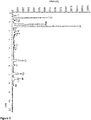
- Figure 2 shows schematically an apparatus for measuring fatigue resistance.
- FIG. 3 shows schematically a pacemaker 50 with a pulse generator 70, and a lead 140 comprising an electrode 60.
- the lead 140 connects the pulse generator 70 and the heart tissue via the electrode 60.
- Figure 4 shows a cross sectional image of a wire of material according to example 2 (comparative) as observed by backscattered electron imaging according to the test method. A dark inclusion is indicated with an arrow.
- Figure 5 shows a cross sectional image of a wire of material according to example 2 (comparative) as observed by backscattered electron imaging according to the test method.
- Figure 5 shows the same image as figure 4 , but at higher magnification. A dark inclusion is indicated with the reference mark #A1.
- Figure 6 shows an analysis of elemental composition by energy dispersive x-ray spectroscopy according to the fracture surface analysis test method of the surface of an inclusion in a wire of material according to example 2 (comparative).
- the surface analysed is the inclusion indicated as #A1 in figure 5 .
- the analysis shows the presence of Al and Mg impurities and also of entities with a Cr-O bond.
- Figure 7 shows a cross sectional image of a wire of material according to example 2 (comparative) as observed by backscattered electron imaging according to the test method. A dark inclusion is indicated with the reference mark #A1.
- Figure 8 shows a cross sectional image of a wire of material according to example 2 (comparative) as observed by backscattered electron imaging according to the test method.
- the surface shown in figure 8 is taken from the same slice as that of figure 7 .
- Figure 9 shows a cross sectional image of a wire of material according to example 2a (comparative) with an Ag core, as observed by backscattered electron imaging according to the test method. A dark inclusion is indicated with an arrow.
- Figure 10 shows a cross sectional image of a wire of material according to example 2a (comparative) with an Ag core, as observed by backscattered electron imaging according to the test method.
- Figure 10 shows the same image as figure 9 , but at higher magnification. A dark inclusion is indicated with the reference mark #A2.
- Figure 11 shows an analysis of elemental composition by energy dispersive x-ray spectroscopy according to the fracture surface analysis test method of the surface of an inclusion in a wire of material according to example 2a (comparative) with an Ag core.
- the surface analysed is the inclusion indicated as #A2 in figure 10 .
- the analysis shows the presence of Al impurities and also of entities with a Cr-O bond.
- Figure 12 shows a plot of fatigue results for a wire of material according to example 1 (inventive) and a wire of material according to example 2 (comparative).
- 1 inventive
- results are shown for 2 lots, lot A as represented by a solid circle and lot B as represented by a solid triangle.
- 2 comparativative
- results are shown for 2 lots, lot C as represented by a hollow square and lot D as represented by a hollow diamond.
- the number of cycles before failure is shown as dependent on the stress amplitude applied in the test. Outliers which performed poorly are indicated with arrows.
- Figure 13 shows a plot of fatigue results for a wire of material according to example 1a (inventive) with an Ag core and a wire of material according to example 2a (comparative) with an Ag core.
- 1a inventive
- results are shown for 3 lots, lot E as represented by a solid circle, lot F as represented by a solid triangle and lot G as represented by a solid square.
- lot H as represented by a hollow square
- lot J as represented by a hollow diamond
- lot K as represented by a cross.
- the number of cycles before failure is shown as dependent on the stress amplitude applied in the test. Outliers which performed poorly are indicated with arrows.
- the leak rate of the furnace chamber is measured using the following procedure:
- Rotating beam fatigue testing was carried out using Valley Instruments model # 100 test machine ( Figure 2 ) according to Valley Instruments Wire Fatigue Tester Model # 100 user manual (Valley Instruments (Division of Positool Technologies, Inc.), Brunswick, Ohio, USA. Fatigue Tester Model 100 Manual).
- the equipment consists of a synchronous motor rotating at 3600 rpm.
- For each test of a wire specimen a sample having a predefined length is fixed in a custom fine-wire collet at one end, looped through a complete 180 degree turn and is placed at the other end in a low-friction bushing in which it is free to rotate.
- the synchronous motor of the test device is directly clocked by a counter where the number of cycles is shown in a LCD-display.
- the fatigue testers are equipped with a sensor to detect the wire fracture which automatically stops the timer, means the display of the timer shows the number of cycles until failure. If no fracture occurs within 100 Million cycles, the test is stopped.
- the machine set-up involves calculating the desired sample length and center distance using the modulus of elasticity of the material and equations developed by Valley Instruments Company (user manual).
- Inclusions are defined as internal flaws or contaminations (such as nitrides or oxides) within the billet or rod from which the wire or tube is produced.
- the transverse inclusion size is defined as the largest dimension of an internal flaw measured on transverse cross-sections of the billet, rod or wire.
- the longitudinal inclusion size is defined as the largest dimension of an internal flaw measured on longitudinal cross-sections of the billet, rod or wire.
- a cross-section diametral line is defined as any line within the cross-section having a length equal to or greater than 95% of the true cross-section diameter.
- the billet, rod or wire is to be sectioned at each end so that there are an equal number of cross sections sampled at the one end as there are samples at the other end (number of samples taken from each end shall differ by no more than one).
- the total number of cross sections samples depends on the diameter of the billet, rod or wire and is specified in Table 1.
- the length of each cross section is to be less than its diameter.
- a cross-section diametral line is defined as any line within the cross-section having a length equal to or greater than 95% of the true cross-section diameter. Angular separation between two diametral lines on a cross- section shall be a minimum of 60 degrees.
- the number of images and the number of diametral lines depends on the diameter of the billet, rod or wire and is specified in Table 1. The total number of images is shown in Table 1 and was calculated based on the number of images per sample and the number of samples.
- Each of the images is to be inspected to detect the presence of inclusions or strings of inclusions that exceed a size of 3.0 ⁇ m in their largest dimension.
- the image inspection may be accomplished either by manual examination or by automated scanning.
- Table 1 cross section diameter of billet, rod or wire Number of diametral lines per section (no requirement for tube samples) Number of images per section Number of cross-sections Total images per lot equal to or greater than [mm] but no greater than [mm] transverse longitudinal transverse longitudinal 2.54 3.80 5 40 12 12 480 480 3.81 5.71 3 40 12 12 480 480 5.72 11.42 2 40 12 12 480 480 11.43 13.96 1 40 12 12 480 480 13.97 17.14 1 48 10 10 480 480 17.15 21.58 1 60 8 8 480 480 21.59 27.93 1 80 6 6 480 480 27.94 33.01 1 96 5 5 480 480 33.02 43.17 1 120 4 4 480 480 43.18 57.14 1 160 3 3 480 480
- the test method to analyse fracture surfaces of fatigue tested samples was Scanning electron microscopy (SEM).
- SEM Scanning electron microscopy
- a Zeiss Ultra 55 Gemini was used for the sample analysis of the present invention and comparative samples. Two imaging modes were used to analyse and illustrate the tested samples.
- Energy-dispersive X-ray spectroscopy (EDS, EDX) was used for the elemental analysis of features (inclusions/particles) found on the fatigue resistance test samples. A high-energy beam of electrons is focused onto the location of the sample being analysed. This leads to the emission of characteristic X-rays which allows the elemental composition of the feature (inclusions/particles) to be measured.
- Figures 6 and 11 show EDX scans.
- the MP35N heats were VIM-VAR melted, to minimize the impurity content and to obtain a sound ingot with good chemical uniformity and metallurgical properties.
- the chemistry of representative heats: Heat 1, Heat 2 and Heat 3 are listed in Table 3.
- the table also provides the chemistry of a VIM-VAR melted, commercially available MP35N alloy and for reference the chemical requirements per ASTM F562-13, a standard specification for wrought MP35N alloy.
- the major constituents of MP35N alloy are Co, Ni, Cr and Mo.
- the new alloy heats were melted in 2 steps.
- the first melting step was Vacuum Induction Melting (VIM).
- the VIM furnace consists of a water cooled vacuum melt chamber, an oxide ceramic crucible held in a cylindrical induction heating coil inside the melt chamber, an AC electric power supply, a vacuum pumping system, a raw material adding chamber and a cylindrical metal mold held below and offset from the crucible-induction coil assembly.
- the vacuum melt chamber, raw material adding chamber and vacuum pumping system are separated by isolation valves.
- the induction heating coil is water cooled. Electric current from the power supply passes through the induction heating coil creating a magnetic field inside the furnace. The magnetic field induces eddy currents inside the raw materials causing Joule heating. Joule heating raises the temperature of the raw materials to above their melting point.
- the magnetic field mixes the liquid raw materials to make a homogeneous alloy.
- the crucible is tilted to pour the liquid alloy from the crucible into the mold.
- the alloy cools to a solid in the mold under vacuum and is removed from the furnace.
- the alloy ingot is removed from the mold and it is prepared for re-melting.
- 136 kilograms of elemental raw materials were placed in the furnace in proportions calculated to make the aim chemistry.
- the VIM furnace was closed and pumped down to ⁇ 0.00001 bar.
- a leak-up rate was measured after reaching the desired vacuum pressure level to ensure a vacuum tight furnace.
- the leak-up rate was ⁇ 0.00001 bar/min. Electric power was applied to the induction heating coil.
- the VAR furnace consists of water cooled vacuum chamber, a 203.2 mm diameter water cooled copper crucible, a direct current electric power supply, a vacuum pumping system, isolation valves and a computer based electrical system to monitor and control the application of current to the electrode inside the vacuum chamber.
- the furnace was pumped down to ⁇ 0.000006 bar before carrying out the leak-up rate test. A leak rate of ⁇ 0.000006 bar /min was obtained.
- the electrode was moved to a close proximity to the bottom of the crucible. Electric power was applied at a level to cause an electric arc to be struck between the crucible bottom and the alloy electrode. The electric arc causes the electrode to melt and drip into the bottom of the crucible creating a liquid metal pool that solidifies as the arc moves away from the molten pool. The process was continued at a controlled rate until the electrode was consumed. The power was turned off and the ingot was cooled under vacuum. The ingot was removed from the furnace for processing to product.
- the as-cast ingot was charged into a gas-fired front opening box furnace with ambient air atmosphere.
- the furnace was preset to a temperature of 815°C.
- the ingot was held for additional 4 hours prior to raising the furnace temperature.
- the ingot was then heated to 1177°C at a heating rate of 200 K per hour.
- the ingot was held for 7 hours at 1177°C for homogenization.
- the ingot was hot rolled from 203 mm to 137 mm round cornered square (RCS) billet using a 559 mm diameter Morgenshammer Mill operating at ambient temperature.
- RCS round cornered square
- the Morgenshammer Mill is a manually operated tilt table mill with 3 high rolls allowing heavy bar to be rolled alternately between the bottom and middle roll and the top and middle roll. After hot rolling the RCS billet was air cooled, abrasively ground by hand to remove surface imperfections and cut to square the ends.
- the billet was reheated and hot rolled to 51 mm RCS at 1177°C on the 559 mm Morgenshammer Mill.
- the RCS was cut to shorter lengths of final rolling on a hand operated 406 mm diameter Morgenshammer Mill with 3 high rolls. All bar manipulation on this mill is done by hand at floor level.
- the RCS was reheated at 1177°C and rolled to 33.4 mm round bars and air cooled to ambient temperature.
- the rolled bars were then reheated to 1038°C and held for 30 minutes for hot rotary straightening. After straightening, the bars were air cooled to room temperature.
- the bars were rough centerless ground, ultrasonic tested for voids and then centerless ground to final size.
- the grinded bars were gun-drilled to produce hollows for subsequent tube drawing. Tubes were filled with Ag-rods and cold-drawn using diamond dies and mineral oil. For a final wire diameter of 127 ⁇ m, the last intermediate annealing was carried out at a wire diameter of 157.5 ⁇ m at 900 - 950 °C in Argon atmosphere. From the last intermediate annealing until the final diameter of the wire, 35% cold-work were applied. Three wire lots were manufactured having UTS values of 1456, 1469 and 1474 MPa. For bare wire, the bars were further hot-rolled to 0.2 inch outer diameter followed by cold-drawing.
- the last intermediate annealing was carried out at a wire diameter of 122 ⁇ m at 1100 °C in Argon atmosphere to apply 30% cold-work to the final size.
- Two wire lots were manufactured having UTS values of 1870 and 1875 MPa.
- the wires of inventive example 1 (Lots A & B) and the cladded wires of inventive example 1a (Lots E, F & G) were made using the alloy of Heat 1 in table 3.
- the wires of comparative example 2 (lots C & D) and the cladded wires of comparative example 2a (lots H, J & K) were made from the alloy of the commercial heat in table 3 obtained from Fort Wayne Metals, Inc., USA under the trade name 35 NLT ® .
- the processed alloy was also obtainable from SAES Smart Materials, Inc. Alloys for the further examples were acquired from SAES Smart Materials, Inc. Table 3 Element Heat 1 Heat 2 Heat 3 Commercial Heat ASTM F-562-13 Wt. % Wt. % Wt. % Wt. % Wt. % Wt. % Wt.
- the microscopic inspection for microcleanliness of the inventive alloy (example 1 and example 1a with an Ag core) and of the comparative alloy (example 2 and example 2a with an Ag core) was carried out according to the procedure and test method described above.
- 4 rods with an outer diameter of 31.75 mm 5 transverse and 5 longitudinal sections were taken according to table 1 and metallographically prepared.
- the metallographically prepared sections were examined in the as-polished condition by scanning electron microscopy (SEM) using backscattered electron imaging (BEI).
- SEM scanning electron microscopy
- BEI backscattered electron imaging
- the brightness of sample features is proportional to the atomic weight of the elements constituting those features.
- present inclusions consisting of heavier elements than the surrounding matrix material appear brighter than the matrix material.
- Inclusions consisting of lighter elements than the surrounding matrix material appear darker than the matrix material.
- nonmetallic inclusions e.g. oxide or nitride inclusions
- these ceramic inclusions appear darker than the surrounding matrix material. Images were acquired at a magnification of 500X along a diametral line extending across the entire bar. Analysis of features darker and brighter than the background was conducted on the images using image analysis software to determine the maximum dimension for each detected feature. The largest dimension and area were recorded for each individual feature. The inclusions were categorized by largest dimension into 1 ⁇ m groups up to 14 ⁇ m. The total area of the dark and bright features was also calculated. Inclusions greater than 14 ⁇ m were also counted. Features smaller than 3.0 ⁇ m were not included in the measurements.
- Results of the inclusion analysis of example 1 are shown in tables 4-6.
- Results of the inclusion analysis of example 2 are shown in tables 7-10.
- Image fields showing typical dark (ceramic) inclusions are shown in Figures 4,5 , 7-10 .
- the total area of dark inclusions found is 478 ⁇ m 2 (409 ⁇ m 2 in longitudinal direction and 69 ⁇ m 2 in transverse direction).
- the total area of dark inclusions found is only 218 ⁇ m 2 (121 ⁇ m 2 in longitudinal direction and 97 ⁇ m 2 in transverse direction). So the amount of dark inclusions (Percent of total area) in example 1 (inventive) is only 4.8 ppm (0.00048 %) while in example 2 (comparative) the amount of dark inclusions is 11 ppm (0.0011 %). In terms of inclusions (micro-cleanliness) this means that example 1 (inventive) is more than 2 times cleaner than example 2 (comparative).
- Example 2 wire lot C sample C25 tested at an applied stress of 700 MPa broke after only 71,790 cycles and sample C31 tested at an applied stress of 520 MPa broke after only 145,260 cycles.
- Sample C26 tested at an applied stress of 700 MPa broke after 47,547,540 cycles and sample C29 tested at an applied stress of 700 MPa broke after 41,282,990 cycles.
- sample D27 tested at an applied stress of 700 MPa broke after only 549,227 cycles and sample D35 tested at an applied stress of 520 MPa broke after only 2,689,952 cycles.
- SEM-images of sample C25 shows an inclusion at the fracture surface.
- high peaks for Aluminium, Magnesium, Chromium and Oxygen were found. This mixed-oxide inclusion was identified as the crack initiation point for the early failure of this sample.
- An SEM-image of sample D35 also shows an inclusion at the fracture surface.
- Example 1a/Ag28% wire Three lots of example 1a/Ag28% wire (diameter 127 ⁇ m) were also tested against three lots of example 2a wire (same diameter - 127 ⁇ m). All six wire lots have comparable mechanical properties (UTS of 1456 - 1475 MPa). Table 13 - Example 1a + 28 wt. % Ag (inventive) Example 2a + 28 wt. % Ag (comparative) Batch Lot E Lot F Lot G LotH Lot J ( Fig. 10 & 11 ) Lot K UTS [MPa] 1456 1469 1474 1460 1462 1475 YM [GPa] 121 121 122 121 122 122 Elongation [%] 2.2 2.3 2.3 2.1 2.0 2.3
- SEM-images of sample J23 show an inclusion at the fracture surface.
- high peaks for Aluminium, Magnesium, Chromium and Oxygen were found. This mixed-oxide inclusion was identified as the crack initiation point for the early failure of this sample.
- SEM investigations of samples H24, J18 and K24 also showed oxide-inclusions at the fracture surface which were identified causing the early failure.
- the same elements show high peaks in EDX analysis for these three samples.
- Table 14 Example 1a + 28 wt. % Ag
Abstract
a) Cr in the range from about 10 to about 30 wt. %;
b) Ni in the range from about 20 to about 50 wt. %;
c) Mo in the range from about 2 to about 20 wt. %;
d) Co in the range from about 10 to about 50 wt. %;
wherein the A1 content of the alloy is less than about 0.01 wt. %;
wherein each wt. % is based on the total weight of the alloy.
Description
- The invention generally relates to an alloy comprising Cr, Ni, Mo and Co, preferably with tightly controlled levels of impurities. The invention further relates to a process for the preparation of an alloy, an alloy obtainable therefrom, a lead, and the use of a lead in medical devices, preferably pacemakers.
- Much investigation in recent years has been directed to a search for new high performance alloys, particularly for medical applications where a very high value is placed on reliability and materials are required which exhibit a low failure rate even over a long time period.
- Cardiac Pacemakers, Implantable Cardioverter Defibrillation Devices and Cardiac Resynchronisation Devices are applications where reliability is particularly important, especially in terms of resistance to physical fatigue and to chemical corrosion. Invasive surgery is required to implant a pacemaker into the body or remove or replace parts, and it is highly desirable for the individual components of the pacemaker to have a long working life in order to reduce the requirement for surgical intervention. Furthermore, it is desirable for the working life to have a low variance. In a heart pacemaker, one component which is exposed to a particularly high amount of stress during normal operation is the so called lead which connects the implantable pulse generator to the heart tissue. A flexible lead is required in order to connect the implantable pulse generator to the heart tissue without imposing undue physical stress on the heart and the lead flexes during normal operation, typically repetitively with a frequency on the order of that of a human heart beat. A high resistance to fatigue is therefore required in the lead in order to withstand frequent physical stress over a long period of time. A high resistance of the lead to corrosion is important not only in terms of the lifetime of the component, but also in terms of reducing toxicity to the body.
-
WO 2005026399 A1 discusses an approach to improving the properties of an alloy by reducing the content of titanium nitride and mixed metal carbonitride. -
US 2005/0051243 A1 focuses on alloys with a reduced content of nitrogen. - There persists a requirement for alloys having improved performance, particularly with regard to improving resistance to physical fatigue.
- The invention is generally based on the object of overcoming at least one of the problems encountered in the state of the art in relation to alloys.
- More specifically, the invention is further based on the object of providing an alloy having improved properties.
- One object of the invention is to provide an alloy which has improved resistance to physical fatigue, preferably also having a high corrosion resistance. Another object is to provide an alloy which can be drawn into a thin wire, preferably less than about 50 µm.
- A further object of the invention is to provide a method for the preparation of an alloy having improved properties, preferably an improved resistance to physical fatigue, preferably also having a high corrosion resistance, preferably also which can be drawn into a thin wire, more preferably less than about 50 µm.
- One object of the invention is to provide a wire having comparable tensile properties to known wire, but for which the proportion of outlying failures in fatigue resistance is reduced.
- A contribution to achieving at least one of the above described objects is made by the subject matter of the category forming claims of the invention. A further contribution is made by the subject matter of the dependent claims of the invention which represent specific embodiments of the invention.
- A contribution to achieving at least one of the above described objects is made by the following embodiments.
- |1| An alloy comprising the following alloy components:
- a) Cr in the range from about 10 to about 30 wt. %, preferably in the range from about 15 to about 25 wt. %, more preferably in the range from about 19 to about 21 wt. %;
- b) Ni in the range from about 20 to about 50 wt. %, preferably in the range from about 30 to about 45 wt. %, more preferably in the range from about 33 to about 37 wt. %;
- c) Mo in the range from about 2 to about 20 wt. %, preferably in the range from about 5 to about 15 wt. %, more preferably in the range from about 9 to about 10.5 wt. %;
- d) Co in the range from about 10 to about 50 wt. %, preferably in the range from about 20 to about 40 wt. %, more preferably in the range from about 33 to about 37 wt. %;
wherein each wt. % is based on the total weight of the alloy. - |2| The alloy according to embodiment |1|, wherein the content of Mg is less than about 0.005 wt. %, preferably less than about 0.0001 wt. %, more preferably less than about 0.00001 wt. %, based on the total weight of the alloy.
- |3| The alloy according to embodiment |1| or |2|, wherein the content of Ca is less than about 0.005 wt. %, preferably less than about 0.0001 wt. % more preferably less than about 0.00001 wt. %, based on the total weight of the alloy.
- |4| The alloy according to any of the preceding embodiments, wherein the content of Ce is less than about 0.005 wt. %, preferably less than about 0.0001 wt. % more preferably less than about 0.00001 wt. %, based on the total weight of the alloy.
- |5| The alloy according to any of the preceding embodiments, wherein the content of Ti is less than about 0.1 wt. %, preferably less than about 0.01 wt. % more preferably less than about 0.001 wt. %, further more preferably less than about 0.0005 wt. %, based on the total weight of the alloy.
- |6| The alloy according to any of the preceding embodiments, wherein the content of Fe is in the range from about 0.0001 to about 1 wt. %, preferably in the range from about 0.0005 to about 0.1 wt. %, more preferably in the range from about 0.001 to about 0.05 wt. %, based on the total weight of the alloy.
- |7| The alloy according to any of the preceding embodiments, wherein at least one of the following is satisfied:
- a) The content of C in the alloy is less than about 0.1 wt. %, preferably less than about 0.08 wt. % more preferably less than about 0.05 wt. %
- b) The content of B in the alloy is less than about 0.01 wt. %, preferably less than about 0.001 wt%, more preferably less than about 0.0002 wt. %;
- c) The content of P in the alloy is less than about 0.01 wt. %, preferably less than about 0.005 wt. %, more preferably less than about 0.001 wt. %, further more preferably less than about 0.0005 wt. %;
- d) The content of S in the alloy is less than about 0.005 wt. %, preferably less than about 0.003 wt. %, more preferably less than about 0.002 wt. %, further more preferably less than about 0.0008 wt. %;
- |8| The alloy according to any of the preceding embodiments, wherein at least one of the following is satisfied:
- a) The content of Mn in the alloy is less than about 0.05 wt. %, preferably less than about 0.005 wt. %, more preferably less than about 0.001 wt. %;
- b) The content of Si in the alloy is less than about 0.05 wt. %, preferably less than about 0.03 wt. %, more preferably less than about 0.02 wt. %;
- |9| The alloy according to any of the preceding embodiments, wherein at least one of the following is satisfied:
- a) The content of O in the alloy is in the range from about 0.0001 to about 0.05 wt. %, preferably in the range from about 0.0001 to about 0.03 wt. %, more preferably in the range from about 0.0001 to about 0.01 wt. %;
- b) The content of N in the alloy is in the range from about 0.0001 to about 0.01 wt. %, preferably in the range from about 0.0001 to about 0.008 wt. %, more preferably in the range from about 0.0001 to about 0.005 wt. %;
- |10| The alloy according to any of the preceding embodiments, wherein at least one of the following is satisfied:
- a) The alloy contains less than about 0.01 wt. %, preferably less than about 0.005 wt. %, more preferably less than about 0.001 wt. %, O in the form of a magnesium oxide;
- b) The alloy contains less than about 0.01 wt. %, preferably less than about 0.005 wt. %, more preferably less than about 0.001 wt. %, O in the form of an aluminium oxide;
- c) The alloy contains less than about 0.01 wt. %, preferably less than about 0.005 wt. %, more preferably less than about 0.001 wt. %, O in the form of a cerium oxide.
- d) The alloy contains less than about 0.01 wt. %, preferably less than about 0.005 wt. %, more preferably less than about 0.001 wt. %, O in the form of a calcium oxide.
- e) The alloy contains less than about 0.01 wt. %, preferably less than about 0.005 wt. %, more preferably less than about 0.001 wt. %, O in the form of a chromium oxide.
- |11| A process for the preparation of an alloy comprising the following preparation steps:
- a) Provision of a mixture comprising the following components:
- i. Cr in the range from about 10 to about 30 wt. %, preferably in the range from about 15 to about 25 wt. %, more preferably in the range from about 19 to about 21 wt. %;
- ii. Ni in the range from about 20 to about 50 wt. %, preferably in the range from about 25 to about 40 wt. %, more preferably in the range from about 33 to about 37 wt. %;
- iii. Mo in the range from about 2 to about 20 wt. %, preferably in the range from about 5 to about 15 wt. %, more preferably in the range from about 9 to about 10.5 wt. %;
- iv. Co in the range from about 10 to about 50 wt. %, preferably in the range from about 20 to about 40 wt. %, more preferably in the range from about 33 to about 37 wt. %.
- b) Melting the mixture in a vacuum induction melting step in order to obtain a first melt, in one aspect of this embodiment, one or more further vacuum induction melting steps are carried out;
- c) Solidifying the first melt in order to obtain a first solid;
- d) Melting the first solid in a vacuum arc melting step in order to obtain a further melt;
- e) Solidifying the further melt in order to obtain a further solid.
- a) Provision of a mixture comprising the following components:
- |12| The process according to embodiment |11|, wherein pressure in step b) is below about 0.1 bar, preferably below about 0.05 bar, more preferably below about 0.01 bar.
- |13| The process according to embodiment |11| or |12|, wherein the leak rate in step b) is below about 0.1 bar / min, preferably below about 0.05 bar / min, more preferably below about 0.01 bar / min.
- |14| The process according to any of the embodiments |11| to |13|, wherein the pressure in step d) is below about 0.05 bar, preferably below about 0.01 bar, more preferably below about 0.005 bar.
- |15| The process according to any of the embodiments |11| to |14|, wherein the leak rate in step d) is below about 0.05 bar / min, preferably less than about 0.01 bar / min, more preferably less than about 0.005 bar / min.
- |16| The process according to any of the embodiments |11| to |15|, further comprising a homogenisation step carried out at a temperature in the range from about 900 to about 1300 °C, preferably in the range from about 1000 to about 1250 °C, more preferably in the range from about 1100 to about 1225 °C.
- |17| The process according to any of the embodiments |11| to |16|, further comprising a cogging step carried out at a temperature in the range from about 900 to about 1300 °C, preferably in the range from about 1000 to about 1250 °C, more preferably in the range from about 1100 to about 1225 °C.
- |18| The process according to any of the embodiments |11| to |17|, further comprising a finish roll step carried out at a temperature in the range from about 900 to about 1300 °C, preferably in the range from about 1000 to about 1250 °C, more preferably in the range from about 1100 to about 1225 °C.
- |19| The process according to any of the embodiments |11| to |18|, further comprising a straightening step. In one aspect of this embodiment, the straightening is a hot straightening, preferably carried out at a temperature in the range from about 900 to about 1200 °C, preferably in the range from about 950 to about 1100 °C, more preferably in the range from about 1000 to about 1075 °C. In one aspect of this embodiment, the straightening is a cold straightening, preferably carried out at ambient temperature, preferably at a temperature in the range from about 10 to about 100 °C, more preferably in the range from about 15 to about 80 °C, most preferably in the range from about 20 to about 50 °C.
- |20| An alloy obtainable by a process according to any of the embodiments |11| to 1191.
- |21| An electrical wire comprising an alloy according to any of the embodiments |1| to |10| or |20|.
- |22| A medical device comprising a wire according to embodiment 1211.
- |23| A pacemaker, an implantable cardioverter defibrillator, a cardiac resyncronisation device, a neuromodulation device, a cochlea implant or any other implantable stimulation device comprising a wire according to embodiment 1211.
- Preferred alloys according to the invention comprise two or more elements, preferably as a solid mixture, preferably with an enthalpy of mixing of the constituent elements of less than about 10 KJ/mol, preferably less than about 5 KJ/mol, more preferably less than about 1 KJ/mol. Preferred alloys comprise Cr, Ni, Mo and Co as major constituents, preferably with at least about 95 wt. %, more preferably at least about 99 wt. %, further more preferably at least about 99.9 wt. %, more preferably at least about 99.95 wt. % of the alloy being Cr, Ni, Mo and Co.
- A composition of the alloy is preferred which improves favourable properties of the alloy, in particular resistance to fatigue and/or corrosion resistance, preferably both.
- It is preferred for the properties of the alloy to be improved by limiting the content of impurities or limiting the content of a combination of different impurities, preferably according the embodiments of the invention.
- It is preferred that there be a low, preferably zero concentration of inclusions in the alloy. This is preferably achieved by limiting the content of impurities. In one embodiment it is preferred that the alloy contain less than about 0.01 %, preferably less than about 0.005 %, more preferably less than about 0.001 % inclusions. The % of inclusions is preferably determined using the microscopic inspection method given in the test methods. Content of inclusions as % is there determined as the proportion of the cross sectional area of the sample surface made up of inclusions. In some instances, the alloy comprises a low, preferably a zero concentration of inorganic non-metallic solid inclusions, more preferably of inorganic oxide inclusions. Inorganic oxides in this context can refer to metal oxides, non-metal oxides and metalloid-oxides. In some cases the the alloy comprises a low, preferably a zero concentration of inclusions comprising one or more selected from the group consisting of: Si, Al, Ti, Zr and B; preferably selected form the group consisting of: Si Ti, and Al.
- In one embodiment, one or more treating material(s) is/are contacted with the mixture of the process in order to remove oxygen from the mixture of the process, preferably by incorporation of the oxygen into a dross and removal of the dross. Preferred treating materials in this context comprise one or more selected from the list consisting of: Al, Mg, Ca and Ce; preferably in the form of an element and/or in the form of an alloy, wherein the alloy preferably contains a further metal being selected from group consisting of Cr, Ni, Mo and Co or at least two thereof, preferably Ni.
- In order to achieve the preferred concentrations of constituents of the alloy, described above in the embodiments, the skilled person may vary the proportions of starting materials employed in the preparation process. The proportions of the starting materials might not be equal to the proportions of constituents of the product, due to net loss or gain during the preparation process.
- The process for the preparation of the alloy preferably comprises the following steps:
- a) A vacuum induction melting step;
- b) A vacuum arc melting step.
- In one embodiment of the invention, the process comprises two or more vacuum induction melting steps. In another embodiment of the invention, the process comprises two or more vacuum melting steps. In another embodiment of the invention, the process comprises two or more vacuum induction melting steps and two or more vacuum arc melting steps.
- In preferred embodiments of the invention, the process further comprises one or more of the following steps:
- c) An electro-slag melting step
- d) A homogenisation step
- e) A cogging step
- f) A finish roll step
- g) A straightening step
- In preferred embodiments, the process comprises a combination of the above steps selected from the list consisting of: c), d), e), f), g), c)+d), c)+e), c)+f), c)+g), d)+e), d)+f), d)+g), e)+f), e)+g), f)+g), c)+d)+e), c)+d)+f), c)+d)+g), c)+e)+f), c)+e)+g), c)+f)+g), d)+e)+f), d)+e)+g), d)+f)+g), e)+f)+g), d)+e)+f)+g), c)+e)+f)+g), c)+d)+f)+g), c)+d)+e)+g), c)+d)+e)+f) and c)+d)+e)+f)+g).
- In one embodiment of the invention, one or more of the steps c)-g) is carried out two or more times.
- In preferred vacuum induction melting steps, a material is heated by inducing an electric current in the material, preferably by electromagnetic induction. The pressure in the vacuum induction melting step is preferably below about 0.1 mbar, more preferably below about 0.01 mbar, most preferably below about 0.001 mbar. The vacuum induction melt step is preferably carried out in an oven, preferably with a low leak rate, preferably below about 0.1 mbar·l/s, more preferably below about 0.01 mbar·l/s, most preferably below about 0.001 mbar·l/s. The leak rate is preferably tested before the vacuum induction melting step by evacuating the oven, closing the valves of the oven, and measuring the rate of increase of pressure in the oven.
- In one embodiment of the invention, the vacuum induction melting step is carried out in an inert atmosphere, preferably argon, preferably an atmosphere comprising at least about 90 wt. %, more preferably at least about 99 wt. %, most preferably at least about 99.9 wt. % of inert gas, preferably argon. In one aspect of this embodiment, the oven is evacuated and inert gas, preferably argon, introduced into the oven before melting. In one aspect of this embodiment, the pressure in the vacuum induction melting step is in the range from about 1 to about 200 mbar, preferably in the arrange from about 10 to about 150 mbar, most preferably in the range from about 20 to about 100 mbar.
- In preferred vacuum arc melting steps, a material is heated by passing an electrical current through the material, preferably with an electrical power in the range from about 300 to about 1200 W/kg, more preferably in the range from about 400 to about 1000 W/kg, most preferably in the range from about 450 to about 900 W/kg, based on the mass of material heated. The pressure in the vacuum arc melting step is preferably below about 0.1 mbar, more preferably below about 0.01 mbar, most preferably below about 0.001 mbar. The vacuum arc melt step is preferably carried out in an oven, preferably with a low leak rate, preferably below about 0.1 mbar·l/s, more preferably below about 0.05 mbar·l/s, most preferably below about 0.01 mbar·l/s. The leak rate is preferably tested before the vacuum arc melting step by evacuating the oven, closing the valves of the oven, and measuring the rate of increase of pressure in the oven. In one embodiment of the invention, the vacuum arc melting step is carried out in an inert atmosphere, preferably argon, preferably an atmosphere comprising at least about 90 wt. %, more preferably at least about 99 wt. %, most preferably at least about 99.9 wt. % of inert gas, preferably argon. In one aspect of this embodiment, the oven is evacuated and inert gas, preferably argon, introduced into the oven before melting. In one aspect of this embodiment, the pressure in the vacuum arc melting step is in the range from about 0.001 to about 0.2 bar, preferably in the range from about 0.01 to about 0.15 bar, most preferably in the range from about 0.05 to about 0.1 bar.
Homogenisation steps according to the invention preferably allow reduction of inhomogeneity in a material, preferably by heating. In preferred homogenisation steps according to the invention, a material is heated to a temperature which is below its melting temperature, preferably below its incipient melting temperature. It is preferred that the material be homogenised for a duration in the range from about 10 min. to about 20 hours, more preferably in the range from about 3 hours to about 10 hours, most preferably in the range from about 5 hours to about 8 hours. Homogenisation is preferably carried out in a vacuum or in a gaseous atmosphere, preferably in a gaseous atmosphere. It is preferred that the homogenisation step be carried out close to atmospheric pressure, preferably in the range from about 0.5 to about 1.5 bar, more preferably in the range from about 0.8 to about 1.2 bar, most preferably in the range from about 0.9 to about 1.1 bar. In one preferred embodiment, the homogenisation step is carried out in air. - In preferred cogging steps according to the invention, the porosity or grain size or both of a material are reduced, preferably at elevated temperatures, preferably below the melting point of the material, preferably with the application of compressive force. Compressive forces may be applied locally or in a delocalised manner, preferably by one or more selected from the group consisting of: rolling, pressing, beating and turning. Where the material to be cogged has a mass below about 10 kg, preferably below about 8 kg, more preferably below about 5 kg, rolling is preferred. Where the material to be cogged has a mass above about 10 kg, preferably above about 20 kg, more preferably above about 30 kg, beating or turning is preferred. It is preferred that the smallest dimension of the material is reduced during the cogging process.
- Preferred finish roll steps according to the invention reduce the smallest dimension of the material, preferably by passing the material through one or more pairs of rolls, preferably below the melting point of the material, more preferably below its incipient melting point. In one embodiment, the finish roll step reduces the porosity or grain size of the material, preferably both.
- Straightening preferably reduces the physical curvature of the material, preferably so as to facilitate further grinding or machining steps. Straightening is preferably carried out by applying compressive force. The straightening step is preferably carried out below the melting point of the material, more preferably below its incipient melting point. In one embodiment, the process comprises a hot straightening step. In one embodiment, the process comprises a cold straightening step, preferably carried out at around ambient temperature. Cold straightening is preferably carried out at a temperature in the range from about 10 to about 100 °C, more preferably in the range from about 15 to about 80 °C, most preferably in the range from about 20 to about 50 °C.
- In this text, reference is made variously to a coated or cladded wire, which comprises a wire core and a shell. The shell might be coated or cladded onto the core wire.
- A preferred lead according to the invention comprises at least one proximal connector, at least one distal electrode and a flexible elongated conductor that is electrically connecting the electrode(s) to the connector(s). Preferably the elongated conductor is a coiled wire or a cable and comprises the alloy according to the invention.
- A contribution to achieving at least one of the above mentioned objects is made by a wire comprising an alloy according to the invention, preferably having a thickness in the range from about 10 to about 50 µm, preferably in the range from about 15 to about 35 µm. In one embodiment, the wire further comprises silver metal.
- In one embodiment, the lead comprises a silver core and an alloy according to the invention, preferably present as a shell surrounding the silver core.
- A contribution to achieving at least one of the above mentioned objects is made by a lead comprising one or more wires according to the invention, preferably grouped into two or more cables, each cable comprising two or more wires according to the invention. In one embodiment, the cables have a thickness in the range from about 0.05 to about 0.5 mm, preferably in the range from about 0.1 to 0.4 mm.
- A contribution to achieving at least one of the above mentioned problems is made by a medical device, preferably a pacemaker, comprising a lead according to the invention. A preferred pacemaker comprises:
- An implantable pulse generator;
- One or more leads according to the invention.
- In one embodiment, the pacemaker comprises one or more pulsers.
- In one embodiment, the pacemaker comprises one or more energy cells, preferably one or more electrical cells.
- A preferred process for the preparation of a wire according to the invention comprises the steps:
- a) Providing a tube of alloy according to the invention;
- b) At least partially filling the tube with Ag to obtain a composite;
- c) One or more drawing steps to reduce the diameter of the composite;
- d) Optionally one or more annealing steps to soften the composite and facilitate drawing.
- In one embodiment of the invention, the Ag content of the wire obtainable by the process is in the range from about 15 to about 50 wt. %, preferably in the range from about 17.5 to about 45.7 wt. %, more preferably in the range from about 28.7 to about 37.7 wt. %, based on the total weight of the wire.
- In one embodiment the diameter of the wire obtainable by the process is in the range from about 5 to about 50 µm, preferably in the range from about 15 to about 35 µm.
- In one embodiment, the filling degree of silver in the wire obtainable by the process is in the range from about 15 % to about 41 %, preferably in the range from about 20 % to about 35 %, more preferably in the range from about 23 % to about 33 %.
- The invention is now further illustrated using figures which are not to be considered as limiting the scope of the invention.
-
Figure 1 shows schematically a lead according to the invention. -
Figure 2 shows schematically an apparatus for measuring fatigue resistance. -
Figure 3 shows schematically a pacemaker comprising a lead according to the invention. -
Figure 4 shows a cross sectional image of a wire of material according to example 2 (comparative). -
Figure 5 shows a cross sectional image of a wire of material according to example 2 (comparative). -
Figure 6 shows an analysis of elemental composition by energy dispersive x-ray spectroscopy of an inclusion in a wire of material according to example 2 (comparative). -
Figure 7 shows a cross sectional image of a wire of material according to example 2 (comparative). -
Figure 8 shows a cross sectional image of a wire of material according to example 2 (comparative). -
Figure 9 shows a cross sectional image of a wire of material according to example 2a (comparative) with an Ag core. -
Figure 10 shows a cross sectional image of a wire of material according to example 2a (comparative) with an Ag core. -
Figure 11 shows an analysis of elemental composition by energy dispersive x-ray spectroscopy of an inclusion in a wire of material according to example 2a (comparative) with an Ag core. -
Figure 12 shows a plot of fatigue results for a wire of material according to example 1 (inventive) and a wire of material according to example 2 (comparative). -
Figure 13 shows a plot of fatigue results for a wire of material according to example 1a (inventive) with an Ag core and a wire of material according to example 2a (comparative) with an Ag core. -
Figure 1 shows schematically a lead having acable bundle 140, which comprisescables 100. In this example, thecables 100 each comprise 7wires 10. Each wire comprises afirst region 20 and afurther region 30, wherein thefirst region 20 is interior to theregion 30 along the length of thelead 140. Thefirst region 20 is 41 area % of the cross sectional area thewire 10 and the further region is 59 area % of the cross sectional area of thewire 10, in each case based on the total cross sectional area of thewire 10. In this example, thefirst region 20 is silver. Thefurther region 30 is an alloy according to the invention. In this example, thecable bundle 140 comprises 7cables 100, eachcable 100 comprising 7wires 10. The invention is not limited to this arrangement. In particular, other arrangements ofwires 10 incables 100 and/or other arrangements ofcable bundles 140 in leads are conceivable. -
Figure 2 shows schematically an apparatus for measuring fatigue resistance. -
Figure 3 shows schematically apacemaker 50 with apulse generator 70, and a lead 140 comprising anelectrode 60. Thelead 140 connects thepulse generator 70 and the heart tissue via theelectrode 60. -
Figure 4 shows a cross sectional image of a wire of material according to example 2 (comparative) as observed by backscattered electron imaging according to the test method. A dark inclusion is indicated with an arrow. -
Figure 5 shows a cross sectional image of a wire of material according to example 2 (comparative) as observed by backscattered electron imaging according to the test method.Figure 5 shows the same image asfigure 4 , but at higher magnification. A dark inclusion is indicated with the reference mark #A1. -
Figure 6 shows an analysis of elemental composition by energy dispersive x-ray spectroscopy according to the fracture surface analysis test method of the surface of an inclusion in a wire of material according to example 2 (comparative). The surface analysed is the inclusion indicated as #A1 infigure 5 . In particular, the analysis shows the presence of Al and Mg impurities and also of entities with a Cr-O bond. -
Figure 7 shows a cross sectional image of a wire of material according to example 2 (comparative) as observed by backscattered electron imaging according to the test method. A dark inclusion is indicated with the reference mark #A1. -
Figure 8 shows a cross sectional image of a wire of material according to example 2 (comparative) as observed by backscattered electron imaging according to the test method. The surface shown infigure 8 is taken from the same slice as that offigure 7 . -
Figure 9 shows a cross sectional image of a wire of material according to example 2a (comparative) with an Ag core, as observed by backscattered electron imaging according to the test method. A dark inclusion is indicated with an arrow. -
Figure 10 shows a cross sectional image of a wire of material according to example 2a (comparative) with an Ag core, as observed by backscattered electron imaging according to the test method.Figure 10 shows the same image asfigure 9 , but at higher magnification. A dark inclusion is indicated with the reference mark #A2. -
Figure 11 shows an analysis of elemental composition by energy dispersive x-ray spectroscopy according to the fracture surface analysis test method of the surface of an inclusion in a wire of material according to example 2a (comparative) with an Ag core. The surface analysed is the inclusion indicated as #A2 infigure 10 . In particular, the analysis shows the presence of Al impurities and also of entities with a Cr-O bond. -
Figure 12 shows a plot of fatigue results for a wire of material according to example 1 (inventive) and a wire of material according to example 2 (comparative). For example 1 (inventive), results are shown for 2 lots, lot A as represented by a solid circle and lot B as represented by a solid triangle. For example 2 (comparative), results are shown for 2 lots, lot C as represented by a hollow square and lot D as represented by a hollow diamond. The number of cycles before failure is shown as dependent on the stress amplitude applied in the test. Outliers which performed poorly are indicated with arrows. -
Figure 13 shows a plot of fatigue results for a wire of material according to example 1a (inventive) with an Ag core and a wire of material according to example 2a (comparative) with an Ag core. For example 1a (inventive), results are shown for 3 lots, lot E as represented by a solid circle, lot F as represented by a solid triangle and lot G as represented by a solid square. For example 2a (comparative), results are shown for 3 lots, lot H as represented by a hollow square, lot J as represented by a hollow diamond and lot K as represented by a cross. The number of cycles before failure is shown as dependent on the stress amplitude applied in the test. Outliers which performed poorly are indicated with arrows. - For a quantitative chemical analysis of the alloy, the following methods are used:
- a) the main components of the alloy (Co, Cr, Ni, Mo) are measured by X-ray fluorescence XRF using the XRF Lab Report - S8 TIGER from the company BRUKER (Bruker AXS GmbH Ostliche Rheinbrückenstr. 49, 76187 Karlsruhe, Germany)
- b) Trace elements present in the alloy (Mn, P, Si, Fe, Ti, Al, B, Mg, Ca, Ce, Ti) are measured by glow discharge mass spectrometry (GDMS) using the ASTRUM from Nu Instruments (Nu Instruments Limited, Unit 74, Clywedog Road South, Wrexham, LL13 9XS UK.)
- c) Gas or non-metallic components in the alloy (H, O, C, N, S) are measured by carrier-gas hot extraction using the ONH836 from LECO (LECO Corporation, 3000 Lakeview Avenue, St. Joseph, Michigan 49085)
- The leak rate of the furnace chamber is measured using the following procedure:
- The Vacuum furnace chamber is evacuated to the required pressure by a vacuum pumping station. When the required pressure is reached, the pressure valve between the vacuum furnace chamber and the vacuum pumping station is closed. The pressure increase of the vacuum furnace chamber over a given length of time defines the leak rate of the equipment.
- Rotating beam fatigue testing was carried out using Valley
Instruments model # 100 test machine (Figure 2 ) according to Valley Instruments Wire FatigueTester Model # 100 user manual (Valley Instruments (Division of Positool Technologies, Inc.), Brunswick, Ohio, USA.Fatigue Tester Model 100 Manual). The equipment consists of a synchronous motor rotating at 3600 rpm. For each test of a wire specimen, a sample having a predefined length is fixed in a custom fine-wire collet at one end, looped through a complete 180 degree turn and is placed at the other end in a low-friction bushing in which it is free to rotate. The synchronous motor of the test device is directly clocked by a counter where the number of cycles is shown in a LCD-display. The fatigue testers are equipped with a sensor to detect the wire fracture which automatically stops the timer, means the display of the timer shows the number of cycles until failure. If no fracture occurs within 100 Million cycles, the test is stopped. - Valley Instruments Wire Fatigue
Tester Model # 100 user manual (Valley Instruments (Division of Positool Technologies, Inc.), Brunswick, Ohio, USA.Fatigue Tester Model 100 Manual) describes that a loop, formed by an elastic length held so that the axes of the specimen at the point of retention are exactly parallel, assumes a shape in which: - (1) The length of the loop is 2.19 times the base,
- (2) The height of the arch is always 0.835 times the base,
- (3) The minimum radius of the curvature occurs at the apex of the arch and is exactly 0.417 times the base, and
- (4) The bending stress at the point of minimum curvature bears a simple reciprocal linear relationship to any of the four physical dimensions (length, height, base, and minimum curvature).
- The following formulas express the exact relationship:


- Nomenclature:
- C = chuck to bushing distance
- d = diameter of wire
- h = height of loop
- E = modulus of elasticity
- L = length of wire external to chucks
- R = minimum of radius of curvature
- S = bending stress
- P = bushing load or lateral force at the chuck
- With the above listed formula, the bending stress S (at the peak of the loop) can be calculated by the following equation:

- The machine set-up involves calculating the desired sample length and center distance using the modulus of elasticity of the material and equations developed by Valley Instruments Company (user manual).
- Definition: Inclusions are defined as internal flaws or contaminations (such as nitrides or oxides) within the billet or rod from which the wire or tube is produced. The transverse inclusion size is defined as the largest dimension of an internal flaw measured on transverse cross-sections of the billet, rod or wire. The longitudinal inclusion size is defined as the largest dimension of an internal flaw measured on longitudinal cross-sections of the billet, rod or wire. A cross-section diametral line is defined as any line within the cross-section having a length equal to or greater than 95% of the true cross-section diameter.
- For each material lot, the billet, rod or wire is to be sectioned at each end so that there are an equal number of cross sections sampled at the one end as there are samples at the other end (number of samples taken from each end shall differ by no more than one). The total number of cross sections samples depends on the diameter of the billet, rod or wire and is specified in Table 1. The length of each cross section is to be less than its diameter.
- For each billet, rod or solid wire cross-section, non-overlapping images are to be taken at 500X magnification along diametral lines so that the total examined area per sample is at least 1.77 mm2. A cross-section diametral line is defined as any line within the cross-section having a length equal to or greater than 95% of the true cross-section diameter. Angular separation between two diametral lines on a cross- section shall be a minimum of 60 degrees. The number of images and the number of diametral lines depends on the diameter of the billet, rod or wire and is specified in Table 1.
The total number of images is shown in Table 1 and was calculated based on the number of images per sample and the number of samples. - Each of the images is to be inspected to detect the presence of inclusions or strings of inclusions that exceed a size of 3.0 µm in their largest dimension. The image inspection may be accomplished either by manual examination or by automated scanning.
Table 1 cross section diameter of billet, rod or wire Number of diametral lines per section (no requirement for tube samples) Number of images per section Number of cross-sections Total images per lot equal to or greater than [mm] but no greater than [mm] transverse longitudinal transverse longitudinal 2.54 3.80 5 40 12 12 480 480 3.81 5.71 3 40 12 12 480 480 5.72 11.42 2 40 12 12 480 480 11.43 13.96 1 40 12 12 480 480 13.97 17.14 1 48 10 10 480 480 17.15 21.58 1 60 8 8 480 480 21.59 27.93 1 80 6 6 480 480 27.94 33.01 1 96 5 5 480 480 33.02 43.17 1 120 4 4 480 480 43.18 57.14 1 160 3 3 480 480 - The test method to analyse fracture surfaces of fatigue tested samples was Scanning electron microscopy (SEM). A Zeiss Ultra 55 Gemini was used for the sample analysis of the present invention and comparative samples.
Two imaging modes were used to analyse and illustrate the tested samples. - a) SE: the detection of secondary electrons (SE) results in images with a well-defined, three-dimensional appearance. The surface topography can be illustrated in high resolution.
Figures 5 ,7 ,8 and10 are secondary electron images. - b) BSE: backscatter electrons (BSE) are used to detect contrast between areas with different chemical compositions. Heavy elements (high atomic number) backscatter electrons more strongly than light elements (low atomic number), and thus appear brighter in the image.
Figures 4 and9 are BSE images. - Energy-dispersive X-ray spectroscopy (EDS, EDX) was used for the elemental analysis of features (inclusions/particles) found on the fatigue resistance test samples. A high-energy beam of electrons is focused onto the location of the sample being analysed. This leads to the emission of characteristic X-rays which allows the elemental composition of the feature (inclusions/particles) to be measured.
Figures 6 and11 show EDX scans. - The MP35N heats were VIM-VAR melted, to minimize the impurity content and to obtain a sound ingot with good chemical uniformity and metallurgical properties. The chemistry of representative heats:
Heat 1,Heat 2 andHeat 3 are listed in Table 3. The table also provides the chemistry of a VIM-VAR melted, commercially available MP35N alloy and for reference the chemical requirements per ASTM F562-13, a standard specification for wrought MP35N alloy. The major constituents of MP35N alloy are Co, Ni, Cr and Mo. The new alloy heats were melted in 2 steps. The first melting step was Vacuum Induction Melting (VIM). The VIM furnace consists of a water cooled vacuum melt chamber, an oxide ceramic crucible held in a cylindrical induction heating coil inside the melt chamber, an AC electric power supply, a vacuum pumping system, a raw material adding chamber and a cylindrical metal mold held below and offset from the crucible-induction coil assembly. The vacuum melt chamber, raw material adding chamber and vacuum pumping system are separated by isolation valves. The induction heating coil is water cooled. Electric current from the power supply passes through the induction heating coil creating a magnetic field inside the furnace. The magnetic field induces eddy currents inside the raw materials causing Joule heating. Joule heating raises the temperature of the raw materials to above their melting point. The magnetic field mixes the liquid raw materials to make a homogeneous alloy. The crucible is tilted to pour the liquid alloy from the crucible into the mold. The alloy cools to a solid in the mold under vacuum and is removed from the furnace. The alloy ingot is removed from the mold and it is prepared for re-melting.
For the example heats, 136 kilograms of elemental raw materials were placed in the furnace in proportions calculated to make the aim chemistry. The VIM furnace was closed and pumped down to ≤ 0.00001 bar. A leak-up rate was measured after reaching the desired vacuum pressure level to ensure a vacuum tight furnace. The leak-up rate was ≤ 0.00001 bar/min. Electric power was applied to the induction heating coil. Once the melt was in progress, the vacuum level was recorded at specified intervals to monitor the progress of melting and the mixing and reaction of all of the raw materials. When the reactions ceased as indicated by a constant vacuum pressure level, the heat was poured into a 152.4 mm diameter cylindrical mold.
Each heat was subsequently re-melted by a Vacuum Arc Re-melting (VAR) process to make an 203.2 mm diameter ingot. The VAR furnace consists of water cooled vacuum chamber, a 203.2 mm diameter water cooled copper crucible, a direct current electric power supply, a vacuum pumping system, isolation valves and a computer based electrical system to monitor and control the application of current to the electrode inside the vacuum chamber. The furnace was pumped down to ≤ 0.000006 bar before carrying out the leak-up rate test. A leak rate of ≤ 0.000006 bar /min was obtained. The electrode was moved to a close proximity to the bottom of the crucible. Electric power was applied at a level to cause an electric arc to be struck between the crucible bottom and the alloy electrode. The electric arc causes the electrode to melt and drip into the bottom of the crucible creating a liquid metal pool that solidifies as the arc moves away from the molten pool. The process was continued at a controlled rate until the electrode was consumed. The power was turned off and the ingot was cooled under vacuum. The ingot was removed from the furnace for processing to product.
The as-cast ingot was charged into a gas-fired front opening box furnace with ambient air atmosphere. The furnace was preset to a temperature of 815°C. Upon equilibration of furnace temperature, the ingot was held for additional 4 hours prior to raising the furnace temperature. The ingot was then heated to 1177°C at a heating rate of 200 K per hour. The ingot was held for 7 hours at 1177°C for homogenization. After homogenization, the ingot was hot rolled from 203 mm to 137 mm round cornered square (RCS) billet using a 559 mm diameter Morgenshammer Mill operating at ambient temperature. The Morgenshammer Mill is a manually operated tilt table mill with 3 high rolls allowing heavy bar to be rolled alternately between the bottom and middle roll and the top and middle roll. After hot rolling the RCS billet was air cooled, abrasively ground by hand to remove surface imperfections and cut to square the ends. - The billet was reheated and hot rolled to 51 mm RCS at 1177°C on the 559 mm Morgenshammer Mill. The RCS was cut to shorter lengths of final rolling on a hand operated 406 mm diameter Morgenshammer Mill with 3 high rolls. All bar manipulation on this mill is done by hand at floor level. The RCS was reheated at 1177°C and rolled to 33.4 mm round bars and air cooled to ambient temperature. The rolled bars were then reheated to 1038°C and held for 30 minutes for hot rotary straightening. After straightening, the bars were air cooled to room temperature. The bars were rough centerless ground, ultrasonic tested for voids and then centerless ground to final size.
- For manufacturing of clad-wires, the grinded bars were gun-drilled to produce hollows for subsequent tube drawing. Tubes were filled with Ag-rods and cold-drawn using diamond dies and mineral oil. For a final wire diameter of 127 µm, the last intermediate annealing was carried out at a wire diameter of 157.5 µm at 900 - 950 °C in Argon atmosphere. From the last intermediate annealing until the final diameter of the wire, 35% cold-work were applied. Three wire lots were manufactured having UTS values of 1456, 1469 and 1474 MPa. For bare wire, the bars were further hot-rolled to 0.2 inch outer diameter followed by cold-drawing. For 102 µm final size wire, the last intermediate annealing was carried out at a wire diameter of 122 µm at 1100 °C in Argon atmosphere to apply 30% cold-work to the final size. Two wire lots were manufactured having UTS values of 1870 and 1875 MPa. The wires of inventive example 1 (Lots A & B) and the cladded wires of inventive example 1a (Lots E, F & G) were made using the alloy of
Heat 1 in table 3. The wires of comparative example 2 (lots C & D) and the cladded wires of comparative example 2a (lots H, J & K) were made from the alloy of the commercial heat in table 3 obtained from Fort Wayne Metals, Inc., USA under the trade name 35 NLT®.Table 2 Material Example 1 (inventive) Example 1a with 28 % Ag (inventive) Batch Lot A Lot B Lot E Lot F Lot G UTS [MPa] 1870 1875 1456 1469 1474 YM [GPa] 190 191 121 121 122 Elongation [%] 2.8 2.9 2.2 2.3 2.3 - The processed alloy was also obtainable from SAES Smart Materials, Inc. Alloys for the further examples were acquired from SAES Smart Materials, Inc.
Table 3 Element Heat 1 Heat 2Heat 3Commercial Heat ASTM F-562-13 Wt. % Wt. % Wt. % Wt. % Wt. % C 0.0039 0.0091 0.0106 0.005 < 0.0250 B 0.000065 0.000067 0.000008 0.01 < 0.015 P 0.00018 0.000095 0.000056 0.001 < 0.015 S 0.00056 0.00026 0.00036 0.001 < 0.010 Mn 0.00028 0.00021 0.00013 0.017 < 0.15 Si 0.0042 0.0053 0.0061 0.034 < 0.15 Al 0.00023 0.00054 0.00043 0.023 NA Mg <0.000001 0.000003 0.000005 0.001 NA Ca <0.000005 <0.000005 <0.000005 NA NA Ce <0.000001 <0.000001 <0.000001 NA NA Fe 0.021 0.023 0.023 0.08 < 1 Ti 0.00017 0.000038 0.000023 0.001 < 1 O 0.0085 0.0056 0.0035 0.0021 NA N 0.0022 0.0009 0.0007 0.0022 NA Cr 19.6 19.7 20 20.62 19-21 Ni 35.7 34.8 34.9 34.91 33-37 Mo 10 9.93 9.7 9.47 9-10.5 Co balance balance balance balance balance - The microscopic inspection for microcleanliness of the inventive alloy (example 1 and example 1a with an Ag core) and of the comparative alloy (example 2 and example 2a with an Ag core) was carried out according to the procedure and test method described above. Of 4 rods with an outer diameter of 31.75 mm, 5 transverse and 5 longitudinal sections were taken according to table 1 and metallographically prepared. The sections included a continuous plane from two surface locations and through the approximated center of the bar. The metallographically prepared sections were examined in the as-polished condition by scanning electron microscopy (SEM) using backscattered electron imaging (BEI). In BEI, the brightness of sample features is proportional to the atomic weight of the elements constituting those features. Thus, in BEI, present inclusions consisting of heavier elements than the surrounding matrix material appear brighter than the matrix material. Inclusions consisting of lighter elements than the surrounding matrix material appear darker than the matrix material. Since nonmetallic inclusions (e.g. oxide or nitride inclusions) consist of lighter elements than the alloys of example 1 and example 2, in BEI these ceramic inclusions appear darker than the surrounding matrix material. Images were acquired at a magnification of 500X along a diametral line extending across the entire bar. Analysis of features darker and brighter than the background was conducted on the images using image analysis software to determine the maximum dimension for each detected feature. The largest dimension and area were recorded for each individual feature. The inclusions were categorized by largest dimension into 1 µm groups up to 14 µm. The total area of the dark and bright features was also calculated. Inclusions greater than 14 µm were also counted. Features smaller than 3.0 µm were not included in the measurements.
- For each section, forty-eight fields of view were evaluated. For each direction, longitudinal and transverse, 480 images with a total area of 22.6 mm2 were evaluated. The samples contained features that appeared darker and brighter than the bulk material using backscattered electron imaging. The darker features have a lower mean atomic number than the background and the brighter features have a higher mean atomic number than the background.
- Results of the inclusion analysis of example 1 are shown in tables 4-6. Results of the inclusion analysis of example 2 are shown in tables 7-10. Image fields showing typical dark (ceramic) inclusions are shown in
Figures 4,5 ,7-10 . -
TABLE 4 - FEATURE COUNT TOTALS / EXAMPLE 1 Number of Features Largest Dimension [µm] Longitudinal Transverse Dark Bright Dark Bright 3.0 - 3.9 15 0 14 0 4.0 - 4.9 4 0 2 0 5.0 - 5.9 2 0 1 0 6.0 - 6.9 0 0 0 0 7.0 - 7.9 0 0 0 0 8.0 - 8.9 0 0 0 0 9.0 - 9.9 0 0 0 0 10.0 - 10.9 0 0 0 0 11.0 - 11.9 0 0 0 0 12.0 - 12.9 0 0 0 0 13.0 - 13.9 0 0 0 0 14.0 - 14.9 0 0 0 0 >14.9 0 0 0 0 Total 21 0 17 0 TABLE 5 - TOTAL INCLUSION AREA MEASUREMENTS FOR EXAMPLE 1 Area of Inclusions > 3 µm in Length for Examination Region Darker Brighter All Sample Total Percent of Total Area Total Percent of Total Area Total Percent of Total Area [µm2] [%] [µm2] [%] [µm2] [%] Longitudinal 121 0.0006 0 0.0000 121 0.0006 Transverse 97 0.0005 0 0.0000 97 0.0005 TABLE 6 - LONGEST DARK FEATURES FOR EXAMPLE 1 Feature Dimensions, [µm] Number Length Breadth Direction 1 5.6 3.0 Longitudinal 2 5.4 3.7 Longitudinal 3 5.4 2.9 Longitudinal 4 4.9 2.2 Longitudinal 5 4.7 3.6 Longitudinal 6 4.6 1.9 Longitudinal 7 4.5 2.7 Longitudinal 8 4.5 2.4 Longitudinal 9 4.1 2.4 Longitudinal 10 3.9 3.0 Longitudinal -
TABLE 7 - FEATURE COUNT TOTALS/BARS 1-10/ALL SAMPLES Number of Features Largest Dimension [µm] Longitudinal Transverse Dark Bright Dark Bright 3.0 - 3.9 25 21 6 46 4.0 - 4.9 19 7 3 11 5.0 - 5.9 7 1 1 1 6.0 - 6.9 6 - - 1 7.0 - 7.9 7 - - - 8.0 - 8.9 4 - - - 9.0 - 9.9 1 - - - 10.0 - 10.9 2 - - - 11.0 - 11.9 2 - - - 12.0 - 12.9 - - - - 13.0 - 13.9 - - - - 14.0 - 14.9 - - - - >14.9 4 - - - Total 77 29 10 59 TABLE 8 - TOTAL INCLUSION AREA MEASUREMENTS FOR EXAMPLE 2 Area of Inclusions > 3 µm in Length for Examination Region Darker Brighter All Sample Total Percent of Total Area Total Percent of Total Area Total Percent of Total Area [µm2] [%] [µm2] [%] [µm2] [%] Longitudinal 409 0.0018 75 0.0003 484 0.0021 Transverse 69 0.0003 152 0.0007 221 0.0010 TABLE 9 - LONGEST DARK FEATURES FOR EXAMPLE 2 Feature Dimensions, [µm] Number Length Breadth Direction 1 33.4 1.9 Longitudinal 2 18.9 1.6 Longitudinal 3 17.8 2.3 Longitudinal 4 15.4 1.4 Longitudinal 5 11.8 1.0 Longitudinal 6 11.1 1.1 Longitudinal 7 10.6 1.0 Longitudinal 8 10.3 1.8 Longitudinal 9 9.5 1.5 Longitudinal 10 8.9 2.2 Longitudinal TABLE 10 - LONGEST BRIGHT FEATURES FOR EXAMPLE 2 Feature Dimensions, [µm] Number Length Breadth Direction 1 6.0 1.6 Transverse 2 5.6 2.8 Longitudinal 3 5.1 1.8 Transverse 4 4.9 2.3 Transverse 5 1.9 1.8 Transverse 6 1.0 1.8 Longitudinal 7 4.6 1.3 Transverse 8 4.5 1.2 Transverse 9 4.4 1.6 Longitudinal 10 4.4 0.9 Transverse - According to Table 8 of example 2 (comparative), the total area of dark inclusions found is 478 µm2 (409 µm2 in longitudinal direction and 69 µm2 in transverse direction). According to Table 5 of example 1 (inventive), the total area of dark inclusions found is only 218 µm2 (121 µm2 in longitudinal direction and 97 µm2 in transverse direction). So the amount of dark inclusions (Percent of total area) in example 1 (inventive) is only 4.8 ppm (0.00048 %) while in example 2 (comparative) the amount of dark inclusions is 11 ppm (0.0011 %). In terms of inclusions (micro-cleanliness) this means that example 1 (inventive) is more than 2 times cleaner than example 2 (comparative).
- Two lots of wire of example 1 (dia. 102 µm) were tested against two lots of wire or example 2 (same diameter - 102 µm) having comparable mechanical properties (UTS of 1862 - 1875 MPa).
Table 11 Material Example 1 (inventive) Example 2 (comparative) Batch Lot A Lot B Lot C ( Fig. 5 &6 )Lot D UTS [MPa] 1870 1875 1862 1871 YM [GPa] 190 191 190 190 Elongation [%] 2.8 2.9 2.7 2.8 - At an applied stress of 700 MPa, the wire of all four lots reached the fatigue endurance limit, means the wire does not fail and tests are stopped after 100 Million cycles. While the wire of example 1 showed no outliers at 700 MPa and below, 4 samples of example 2 failed at less than 2.7 Million cycles and two other samples ran 40 - 50 Million cycles. All other samples tested at an applied stress of 700 MPa and below survived 100 Million cycles without rupture. For Example 2 wire lot C, sample C25 tested at an applied stress of 700 MPa broke after only 71,790 cycles and sample C31 tested at an applied stress of 520 MPa broke after only 145,260 cycles. Sample C26 tested at an applied stress of 700 MPa broke after 47,547,540 cycles and sample C29 tested at an applied stress of 700 MPa broke after 41,282,990 cycles. For example 2 wire lot D, sample D27 tested at an applied stress of 700 MPa broke after only 549,227 cycles and sample D35 tested at an applied stress of 520 MPa broke after only 2,689,952 cycles. SEM-images of sample C25 shows an inclusion at the fracture surface. In EDX analysis, high peaks for Aluminium, Magnesium, Chromium and Oxygen were found. This mixed-oxide inclusion was identified as the crack initiation point for the early failure of this sample. An SEM-image of sample D35 also shows an inclusion at the fracture surface. Again, in EDX analysis, high peaks for Aluminium, Magnesium, Chromium and Oxygen were found. Also this mixed-oxide inclusion can be identified as the crack initiation point for the early failure of this sample. SEM investigations of samples C31 and D27 also showed oxide-inclusions at the fracture surface which were identified causing the early failure. For both samples, the same elements (Aluminium, Magnesium, Chromium, Oxygen) show high peaks in EDX analysis for these two samples.
Table 12 stress level [MPa] Example 1 (inventive) (Lot A) Example 1 (inventive) (Lot B) Example 2 (comparative) (Lot C) Example 2 (comparative) (Lot D) No. of cycles No. of cycles No. of cycles No. of cycles 1430 21092 66720 20700 35130 1430 12740 63781 22140 57120 1430 28919 59140 36120 32460 1430 19334 37942 23550 35010 1430 18119 39178 18270 28996 1430 21983 22380 18150 33313 1040 38670 128644 136680 149971 1040 58474 218106 1004289 308580 1040 46980 194108 8656363 80766 1040 34806 41310 107640 178770 1040 38045 539089 7856526 74323 1040 39120 290101 6852041 127650 880 5888420 4715690 39485962 72523366 880 4233055 5816670 102020453 100000000 880 6324748 2144125 100800000 6171230 880 13571905 2068519 114000000 4407264 880 8824316 1725656 101000000 102000000 880 7680042 1815390 100000000 57462763 800 104700000 40051186 - - 800 96874223 16938278 - - 800 59716187 26518613 - - 800 54411683 79084889 - - 800 64971417 46467823 - - 800 100000000 24231864 - - 700 103000000 105000000 71790 100000000 700 109852488 97119288 47547540 100000000 700 101589761 107000000 100000000 549227 700 101623566 104000000 100000000 101337563 700 102000000 101000000 41282990 100000000 700 103000000 103000000 100000000 100000000 520 100000000 100000000 145260 100000000 520 118987000 106000000 110800000 110800000 520 102064330 102000000 101000000 101000000 520 100963860 100613526 100500000 100500000 520 100845911 100845911 108000000 2689952 520 101009712 101006089 100000000 112000000 - These fatigue test results are plotted in
Figure 12 . As can be seen from this plot, lots C and D (comparative) show significantly more undesired outliers that for lots A and B (inventive). - Three lots of example 1a/Ag28% wire (diameter 127 µm) were also tested against three lots of example 2a wire (same diameter - 127 µm). All six wire lots have comparable mechanical properties (UTS of 1456 - 1475 MPa).
Table 13 - Example 1a + 28 wt. % Ag (inventive) Example 2a + 28 wt. % Ag (comparative) Batch Lot E Lot F Lot G LotH Lot J ( Fig. 10 &11 )Lot K UTS [MPa] 1456 1469 1474 1460 1462 1475 YM [GPa] 121 121 122 121 122 122 Elongation [%] 2.2 2.3 2.3 2.1 2.0 2.3 - At an applied stress of 414 MPa, the wire of all four lots reached the fatigue endurance limit, means the wire does not fail and tests are stopped after 100 Million cycles. While example 1a /Ag28% wire showed no outliers at 414 MPa and below, 4 samples of example 2a /Ag28% wire failed at less than 1.4 Million cycles. All other samples tested at an applied stress of 414 MPa and below survived 100 Million cycles without rupture. For example 2a /Ag28% wire lot H, sample H24 tested at an applied stress of 414 MPa broke after only 1,041,679 cycles. Sample J18 tested at an applied stress of 518 MPa broke after 588,028 cycles and sample J23 tested at an applied stress of 414 MPa broke after 263,488 cycles. Sample K24 tested at an applied stress of 414 MPa broke after 1,355,189 cycles. As an example, SEM-images of sample J23 show an inclusion at the fracture surface. In EDX analysis, high peaks for Aluminium, Magnesium, Chromium and Oxygen were found. This mixed-oxide inclusion was identified as the crack initiation point for the early failure of this sample. SEM investigations of samples H24, J18 and K24 also showed oxide-inclusions at the fracture surface which were identified causing the early failure. For all three samples, the same elements (Aluminium, Magnesium, Chromium, Oxygen) show high peaks in EDX analysis for these three samples.
Table 14 Example 1a + 28 wt. % Ag Example 2a + 28 wt. % Ag lot E lot F lot G lot H lot J lot K stress level [MPa] No. of cycles No. of cycles No. of cycles No. of cycles No. of cycles No. of cycles 969 31,887 33,065 21,487 47,982 38,148 32,926 969 29,321 28,116 23,461 43,661 41,085 20,818 969 32,555 29,941 28,763 30,298 33,187 32,299 969 26,918 23,418 18,464 37,888 36,247 38,901 969 22,089 30,467 20,198 43,092 41,944 42,978 725 246,766 231,412 114,746 74,414 235,494 109,597 725 199,054 189,441 123,746 79,498 128,377 92,419 725 287,665 262,994 168,374 94,638 118,922 91,877 725 200,822 186,242 145,355 75,062 162,522 102,834 725 500,045 290,377 169,176 62,082 238,611 99,864 580 1,405,296 1,612,743 979,651 409,644 6,780,968 311,974 580 1,077,510 1,131,168 1,846,396 668,132 12,545,505 8,369,715 580 8,201,513 993,416 1,684,673 1,031,447 1,945,002 3,001,478 stress level [MPa] No. of cycles No. of cycles No. of cycles No. of cycles No. of cycles stress level [MPa] 580 2,511,763 2,197,173 639,464 342,282 2,639,912 219,634 580 841,436 884,196 2,076,465 3,539,353 8,566,249 2,009,899 518 40,051,186 86,414,732 71,763,385 100,000,000 100,000,000 100,000,000 518 100,000,000 78,411,674 83,944,821 100,000,000 100,000,000 100,000,000 518 79,084,889 100,000,000 35,946,337 100,000,000 588,028 100,000,000 518 46,467,823 100,000,000 100,000,000 100,000,000 100,000,000 100,000,000 518 100,000,000 87,867,423 54,676,179 100,000,000 100,000,000 100,000,000 414 100,000,000 100,000,000 100,000,000 100,000,000 100,000,000 100,000,000 414 100,000,000 100,000,000 100,000,000 100,000,000 100,000,000 100,000,000 414 100,000,000 100,000,000 98,674,345 100,000,000 263,488 100,000,000 414 100,000,000 100,000,000 100,000,000 1,041,679 100,000,000 1,355,189 414 100,000,000 100,000,000 96,674,523 100,000,000 100,000,000 100,000,000 329 100,000,000 100,000,000 100,000,000 - - - 329 100,000,000 100,000,000 100,000,000 - - - 329 100,000,000 100,000,000 100,000,000 - - - 329 100,000,000 100,000,000 100,000,000 - - - 329 100,000,000 100,000,000 100,000,000 - - - - These fatigue test results are plotted in
Figure 13 . As can be seen from this plot, lots H, J and K (comparative) show significantly more undesired outliers that for lots E, F and G (inventive). - A wire with thickness 25 µm was prepared according to the method described above and with compositions of the alloy as given in table 3. The wires were arranged into a lead as described in
figure 1 . The leads were tested for fatigue resistance and for impurity inclusions. The results are shown in table 15.Table 15 Example Fatigue resistance Purity from inclusions Heat 1 ++ ++ Heat 2++ ++ Heat 3++ ++ Commercial heat - - ++ = very good, - = poor -
- 10
- Wire
- 20
- First region
- 30
- Further region
- 50
- Pacemaker
- 60
- Electrode unit
- 70
- Electronic unit
- 100
- Cable
- 110
- First mass
- 120
- Body
- 130
- Precursor
- 140
- Lead/Cable bundle
- C
- chuck to bushing distance
- H
- height of loop
- R
- minimum of radius of curvature
- P
- bushing load or lateral force at the chuck
- #A1
- Dark inclusion
Claims (22)
- An alloy comprising the following alloy components:a) Cr in the range from about 10 to about 30 wt. %;b) Ni in the range from about 20 to about 50 wt. %;c) Mo in the range from about 2 to about 20 wt. %;d) Co in the range from about 10 to about 50 wt. %;wherein the Al content of the alloy is less than about 0.01 wt. %;
wherein each wt. % is based on the total weight of the alloy. - The alloy according to claim 1, wherein the content of Mg is less than about 0.005 wt. % based on the total weight of the alloy.
- The alloy according to claim 1 or 2, wherein the content of Ca is less than about 0.005 wt. % based on the total weight of the alloy.
- The alloy according to any of the preceding claims, wherein the content of Ce is less than about 0.005 wt. % based on the total weight of the alloy.
- The alloy according to any of the preceding claims, wherein the content of Ti is less than about 0.1 wt. % based on the total weight of the alloy.
- The alloy according to any of the preceding claims, wherein the content of Fe is in the range from about 0.0001 to about 1 wt. %.
- The alloy according to any of the preceding claims, wherein at least one of the following is satisfied:a) The content of C in the alloy is less than about 0.1 wt. %;b) The content of B in the alloy is less than about 0.01 wt. %;c) The content of P in the alloy is less than about 0.01 wt. %;d) The content of S in the alloy is less than about 0.005 wt. %;each wt. % being based on the total weight of the alloy.
- The alloy according to any of the preceding claims, wherein at least one of the following is satisfied:b) The content of Mn in the alloy is less than about 0.05 wt. %;c) The content of Si in the alloy is less than about 0.05 wt. %;each wt. % being based on the total weight of the alloy.
- The alloy according to any of the preceding claims, wherein at least one of the following is satisfied:c) The content of O in the alloy is in the range from about 0.0001 to about 0.05 wt. %;d) The content of N in the alloy is in the range from about 0.0001 to about 0.01 wt. %;each wt. % being based on the total weight of the alloy.
- A process for the preparation of an alloy comprising the following preparation steps:a) Provision of a mixture comprising the following components:i. Cr in the range from about 10 to about 30 wt. %;ii. Ni in the range from about 20 to about 50 wt. %;iii. Mo in the range from about 2 to about 20 wt. %;iv. Co in the range from about 10 to about 50 wt. %;wherein each wt. % is based on the total weight of the mixture prepared for melting;b) Melting the mixture in a vacuum induction melting step in order to obtain a first melt;c) Solidifying the first melt in order to obtain a first solid;d) Melting the first solid in a vacuum arc melting step in order to obtain a further melt;e) Solidifying the further melt in order to obtain a further solid.
- The process according to claim 10, wherein pressure in step b) is below about 10-1 bar.
- The process according to claim 10 or 11, wherein the leak rate in step b) is below about 10-1 bar / min.
- The process according to any of the claims 10 to 12, wherein the pressure in step d) is below about 5 * 10-2 bar.
- The process according to any of the claims 10 to 13, wherein the leak rate in step d) is below about 5 * 10-2 bar / min.
- The process according to any of the claims 10 to 14, further comprising a homogenisation step carried out at a temperature in the range from about 900 to about 1300 °C.
- The process according to any of the claims 10 to 15, further comprising a Cog step carried out at a temperature in the range from about 900 to about 1300 °C.
- The process according to any of the claims 10 to 16, further comprising a finish roll step carried out at a temperature in the range from about 900 to about 1300 °C.
- The process according to any of the claims 10 to 17, further comprising a straightening step.
- An alloy obtainable by a process according to any of the claims 10 to 18.
- An electrical wire comprising an alloy according to any of the claims 1 to 9 or 19.
- A medical device comprising a wire according to claim 20.
- A pacemaker device comprising a wire according to claim 20.
Priority Applications (1)
| Application Number | Priority Date | Filing Date | Title |
|---|---|---|---|
| EP15201407.2A EP3181710A1 (en) | 2015-12-18 | 2015-12-18 | An alloy comprising cr, ni, mo and co for use in medical devices |
Applications Claiming Priority (1)
| Application Number | Priority Date | Filing Date | Title |
|---|---|---|---|
| EP15201407.2A EP3181710A1 (en) | 2015-12-18 | 2015-12-18 | An alloy comprising cr, ni, mo and co for use in medical devices |
Publications (1)
| Publication Number | Publication Date |
|---|---|
| EP3181710A1 true EP3181710A1 (en) | 2017-06-21 |
Family
ID=55068798
Family Applications (1)
| Application Number | Title | Priority Date | Filing Date |
|---|---|---|---|
| EP15201407.2A Pending EP3181710A1 (en) | 2015-12-18 | 2015-12-18 | An alloy comprising cr, ni, mo and co for use in medical devices |
Country Status (1)
| Country | Link |
|---|---|
| EP (1) | EP3181710A1 (en) |
Citations (3)
| Publication number | Priority date | Publication date | Assignee | Title |
|---|---|---|---|---|
| US20050051243A1 (en) | 2003-09-05 | 2005-03-10 | Forbes Jones Robin M. | Cobalt-nickel-chromium-molybdenum alloys with reduced level of titanium nitride inclusions |
| US7015392B1 (en) * | 2003-05-28 | 2006-03-21 | Accellent, Inc. | High torsional ductility wire and methods of making the same |
| US20100075168A1 (en) * | 2008-09-19 | 2010-03-25 | Fort Wayne Metals Research Products Corporation | Fatigue damage resistant wire and method of production thereof |
-
2015
- 2015-12-18 EP EP15201407.2A patent/EP3181710A1/en active Pending
Patent Citations (4)
| Publication number | Priority date | Publication date | Assignee | Title |
|---|---|---|---|---|
| US7015392B1 (en) * | 2003-05-28 | 2006-03-21 | Accellent, Inc. | High torsional ductility wire and methods of making the same |
| US20050051243A1 (en) | 2003-09-05 | 2005-03-10 | Forbes Jones Robin M. | Cobalt-nickel-chromium-molybdenum alloys with reduced level of titanium nitride inclusions |
| WO2005026399A1 (en) | 2003-09-05 | 2005-03-24 | Ati Properties, Inc. | Cobalt-nickel-chromium-molybdenum alloys with reduced level of titanium nitride inclusions |
| US20100075168A1 (en) * | 2008-09-19 | 2010-03-25 | Fort Wayne Metals Research Products Corporation | Fatigue damage resistant wire and method of production thereof |
Similar Documents
| Publication | Publication Date | Title |
|---|---|---|
| US10487377B2 (en) | Cr, Ni, Mo and Co alloy for use in medical devices | |
| EP3415649B1 (en) | A composite wire | |
| EP1664360B2 (en) | Cobalt-nickel-chromium-molybdenum alloys with reduced level of titanium nitride inclusions | |
| US11001910B2 (en) | Fatigue strength of shape memory alloy tubing and medical devices made therefrom | |
| JP6050117B2 (en) | Nickel-titanium-rare earth alloy and alloy processing method | |
| Yamanaka et al. | Effect of multipass thermomechanical processing on the corrosion behaviour of biomedical Co–Cr–Mo alloys | |
| EP3135780A1 (en) | Copper alloy manufacturing method and copper alloy | |
| US8821566B2 (en) | Alloy for medical use and medical device | |
| EP3802894B1 (en) | A beta-phase titanium and tungsten alloy | |
| US20180366239A1 (en) | Method for manufacturing a cable | |
| US20180363115A1 (en) | Method for manufacturing a composite wire | |
| EP3295969A1 (en) | Radiopaque composite wire for medical applications and method of making a radiopaque composite wire | |
| US20180363146A1 (en) | Method for manufacturing a passivated product | |
| EP3181710A1 (en) | An alloy comprising cr, ni, mo and co for use in medical devices | |
| US11511368B2 (en) | Electrically conductive tip member and method for producing the same | |
| EP3040429A1 (en) | Superelastic alloy | |
| Morita et al. | Short-Time Heat Treatment for Ti–6Al–4V Alloy Produced by Selective Laser Melting | |
| JP2019099852A (en) | NiTi-BASED ALLOY MATERIAL, MANUFACTURING METHOD OF NiTi-BASED ALLOY, WIRE MATERIAL OR TUBE MATERIAL CONSISTING OF NiTi-BASED ALLOY MATERIAL, AND MANUFACTURING METHOD THEREFOR | |
| Bradley et al. | Optimization of melt chemistry and properties of 35cobalt-35nickel-20chromium-10molybdenum alloy medical grade wire | |
| JP7008861B1 (en) | Medical Pt-W alloy | |
| Wilson et al. | Alternative beta-titanium alloys for orthodontic wires | |
| Kay et al. | Optimization of Melt Chemistry and Properties of Drawn Filled Tube (DFT) composite materials of 35Cobalt-35Nickel-20Chromium-10Molybdenum alloy (UNS R30035) Medical Grade Wire with Silver core | |
| JP2020152934A (en) | Machine component |
Legal Events
| Date | Code | Title | Description |
|---|---|---|---|
| PUAI | Public reference made under article 153(3) epc to a published international application that has entered the european phase |
Free format text: ORIGINAL CODE: 0009012 |
|
| STAA | Information on the status of an ep patent application or granted ep patent |
Free format text: STATUS: THE APPLICATION HAS BEEN PUBLISHED |
|
| AK | Designated contracting states |
Kind code of ref document: A1 Designated state(s): AL AT BE BG CH CY CZ DE DK EE ES FI FR GB GR HR HU IE IS IT LI LT LU LV MC MK MT NL NO PL PT RO RS SE SI SK SM TR |
|
| AX | Request for extension of the european patent |
Extension state: BA ME |
|
| STAA | Information on the status of an ep patent application or granted ep patent |
Free format text: STATUS: REQUEST FOR EXAMINATION WAS MADE |
|
| 17P | Request for examination filed |
Effective date: 20171220 |
|
| RBV | Designated contracting states (corrected) |
Designated state(s): AL AT BE BG CH CY CZ DE DK EE ES FI FR GB GR HR HU IE IS IT LI LT LU LV MC MK MT NL NO PL PT RO RS SE SI SK SM TR |
|
| STAA | Information on the status of an ep patent application or granted ep patent |
Free format text: STATUS: EXAMINATION IS IN PROGRESS |
|
| 17Q | First examination report despatched |
Effective date: 20190212 |
|
| STAA | Information on the status of an ep patent application or granted ep patent |
Free format text: STATUS: EXAMINATION IS IN PROGRESS |
|
| RAP1 | Party data changed (applicant data changed or rights of an application transferred) |
Owner name: SAES SMART MATERIALS, INC. Owner name: HERAEUS MEDEVIO GMBH & CO. KG |
|
| RAP3 | Party data changed (applicant data changed or rights of an application transferred) |
Owner name: RESONETICS SMART MATERIALS INC. Owner name: HERAEUS MEDEVIO GMBH & CO. KG |