EP3181405A1 - Electromagnetic wave-blocking structure in vehicle console box - Google Patents
Electromagnetic wave-blocking structure in vehicle console box Download PDFInfo
- Publication number
- EP3181405A1 EP3181405A1 EP14899674.7A EP14899674A EP3181405A1 EP 3181405 A1 EP3181405 A1 EP 3181405A1 EP 14899674 A EP14899674 A EP 14899674A EP 3181405 A1 EP3181405 A1 EP 3181405A1
- Authority
- EP
- European Patent Office
- Prior art keywords
- electromagnetic wave
- edge
- electromagnetic waves
- shielding plate
- electrical instrument
- Prior art date
- Legal status (The legal status is an assumption and is not a legal conclusion. Google has not performed a legal analysis and makes no representation as to the accuracy of the status listed.)
- Granted
Links
Images



Classifications
-
- B—PERFORMING OPERATIONS; TRANSPORTING
- B60—VEHICLES IN GENERAL
- B60R—VEHICLES, VEHICLE FITTINGS, OR VEHICLE PARTS, NOT OTHERWISE PROVIDED FOR
- B60R7/00—Stowing or holding appliances inside vehicle primarily intended for personal property smaller than suit-cases, e.g. travelling articles, or maps
- B60R7/04—Stowing or holding appliances inside vehicle primarily intended for personal property smaller than suit-cases, e.g. travelling articles, or maps in driver or passenger space, e.g. using racks
-
- B—PERFORMING OPERATIONS; TRANSPORTING
- B60—VEHICLES IN GENERAL
- B60K—ARRANGEMENT OR MOUNTING OF PROPULSION UNITS OR OF TRANSMISSIONS IN VEHICLES; ARRANGEMENT OR MOUNTING OF PLURAL DIVERSE PRIME-MOVERS IN VEHICLES; AUXILIARY DRIVES FOR VEHICLES; INSTRUMENTATION OR DASHBOARDS FOR VEHICLES; ARRANGEMENTS IN CONNECTION WITH COOLING, AIR INTAKE, GAS EXHAUST OR FUEL SUPPLY OF PROPULSION UNITS IN VEHICLES
- B60K35/00—Instruments specially adapted for vehicles; Arrangement of instruments in or on vehicles
- B60K35/10—Input arrangements, i.e. from user to vehicle, associated with vehicle functions or specially adapted therefor
-
- B—PERFORMING OPERATIONS; TRANSPORTING
- B60—VEHICLES IN GENERAL
- B60K—ARRANGEMENT OR MOUNTING OF PROPULSION UNITS OR OF TRANSMISSIONS IN VEHICLES; ARRANGEMENT OR MOUNTING OF PLURAL DIVERSE PRIME-MOVERS IN VEHICLES; AUXILIARY DRIVES FOR VEHICLES; INSTRUMENTATION OR DASHBOARDS FOR VEHICLES; ARRANGEMENTS IN CONNECTION WITH COOLING, AIR INTAKE, GAS EXHAUST OR FUEL SUPPLY OF PROPULSION UNITS IN VEHICLES
- B60K35/00—Instruments specially adapted for vehicles; Arrangement of instruments in or on vehicles
- B60K35/60—Instruments characterised by their location or relative disposition in or on vehicles
-
- H—ELECTRICITY
- H05—ELECTRIC TECHNIQUES NOT OTHERWISE PROVIDED FOR
- H05K—PRINTED CIRCUITS; CASINGS OR CONSTRUCTIONAL DETAILS OF ELECTRIC APPARATUS; MANUFACTURE OF ASSEMBLAGES OF ELECTRICAL COMPONENTS
- H05K9/00—Screening of apparatus or components against electric or magnetic fields
-
- H—ELECTRICITY
- H05—ELECTRIC TECHNIQUES NOT OTHERWISE PROVIDED FOR
- H05K—PRINTED CIRCUITS; CASINGS OR CONSTRUCTIONAL DETAILS OF ELECTRIC APPARATUS; MANUFACTURE OF ASSEMBLAGES OF ELECTRICAL COMPONENTS
- H05K9/00—Screening of apparatus or components against electric or magnetic fields
- H05K9/0007—Casings
- H05K9/002—Casings with localised screening
-
- B—PERFORMING OPERATIONS; TRANSPORTING
- B60—VEHICLES IN GENERAL
- B60K—ARRANGEMENT OR MOUNTING OF PROPULSION UNITS OR OF TRANSMISSIONS IN VEHICLES; ARRANGEMENT OR MOUNTING OF PLURAL DIVERSE PRIME-MOVERS IN VEHICLES; AUXILIARY DRIVES FOR VEHICLES; INSTRUMENTATION OR DASHBOARDS FOR VEHICLES; ARRANGEMENTS IN CONNECTION WITH COOLING, AIR INTAKE, GAS EXHAUST OR FUEL SUPPLY OF PROPULSION UNITS IN VEHICLES
- B60K2360/00—Indexing scheme associated with groups B60K35/00 or B60K37/00 relating to details of instruments or dashboards
- B60K2360/77—Instrument locations other than the dashboard
- B60K2360/774—Instrument locations other than the dashboard on or in the centre console
Definitions
- the present invention relates to an electromagnetic wave shielding structure of a vehicle console.
- Vehicles such as automobiles typically have a problem of electromagnetic waves when radiated from electrical instruments and transmitted to passenger compartments because the electromagnetic waves cause faults such as noise of radios.
- development of shielding of electromagnetic waves radiated from electrical instruments is being carried out (for example, refer to Patent Literature 1).
- Patent Literature 1 discloses that a power supply that radiates electromagnetic waves is installed behind a rear sheet, and a glass antenna is placed on a front windshield located on the front side of the rear sheet. A grounded metal frame is placed inside the rear sheet.
- the electromagnetic waves radiated from the power supply are shielded by the metal frame in the rear sheet, so as to be prevented from reaching the glass antenna on the front windshield.
- Patent Literature 1 Japanese Unexamined Patent Application Publication No. 2011-105270
- Patent Literature 1 requires the power supply to be located behind the rear sheet.
- the conventional structure thus has a problem of limiting the arrangement of the power supply radiating the electromagnetic waves.
- An object of the present invention is to provide an electromagnetic wave shielding structure of a vehicle console that expands the possibility of arrangement of a power supply that radiates electromagnetic waves.
- An electromagnetic wave shielding structure of a vehicle console includes an electrical instrument that radiates electromagnetic waves, and a transmission including a metal member, wherein a shielding member is located between the electrical instrument and the transmission.
- the transmission is located in a shield region defined such that a straight line, which connects an electromagnetic wave radiating portion from which the electromagnetic waves are radiated to a circumferential edge of the shielding member, is continuously moved along the circumferential edge of the shielding member around the electromagnetic wave radiating portion.
- the electromagnetic waves are transmitted radially from the electromagnetic wave radiating portion of the electrical instrument. If the shielding member is not provided, the electromagnetic waves radiated from the electromagnetic wave radiating portion of the electrical instrument are transmitted to the passenger compartment via the metal member of the transmission, which may cause faults such as noise of a radio.
- the shielding member is located between the electrical instrument and the transmission.
- the transmission is located in the shield region defined such that a straight line, which connects the electromagnetic wave radiating portion to the circumferential edge of the shielding member, is continuously moved along the circumferential edge of the shielding member. Since the shield region is shielded from the electromagnetic waves, the radiation of the electromagnetic waves from the transmission toward the passenger compartment can be prevented efficiently when the transmission is located in the shield region. Accordingly, the possibility of arrangement of the electrical instrument radiating the electromagnetic waves can be expanded.
- the sign “FR” denotes the front side of a vehicle
- the sign “RR” denotes the back side of the vehicle
- the sign “RH” denotes the right side in the vehicle width direction
- the sign “LH” denotes the left side in the vehicle width direction
- the sign “UPR” denotes the upper side of the vehicle
- the sign “LWR” denotes the lower side of the vehicle.
- a driver's seat 3 is located on the right and a passenger seat 5 is located on the left on the front side of a passenger compartment of a vehicle 1.
- the driver's seat 3 includes a seat cushion 3a and a seat back 3b
- the passenger seat 5 includes a seat cushion 5a and a seat back 5b.
- a console 7 is placed between the driver's seat 3 and the passenger seat 5.
- the console 7 is formed of resin into a U-shape in cross section open on the bottom side as viewed from the front side of the vehicle.
- the console 7 is an integrated member including a pair of right and left side walls 7a and 7a, and an upper wall 7b elongated in the vehicle width direction so as to connect upper edges of the pair of right and left side walls 7a and 7a.
- the upper wall 7b of the console 7 is provided with a lever hole 7c having a rectangular shape elongated in the vehicle front-rear direction.
- the console 7 houses a DC/DC converter 9 (electrical instrument) and a battery 19 placed on the floor in the console 7.
- the DC/DC converter 9 is installed on the floor via the battery 19.
- the battery 19 is provided with a recessed portion 21 at a corner on the front right side, and the DC/DC converter 9 is located at the recessed portion 21.
- the upper surface of the battery 19 has three steps in the vertical direction. More particularly, the upper surface of the battery 19 has a first upper surface 23 located on the lowermost side, a second upper surface 25 located higher than the first upper surface 23, and a third upper surface 27 located higher than the second upper surface 25.
- a casing 11 of the DC/DC converter 9 (electrical instrument) has a box shape provided with an opening 13 at a lower portion on a front surface 11 a, and a cable 15 is inserted into the opening 13. More particularly, a seal member 17 formed of rubber or resin is fitted into the opening 13, and the cable 15 is inserted and fixed to the seal member 17.
- the DC/DC converter 9 includes a plurality of semiconductor devices (not shown), and turns on/off the plurality of semiconductor devices at short intervals, so as to radiate electromagnetic waves. The electromagnetic waves are radiated (transmitted) to the outside of the casing 11 through the opening 13.
- the opening 13 of the casing 11 serves as an electromagnetic wave radiating portion.
- the front surface 11 a of the casing 11 of the DC/DC converter 9 is arranged on the same plane as a front surface 31 of the battery 19 located on the lower side of the first upper surface 23.
- a side surface 11b of the casing 11 is arranged at substantially the same position in the vehicle width direction as a side surface 33 of the battery 19.
- An upper surface 11c of the casing 11 is located lower than the first upper surface 23 of the battery 19.
- a metal shielding plate 41 (shielding member) is closely fixed onto the first upper surface 23 of the battery 19.
- the shielding plate 41 is made of metal and connected to a body ground as described below, so as to function as a shield against electromagnetic waves.
- the shielding plate 41 is an integrated member including a body 43 elongated in the front-rear direction and the right-left direction, an extending part 45 bent and extending downward from the front edge of the body 43, and a pair of flanges 47 bent and extending upward on both sides at the rear edge of the body 43.
- the extending part 45 has a long part extending in the front-rear direction on the right side and a short part extending in the front-rear direction on the left side.
- the shielding plate 41 is fastened onto the first upper surface 23 of the battery 19 with a bolt 49, so that the shielding plate 41 is grounded to the battery 19. As shown in Fig.
- the shielding plate 41 has a circumferential edge including a first edge 51 located at the rear edge of the body 43, a second edge 52 located at the right edge of the body 43, a third edge 53 located at the right edge of the extending part 45, a fourth edge 54 located at the front edge on the right side of the extending part 45, a fifth edge 55 extending backward from the left corner of the fourth edge 54, a sixth edge 56 located at the front edge on the left side of the extending part 45, a seventh edge 57 located at the left edge on the left side of the extending part 45, and an eighth edge 58 located at the left edge of the body 43.
- the opening 13 of the casing 11 serving as an electromagnetic wave radiating portion is provided immediately below the shielding plate 41 on the right side of the extending part 45.
- the extending part 45 of the shielding plate 41 covers the upper side of the opening 13 of the casing 11 in the vertical direction.
- An automatic transmission 61 (transmission) is located above the shielding plate 41.
- the automatic transmission 61 includes a knob 63 which a driver holds, a metal lever 65 (metal member) extending downward from the knob 63, a support 67 provided at the bottom of the lever 65, and a box 69 housing and holding the support 67.
- the lever 65 is a metal member that receives electromagnetic waves and transmits the electromagnetic waves to the passenger compartment.
- a manual transmission may also be applicable.
- the electromagnetic waves radiated from the opening 13 (electromagnetic wave radiating portion) of the casing 11 of the DC/DC converter 9 are not transmitted to a shield region 70 shown in Fig. 3 .
- the shield region 70 is defined such that the opening 13 serving as an electromagnetic wave radiating portion is connected to the circumferential edge of the shielding plate 41 via a line L, and the line L is continuously moved along the circumferential edge of the shielding plate 41 around the electromagnetic wave radiating portion. More particularly, the line L is continuously moved along the first edge 51 of the shielding plate 41 to define a first edge 71 of the shield region 70, and further moved along the second edge 52 to define a second edge 72 of the shield region 70.
- the line L is moved along the third edge 53 to define a third edge 73, moved along the fourth edge 54 to define a fourth edge 74, and moved along the fifth edge 55 to define a fifth edge 75. Further, the Line L is moved along the sixth edge 56 to define a sixth edge 76, moved along the seventh edge 57 to define a seventh edge 77, and moved along the eighth edge 58 to define an eighth edge 78.
- the circumferential edge of the shield region 70 at an intermediate portion in the vertical direction is thus defined by the first edge 71 to the eighth edge 78.
- the lowermost portion of the shield region 70 is located at the same level as the height of the shielding plate 41, the intermediate portion of the shield region 70 is defined by the first edge 71 to the eighth edge 78, and the sides of the shield region 70 are defined by the continuous movement of the line L.
- the uppermost portion of the shield region 70 is not defined because the electromagnetic waves are transmitted radially.
- the automatic transmission 61 is arranged above the shielding plate 41 in the shield region 70.
- the shielding plate 41 also functions to protect the opening 13 of the casing 11 of the DC/DC converter 9 from drops of water 80.
- the lever hole 7c is formed on the upper wall 7b of the console 7.
- a cup holder (not shown) is provided at the upper wall 7b of the console 7.
- the embodiment of the present invention relates to an electromagnetic wave shielding structure of the console 7 installed in the passenger compartment of the vehicle 1.
- the electromagnetic wave shielding structure includes the DC/DC converter 9 (electrical instrument) installed in the console 7 from which electromagnetic waves are radiated, the automatic transmission 61 (transmission) including the lever 65 (metal member) that receives the electromagnetic waves and transmits the electromagnetic waves to the passenger compartment and separated by a distance from the DC/DC converter 9, and the shielding plate 41 (shielding member) located between the DC/DC converter 9 and the automatic transmission 61 to function as a shield against the electromagnetic waves radiated from the DC/DC converter 9.
- the DC/DC converter 9 electrical instrument
- the automatic transmission 61 transmission
- the lever 65 metal member
- shielding plate 41 shielding member located between the DC/DC converter 9 and the automatic transmission 61 to function as a shield against the electromagnetic waves radiated from the DC/DC converter 9.
- the automatic transmission 61 is located in the shield region 70 defined such that the opening 13 (electromagnetic wave radiating portion) provided at the DC/DC converter 9 from which the electromagnetic waves are radiated is connected to the circumferential edge of the shielding plate 41 via the line L, and the line L is continuously moved along the circumferential edge of the shielding plate 41 around the opening 13.
- the electromagnetic waves are radially transmitted from the electromagnetic wave radiating portion of the electrical instrument. If the shielding plate 41 is not provided, the electromagnetic waves radiated from the electromagnetic wave radiating portion of the DC/DC converter 9 are transmitted to the passenger compartment via the lever 65 of the automatic transmission 61, which may cause faults such as noise of a radio.
- the present embodiment thus provides the shielding plate 41 between the DC/DC converter 9 and the automatic transmission 61.
- the automatic transmission 61 is located in the shield region 70 defined such that the line L, which connects the electromagnetic wave radiating portion and the circumferential edge of the shielding plate 41, is continuously moved along the circumferential edge of the shielding plate 41. Since the shield region 70 is shielded from the electromagnetic waves, the radiation of the electromagnetic waves via the automatic transmission 61 toward the passenger compartment can be prevented efficiently when the automatic transmission 61 is located in the shield region 70. Accordingly, the possibility of arrangement of the electrical instrument radiating the electromagnetic waves can be expanded.
- the shielding member is formed of the shielding plate 41, the DC/DC converter 9 is installed at the bottom in the console 7, the automatic transmission 61 is located above the DC/DC converter 9, the shielding plate 41 is placed between the DC/DC converter 9 and the automatic transmission 61 in the vertical direction, the shielding plate 41 includes the body 43 elongated in the front-rear direction and the right-left direction and the extending part 45 bent and extending obliquely downward at the edge of the body 43, and the extending part 45 covers the opening 13 of the DC/DC converter 9.
- the extending part 45 of the shielding plate 41 covers the opening 13 of the DC/DC converter 9.
- the shielding plate 41 can more efficiently shield the automatic transmission 61 against the electromagnetic waves radiated from the opening 13 serving as an electromagnetic wave radiating portion.
- the extending part 45 of the shielding plate 41 is bent and extends obliquely downward.
- the drops 80 falling down from the upper portion of the console 7 can efficiently be drained downward along the shielding plate 41.
- the shielding plate 41 can thus efficiently protect the opening 13 of the DC/DC converter 9 from the drops 80.
- the shielding plate 41 is arranged immediately above the opening 13 (electromagnetic radiating portion) of the DC/DC converter 9 so as to cover the opening 13.
- the shielding plate 41 thus accurately shields the automatic transmission 61 against the electromagnetic waves radiated from the opening 13.
- the shielding plate 41 can also protect the opening 13 of the DC/DC converter 9 from the drops 80 falling down from the upper side of the console 7.
- the shielding plate 41 (shielding member) is connected to a body ground.
- the shielding plate 41 which is required to be grounded, is not necessarily provided with a dedicated ground cable because the shielding plate 41 is connected to the body ground. Accordingly, the ground can be implemented at low cost, and the working process of grounding can be simplified.
Landscapes
- Engineering & Computer Science (AREA)
- Mechanical Engineering (AREA)
- Chemical & Material Sciences (AREA)
- Combustion & Propulsion (AREA)
- Transportation (AREA)
- Microelectronics & Electronic Packaging (AREA)
- Shielding Devices Or Components To Electric Or Magnetic Fields (AREA)
- Vehicle Step Arrangements And Article Storage (AREA)
- Arrangement Or Mounting Of Control Devices For Change-Speed Gearing (AREA)
- Arrangement Of Transmissions (AREA)
Abstract
Description
- The present invention relates to an electromagnetic wave shielding structure of a vehicle console.
- Vehicles such as automobiles typically have a problem of electromagnetic waves when radiated from electrical instruments and transmitted to passenger compartments because the electromagnetic waves cause faults such as noise of radios. Thus, development of shielding of electromagnetic waves radiated from electrical instruments is being carried out (for example, refer to Patent Literature 1).
- Patent Literature 1 discloses that a power supply that radiates electromagnetic waves is installed behind a rear sheet, and a glass antenna is placed on a front windshield located on the front side of the rear sheet. A grounded metal frame is placed inside the rear sheet.
- The electromagnetic waves radiated from the power supply are shielded by the metal frame in the rear sheet, so as to be prevented from reaching the glass antenna on the front windshield.
- Patent Literature 1: Japanese Unexamined Patent Application Publication No.
2011-105270 - The electromagnetic wave shielding structure disclosed in Patent Literature 1 requires the power supply to be located behind the rear sheet. The conventional structure thus has a problem of limiting the arrangement of the power supply radiating the electromagnetic waves.
- An object of the present invention is to provide an electromagnetic wave shielding structure of a vehicle console that expands the possibility of arrangement of a power supply that radiates electromagnetic waves.
- An electromagnetic wave shielding structure of a vehicle console according to the present invention includes an electrical instrument that radiates electromagnetic waves, and a transmission including a metal member, wherein a shielding member is located between the electrical instrument and the transmission. The transmission is located in a shield region defined such that a straight line, which connects an electromagnetic wave radiating portion from which the electromagnetic waves are radiated to a circumferential edge of the shielding member, is continuously moved along the circumferential edge of the shielding member around the electromagnetic wave radiating portion.
- The electromagnetic waves are transmitted radially from the electromagnetic wave radiating portion of the electrical instrument. If the shielding member is not provided, the electromagnetic waves radiated from the electromagnetic wave radiating portion of the electrical instrument are transmitted to the passenger compartment via the metal member of the transmission, which may cause faults such as noise of a radio.
- According to the present invention, the shielding member is located between the electrical instrument and the transmission. The transmission is located in the shield region defined such that a straight line, which connects the electromagnetic wave radiating portion to the circumferential edge of the shielding member, is continuously moved along the circumferential edge of the shielding member. Since the shield region is shielded from the electromagnetic waves, the radiation of the electromagnetic waves from the transmission toward the passenger compartment can be prevented efficiently when the transmission is located in the shield region. Accordingly, the possibility of arrangement of the electrical instrument radiating the electromagnetic waves can be expanded.
-
- [
Fig. 1] Fig. 1 is a perspective view of an entire vehicle including a console according to an embodiment of the present invention. - [
Fig. 2] Fig. 2 is an enlarged perspective view of the inside of the console shown inFig. 1 . - [
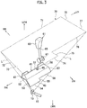
Fig. 3] Fig. 3 is a perspective view of an electromagnetic wave radiating portion, a shielding plate, an automatic transmission, and a shield region. - [
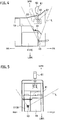
Fig. 4] Fig. 4 is a side view ofFig. 2 as viewed from the side of the vehicle. - [
Fig. 5] Fig. 5 is a front view ofFig. 2 as viewed from the front of the vehicle. - [
Fig. 6] Fig. 6 is a side view showing a state in which drops of water fall into the console through a lever hole provided on the console. - An embodiment of the present invention will be described below. As used herein, the sign "FR" denotes the front side of a vehicle, the sign "RR" denotes the back side of the vehicle, the sign "RH" denotes the right side in the vehicle width direction, the sign "LH" denotes the left side in the vehicle width direction, the sign "UPR" denotes the upper side of the vehicle, and the sign "LWR" denotes the lower side of the vehicle.
- As shown in
Fig. 1 , a driver'sseat 3 is located on the right and apassenger seat 5 is located on the left on the front side of a passenger compartment of a vehicle 1. The driver'sseat 3 includes aseat cushion 3a and aseat back 3b, and thepassenger seat 5 includes aseat cushion 5a and aseat back 5b. Aconsole 7 is placed between the driver'sseat 3 and thepassenger seat 5. - As shown in
Fig. 1 andFig. 2 , theconsole 7 is formed of resin into a U-shape in cross section open on the bottom side as viewed from the front side of the vehicle. Theconsole 7 is an integrated member including a pair of right andleft side walls upper wall 7b elongated in the vehicle width direction so as to connect upper edges of the pair of right andleft side walls upper wall 7b of theconsole 7 is provided with alever hole 7c having a rectangular shape elongated in the vehicle front-rear direction. - The
console 7 houses a DC/DC converter 9 (electrical instrument) and abattery 19 placed on the floor in theconsole 7. In particular, the DC/DC converter 9 is installed on the floor via thebattery 19. - The
battery 19 is provided with arecessed portion 21 at a corner on the front right side, and the DC/DC converter 9 is located at therecessed portion 21. The upper surface of thebattery 19 has three steps in the vertical direction. More particularly, the upper surface of thebattery 19 has a firstupper surface 23 located on the lowermost side, a secondupper surface 25 located higher than the firstupper surface 23, and a thirdupper surface 27 located higher than the secondupper surface 25. - A
casing 11 of the DC/DC converter 9 (electrical instrument) has a box shape provided with anopening 13 at a lower portion on afront surface 11 a, and acable 15 is inserted into theopening 13. More particularly, aseal member 17 formed of rubber or resin is fitted into theopening 13, and thecable 15 is inserted and fixed to theseal member 17. The DC/DC converter 9 includes a plurality of semiconductor devices (not shown), and turns on/off the plurality of semiconductor devices at short intervals, so as to radiate electromagnetic waves. The electromagnetic waves are radiated (transmitted) to the outside of thecasing 11 through theopening 13. In this specification, theopening 13 of thecasing 11 serves as an electromagnetic wave radiating portion. Thefront surface 11 a of thecasing 11 of the DC/DC converter 9 is arranged on the same plane as afront surface 31 of thebattery 19 located on the lower side of the firstupper surface 23. Aside surface 11b of thecasing 11 is arranged at substantially the same position in the vehicle width direction as aside surface 33 of thebattery 19. Anupper surface 11c of thecasing 11 is located lower than the firstupper surface 23 of thebattery 19. - As shown in
Fig. 2 andFig. 3 , a metal shielding plate 41 (shielding member) is closely fixed onto the firstupper surface 23 of thebattery 19. Theshielding plate 41 is made of metal and connected to a body ground as described below, so as to function as a shield against electromagnetic waves. Theshielding plate 41 is an integrated member including abody 43 elongated in the front-rear direction and the right-left direction, an extendingpart 45 bent and extending downward from the front edge of thebody 43, and a pair offlanges 47 bent and extending upward on both sides at the rear edge of thebody 43. The extendingpart 45 has a long part extending in the front-rear direction on the right side and a short part extending in the front-rear direction on the left side. Theshielding plate 41 is fastened onto the firstupper surface 23 of thebattery 19 with abolt 49, so that theshielding plate 41 is grounded to thebattery 19. As shown inFig. 3 , theshielding plate 41 has a circumferential edge including afirst edge 51 located at the rear edge of thebody 43, asecond edge 52 located at the right edge of thebody 43, athird edge 53 located at the right edge of the extendingpart 45, afourth edge 54 located at the front edge on the right side of the extendingpart 45, afifth edge 55 extending backward from the left corner of thefourth edge 54, asixth edge 56 located at the front edge on the left side of the extendingpart 45, aseventh edge 57 located at the left edge on the left side of the extendingpart 45, and aneighth edge 58 located at the left edge of thebody 43. - As shown in
Fig. 3 to Fig. 5 , theopening 13 of thecasing 11 serving as an electromagnetic wave radiating portion is provided immediately below theshielding plate 41 on the right side of the extendingpart 45. Namely, the extendingpart 45 of theshielding plate 41 covers the upper side of the opening 13 of thecasing 11 in the vertical direction. An automatic transmission 61 (transmission) is located above theshielding plate 41. Theautomatic transmission 61 includes aknob 63 which a driver holds, a metal lever 65 (metal member) extending downward from theknob 63, asupport 67 provided at the bottom of thelever 65, and abox 69 housing and holding thesupport 67. Thelever 65 is a metal member that receives electromagnetic waves and transmits the electromagnetic waves to the passenger compartment. Although the present embodiment exemplifies theautomatic transmission 61, a manual transmission may also be applicable. - The electromagnetic waves radiated from the opening 13 (electromagnetic wave radiating portion) of the
casing 11 of the DC/DC converter 9 are not transmitted to ashield region 70 shown inFig. 3 . Theshield region 70 is defined such that theopening 13 serving as an electromagnetic wave radiating portion is connected to the circumferential edge of the shieldingplate 41 via a line L, and the line L is continuously moved along the circumferential edge of the shieldingplate 41 around the electromagnetic wave radiating portion. More particularly, the line L is continuously moved along thefirst edge 51 of the shieldingplate 41 to define afirst edge 71 of theshield region 70, and further moved along thesecond edge 52 to define asecond edge 72 of theshield region 70. Similarly, the line L is moved along thethird edge 53 to define athird edge 73, moved along thefourth edge 54 to define afourth edge 74, and moved along thefifth edge 55 to define afifth edge 75. Further, the Line L is moved along thesixth edge 56 to define asixth edge 76, moved along theseventh edge 57 to define aseventh edge 77, and moved along theeighth edge 58 to define aneighth edge 78. The circumferential edge of theshield region 70 at an intermediate portion in the vertical direction is thus defined by thefirst edge 71 to theeighth edge 78. More particularly, the lowermost portion of theshield region 70 is located at the same level as the height of the shieldingplate 41, the intermediate portion of theshield region 70 is defined by thefirst edge 71 to theeighth edge 78, and the sides of theshield region 70 are defined by the continuous movement of the line L. The uppermost portion of theshield region 70 is not defined because the electromagnetic waves are transmitted radially. - The
automatic transmission 61 is arranged above the shieldingplate 41 in theshield region 70. - As shown in
Fig. 6 , the shieldingplate 41 also functions to protect theopening 13 of thecasing 11 of the DC/DC converter 9 from drops ofwater 80. As described above with reference toFig. 2 , thelever hole 7c is formed on theupper wall 7b of theconsole 7. A cup holder (not shown) is provided at theupper wall 7b of theconsole 7. When a drink cup placed in the cup holder leans and thedrops 80 of a drink enter theconsole 7 through thelever hole 7c, thedrops 80 come into contact with the shieldingplate 41 and fall downward from afront edge 45a of the extendingpart 45 toward a floor FL, as indicated by the dash-dotted line inFig. 6 . Accordingly, the periphery of theopening 13 of thecasing 11 can be prevented from being wetted. - Although the present embodiment exemplifies the DC/
DC converter 9 as an electrical instrument, a DC/AC converter may be used instead. - The advantageous effects of the embodiment of the present invention are described below.
- (1) The embodiment of the present invention relates to an electromagnetic wave shielding structure of the
console 7 installed in the passenger compartment of the vehicle 1. - The electromagnetic wave shielding structure includes the DC/DC converter 9 (electrical instrument) installed in the
console 7 from which electromagnetic waves are radiated, the automatic transmission 61 (transmission) including the lever 65 (metal member) that receives the electromagnetic waves and transmits the electromagnetic waves to the passenger compartment and separated by a distance from the DC/DC converter 9, and the shielding plate 41 (shielding member) located between the DC/DC converter 9 and theautomatic transmission 61 to function as a shield against the electromagnetic waves radiated from the DC/DC converter 9. Theautomatic transmission 61 is located in theshield region 70 defined such that the opening 13 (electromagnetic wave radiating portion) provided at the DC/DC converter 9 from which the electromagnetic waves are radiated is connected to the circumferential edge of the shieldingplate 41 via the line L, and the line L is continuously moved along the circumferential edge of the shieldingplate 41 around theopening 13. - The electromagnetic waves are radially transmitted from the electromagnetic wave radiating portion of the electrical instrument. If the shielding
plate 41 is not provided, the electromagnetic waves radiated from the electromagnetic wave radiating portion of the DC/DC converter 9 are transmitted to the passenger compartment via thelever 65 of theautomatic transmission 61, which may cause faults such as noise of a radio. - The present embodiment thus provides the shielding
plate 41 between the DC/DC converter 9 and theautomatic transmission 61. Further, theautomatic transmission 61 is located in theshield region 70 defined such that the line L, which connects the electromagnetic wave radiating portion and the circumferential edge of the shieldingplate 41, is continuously moved along the circumferential edge of the shieldingplate 41. Since theshield region 70 is shielded from the electromagnetic waves, the radiation of the electromagnetic waves via theautomatic transmission 61 toward the passenger compartment can be prevented efficiently when theautomatic transmission 61 is located in theshield region 70. Accordingly, the possibility of arrangement of the electrical instrument radiating the electromagnetic waves can be expanded. - (2) The shielding member is formed of the shielding
plate 41, the DC/DC converter 9 is installed at the bottom in theconsole 7, theautomatic transmission 61 is located above the DC/DC converter 9, the shieldingplate 41 is placed between the DC/DC converter 9 and theautomatic transmission 61 in the vertical direction, the shieldingplate 41 includes thebody 43 elongated in the front-rear direction and the right-left direction and the extendingpart 45 bent and extending obliquely downward at the edge of thebody 43, and the extendingpart 45 covers theopening 13 of the DC/DC converter 9. - The extending
part 45 of the shieldingplate 41 covers theopening 13 of the DC/DC converter 9. Thus, the shieldingplate 41 can more efficiently shield theautomatic transmission 61 against the electromagnetic waves radiated from theopening 13 serving as an electromagnetic wave radiating portion. - The extending
part 45 of the shieldingplate 41 is bent and extends obliquely downward. The drops 80 falling down from the upper portion of theconsole 7 can efficiently be drained downward along the shieldingplate 41. The shieldingplate 41 can thus efficiently protect theopening 13 of the DC/DC converter 9 from thedrops 80. - (3) The shielding
plate 41 is arranged immediately above the opening 13 (electromagnetic radiating portion) of the DC/DC converter 9 so as to cover theopening 13. - The shielding
plate 41 thus accurately shields theautomatic transmission 61 against the electromagnetic waves radiated from theopening 13. - The shielding
plate 41 can also protect theopening 13 of the DC/DC converter 9 from thedrops 80 falling down from the upper side of theconsole 7. - (4) The shielding plate 41 (shielding member) is connected to a body ground.
- The shielding
plate 41, which is required to be grounded, is not necessarily provided with a dedicated ground cable because the shieldingplate 41 is connected to the body ground. Accordingly, the ground can be implemented at low cost, and the working process of grounding can be simplified. -
- 7
- console
- 9
- dc/dc converter (electrical instrument)
- 13
- opening (electromagnetic wave radiating portion)
- 41
- shielding plate (shielding member)
- 43
- body
- 45
- extending part
- 51
- first edge (circumferential edge)
- 52
- second edge (circumferential edge)
- 53
- third edge (circumferential edge)
- 54
- fourth edge (circumferential edge)
- 55
- fifth edge (circumferential edge)
- 56
- sixth edge (circumferential edge)
- 57
- seventh edge (circumferential edge)
- 58
- eight edge (circumferential edge)
- 61
- automatic transmission (transmission)
- 65
- lever (metal member)
- 70
- shield region
Claims (4)
- An electromagnetic wave shielding structure of a console installed in a passenger compartment of a vehicle, the electromagnetic wave shielding structure comprising:an electrical instrument installed in the console from which electromagnetic waves are radiated;a transmission including a metal member that receives the electromagnetic waves and transmits the electromagnetic waves to the passenger compartment and separated by a distance from the electrical instrument; anda shielding member located between the electrical instrument and the transmission to function as a shield against the electromagnetic waves radiated from the electrical instrument,the transmission being located in a shield region defined such that an electromagnetic wave radiating portion provided at the electrical instrument from which the electromagnetic waves are radiated is connected to a circumferential edge of the shielding member via a straight line, and the line is continuously moved along the circumferential edge of the shielding member around the electromagnetic wave radiating portion.
- The electromagnetic wave shielding structure of the console installed in the passenger compartment of the vehicle according to claim 1, wherein:the shielding member is formed of a shielding plate;the electrical instrument is installed at a bottom in the console, the transmission is provided above the electrical instrument, and the shielding plate is located between the electrical instrument and the transmission in a vertical direction;the shielding plate includes a body elongated in a front-rear direction and a right-left direction, and an extending part bent and extending obliquely downward at an edge of the body; andthe extending part is arranged to cover the electromagnetic wave radiating portion of the electrical instrument.
- The electromagnetic wave shielding structure of the console installed in the passenger compartment of the vehicle according to claim 2, wherein the shielding plate is located immediately above the electromagnetic wave radiating portion of the electrical instrument so as to cover the electromagnetic wave radiating portion.
- The electromagnetic wave shielding structure of the console installed in the passenger compartment of the vehicle according to any one of claims 1 to 3, wherein the shielding member is connected to a body ground.
Applications Claiming Priority (1)
| Application Number | Priority Date | Filing Date | Title |
|---|---|---|---|
| PCT/JP2014/071310 WO2016024331A1 (en) | 2014-08-12 | 2014-08-12 | Electromagnetic wave-blocking structure in vehicle console box |
Publications (3)
| Publication Number | Publication Date |
|---|---|
| EP3181405A1 true EP3181405A1 (en) | 2017-06-21 |
| EP3181405A4 EP3181405A4 (en) | 2018-01-10 |
| EP3181405B1 EP3181405B1 (en) | 2018-09-05 |
Family
ID=55303975
Family Applications (1)
| Application Number | Title | Priority Date | Filing Date |
|---|---|---|---|
| EP14899674.7A Not-in-force EP3181405B1 (en) | 2014-08-12 | 2014-08-12 | Electromagnetic wave-blocking structure in vehicle console box |
Country Status (7)
| Country | Link |
|---|---|
| US (1) | US9902332B2 (en) |
| EP (1) | EP3181405B1 (en) |
| JP (1) | JP6288278B2 (en) |
| CN (1) | CN106573579B (en) |
| MX (1) | MX354709B (en) |
| RU (1) | RU2636637C1 (en) |
| WO (1) | WO2016024331A1 (en) |
Families Citing this family (3)
| Publication number | Priority date | Publication date | Assignee | Title |
|---|---|---|---|---|
| KR20210104842A (en) * | 2018-12-17 | 2021-08-25 | 노틸러스 디펜스 엘엘씨 | Functional braided composite yarn |
| JP7302457B2 (en) | 2019-11-27 | 2023-07-04 | トヨタ自動車株式会社 | Magnetic field shield structure |
| RU2742585C1 (en) * | 2020-09-23 | 2021-02-08 | Акционерное общество «АВТОВАЗ» | Motor vehicle equipped with an onboard radio-technical complex |
Family Cites Families (13)
| Publication number | Priority date | Publication date | Assignee | Title |
|---|---|---|---|---|
| JPH0528966U (en) * | 1991-09-27 | 1993-04-16 | 愛知電機株式会社 | Rotation detector protection device |
| JPH06199183A (en) * | 1992-12-28 | 1994-07-19 | Honda Motor Co Ltd | Console box for electric vehicle |
| FR2815778B1 (en) * | 2000-10-23 | 2002-12-06 | Alstom | PROTECTION DEVICE OF AN ELECTRICAL CONNECTOR FOR A PRINTED CIRCUIT PLATE AGAINST ELECTROMAGNETIC DISTURBANCES |
| JP2002178313A (en) * | 2000-12-14 | 2002-06-26 | Shinwa Mokko Kk | Board for adsorbing odor and shielding electromagnetic wave |
| JP4626476B2 (en) * | 2005-10-14 | 2011-02-09 | トヨタ自動車株式会社 | Storage device cooling structure |
| JP4390802B2 (en) * | 2006-12-15 | 2009-12-24 | トヨタ自動車株式会社 | In-vehicle battery cooling structure |
| WO2008086089A1 (en) | 2007-01-04 | 2008-07-17 | Johnson Controls Technology Company | Integrated soft center floor console |
| JP2011105270A (en) | 2009-11-20 | 2011-06-02 | Toyota Motor Corp | Vehicle |
| KR20130072608A (en) * | 2011-12-22 | 2013-07-02 | 삼성전자주식회사 | Display apparatus |
| CN202738373U (en) * | 2012-01-18 | 2013-02-13 | 中怡(苏州)科技有限公司 | Electronic device with radiating electromagnetic shielding cover |
| DE102012010404B4 (en) | 2012-05-25 | 2018-10-31 | Audi Ag | Arrangement for receiving at least one small electronic device |
| JP2013258642A (en) * | 2012-06-14 | 2013-12-26 | Toshiba Corp | Television receiver and electronic apparatus |
| KR20140006392A (en) * | 2012-07-05 | 2014-01-16 | 엘에스산전 주식회사 | Electronic component box for vehicle |
-
2014
- 2014-08-12 JP JP2016542464A patent/JP6288278B2/en not_active Expired - Fee Related
- 2014-08-12 WO PCT/JP2014/071310 patent/WO2016024331A1/en not_active Ceased
- 2014-08-12 RU RU2017107520A patent/RU2636637C1/en active
- 2014-08-12 CN CN201480081151.2A patent/CN106573579B/en not_active Expired - Fee Related
- 2014-08-12 MX MX2017001772A patent/MX354709B/en active IP Right Grant
- 2014-08-12 US US15/503,384 patent/US9902332B2/en not_active Expired - Fee Related
- 2014-08-12 EP EP14899674.7A patent/EP3181405B1/en not_active Not-in-force
Also Published As
| Publication number | Publication date |
|---|---|
| US9902332B2 (en) | 2018-02-27 |
| JPWO2016024331A1 (en) | 2017-06-01 |
| MX2017001772A (en) | 2017-04-27 |
| CN106573579B (en) | 2018-01-26 |
| WO2016024331A1 (en) | 2016-02-18 |
| RU2636637C1 (en) | 2017-11-24 |
| US20170232903A1 (en) | 2017-08-17 |
| EP3181405B1 (en) | 2018-09-05 |
| CN106573579A (en) | 2017-04-19 |
| EP3181405A4 (en) | 2018-01-10 |
| JP6288278B2 (en) | 2018-03-07 |
| MX354709B (en) | 2018-03-16 |
Similar Documents
| Publication | Publication Date | Title |
|---|---|---|
| US9640873B2 (en) | Radar device for a motor vehicle, securing device for a radar apparatus and method for manufacturing an absorption element for a radar apparatus | |
| US10214168B1 (en) | Slide wiring device | |
| EP3181405B1 (en) | Electromagnetic wave-blocking structure in vehicle console box | |
| US12057625B1 (en) | Vehicle body-embedded antenna device | |
| US11605978B2 (en) | Wireless charging unit attached to a case | |
| US12009582B2 (en) | Antenna module and vehicle roof with antenna module | |
| JP2004500729A (en) | Integrated antenna means for motor vehicles including reflectors | |
| JPH06199183A (en) | Console box for electric vehicle | |
| CN111252232B (en) | Device, method and aerospace vehicle for fastening | |
| EP2311137B1 (en) | Antenna assembly for a motor vehicle | |
| CN203142794U (en) | Vehicle body reinforcing plate device | |
| JP7207282B2 (en) | Wireless power supply case | |
| US12504516B2 (en) | Laser radar mounting structure | |
| US9873398B2 (en) | Vehicle interior structure | |
| EP4032734B1 (en) | Mounting structure for electric component | |
| KR20100097704A (en) | Windshield wiper drive for a motor vehicle | |
| JP5453944B2 (en) | Object detection unit mounting structure | |
| JP2012179980A (en) | Electrical-equipment system unit arrangement structure for vehicle | |
| KR101750113B1 (en) | Radar apparatus for vehicles | |
| JP2016111825A (en) | Ground member for vehicle and automobile including the same | |
| CN110770075B (en) | Motor vehicle equipped with a central console comprising an electronic box | |
| CN217170620U (en) | Vehicle-mounted radar arrangement and installation structure and automobile | |
| KR20170006652A (en) | Side mirror antenna device for vehicle | |
| CN220518407U (en) | A post structure and vehicle | |
| CN114616719A (en) | Antenna system |
Legal Events
| Date | Code | Title | Description |
|---|---|---|---|
| STAA | Information on the status of an ep patent application or granted ep patent |
Free format text: STATUS: THE INTERNATIONAL PUBLICATION HAS BEEN MADE |
|
| PUAI | Public reference made under article 153(3) epc to a published international application that has entered the european phase |
Free format text: ORIGINAL CODE: 0009012 |
|
| STAA | Information on the status of an ep patent application or granted ep patent |
Free format text: STATUS: REQUEST FOR EXAMINATION WAS MADE |
|
| 17P | Request for examination filed |
Effective date: 20170302 |
|
| AK | Designated contracting states |
Kind code of ref document: A1 Designated state(s): AL AT BE BG CH CY CZ DE DK EE ES FI FR GB GR HR HU IE IS IT LI LT LU LV MC MK MT NL NO PL PT RO RS SE SI SK SM TR |
|
| AX | Request for extension of the european patent |
Extension state: BA ME |
|
| DAX | Request for extension of the european patent (deleted) | ||
| A4 | Supplementary search report drawn up and despatched |
Effective date: 20171208 |
|
| RIC1 | Information provided on ipc code assigned before grant |
Ipc: H05K 9/00 20060101ALI20171204BHEP Ipc: B60R 7/04 20060101AFI20171204BHEP Ipc: B62D 25/14 20060101ALI20171204BHEP Ipc: G06K 19/073 20060101ALI20171204BHEP Ipc: F16H 59/10 20060101ALI20171204BHEP Ipc: B60R 11/00 20060101ALN20171204BHEP Ipc: B60K 37/00 20060101ALI20171204BHEP |
|
| RIC1 | Information provided on ipc code assigned before grant |
Ipc: F16H 59/10 20060101ALI20180420BHEP Ipc: B60K 37/00 20060101ALI20180420BHEP Ipc: H05K 9/00 20060101ALI20180420BHEP Ipc: G06K 19/073 20060101ALI20180420BHEP Ipc: B62D 25/14 20060101ALI20180420BHEP Ipc: B60R 7/04 20060101AFI20180420BHEP Ipc: B60R 11/00 20060101ALN20180420BHEP |
|
| GRAP | Despatch of communication of intention to grant a patent |
Free format text: ORIGINAL CODE: EPIDOSNIGR1 |
|
| STAA | Information on the status of an ep patent application or granted ep patent |
Free format text: STATUS: GRANT OF PATENT IS INTENDED |
|
| RIC1 | Information provided on ipc code assigned before grant |
Ipc: H05K 9/00 20060101ALI20180515BHEP Ipc: B60K 37/00 20060101ALI20180515BHEP Ipc: B60R 7/04 20060101AFI20180515BHEP Ipc: B60R 11/00 20060101ALN20180515BHEP Ipc: F16H 59/10 20060101ALI20180515BHEP Ipc: B62D 25/14 20060101ALI20180515BHEP Ipc: G06K 19/073 20060101ALI20180515BHEP |
|
| INTG | Intention to grant announced |
Effective date: 20180605 |
|
| GRAS | Grant fee paid |
Free format text: ORIGINAL CODE: EPIDOSNIGR3 |
|
| GRAA | (expected) grant |
Free format text: ORIGINAL CODE: 0009210 |
|
| STAA | Information on the status of an ep patent application or granted ep patent |
Free format text: STATUS: THE PATENT HAS BEEN GRANTED |
|
| AK | Designated contracting states |
Kind code of ref document: B1 Designated state(s): AL AT BE BG CH CY CZ DE DK EE ES FI FR GB GR HR HU IE IS IT LI LT LU LV MC MK MT NL NO PL PT RO RS SE SI SK SM TR |
|
| REG | Reference to a national code |
Ref country code: GB Ref legal event code: FG4D |
|
| REG | Reference to a national code |
Ref country code: CH Ref legal event code: EP |
|
| REG | Reference to a national code |
Ref country code: AT Ref legal event code: REF Ref document number: 1037419 Country of ref document: AT Kind code of ref document: T Effective date: 20180915 |
|
| REG | Reference to a national code |
Ref country code: IE Ref legal event code: FG4D |
|
| REG | Reference to a national code |
Ref country code: DE Ref legal event code: R096 Ref document number: 602014032096 Country of ref document: DE |
|
| REG | Reference to a national code |
Ref country code: NL Ref legal event code: MP Effective date: 20180905 |
|
| REG | Reference to a national code |
Ref country code: LT Ref legal event code: MG4D |
|
| PG25 | Lapsed in a contracting state [announced via postgrant information from national office to epo] |
Ref country code: BG Free format text: LAPSE BECAUSE OF FAILURE TO SUBMIT A TRANSLATION OF THE DESCRIPTION OR TO PAY THE FEE WITHIN THE PRESCRIBED TIME-LIMIT Effective date: 20181205 Ref country code: LT Free format text: LAPSE BECAUSE OF FAILURE TO SUBMIT A TRANSLATION OF THE DESCRIPTION OR TO PAY THE FEE WITHIN THE PRESCRIBED TIME-LIMIT Effective date: 20180905 Ref country code: SE Free format text: LAPSE BECAUSE OF FAILURE TO SUBMIT A TRANSLATION OF THE DESCRIPTION OR TO PAY THE FEE WITHIN THE PRESCRIBED TIME-LIMIT Effective date: 20180905 Ref country code: GR Free format text: LAPSE BECAUSE OF FAILURE TO SUBMIT A TRANSLATION OF THE DESCRIPTION OR TO PAY THE FEE WITHIN THE PRESCRIBED TIME-LIMIT Effective date: 20181206 Ref country code: NO Free format text: LAPSE BECAUSE OF FAILURE TO SUBMIT A TRANSLATION OF THE DESCRIPTION OR TO PAY THE FEE WITHIN THE PRESCRIBED TIME-LIMIT Effective date: 20181205 Ref country code: RS Free format text: LAPSE BECAUSE OF FAILURE TO SUBMIT A TRANSLATION OF THE DESCRIPTION OR TO PAY THE FEE WITHIN THE PRESCRIBED TIME-LIMIT Effective date: 20180905 Ref country code: FI Free format text: LAPSE BECAUSE OF FAILURE TO SUBMIT A TRANSLATION OF THE DESCRIPTION OR TO PAY THE FEE WITHIN THE PRESCRIBED TIME-LIMIT Effective date: 20180905 |
|
| REG | Reference to a national code |
Ref country code: AT Ref legal event code: MK05 Ref document number: 1037419 Country of ref document: AT Kind code of ref document: T Effective date: 20180905 |
|
| PG25 | Lapsed in a contracting state [announced via postgrant information from national office to epo] |
Ref country code: HR Free format text: LAPSE BECAUSE OF FAILURE TO SUBMIT A TRANSLATION OF THE DESCRIPTION OR TO PAY THE FEE WITHIN THE PRESCRIBED TIME-LIMIT Effective date: 20180905 Ref country code: AL Free format text: LAPSE BECAUSE OF FAILURE TO SUBMIT A TRANSLATION OF THE DESCRIPTION OR TO PAY THE FEE WITHIN THE PRESCRIBED TIME-LIMIT Effective date: 20180905 Ref country code: LV Free format text: LAPSE BECAUSE OF FAILURE TO SUBMIT A TRANSLATION OF THE DESCRIPTION OR TO PAY THE FEE WITHIN THE PRESCRIBED TIME-LIMIT Effective date: 20180905 |
|
| PG25 | Lapsed in a contracting state [announced via postgrant information from national office to epo] |
Ref country code: CZ Free format text: LAPSE BECAUSE OF FAILURE TO SUBMIT A TRANSLATION OF THE DESCRIPTION OR TO PAY THE FEE WITHIN THE PRESCRIBED TIME-LIMIT Effective date: 20180905 Ref country code: RO Free format text: LAPSE BECAUSE OF FAILURE TO SUBMIT A TRANSLATION OF THE DESCRIPTION OR TO PAY THE FEE WITHIN THE PRESCRIBED TIME-LIMIT Effective date: 20180905 Ref country code: AT Free format text: LAPSE BECAUSE OF FAILURE TO SUBMIT A TRANSLATION OF THE DESCRIPTION OR TO PAY THE FEE WITHIN THE PRESCRIBED TIME-LIMIT Effective date: 20180905 Ref country code: IT Free format text: LAPSE BECAUSE OF FAILURE TO SUBMIT A TRANSLATION OF THE DESCRIPTION OR TO PAY THE FEE WITHIN THE PRESCRIBED TIME-LIMIT Effective date: 20180905 Ref country code: PL Free format text: LAPSE BECAUSE OF FAILURE TO SUBMIT A TRANSLATION OF THE DESCRIPTION OR TO PAY THE FEE WITHIN THE PRESCRIBED TIME-LIMIT Effective date: 20180905 Ref country code: EE Free format text: LAPSE BECAUSE OF FAILURE TO SUBMIT A TRANSLATION OF THE DESCRIPTION OR TO PAY THE FEE WITHIN THE PRESCRIBED TIME-LIMIT Effective date: 20180905 Ref country code: NL Free format text: LAPSE BECAUSE OF FAILURE TO SUBMIT A TRANSLATION OF THE DESCRIPTION OR TO PAY THE FEE WITHIN THE PRESCRIBED TIME-LIMIT Effective date: 20180905 Ref country code: ES Free format text: LAPSE BECAUSE OF FAILURE TO SUBMIT A TRANSLATION OF THE DESCRIPTION OR TO PAY THE FEE WITHIN THE PRESCRIBED TIME-LIMIT Effective date: 20180905 Ref country code: IS Free format text: LAPSE BECAUSE OF FAILURE TO SUBMIT A TRANSLATION OF THE DESCRIPTION OR TO PAY THE FEE WITHIN THE PRESCRIBED TIME-LIMIT Effective date: 20190105 |
|
| PG25 | Lapsed in a contracting state [announced via postgrant information from national office to epo] |
Ref country code: SK Free format text: LAPSE BECAUSE OF FAILURE TO SUBMIT A TRANSLATION OF THE DESCRIPTION OR TO PAY THE FEE WITHIN THE PRESCRIBED TIME-LIMIT Effective date: 20180905 Ref country code: PT Free format text: LAPSE BECAUSE OF FAILURE TO SUBMIT A TRANSLATION OF THE DESCRIPTION OR TO PAY THE FEE WITHIN THE PRESCRIBED TIME-LIMIT Effective date: 20190105 Ref country code: SM Free format text: LAPSE BECAUSE OF FAILURE TO SUBMIT A TRANSLATION OF THE DESCRIPTION OR TO PAY THE FEE WITHIN THE PRESCRIBED TIME-LIMIT Effective date: 20180905 |
|
| REG | Reference to a national code |
Ref country code: DE Ref legal event code: R097 Ref document number: 602014032096 Country of ref document: DE |
|
| PLBE | No opposition filed within time limit |
Free format text: ORIGINAL CODE: 0009261 |
|
| STAA | Information on the status of an ep patent application or granted ep patent |
Free format text: STATUS: NO OPPOSITION FILED WITHIN TIME LIMIT |
|
| PG25 | Lapsed in a contracting state [announced via postgrant information from national office to epo] |
Ref country code: DK Free format text: LAPSE BECAUSE OF FAILURE TO SUBMIT A TRANSLATION OF THE DESCRIPTION OR TO PAY THE FEE WITHIN THE PRESCRIBED TIME-LIMIT Effective date: 20180905 |
|
| 26N | No opposition filed |
Effective date: 20190606 |
|
| PG25 | Lapsed in a contracting state [announced via postgrant information from national office to epo] |
Ref country code: SI Free format text: LAPSE BECAUSE OF FAILURE TO SUBMIT A TRANSLATION OF THE DESCRIPTION OR TO PAY THE FEE WITHIN THE PRESCRIBED TIME-LIMIT Effective date: 20180905 |
|
| PG25 | Lapsed in a contracting state [announced via postgrant information from national office to epo] |
Ref country code: TR Free format text: LAPSE BECAUSE OF FAILURE TO SUBMIT A TRANSLATION OF THE DESCRIPTION OR TO PAY THE FEE WITHIN THE PRESCRIBED TIME-LIMIT Effective date: 20180905 |
|
| PG25 | Lapsed in a contracting state [announced via postgrant information from national office to epo] |
Ref country code: LI Free format text: LAPSE BECAUSE OF NON-PAYMENT OF DUE FEES Effective date: 20190831 Ref country code: CH Free format text: LAPSE BECAUSE OF NON-PAYMENT OF DUE FEES Effective date: 20190831 Ref country code: LU Free format text: LAPSE BECAUSE OF NON-PAYMENT OF DUE FEES Effective date: 20190812 Ref country code: MC Free format text: LAPSE BECAUSE OF FAILURE TO SUBMIT A TRANSLATION OF THE DESCRIPTION OR TO PAY THE FEE WITHIN THE PRESCRIBED TIME-LIMIT Effective date: 20180905 |
|
| REG | Reference to a national code |
Ref country code: BE Ref legal event code: MM Effective date: 20190831 |
|
| PG25 | Lapsed in a contracting state [announced via postgrant information from national office to epo] |
Ref country code: IE Free format text: LAPSE BECAUSE OF NON-PAYMENT OF DUE FEES Effective date: 20190812 |
|
| PG25 | Lapsed in a contracting state [announced via postgrant information from national office to epo] |
Ref country code: BE Free format text: LAPSE BECAUSE OF NON-PAYMENT OF DUE FEES Effective date: 20190831 |
|
| PG25 | Lapsed in a contracting state [announced via postgrant information from national office to epo] |
Ref country code: CY Free format text: LAPSE BECAUSE OF FAILURE TO SUBMIT A TRANSLATION OF THE DESCRIPTION OR TO PAY THE FEE WITHIN THE PRESCRIBED TIME-LIMIT Effective date: 20180905 |
|
| PG25 | Lapsed in a contracting state [announced via postgrant information from national office to epo] |
Ref country code: MT Free format text: LAPSE BECAUSE OF FAILURE TO SUBMIT A TRANSLATION OF THE DESCRIPTION OR TO PAY THE FEE WITHIN THE PRESCRIBED TIME-LIMIT Effective date: 20180905 Ref country code: HU Free format text: LAPSE BECAUSE OF FAILURE TO SUBMIT A TRANSLATION OF THE DESCRIPTION OR TO PAY THE FEE WITHIN THE PRESCRIBED TIME-LIMIT; INVALID AB INITIO Effective date: 20140812 |
|
| PG25 | Lapsed in a contracting state [announced via postgrant information from national office to epo] |
Ref country code: MK Free format text: LAPSE BECAUSE OF FAILURE TO SUBMIT A TRANSLATION OF THE DESCRIPTION OR TO PAY THE FEE WITHIN THE PRESCRIBED TIME-LIMIT Effective date: 20180905 |
|
| PGFP | Annual fee paid to national office [announced via postgrant information from national office to epo] |
Ref country code: GB Payment date: 20230720 Year of fee payment: 10 |
|
| PGFP | Annual fee paid to national office [announced via postgrant information from national office to epo] |
Ref country code: FR Payment date: 20230720 Year of fee payment: 10 Ref country code: DE Payment date: 20230720 Year of fee payment: 10 |
|
| REG | Reference to a national code |
Ref country code: DE Ref legal event code: R119 Ref document number: 602014032096 Country of ref document: DE |
|
| GBPC | Gb: european patent ceased through non-payment of renewal fee |
Effective date: 20240812 |
|
| PG25 | Lapsed in a contracting state [announced via postgrant information from national office to epo] |
Ref country code: DE Free format text: LAPSE BECAUSE OF NON-PAYMENT OF DUE FEES Effective date: 20250301 |
|
| PG25 | Lapsed in a contracting state [announced via postgrant information from national office to epo] |
Ref country code: GB Free format text: LAPSE BECAUSE OF NON-PAYMENT OF DUE FEES Effective date: 20240812 |
|
| PG25 | Lapsed in a contracting state [announced via postgrant information from national office to epo] |
Ref country code: FR Free format text: LAPSE BECAUSE OF NON-PAYMENT OF DUE FEES Effective date: 20240831 |