EP3181367A1 - Droplet discharge apparatus - Google Patents
Droplet discharge apparatus Download PDFInfo
- Publication number
- EP3181367A1 EP3181367A1 EP16204163.6A EP16204163A EP3181367A1 EP 3181367 A1 EP3181367 A1 EP 3181367A1 EP 16204163 A EP16204163 A EP 16204163A EP 3181367 A1 EP3181367 A1 EP 3181367A1
- Authority
- EP
- European Patent Office
- Prior art keywords
- drying
- section
- units
- rolled paper
- recording
- Prior art date
- Legal status (The legal status is an assumption and is not a legal conclusion. Google has not performed a legal analysis and makes no representation as to the accuracy of the status listed.)
- Granted
Links
- 238000001035 drying Methods 0.000 claims abstract description 239
- 238000007599 discharging Methods 0.000 claims abstract description 5
- 230000032258 transport Effects 0.000 description 48
- 238000004804 winding Methods 0.000 description 16
- 238000010586 diagram Methods 0.000 description 10
- 238000001514 detection method Methods 0.000 description 6
- 238000011144 upstream manufacturing Methods 0.000 description 3
- 239000004743 Polypropylene Substances 0.000 description 2
- 230000008901 benefit Effects 0.000 description 2
- 238000010438 heat treatment Methods 0.000 description 2
- 230000001678 irradiating effect Effects 0.000 description 2
- -1 polyethylene terephthalate Polymers 0.000 description 2
- 229920000139 polyethylene terephthalate Polymers 0.000 description 2
- 239000005020 polyethylene terephthalate Substances 0.000 description 2
- 229920001155 polypropylene Polymers 0.000 description 2
- 230000007723 transport mechanism Effects 0.000 description 2
- 230000004308 accommodation Effects 0.000 description 1
- 230000008859 change Effects 0.000 description 1
- 230000006870 function Effects 0.000 description 1
- 230000014509 gene expression Effects 0.000 description 1
- 230000020169 heat generation Effects 0.000 description 1
- 238000004519 manufacturing process Methods 0.000 description 1
- 230000007246 mechanism Effects 0.000 description 1
- 230000003287 optical effect Effects 0.000 description 1
Images


Classifications
-
- B—PERFORMING OPERATIONS; TRANSPORTING
- B41—PRINTING; LINING MACHINES; TYPEWRITERS; STAMPS
- B41J—TYPEWRITERS; SELECTIVE PRINTING MECHANISMS, i.e. MECHANISMS PRINTING OTHERWISE THAN FROM A FORME; CORRECTION OF TYPOGRAPHICAL ERRORS
- B41J11/00—Devices or arrangements of selective printing mechanisms, e.g. ink-jet printers or thermal printers, for supporting or handling copy material in sheet or web form
- B41J11/0015—Devices or arrangements of selective printing mechanisms, e.g. ink-jet printers or thermal printers, for supporting or handling copy material in sheet or web form for treating before, during or after printing or for uniform coating or laminating the copy material before or after printing
- B41J11/002—Curing or drying the ink on the copy materials, e.g. by heating or irradiating
- B41J11/0021—Curing or drying the ink on the copy materials, e.g. by heating or irradiating using irradiation
- B41J11/00214—Curing or drying the ink on the copy materials, e.g. by heating or irradiating using irradiation using UV radiation
-
- B—PERFORMING OPERATIONS; TRANSPORTING
- B41—PRINTING; LINING MACHINES; TYPEWRITERS; STAMPS
- B41J—TYPEWRITERS; SELECTIVE PRINTING MECHANISMS, i.e. MECHANISMS PRINTING OTHERWISE THAN FROM A FORME; CORRECTION OF TYPOGRAPHICAL ERRORS
- B41J11/00—Devices or arrangements of selective printing mechanisms, e.g. ink-jet printers or thermal printers, for supporting or handling copy material in sheet or web form
- B41J11/0015—Devices or arrangements of selective printing mechanisms, e.g. ink-jet printers or thermal printers, for supporting or handling copy material in sheet or web form for treating before, during or after printing or for uniform coating or laminating the copy material before or after printing
- B41J11/002—Curing or drying the ink on the copy materials, e.g. by heating or irradiating
- B41J11/0021—Curing or drying the ink on the copy materials, e.g. by heating or irradiating using irradiation
- B41J11/00216—Curing or drying the ink on the copy materials, e.g. by heating or irradiating using irradiation using infrared [IR] radiation or microwaves
-
- B—PERFORMING OPERATIONS; TRANSPORTING
- B41—PRINTING; LINING MACHINES; TYPEWRITERS; STAMPS
- B41J—TYPEWRITERS; SELECTIVE PRINTING MECHANISMS, i.e. MECHANISMS PRINTING OTHERWISE THAN FROM A FORME; CORRECTION OF TYPOGRAPHICAL ERRORS
- B41J11/00—Devices or arrangements of selective printing mechanisms, e.g. ink-jet printers or thermal printers, for supporting or handling copy material in sheet or web form
- B41J11/0015—Devices or arrangements of selective printing mechanisms, e.g. ink-jet printers or thermal printers, for supporting or handling copy material in sheet or web form for treating before, during or after printing or for uniform coating or laminating the copy material before or after printing
- B41J11/002—Curing or drying the ink on the copy materials, e.g. by heating or irradiating
- B41J11/0022—Curing or drying the ink on the copy materials, e.g. by heating or irradiating using convection means, e.g. by using a fan for blowing or sucking air
-
- B—PERFORMING OPERATIONS; TRANSPORTING
- B41—PRINTING; LINING MACHINES; TYPEWRITERS; STAMPS
- B41J—TYPEWRITERS; SELECTIVE PRINTING MECHANISMS, i.e. MECHANISMS PRINTING OTHERWISE THAN FROM A FORME; CORRECTION OF TYPOGRAPHICAL ERRORS
- B41J2/00—Typewriters or selective printing mechanisms characterised by the printing or marking process for which they are designed
- B41J2/005—Typewriters or selective printing mechanisms characterised by the printing or marking process for which they are designed characterised by bringing liquid or particles selectively into contact with a printing material
- B41J2/01—Ink jet
Definitions
- the present invention relates to a droplet discharge apparatus provided with a drying function of a recording medium.
- a droplet discharge apparatus for example, an ink jet printer
- a recording section for example, an ink jet head
- a drying section for example, a heater
- JP-A-11-115175 discloses an ink jet printer that includes a plurality of heaters that are divided in the direction perpendicular to the transport direction of the recording medium, and is provided with a control mechanism that turns on or off the plurality of heaters in accordance with the state of the printing (recording).
- An advantage of some aspects of the invention is that it is possible to realize the following applications or modes.
- a droplet discharge apparatus including a recording section that performs recording by discharging droplets onto a recording medium; and a drying section including a plurality of drying units that performs drying of the recording medium to which the droplets have been discharged, wherein the drying units are movably disposed in a predetermined drying area in which the drying of the recording medium is performed.
- a plurality of drying units are movably disposed in a predetermined drying area in which the recording medium is subjected to drying, and thus it is possible to easily dispose the drying units at more suitable positions in accordance with the position of the recording medium. As a result, it is possible to efficiently use the drying units.
- the droplet discharge apparatus may further include a control section that individually drive controls the plurality of drying units.
- the droplet discharge apparatus includes a control section that individually drive controls the plurality of drying units, and thus it is possible to effectively drive the drying units that are disposed at more suitable positions in accordance with the position of the recording medium.
- the droplet discharge apparatus may further include a transport section that transports the recording medium in a first direction in the drying area, wherein the drying units are movably disposed in a second direction that intersects the first direction.
- the drying units are movably disposed in the second direction that intersects the first direction in which the recording medium is transported in the drying area, and thus it is possible to move the drying units in accordance with the position of the recording medium in the second direction, which is transported in the drying area, or in accordance with the position of the drying in the second direction with respect to the recording medium that is transported in the drying area. As a result, it is possible to perform the drying of the recording medium more effectively and efficiently.
- the droplet discharge apparatus may further include a plurality of guiding members that guide the drying units to move across both ends of the drying area in the second direction.
- a plurality of guiding members that guide the drying units to move across both ends of the drying area in the second direction are provided, and thus it is possible to dispose the plurality of drying units in order in the first direction for the recording medium that is transported in the first direction in the drying area. As a result, it is possible to perform the drying more effectively and efficiently.
- the plurality of drying units may include drying units having different lengths in the second direction in which the individual drying units perform drying.
- the plurality of drying units include drying units having different lengths in the second direction in which the individual drying units perform drying, and thus when the plurality of drying units are disposed in order in the first direction for the recording medium that is transported in the first direction in the drying area, it is possible to dispose the individual drying units such that the outer edges of the areas that are subjected to the drying do not overlap each other. As a result, it is possible to prevent the occurrence of drying unevenness.
- the transport section may transport a plurality of the recording media that are arranged in the second direction in parallel with the first direction.
- the transport section transports a plurality of the recording media that are arranged in the second direction in parallel with the first direction.
- the plurality of drying units are movably disposed in the second direction that intersects the first direction, and thus it is possible to dispose the drying units in accordance with the positions of the individual recording media in the second direction.
- the droplet discharge apparatus may further include a drive section that moves the drying units in the second direction, wherein the control section controls the drive section on the basis of positional information of the recording medium in the second direction in the drying area.
- the droplet discharge apparatus may include a drive section that moves the drying units in the second direction, and the control section controls the drying units on the basis of the positional information of the recording medium in the second direction in the drying area. Accordingly, it is possible to automatically dispose the drying units at suitable positions even if the position of the recording medium is changed.
- Fig. 1 is a side view schematically illustrating a printer 100 as a "droplet discharge apparatus" according to a first embodiment.
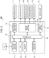
- Fig. 2 is a block diagram of the printer 100.
- the printer 100 is a multi-roll ink jet printer in which a plurality of rolls of rolled paper 1 that is supplied in a roll state as a "recording medium” are allowed to be set in parallel, and images are allowed to be recorded (printed) on the plurality of rolls of the rolled paper 1.
- the printer 100 includes a recording section 10, a transport section 20, a supply section 30, a winding section 40, a transport path 50, a drying section 60, a control section 70, and the like.
- the rolled paper 1 is supplied from the supply section 30, is transported along the transport path 50 via the recording section 10 in accordance with recording, and is stored in the winding section 40.
- the rolled paper 1 it is possible to use, for example, high quality paper, cast paper, art paper, coated paper, synthetic paper. Also, it is possible to use a film, or the like that is made from polyethylene terephthalate (PET), polypropylene (PP), or the like.
- the recording section 10 includes a recording head 11, a carriage 12, a guide shaft 13, and the like.
- the recording head 11 is an ink jet head provided with a plurality of nozzles that discharge ink droplets as "droplets".
- the guide shaft 13 extends in the scanning direction (the X-axis direction in Fig. 1 and is the same direction as the "second direction” of the invention), which intersects the transport direction as the "first direction” in which the rolled paper 1 moves.
- the carriage 12 is mounted with the recording head 11, and performs reciprocating movement (scanning movement) along the guide shaft 13 by a carriage motor 14 (refer to Fig. 2 ) under the drive control of the control section 70.
- the control section 70 alternately repeats a discharge operation of ink droplets from the recording head 11 while moving the carriage 12 in the scanning direction, and a transport operation by the transport section 20 of moving the rolled paper 1 in the transport direction so as to form (record) a desired image on the rolled paper 1.
- the recording section 10 has a configuration including a serial head that performs reciprocating movement in the scanning direction.
- the recording section 10 may have a configuration including a line head in which ink discharging nozzles are arranged in the direction perpendicular to the transport direction over the range in which the rolled paper 1 can be set.
- the droplet discharge apparatus may be a droplet discharge apparatus including a recording section other than a so-called an ink jet recording head.
- the transport section 20 is a transport mechanism that moves the rolled paper 1 in the transport direction in the recording section 10, and includes a drive roller 21 with a nip roller, and the like.
- the rolled paper 1 is transported by driving the drive roller 21 in a state in which the rolled paper 1 is sandwiched between the drive roller 21 and the nip roller.
- the drive roller 21 is driven by a transport motor 22 (refer to Fig. 2 ) under the drive control of the control section 70.
- the transport section 20 is not limited to be configured by these rollers, and may be configured by a transport belt, or the like, for example.
- the supply section 30 is an accommodation section that accommodates the rolled paper 1 before being subjected to recording.
- the supply section 30 is located at the upstream side of the recording section 10 in the transport path 50, and includes a feeding shaft 31, and the like.
- the feeding shaft 31 is rotated by a feeding motor 32 (refer to Fig. 2 ) under the drive control of the control section 70, and feeds the rolled paper 1, which has been set, to the recording section 10 disposed at the downstream side of the supply section 30.
- the winding section 40 is a storage section that winds the rolled paper 1 on which the recording has completed and stores the rolled paper 1 in a roll state.
- the winding section 40 is located at the downstream side of the recording section 10 in the transport path 50, and includes a winding shaft 41, and the like.
- the winding shaft 41 is a rotational axis that is rotated by a winding motor 42 (refer to Fig. 2 ) under the drive control of the control section 70, and the rolled paper 1, which has been sent via the recording section 10, is wound around the rotational axis as an axis center.
- the transport path 50 is a transport path on which the rolled paper 1 is transported from the supply section 30 to the winding section 40 via the recording section 10.
- the transport path 50 includes a medium support section 51 including a platen that supports the rolled paper 1 in the recording area of the recording section 10, a rotational bar member 52, and the like.
- the rotational bar member 52 extends over the range in the width direction of the rolled paper 1 in which the rolled paper 1 can be set between the downstream side end of the transport path included in the medium support section 51 and the winding section 40.
- the rotational axis of the rotational bar member 52 is fixedly supported by the main body of the printer 100.
- the rotational bar member 52 is rotated with the movement of the rolled paper 1 which is in contact with the rotational bar member 52 so as to support movement of the rolled paper 1.
- the drying section 60 is a part that performs drying of the rolled paper 1 on which recording has been carried out (that is to say, ink droplets have been impacted), and is located at the downstream side of the recording section 10 and at the upstream side of the winding section 40 in the transport path 50.
- the drying section 60 includes a plurality of drying units 61.
- the drying units 61 include heaters disposed at the positions opposed to the surface, on which droplets have been impacted, of the rolled paper 1 that are transported while being supported by the medium support section 51.
- the control section 70 includes an input and output section 71, a CPU 72, a memory 73, a detection section 74, a head drive section 75, a motor drive section 76, a drying unit drive section 77, a system bus 78, and the like, and performs centralized control of the entire printer 100.
- the input and output section 71 sends and receives data between an external device (for example, personal computer PC) and the printer 100.
- the CPU 72 is a processor that performs control of the entire printer 100, and is connected to the input and output section 71, the memory 73, the detection section 74, the head drive section 75, the motor drive section 76, and the drying unit drive section 77 via the system bus 78.
- the memory 73 is an area in which the programs executed by the CPU 72 are stored, and the necessary information is recorded, and constituted by a memory element, such as a RAM, a ROM, a flash memory, or the like.
- the CPU 72 controls the head drive section 75, the motor drive section 76, and the drying unit drive section 77 in accordance with the program stored in the memory 73 and a recording job (print instruction) received from the external device.
- the detection section 74 includes a plurality of detection device groups (for example, a linear encoder, a rotary encoder, an optical sensor, a temperature sensor, and the like) that are disposed at predetermined places of the inside of the printer 100, such as the recording section 10, the transport section 20, the supply section 30, the winding section 40, the transport path 50, the drying section 60, and the like, and detects (monitors) the operating state of the inside of the printer 100, and outputs the detection result to the control section 70.
- detection device groups for example, a linear encoder, a rotary encoder, an optical sensor, a temperature sensor, and the like
- the detection section 74 monitors the position of the carriage 12 that performs scan movement along the guide shaft 13, the setting position of the rolled paper 1 in the width direction of in the transport path 50, the transport state (whether or not the medium is jammed, or the like), whether there is the remaining amount of rolled paper 1, whether there is the remaining amount of ink in the recording section 10, and the like.
- Fig. 3 is a schematic diagram for explaining the disposition and the configuration of the drying section 60, which characterizes this embodiment.
- Fig. 3 illustrates a state in which a path on which the rolled paper 1 is transported from the supply section 30 to the winding section 40 is schematically expanded in the plan view, and two rolls of the rolled paper 1, that is to say, a rolled paper 1A and a rolled paper 1B are set in the transport path 50.
- the recording section 10 in order for the recording head 11 to record both on the rolled paper 1A and the rolled paper 1B, the recording section 10 performs scan movement over the individual printing areas of the rolled paper 1A and the rolled paper 1B in the scanning direction. Also, the transport of the rolled paper 1A and the rolled paper 1B is carried out by the transport section 20, the supply section 30, and the winding section 40 in common (at the same time).
- the area (hereinafter referred to as a drying area 60A) in which drying is performed by the drying section 60 of the rolled paper 1 (the rolled paper 1A and the rolled paper 1B) is a predetermined area that is subjected to effective drying by the heaters included in the drying units 61 in the rolled paper 1 that is supported by the medium support section 51 at the position on the downstream side of the recording section 10 and on the upstream side of the winding section 40.
- the "transport section” according to the invention is a transport mechanism that transports the rolled paper 1 in the transport direction as the "first direction" in the drying area 60A in this embodiment, and includes the transport section 20, the supply section 30, the winding section 40, and the transport path 50.
- the "transport section” constituted by those sections transports a plurality of rolls of rolled paper 1 that are arranged in the "second direction "(the direction intersecting the first direction, and the X-axis direction illustrated in Fig. 1 ) and in parallel with the transport direction (the first direction).
- the drying section 60 includes a plurality of (four in the example illustrated in Fig. 3 ) drying units 61 and a plurality of (two pairs and four lines in the example in Fig. 3 ) slide rails 62 as a plurality of "guiding members" that guide the drying unit 61 over both ends of the drying area 60A in the second direction, or the like.
- the slide rails 62 extend in the second direction and both ends thereof are fixed to the main body of the printer 100 (omitted in Fig. 3 ), and support the drying units 61 in a slidably contact state. It is possible to set a drying unit 61 at a suitable position by manually sliding the drying unit 61 so as to match the position of the rolled paper 1 to be subjected to drying in advance.
- Each of the drying units 61 includes a heater using a heating resistor, and a reflective plate (omitted in Fig. 3 ) for effectively irradiating infrared rays emitted by the heater on the rolled paper 1, and the like. Also, for the drying units 61, two kinds of units, namely a drying unit 61A and a drying unit 61B that have different width (length) of the heater in the second direction, and thus have different length (hereinafter referred to as an effective drying width) of performing drying in the second direction to each other are used.
- Each of the drying units 61 (the drying unit 61A and the drying unit 61B) is subjected to individual drive control of the control section 70. That is to say, the control section 70 controls the drying unit drive section 77 (refer to Fig. 2 ) so as to make it possible to turn on and off of each individual drying unit 61 and to perform control of the amount of heat generation in the case of turning on.
- An effective drying width w1 of each drying unit 61A is longer than an effective drying width w2 of each drying unit 61B. If the effective drying width w2 of the drying unit 61B is used alone, the rolled paper 1 having the minimum width that is handled by the printer 100 is supported. If the effective drying width w1 of the drying unit 61A is used alone, the rolled paper 1 having the width longer than the effective drying width w2 of the drying unit 61B and up to the effective drying width w1 of the drying unit 61A is supported. As illustrated in Fig. 3 , two pairs, each of which includes the drying unit 61A and the drying unit 61B, are disposed movably in the second direction by the slide rails 62.
- the drying unit 61B is disposed on the +X side of the near side to the recording section 10 of the slide rails 62, and the drying unit 61A is disposed on the -X side thereof.
- the drying unit 61A is disposed on the +X side of the near side to the winding section 40 of the slide rails 62, and the drying unit 61B is disposed on the -X side thereof.
- Fig. 4 is a schematic diagram illustrating an example of the disposition of the drying units 61.
- the drying units 61 (the drying units 61A and the drying units 61B) may be disposed as illustrated in Fig. 4 , for example. That is to say, when one roll of the rolled paper 1 is set in the printer 100, if the width of the rolled paper 1 is longer than the effective drying width w1 of the drying unit 61A, and is shorter than the sum of the effective drying width w1 of the drying unit 61A and the effective drying width w2 of the drying unit 61B, the drying unit 61A and the drying unit 61B on the same one of the slide rails 62 may be brought close to each other and disposed on the rolled paper 1.
- the drying unit 61A on another one of the slide rails 62 which has the overlapping position with this boundary in the transport direction (the first direction), expedites the drying, and thus the occurrence of drying unevenness is suppressed by the overlap with the individual boundaries.
- the plurality of drying units 61 are movably disposed in the predetermined drying area 60A in which drying is performed on the rolled paper 1, and thus it is possible to easily dispose the drying units 61 at more suitable positions in accordance with the position of the rolled paper 1. As a result, it is possible to utilize the drying units 61 more efficiently.
- control section 70 that individually drive controls the plurality of drying units 61 is provided, and thus it is possible to more effectively drive the drying units 61 that are disposed at more suitable positions in accordance with the positions of the rolled paper 1.
- the drying units 61 are movably disposed in the second direction that intersects the first direction (the transport direction) in which the rolled paper 1 is transported in the drying area 60A, and thus it is possible to move the drying units 61 in accordance with the position of the rolled paper 1 transported in the drying area 60A in the second direction or in accordance with the position of the drying on the rolled paper 1 transported in the drying area 60A in the second direction. As a result, it is possible to perform drying of the rolled paper 1 more effectively and efficiently.
- a plurality of pairs of slide rails 62 that guide the drying units 61 over both ends of the drying area 60A in the second direction are provided, and thus it is possible to arrange a plurality of drying units 61 in the first direction for the rolled paper 1 that is transported in the first direction (the transport direction) in the drying area 60A. As a result, it is possible to perform drying more effectively and efficiently.
- a plurality of drying units 61 include the drying units 61 having different lengths in the second direction in which individual drying units 61 perform drying, and thus if a plurality of drying units 61 are disposed in order in the first direction for the rolled paper 1 that is transported in the first direction in the drying area 60A, it is possible to dispose the individual drying units 61 such that the outer edges of the drying areas do not overlap with each other. As a result, it is possible to prevent the occurrence of drying unevenness.
- the transport section it is possible for the transport section to transport a plurality of rolls of rolled paper 1 that are arranged in the second direction in parallel with the first direction.
- a plurality of drying units 61 are movably disposed in the second direction that intersects the first direction, and thus it is possible to dispose the drying units 61 to match the positions of the individual rolls of the rolled paper 1 in the second direction.
- the invention is not limited to the above-described embodiment, and it is possible to make various changes and improvements of the above-described embodiment, and the like. A description will be given below of a variation.
- a same reference symbol is used for a same component as that of the embodiment described above, and a duplicated description will be omitted.
- Fig. 5 is a schematic diagram illustrating an example of a configuration of the drying section 60 according to a first variation.
- two drying units 61 (the drying unit 61A and the drying unit 61B) are movably disposed on one pair of slide rails 62.
- the invention is not limited to this configuration.
- only one of the drying units 61 may be movably disposed on one pair of slide rails 62, or three or more drying units 61 may be movably disposed.
- two pairs of slide rails 62 are provided in the configuration.
- the invention is not limited to this configuration, and a larger number of pairs of slide rails 62 may be provided.
- the drying section 60 is provided with six pairs of slide rails 62. Only one drying unit 61C is movably disposed on each pair of slide rails 62. With such a configuration, it is possible to utilize six drying units 61C, and thus for example, an effective drying width w3 of the drying units 61C may be shorter than the effective drying width w2 of the drying units 61B.
- Fig. 6 is a schematic diagram illustrating an example of a configuration of a drying section 60 according to a second variation.
- the drying units 61 are set to suitable positions by manually sliding the drying units 61 to match the position of the rolled paper 1 to be dried in advance.
- the invention may have a configuration provided with a drive section that moves the drying unit 61 in the second direction, and in which the control section 70 controls the drive section on the basis of the positional information of the rolled paper 1 in the second direction in the drying area 60A.
- the drying section 60 includes ball screws 62B that are rotationally driven in place of the slide rails 62, and each of the drying units 61 (the drying unit 61A and the drying unit 61B) includes a nut section 63 related to a corresponding one of the ball screws 62B that moves the related one of the drying units 61.
- the ball screws 62B are rotationally driven by the corresponding drive motors 64 as the "drive section", and the drive motors 64 are subjected to drive control individually by the control section 70.
- the control section 70 drives the individual drive motors 64 on the basis of the positional information of the rolled paper 1 in the second direction in the drying area 60A, that is to say, on the basis of the information of the size (width) of the rolled paper 1 set in the printer 100 and the set position so as to set the drying unit 61 (the drying unit 61A and the drying unit 61B) at a suitable position. In this manner, even when the position where the rolled paper 1 is set is changed, if the control section 70 recognizes the information, it is possible to automatically dispose the drying unit 61 at a suitable position.
- a description has been given that a plurality of drying units 61 (the drying unit 61A and the drying unit 61B) are movably disposed in the second direction by the slide rails 62.
- the supporting members that support both ends of the slide rails 62 may be movably configured in the transport direction (the first direction) (omitted to be illustrated in Fig. 3 ). With such a configuration, it becomes possible to move a plurality of drying units 61 in a plane including the first direction and the second direction in a predetermined drying area 60A in which the rolled paper 1 is dried. That is to say, the degree of freedom of the positions at which the drying units 61 are disposed becomes high.
- the drying units 61 include a heater using a heating resistor, a reflective plate for efficiently irradiating infrared rays emitted by the heater on the rolled paper 1, and the like.
- the invention is not limited to this.
- the invention may include a hot air blower that sends hot air, or an infrared ray lamp.
- the printer 100 the recording section 10
- the invention may include an ultraviolet ray irradiation device.
Landscapes
- Health & Medical Sciences (AREA)
- General Health & Medical Sciences (AREA)
- Toxicology (AREA)
- Ink Jet (AREA)
Abstract
Description
- The present invention relates to a droplet discharge apparatus provided with a drying function of a recording medium.
- To date, a droplet discharge apparatus (for example, an ink jet printer) provided with a recording section (for example, an ink jet head) that performs recording (printing) on a recording medium (for example, printing paper) by discharging droplets (for example, ink), and a drying section (for example, a heater) that performs drying of the discharged droplets is known. As such a droplet discharge apparatus,
JP-A-11-115175 - However, there has been a problem with the ink jet printer disclosed in
JP-A-11-115175 - An advantage of some aspects of the invention is that it is possible to realize the following applications or modes.
- According to a first application of the invention, there is provided a droplet discharge apparatus including a recording section that performs recording by discharging droplets onto a recording medium; and a drying section including a plurality of drying units that performs drying of the recording medium to which the droplets have been discharged, wherein the drying units are movably disposed in a predetermined drying area in which the drying of the recording medium is performed.
- With this application, a plurality of drying units are movably disposed in a predetermined drying area in which the recording medium is subjected to drying, and thus it is possible to easily dispose the drying units at more suitable positions in accordance with the position of the recording medium. As a result, it is possible to efficiently use the drying units.
- The droplet discharge apparatus according to the above application may further include a control section that individually drive controls the plurality of drying units.
- With this application, the droplet discharge apparatus includes a control section that individually drive controls the plurality of drying units, and thus it is possible to effectively drive the drying units that are disposed at more suitable positions in accordance with the position of the recording medium.
- The droplet discharge apparatus according to the above application may further include a transport section that transports the recording medium in a first direction in the drying area, wherein the drying units are movably disposed in a second direction that intersects the first direction.
- With this application, the drying units are movably disposed in the second direction that intersects the first direction in which the recording medium is transported in the drying area, and thus it is possible to move the drying units in accordance with the position of the recording medium in the second direction, which is transported in the drying area, or in accordance with the position of the drying in the second direction with respect to the recording medium that is transported in the drying area. As a result, it is possible to perform the drying of the recording medium more effectively and efficiently.
- The droplet discharge apparatus according to the above application may further include a plurality of guiding members that guide the drying units to move across both ends of the drying area in the second direction.
- With this application, a plurality of guiding members that guide the drying units to move across both ends of the drying area in the second direction are provided, and thus it is possible to dispose the plurality of drying units in order in the first direction for the recording medium that is transported in the first direction in the drying area. As a result, it is possible to perform the drying more effectively and efficiently.
- In the droplet discharge apparatus according to the above application, the plurality of drying units may include drying units having different lengths in the second direction in which the individual drying units perform drying.
- With this application, the plurality of drying units include drying units having different lengths in the second direction in which the individual drying units perform drying, and thus when the plurality of drying units are disposed in order in the first direction for the recording medium that is transported in the first direction in the drying area, it is possible to dispose the individual drying units such that the outer edges of the areas that are subjected to the drying do not overlap each other. As a result, it is possible to prevent the occurrence of drying unevenness.
- In the droplet discharge apparatus according to the above application, the transport section may transport a plurality of the recording media that are arranged in the second direction in parallel with the first direction.
- With this application, the transport section transports a plurality of the recording media that are arranged in the second direction in parallel with the first direction. Whereas the plurality of drying units are movably disposed in the second direction that intersects the first direction, and thus it is possible to dispose the drying units in accordance with the positions of the individual recording media in the second direction.
- The droplet discharge apparatus according to the above application may further include a drive section that moves the drying units in the second direction, wherein the control section controls the drive section on the basis of positional information of the recording medium in the second direction in the drying area.
- With this application, the droplet discharge apparatus may include a drive section that moves the drying units in the second direction, and the control section controls the drying units on the basis of the positional information of the recording medium in the second direction in the drying area. Accordingly, it is possible to automatically dispose the drying units at suitable positions even if the position of the recording medium is changed.
- Embodiments of the invention will now be described by way of example only with reference to the accompanying drawings, wherein like numbers reference like elements.
-
Fig. 1 is a side view schematically illustrating a printer as a droplet discharge apparatus according to a first embodiment. -
Fig. 2 is a block diagram of the printer. -
Fig. 3 is a schematic diagram for explaining a disposition and a configuration of a drying section. -
Fig. 4 is a schematic diagram illustrating an example of the disposition of the drying units. -
Fig. 5 is a schematic diagram illustrating an example of a configuration of a drying section according to a first variation. -
Fig. 6 is a schematic diagram illustrating an example of a configuration of a drying section according to a second variation. - In the following, descriptions will be given of embodiments that are produced by realizing the invention with reference to the drawings. The following is an embodiment of the invention, and does not limit the invention. In this regard, in the following drawings, in order to make the descriptions easy to understand, the descriptions are sometimes given using a scale that is different from the reality. Also, it is assumed that in the coordinates that accompany the drawings, the Z-axis direction is the vertical direction, the +Z-direction is the up direction, the Y-axis direction is the forward and backward direction, the +Y-direction is the forward direction, the X-axis direction is the right and left direction, the +X-direction is the left direction, and the X-Y plane is the horizontal plane. In this regard, in the following descriptions, even if expressions, such as perpendicular, parallel, constant, and the like that are originally understood strictly are used, they do not have only the strict meanings of perpendicular, parallel, constant, respectively and include some degree of error that is allowed for the performance of the apparatus and some degree of error that occurs at the time of manufacturing the apparatus.
-
Fig. 1 is a side view schematically illustrating aprinter 100 as a "droplet discharge apparatus" according to a first embodiment. Also,Fig. 2 is a block diagram of theprinter 100. Theprinter 100 is a multi-roll ink jet printer in which a plurality of rolls of rolledpaper 1 that is supplied in a roll state as a "recording medium" are allowed to be set in parallel, and images are allowed to be recorded (printed) on the plurality of rolls of the rolledpaper 1. Theprinter 100 includes arecording section 10, atransport section 20, asupply section 30, awinding section 40, atransport path 50, adrying section 60, acontrol section 70, and the like. - The rolled
paper 1 is supplied from thesupply section 30, is transported along thetransport path 50 via therecording section 10 in accordance with recording, and is stored in thewinding section 40. For the rolledpaper 1, it is possible to use, for example, high quality paper, cast paper, art paper, coated paper, synthetic paper. Also, it is possible to use a film, or the like that is made from polyethylene terephthalate (PET), polypropylene (PP), or the like. - The
recording section 10 includes arecording head 11, acarriage 12, aguide shaft 13, and the like. Therecording head 11 is an ink jet head provided with a plurality of nozzles that discharge ink droplets as "droplets". Theguide shaft 13 extends in the scanning direction (the X-axis direction inFig. 1 and is the same direction as the "second direction" of the invention), which intersects the transport direction as the "first direction" in which the rolledpaper 1 moves. Thecarriage 12 is mounted with therecording head 11, and performs reciprocating movement (scanning movement) along theguide shaft 13 by a carriage motor 14 (refer toFig. 2 ) under the drive control of thecontrol section 70. - The
control section 70 alternately repeats a discharge operation of ink droplets from therecording head 11 while moving thecarriage 12 in the scanning direction, and a transport operation by thetransport section 20 of moving the rolledpaper 1 in the transport direction so as to form (record) a desired image on the rolledpaper 1. - In this regard, in this embodiment, the
recording section 10 has a configuration including a serial head that performs reciprocating movement in the scanning direction. However, therecording section 10 may have a configuration including a line head in which ink discharging nozzles are arranged in the direction perpendicular to the transport direction over the range in which the rolledpaper 1 can be set. Further, the droplet discharge apparatus may be a droplet discharge apparatus including a recording section other than a so-called an ink jet recording head. - The
transport section 20 is a transport mechanism that moves the rolledpaper 1 in the transport direction in therecording section 10, and includes adrive roller 21 with a nip roller, and the like. The rolledpaper 1 is transported by driving thedrive roller 21 in a state in which the rolledpaper 1 is sandwiched between thedrive roller 21 and the nip roller. Thedrive roller 21 is driven by a transport motor 22 (refer toFig. 2 ) under the drive control of thecontrol section 70. In this regard, thetransport section 20 is not limited to be configured by these rollers, and may be configured by a transport belt, or the like, for example. - The
supply section 30 is an accommodation section that accommodates the rolledpaper 1 before being subjected to recording. Thesupply section 30 is located at the upstream side of therecording section 10 in thetransport path 50, and includes a feedingshaft 31, and the like. The feedingshaft 31 is rotated by a feeding motor 32 (refer toFig. 2 ) under the drive control of thecontrol section 70, and feeds the rolledpaper 1, which has been set, to therecording section 10 disposed at the downstream side of thesupply section 30. - The winding
section 40 is a storage section that winds the rolledpaper 1 on which the recording has completed and stores the rolledpaper 1 in a roll state. The windingsection 40 is located at the downstream side of therecording section 10 in thetransport path 50, and includes a windingshaft 41, and the like. The windingshaft 41 is a rotational axis that is rotated by a winding motor 42 (refer toFig. 2 ) under the drive control of thecontrol section 70, and the rolledpaper 1, which has been sent via therecording section 10, is wound around the rotational axis as an axis center. - The
transport path 50 is a transport path on which the rolledpaper 1 is transported from thesupply section 30 to the windingsection 40 via therecording section 10. Thetransport path 50 includes amedium support section 51 including a platen that supports the rolledpaper 1 in the recording area of therecording section 10, arotational bar member 52, and the like. Therotational bar member 52 extends over the range in the width direction of the rolledpaper 1 in which the rolledpaper 1 can be set between the downstream side end of the transport path included in themedium support section 51 and the windingsection 40. The rotational axis of therotational bar member 52 is fixedly supported by the main body of theprinter 100. Therotational bar member 52 is rotated with the movement of the rolledpaper 1 which is in contact with therotational bar member 52 so as to support movement of the rolledpaper 1. - The drying
section 60 is a part that performs drying of the rolledpaper 1 on which recording has been carried out (that is to say, ink droplets have been impacted), and is located at the downstream side of therecording section 10 and at the upstream side of the windingsection 40 in thetransport path 50. The dryingsection 60 includes a plurality of dryingunits 61. The dryingunits 61 include heaters disposed at the positions opposed to the surface, on which droplets have been impacted, of the rolledpaper 1 that are transported while being supported by themedium support section 51. - As illustrated in
Fig. 2 , thecontrol section 70 includes an input andoutput section 71, aCPU 72, amemory 73, adetection section 74, ahead drive section 75, amotor drive section 76, a dryingunit drive section 77, asystem bus 78, and the like, and performs centralized control of theentire printer 100. The input andoutput section 71 sends and receives data between an external device (for example, personal computer PC) and theprinter 100. TheCPU 72 is a processor that performs control of theentire printer 100, and is connected to the input andoutput section 71, thememory 73, thedetection section 74, thehead drive section 75, themotor drive section 76, and the dryingunit drive section 77 via thesystem bus 78. Thememory 73 is an area in which the programs executed by theCPU 72 are stored, and the necessary information is recorded, and constituted by a memory element, such as a RAM, a ROM, a flash memory, or the like. TheCPU 72 controls thehead drive section 75, themotor drive section 76, and the dryingunit drive section 77 in accordance with the program stored in thememory 73 and a recording job (print instruction) received from the external device. - The
detection section 74 includes a plurality of detection device groups (for example, a linear encoder, a rotary encoder, an optical sensor, a temperature sensor, and the like) that are disposed at predetermined places of the inside of theprinter 100, such as therecording section 10, thetransport section 20, thesupply section 30, the windingsection 40, thetransport path 50, the dryingsection 60, and the like, and detects (monitors) the operating state of the inside of theprinter 100, and outputs the detection result to thecontrol section 70. Specifically, thedetection section 74 monitors the position of thecarriage 12 that performs scan movement along theguide shaft 13, the setting position of the rolledpaper 1 in the width direction of in thetransport path 50, the transport state (whether or not the medium is jammed, or the like), whether there is the remaining amount of rolledpaper 1, whether there is the remaining amount of ink in therecording section 10, and the like. -
Fig. 3 is a schematic diagram for explaining the disposition and the configuration of the dryingsection 60, which characterizes this embodiment.Fig. 3 illustrates a state in which a path on which the rolledpaper 1 is transported from thesupply section 30 to the windingsection 40 is schematically expanded in the plan view, and two rolls of the rolledpaper 1, that is to say, a rolledpaper 1A and arolled paper 1B are set in thetransport path 50. In therecording section 10, in order for therecording head 11 to record both on the rolledpaper 1A and the rolledpaper 1B, therecording section 10 performs scan movement over the individual printing areas of the rolledpaper 1A and the rolledpaper 1B in the scanning direction. Also, the transport of the rolledpaper 1A and the rolledpaper 1B is carried out by thetransport section 20, thesupply section 30, and the windingsection 40 in common (at the same time). - The area (hereinafter referred to as a drying
area 60A) in which drying is performed by the dryingsection 60 of the rolled paper 1 (the rolledpaper 1A and the rolledpaper 1B) is a predetermined area that is subjected to effective drying by the heaters included in the dryingunits 61 in the rolledpaper 1 that is supported by themedium support section 51 at the position on the downstream side of therecording section 10 and on the upstream side of the windingsection 40. The "transport section" according to the invention is a transport mechanism that transports the rolledpaper 1 in the transport direction as the "first direction" in thedrying area 60A in this embodiment, and includes thetransport section 20, thesupply section 30, the windingsection 40, and thetransport path 50. The "transport section" constituted by those sections transports a plurality of rolls of rolledpaper 1 that are arranged in the "second direction "(the direction intersecting the first direction, and the X-axis direction illustrated inFig. 1 ) and in parallel with the transport direction (the first direction). - The drying
section 60 includes a plurality of (four in the example illustrated inFig. 3 ) dryingunits 61 and a plurality of (two pairs and four lines in the example inFig. 3 ) slide rails 62 as a plurality of "guiding members" that guide the dryingunit 61 over both ends of the dryingarea 60A in the second direction, or the like. The slide rails 62 extend in the second direction and both ends thereof are fixed to the main body of the printer 100 (omitted inFig. 3 ), and support the dryingunits 61 in a slidably contact state. It is possible to set a dryingunit 61 at a suitable position by manually sliding the dryingunit 61 so as to match the position of the rolledpaper 1 to be subjected to drying in advance. - Each of the drying
units 61 includes a heater using a heating resistor, and a reflective plate (omitted inFig. 3 ) for effectively irradiating infrared rays emitted by the heater on the rolledpaper 1, and the like. Also, for the dryingunits 61, two kinds of units, namely adrying unit 61A and adrying unit 61B that have different width (length) of the heater in the second direction, and thus have different length (hereinafter referred to as an effective drying width) of performing drying in the second direction to each other are used. Each of the drying units 61 (the dryingunit 61A and thedrying unit 61B) is subjected to individual drive control of thecontrol section 70. That is to say, thecontrol section 70 controls the drying unit drive section 77 (refer toFig. 2 ) so as to make it possible to turn on and off of eachindividual drying unit 61 and to perform control of the amount of heat generation in the case of turning on. - An effective drying width w1 of each drying
unit 61A is longer than an effective drying width w2 of each dryingunit 61B. If the effective drying width w2 of thedrying unit 61B is used alone, the rolledpaper 1 having the minimum width that is handled by theprinter 100 is supported. If the effective drying width w1 of thedrying unit 61A is used alone, the rolledpaper 1 having the width longer than the effective drying width w2 of thedrying unit 61B and up to the effective drying width w1 of thedrying unit 61A is supported. As illustrated inFig. 3 , two pairs, each of which includes thedrying unit 61A and thedrying unit 61B, are disposed movably in the second direction by the slide rails 62. That is to say, the dryingunit 61B is disposed on the +X side of the near side to therecording section 10 of the slide rails 62, and thedrying unit 61A is disposed on the -X side thereof. The dryingunit 61A is disposed on the +X side of the near side to the windingsection 40 of the slide rails 62, and thedrying unit 61B is disposed on the -X side thereof. - In such an arrangement, if two rolls of the rolled
paper 1 are set in theprinter 100, and the dryingunits 61A and the dryingunits 61B are suitably moved, it is possible to perform drying on the rolledpaper 1 having the width shorter than the effective drying width w2 of thedrying unit 61B to the rolledpaper 1 having the width equal to the sum of the effective drying width w1 of thedrying unit 61A and the effective drying width w2 of thedrying unit 61B. Also, if only one roll of the rolledpaper 1 is set in theprinter 100, it is possible to perform drying on the rolledpaper 1 having the width shorter than the effective drying width w2 of thedrying unit 61B to the width two times the sum of the effective drying width w1 of thedrying unit 61A and the effective drying width w2 of thedrying unit 61B. -
Fig. 4 is a schematic diagram illustrating an example of the disposition of the dryingunits 61. The drying units 61 (the dryingunits 61A and the dryingunits 61B) may be disposed as illustrated inFig. 4 , for example. That is to say, when one roll of the rolledpaper 1 is set in theprinter 100, if the width of the rolledpaper 1 is longer than the effective drying width w1 of thedrying unit 61A, and is shorter than the sum of the effective drying width w1 of thedrying unit 61A and the effective drying width w2 of thedrying unit 61B, the dryingunit 61A and thedrying unit 61B on the same one of the slide rails 62 may be brought close to each other and disposed on the rolledpaper 1. In this case, there is a worry that the drying capacity of the boundary (the joining part of the outer edges) of thedrying unit 61A and thedrying unit 61B that are adjacent on the same one of the slide rails 62 might deteriorate. However, the dryingunit 61A on another one of the slide rails 62, which has the overlapping position with this boundary in the transport direction (the first direction), expedites the drying, and thus the occurrence of drying unevenness is suppressed by the overlap with the individual boundaries. - As described above, with a droplet discharge apparatus according to this embodiment, the following advantages can be obtained. The plurality of drying
units 61 are movably disposed in thepredetermined drying area 60A in which drying is performed on the rolledpaper 1, and thus it is possible to easily dispose the dryingunits 61 at more suitable positions in accordance with the position of the rolledpaper 1. As a result, it is possible to utilize the dryingunits 61 more efficiently. - Also, the
control section 70 that individually drive controls the plurality of dryingunits 61 is provided, and thus it is possible to more effectively drive the dryingunits 61 that are disposed at more suitable positions in accordance with the positions of the rolledpaper 1. - Also, the drying
units 61 are movably disposed in the second direction that intersects the first direction (the transport direction) in which the rolledpaper 1 is transported in thedrying area 60A, and thus it is possible to move the dryingunits 61 in accordance with the position of the rolledpaper 1 transported in thedrying area 60A in the second direction or in accordance with the position of the drying on the rolledpaper 1 transported in thedrying area 60A in the second direction. As a result, it is possible to perform drying of the rolledpaper 1 more effectively and efficiently. - Also, a plurality of pairs of slide rails 62 that guide the drying
units 61 over both ends of the dryingarea 60A in the second direction are provided, and thus it is possible to arrange a plurality of dryingunits 61 in the first direction for the rolledpaper 1 that is transported in the first direction (the transport direction) in thedrying area 60A. As a result, it is possible to perform drying more effectively and efficiently. - Also, a plurality of drying
units 61 include the dryingunits 61 having different lengths in the second direction in whichindividual drying units 61 perform drying, and thus if a plurality of dryingunits 61 are disposed in order in the first direction for the rolledpaper 1 that is transported in the first direction in thedrying area 60A, it is possible to dispose theindividual drying units 61 such that the outer edges of the drying areas do not overlap with each other. As a result, it is possible to prevent the occurrence of drying unevenness. - Also, it is possible for the transport section to transport a plurality of rolls of rolled
paper 1 that are arranged in the second direction in parallel with the first direction. Meanwhile, a plurality of dryingunits 61 are movably disposed in the second direction that intersects the first direction, and thus it is possible to dispose the dryingunits 61 to match the positions of the individual rolls of the rolledpaper 1 in the second direction. - In this regard, the invention is not limited to the above-described embodiment, and it is possible to make various changes and improvements of the above-described embodiment, and the like. A description will be given below of a variation. Here, a same reference symbol is used for a same component as that of the embodiment described above, and a duplicated description will be omitted.
-
Fig. 5 is a schematic diagram illustrating an example of a configuration of the dryingsection 60 according to a first variation. As illustrated inFig. 3 , in the first embodiment, two drying units 61 (the dryingunit 61A and thedrying unit 61B) are movably disposed on one pair of slide rails 62. However, the invention is not limited to this configuration. For example, only one of the dryingunits 61 may be movably disposed on one pair of slide rails 62, or three ormore drying units 61 may be movably disposed. Also, as illustrated inFig. 3 , in the first embodiment, two pairs of slide rails 62 are provided in the configuration. However, the invention is not limited to this configuration, and a larger number of pairs of slide rails 62 may be provided. - In the example illustrated in
Fig. 5 , the dryingsection 60 is provided with six pairs of slide rails 62. Only onedrying unit 61C is movably disposed on each pair of slide rails 62. With such a configuration, it is possible to utilize six dryingunits 61C, and thus for example, an effective drying width w3 of the dryingunits 61C may be shorter than the effective drying width w2 of the dryingunits 61B. Also, in this manner, by providing a larger number of the slide rails 62, for example, if the effective drying width w3 of thedrying unit 61C covers the width of the rolledpaper 1, it becomes possible to perform treatment for giving heat a plurality of times with providing a time difference (treatment, such as preliminary drying, main drying, and the like) on the same rolledpaper 1 by selecting the position of thedrying unit 61C to be turned on, and to select the time difference. -
Fig. 6 is a schematic diagram illustrating an example of a configuration of adrying section 60 according to a second variation. In the first embodiment, a description has been given that the dryingunits 61 are set to suitable positions by manually sliding the dryingunits 61 to match the position of the rolledpaper 1 to be dried in advance. However, the invention may have a configuration provided with a drive section that moves the dryingunit 61 in the second direction, and in which thecontrol section 70 controls the drive section on the basis of the positional information of the rolledpaper 1 in the second direction in thedrying area 60A. - The drying
section 60 according to the second variation, which is illustrated inFig. 6 , includes ball screws 62B that are rotationally driven in place of the slide rails 62, and each of the drying units 61 (the dryingunit 61A and thedrying unit 61B) includes anut section 63 related to a corresponding one of the ball screws 62B that moves the related one of the dryingunits 61. The ball screws 62B are rotationally driven by the correspondingdrive motors 64 as the "drive section", and thedrive motors 64 are subjected to drive control individually by thecontrol section 70. Thecontrol section 70 drives theindividual drive motors 64 on the basis of the positional information of the rolledpaper 1 in the second direction in thedrying area 60A, that is to say, on the basis of the information of the size (width) of the rolledpaper 1 set in theprinter 100 and the set position so as to set the drying unit 61 (the dryingunit 61A and thedrying unit 61B) at a suitable position. In this manner, even when the position where the rolledpaper 1 is set is changed, if thecontrol section 70 recognizes the information, it is possible to automatically dispose the dryingunit 61 at a suitable position. - In the first embodiment, as illustrated in
Fig. 3 , a description has been given that a plurality of drying units 61 (the dryingunit 61A and thedrying unit 61B) are movably disposed in the second direction by the slide rails 62. However, the supporting members that support both ends of the slide rails 62 may be movably configured in the transport direction (the first direction) (omitted to be illustrated inFig. 3 ). With such a configuration, it becomes possible to move a plurality of dryingunits 61 in a plane including the first direction and the second direction in apredetermined drying area 60A in which the rolledpaper 1 is dried. That is to say, the degree of freedom of the positions at which the dryingunits 61 are disposed becomes high. - In this regard, in the above-described embodiment, a description has been given that the drying
units 61 include a heater using a heating resistor, a reflective plate for efficiently irradiating infrared rays emitted by the heater on the rolledpaper 1, and the like. However, the invention is not limited to this. For example, the invention may include a hot air blower that sends hot air, or an infrared ray lamp. Also, if the printer 100 (the recording section 10) uses ultraviolet ray curable ink, the invention may include an ultraviolet ray irradiation device. - In addition, each of the variations described above may be combined with any one or more other variations. The possible variations are not limited to these described above.
Claims (7)
- A droplet discharge apparatus (100) comprising:a recording section (10) for performing recording by discharging droplets onto a recording medium (1); anda drying section (60) including a plurality of drying units (61) for performing drying of the recording medium to which the droplets have been discharged,wherein the drying units are movably disposed in a predetermined drying area (60A) in which the drying of the recording medium is performed.
- The droplet discharge apparatus according to claim 1, further comprising a control section (70) arranged to individually control the plurality of drying units.
- The droplet discharge apparatus according to claim 1 or claim 2, further comprising
a transport section (20) for transporting the recording medium in a first direction (Y) in the drying area,
wherein the drying units are movably disposed in a second direction (X) that intersects the first direction. - The droplet discharge apparatus according to claim 3, further comprising
a plurality of guiding members (62) that guide the drying units to move across both ends of the drying area in the second direction. - The droplet discharge apparatus according to claim 3 or claim 4,
wherein the plurality of drying units include drying units (61A, 61B) having different lengths (w1, w2) in the second direction in which the individual drying units perform drying. - The droplet discharge apparatus according to any one of claims 3 to 5,
wherein the transport section arranged to transport a plurality of the recording media (1A, 1B) that are arranged in the second direction in parallel with the first direction. - The droplet discharge apparatus according to any one of claims 3 to 6, further comprising
a drive section (63, 64) for moving the drying units in the second direction,
wherein the control section arranged to control the drive section on the basis of positional information of the recording medium in the second direction in the drying area.
Applications Claiming Priority (1)
| Application Number | Priority Date | Filing Date | Title |
|---|---|---|---|
| JP2015243864A JP6759569B2 (en) | 2015-12-15 | 2015-12-15 | Liquid drop ejector |
Publications (2)
| Publication Number | Publication Date |
|---|---|
| EP3181367A1 true EP3181367A1 (en) | 2017-06-21 |
| EP3181367B1 EP3181367B1 (en) | 2020-04-22 |
Family
ID=57570156
Family Applications (1)
| Application Number | Title | Priority Date | Filing Date |
|---|---|---|---|
| EP16204163.6A Active EP3181367B1 (en) | 2015-12-15 | 2016-12-14 | Droplet discharge apparatus |
Country Status (4)
| Country | Link |
|---|---|
| US (1) | US9962958B2 (en) |
| EP (1) | EP3181367B1 (en) |
| JP (1) | JP6759569B2 (en) |
| CN (1) | CN106976315B (en) |
Families Citing this family (4)
| Publication number | Priority date | Publication date | Assignee | Title |
|---|---|---|---|---|
| JP7108459B2 (en) * | 2018-05-11 | 2022-07-28 | 株式会社ミマキエンジニアリング | inkjet printer |
| JP6936997B2 (en) * | 2018-07-25 | 2021-09-22 | 株式会社ミヤコシ | Drying device and inkjet printing device equipped with it |
| JP7310293B2 (en) * | 2019-05-22 | 2023-07-19 | セイコーエプソン株式会社 | printer |
| JP7521321B2 (en) | 2020-08-19 | 2024-07-24 | セイコーエプソン株式会社 | Recording apparatus and method for drying recording medium |
Citations (6)
| Publication number | Priority date | Publication date | Assignee | Title |
|---|---|---|---|---|
| JPH11115175A (en) | 1997-10-15 | 1999-04-27 | Brother Ind Ltd | Inkjet printer |
| JP2005343170A (en) * | 2004-06-03 | 2005-12-15 | Lee Kilhun | Digital printer with heat radiator |
| JP2006056126A (en) * | 2004-08-19 | 2006-03-02 | Noritsu Koki Co Ltd | Thermal fixing device |
| JP2010125834A (en) * | 2008-12-01 | 2010-06-10 | Seiko Epson Corp | Recording apparatus |
| US20120176435A1 (en) * | 2011-01-06 | 2012-07-12 | Fujifilm Corporation | Inkjet recording apparatus |
| WO2014012599A1 (en) * | 2012-07-20 | 2014-01-23 | Hewlett-Packard Development Company L.P. | Printing apparatus |
Family Cites Families (12)
| Publication number | Priority date | Publication date | Assignee | Title |
|---|---|---|---|---|
| JP4051928B2 (en) * | 2001-12-26 | 2008-02-27 | コニカミノルタホールディングス株式会社 | Image forming method and image forming apparatus |
| JP2005313558A (en) * | 2004-04-30 | 2005-11-10 | Mimaki Engineering Co Ltd | Ink-jet printer using uv ink and printing method with the printer |
| JP2006181805A (en) * | 2004-12-27 | 2006-07-13 | Konica Minolta Medical & Graphic Inc | Inkjet recording device |
| JP5276642B2 (en) * | 2010-10-29 | 2013-08-28 | 富士フイルム株式会社 | Inkjet recording apparatus and image forming method |
| US20120189370A1 (en) * | 2011-01-25 | 2012-07-26 | Xerox Corporation | Media protector for image-forming device |
| US8534825B2 (en) * | 2011-02-11 | 2013-09-17 | Xerox Corporation | Radiant heater for print media |
| WO2013006158A1 (en) * | 2011-07-01 | 2013-01-10 | Hewlett-Packard Development Company, L.P. | Curing apparatus, image forming apparatus, and articles of manufacture |
| CN203198404U (en) * | 2013-03-29 | 2013-09-18 | 广西南宁市万豪佳鑫纸业有限责任公司 | Digital ink-jet printer |
| US9073362B2 (en) * | 2013-08-27 | 2015-07-07 | Oce-Technologies B.V. | Inkjet printer assembly using a gelling UV curable ink |
| JP6206150B2 (en) * | 2013-12-11 | 2017-10-04 | 富士ゼロックス株式会社 | Droplet drying apparatus, droplet drying program, and image forming apparatus |
| JP6311334B2 (en) * | 2014-02-03 | 2018-04-18 | セイコーエプソン株式会社 | Liquid ejection device and electromagnetic wave curable liquid curing method |
| DE102015200986A1 (en) * | 2014-02-20 | 2015-08-20 | Heidelberger Druckmaschinen Ag Intellectual Property | Apparatus for printing and radiation treating a curved surface of an object |
-
2015
- 2015-12-15 JP JP2015243864A patent/JP6759569B2/en active Active
-
2016
- 2016-12-12 CN CN201611138842.9A patent/CN106976315B/en active Active
- 2016-12-12 US US15/375,897 patent/US9962958B2/en active Active
- 2016-12-14 EP EP16204163.6A patent/EP3181367B1/en active Active
Patent Citations (6)
| Publication number | Priority date | Publication date | Assignee | Title |
|---|---|---|---|---|
| JPH11115175A (en) | 1997-10-15 | 1999-04-27 | Brother Ind Ltd | Inkjet printer |
| JP2005343170A (en) * | 2004-06-03 | 2005-12-15 | Lee Kilhun | Digital printer with heat radiator |
| JP2006056126A (en) * | 2004-08-19 | 2006-03-02 | Noritsu Koki Co Ltd | Thermal fixing device |
| JP2010125834A (en) * | 2008-12-01 | 2010-06-10 | Seiko Epson Corp | Recording apparatus |
| US20120176435A1 (en) * | 2011-01-06 | 2012-07-12 | Fujifilm Corporation | Inkjet recording apparatus |
| WO2014012599A1 (en) * | 2012-07-20 | 2014-01-23 | Hewlett-Packard Development Company L.P. | Printing apparatus |
Also Published As
| Publication number | Publication date |
|---|---|
| CN106976315B (en) | 2021-02-05 |
| JP2017109333A (en) | 2017-06-22 |
| US20170165980A1 (en) | 2017-06-15 |
| JP6759569B2 (en) | 2020-09-23 |
| EP3181367B1 (en) | 2020-04-22 |
| CN106976315A (en) | 2017-07-25 |
| US9962958B2 (en) | 2018-05-08 |
Similar Documents
| Publication | Publication Date | Title |
|---|---|---|
| US9962958B2 (en) | Droplet discharge apparatus | |
| US20110261131A1 (en) | Substrate movement in a printer | |
| US8540360B2 (en) | Printing apparatus, printing method, and sheet processing method | |
| CN104136226B (en) | Cut move media | |
| JP7359004B2 (en) | Conveyance device and recording device | |
| JP7251221B2 (en) | Printing device and printing method | |
| CN107150501B (en) | Printing device | |
| US20210245530A1 (en) | Inkjet printing device and print-medium heating method of inkjet printing device | |
| JP4972869B2 (en) | Image recording device | |
| CN113329883B (en) | Printing device and method for adjusting tension in a drive roller | |
| US10723155B2 (en) | Inkjet recording apparatus and method of controlling inkjet recording apparatus | |
| US9527309B2 (en) | Liquid discharging apparatus | |
| JP7151107B2 (en) | recording device | |
| CN108349245B (en) | Ink jet recording apparatus | |
| JP6759727B2 (en) | Printing equipment, programs | |
| JP2015058616A (en) | Printer | |
| US11628676B2 (en) | Recording device and recording method | |
| US20250001770A1 (en) | Recording apparatus | |
| JP7322542B2 (en) | printer | |
| JP2024154245A (en) | Recording apparatus and sheet position adjustment method for recording apparatus | |
| JP2015063027A (en) | Printer and printing method | |
| JP2021194788A (en) | Image recording device and image formation device | |
| JP2021066131A (en) | Inkjet recording apparatus | |
| JP2021102293A (en) | Printer | |
| JP2006056126A (en) | Thermal fixing device |
Legal Events
| Date | Code | Title | Description |
|---|---|---|---|
| PUAI | Public reference made under article 153(3) epc to a published international application that has entered the european phase |
Free format text: ORIGINAL CODE: 0009012 |
|
| STAA | Information on the status of an ep patent application or granted ep patent |
Free format text: STATUS: THE APPLICATION HAS BEEN PUBLISHED |
|
| AK | Designated contracting states |
Kind code of ref document: A1 Designated state(s): AL AT BE BG CH CY CZ DE DK EE ES FI FR GB GR HR HU IE IS IT LI LT LU LV MC MK MT NL NO PL PT RO RS SE SI SK SM TR |
|
| AX | Request for extension of the european patent |
Extension state: BA ME |
|
| STAA | Information on the status of an ep patent application or granted ep patent |
Free format text: STATUS: REQUEST FOR EXAMINATION WAS MADE |
|
| 17P | Request for examination filed |
Effective date: 20171101 |
|
| RBV | Designated contracting states (corrected) |
Designated state(s): AL AT BE BG CH CY CZ DE DK EE ES FI FR GB GR HR HU IE IS IT LI LT LU LV MC MK MT NL NO PL PT RO RS SE SI SK SM TR |
|
| STAA | Information on the status of an ep patent application or granted ep patent |
Free format text: STATUS: EXAMINATION IS IN PROGRESS |
|
| 17Q | First examination report despatched |
Effective date: 20190425 |
|
| GRAP | Despatch of communication of intention to grant a patent |
Free format text: ORIGINAL CODE: EPIDOSNIGR1 |
|
| STAA | Information on the status of an ep patent application or granted ep patent |
Free format text: STATUS: GRANT OF PATENT IS INTENDED |
|
| INTG | Intention to grant announced |
Effective date: 20200121 |
|
| GRAS | Grant fee paid |
Free format text: ORIGINAL CODE: EPIDOSNIGR3 |
|
| GRAA | (expected) grant |
Free format text: ORIGINAL CODE: 0009210 |
|
| STAA | Information on the status of an ep patent application or granted ep patent |
Free format text: STATUS: THE PATENT HAS BEEN GRANTED |
|
| AK | Designated contracting states |
Kind code of ref document: B1 Designated state(s): AL AT BE BG CH CY CZ DE DK EE ES FI FR GB GR HR HU IE IS IT LI LT LU LV MC MK MT NL NO PL PT RO RS SE SI SK SM TR |
|
| REG | Reference to a national code |
Ref country code: CH Ref legal event code: EP |
|
| REG | Reference to a national code |
Ref country code: IE Ref legal event code: FG4D |
|
| REG | Reference to a national code |
Ref country code: DE Ref legal event code: R096 Ref document number: 602016034433 Country of ref document: DE |
|
| REG | Reference to a national code |
Ref country code: AT Ref legal event code: REF Ref document number: 1259601 Country of ref document: AT Kind code of ref document: T Effective date: 20200515 |
|
| REG | Reference to a national code |
Ref country code: LT Ref legal event code: MG4D |
|
| REG | Reference to a national code |
Ref country code: NL Ref legal event code: MP Effective date: 20200422 |
|
| PG25 | Lapsed in a contracting state [announced via postgrant information from national office to epo] |
Ref country code: GR Free format text: LAPSE BECAUSE OF FAILURE TO SUBMIT A TRANSLATION OF THE DESCRIPTION OR TO PAY THE FEE WITHIN THE PRESCRIBED TIME-LIMIT Effective date: 20200723 Ref country code: NO Free format text: LAPSE BECAUSE OF FAILURE TO SUBMIT A TRANSLATION OF THE DESCRIPTION OR TO PAY THE FEE WITHIN THE PRESCRIBED TIME-LIMIT Effective date: 20200722 Ref country code: SE Free format text: LAPSE BECAUSE OF FAILURE TO SUBMIT A TRANSLATION OF THE DESCRIPTION OR TO PAY THE FEE WITHIN THE PRESCRIBED TIME-LIMIT Effective date: 20200422 Ref country code: IS Free format text: LAPSE BECAUSE OF FAILURE TO SUBMIT A TRANSLATION OF THE DESCRIPTION OR TO PAY THE FEE WITHIN THE PRESCRIBED TIME-LIMIT Effective date: 20200822 Ref country code: LT Free format text: LAPSE BECAUSE OF FAILURE TO SUBMIT A TRANSLATION OF THE DESCRIPTION OR TO PAY THE FEE WITHIN THE PRESCRIBED TIME-LIMIT Effective date: 20200422 Ref country code: FI Free format text: LAPSE BECAUSE OF FAILURE TO SUBMIT A TRANSLATION OF THE DESCRIPTION OR TO PAY THE FEE WITHIN THE PRESCRIBED TIME-LIMIT Effective date: 20200422 Ref country code: PT Free format text: LAPSE BECAUSE OF FAILURE TO SUBMIT A TRANSLATION OF THE DESCRIPTION OR TO PAY THE FEE WITHIN THE PRESCRIBED TIME-LIMIT Effective date: 20200824 Ref country code: NL Free format text: LAPSE BECAUSE OF FAILURE TO SUBMIT A TRANSLATION OF THE DESCRIPTION OR TO PAY THE FEE WITHIN THE PRESCRIBED TIME-LIMIT Effective date: 20200422 |
|
| REG | Reference to a national code |
Ref country code: AT Ref legal event code: MK05 Ref document number: 1259601 Country of ref document: AT Kind code of ref document: T Effective date: 20200422 |
|
| PG25 | Lapsed in a contracting state [announced via postgrant information from national office to epo] |
Ref country code: LV Free format text: LAPSE BECAUSE OF FAILURE TO SUBMIT A TRANSLATION OF THE DESCRIPTION OR TO PAY THE FEE WITHIN THE PRESCRIBED TIME-LIMIT Effective date: 20200422 Ref country code: HR Free format text: LAPSE BECAUSE OF FAILURE TO SUBMIT A TRANSLATION OF THE DESCRIPTION OR TO PAY THE FEE WITHIN THE PRESCRIBED TIME-LIMIT Effective date: 20200422 Ref country code: RS Free format text: LAPSE BECAUSE OF FAILURE TO SUBMIT A TRANSLATION OF THE DESCRIPTION OR TO PAY THE FEE WITHIN THE PRESCRIBED TIME-LIMIT Effective date: 20200422 Ref country code: BG Free format text: LAPSE BECAUSE OF FAILURE TO SUBMIT A TRANSLATION OF THE DESCRIPTION OR TO PAY THE FEE WITHIN THE PRESCRIBED TIME-LIMIT Effective date: 20200722 |
|
| PG25 | Lapsed in a contracting state [announced via postgrant information from national office to epo] |
Ref country code: AL Free format text: LAPSE BECAUSE OF FAILURE TO SUBMIT A TRANSLATION OF THE DESCRIPTION OR TO PAY THE FEE WITHIN THE PRESCRIBED TIME-LIMIT Effective date: 20200422 |
|
| REG | Reference to a national code |
Ref country code: DE Ref legal event code: R097 Ref document number: 602016034433 Country of ref document: DE |
|
| PG25 | Lapsed in a contracting state [announced via postgrant information from national office to epo] |
Ref country code: ES Free format text: LAPSE BECAUSE OF FAILURE TO SUBMIT A TRANSLATION OF THE DESCRIPTION OR TO PAY THE FEE WITHIN THE PRESCRIBED TIME-LIMIT Effective date: 20200422 Ref country code: CZ Free format text: LAPSE BECAUSE OF FAILURE TO SUBMIT A TRANSLATION OF THE DESCRIPTION OR TO PAY THE FEE WITHIN THE PRESCRIBED TIME-LIMIT Effective date: 20200422 Ref country code: AT Free format text: LAPSE BECAUSE OF FAILURE TO SUBMIT A TRANSLATION OF THE DESCRIPTION OR TO PAY THE FEE WITHIN THE PRESCRIBED TIME-LIMIT Effective date: 20200422 Ref country code: RO Free format text: LAPSE BECAUSE OF FAILURE TO SUBMIT A TRANSLATION OF THE DESCRIPTION OR TO PAY THE FEE WITHIN THE PRESCRIBED TIME-LIMIT Effective date: 20200422 Ref country code: IT Free format text: LAPSE BECAUSE OF FAILURE TO SUBMIT A TRANSLATION OF THE DESCRIPTION OR TO PAY THE FEE WITHIN THE PRESCRIBED TIME-LIMIT Effective date: 20200422 Ref country code: DK Free format text: LAPSE BECAUSE OF FAILURE TO SUBMIT A TRANSLATION OF THE DESCRIPTION OR TO PAY THE FEE WITHIN THE PRESCRIBED TIME-LIMIT Effective date: 20200422 Ref country code: EE Free format text: LAPSE BECAUSE OF FAILURE TO SUBMIT A TRANSLATION OF THE DESCRIPTION OR TO PAY THE FEE WITHIN THE PRESCRIBED TIME-LIMIT Effective date: 20200422 Ref country code: SM Free format text: LAPSE BECAUSE OF FAILURE TO SUBMIT A TRANSLATION OF THE DESCRIPTION OR TO PAY THE FEE WITHIN THE PRESCRIBED TIME-LIMIT Effective date: 20200422 |
|
| PG25 | Lapsed in a contracting state [announced via postgrant information from national office to epo] |
Ref country code: SK Free format text: LAPSE BECAUSE OF FAILURE TO SUBMIT A TRANSLATION OF THE DESCRIPTION OR TO PAY THE FEE WITHIN THE PRESCRIBED TIME-LIMIT Effective date: 20200422 Ref country code: PL Free format text: LAPSE BECAUSE OF FAILURE TO SUBMIT A TRANSLATION OF THE DESCRIPTION OR TO PAY THE FEE WITHIN THE PRESCRIBED TIME-LIMIT Effective date: 20200422 |
|
| PLBE | No opposition filed within time limit |
Free format text: ORIGINAL CODE: 0009261 |
|
| STAA | Information on the status of an ep patent application or granted ep patent |
Free format text: STATUS: NO OPPOSITION FILED WITHIN TIME LIMIT |
|
| 26N | No opposition filed |
Effective date: 20210125 |
|
| PG25 | Lapsed in a contracting state [announced via postgrant information from national office to epo] |
Ref country code: SI Free format text: LAPSE BECAUSE OF FAILURE TO SUBMIT A TRANSLATION OF THE DESCRIPTION OR TO PAY THE FEE WITHIN THE PRESCRIBED TIME-LIMIT Effective date: 20200422 |
|
| REG | Reference to a national code |
Ref country code: CH Ref legal event code: PL |
|
| GBPC | Gb: european patent ceased through non-payment of renewal fee |
Effective date: 20201214 |
|
| PG25 | Lapsed in a contracting state [announced via postgrant information from national office to epo] |
Ref country code: MC Free format text: LAPSE BECAUSE OF FAILURE TO SUBMIT A TRANSLATION OF THE DESCRIPTION OR TO PAY THE FEE WITHIN THE PRESCRIBED TIME-LIMIT Effective date: 20200422 |
|
| REG | Reference to a national code |
Ref country code: BE Ref legal event code: MM Effective date: 20201231 |
|
| PG25 | Lapsed in a contracting state [announced via postgrant information from national office to epo] |
Ref country code: FR Free format text: LAPSE BECAUSE OF NON-PAYMENT OF DUE FEES Effective date: 20201231 Ref country code: LU Free format text: LAPSE BECAUSE OF NON-PAYMENT OF DUE FEES Effective date: 20201214 Ref country code: IE Free format text: LAPSE BECAUSE OF NON-PAYMENT OF DUE FEES Effective date: 20201214 |
|
| PG25 | Lapsed in a contracting state [announced via postgrant information from national office to epo] |
Ref country code: CH Free format text: LAPSE BECAUSE OF NON-PAYMENT OF DUE FEES Effective date: 20201231 Ref country code: LI Free format text: LAPSE BECAUSE OF NON-PAYMENT OF DUE FEES Effective date: 20201231 Ref country code: GB Free format text: LAPSE BECAUSE OF NON-PAYMENT OF DUE FEES Effective date: 20201214 |
|
| PG25 | Lapsed in a contracting state [announced via postgrant information from national office to epo] |
Ref country code: TR Free format text: LAPSE BECAUSE OF FAILURE TO SUBMIT A TRANSLATION OF THE DESCRIPTION OR TO PAY THE FEE WITHIN THE PRESCRIBED TIME-LIMIT Effective date: 20200422 Ref country code: MT Free format text: LAPSE BECAUSE OF FAILURE TO SUBMIT A TRANSLATION OF THE DESCRIPTION OR TO PAY THE FEE WITHIN THE PRESCRIBED TIME-LIMIT Effective date: 20200422 Ref country code: CY Free format text: LAPSE BECAUSE OF FAILURE TO SUBMIT A TRANSLATION OF THE DESCRIPTION OR TO PAY THE FEE WITHIN THE PRESCRIBED TIME-LIMIT Effective date: 20200422 |
|
| PG25 | Lapsed in a contracting state [announced via postgrant information from national office to epo] |
Ref country code: MK Free format text: LAPSE BECAUSE OF FAILURE TO SUBMIT A TRANSLATION OF THE DESCRIPTION OR TO PAY THE FEE WITHIN THE PRESCRIBED TIME-LIMIT Effective date: 20200422 |
|
| PG25 | Lapsed in a contracting state [announced via postgrant information from national office to epo] |
Ref country code: BE Free format text: LAPSE BECAUSE OF NON-PAYMENT OF DUE FEES Effective date: 20201231 |
|
| PGFP | Annual fee paid to national office [announced via postgrant information from national office to epo] |
Ref country code: DE Payment date: 20231031 Year of fee payment: 8 |