EP3181290A1 - Additive manufactured conglomerated powder removal from internal passages - Google Patents
Additive manufactured conglomerated powder removal from internal passages Download PDFInfo
- Publication number
- EP3181290A1 EP3181290A1 EP16199684.8A EP16199684A EP3181290A1 EP 3181290 A1 EP3181290 A1 EP 3181290A1 EP 16199684 A EP16199684 A EP 16199684A EP 3181290 A1 EP3181290 A1 EP 3181290A1
- Authority
- EP
- European Patent Office
- Prior art keywords
- tool
- recited
- internal passage
- passage
- flexible section
- Prior art date
- Legal status (The legal status is an assumption and is not a legal conclusion. Google has not performed a legal analysis and makes no representation as to the accuracy of the status listed.)
- Granted
Links
- 239000000843 powder Substances 0.000 title claims abstract description 32
- 239000000654 additive Substances 0.000 title description 14
- 230000000996 additive effect Effects 0.000 title description 14
- 238000004519 manufacturing process Methods 0.000 claims abstract description 23
- 238000000034 method Methods 0.000 claims abstract description 19
- 239000000314 lubricant Substances 0.000 claims description 6
- 239000003082 abrasive agent Substances 0.000 claims description 2
- 238000004140 cleaning Methods 0.000 claims description 2
- 238000007599 discharging Methods 0.000 claims description 2
- 238000005461 lubrication Methods 0.000 claims description 2
- 239000000463 material Substances 0.000 description 12
- 238000010894 electron beam technology Methods 0.000 description 3
- 229910000990 Ni alloy Inorganic materials 0.000 description 2
- 238000010276 construction Methods 0.000 description 2
- 230000008018 melting Effects 0.000 description 2
- 238000002844 melting Methods 0.000 description 2
- 238000007790 scraping Methods 0.000 description 2
- 229910000838 Al alloy Inorganic materials 0.000 description 1
- 229910000851 Alloy steel Inorganic materials 0.000 description 1
- 229910001069 Ti alloy Inorganic materials 0.000 description 1
- 238000005299 abrasion Methods 0.000 description 1
- 229910045601 alloy Inorganic materials 0.000 description 1
- 239000000956 alloy Substances 0.000 description 1
- 230000000903 blocking effect Effects 0.000 description 1
- 238000005266 casting Methods 0.000 description 1
- 239000000919 ceramic Substances 0.000 description 1
- 238000005094 computer simulation Methods 0.000 description 1
- 238000000151 deposition Methods 0.000 description 1
- 230000008021 deposition Effects 0.000 description 1
- 238000005137 deposition process Methods 0.000 description 1
- 238000005553 drilling Methods 0.000 description 1
- 230000000694 effects Effects 0.000 description 1
- 238000005242 forging Methods 0.000 description 1
- 230000004927 fusion Effects 0.000 description 1
- 238000003754 machining Methods 0.000 description 1
- 238000005259 measurement Methods 0.000 description 1
- 238000001465 metallisation Methods 0.000 description 1
- 238000012986 modification Methods 0.000 description 1
- 230000004048 modification Effects 0.000 description 1
- 239000003607 modifier Substances 0.000 description 1
- 230000003534 oscillatory effect Effects 0.000 description 1
- 239000002245 particle Substances 0.000 description 1
- 238000000110 selective laser sintering Methods 0.000 description 1
- 238000007493 shaping process Methods 0.000 description 1
- 238000005245 sintering Methods 0.000 description 1
- 239000007921 spray Substances 0.000 description 1
- 229910001256 stainless steel alloy Inorganic materials 0.000 description 1
- 230000007704 transition Effects 0.000 description 1
- 239000002699 waste material Substances 0.000 description 1
- 238000003466 welding Methods 0.000 description 1
Images


Classifications
-
- B—PERFORMING OPERATIONS; TRANSPORTING
- B24—GRINDING; POLISHING
- B24B—MACHINES, DEVICES, OR PROCESSES FOR GRINDING OR POLISHING; DRESSING OR CONDITIONING OF ABRADING SURFACES; FEEDING OF GRINDING, POLISHING, OR LAPPING AGENTS
- B24B5/00—Machines or devices designed for grinding surfaces of revolution on work, including those which also grind adjacent plane surfaces; Accessories therefor
- B24B5/02—Machines or devices designed for grinding surfaces of revolution on work, including those which also grind adjacent plane surfaces; Accessories therefor involving centres or chucks for holding work
- B24B5/06—Machines or devices designed for grinding surfaces of revolution on work, including those which also grind adjacent plane surfaces; Accessories therefor involving centres or chucks for holding work for grinding cylindrical surfaces internally
-
- B—PERFORMING OPERATIONS; TRANSPORTING
- B22—CASTING; POWDER METALLURGY
- B22F—WORKING METALLIC POWDER; MANUFACTURE OF ARTICLES FROM METALLIC POWDER; MAKING METALLIC POWDER; APPARATUS OR DEVICES SPECIALLY ADAPTED FOR METALLIC POWDER
- B22F10/00—Additive manufacturing of workpieces or articles from metallic powder
- B22F10/60—Treatment of workpieces or articles after build-up
- B22F10/66—Treatment of workpieces or articles after build-up by mechanical means
-
- B—PERFORMING OPERATIONS; TRANSPORTING
- B22—CASTING; POWDER METALLURGY
- B22F—WORKING METALLIC POWDER; MANUFACTURE OF ARTICLES FROM METALLIC POWDER; MAKING METALLIC POWDER; APPARATUS OR DEVICES SPECIALLY ADAPTED FOR METALLIC POWDER
- B22F10/00—Additive manufacturing of workpieces or articles from metallic powder
- B22F10/60—Treatment of workpieces or articles after build-up
- B22F10/68—Cleaning or washing
-
- B—PERFORMING OPERATIONS; TRANSPORTING
- B22—CASTING; POWDER METALLURGY
- B22F—WORKING METALLIC POWDER; MANUFACTURE OF ARTICLES FROM METALLIC POWDER; MAKING METALLIC POWDER; APPARATUS OR DEVICES SPECIALLY ADAPTED FOR METALLIC POWDER
- B22F3/00—Manufacture of workpieces or articles from metallic powder characterised by the manner of compacting or sintering; Apparatus specially adapted therefor ; Presses and furnaces
- B22F3/24—After-treatment of workpieces or articles
-
- B—PERFORMING OPERATIONS; TRANSPORTING
- B24—GRINDING; POLISHING
- B24B—MACHINES, DEVICES, OR PROCESSES FOR GRINDING OR POLISHING; DRESSING OR CONDITIONING OF ABRADING SURFACES; FEEDING OF GRINDING, POLISHING, OR LAPPING AGENTS
- B24B1/00—Processes of grinding or polishing; Use of auxiliary equipment in connection with such processes
- B24B1/04—Processes of grinding or polishing; Use of auxiliary equipment in connection with such processes subjecting the grinding or polishing tools, the abrading or polishing medium or work to vibration, e.g. grinding with ultrasonic frequency
-
- B—PERFORMING OPERATIONS; TRANSPORTING
- B24—GRINDING; POLISHING
- B24B—MACHINES, DEVICES, OR PROCESSES FOR GRINDING OR POLISHING; DRESSING OR CONDITIONING OF ABRADING SURFACES; FEEDING OF GRINDING, POLISHING, OR LAPPING AGENTS
- B24B5/00—Machines or devices designed for grinding surfaces of revolution on work, including those which also grind adjacent plane surfaces; Accessories therefor
- B24B5/36—Single-purpose machines or devices
- B24B5/40—Single-purpose machines or devices for grinding tubes internally
-
- B—PERFORMING OPERATIONS; TRANSPORTING
- B29—WORKING OF PLASTICS; WORKING OF SUBSTANCES IN A PLASTIC STATE IN GENERAL
- B29C—SHAPING OR JOINING OF PLASTICS; SHAPING OF MATERIAL IN A PLASTIC STATE, NOT OTHERWISE PROVIDED FOR; AFTER-TREATMENT OF THE SHAPED PRODUCTS, e.g. REPAIRING
- B29C64/00—Additive manufacturing, i.e. manufacturing of three-dimensional [3D] objects by additive deposition, additive agglomeration or additive layering, e.g. by 3D printing, stereolithography or selective laser sintering
- B29C64/30—Auxiliary operations or equipment
- B29C64/35—Cleaning
-
- B—PERFORMING OPERATIONS; TRANSPORTING
- B33—ADDITIVE MANUFACTURING TECHNOLOGY
- B33Y—ADDITIVE MANUFACTURING, i.e. MANUFACTURING OF THREE-DIMENSIONAL [3-D] OBJECTS BY ADDITIVE DEPOSITION, ADDITIVE AGGLOMERATION OR ADDITIVE LAYERING, e.g. BY 3-D PRINTING, STEREOLITHOGRAPHY OR SELECTIVE LASER SINTERING
- B33Y40/00—Auxiliary operations or equipment, e.g. for material handling
- B33Y40/20—Post-treatment, e.g. curing, coating or polishing
-
- B—PERFORMING OPERATIONS; TRANSPORTING
- B22—CASTING; POWDER METALLURGY
- B22F—WORKING METALLIC POWDER; MANUFACTURE OF ARTICLES FROM METALLIC POWDER; MAKING METALLIC POWDER; APPARATUS OR DEVICES SPECIALLY ADAPTED FOR METALLIC POWDER
- B22F10/00—Additive manufacturing of workpieces or articles from metallic powder
- B22F10/10—Formation of a green body
- B22F10/12—Formation of a green body by photopolymerisation, e.g. stereolithography [SLA] or digital light processing [DLP]
-
- B—PERFORMING OPERATIONS; TRANSPORTING
- B22—CASTING; POWDER METALLURGY
- B22F—WORKING METALLIC POWDER; MANUFACTURE OF ARTICLES FROM METALLIC POWDER; MAKING METALLIC POWDER; APPARATUS OR DEVICES SPECIALLY ADAPTED FOR METALLIC POWDER
- B22F10/00—Additive manufacturing of workpieces or articles from metallic powder
- B22F10/20—Direct sintering or melting
- B22F10/25—Direct deposition of metal particles, e.g. direct metal deposition [DMD] or laser engineered net shaping [LENS]
-
- B—PERFORMING OPERATIONS; TRANSPORTING
- B22—CASTING; POWDER METALLURGY
- B22F—WORKING METALLIC POWDER; MANUFACTURE OF ARTICLES FROM METALLIC POWDER; MAKING METALLIC POWDER; APPARATUS OR DEVICES SPECIALLY ADAPTED FOR METALLIC POWDER
- B22F10/00—Additive manufacturing of workpieces or articles from metallic powder
- B22F10/20—Direct sintering or melting
- B22F10/28—Powder bed fusion, e.g. selective laser melting [SLM] or electron beam melting [EBM]
-
- B—PERFORMING OPERATIONS; TRANSPORTING
- B22—CASTING; POWDER METALLURGY
- B22F—WORKING METALLIC POWDER; MANUFACTURE OF ARTICLES FROM METALLIC POWDER; MAKING METALLIC POWDER; APPARATUS OR DEVICES SPECIALLY ADAPTED FOR METALLIC POWDER
- B22F3/00—Manufacture of workpieces or articles from metallic powder characterised by the manner of compacting or sintering; Apparatus specially adapted therefor ; Presses and furnaces
- B22F3/24—After-treatment of workpieces or articles
- B22F2003/247—Removing material: carving, cleaning, grinding, hobbing, honing, lapping, polishing, milling, shaving, skiving, turning the surface
-
- B—PERFORMING OPERATIONS; TRANSPORTING
- B22—CASTING; POWDER METALLURGY
- B22F—WORKING METALLIC POWDER; MANUFACTURE OF ARTICLES FROM METALLIC POWDER; MAKING METALLIC POWDER; APPARATUS OR DEVICES SPECIALLY ADAPTED FOR METALLIC POWDER
- B22F2999/00—Aspects linked to processes or compositions used in powder metallurgy
-
- B—PERFORMING OPERATIONS; TRANSPORTING
- B22—CASTING; POWDER METALLURGY
- B22F—WORKING METALLIC POWDER; MANUFACTURE OF ARTICLES FROM METALLIC POWDER; MAKING METALLIC POWDER; APPARATUS OR DEVICES SPECIALLY ADAPTED FOR METALLIC POWDER
- B22F5/00—Manufacture of workpieces or articles from metallic powder characterised by the special shape of the product
- B22F5/10—Manufacture of workpieces or articles from metallic powder characterised by the special shape of the product of articles with cavities or holes, not otherwise provided for in the preceding subgroups
-
- B—PERFORMING OPERATIONS; TRANSPORTING
- B33—ADDITIVE MANUFACTURING TECHNOLOGY
- B33Y—ADDITIVE MANUFACTURING, i.e. MANUFACTURING OF THREE-DIMENSIONAL [3-D] OBJECTS BY ADDITIVE DEPOSITION, ADDITIVE AGGLOMERATION OR ADDITIVE LAYERING, e.g. BY 3-D PRINTING, STEREOLITHOGRAPHY OR SELECTIVE LASER SINTERING
- B33Y10/00—Processes of additive manufacturing
-
- B—PERFORMING OPERATIONS; TRANSPORTING
- B33—ADDITIVE MANUFACTURING TECHNOLOGY
- B33Y—ADDITIVE MANUFACTURING, i.e. MANUFACTURING OF THREE-DIMENSIONAL [3-D] OBJECTS BY ADDITIVE DEPOSITION, ADDITIVE AGGLOMERATION OR ADDITIVE LAYERING, e.g. BY 3-D PRINTING, STEREOLITHOGRAPHY OR SELECTIVE LASER SINTERING
- B33Y30/00—Apparatus for additive manufacturing; Details thereof or accessories therefor
-
- C—CHEMISTRY; METALLURGY
- C04—CEMENTS; CONCRETE; ARTIFICIAL STONE; CERAMICS; REFRACTORIES
- C04B—LIME, MAGNESIA; SLAG; CEMENTS; COMPOSITIONS THEREOF, e.g. MORTARS, CONCRETE OR LIKE BUILDING MATERIALS; ARTIFICIAL STONE; CERAMICS; REFRACTORIES; TREATMENT OF NATURAL STONE
- C04B2235/00—Aspects relating to ceramic starting mixtures or sintered ceramic products
- C04B2235/60—Aspects relating to the preparation, properties or mechanical treatment of green bodies or pre-forms
- C04B2235/602—Making the green bodies or pre-forms by moulding
- C04B2235/6026—Computer aided shaping, e.g. rapid prototyping
-
- C—CHEMISTRY; METALLURGY
- C04—CEMENTS; CONCRETE; ARTIFICIAL STONE; CERAMICS; REFRACTORIES
- C04B—LIME, MAGNESIA; SLAG; CEMENTS; COMPOSITIONS THEREOF, e.g. MORTARS, CONCRETE OR LIKE BUILDING MATERIALS; ARTIFICIAL STONE; CERAMICS; REFRACTORIES; TREATMENT OF NATURAL STONE
- C04B2235/00—Aspects relating to ceramic starting mixtures or sintered ceramic products
- C04B2235/70—Aspects relating to sintered or melt-casted ceramic products
- C04B2235/94—Products characterised by their shape
- C04B2235/945—Products containing grooves, cuts, recesses or protusions
-
- Y—GENERAL TAGGING OF NEW TECHNOLOGICAL DEVELOPMENTS; GENERAL TAGGING OF CROSS-SECTIONAL TECHNOLOGIES SPANNING OVER SEVERAL SECTIONS OF THE IPC; TECHNICAL SUBJECTS COVERED BY FORMER USPC CROSS-REFERENCE ART COLLECTIONS [XRACs] AND DIGESTS
- Y02—TECHNOLOGIES OR APPLICATIONS FOR MITIGATION OR ADAPTATION AGAINST CLIMATE CHANGE
- Y02P—CLIMATE CHANGE MITIGATION TECHNOLOGIES IN THE PRODUCTION OR PROCESSING OF GOODS
- Y02P10/00—Technologies related to metal processing
- Y02P10/25—Process efficiency
Definitions
- the present disclosure relates to additive manufacturing and, more particularly, to removing conglomerated powder from within an internal passage.
- Precision engineered parts such as gas turbine components may be manufactured by an additive manufacturing operation such that features associated with conventional manufacturing processes, e.g., machining, forging, welding, casting, etc. can be eliminated to facilitate savings in cost, material, and time.
- Additive manufacturing often results in conglomerated powder building-up around, and within, the completed component as an artifact of the process.
- this conglomerated powder often becomes entrapped in the internal passages and is difficult to remove.
- Additively manufactured passages have a non-uniform roughness that varies both circumferentially as well as axially.
- the circumferential variation is a direct effect of layering nature of both a deposition and powder bed processes.
- the finish is finest on the bottom and progressively deteriorates towards the roof of the passage on horizontal passages with respect to the layered deposition process, while vertical passages will have a relatively uniform finish.
- the Electron Beam Melting additive process partially sinters material in the formed passage making powder removal difficult in such passages.
- a tool can include a flexible section; a head that extends from the flexible section; and an exciter within the head.
- a further embodiment of the present disclosure may include an abrasive material on the head.
- the exciter is at least one of an ultrasonic, piezo, hydraulic, and pneumatic exciter.
- a further embodiment of the present disclosure may include at least one groove within an outer diameter of the flexible section.
- the at least one groove spirals around the outer diameter of the flexible section.
- a further embodiment of the present disclosure may include a lubrication passage through the flexible section to excrete a lubricant from the head.
- the flexible section is rotatable.
- a method of additively manufacturing a component according to another disclosed non-limiting embodiment of the present disclosure can include burrowing a tool into conglomerated powder within an internal passage of an additively manufactured component, the tool vibrating in a manner to facilitate removal of the conglomerated powder.
- a further embodiment of the present disclosure may include cleaning the internal passage of the conglomerated powder with the tool subsequent to completion of the additively manufactured component.
- a further embodiment of the present disclosure may include abrading the local surface of the internal passage to provide a desired uniform surface finish.
- a further embodiment of the present disclosure may include abrading a local surface of the internal passage with an abrasive on the tool to provide a desired uniform surface finish.
- a further embodiment of the present disclosure may include rotating the tool within the internal passage.
- a further embodiment of the present disclosure may include transporting the conglomerated powder out of the internal passage along spiral grooves in the tool.
- a further embodiment of the present disclosure may include transporting the conglomerated powder out of the internal passage along grooves in the tool.
- a further embodiment of the present disclosure may include discharging a lubricant from the tool.
- a further embodiment of the present disclosure may include adjusting an amplitude and frequency of the exciter to vibrate the tool in a manner to provide relatively uniform radial contact within the internal passage.
- the internal passage defines an aspect ratio with a diameter to length of less that 1:4.
- a further embodiment of the present disclosure may include, wherein the internal passage is a non-line of sight passage.
- Figure 1 schematically illustrates a component 20 that includes an internal passage 22.
- the component 20 may be a conduit such as that of a manifold, duct, flow passage, or other such component.
- the component 20 may include a first flange 24, a second flange 26, and a conduit 28 with the internal passage 22 therebetween.
- the internal passage 22 may be complex and be of a non-line of sight geometry that includes multiple bends. It should be appreciated that various additional or alternative segments and/or fittings may also be provided.
- conduit type example is illustrated herein, other aerospace components, aircraft structures, as well as a wide variety of applications outside the aerospace industry, which include relatively weak partially sintered metallic powder found inside deep recesses, holes, passages, and internal cavities will benefit herefrom.
- the component 20 may be readily manufactured with an additive manufacturing process that includes but are not limited to, Sterolithography (SLA), Direct Selective Laser Sintering (DSLS), Electron Beam Sintering (EBS), Electron Beam Melting (EBM), Laser Engineered Net Shaping (LENS), Laser Net Shape Manufacturing (LNSM), Direct Metal Deposition (DMD), Laser Powder Bed Fusion (LPBF) and others.
- SLA Sterolithography
- DSLS Direct Selective Laser Sintering
- EBS Electron Beam Sintering
- EBM Electron Beam Melting
- LENS Laser Engineered Net Shaping
- LNSM Laser Net Shape Manufacturing
- DMD Laser Powder Bed Fusion
- the additive manufacturing process sequentially builds-up layers of atomized alloy and/or ceramic powder material that include but are not limited to, steel alloys, stainless steel alloys, titanium alloys, nickel alloys, aluminum alloys and others in atomized powder material form.
- Nickel alloys may have specific benefit for parts that operate in high temperature environments, such as, for example, environments typically encountered by aerospace and gas turbine engine components.
- the additive manufacturing process fabricates or "grows" of components using three-dimensional information, for example a three-dimensional computer model.
- the three-dimensional information is converted into a plurality of slices, each slice defining a cross section of the component for a predetermined height of the slice.
- the additive manufactured component 20 is then "grown" slice-by-slice, or layer-by-layer, until finished.
- Each layer has an example size between about 0.0005 - 0.001 inches (0.0127 - 0.0254 mm).
- the additive manufacturing process facilitates manufacture of the relatively complex internal passage geometry to minimize assembly details, gun-drilling, and multi-component construction.
- the internal passage 22 may define an aspect ratio with a diameter to length of less that 1:4 and may be a non-line of sight, e.g., non-straight passage.
- the internal diameter 22D dimension of the internal passage 22 is between about 0.25 and 2.0 inches (about 6-50 mm) in diameter. It should be appreciated that this is but one example, and various relationship may otherwise benefit herefrom.
- the tool 100 operates as an abrasive "worm" to surface finish a passage such as the internal passage 22 and to remove partially sintered non-line of sight material blocking or conglomerated powder the internal passage 22.
- the tool generally includes a flexible section 102, a head 104, and an exciter 106.
- the flexible section 102 originates with the head 104 and may be sized to the particular internal passage 22 to provide the desired diameter thereof. That is, the diameter of the flexible section 102 provides a desired surface finish to the internal passage 22.
- the size (diameter, length) of the tool 100 may also be readily scaled to conform with conventional metric or standard hole diameters or custom built to a desired diameter and length.
- the exciter 106 may include, for example, an ultrasonic, piezo, hydraulic, pneumatic, etc., that can be adjusted for amplitude and frequency to cause the head 104 to vibrate in a manner to provide relatively uniform radial contact within the passage 22 ( Figure 3 ).
- the head 104 may be coated with a soft or hard abrasive 112 as required by the necessary finish and parent additive manufacturing material.
- the abrasive 112 facilitates abrasion of the local surfaces of the passage 22 generated by the exciter 106 to provide a desired uniform radial finish.
- a positive force can be applied to the tool 100 to translate the tool 100 through the passage 22 to surface finish the inner diameter of the internal passage 22.
- a user may manually apply the positive force or such force may be computer controlled and automated.
- the fully sintered outer diameter wall of the internal passage 22 encapsulates the tool 100 to self-guide along the internal passage 22.
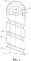
- the flexible section 102 may include grooves 108 that spiral, or otherwise extend around and/or along an outer diameter 110 of the flexible section 102.
- the grooves 108 facilitate the transition of liberated material out of the passage 22, similar to how material travels up the grooves in a drill.
- the flexible section 102 may be driven in a rotary manner.
- the rotary motion may be continuous or oscillatory in nature to further smooth the passage 22 as the tool 100 "burrows" through the partially sintered powder that is trapped in the passage 22.
- a lubricant passage 114 may be formed within the flexible section 102 and the head 104 to excrete, spray, or otherwise supply a lubricant through one or more openings 116.
- the tool 100 facilitates a uniform surface finish throughout an additively manufactured passage as well as removes material from passage such as waste finish material and sintered material.
- the tool 100 may also be tailored to each passage 22 for material removal and surface finish by adjusting amplitude, frequency, speed of translation through the passage, and abrasive media.
- the tool 100 is scalable and may permit hone/finish passage operations to a desired final diameter and target surface finish.
- one disclosed non-limiting embodiment of a method 200 to additively manufacture the component 20 initially includes additively manufacturing the component 20 with an internal passage 22 (step 210).
- the internal passage 22 is often a non-line of sight passage.
- conglomerated powder 50 is removed from the external surfaces of the completed additively manufactured component 20 (step 220; Figure 5 ). Removal is conventional and may include the use of accelerated media blast, mechanically scraping, vibratory or other methods.
- the tool 100 is burrowed into the internal passage 22 to mechanically work the conglomerated powder 50 out of the internal passage 22 (step 230). That is, the conglomerated powder 50 may be relatively compacted and the tool 100 operates to clean the internal passage 22 of the conglomerated powder 50. As described above, a positive force and/or rotation can be applied to the tool 100 to translate the tool 100 through the passage 22 to remove the conglomerated powder and surface finish the inner diameter of the internal passage 22. Further, the exciter 106 may be adjusted for amplitude and frequency to cause the head 104 to vibrate in a manner to provide relatively uniform radial contact within the passage 22.
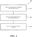
- the utilization of the tool 100 readily facilitates direct and rapid removal of the conglomerated powder from within internal passages.
Landscapes
- Engineering & Computer Science (AREA)
- Mechanical Engineering (AREA)
- Manufacturing & Machinery (AREA)
- Chemical & Material Sciences (AREA)
- Materials Engineering (AREA)
- Physics & Mathematics (AREA)
- Optics & Photonics (AREA)
- Powder Metallurgy (AREA)
Abstract
Description
- The present disclosure relates to additive manufacturing and, more particularly, to removing conglomerated powder from within an internal passage.
- Precision engineered parts such as gas turbine components may be manufactured by an additive manufacturing operation such that features associated with conventional manufacturing processes, e.g., machining, forging, welding, casting, etc. can be eliminated to facilitate savings in cost, material, and time. Additive manufacturing often results in conglomerated powder building-up around, and within, the completed component as an artifact of the process. When additive manufacturing a component that has internal passages, this conglomerated powder often becomes entrapped in the internal passages and is difficult to remove.
- There are currently few methods that directly and rapidly remove the conglomerated powder. One standard practice may include repeated use of an accelerated media blast, combined with mechanically scraping. Another standard practice includes, mega sonic or ultrasonic vibratory methods to liberate the powder particles. Oftentimes, such practices are still inefficient at removal of removing conglomerated powder from within the internal passages.
- Additively manufactured passages have a non-uniform roughness that varies both circumferentially as well as axially. The circumferential variation is a direct effect of layering nature of both a deposition and powder bed processes. The finish is finest on the bottom and progressively deteriorates towards the roof of the passage on horizontal passages with respect to the layered deposition process, while vertical passages will have a relatively uniform finish. In addition, the Electron Beam Melting additive process partially sinters material in the formed passage making powder removal difficult in such passages.
- A tool according to one disclosed non-limiting embodiment of the present disclosure can include a flexible section; a head that extends from the flexible section; and an exciter within the head.
- A further embodiment of the present disclosure may include an abrasive material on the head.
- In a further embodiment of the present disclosure, the exciter is at least one of an ultrasonic, piezo, hydraulic, and pneumatic exciter.
- A further embodiment of the present disclosure may include at least one groove within an outer diameter of the flexible section.
- In a further embodiment of the present disclosure, the at least one groove spirals around the outer diameter of the flexible section.
- A further embodiment of the present disclosure may include a lubrication passage through the flexible section to excrete a lubricant from the head.
- In a further embodiment of the present disclosure, the flexible section is rotatable.
- A method of additively manufacturing a component according to another disclosed non-limiting embodiment of the present disclosure can include burrowing a tool into conglomerated powder within an internal passage of an additively manufactured component, the tool vibrating in a manner to facilitate removal of the conglomerated powder.
- A further embodiment of the present disclosure may include cleaning the internal passage of the conglomerated powder with the tool subsequent to completion of the additively manufactured component.
- A further embodiment of the present disclosure may include abrading the local surface of the internal passage to provide a desired uniform surface finish.
- A further embodiment of the present disclosure may include abrading a local surface of the internal passage with an abrasive on the tool to provide a desired uniform surface finish.
- A further embodiment of the present disclosure may include rotating the tool within the internal passage.
- A further embodiment of the present disclosure may include transporting the conglomerated powder out of the internal passage along spiral grooves in the tool.
- A further embodiment of the present disclosure may include transporting the conglomerated powder out of the internal passage along grooves in the tool.
- A further embodiment of the present disclosure may include discharging a lubricant from the tool.
- A further embodiment of the present disclosure may include adjusting an amplitude and frequency of the exciter to vibrate the tool in a manner to provide relatively uniform radial contact within the internal passage.
- In a further embodiment of the present disclosure, the internal passage defines an aspect ratio with a diameter to length of less that 1:4.
- A further embodiment of the present disclosure may include, wherein the internal passage is a non-line of sight passage.
- The foregoing features and elements may be combined in various combinations without exclusivity, unless expressly indicated otherwise. These features and elements as well as the operation thereof will become more apparent in light of the following description and the accompanying drawings. It should be understood, however, the following description and drawings are intended to be exemplary in nature and non-limiting.
- Various features will become apparent to those skilled in the art from the following detailed description of the disclosed non-limiting embodiment. The components in the drawings are not necessarily to scale. Moreover, in the drawings, like reference numerals designate corresponding parts throughout the several views. The drawings that accompany the detailed description can be briefly described as follows:
-
Figure 1 is a perspective view of a representative additively manufactured component. -
Figure 2 is an expanded head view of the tool according to one disclosed non-limiting embodiment. -
Figure 3 is a perspective view of the additively manufactured component ofFigure 1 with a tool according to one disclosed non-limiting embodiment for removing conglomerated powder from within the internal passage. -
Figure 4 is a method of additively manufacturing a component according to one disclosed non-limiting embodiment. -
Figure 5 is a perspective view of one step in the method of additively manufacturing a component. -
Figure 1 schematically illustrates acomponent 20 that includes aninternal passage 22. In this example, thecomponent 20 may be a conduit such as that of a manifold, duct, flow passage, or other such component. Thecomponent 20 may include afirst flange 24, asecond flange 26, and aconduit 28 with theinternal passage 22 therebetween. Theinternal passage 22 may be complex and be of a non-line of sight geometry that includes multiple bends. It should be appreciated that various additional or alternative segments and/or fittings may also be provided. It should be further appreciated that although a conduit type example is illustrated herein, other aerospace components, aircraft structures, as well as a wide variety of applications outside the aerospace industry, which include relatively weak partially sintered metallic powder found inside deep recesses, holes, passages, and internal cavities will benefit herefrom. - The
component 20 may be readily manufactured with an additive manufacturing process that includes but are not limited to, Sterolithography (SLA), Direct Selective Laser Sintering (DSLS), Electron Beam Sintering (EBS), Electron Beam Melting (EBM), Laser Engineered Net Shaping (LENS), Laser Net Shape Manufacturing (LNSM), Direct Metal Deposition (DMD), Laser Powder Bed Fusion (LPBF) and others. Although particular additive manufacturing processes are disclosed, those skilled in the art of manufacturing will recognize that any other suitable rapid manufacturing methods using layer-by-layer construction or additive fabrication can alternatively be used. - The additive manufacturing process sequentially builds-up layers of atomized alloy and/or ceramic powder material that include but are not limited to, steel alloys, stainless steel alloys, titanium alloys, nickel alloys, aluminum alloys and others in atomized powder material form. Nickel alloys may have specific benefit for parts that operate in high temperature environments, such as, for example, environments typically encountered by aerospace and gas turbine engine components.
- The additive manufacturing process fabricates or "grows" of components using three-dimensional information, for example a three-dimensional computer model. The three-dimensional information is converted into a plurality of slices, each slice defining a cross section of the component for a predetermined height of the slice. The additive manufactured
component 20 is then "grown" slice-by-slice, or layer-by-layer, until finished. Each layer has an example size between about 0.0005 - 0.001 inches (0.0127 - 0.0254 mm). The additive manufacturing process facilitates manufacture of the relatively complex internal passage geometry to minimize assembly details, gun-drilling, and multi-component construction. - In one example, the
internal passage 22 may define an aspect ratio with a diameter to length of less that 1:4 and may be a non-line of sight, e.g., non-straight passage. In this non-limiting dimension embodiment, the internal diameter 22D dimension of theinternal passage 22 is between about 0.25 and 2.0 inches (about 6-50 mm) in diameter. It should be appreciated that this is but one example, and various relationship may otherwise benefit herefrom. - With reference to
Figure 2 , a tool 100, according to one disclosed non-limiting embodiment, is schematically illustrated. The tool 100 operates as an abrasive "worm" to surface finish a passage such as theinternal passage 22 and to remove partially sintered non-line of sight material blocking or conglomerated powder theinternal passage 22. The tool generally includes aflexible section 102, ahead 104, and anexciter 106. Theflexible section 102 originates with thehead 104 and may be sized to the particularinternal passage 22 to provide the desired diameter thereof. That is, the diameter of theflexible section 102 provides a desired surface finish to theinternal passage 22. The size (diameter, length) of the tool 100 may also be readily scaled to conform with conventional metric or standard hole diameters or custom built to a desired diameter and length. - The
exciter 106 may include, for example, an ultrasonic, piezo, hydraulic, pneumatic, etc., that can be adjusted for amplitude and frequency to cause thehead 104 to vibrate in a manner to provide relatively uniform radial contact within the passage 22 (Figure 3 ). Thehead 104 may be coated with a soft or hard abrasive 112 as required by the necessary finish and parent additive manufacturing material. The abrasive 112 facilitates abrasion of the local surfaces of thepassage 22 generated by theexciter 106 to provide a desired uniform radial finish. - A positive force can be applied to the tool 100 to translate the tool 100 through the
passage 22 to surface finish the inner diameter of theinternal passage 22. A user may manually apply the positive force or such force may be computer controlled and automated. The fully sintered outer diameter wall of theinternal passage 22 encapsulates the tool 100 to self-guide along theinternal passage 22. - The
flexible section 102 may includegrooves 108 that spiral, or otherwise extend around and/or along anouter diameter 110 of theflexible section 102. Thegrooves 108 facilitate the transition of liberated material out of thepassage 22, similar to how material travels up the grooves in a drill. In another disclosed non-limiting embodiment, theflexible section 102 may be driven in a rotary manner. The rotary motion may be continuous or oscillatory in nature to further smooth thepassage 22 as the tool 100 "burrows" through the partially sintered powder that is trapped in thepassage 22. To facilitate such "burrowing," a lubricant passage 114 may be formed within theflexible section 102 and thehead 104 to excrete, spray, or otherwise supply a lubricant through one ormore openings 116. - The tool 100 facilitates a uniform surface finish throughout an additively manufactured passage as well as removes material from passage such as waste finish material and sintered material. The tool 100 may also be tailored to each
passage 22 for material removal and surface finish by adjusting amplitude, frequency, speed of translation through the passage, and abrasive media. The tool 100 is scalable and may permit hone/finish passage operations to a desired final diameter and target surface finish. - With reference to
Figure 4 , one disclosed non-limiting embodiment of amethod 200 to additively manufacture thecomponent 20 initially includes additively manufacturing thecomponent 20 with an internal passage 22 (step 210). Theinternal passage 22 is often a non-line of sight passage. - Next, conglomerated
powder 50 is removed from the external surfaces of the completed additively manufactured component 20 (step 220;Figure 5 ). Removal is conventional and may include the use of accelerated media blast, mechanically scraping, vibratory or other methods. - Next, the tool 100 is burrowed into the
internal passage 22 to mechanically work the conglomeratedpowder 50 out of the internal passage 22 (step 230). That is, the conglomeratedpowder 50 may be relatively compacted and the tool 100 operates to clean theinternal passage 22 of the conglomeratedpowder 50. As described above, a positive force and/or rotation can be applied to the tool 100 to translate the tool 100 through thepassage 22 to remove the conglomerated powder and surface finish the inner diameter of theinternal passage 22. Further, theexciter 106 may be adjusted for amplitude and frequency to cause thehead 104 to vibrate in a manner to provide relatively uniform radial contact within thepassage 22. - The utilization of the tool 100 readily facilitates direct and rapid removal of the conglomerated powder from within internal passages.
- The use of the terms "a," "an," "the," and similar references in the context of description (especially in the context of the following claims) are to be construed to cover both the singular and the plural, unless otherwise indicated herein or specifically contradicted by context. The modifier "about" used in connection with a quantity is inclusive of the stated value and has the meaning dictated by the context (e.g., it includes the degree of error associated with measurement of the particular quantity). All ranges disclosed herein are inclusive of the endpoints, and the endpoints are independently combinable with each other. It should be appreciated that relative positional terms such as "forward," "aft," "upper," "lower," "above," "below," and the like are with reference to normal operational attitude and should not be considered otherwise limiting.
- Although the different non-limiting embodiments have specific illustrated components, the embodiments of this invention are not limited to those particular combinations. It is possible to use some of the components or features from any of the non-limiting embodiments in combination with features or components from any of the other non-limiting embodiments.
- It should be appreciated that like reference numerals identify corresponding or similar elements throughout the several drawings. It should also be appreciated that although a particular component arrangement is disclosed in the illustrated embodiment, other arrangements will benefit herefrom.
- Although particular step sequences are shown, described, and claimed, it should be understood that steps may be performed in any order, separated or combined unless otherwise indicated and will still benefit from the present disclosure.
- The foregoing description is exemplary rather than defined by the limitations within. Various non-limiting embodiments are disclosed herein, however, one of ordinary skill in the art would recognize that various modifications and variations in light of the above teachings will fall within the scope of the appended claims. It is therefore to be understood that within the scope of the appended claims, the disclosure may be practiced other than as specifically described. For that reason the appended claims should be studied to determine true scope and content.
Claims (15)
- A tool (100), comprising:a flexible section (102);a head (104) that extends from the flexible section (102); andan exciter (106) within the head (104).
- The tool (100) as recited in claim 1, further comprising an abrasive material (112) on the head.
- The tool (100) as recited in claim 1 or 2, wherein the exciter (106) is at least one of an ultrasonic, piezo, hydraulic, and pneumatic exciter.
- The tool (100) as recited in claim 1, 2 or 3 further comprising at least one groove (108) within an outer diameter of the flexible section (102).
- The tool (100) as recited in claim 4, wherein the at least one groove (108) spirals around the outer diameter of the flexible section (102).
- The tool (100) as recited in any preceding claim, further comprising a lubrication passage (114) through the flexible section (112) to excrete a lubricant from the head (104).
- The tool (100) as recited in any preceding claim, wherein the flexible section (102) is rotatable.
- A method of additively manufacturing a component (20), comprising:burrowing a tool (100) into conglomerated powder (50) within an internal passage (22) of an additively manufactured component (20), the tool (100) vibrating in a manner to facilitate removal of the conglomerated powder (50).
- The method as recited in claim 8, further comprising cleaning the internal passage (22) of the conglomerated powder (50) with the tool (100) subsequent to completion of the additively manufactured component (20).
- The method as recited in claim 8 or 9, further comprising abrading a local surface of the internal passage (22) to provide a desired uniform surface finish, for example by using an abrasive on the tool (100).
- The method as recited in claim 8, 9 or 10 further comprising rotating the tool (100) within the internal passage (22).
- The method as recited in any of claims 8 to 11, further comprising transporting the conglomerated powder (50) out of the internal passage (22) along grooves (108) in the tool, for example along spiral grooves (108) in the tool (100).
- The method as recited in any of claims 8 to 12, further comprising discharging a lubricant from the tool (100).
- The method as recited in any of claims 8 to 13, further comprising adjusting an amplitude and frequency of the exciter (106) to vibrate the tool (100) in a manner to provide relatively uniform radial contact within the internal passage (22).
- The method as recited in any of claims 8 to 14, wherein the internal passage (22) defines an aspect ratio with a diameter to length of less that 1:4 and/or wherein the internal passage (22) is a non-line of sight passage.
Applications Claiming Priority (1)
| Application Number | Priority Date | Filing Date | Title |
|---|---|---|---|
| US14/946,884 US10220444B2 (en) | 2015-11-20 | 2015-11-20 | Additive manufactured conglomerated powder removal from internal passages |
Publications (3)
| Publication Number | Publication Date |
|---|---|
| EP3181290A1 true EP3181290A1 (en) | 2017-06-21 |
| EP3181290B1 EP3181290B1 (en) | 2021-01-27 |
| EP3181290B8 EP3181290B8 (en) | 2021-04-07 |
Family
ID=57517677
Family Applications (1)
| Application Number | Title | Priority Date | Filing Date |
|---|---|---|---|
| EP16199684.8A Active EP3181290B8 (en) | 2015-11-20 | 2016-11-18 | Additive manufactured conglomerated powder removal from internal passages |
Country Status (2)
| Country | Link |
|---|---|
| US (2) | US10220444B2 (en) |
| EP (1) | EP3181290B8 (en) |
Families Citing this family (12)
| Publication number | Priority date | Publication date | Assignee | Title |
|---|---|---|---|---|
| GB201502086D0 (en) * | 2015-02-09 | 2015-03-25 | Rolls Royce Plc | Methods of manufacturing and cleaning |
| US10232414B2 (en) * | 2015-11-20 | 2019-03-19 | United Technologies Corporation | Additive manufactured conglomerated powder removal from internal passages |
| CN110520278B (en) * | 2017-04-24 | 2021-09-21 | 惠普发展公司,有限责任合伙企业 | Removal of excess build material in additive manufacturing |
| FR3070288B1 (en) * | 2017-08-31 | 2019-09-06 | Safran Landing Systems | METHOD FOR CLEARING PIPES IN PARTS OBTAINED BY ADDITIVE MANUFACTURING |
| US11364587B2 (en) * | 2018-04-19 | 2022-06-21 | Raytheon Technologies Corporation | Flow directors and shields for abrasive flow machining of internal passages |
| US11344949B2 (en) | 2018-06-08 | 2022-05-31 | General Electric Company | Powder removal floating structures |
| US10821485B2 (en) | 2018-06-08 | 2020-11-03 | General Electric Company | System and method of powder removal |
| DE102018125263A1 (en) * | 2018-10-12 | 2020-04-16 | Volkswagen Aktiengesellschaft | Method and device for cleaning components manufactured in a powder bed |
| US11376661B2 (en) | 2019-06-06 | 2022-07-05 | Raytheon Technologies Corporation | Apparatus and methods for improvement of surface geometries of internal channels of additively manufactured components |
| US11471947B2 (en) | 2019-06-06 | 2022-10-18 | Raytheon Technologies Corporation | Apparatus and methods for improvement of surface geometries of internal channels of additively manufactured components |
| CN115194179B (en) * | 2021-04-12 | 2024-07-05 | 中国航发商用航空发动机有限责任公司 | Support structure and method for manufacturing spiral pipeline |
| US11878470B2 (en) | 2022-03-04 | 2024-01-23 | Hamilton Sundstrand Corporation | High amplitude pneumatic impact for powder removal in additive manufacturing |
Citations (8)
| Publication number | Priority date | Publication date | Assignee | Title |
|---|---|---|---|---|
| GB191013802A (en) * | 1910-06-07 | 1910-10-13 | George Calvert | Improvements in Scarifying and Burnishing. |
| GB569133A (en) * | 1942-03-09 | 1945-05-07 | Goesta Iwarsson Lundin | A method in pressing, stamping, cutting and the like |
| US3526036A (en) * | 1968-04-01 | 1970-09-01 | Sven Karl Lennart Goof | Ultrasonic dental apparatus |
| DE3325525A1 (en) * | 1982-10-18 | 1984-04-19 | Etablissements Bordet, 93100 Montreuil sous Bois | Device for the drive of a vibratory tool |
| JP2002011009A (en) * | 2000-06-29 | 2002-01-15 | Fuji Photo Optical Co Ltd | Ultrasonic examination instrument |
| US20100147047A1 (en) * | 2007-04-12 | 2010-06-17 | Saipem S.A. | Method of Making an Udersea Pipe, the Method Including Peening Assembly Welds Inside the Pipe |
| GB2517490A (en) * | 2013-08-23 | 2015-02-25 | Univ Montfort | Additive manufacturing methods |
| CN102913121B (en) * | 2012-10-22 | 2015-04-01 | 石午江 | Flexible swing pipe vibrator boring machine |
Family Cites Families (22)
| Publication number | Priority date | Publication date | Assignee | Title |
|---|---|---|---|---|
| US1704100A (en) * | 1927-08-08 | 1929-03-05 | Clinton B Pike | Vibrating apparatus and method for its utilization for removing patterns and castings from sand molds |
| US6276018B1 (en) * | 1999-12-28 | 2001-08-21 | Basil C. Leiman | Flexible pipe cleaning device and system |
| US6995334B1 (en) | 2003-08-25 | 2006-02-07 | Southern Methodist University | System and method for controlling the size of the molten pool in laser-based additive manufacturing |
| US7777155B2 (en) | 2007-02-21 | 2010-08-17 | United Technologies Corporation | System and method for an integrated additive manufacturing cell for complex components |
| GB0816308D0 (en) | 2008-09-05 | 2008-10-15 | Mtt Technologies Ltd | Optical module |
| GB0819935D0 (en) | 2008-10-30 | 2008-12-10 | Mtt Technologies Ltd | Additive manufacturing apparatus and method |
| FR2942018B1 (en) * | 2009-02-10 | 2016-01-22 | European Aeronautic Defence & Space Co Eads France | COMPOSITE TUBULAR PIECES OF COMPLEX SHAPE |
| US8506836B2 (en) | 2011-09-16 | 2013-08-13 | Honeywell International Inc. | Methods for manufacturing components from articles formed by additive-manufacturing processes |
| US9904223B2 (en) | 2011-09-23 | 2018-02-27 | Stratasys, Inc. | Layer transfusion with transfixing for additive manufacturing |
| US8879957B2 (en) | 2011-09-23 | 2014-11-04 | Stratasys, Inc. | Electrophotography-based additive manufacturing system with reciprocating operation |
| US8488994B2 (en) | 2011-09-23 | 2013-07-16 | Stratasys, Inc. | Electrophotography-based additive manufacturing system with transfer-medium service loops |
| US9073263B2 (en) | 2011-12-22 | 2015-07-07 | Stratasys, Inc. | Spool assembly for additive manufacturing system, and methods of manufacture and use thereof |
| US8985497B2 (en) | 2011-12-22 | 2015-03-24 | Stratasys, Inc. | Consumable assembly with payout tube for additive manufacturing system |
| US9050788B2 (en) | 2011-12-22 | 2015-06-09 | Stratasys, Inc. | Universal adapter for consumable assembly used with additive manufacturing system |
| US9050753B2 (en) | 2012-03-16 | 2015-06-09 | Stratasys, Inc. | Liquefier assembly having inlet liner for use in additive manufacturing system |
| US9079803B2 (en) | 2012-04-05 | 2015-07-14 | United Technologies Corporation | Additive manufacturing hybrid core |
| US9120270B2 (en) | 2012-04-27 | 2015-09-01 | University Of Southern California | Digital mask-image-projection-based additive manufacturing that applies shearing force to detach each added layer |
| US8961167B2 (en) | 2012-12-21 | 2015-02-24 | Stratasys, Inc. | Automated additive manufacturing system for printing three-dimensional parts, printing farm thereof, and method of use thereof |
| US8695264B1 (en) * | 2013-01-08 | 2014-04-15 | Courtland Group, LLC | Gun barrel cleaning tool and method for cleaning a gun barrel |
| US9023566B2 (en) | 2013-07-17 | 2015-05-05 | Stratasys, Inc. | ABS part material for electrophotography-based additive manufacturing |
| US9029058B2 (en) | 2013-07-17 | 2015-05-12 | Stratasys, Inc. | Soluble support material for electrophotography-based additive manufacturing |
| US9023765B1 (en) | 2014-01-31 | 2015-05-05 | Jefferson Science Associates, Llc | Additive manufacturing method for SRF components of various geometries |
-
2015
- 2015-11-20 US US14/946,884 patent/US10220444B2/en active Active
-
2016
- 2016-11-18 EP EP16199684.8A patent/EP3181290B8/en active Active
-
2019
- 2019-01-22 US US16/253,501 patent/US10737363B2/en not_active Expired - Fee Related
Patent Citations (8)
| Publication number | Priority date | Publication date | Assignee | Title |
|---|---|---|---|---|
| GB191013802A (en) * | 1910-06-07 | 1910-10-13 | George Calvert | Improvements in Scarifying and Burnishing. |
| GB569133A (en) * | 1942-03-09 | 1945-05-07 | Goesta Iwarsson Lundin | A method in pressing, stamping, cutting and the like |
| US3526036A (en) * | 1968-04-01 | 1970-09-01 | Sven Karl Lennart Goof | Ultrasonic dental apparatus |
| DE3325525A1 (en) * | 1982-10-18 | 1984-04-19 | Etablissements Bordet, 93100 Montreuil sous Bois | Device for the drive of a vibratory tool |
| JP2002011009A (en) * | 2000-06-29 | 2002-01-15 | Fuji Photo Optical Co Ltd | Ultrasonic examination instrument |
| US20100147047A1 (en) * | 2007-04-12 | 2010-06-17 | Saipem S.A. | Method of Making an Udersea Pipe, the Method Including Peening Assembly Welds Inside the Pipe |
| CN102913121B (en) * | 2012-10-22 | 2015-04-01 | 石午江 | Flexible swing pipe vibrator boring machine |
| GB2517490A (en) * | 2013-08-23 | 2015-02-25 | Univ Montfort | Additive manufacturing methods |
Also Published As
| Publication number | Publication date |
|---|---|
| US10737363B2 (en) | 2020-08-11 |
| US20190152012A1 (en) | 2019-05-23 |
| EP3181290B1 (en) | 2021-01-27 |
| US20170144382A1 (en) | 2017-05-25 |
| US10220444B2 (en) | 2019-03-05 |
| EP3181290B8 (en) | 2021-04-07 |
Similar Documents
| Publication | Publication Date | Title |
|---|---|---|
| US10737363B2 (en) | Additive manufactured conglomerated powder removal from internal passages | |
| US11312064B2 (en) | Additive manufactured conglomerated powder removal from internal passages | |
| US11247250B2 (en) | Additive manufactured conglomerated powder removal from internal passages | |
| US11597014B2 (en) | Additive manufactured conglomerated powder removal from internal passages | |
| EP3199269B1 (en) | Additive manufactured conglomerated powder removal from internal passages with co-built ultrasonic horns | |
| CN110462168B (en) | Part and method for producing a part using hybrid additive manufacturing techniques | |
| US8691329B2 (en) | Laser net shape manufacturing using an adaptive toolpath deposition method | |
| US11111800B2 (en) | Method for manufacturing an impeller of a rotary machine and an impeller manufactured using such a method | |
| RU2743542C2 (en) | A method of manufacturing or repairing a part of a rotary machine, as well as a part manufactured or repaired using such a method | |
| US11648737B2 (en) | Sonotrode | |
| EP3445570B1 (en) | Method of processing a surface for additive manufacturing | |
| US20160146014A1 (en) | Modified bucket platforms of turbine buckets and methods for modifying bucket platforms of turbine buckets | |
| KR20230042714A (en) | Method for removing support structures of additive manufacturing components by pressurized jets |
Legal Events
| Date | Code | Title | Description |
|---|---|---|---|
| PUAI | Public reference made under article 153(3) epc to a published international application that has entered the european phase |
Free format text: ORIGINAL CODE: 0009012 |
|
| STAA | Information on the status of an ep patent application or granted ep patent |
Free format text: STATUS: THE APPLICATION HAS BEEN PUBLISHED |
|
| AK | Designated contracting states |
Kind code of ref document: A1 Designated state(s): AL AT BE BG CH CY CZ DE DK EE ES FI FR GB GR HR HU IE IS IT LI LT LU LV MC MK MT NL NO PL PT RO RS SE SI SK SM TR |
|
| AX | Request for extension of the european patent |
Extension state: BA ME |
|
| STAA | Information on the status of an ep patent application or granted ep patent |
Free format text: STATUS: REQUEST FOR EXAMINATION WAS MADE |
|
| 17P | Request for examination filed |
Effective date: 20171221 |
|
| RBV | Designated contracting states (corrected) |
Designated state(s): AL AT BE BG CH CY CZ DE DK EE ES FI FR GB GR HR HU IE IS IT LI LT LU LV MC MK MT NL NO PL PT RO RS SE SI SK SM TR |
|
| GRAP | Despatch of communication of intention to grant a patent |
Free format text: ORIGINAL CODE: EPIDOSNIGR1 |
|
| STAA | Information on the status of an ep patent application or granted ep patent |
Free format text: STATUS: GRANT OF PATENT IS INTENDED |
|
| RIC1 | Information provided on ipc code assigned before grant |
Ipc: B22F 3/24 20060101ALI20200506BHEP Ipc: B22F 3/105 20060101ALI20200506BHEP Ipc: B22F 5/10 20060101ALI20200506BHEP Ipc: B33Y 40/00 20200101ALI20200506BHEP Ipc: B24B 5/40 20060101ALI20200506BHEP Ipc: B24B 5/06 20060101ALI20200506BHEP Ipc: B29C 64/35 20170101ALI20200506BHEP Ipc: B24B 1/04 20060101AFI20200506BHEP |
|
| INTG | Intention to grant announced |
Effective date: 20200528 |
|
| GRAJ | Information related to disapproval of communication of intention to grant by the applicant or resumption of examination proceedings by the epo deleted |
Free format text: ORIGINAL CODE: EPIDOSDIGR1 |
|
| STAA | Information on the status of an ep patent application or granted ep patent |
Free format text: STATUS: REQUEST FOR EXAMINATION WAS MADE |
|
| GRAP | Despatch of communication of intention to grant a patent |
Free format text: ORIGINAL CODE: EPIDOSNIGR1 |
|
| STAA | Information on the status of an ep patent application or granted ep patent |
Free format text: STATUS: GRANT OF PATENT IS INTENDED |
|
| INTC | Intention to grant announced (deleted) | ||
| INTG | Intention to grant announced |
Effective date: 20200818 |
|
| GRAS | Grant fee paid |
Free format text: ORIGINAL CODE: EPIDOSNIGR3 |
|
| GRAA | (expected) grant |
Free format text: ORIGINAL CODE: 0009210 |
|
| STAA | Information on the status of an ep patent application or granted ep patent |
Free format text: STATUS: THE PATENT HAS BEEN GRANTED |
|
| AK | Designated contracting states |
Kind code of ref document: B1 Designated state(s): AL AT BE BG CH CY CZ DE DK EE ES FI FR GB GR HR HU IE IS IT LI LT LU LV MC MK MT NL NO PL PT RO RS SE SI SK SM TR |
|
| REG | Reference to a national code |
Ref country code: GB Ref legal event code: FG4D |
|
| REG | Reference to a national code |
Ref country code: CH Ref legal event code: EP |
|
| REG | Reference to a national code |
Ref country code: AT Ref legal event code: REF Ref document number: 1357906 Country of ref document: AT Kind code of ref document: T Effective date: 20210215 |
|
| REG | Reference to a national code |
Ref country code: IE Ref legal event code: FG4D |
|
| REG | Reference to a national code |
Ref country code: DE Ref legal event code: R096 Ref document number: 602016051997 Country of ref document: DE |
|
| GRAT | Correction requested after decision to grant or after decision to maintain patent in amended form |
Free format text: ORIGINAL CODE: EPIDOSNCDEC |
|
| REG | Reference to a national code |
Ref country code: DE Ref legal event code: R081 Ref document number: 602016051997 Country of ref document: DE Owner name: RAYTHEON TECHNOLOGIES CORPORATION, FARMINGTON, US Free format text: FORMER OWNER: UNITED TECHNOLOGIES CORPORATION, FARMINGTON, CONN., US |
|
| REG | Reference to a national code |
Ref country code: CH Ref legal event code: PK Free format text: BERICHTIGUNG B8 |
|
| RAP2 | Party data changed (patent owner data changed or rights of a patent transferred) |
Owner name: RAYTHEON TECHNOLOGIES CORPORATION |
|
| REG | Reference to a national code |
Ref country code: NL Ref legal event code: MP Effective date: 20210127 |
|
| REG | Reference to a national code |
Ref country code: LT Ref legal event code: MG9D |
|
| REG | Reference to a national code |
Ref country code: AT Ref legal event code: MK05 Ref document number: 1357906 Country of ref document: AT Kind code of ref document: T Effective date: 20210127 |
|
| PG25 | Lapsed in a contracting state [announced via postgrant information from national office to epo] |
Ref country code: GR Free format text: LAPSE BECAUSE OF FAILURE TO SUBMIT A TRANSLATION OF THE DESCRIPTION OR TO PAY THE FEE WITHIN THE PRESCRIBED TIME-LIMIT Effective date: 20210428 Ref country code: FI Free format text: LAPSE BECAUSE OF FAILURE TO SUBMIT A TRANSLATION OF THE DESCRIPTION OR TO PAY THE FEE WITHIN THE PRESCRIBED TIME-LIMIT Effective date: 20210127 Ref country code: HR Free format text: LAPSE BECAUSE OF FAILURE TO SUBMIT A TRANSLATION OF THE DESCRIPTION OR TO PAY THE FEE WITHIN THE PRESCRIBED TIME-LIMIT Effective date: 20210127 Ref country code: NO Free format text: LAPSE BECAUSE OF FAILURE TO SUBMIT A TRANSLATION OF THE DESCRIPTION OR TO PAY THE FEE WITHIN THE PRESCRIBED TIME-LIMIT Effective date: 20210427 Ref country code: PT Free format text: LAPSE BECAUSE OF FAILURE TO SUBMIT A TRANSLATION OF THE DESCRIPTION OR TO PAY THE FEE WITHIN THE PRESCRIBED TIME-LIMIT Effective date: 20210527 Ref country code: BG Free format text: LAPSE BECAUSE OF FAILURE TO SUBMIT A TRANSLATION OF THE DESCRIPTION OR TO PAY THE FEE WITHIN THE PRESCRIBED TIME-LIMIT Effective date: 20210427 Ref country code: NL Free format text: LAPSE BECAUSE OF FAILURE TO SUBMIT A TRANSLATION OF THE DESCRIPTION OR TO PAY THE FEE WITHIN THE PRESCRIBED TIME-LIMIT Effective date: 20210127 Ref country code: LT Free format text: LAPSE BECAUSE OF FAILURE TO SUBMIT A TRANSLATION OF THE DESCRIPTION OR TO PAY THE FEE WITHIN THE PRESCRIBED TIME-LIMIT Effective date: 20210127 |
|
| PG25 | Lapsed in a contracting state [announced via postgrant information from national office to epo] |
Ref country code: SE Free format text: LAPSE BECAUSE OF FAILURE TO SUBMIT A TRANSLATION OF THE DESCRIPTION OR TO PAY THE FEE WITHIN THE PRESCRIBED TIME-LIMIT Effective date: 20210127 Ref country code: PL Free format text: LAPSE BECAUSE OF FAILURE TO SUBMIT A TRANSLATION OF THE DESCRIPTION OR TO PAY THE FEE WITHIN THE PRESCRIBED TIME-LIMIT Effective date: 20210127 Ref country code: LV Free format text: LAPSE BECAUSE OF FAILURE TO SUBMIT A TRANSLATION OF THE DESCRIPTION OR TO PAY THE FEE WITHIN THE PRESCRIBED TIME-LIMIT Effective date: 20210127 Ref country code: RS Free format text: LAPSE BECAUSE OF FAILURE TO SUBMIT A TRANSLATION OF THE DESCRIPTION OR TO PAY THE FEE WITHIN THE PRESCRIBED TIME-LIMIT Effective date: 20210127 Ref country code: AT Free format text: LAPSE BECAUSE OF FAILURE TO SUBMIT A TRANSLATION OF THE DESCRIPTION OR TO PAY THE FEE WITHIN THE PRESCRIBED TIME-LIMIT Effective date: 20210127 |
|
| PG25 | Lapsed in a contracting state [announced via postgrant information from national office to epo] |
Ref country code: IS Free format text: LAPSE BECAUSE OF FAILURE TO SUBMIT A TRANSLATION OF THE DESCRIPTION OR TO PAY THE FEE WITHIN THE PRESCRIBED TIME-LIMIT Effective date: 20210527 |
|
| REG | Reference to a national code |
Ref country code: DE Ref legal event code: R097 Ref document number: 602016051997 Country of ref document: DE |
|
| PG25 | Lapsed in a contracting state [announced via postgrant information from national office to epo] |
Ref country code: EE Free format text: LAPSE BECAUSE OF FAILURE TO SUBMIT A TRANSLATION OF THE DESCRIPTION OR TO PAY THE FEE WITHIN THE PRESCRIBED TIME-LIMIT Effective date: 20210127 Ref country code: CZ Free format text: LAPSE BECAUSE OF FAILURE TO SUBMIT A TRANSLATION OF THE DESCRIPTION OR TO PAY THE FEE WITHIN THE PRESCRIBED TIME-LIMIT Effective date: 20210127 Ref country code: SM Free format text: LAPSE BECAUSE OF FAILURE TO SUBMIT A TRANSLATION OF THE DESCRIPTION OR TO PAY THE FEE WITHIN THE PRESCRIBED TIME-LIMIT Effective date: 20210127 |
|
| PG25 | Lapsed in a contracting state [announced via postgrant information from national office to epo] |
Ref country code: DK Free format text: LAPSE BECAUSE OF FAILURE TO SUBMIT A TRANSLATION OF THE DESCRIPTION OR TO PAY THE FEE WITHIN THE PRESCRIBED TIME-LIMIT Effective date: 20210127 Ref country code: SK Free format text: LAPSE BECAUSE OF FAILURE TO SUBMIT A TRANSLATION OF THE DESCRIPTION OR TO PAY THE FEE WITHIN THE PRESCRIBED TIME-LIMIT Effective date: 20210127 Ref country code: RO Free format text: LAPSE BECAUSE OF FAILURE TO SUBMIT A TRANSLATION OF THE DESCRIPTION OR TO PAY THE FEE WITHIN THE PRESCRIBED TIME-LIMIT Effective date: 20210127 |
|
| PLBE | No opposition filed within time limit |
Free format text: ORIGINAL CODE: 0009261 |
|
| STAA | Information on the status of an ep patent application or granted ep patent |
Free format text: STATUS: NO OPPOSITION FILED WITHIN TIME LIMIT |
|
| 26N | No opposition filed |
Effective date: 20211028 |
|
| PG25 | Lapsed in a contracting state [announced via postgrant information from national office to epo] |
Ref country code: AL Free format text: LAPSE BECAUSE OF FAILURE TO SUBMIT A TRANSLATION OF THE DESCRIPTION OR TO PAY THE FEE WITHIN THE PRESCRIBED TIME-LIMIT Effective date: 20210127 Ref country code: ES Free format text: LAPSE BECAUSE OF FAILURE TO SUBMIT A TRANSLATION OF THE DESCRIPTION OR TO PAY THE FEE WITHIN THE PRESCRIBED TIME-LIMIT Effective date: 20210127 |
|
| PG25 | Lapsed in a contracting state [announced via postgrant information from national office to epo] |
Ref country code: SI Free format text: LAPSE BECAUSE OF FAILURE TO SUBMIT A TRANSLATION OF THE DESCRIPTION OR TO PAY THE FEE WITHIN THE PRESCRIBED TIME-LIMIT Effective date: 20210127 |
|
| PG25 | Lapsed in a contracting state [announced via postgrant information from national office to epo] |
Ref country code: IT Free format text: LAPSE BECAUSE OF FAILURE TO SUBMIT A TRANSLATION OF THE DESCRIPTION OR TO PAY THE FEE WITHIN THE PRESCRIBED TIME-LIMIT Effective date: 20210127 |
|
| PG25 | Lapsed in a contracting state [announced via postgrant information from national office to epo] |
Ref country code: IS Free format text: LAPSE BECAUSE OF FAILURE TO SUBMIT A TRANSLATION OF THE DESCRIPTION OR TO PAY THE FEE WITHIN THE PRESCRIBED TIME-LIMIT Effective date: 20210527 |
|
| PG25 | Lapsed in a contracting state [announced via postgrant information from national office to epo] |
Ref country code: MC Free format text: LAPSE BECAUSE OF FAILURE TO SUBMIT A TRANSLATION OF THE DESCRIPTION OR TO PAY THE FEE WITHIN THE PRESCRIBED TIME-LIMIT Effective date: 20210127 |
|
| REG | Reference to a national code |
Ref country code: CH Ref legal event code: PL |
|
| PG25 | Lapsed in a contracting state [announced via postgrant information from national office to epo] |
Ref country code: LU Free format text: LAPSE BECAUSE OF NON-PAYMENT OF DUE FEES Effective date: 20211118 Ref country code: BE Free format text: LAPSE BECAUSE OF NON-PAYMENT OF DUE FEES Effective date: 20211130 |
|
| REG | Reference to a national code |
Ref country code: BE Ref legal event code: MM Effective date: 20211130 |
|
| PG25 | Lapsed in a contracting state [announced via postgrant information from national office to epo] |
Ref country code: IE Free format text: LAPSE BECAUSE OF NON-PAYMENT OF DUE FEES Effective date: 20211118 |
|
| PGFP | Annual fee paid to national office [announced via postgrant information from national office to epo] |
Ref country code: FR Payment date: 20221021 Year of fee payment: 7 |
|
| PGFP | Annual fee paid to national office [announced via postgrant information from national office to epo] |
Ref country code: GB Payment date: 20221021 Year of fee payment: 7 Ref country code: DE Payment date: 20220616 Year of fee payment: 7 |
|
| PG25 | Lapsed in a contracting state [announced via postgrant information from national office to epo] |
Ref country code: HU Free format text: LAPSE BECAUSE OF FAILURE TO SUBMIT A TRANSLATION OF THE DESCRIPTION OR TO PAY THE FEE WITHIN THE PRESCRIBED TIME-LIMIT; INVALID AB INITIO Effective date: 20161118 |
|
| P01 | Opt-out of the competence of the unified patent court (upc) registered |
Effective date: 20230520 |
|
| PG25 | Lapsed in a contracting state [announced via postgrant information from national office to epo] |
Ref country code: CY Free format text: LAPSE BECAUSE OF FAILURE TO SUBMIT A TRANSLATION OF THE DESCRIPTION OR TO PAY THE FEE WITHIN THE PRESCRIBED TIME-LIMIT Effective date: 20210127 |
|
| PG25 | Lapsed in a contracting state [announced via postgrant information from national office to epo] |
Ref country code: LI Free format text: LAPSE BECAUSE OF NON-PAYMENT OF DUE FEES Effective date: 20220630 Ref country code: CH Free format text: LAPSE BECAUSE OF NON-PAYMENT OF DUE FEES Effective date: 20220630 |
|
| PG25 | Lapsed in a contracting state [announced via postgrant information from national office to epo] |
Ref country code: MK Free format text: LAPSE BECAUSE OF FAILURE TO SUBMIT A TRANSLATION OF THE DESCRIPTION OR TO PAY THE FEE WITHIN THE PRESCRIBED TIME-LIMIT Effective date: 20210127 |
|
| REG | Reference to a national code |
Ref country code: DE Ref legal event code: R119 Ref document number: 602016051997 Country of ref document: DE |
|
| GBPC | Gb: european patent ceased through non-payment of renewal fee |
Effective date: 20231118 |
|
| PG25 | Lapsed in a contracting state [announced via postgrant information from national office to epo] |
Ref country code: MT Free format text: LAPSE BECAUSE OF FAILURE TO SUBMIT A TRANSLATION OF THE DESCRIPTION OR TO PAY THE FEE WITHIN THE PRESCRIBED TIME-LIMIT Effective date: 20210127 |