EP3181037A1 - Electrode needle, biological information measuring device, and liquid supply device - Google Patents
Electrode needle, biological information measuring device, and liquid supply device Download PDFInfo
- Publication number
- EP3181037A1 EP3181037A1 EP16204023.2A EP16204023A EP3181037A1 EP 3181037 A1 EP3181037 A1 EP 3181037A1 EP 16204023 A EP16204023 A EP 16204023A EP 3181037 A1 EP3181037 A1 EP 3181037A1
- Authority
- EP
- European Patent Office
- Prior art keywords
- electrode
- electrode needle
- needle
- section
- supply device
- Prior art date
- Legal status (The legal status is an assumption and is not a legal conclusion. Google has not performed a legal analysis and makes no representation as to the accuracy of the status listed.)
- Withdrawn
Links
- 239000007788 liquid Substances 0.000 title claims description 52
- 238000001514 detection method Methods 0.000 claims abstract description 94
- 239000011810 insulating material Substances 0.000 claims abstract description 12
- NOESYZHRGYRDHS-UHFFFAOYSA-N insulin Chemical compound N1C(=O)C(NC(=O)C(CCC(N)=O)NC(=O)C(CCC(O)=O)NC(=O)C(C(C)C)NC(=O)C(NC(=O)CN)C(C)CC)CSSCC(C(NC(CO)C(=O)NC(CC(C)C)C(=O)NC(CC=2C=CC(O)=CC=2)C(=O)NC(CCC(N)=O)C(=O)NC(CC(C)C)C(=O)NC(CCC(O)=O)C(=O)NC(CC(N)=O)C(=O)NC(CC=2C=CC(O)=CC=2)C(=O)NC(CSSCC(NC(=O)C(C(C)C)NC(=O)C(CC(C)C)NC(=O)C(CC=2C=CC(O)=CC=2)NC(=O)C(CC(C)C)NC(=O)C(C)NC(=O)C(CCC(O)=O)NC(=O)C(C(C)C)NC(=O)C(CC(C)C)NC(=O)C(CC=2NC=NC=2)NC(=O)C(CO)NC(=O)CNC2=O)C(=O)NCC(=O)NC(CCC(O)=O)C(=O)NC(CCCNC(N)=N)C(=O)NCC(=O)NC(CC=3C=CC=CC=3)C(=O)NC(CC=3C=CC=CC=3)C(=O)NC(CC=3C=CC(O)=CC=3)C(=O)NC(C(C)O)C(=O)N3C(CCC3)C(=O)NC(CCCCN)C(=O)NC(C)C(O)=O)C(=O)NC(CC(N)=O)C(O)=O)=O)NC(=O)C(C(C)CC)NC(=O)C(CO)NC(=O)C(C(C)O)NC(=O)C1CSSCC2NC(=O)C(CC(C)C)NC(=O)C(NC(=O)C(CCC(N)=O)NC(=O)C(CC(N)=O)NC(=O)C(NC(=O)C(N)CC=1C=CC=CC=1)C(C)C)CC1=CN=CN1 NOESYZHRGYRDHS-UHFFFAOYSA-N 0.000 claims description 186
- 102000004877 Insulin Human genes 0.000 claims description 93
- 108090001061 Insulin Proteins 0.000 claims description 93
- 229940125396 insulin Drugs 0.000 claims description 93
- WQZGKKKJIJFFOK-GASJEMHNSA-N Glucose Natural products OC[C@H]1OC(O)[C@H](O)[C@@H](O)[C@@H]1O WQZGKKKJIJFFOK-GASJEMHNSA-N 0.000 claims description 73
- 239000008103 glucose Substances 0.000 claims description 73
- 108090000790 Enzymes Proteins 0.000 claims description 21
- 102000004190 Enzymes Human genes 0.000 claims description 21
- 238000005259 measurement Methods 0.000 description 28
- BASFCYQUMIYNBI-UHFFFAOYSA-N platinum Chemical compound [Pt] BASFCYQUMIYNBI-UHFFFAOYSA-N 0.000 description 21
- 229940088598 enzyme Drugs 0.000 description 20
- 238000002347 injection Methods 0.000 description 20
- 239000007924 injection Substances 0.000 description 20
- 210000003722 extracellular fluid Anatomy 0.000 description 19
- 210000001519 tissue Anatomy 0.000 description 18
- 239000000463 material Substances 0.000 description 16
- 238000010586 diagram Methods 0.000 description 13
- MHAJPDPJQMAIIY-UHFFFAOYSA-N Hydrogen peroxide Chemical compound OO MHAJPDPJQMAIIY-UHFFFAOYSA-N 0.000 description 12
- 238000006243 chemical reaction Methods 0.000 description 12
- 230000000694 effects Effects 0.000 description 10
- 238000005192 partition Methods 0.000 description 10
- 238000004519 manufacturing process Methods 0.000 description 9
- 206010033675 panniculitis Diseases 0.000 description 9
- 229910052697 platinum Inorganic materials 0.000 description 9
- 239000010935 stainless steel Substances 0.000 description 9
- 229910001220 stainless steel Inorganic materials 0.000 description 9
- 210000004304 subcutaneous tissue Anatomy 0.000 description 9
- 238000006911 enzymatic reaction Methods 0.000 description 8
- 238000003780 insertion Methods 0.000 description 8
- 230000037431 insertion Effects 0.000 description 8
- 230000002159 abnormal effect Effects 0.000 description 7
- QVGXLLKOCUKJST-UHFFFAOYSA-N atomic oxygen Chemical compound [O] QVGXLLKOCUKJST-UHFFFAOYSA-N 0.000 description 7
- 239000001301 oxygen Substances 0.000 description 7
- 229910052760 oxygen Inorganic materials 0.000 description 7
- 238000007747 plating Methods 0.000 description 7
- BQCADISMDOOEFD-UHFFFAOYSA-N Silver Chemical compound [Ag] BQCADISMDOOEFD-UHFFFAOYSA-N 0.000 description 6
- 229910052709 silver Inorganic materials 0.000 description 6
- 239000004332 silver Substances 0.000 description 6
- 239000000758 substrate Substances 0.000 description 6
- 239000004809 Teflon Substances 0.000 description 5
- 229920006362 Teflon® Polymers 0.000 description 5
- 229920005989 resin Polymers 0.000 description 5
- 239000011347 resin Substances 0.000 description 5
- 238000007920 subcutaneous administration Methods 0.000 description 5
- RZVAJINKPMORJF-UHFFFAOYSA-N Acetaminophen Chemical compound CC(=O)NC1=CC=C(O)C=C1 RZVAJINKPMORJF-UHFFFAOYSA-N 0.000 description 4
- CIWBSHSKHKDKBQ-JLAZNSOCSA-N Ascorbic acid Chemical compound OC[C@H](O)[C@H]1OC(=O)C(O)=C1O CIWBSHSKHKDKBQ-JLAZNSOCSA-N 0.000 description 4
- 229940081735 acetylcellulose Drugs 0.000 description 4
- 210000004369 blood Anatomy 0.000 description 4
- 239000008280 blood Substances 0.000 description 4
- 229920002301 cellulose acetate Polymers 0.000 description 4
- 238000005520 cutting process Methods 0.000 description 4
- 239000010931 gold Substances 0.000 description 4
- -1 polybutylene terephthalate Polymers 0.000 description 4
- 229920003002 synthetic resin Polymers 0.000 description 4
- 239000000057 synthetic resin Substances 0.000 description 4
- 239000004366 Glucose oxidase Substances 0.000 description 3
- 108010015776 Glucose oxidase Proteins 0.000 description 3
- 239000004642 Polyimide Substances 0.000 description 3
- 239000000853 adhesive Substances 0.000 description 3
- 230000001070 adhesive effect Effects 0.000 description 3
- 239000000919 ceramic Substances 0.000 description 3
- 206010012601 diabetes mellitus Diseases 0.000 description 3
- 229940116332 glucose oxidase Drugs 0.000 description 3
- 235000019420 glucose oxidase Nutrition 0.000 description 3
- 229910052751 metal Inorganic materials 0.000 description 3
- 239000002184 metal Substances 0.000 description 3
- 230000035699 permeability Effects 0.000 description 3
- 229920001721 polyimide Polymers 0.000 description 3
- 239000000126 substance Substances 0.000 description 3
- 102000009027 Albumins Human genes 0.000 description 2
- 108010088751 Albumins Proteins 0.000 description 2
- 239000004952 Polyamide Substances 0.000 description 2
- 239000004743 Polypropylene Substances 0.000 description 2
- 239000004372 Polyvinyl alcohol Substances 0.000 description 2
- LEHOTFFKMJEONL-UHFFFAOYSA-N Uric Acid Chemical compound N1C(=O)NC(=O)C2=C1NC(=O)N2 LEHOTFFKMJEONL-UHFFFAOYSA-N 0.000 description 2
- TVWHNULVHGKJHS-UHFFFAOYSA-N Uric acid Natural products N1C(=O)NC(=O)C2NC(=O)NC21 TVWHNULVHGKJHS-UHFFFAOYSA-N 0.000 description 2
- SMEGJBVQLJJKKX-HOTMZDKISA-N [(2R,3S,4S,5R,6R)-5-acetyloxy-3,4,6-trihydroxyoxan-2-yl]methyl acetate Chemical compound CC(=O)OC[C@@H]1[C@H]([C@@H]([C@H]([C@@H](O1)O)OC(=O)C)O)O SMEGJBVQLJJKKX-HOTMZDKISA-N 0.000 description 2
- 210000001015 abdomen Anatomy 0.000 description 2
- 229910045601 alloy Inorganic materials 0.000 description 2
- 239000000956 alloy Substances 0.000 description 2
- 235000010323 ascorbic acid Nutrition 0.000 description 2
- 229960005070 ascorbic acid Drugs 0.000 description 2
- 239000011668 ascorbic acid Substances 0.000 description 2
- 238000005452 bending Methods 0.000 description 2
- 150000001875 compounds Chemical class 0.000 description 2
- 238000005868 electrolysis reaction Methods 0.000 description 2
- 239000003822 epoxy resin Substances 0.000 description 2
- PCHJSUWPFVWCPO-UHFFFAOYSA-N gold Chemical compound [Au] PCHJSUWPFVWCPO-UHFFFAOYSA-N 0.000 description 2
- 229910052737 gold Inorganic materials 0.000 description 2
- GPRLSGONYQIRFK-UHFFFAOYSA-N hydron Chemical compound [H+] GPRLSGONYQIRFK-UHFFFAOYSA-N 0.000 description 2
- 230000003914 insulin secretion Effects 0.000 description 2
- 229920000609 methyl cellulose Polymers 0.000 description 2
- 239000001923 methylcellulose Substances 0.000 description 2
- 238000012806 monitoring device Methods 0.000 description 2
- 229960005489 paracetamol Drugs 0.000 description 2
- 239000012466 permeate Substances 0.000 description 2
- 238000005498 polishing Methods 0.000 description 2
- 229920002647 polyamide Polymers 0.000 description 2
- 229920001707 polybutylene terephthalate Polymers 0.000 description 2
- 229920000647 polyepoxide Polymers 0.000 description 2
- 229920000139 polyethylene terephthalate Polymers 0.000 description 2
- 239000005020 polyethylene terephthalate Substances 0.000 description 2
- 229920001155 polypropylene Polymers 0.000 description 2
- 229920002635 polyurethane Polymers 0.000 description 2
- 239000004814 polyurethane Substances 0.000 description 2
- 229920002451 polyvinyl alcohol Polymers 0.000 description 2
- 229920000036 polyvinylpyrrolidone Polymers 0.000 description 2
- 239000001267 polyvinylpyrrolidone Substances 0.000 description 2
- 235000013855 polyvinylpyrrolidone Nutrition 0.000 description 2
- 229920006395 saturated elastomer Polymers 0.000 description 2
- 229920006305 unsaturated polyester Polymers 0.000 description 2
- 229940116269 uric acid Drugs 0.000 description 2
- NDWUBGAGUCISDV-UHFFFAOYSA-N 4-hydroxybutyl prop-2-enoate Chemical group OCCCCOC(=O)C=C NDWUBGAGUCISDV-UHFFFAOYSA-N 0.000 description 1
- RGHNJXZEOKUKBD-UHFFFAOYSA-N D-gluconic acid Natural products OCC(O)C(O)C(O)C(O)C(O)=O RGHNJXZEOKUKBD-UHFFFAOYSA-N 0.000 description 1
- RGHNJXZEOKUKBD-SQOUGZDYSA-N Gluconic acid Natural products OC[C@@H](O)[C@@H](O)[C@H](O)[C@@H](O)C(O)=O RGHNJXZEOKUKBD-SQOUGZDYSA-N 0.000 description 1
- 208000012266 Needlestick injury Diseases 0.000 description 1
- 239000002202 Polyethylene glycol Substances 0.000 description 1
- 229910021607 Silver chloride Inorganic materials 0.000 description 1
- FOIXSVOLVBLSDH-UHFFFAOYSA-N Silver ion Chemical compound [Ag+] FOIXSVOLVBLSDH-UHFFFAOYSA-N 0.000 description 1
- 238000005299 abrasion Methods 0.000 description 1
- NIXOWILDQLNWCW-UHFFFAOYSA-N acrylic acid group Chemical group C(C=C)(=O)O NIXOWILDQLNWCW-UHFFFAOYSA-N 0.000 description 1
- 230000001154 acute effect Effects 0.000 description 1
- PNEYBMLMFCGWSK-UHFFFAOYSA-N aluminium oxide Inorganic materials [O-2].[O-2].[O-2].[Al+3].[Al+3] PNEYBMLMFCGWSK-UHFFFAOYSA-N 0.000 description 1
- 230000008901 benefit Effects 0.000 description 1
- WQZGKKKJIJFFOK-VFUOTHLCSA-N beta-D-glucose Chemical compound OC[C@H]1O[C@@H](O)[C@H](O)[C@@H](O)[C@@H]1O WQZGKKKJIJFFOK-VFUOTHLCSA-N 0.000 description 1
- 239000011230 binding agent Substances 0.000 description 1
- 230000015572 biosynthetic process Effects 0.000 description 1
- 238000010241 blood sampling Methods 0.000 description 1
- 239000003431 cross linking reagent Substances 0.000 description 1
- 230000007423 decrease Effects 0.000 description 1
- 238000007599 discharging Methods 0.000 description 1
- 238000010828 elution Methods 0.000 description 1
- 238000002474 experimental method Methods 0.000 description 1
- 235000012208 gluconic acid Nutrition 0.000 description 1
- 239000000174 gluconic acid Substances 0.000 description 1
- 238000010438 heat treatment Methods 0.000 description 1
- XLYOFNOQVPJJNP-UHFFFAOYSA-M hydroxide Chemical compound [OH-] XLYOFNOQVPJJNP-UHFFFAOYSA-M 0.000 description 1
- 125000002887 hydroxy group Chemical group [H]O* 0.000 description 1
- 238000009413 insulation Methods 0.000 description 1
- 239000012948 isocyanate Substances 0.000 description 1
- 239000004973 liquid crystal related substance Substances 0.000 description 1
- 235000012054 meals Nutrition 0.000 description 1
- 239000000203 mixture Substances 0.000 description 1
- 238000012986 modification Methods 0.000 description 1
- 230000004048 modification Effects 0.000 description 1
- 238000012544 monitoring process Methods 0.000 description 1
- 210000000496 pancreas Anatomy 0.000 description 1
- 229920002312 polyamide-imide Polymers 0.000 description 1
- 229920000515 polycarbonate Polymers 0.000 description 1
- 239000004417 polycarbonate Substances 0.000 description 1
- 229920001223 polyethylene glycol Polymers 0.000 description 1
- 239000004848 polyfunctional curative Substances 0.000 description 1
- 229920000642 polymer Polymers 0.000 description 1
- 229920002689 polyvinyl acetate Polymers 0.000 description 1
- 239000011118 polyvinyl acetate Substances 0.000 description 1
- 239000004800 polyvinyl chloride Substances 0.000 description 1
- 108090000623 proteins and genes Proteins 0.000 description 1
- 102000004169 proteins and genes Human genes 0.000 description 1
- 230000009467 reduction Effects 0.000 description 1
- HKZLPVFGJNLROG-UHFFFAOYSA-M silver monochloride Chemical compound [Cl-].[Ag+] HKZLPVFGJNLROG-UHFFFAOYSA-M 0.000 description 1
- 239000007787 solid Substances 0.000 description 1
- 230000000087 stabilizing effect Effects 0.000 description 1
- 230000004936 stimulating effect Effects 0.000 description 1
- 229920005992 thermoplastic resin Polymers 0.000 description 1
- 229920001187 thermosetting polymer Polymers 0.000 description 1
- 230000007704 transition Effects 0.000 description 1
- 229920002554 vinyl polymer Polymers 0.000 description 1
Images






Classifications
-
- A—HUMAN NECESSITIES
- A61—MEDICAL OR VETERINARY SCIENCE; HYGIENE
- A61B—DIAGNOSIS; SURGERY; IDENTIFICATION
- A61B5/00—Measuring for diagnostic purposes; Identification of persons
- A61B5/145—Measuring characteristics of blood in vivo, e.g. gas concentration or pH-value ; Measuring characteristics of body fluids or tissues, e.g. interstitial fluid or cerebral tissue
- A61B5/1468—Measuring characteristics of blood in vivo, e.g. gas concentration or pH-value ; Measuring characteristics of body fluids or tissues, e.g. interstitial fluid or cerebral tissue using chemical or electrochemical methods, e.g. by polarographic means
- A61B5/1486—Measuring characteristics of blood in vivo, e.g. gas concentration or pH-value ; Measuring characteristics of body fluids or tissues, e.g. interstitial fluid or cerebral tissue using chemical or electrochemical methods, e.g. by polarographic means using enzyme electrodes, e.g. with immobilised oxidase
- A61B5/14865—Measuring characteristics of blood in vivo, e.g. gas concentration or pH-value ; Measuring characteristics of body fluids or tissues, e.g. interstitial fluid or cerebral tissue using chemical or electrochemical methods, e.g. by polarographic means using enzyme electrodes, e.g. with immobilised oxidase invasive, e.g. introduced into the body by a catheter or needle or using implanted sensors
-
- A—HUMAN NECESSITIES
- A61—MEDICAL OR VETERINARY SCIENCE; HYGIENE
- A61B—DIAGNOSIS; SURGERY; IDENTIFICATION
- A61B5/00—Measuring for diagnostic purposes; Identification of persons
- A61B5/145—Measuring characteristics of blood in vivo, e.g. gas concentration or pH-value ; Measuring characteristics of body fluids or tissues, e.g. interstitial fluid or cerebral tissue
- A61B5/14503—Measuring characteristics of blood in vivo, e.g. gas concentration or pH-value ; Measuring characteristics of body fluids or tissues, e.g. interstitial fluid or cerebral tissue invasive, e.g. introduced into the body by a catheter or needle or using implanted sensors
-
- A—HUMAN NECESSITIES
- A61—MEDICAL OR VETERINARY SCIENCE; HYGIENE
- A61B—DIAGNOSIS; SURGERY; IDENTIFICATION
- A61B5/00—Measuring for diagnostic purposes; Identification of persons
- A61B5/145—Measuring characteristics of blood in vivo, e.g. gas concentration or pH-value ; Measuring characteristics of body fluids or tissues, e.g. interstitial fluid or cerebral tissue
- A61B5/14507—Measuring characteristics of blood in vivo, e.g. gas concentration or pH-value ; Measuring characteristics of body fluids or tissues, e.g. interstitial fluid or cerebral tissue specially adapted for measuring characteristics of body fluids other than blood
- A61B5/1451—Measuring characteristics of blood in vivo, e.g. gas concentration or pH-value ; Measuring characteristics of body fluids or tissues, e.g. interstitial fluid or cerebral tissue specially adapted for measuring characteristics of body fluids other than blood for interstitial fluid
-
- A—HUMAN NECESSITIES
- A61—MEDICAL OR VETERINARY SCIENCE; HYGIENE
- A61B—DIAGNOSIS; SURGERY; IDENTIFICATION
- A61B5/00—Measuring for diagnostic purposes; Identification of persons
- A61B5/145—Measuring characteristics of blood in vivo, e.g. gas concentration or pH-value ; Measuring characteristics of body fluids or tissues, e.g. interstitial fluid or cerebral tissue
- A61B5/14532—Measuring characteristics of blood in vivo, e.g. gas concentration or pH-value ; Measuring characteristics of body fluids or tissues, e.g. interstitial fluid or cerebral tissue for measuring glucose, e.g. by tissue impedance measurement
-
- A—HUMAN NECESSITIES
- A61—MEDICAL OR VETERINARY SCIENCE; HYGIENE
- A61B—DIAGNOSIS; SURGERY; IDENTIFICATION
- A61B5/00—Measuring for diagnostic purposes; Identification of persons
- A61B5/145—Measuring characteristics of blood in vivo, e.g. gas concentration or pH-value ; Measuring characteristics of body fluids or tissues, e.g. interstitial fluid or cerebral tissue
- A61B5/14546—Measuring characteristics of blood in vivo, e.g. gas concentration or pH-value ; Measuring characteristics of body fluids or tissues, e.g. interstitial fluid or cerebral tissue for measuring analytes not otherwise provided for, e.g. ions, cytochromes
-
- A—HUMAN NECESSITIES
- A61—MEDICAL OR VETERINARY SCIENCE; HYGIENE
- A61B—DIAGNOSIS; SURGERY; IDENTIFICATION
- A61B5/00—Measuring for diagnostic purposes; Identification of persons
- A61B5/145—Measuring characteristics of blood in vivo, e.g. gas concentration or pH-value ; Measuring characteristics of body fluids or tissues, e.g. interstitial fluid or cerebral tissue
- A61B5/1468—Measuring characteristics of blood in vivo, e.g. gas concentration or pH-value ; Measuring characteristics of body fluids or tissues, e.g. interstitial fluid or cerebral tissue using chemical or electrochemical methods, e.g. by polarographic means
- A61B5/1486—Measuring characteristics of blood in vivo, e.g. gas concentration or pH-value ; Measuring characteristics of body fluids or tissues, e.g. interstitial fluid or cerebral tissue using chemical or electrochemical methods, e.g. by polarographic means using enzyme electrodes, e.g. with immobilised oxidase
-
- A—HUMAN NECESSITIES
- A61—MEDICAL OR VETERINARY SCIENCE; HYGIENE
- A61B—DIAGNOSIS; SURGERY; IDENTIFICATION
- A61B5/00—Measuring for diagnostic purposes; Identification of persons
- A61B5/15—Devices for taking samples of blood
- A61B5/150007—Details
- A61B5/150053—Details for enhanced collection of blood or interstitial fluid at the sample site, e.g. by applying compression, heat, vibration, ultrasound, suction or vacuum to tissue; for reduction of pain or discomfort; Skin piercing elements, e.g. blades, needles, lancets or canulas, with adjustable piercing speed
- A61B5/150106—Means for reducing pain or discomfort applied before puncturing; desensitising the skin at the location where body is to be pierced
-
- A—HUMAN NECESSITIES
- A61—MEDICAL OR VETERINARY SCIENCE; HYGIENE
- A61B—DIAGNOSIS; SURGERY; IDENTIFICATION
- A61B5/00—Measuring for diagnostic purposes; Identification of persons
- A61B5/48—Other medical applications
- A61B5/4836—Diagnosis combined with treatment in closed-loop systems or methods
- A61B5/4839—Diagnosis combined with treatment in closed-loop systems or methods combined with drug delivery
-
- A—HUMAN NECESSITIES
- A61—MEDICAL OR VETERINARY SCIENCE; HYGIENE
- A61B—DIAGNOSIS; SURGERY; IDENTIFICATION
- A61B5/00—Measuring for diagnostic purposes; Identification of persons
- A61B5/68—Arrangements of detecting, measuring or recording means, e.g. sensors, in relation to patient
- A61B5/6846—Arrangements of detecting, measuring or recording means, e.g. sensors, in relation to patient specially adapted to be brought in contact with an internal body part, i.e. invasive
- A61B5/6847—Arrangements of detecting, measuring or recording means, e.g. sensors, in relation to patient specially adapted to be brought in contact with an internal body part, i.e. invasive mounted on an invasive device
- A61B5/6848—Needles
-
- A—HUMAN NECESSITIES
- A61—MEDICAL OR VETERINARY SCIENCE; HYGIENE
- A61B—DIAGNOSIS; SURGERY; IDENTIFICATION
- A61B5/00—Measuring for diagnostic purposes; Identification of persons
- A61B5/68—Arrangements of detecting, measuring or recording means, e.g. sensors, in relation to patient
- A61B5/6846—Arrangements of detecting, measuring or recording means, e.g. sensors, in relation to patient specially adapted to be brought in contact with an internal body part, i.e. invasive
- A61B5/6847—Arrangements of detecting, measuring or recording means, e.g. sensors, in relation to patient specially adapted to be brought in contact with an internal body part, i.e. invasive mounted on an invasive device
- A61B5/685—Microneedles
-
- A—HUMAN NECESSITIES
- A61—MEDICAL OR VETERINARY SCIENCE; HYGIENE
- A61B—DIAGNOSIS; SURGERY; IDENTIFICATION
- A61B5/00—Measuring for diagnostic purposes; Identification of persons
- A61B5/74—Details of notification to user or communication with user or patient; User input means
- A61B5/7405—Details of notification to user or communication with user or patient; User input means using sound
-
- A—HUMAN NECESSITIES
- A61—MEDICAL OR VETERINARY SCIENCE; HYGIENE
- A61B—DIAGNOSIS; SURGERY; IDENTIFICATION
- A61B5/00—Measuring for diagnostic purposes; Identification of persons
- A61B5/74—Details of notification to user or communication with user or patient; User input means
- A61B5/742—Details of notification to user or communication with user or patient; User input means using visual displays
-
- A—HUMAN NECESSITIES
- A61—MEDICAL OR VETERINARY SCIENCE; HYGIENE
- A61B—DIAGNOSIS; SURGERY; IDENTIFICATION
- A61B5/00—Measuring for diagnostic purposes; Identification of persons
- A61B5/74—Details of notification to user or communication with user or patient; User input means
- A61B5/746—Alarms related to a physiological condition, e.g. details of setting alarm thresholds or avoiding false alarms
-
- A—HUMAN NECESSITIES
- A61—MEDICAL OR VETERINARY SCIENCE; HYGIENE
- A61M—DEVICES FOR INTRODUCING MEDIA INTO, OR ONTO, THE BODY; DEVICES FOR TRANSDUCING BODY MEDIA OR FOR TAKING MEDIA FROM THE BODY; DEVICES FOR PRODUCING OR ENDING SLEEP OR STUPOR
- A61M5/00—Devices for bringing media into the body in a subcutaneous, intra-vascular or intramuscular way; Accessories therefor, e.g. filling or cleaning devices, arm-rests
- A61M5/14—Infusion devices, e.g. infusing by gravity; Blood infusion; Accessories therefor
- A61M5/168—Means for controlling media flow to the body or for metering media to the body, e.g. drip meters, counters ; Monitoring media flow to the body
- A61M5/172—Means for controlling media flow to the body or for metering media to the body, e.g. drip meters, counters ; Monitoring media flow to the body electrical or electronic
- A61M5/1723—Means for controlling media flow to the body or for metering media to the body, e.g. drip meters, counters ; Monitoring media flow to the body electrical or electronic using feedback of body parameters, e.g. blood-sugar, pressure
-
- A—HUMAN NECESSITIES
- A61—MEDICAL OR VETERINARY SCIENCE; HYGIENE
- A61M—DEVICES FOR INTRODUCING MEDIA INTO, OR ONTO, THE BODY; DEVICES FOR TRANSDUCING BODY MEDIA OR FOR TAKING MEDIA FROM THE BODY; DEVICES FOR PRODUCING OR ENDING SLEEP OR STUPOR
- A61M5/00—Devices for bringing media into the body in a subcutaneous, intra-vascular or intramuscular way; Accessories therefor, e.g. filling or cleaning devices, arm-rests
- A61M5/178—Syringes
-
- A—HUMAN NECESSITIES
- A61—MEDICAL OR VETERINARY SCIENCE; HYGIENE
- A61M—DEVICES FOR INTRODUCING MEDIA INTO, OR ONTO, THE BODY; DEVICES FOR TRANSDUCING BODY MEDIA OR FOR TAKING MEDIA FROM THE BODY; DEVICES FOR PRODUCING OR ENDING SLEEP OR STUPOR
- A61M5/00—Devices for bringing media into the body in a subcutaneous, intra-vascular or intramuscular way; Accessories therefor, e.g. filling or cleaning devices, arm-rests
- A61M5/178—Syringes
- A61M5/31—Details
- A61M5/32—Needles; Details of needles pertaining to their connection with syringe or hub; Accessories for bringing the needle into, or holding the needle on, the body; Devices for protection of needles
- A61M5/3286—Needle tip design, e.g. for improved penetration
-
- A—HUMAN NECESSITIES
- A61—MEDICAL OR VETERINARY SCIENCE; HYGIENE
- A61B—DIAGNOSIS; SURGERY; IDENTIFICATION
- A61B2560/00—Constructional details of operational features of apparatus; Accessories for medical measuring apparatus
- A61B2560/04—Constructional details of apparatus
- A61B2560/0462—Apparatus with built-in sensors
- A61B2560/0468—Built-in electrodes
-
- A—HUMAN NECESSITIES
- A61—MEDICAL OR VETERINARY SCIENCE; HYGIENE
- A61B—DIAGNOSIS; SURGERY; IDENTIFICATION
- A61B2562/00—Details of sensors; Constructional details of sensor housings or probes; Accessories for sensors
- A61B2562/04—Arrangements of multiple sensors of the same type
-
- A—HUMAN NECESSITIES
- A61—MEDICAL OR VETERINARY SCIENCE; HYGIENE
- A61B—DIAGNOSIS; SURGERY; IDENTIFICATION
- A61B2562/00—Details of sensors; Constructional details of sensor housings or probes; Accessories for sensors
- A61B2562/12—Manufacturing methods specially adapted for producing sensors for in-vivo measurements
- A61B2562/125—Manufacturing methods specially adapted for producing sensors for in-vivo measurements characterised by the manufacture of electrodes
-
- A—HUMAN NECESSITIES
- A61—MEDICAL OR VETERINARY SCIENCE; HYGIENE
- A61B—DIAGNOSIS; SURGERY; IDENTIFICATION
- A61B5/00—Measuring for diagnostic purposes; Identification of persons
- A61B5/68—Arrangements of detecting, measuring or recording means, e.g. sensors, in relation to patient
- A61B5/6801—Arrangements of detecting, measuring or recording means, e.g. sensors, in relation to patient specially adapted to be attached to or worn on the body surface
- A61B5/683—Means for maintaining contact with the body
- A61B5/6832—Means for maintaining contact with the body using adhesives
- A61B5/6833—Adhesive patches
-
- A—HUMAN NECESSITIES
- A61—MEDICAL OR VETERINARY SCIENCE; HYGIENE
- A61B—DIAGNOSIS; SURGERY; IDENTIFICATION
- A61B5/00—Measuring for diagnostic purposes; Identification of persons
- A61B5/72—Signal processing specially adapted for physiological signals or for diagnostic purposes
- A61B5/7203—Signal processing specially adapted for physiological signals or for diagnostic purposes for noise prevention, reduction or removal
-
- A—HUMAN NECESSITIES
- A61—MEDICAL OR VETERINARY SCIENCE; HYGIENE
- A61B—DIAGNOSIS; SURGERY; IDENTIFICATION
- A61B5/00—Measuring for diagnostic purposes; Identification of persons
- A61B5/72—Signal processing specially adapted for physiological signals or for diagnostic purposes
- A61B5/7225—Details of analogue processing, e.g. isolation amplifier, gain or sensitivity adjustment, filtering, baseline or drift compensation
-
- A—HUMAN NECESSITIES
- A61—MEDICAL OR VETERINARY SCIENCE; HYGIENE
- A61M—DEVICES FOR INTRODUCING MEDIA INTO, OR ONTO, THE BODY; DEVICES FOR TRANSDUCING BODY MEDIA OR FOR TAKING MEDIA FROM THE BODY; DEVICES FOR PRODUCING OR ENDING SLEEP OR STUPOR
- A61M2230/00—Measuring parameters of the user
- A61M2230/20—Blood composition characteristics
- A61M2230/201—Glucose concentration
Definitions
- the present invention relates to an electrode needle, a biological information measuring device, and a liquid supply device.
- a diabetic having abnormal insulin secretion from the pancreas, in particular, no insulin secretion performs blood sampling, for example, four times in one day before meals and before bedtime and measures blood sugar levels. When a blood sugar level is high, the diabetic performs insulin administration.
- Patent Literature 1 JP-T-2010-537732 discloses a continuous glucose monitoring device that continuously and automatically measures blood sugar levels of a diabetic.
- the continuous glucose monitoring device is called CGM.
- enzyme reaction is used for measurement of glucose.
- Patent Literature 2 JP-T-2005-520648 discloses an insertion needle for inserting a subcutaneous insertion-type device.
- the insertion needle includes a rectangular needle main body and a distal end portion.
- the distal end portion has a substantially smooth surface inclining toward a nib and a distal end to enable insertion of a needle into under the skin.
- the needle main body includes, along a part thereof, an elongated groove in which at least a part of the subcutaneous insertion-type device can be housed.
- Patent Literature 1 a cylindrical needle is used. A substrate is set in the needle. A plurality of electrodes are set on the substrate. After the needle is inserted into a skin tissue of a patient, the needle is pulled out leaving the substrate in the skin tissue. Since the substrate is set in the needle in this way, the external shape of the needle is large. Therefore, when the needle is inserted into the skin tissue, the needle easily gives pain to the patient.
- the insertion needle includes the smooth surface inclining toward the distal end and the elongated grove and inserts the subcutaneous insertion-type device into a skin tissue. However, the external shape of the insertion needle is large. Therefore, when the subcutaneous insertion-type device is inserted into the skin tissue, the subcutaneous insertion-type device easily gives pain to the patient.
- an electrode needle that highly accurately measures information in an organism and prevents a patient from easily feeling pain when the needle is inserted and when the needle is pulled out, a biological information measuring device including the electrode needle, and a liquid supply device.
- An advantage of some aspects of the invention is to solve at least a part of the problems, and the invention can be implemented as the following forms or application examples.
- An electrode needle according to this application example is an electrode needle punctured into an organism, and including: a columnar or tubular core section; an electrode formed in the core section; an insulating section in which the electrode is covered with an insulating material; and an electrode window section in which the electrode or a sensing layer formed on the electrode is exposed.
- the electrode needle includes the core section, the electrode formed in the core section, the insulating section in which the electrode is covered with the insulating material, and the electrode window section in which the electrode or the sensing layer is exposed. Consequently, since a region other than the electrode window section is covered with the insulating section, when the electrode needle is punctured into the organism and used, it is possible reduce a loss of a voltage, noise, and the like and accurately detect, for example, an electric current. Consequently, it is possible to realize the electrode needle that can highly accurately measure information in the organism.
- the electrode window section is exposed in a rectangular shape along a puncturing direction in which the electrode needle is punctured.
- the core section or the insulating section includes inclined surface sections inclining toward the electrode window section.
- the core section or the insulating section includes the inclined surface sections inclining toward the electrode window section, it is possible to reduce resistance at the time when the electrode needle is inserted and pulled out. Therefore, it is possible to realize the electrode needle that prevents a patient from easily feeling pain.
- the sensing layer senses information in the organism.
- the sensing layer can sense a predetermined component of the organism and feed an electric current.
- a maj or diameter of the electrode needle is 0.1 mm or more and 0.5 mm or less.
- the major diameter of the electrode needle is 0.1 mm or more.
- the major diameter indicates a diameter in a place where the diameter is the largest in a sectional shape of the electrode needle. In this case, since the electrode needle sticks into the skin without bending, it is possible to prevent the electrode needle from being easily broken.
- the major diameter of the electrode needle is 0.5 mm or less. In this case, since a stimulus of the electrode needle to a pain spot is small, it is possible to prevent a patient from easily feeling pain. Therefore, it is possible to realize the electrode needle that is less easily broken and prevents the patient from easily feeling pain.
- angles formed by the electrode window section and the inclined surface sections are 90° or more and 170° or less.
- the angles formed by the electrode window section and the inclined surface sections are 90° or more and 170° or less. Therefore, it is possible to reduce resistance at the time when insertion and pull-out of the electrode needle is performed and smoothly perform the insertion and the pull-out.
- the electrode needle includes a channel for circulating liquid.
- a biological information measuring device includes: a first electrode needle and a second electrode needle configured by the electrode needle according to any of the application examples; and a current detecting section configured to detect an electric current between the first electrode needle and the second electrode needle.
- the biological information measuring device includes the first electrode needle and the second electrode needle. By detecting, with the current detecting section, a value of the electric current between the first electrode needle and the second electrode needle, it is possible to measure biological information.
- the first electrode needle and the second electrode needle are respectively inserted into different parts. Therefore, compared with when a needle including a substrate on which the first electrode and the second electrode are set as in the configuration in the past is used, it is possible to reduce a major diameter of the first electrode needle and the second electrode needle inserted into the skin. Note that, as the major diameter is smaller, a pain spot of the skin is less easily stimulated. Therefore, in the biological information measuring device in this application example, even if the first electrode needle and the second electrode needle are inserted into or pulled out from the abdomen or the like of a patient in order to measure information in the organism, it is possible to prevent the patient from easily feeling pain.
- the information in the organism is information concerning glucose
- the first electrode needle is a working electrode including a sensing layer including an enzyme layer
- the second electrode is a counter electrode that leads an electric current between the second electrode needle and the first electrode needle.
- the first electrode needle is the working electrode including the sensing layer including the enzyme layer
- the glucose reacts with the enzyme layer and generates an electric current.
- the second electrode needle is the counter electrode that leads an electric current between the second electrode needle and the first electrode needle. Note that, as glucose concentration is higher, the current value is larger because the reaction with the enzyme layer further advances. Therefore, it is possible to accurately detect the concentration of the glucose by analyzing the current value detected by the current detecting section.
- the biological information measuring device includes a third electrode needle functioning as a reference electrode used for detection of resistance of an electric current flowing to the first electrode needle.
- the biological information measuring device includes the third electrode needle (the reference electrode) used for detection of resistance of an electric current flowing to the first electrode needle.
- Interstitial fluid is present in the organism.
- resistance applied to an electric current flowing to the first electrode needle and the second electrode needle increases. Therefore, by detecting the resistance using the reference electrode, it is possible to improve measurement accuracy of the current value in the current detecting section.
- a liquid supply device includes the biological information measuring device according to the application examples described above.
- the first electrode needle or the second electrode needle includes a channel for circulating liquid.
- the liquid supply device includes the biological information measuring device (the first electrode needle (the working electrode) and the second electrode needle (the counter electrode)). Therefore, it is possible to detect an electric current and measure information in an organism. Since the first electrode needle or the second electrode needle includes the channel for circulating liquid, the liquid supply device does not need to separately include an injection needle. It is possible to discharge the liquid from the channel. Therefore, it is possible to realize the liquid supply device that prevents a patient from easily feeling pain. Further, it is possible to achieve simplification of the liquid supply device. It is possible to improve convenience.
- a liquid supply device includes the biological information measuring device according to the application examples described above. Any one of the first electrode needle, the second electrode needle, and the third electrode needle includes a channel for circulating liquid.
- the liquid supply device includes the biological information measuring device (the first electrode needle (the working electrode), the second electrode needle (the counter electrode), and the third electrode needle (the reference electrode)). Therefore, it is possible to detect an electric current and measure information in an organism. Since any one of the first electrode needle, the second electrode needle, and the third electrode needle includes the channel for circulating liquid, the liquid supply device does not need to separately include an injection needle. It is possible to discharge the liquid from the channel. Therefore, it is possible to realize the liquid supply device that prevents a patient from easily feeling pain. Further, it is possible to achieve simplification of the liquid supply device. It is possible to improve convenience.
- the information in the organism is information concerning glucose
- the liquid is insulin
- the liquid supply device detects the glucose in the organism and supplies the insulin into the organism. Therefore, the liquid supply device can supply the insulin according to an amount of the glucose in the organism.
- a characteristic example of a measuring device 50 functioning as a biological information measuring device that measures a glucose value is explained with reference to the drawings.
- Figs. 1 and 2 are schematic perspective views of the measuring device 50 according to the first embodiment. Specifically, Fig. 1 is a perspective view of the measuring device 50 viewed from the front side. Fig. 2 is a perspective view of the measuring device 50 viewed from the rear side.
- the measuring device 50 has a rectangular tabular shape as a plane shape.
- the longitudinal direction of the measuring device 50 is represented as an X direction and the thickness direction of the measuring device 50 is represented as a Z direction.
- a direction orthogonal to the X direction and the Z direction is represented as a Y direction.
- a surface on a +Z-direction side of the measuring device 50 is represented as a front surface 50a.
- a display section 51 and input sections 52 are set on the front surface 50a.
- the display section 51 displays a measured glucose value.
- a display device such as an LCD (Liquid Crystal Display) or an OLED (Organic light-emitting diode) is used.
- the input sections 52 are configured from push switches, rotary knobs, and the like. An operator operates the input sections 52 to perform instruction inputs of a measurement start instruction, a measurement interval, and the like for the measuring device 50. Further, the measuring device 50 includes a speaker 53. The speaker 53 warns when the measured glucose value is higher than a determination value.
- a surface on a -Z-direction side of the measuring device 50 is represented as a rear surface 50b.
- An adhesive sheet 54 is set on the rear surface 50b.
- the adhesive sheet 54 is used when a main body of the measuring device 50 is set and fixed on a skin of a subject.
- the main body of the measuring device 50 is stuck to the skin of the subject by the adhesive sheet 54.
- a first electrode needle 1 functioning as a working electrode, a second electrode needle 2 functioning as a counter electrode, and a third electrode needle 3 functioning as a reference electrode are set in a -X-direction side.
- the first electrode needle 1 to the third electrode needle 3 are punctured into the skin of the subject and used.
- the first electrode needle 1 to the third electrode needle 3 are disposed in the positions of vertex angles of an isosceles triangle.
- the distance between the first electrode needle 1 and the third electrode needle 3 is shorter than the distance between the first electrode needle 1 and the second electrode needle 2 and is shorter than the distance between the second electrode needle 2 and the third electrode needle 3.
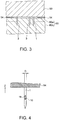
- Fig. 3 is a schematic side sectional view for explaining the first electrode needle 1 to the third electrode needle 3.
- a corium (a skin tissue 60a) is disposed under a skin.
- a subcutaneous tissue 60b is disposed under the skin tissue 60a.
- the thickness of the skin tissue 60a is approximately 2 mm.
- the length of the first electrode needle 1 to the third electrode needle 3 is approximately 5 mm.
- the first electrode needle 1 to the third electrode needle 3 have a columnar shape circular in section.
- the distal ends of the first electrode needle 1 to the third electrode needle 3 are pointed in a conical shape.
- the first electrode needle 1 to the third electrode needle 3 piece through parts of a skin surface 60c respectively corresponding thereto to be inserted (punctured) into the subject 60.
- the first electrode needle 1 to the third electrode needle 3 penetrate through the skin tissue 60a and reaches the subcutaneous tissue 60b. Note that interstitial fluid is filled in the subcutaneous tissue 60b.
- a detection film 10 is set on the surface of the first electrode needle 1.
- the detection film 10 functions as a working electrode that reacts with the interstitial fluid.
- the second electrode needle 2 functions as a counter electrode.
- the third electrode needle 3 functions as a reference electrode.
- the first electrode needle 1 to the third electrode needle 3 configure an electrode that detects an electric current flowing in the interstitial fluid.
- the first electrode needle 1 and the second electrode needle 2 detect an electric current generated by the reaction.
- films of protein or the like are formed on the surfaces of the electrode needles, the films cause electric resistance.
- the third electrode needle 3 is an electrode for detecting an increase in the electric resistance due to the films.
- Fig. 4 is a general side view schematically showing the first electrode needle 1.
- the first electrode needle 1 has a columnar shape circular in section and is pointed at a distal end portion.
- a surface section 1b explained below is formed from the center toward the distal end side.
- the detection film 10 is set on the surface section 1b.
- a major diameter D of the first electrode needle 1 is 0.1 mm or more.
- the major diameter indicates a diameter of a place where the diameter is the largest in the sectional shape of the first electrode needle 1.
- the major diameter D of the first electrode needle 1 is 0.5 mm or less.
- the first electrode needle 1 of the measuring device 50 can be formed as an electrode that is less easily broken and prevents the subject 60 from easily feeling pain.
- the major diameter D of the first electrode needle 1 is desirably 0.15 mm or more and 0.25 mm or less.
- the first electrode needle 1 can be formed as an electrode that is much less easily broken and prevents the subject 60 from more easily feeling pain.
- the major diameters of the second electrode needle 2 and the third electrode needle 3 are set the same as the major diameter D of the first electrode needle 1.
- Fig. 5A is a sectional view schematically showing the cross section of the first electrode needle 1.
- Fig. 5B is a sectional view schematically showing the cross section of the second electrode needle 2 and the third electrode needle 3. Note that Fig. 5B shows the second electrode needle 2 as an example.
- a core section 1a of the first electrode needle 1 As the material of a core section 1a of the first electrode needle 1, in this embodiment, stainless steel (SUS), which is metal having a circular shape in section, is used. As shown in Fig. 5A , in the core section 1a functioning as a base material of an electrode needle formed in a columnar shape, the surface section 1b obtained by shaving a part of a side surface is formed. The detection film 10 is set on the surface section 1b. Note that, since the core section 1a is made of stainless steel having electric conductivity, a first insulating film 11 is formed on the side surface. An electrode layer 12 is formed on the outer surface of the first insulating film 11.
- SUS stainless steel
- a second insulating film 13 covered with an insulating material is formed on side surfaces other than the surface section 1b on the outer surface of the electrode layer 12.
- the second insulating film 13 corresponds to an insulating section 14 in which an electrode (the electrode layer 12) is covered with the insulating material. Consequently, in the region of the surface section 1b, an electrode window section 15 in which the electrode (the electrode layer 12) is exposed to the outside is formed.
- platinum (Pt) plating is applied as the electrode layer 12, in this embodiment.
- gold (Au) plating may be applied.
- the detection film 10 is formed on the electrode window section 15. Details concerning the detection film 10 are explained below.
- the material of a core section 2a of the second electrode needle 2 is stainless steel.
- a first insulating film 21 is formed on the core section 2a.
- an electrode layer 22 is formed on the outer surface of the first insulating film 21.
- a region 2b having predetermined width W around the core section 2a is exposed and a region other than the region 2b is covered with the insulating material, whereby a second insulating film 23 is formed.
- the second insulating film 23 corresponds to an insulating section 24 in which an electrode (the electrode layer 22) is covered with the insulating material.
- an electrode window section 25 in which the electrode (the electrode layer 22) is exposed to the outside is formed in the region 2b.
- platinum (Pt) plating is applied as the electrode layer 22, in this embodiment.
- gold (Au) plating may be applied as the electrode layer 22, in this embodiment.
- the platinum has high stability and less easily reacts with the interstitial fluid and oxygen to be deteriorated. Therefore, the second electrode needle 2 can stably function for a long period.
- the third electrode needle 3 is configured the same as the second electrode needle 2.
- platinum (Pt) plating is applied as an electrode layer of the third electrode needle 3.
- the electrode layer may be an electrode layer obtained by stacking silver (Ag) film on platinum. Note that, when the silver (Ag) film is tacked on the platinum, the silver reversibly transitions to forms of silver and a silver ion in the interstitial fluid. Therefore, when this reaction is used, the silver is suitable for detection of film formation on the surface of the third electrode needle 3.
- the third electrode needle 3 functions as a reference electrode for detecting glucose using an enzyme. The silver surface is more desirably converted into AgCl.
- the stainless steel is used in this embodiment.
- metal other than the stainless steel, hard resin, an alloy, ceramics, or the like may be used. Note that, if the material is the metal or the alloy, the major diameters can be set small compared with when the material is the hard resin, the ceramics, or the like.
- the measuring device 50 continuously performs detection of glucose in the interstitial fluid.
- the measuring device 50 can be used in a CGMS (Continuous Glucose Monitoring System) that continuously observes a glucose value in the interstitial fluid.
- CGMS Continuous Glucose Monitoring System
- the detection film 10 includes an enzyme such as glucose oxidase.
- enzyme reaction indicated by Formula (1) is caused by the enzyme.
- Hydrogen peroxide is generated by the enzyme reaction.
- a voltage is applied to the hydrogen peroxide to electrolyze the hydrogen peroxide.
- the voltage is not particularly limited and only has to be determined by an experiment. In this embodiment, for example, a voltage of 0.6 V is applied.
- Reaction indicated by Formula (2) is caused in the first electrode needle 1 by the electrolysis.
- Reaction indicated by Formula (3) is caused in the second electrode needle 2 by the electrolysis.
- H 2 O 2 ⁇ O 2 + H 2 + + 2e - (2) 2H + + 1/2O 2 + 2e - ⁇ H 2 O (3)
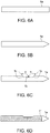
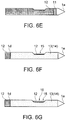
- Figs. 6A to 6G are general side views schematically showing a manufacturing method for an electrode needle.
- Fig. 7 is a general sectional view schematically showing the structure of the detection film 10 formed on the surface section 1b of the first electrode needle 1. The manufacturing method for an electrode needle is explained with reference to the first electrode needle 1 as an example.
- a stainless steel bar to be formed as the core section 1a is prepared.
- a polishing step shown in Fig. 6B the distal end portion of the stainless steel bar is polished into a conical shape. The distal end portion is pointed at an acute angle.
- a cutting step shown in Fig. 6C the side surface of the core section 1a is shaved to form the surface section 1b to be formed as a flat surface. Note that, in this case, for example, a cutting blade is rotated to be orthogonal to the longitudinal direction of the core section 1a (a puncturing direction in which the electrode needle is punctured) to cut the core section 1a. Consequently, the surface section 1b is formed in a rectangular shape.
- the surface section 1b is cut to be tapered to form inclined surface sections 1c respectively expanding to the outer side in regions of steps extending from end portions (both end portions) in the longitudinal direction of the surface section 1b to side surfaces on both sides of the surface section 1b.
- Both of angles ⁇ formed by the surface section 1b and the inclined surface sections 1c are set to approximately 135° in this embodiment. Note that the angles ⁇ may be set as appropriate between 90° or more and 170° or less.
- the core section 1a includes the inclined surface sections 1c inclining toward the electrode window section 15 explained below.
- the angles formed by the electrode window section 15 and the inclined surface sections 1c are 90° or more and 170° or less.
- the core section 1a includes the inclined surface sections 1c, compared with when the inclined surface sections 1c are formed at less than 90°, it is possible to reduce resistance when the first electrode needle 1 is punctured into the skin surface 60c. Therefore, it is possible to prevent the subject 60 from easily feeling pain.
- the first insulating film 11 is formed on the side surface (including the surface section 1b and the inclined surface sections 1c) of the core section 1a excluding a needle tip.
- the first insulating film 11 is a film that insulates the core section 1a and the electrode layer 12 explained below.
- synthetic resin is used as the insulating material.
- the insulating material may be a ceramics material.
- thermoplastic resin such as polyamide (PA), polybutylene terephthalate (PBT), polycarbonate (PC), polypropylene (PP), polyamide-imide (PAI), polyimide (PI), polyethylene terephthalate (PET), and polyvinyl chloride (PVC) and thermosetting resin such as epoxy resin (EP), polyurethane (PUR), and unsaturated polyester (UP)
- PA polyamide
- PBT polybutylene terephthalate
- PC polypropylene
- PAI polyamide-imide
- PI polyimide
- PET polyethylene terephthalate
- PVC polyvinyl chloride
- thermosetting resin such as epoxy resin (EP), polyurethane (PUR), and unsaturated polyester (UP)
- An insulating film functioning as the first insulating film 11 may be formed by subjecting stainless steel to alumina treatment.
- the insulating film functioning as the first insulating film 11 may be formed by performing heat treatment using special stainless steel (KCF).
- the electrode layer 12 which is a conductive layer to be formed as a wire, is formed on the outer surface (the surface section 1b and the inclined surface sections 1c) of the first insulting film 11.
- the electrode layer 12 functions as a wire that causes the detection film 10 and a control section of the measuring device 50 to electrically conduct.
- the electrode layer 12 of platinum is formed by electroless platinum plating. Electrolytic platinum plating may be used.
- the second insulating film 13 is formed on the outer surface of the electrode layer 12 excluding a connect section 1d electrically conducted to the needle tip, the surface section 1b, and the measuring device 50.
- the second insulating film 13 is also formed on the outer surface of the electrode layer 12 of the inclined surface sections 1c.
- the second insulating film 13 corresponds to the insulating section 14. Consequently, the electrode window section 15 in which the electrode layer 12 is exposed is formed.
- the insulating section 14 can be considered as including the inclined surface sections 1c inclining toward the electrode window section 15.
- Teflon registered trademark
- synthetic resin same as the synthetic resin of the first insulating film 11 can be used as the insulating material.
- Teflon (registered trademark) work is performed to form a film of Teflon (fluororesin) .
- Teflon registered trademark
- the Teflon in the second insulating film 13 it is possible to provide, in the first electrode needle 1, characteristics such as chemical resistance, a low elution property, non-adhesiveness, electric insulation, and abrasion resistance of the Teflon.
- the Teflon has an extremely low coefficient of friction, it is possible to reduce resistance even when the first electrode needle 1 is punctured into the skin surface 60c and when the first electrode needle 1 is pulled out from the skin surface 60c. Therefore, it is possible to prevent the subject 60 from easily feeling pain.
- the second insulating film 13 (the insulating section 14) is formed in regions corresponding to the inclined surface sections 1c.
- the second insulating film 13 does not have to be formed in the regions corresponding to the inclined surface sections 1c.
- the outer circumferential section of the surface section 1b and the regions of the inclined surface sections 1c may be, for example, covered with a partition wall layer 16.
- the detection film 10 is formed on the surface section 1b (the upper surface of the exposed electrode layer 12).
- the detection film 10 is explained with reference to Fig. 7 .
- the detection film 10 is configured by the electrode layer 12, the partition wall layer 16, and a sensing layer 17.
- an enzyme electrode layer is set on the upper surface of the electrode layer 12.
- the exposed electrode layer 12 functions as the enzyme electrode layer.
- the partition wall layer 16 is set on the upper surface of the electrode layer 12 and in the region of the electrode layer 12 corresponding to the outer circumferential section of the surface section 1b.
- the partition wall layer 16 is formed in a state in which the inner side thereof is opened.
- the electrode layer 12 functioning as the enzyme electrode layer is exposed on the opened inner side.
- the sensing layer 17 is set over the opened electrode layer 12 and the partition wall layer 16.
- the sensing layer 17 is stacked on the electrode layer 12 on the inner side of the partition wall layer 16.
- the sensing layer 17 is formed by four layers.
- a noise removing layer 17A a sensing layer for sensing information in an organism
- a detection layer 17B functioning as an enzyme layer a protection layer 17C, and an adjustment layer 17D are stacked in this order from the electrode layer 12 side.
- the partition wall layer 16 is set in order to improve adhesion of the enzyme electrode layer (the electrode layer 12) and the sensing layer 17.
- the sensing layer 17 has a hydrophilic nature and absorbs the interstitial fluid to swell.
- the swelled sensing layer 17 easily peels from the electrode layer 12.
- the partition wall layer 16 only has to be made of a material from which the swelled sensing layer 17 less easily peels.
- the material of the partition wall layer 16 is not particularly limited. As the material of the partition wall layer 16, for example, polyimide and acrylic can be used.
- the noise removing layer 17A prevents compounds of acetaminophen, ascorbic acid, uric acid, and the like from permeating through the detection film 10 to reach the enzyme electrode layer.
- the compounds of acetaminophen, ascorbic acid, uric acid, and the like are likely to be included in the interstitial fluid.
- the material of the noise removing layer 17A is not particularly limited. However, methylcellulose, acetylcellulose (cellulose acetate), polyvinylpyrrolidone, polyvinyl alcohol, and the like can be used.
- the detection layer 17B is a layer containing an enzyme.
- the detection layer 17B includes the enzyme, resin including the enzyme, a binder or a hardener, and albumin for protecting and stabilizing the enzyme.
- the enzyme includes glucose oxidase.
- the glucose oxidase facilitates the enzyme reaction indicated by Formula (1) above.
- the protection layer 17C protects an upper interface of the detection layer 17B.
- the material of the protection layer 17C is not particularly limited. However, methylcellulose, acetylcellulose (cellulose acetate), polyvinylpyrrolidone, polyvinyl alcohol, polyvinyl alcohol-polyvinyl acetate copolymer, and the like can be used alone or in combination. Further, albumin is desirably contained in the material of the protection layer 17C.
- the adjustment layer 17D prevents blood, interstitial fluid, and the like, which are measurement targets, from coming into direct contact with the detection layer 17B.
- the adjustment layer 17D has a function of causing a part of oxygen and glucose to permeate and controlling permeability of the oxygen and the glucose.
- the adjustment layer 17D desirably causes the oxygen to permeate more than the glucose.
- the enzyme reaction changes to a saturated state. In this state, a glucose value cannot be detected. Therefore, the adjustment layer 17D controls the permeability of the glucose and suppresses the enzyme reaction from changing to the saturated state even when measurement target glucose concentration is high.
- the material of the adjustment layer 17D only has to be capable of controlling the permeability of the oxygen and the glucose and is not particularly limited.
- a material formed by generating urethane bond and constructing a bridge structure using a crosslinking agent such as an isocyanate compound and polyethylene glycol of polymer of a terminal hydroxyl group, acrylic acid 4-hydroxybutyl, or the like alone or as a mixture can be used.
- the first electrode needle 1 is formed through the steps explained above.
- Fig. 8 is a block diagram schematically showing a circuit configuration of the measuring device 50.
- the measuring device 50 includes a current detection circuit 56 functioning as a current detecting section.
- the first electrode needle 1, the second electrode needle 2, and the third electrode needle 3 are connected to the current detection circuit 56.
- the current detection circuit 56 is further connected to an A/D (Analog/Digital) conversion circuit 57.
- the current detecting circuit 56 detects, according to an instruction of a measurement control section 55, an electric current flowing between the first electrode needle 1 (the detection film 10) and the second electrode needle 2.
- the current detection circuit 56 converts the electric current into a voltage and outputs the voltage to the A/D conversion circuit 57.
- the electric current flowing between the detection film 10 and the second electrode needle 2 has a correlation with a glucose value. Therefore, the voltage output to the A/D conversion circuit 57 has a correlation with the glucose value.
- the A/D conversion circuit 57 converts the voltage into a numerical value.
- the A/D conversion circuit 57 outputs data of the voltage converted into the numerical value to the measurement control section 55 having a function of a computing section.
- the measurement control section 55 converts the input voltage data into a glucose value.
- the measurement control section 55 has stored therein data of a correlation table indicating a relation between the voltage data and the glucose value.
- the measurement control section 55 computes the glucose value using the correlation table and the voltage data.
- the measurement control section 55 outputs the computed glucose value to the display section 51.
- the display section 51 displays the glucose value. Further, the measurement control section 55 has stored therein data of a determination value.
- the measurement control section 55 compares the determination value and the glucose value and determines whether the glucose value is a value within a normal range or in an abnormal state. When determining that the glucose value is an abnormal value, the measurement control section 55 outputs information indicating the abnormal state to the display section 51 and the speaker 53.
- the display section 51 displays a warning sentence or the like.
- the speaker 53 emits warning sound.
- the operator operates the input sections 52 to input an instruction for a measurement start, a measurement stop, or the like to the measurement control section 55.
- the measurement control section 55 drives the measuring device 50 according to the instruction of the operator.
- a battery 58 is set in the measuring device 50.
- the battery 58 supplies electric power to the other components including the measurement control section 55. Consequently, the measuring device 50 can be set in the subject 60 and driven without being connected to an external power supply. Therefore, the subject 60 can easily move in a state in which the subject 60 wears and operates the measuring device 50.
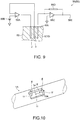
- Fig. 9 is a circuit diagram showing the configuration of the current detection circuit 56.
- the current detection circuit 56 shown in Fig. 9 is a circuit called potentiostat.
- the current detection circuit 56 includes a first operational amplifier 56A.
- a power supply 56B is connected to a plus input end of the first operational amplifier 56A.
- a predetermined voltage is applied to the plus input end of the first operational amplifier 56A.
- a voltage value is not particularly limited. However, in this embodiment, the voltage value is set to, for example, 0.6 V.
- the power supply 56B can be realized by dividing the voltage of the battery 58 and setting a voltage in a diode.
- the third electrode needle 3 is connected to a minus input end of the first operational amplifier 56A.
- the second electrode needle 2 is connected to an output end of the first operational amplifier 56A.
- the first operational amplifier 56A feeds an electric current the second electrode needle 2 such that potential from the third electrode needle 3 and potential given by the power supply 56B become the same potential.
- the first operational amplifier 56A acts such that an electric current does not flow to the third electrode needle 3.
- the current detection circuit 56 includes a second operational amplifier 56C. A plus input end of the second operational amplifier 56C is grounded. The detection film 10 is connected to a minus input end of the second operational amplifier 56C. The minus input end and an output end of the second operational amplifier 56C are connected via a resistor 56D. An output terminal 56E of the current detection circuit 56 is connected to the output end of the second operational amplifier 56C.
- the plus input end and the minus input end have the same potential. Therefore, the potential of the detection film 10 is 0 V. Potential of 0.6 V is generated between the third electrode needle 3 and the detection film 10. In the subject 60, the enzyme reaction indicated by Formula (1) to Formula (3) occurs. Therefore, an electric current flows between the second electrode needle 2 and the detection film 10. Since the second operational amplifier 56C has high input impedance, the electric current flows from the detection film 10 to the output end of the second operational amplifier 56C passing through the resistor 56D. Since a voltage drop occurs when the electric current flows to the resistor 56D, in the output terminal 56E, the electric current between the second electrode needle 2 and the detection film 10 is converted into a voltage and output.
- a not-shown compensation circuit is set in the current detection circuit 56.
- the compensation circuit detects resistance between the third electrode needle 3 and the detection film 10. The resistance increases when films are formed on the surfaces of the second electrode needle 2, the third electrode needle 3, and the detection film 10.
- the compensation circuit changes, according to the resistance between the third electrode needle 3 and the detection film 10, a voltage applied to the second electrode needle 2. Therefore, stable current measurement can be performed by the compensation circuit.
- Fig. 10 is a general perspective view schematically showing another example of a surface section according to a second embodiment.
- a surface section 1e of a first electrode needle 1A in this embodiment is different from the surface section 1b in the first electrode needle 1 in the first embodiment as explained below.
- the inclined surface sections 1c extending along the longitudinal direction (the puncturing direction) of the core section 1a are formed. Inclined surface sections extending along the latitudinal direction are not formed.
- inclines surface sections 1f are formed along the longitudinal direction and, in addition, the inclined surface sections 1f are formed along the latitudinal direction as well.
- Sections other than the surface section 1e are configured the same as the sections in the first embodiment. Therefore, on the surface section 1e including the inclined surface sections 1f, an electrode window section 15A is formed like the electrode window section 15 in the first embodiment. Note that angles ⁇ formed by the surface section 1e (the electrode window section 15A) and the inclined surface sections 1f are set to 90° or more and 170° or less as in the first embodiment. In this embodiment, specifically, the angles P are set to 135°.
- the first electrode needle 1A having such a configuration and a measuring device including the first electrode needle 1A, it is possible to achieve effects same as the effects (1) to (8) in the first embodiment.
- Another measuring device 70 functioning as a biological information measuring device is explained.
- Fig. 11 is a schematic perspective view of the measuring device 70 according to a third embodiment.
- Fig. 12 is a circuit diagram showing the configuration of a current detection circuit 71.
- This embodiment is different from the first embodiment in that the third electrode needle 3, which is the reference electrode, is omitted. Note that explanation is omitted concerning components same as the components in the first embodiment.
- the first electrode needle 1 and the second electrode needle 2 are set on a rear surface 70b.
- the first electrode needle 1 and the second electrode needle 2 are stuck into the skin of the subject 60 and used.
- the first electrode needle 1 and the second electrode needle 2 in this embodiment are configured the same as those in the first embodiment.
- the first electrode needle 1 functions as the working electrode and the second electrode needle 2 functions as the counter electrode.
- the measuring device 70 includes the current detection circuit 71 functioning as the current detecting section.
- the current detection circuit 71 is a circuit that measures an electric current flowing between the second electrode needle 2 and the detection film 10.
- the current detection circuit 71 includes an operational amplifier 71A. A plus input end of the operational amplifier 71A is grounded.
- the detection film 10 is connected to a minus input end of the operational amplifier 71A.
- the minus input end and an output end of the operational amplifier 71A are connected via a resistor 71B.
- An output terminal 71C of the current detection circuit 71 is connected to the output end of the operational amplifier 71A.
- the second electrode needle 2 is connected to the power supply 56B.
- the enzyme reaction indicated by Formula (1) to Formula (3) occurs. Therefore, an electric current flows between the second electrode needle 2 and the detection film 10.
- the electric current flowing between the second electrode needle 2 and the detection film 10 is input to the output end of the operational amplifier 71A passing through the resistor 71B.
- the electric current input to the output end flows from the ground to the second electrode needle 2.
- the voltage at the minus input terminal of the operational amplifier 71A is 0 V.
- the voltage at the output terminal 71C is, according to a voltage drop of the resistor 71B, a value obtained by multiplying together a resistance value of the resistor 71B and a value of the electric current flowing in the resistor 71B.
- the electric current flowing between the second electrode needle 2 and the detection film 10 is equal to the electric current flowing in the resistor 71B. Therefore, by measuring the voltage at the output terminal 71C, it is possible to measure the electric current flowing between the second electrode needle 2 and the detection film 10.
- the second electrode needle 2 is equivalent to the counter electrode and the detection film 10 is equivalent to the working electrode. Therefore, by measuring the voltage at the output terminal 71C, it is possible to measure a glucose value of the subject 60.
- the measuring device 70 in this embodiment includes the first electrode needle 1 and the second electrode needle 2. It is possible to measure biological information (a glucose value) by detecting, with the current detection circuit 71, an electric current between the first electrode needle 1 and the second electrode needle 2. Since the first electrode needle 1 and the second electrode needle 2 are configured as in the first embodiment, even if the first electrode needle 1 and the second electrode needle 2 are punctured, it is possible to measure the glucose value without stimulating the pain spot of the subject 60. Therefore, the measuring device 70 in this embodiment can measure the biological information (the glucose value) while causing a patient to less easily feel pain even if the first electrode needle 1 and the second electrode needle 2 are punctured.
- An insulin supply device 80 functioning as a liquid supply device is explained.
- the measuring device 50 explained in the first embodiment is used. Note that explanation is omitted concerning components same as the components in the first embodiment.
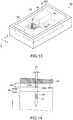
- Fig. 13 is a general perspective view schematically showing the structure of the insulin supply device 80 according to the fourth embodiment. Specifically, Fig. 13 is a diagram of the insulin supply device 80 viewed from the rear side.
- a first electrode needle 100 functioning as an injection needle and a working electrode, the second electrode needle 2, and the third electrode needle 3 are set.
- a tank 81 that stores insulin serving as liquid is set on the inside of the insulin supply device 80. Further, on the inside of the insulin supply device 80, a pump 82 that feeds the insulin stored in the tank 81 to the first electrode needle 100 is set. The pump 82 and the first electrode needle 100 are coupled by a tube 83 for transportation. Besides, on the inside of the insulin supply device 80, the battery 58, a circuit board 85, and the like are set.
- the tank 81 includes a bag made of resin on the inside.
- the insulin is stored in the inside of the bag.
- the bag is deformed when the insulin in the tank 81 decreases. Consequently, it is possible to store the insulin while preventing the insulin from coming into contact with the air.
- the pump 82 is desirably a volume pump that can manage a transportation amount. A gear pump, a screw pump, a vane pump, and the like can be used.
- On the circuit board 85 a circuit that controls the pump 82 and a circuit that measures a glucose value as in the first embodiment are set.
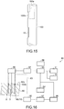
- Fig. 14 is a general side view schematically showing the structure of the first electrode needle 100.
- Fig. 15 is a main part side view schematically showing the structure of the first electrode needle 100.
- the first electrode needle 100 is formed the same as the first electrode needle 1 in the first embodiment.
- a major diameter D1 of the first electrode needle 100 is 0.1 mm or more and 0.5 mm or less. Therefore, the electrode needle 100 of the insulin supply device 80 is less easily broken and can prevent the subject 60 from easily feeling pain.
- the detection film 10 is set as in the first embodiment.
- the first electrode needle 100 is different from the first embodiment in that, on the inside of the first electrode needle 100, a hole section 100a is set as a channel solid at a distal end formed from the rear end face of the first electrode needle 100 toward the distal end portion along the center axis of the first electrode needle 100.
- the hole section 100a is connected to an opening section 100b functioning as a lateral hole formed to be opened in a part between the rear end face of the first electrode needle 100 and the detection film 10.
- the insulin flows out from the tank 81, circulates through the pump 82, the tube 83, and the hole section 100a functioning as the channel of the first electrode needle 100 in this order, and is discharged to the subject 60 from the opening section 100b of the first electrode needle 100.
- a distance 100c between the center of the opening section 100b and the rear surface 80b is set in a range of 1 mm or more and 2 mm or less.
- the opening section 100b is located in the skin tissue 60a, it is possible to supply the insulin to the skin tissue 60a.
- the detection film 10 is located in the subcutaneous tissue 60b, it is possible to measure a glucose value in the subcutaneous tissue 60b.
- the interstitial fluid is present more in the subcutaneous tissue 60b compared with the skin tissue 60a.
- the detection film 10 more often comes into contact with the glucose when the detection film 10 is located in a place where the interstitial fluid is present more. Therefore, compared with when the detection film 10 is located in the skin tissue 60a, it is possible to more accurately measure a glucose value when the detection film 10 is located in the subcutaneous tissue 60b compared with when the detection film 10 is located in the skin tissue 60a.
- Fig. 16 is a block diagram schematically showing a circuit configuration of the insulin supply device 80.
- the measuring control section 55 having the function of the computing section, the current detection circuit 56, the A/D conversion circuit 57, the display section 51, the input sections 52, and the speaker 53 are provided as in the first embodiment.
- a supply-amount control section 86 that controls a supply amount of the insulin and a pump driving section 87 that drives the pump 82 are provided.
- the supply-amount control section 86 is connected to the measurement control section 55 and further connected to the pump driving section 87.
- the pump driving section 87 is connected to the pump 82.
- the first electrode needle 100, the second electrode needle 2, and the third electrode needle 3 piece through parts respectively corresponding thereto on the skin surface 60c to be inserted (punctured) into the subject 60.
- the measurement control section 55 computes the measured glucose value and compares the glucose value with the determination value. When determining that the glucose value is in an abnormal state, the measurement control section 55 outputs an instruction signal for discharging the insulin and data of the glucose value to the supply-amount control section 86.
- the supply-amount control section 86 computes an amount of the insulin supplied to the subject 60.
- the supply-amount control section 86 includes a supply amount table indicating a relation between the glucose value and the amount of the insulin to be supplied.
- the supply-amount control section 86 computes the amount of the insulin to be applied with reference to the glucose value and the supply amount table.
- the supply-amount control section 86 computes, from the amount of the insulin to be supplied, time in which the pump 82 is driven. An amount of the insulin to be supplied per unit time is set in the pump 82.
- the supply-amount control section 86 outputs, to the pump driving section 87, data of the time in which the pump 82 is driven and an instruction signal for driving the pump 82.
- the pump driving section 87 drives the pump 82 according to the instruction signal.
- the pump 82 supplies a designated amount of the insulin to the subject 60.
- the hole section 100a functioning as the channel for circulating the liquid (the insulin) to the core section and the opening section 100b connected to the hole section 100a are set. Consequently, it is possible to not only measure an amount of the glucose in the organism but also include a function of the injection needle that supplies the insulin into the organism.
- the insulin supply device 80 functioning as the liquid supply device in this embodiment includes the biological-information measuring device (the measuring device 50) in the first embodiment, the first electrode needle 100 including the hole section 100a functioning as the channel, the second electrode needle 2, and the third electrode needle 3. Consequently, it is possible to realize the insulin supply device 80 that prevents a patient from easily feeling pain. Besides, it is possible to achieve simplification of the insulin supply device 80. It is possible to improve convenience.
- An insulin supply device 90 which is another example of the liquid supply device, is explained.
- Fig. 17 is a block diagram schematically showing a circuit configuration of the insulin supply device 90 according to a fifth embodiment.
- the insulin supply device 90 in this embodiment is different from the insulin supply device 80 in the fourth embodiment as explained below.
- the hole section 100a functioning as the channel and the opening section 100b are formed in the first electrode needle 100.
- a hole section functioning as a channel and an opening section 200a are formed in a second electrode needle (a second electrode needle 200) functioning as a counter electrode.
- the insulin supply device 90 functioning as the liquid supply device includes the second electrode needle (the second electrode needle 200) functioning as the counter electrode.
- a hole section functioning as a channel is set on the inside of the second electrode needle 200.
- the hole section is connected to the opening section 200a set on the side surface of the second electrode needle 200.
- the tube 83 is connected to the hole section of the second electrode needle 200.
- Other circuit components are the same as those in the fourth embodiment.
- the insulin flows out from the tank 81 and is supplied from the opening section 200a of the second electrode needle 200 to the subject 60 passing through the pump 82, the tube 83, and the hole section inside the second electrode needle 200.
- the detection film 10 reacts with the glucose, an electric current flows between the detection film 10 and the second electrode needle 200.
- the current detection circuit 56 can detect a glucose value in the interstitial fluid by detecting an electric current.
- the measurement control section 55 determines that the glucose value in the subject 60 is in an abnormal state
- the supply-amount control section 86 supplies the insulin from the opening section 200a of the second electrode needle 200 to the subject 60.
- the hole section (the opening section 200a) functioning as the channel for circulating the liquid (the insulin) is set in the core section. Consequently, it is possible to not only measure an amount of glucose in an organism but also include a function of an injection needle that supplies the insulin into the organism.
- the insulin supply device 90 functioning as the liquid supply device in this embodiment includes the biological information measuring device (the measuring device 50) in the first embodiment, the first electrode needle 1 functioning as the working electrode, the second electrode needle 200 functioning as the counter electrode including the hole section functioning as the channel and the opening section 200a, and the third electrode needle 3 functioning as the reference electrode. Consequently, the insulin supply device 90 does not need to separately include an injection needle. Therefore, it is possible to realize the insulin supply device 90 that prevents a patient from easily feeling pain. Besides, it is possible to achieve simplification of the insulin supply device 90. It is possible to improve convenience.
- An insulin supply device 91 which is another example of the liquid supply device, is explained.
- Fig. 18 is a block diagram schematically showing a circuit configuration of the insulin supply device 91 according to a sixth embodiment.
- the insulin supply device 91 in this embodiment is different from the insulin supply device 90 in the fifth embodiment as explained below.
- the hole section functioning as the channel and the opening section 200a are formed in the second electrode needle 200.
- a hole section functioning as a channel and an opening section 300a are formed in a third electrode needle (a third electrode needle 300) functioning as a reference electrode.
- the insulin supply device 91 functioning as the liquid supply device includes the third electrode needle (the third electrode needle 300) functioning as the reference electrode.
- a hole section functioning as a channel is set on the inside of the third electrode needle 300.
- the hole section is connected to the opening section 300a set on the side surface of the third electrode needle 300.
- the tube 83 is connected to the hole section of the third electrode needle 300.
- Other circuit components are the same as those in the fifth embodiment.
- the insulin flows out from the tank 81 and is supplied from the opening section 300a of the third electrode needle 300 to the subject 60 passing through the pump 82, the tube 83, and the hole section on the inside of the third electrode needle 300.
- the current detection circuit 56 can detect a glucose value in the interstitial fluid by detecting an electric current.
- the measurement control section 55 determines that the glucose value in the subject 60 is in an abnormal state
- the supply-amount control section 86 supplies the insulin from the opening section 300a of the third electrode needle 300 to the subject 60.
- the hole section (the opening section 300a) functioning as the channel for circulating the liquid (the insulin) is set in the core section. Consequently, it is possible to not only measure an amount of glucose in an organism but also include a function of an injection needle that supplies the insulin into the organism.
- the insulin supply device 91 functioning as the liquid supply device in this embodiment includes the biological information measuring device (the measuring device 50) in the first embodiment, the first electrode needle 1 functioning as the working electrode, the second electrode needle 2 functioning as the counter electrode, and the third electrode needle 300 functioning as the reference electrode including the hole section functioning as the channel and the opening section 300a. Consequently, the insulin supply device 91 does not need to separately include an injection needle. Therefore, it is possible to realize the insulin supply device 91 that prevents a patient from easily feeling pain. Besides, it is possible to achieve simplification of the insulin supply device 91. It is possible to improve convenience.
- An insulin supply device 92 which is another example of the liquid supply device, is explained.
- Fig. 19 is a schematic perspective view showing the structure of the insulin supply device 92 according to a seventh embodiment and is a view of the insulin supply device 92 functioning as the liquid supply device viewed from the rear side.
- Fig. 20 is a side sectional view schematically showing the structure of a first electrode needle 401 to a third electrode needle 403 and is a view of the first electrode needle 401 to the third electrode needle 403 punctured into the subject 60.
- the insulin supply device 92 in this embodiment is different from the insulin supply device 80 in the fourth embodiment in that the first electrode needle 401 to the third electrode needle 403 are punctured obliquely to the surface of a skin. Note that explanation is omitted concerning components same as the components in the fourth embodiment.
- a first electrode needle (the first electrode needle 401) functioning as an injection needle and a working electrode
- a second electrode needle (the second electrode needle 402) functioning as a counter electrode
- a third electrode needle (the third electrode needle 403) functioning as a reference electrode
- the first electrode needle 401, the second electrode needle 402, and the third electrode needle 403 are set obliquely to a rear surface 92b and set in parallel to one another.
- a major diameter D2 of the first electrode needle 401 is 0.1 mm or more and 0.5 mm or less. Therefore, the first electrode needle 401 of the insulin supply device 92 is less easily broken and can prevent the subject 60 from easily feeling pain.
- the detection film 10 is set from the center toward the distal end side.
- a hole section 401a is set on the inside of the first electrode needle 401. The hole section 401a is connected to an opening section 401b functioning as a hole section located between the base of the first electrode needle 401 and the detection film 10.
- a distance 401c between the center of the opening section 401b and the rear surface 92b is set in a range of 1 mm or more and 2 mm or less.
- the opening section 401b is located in the skin tissue 60a, it is possible to supply the insulin to the skin tissue 60a. It is possible to measure a glucose value in the subcutaneous tissue 60b.
- the interstitial fluid is present more in the subcutaneous tissue 60b than in the skin tissue 60a.
- the detection film 10 more often comes into contact with the glucose in a place where the interstitial fluid is present more. Therefore, it is possible to accurately measure the glucose value.
- a major diameter of the second electrode needle 402 and the third electrode needle 403 is 0.1 mm or more and 0.5 mm or less. Therefore, the second electrode needle 402 and the third electrode needle 403 of the insulin supply device 92 are less easily broken and can prevent the subject 60 from easily feeling pain.
- the first electrode needle 401, the second electrode needle 402, and the third electrode needle 403 are obliquely inserted into the subject 60. Consequently, when force in the normal direction of the rear surface 92b acts on the insulin supply device 92, the direction of the force and the longitudinal direction of the needles cross. Therefore, the skin tissue 60a acts such that the first electrode needle 401, the second electrode needle 402, and the third electrode needle 403 do not come off. As a result, even when external force is applied to the insulin supply device 92, it is possible to prevent the insulin supply device 92 from being easily separated from the subject 60.
- a part of the core section 1a includes the surface section 1b to form the electrode window 15.
- the region 2b having the predetermined width W is exposed around the core section 2a to form the electrode window section 25.
- a surface section same as the surface section 1b may be provided in the core section 2a of the second electrode needle 2 to form the electrode window section 25. This is the same in the third electrode needle 3.
- the three electrode needles are used. However, only the first electrode needle 100 functioning as the working electrode and the second electrode needle 2 functioning as the counter electrode may be used without using the third electrode needle 3 functioning as the reference electrode.
- the insulin supply device 90 in the fifth embodiment only the first electrode needle 1 and the second electrode needle 200 may be used.
- the insulin supply device 92 in the seventh embodiment only the first electrode needle 401 and the second electrode needle 402 may be used.
- the insulin supply devices the liquid supply devices
- the first electrode needle 100 functions as the injection needle.
- the second electrode needle 200 functions as the injection needle.
- the third electrode needle 300 functions as the injection needle.
- the injection needle is not limited to this. At least two or three of the first electrode needle, the second electrode needle, and the third electrode needle may function as injection needles.
- the electrode needles configured as the injection needles may be connected to the tube 83.
- the insulin circulating in the tube 83 according to the driving of the pump 82 can circulate through a channel of the electrode needles functioning as the injection needles to be discharged from the opening section.
- Such a configuration effectively functions, for example, when an amount of the insulin discharged from the injection needles is smaller than an amount necessary in unit time.
- the configuration is particularly effective when needles have a small major diameter (the needles are thin electrode needles) and a discharge amount per one needle is limited. Note that, by adopting such a configuration, it is possible to expand an adjustment range of a supply amount of the insulin while achieving a reduction in the diameter of the electrode needles in the insulin supply device.
- the electrode needles in the first embodiment basically include the main bodies circular in section.
- the shape of the main bodies is not limited to this.
- the sectional shape of the main bodies may be an elliptical shape. This is the same in the second and subsequent embodiments.
- the surface section 1b in the first electrode needle 1 in the first embodiment is the surface section substantially rectangular in plan view.
- the surface section 1b is not limited to this.
- the surface section 1b may be a surface section having a track shape (a shape in which any opposed sides of a rectangle are curved lines and linked to the remaining opposed sides).
- the inclined surface sections may be provided between the surface section (the electrode window section) and the core section.
- the core sections of the first electrode needle 1, the second electrode needle 2, and the third electrode needle 3 in the first embodiment are formed in the columnar shape.
- the core sections are not limited to this.
- the core sections may be formed in a tubular shape.
Landscapes
- Health & Medical Sciences (AREA)
- Life Sciences & Earth Sciences (AREA)
- Physics & Mathematics (AREA)
- Engineering & Computer Science (AREA)
- Public Health (AREA)
- Biomedical Technology (AREA)
- Heart & Thoracic Surgery (AREA)
- Veterinary Medicine (AREA)
- Animal Behavior & Ethology (AREA)
- General Health & Medical Sciences (AREA)
- Pathology (AREA)
- Medical Informatics (AREA)
- Surgery (AREA)
- Biophysics (AREA)
- Molecular Biology (AREA)
- Optics & Photonics (AREA)
- Chemical & Material Sciences (AREA)
- General Chemical & Material Sciences (AREA)
- Chemical Kinetics & Catalysis (AREA)
- Hematology (AREA)
- Emergency Medicine (AREA)
- Anesthesiology (AREA)
- Vascular Medicine (AREA)
- Dermatology (AREA)
- Bioinformatics & Cheminformatics (AREA)
- Medicinal Chemistry (AREA)
- Pharmacology & Pharmacy (AREA)
- Diabetes (AREA)
- Physiology (AREA)
- Pain & Pain Management (AREA)
- Measurement Of The Respiration, Hearing Ability, Form, And Blood Characteristics Of Living Organisms (AREA)
Abstract
An electrode needle (a first electrode needle) is an electrode needle punctured into an organism. The electrode needle includes a columnar or tubular core section, an electrode formed in the core section, an insulating section in which the electrode is covered with an insulating material, and an electrode window section in which the electrode or a sensing layer (a detection layer) formed on the electrode is exposed.
Description
- The present invention relates to an electrode needle, a biological information measuring device, and a liquid supply device.
- A diabetic having abnormal insulin secretion from the pancreas, in particular, no insulin secretion performs blood sampling, for example, four times in one day before meals and before bedtime and measures blood sugar levels. When a blood sugar level is high, the diabetic performs insulin administration.
-
JP-T-2010-537732 -
JP-T-2005-520648 - In
Patent Literature 1, a cylindrical needle is used. A substrate is set in the needle. A plurality of electrodes are set on the substrate. After the needle is inserted into a skin tissue of a patient, the needle is pulled out leaving the substrate in the skin tissue. Since the substrate is set in the needle in this way, the external shape of the needle is large. Therefore, when the needle is inserted into the skin tissue, the needle easily gives pain to the patient. InPatent Literature 2, the insertion needle includes the smooth surface inclining toward the distal end and the elongated grove and inserts the subcutaneous insertion-type device into a skin tissue. However, the external shape of the insertion needle is large. Therefore, when the subcutaneous insertion-type device is inserted into the skin tissue, the subcutaneous insertion-type device easily gives pain to the patient. - Therefore, there is a demand for an electrode needle that highly accurately measures information in an organism and prevents a patient from easily feeling pain when the needle is inserted and when the needle is pulled out, a biological information measuring device including the electrode needle, and a liquid supply device.
- An advantage of some aspects of the invention is to solve at least a part of the problems, and the invention can be implemented as the following forms or application examples.
- An electrode needle according to this application example is an electrode needle punctured into an organism, and including: a columnar or tubular core section; an electrode formed in the core section; an insulating section in which the electrode is covered with an insulating material; and an electrode window section in which the electrode or a sensing layer formed on the electrode is exposed.
- The electrode needle includes the core section, the electrode formed in the core section, the insulating section in which the electrode is covered with the insulating material, and the electrode window section in which the electrode or the sensing layer is exposed. Consequently, since a region other than the electrode window section is covered with the insulating section, when the electrode needle is punctured into the organism and used, it is possible reduce a loss of a voltage, noise, and the like and accurately detect, for example, an electric current. Consequently, it is possible to realize the electrode needle that can highly accurately measure information in the organism.
- In the electrode needle according to the application example, it is preferable that the electrode window section is exposed in a rectangular shape along a puncturing direction in which the electrode needle is punctured.
- With this electrode needle, since the electrode window section is exposed in the rectangular shape along the puncturing direction in which the electrode needle is punctured, it is possible to prevent peeling of the electrode, the sensing layer, and the like during the puncture.
- In the electrode needle according to the application example, it is preferable that the core section or the insulating section includes inclined surface sections inclining toward the electrode window section.
- With this electrode needle, since the core section or the insulating section includes the inclined surface sections inclining toward the electrode window section, it is possible to reduce resistance at the time when the electrode needle is inserted and pulled out. Therefore, it is possible to realize the electrode needle that prevents a patient from easily feeling pain.
- In the electrode needle according to the application example, it is preferable that the sensing layer senses information in the organism.
- With this electrode needle, the sensing layer can sense a predetermined component of the organism and feed an electric current.
- In the electrode needle according to the application example, it is preferable that a maj or diameter of the electrode needle is 0.1 mm or more and 0.5 mm or less.
- With this electrode needle, the major diameter of the electrode needle is 0.1 mm or more. Note that the major diameter indicates a diameter in a place where the diameter is the largest in a sectional shape of the electrode needle. In this case, since the electrode needle sticks into the skin without bending, it is possible to prevent the electrode needle from being easily broken. The major diameter of the electrode needle is 0.5 mm or less. In this case, since a stimulus of the electrode needle to a pain spot is small, it is possible to prevent a patient from easily feeling pain. Therefore, it is possible to realize the electrode needle that is less easily broken and prevents the patient from easily feeling pain.
- In the electrode needle according to the application example, it is preferable that angles formed by the electrode window section and the inclined surface sections are 90° or more and 170° or less.
- With this electrode needle, the angles formed by the electrode window section and the inclined surface sections are 90° or more and 170° or less. Therefore, it is possible to reduce resistance at the time when insertion and pull-out of the electrode needle is performed and smoothly perform the insertion and the pull-out.
- In the electrode needle according to the application example, it is preferable that the electrode needle includes a channel for circulating liquid.
- With this electrode needle, since the channel for circulating the liquid is provided, it is possible to not only measure the information in the organism but also include a function of an injection needle.
- A biological information measuring device according to this application example includes: a first electrode needle and a second electrode needle configured by the electrode needle according to any of the application examples; and a current detecting section configured to detect an electric current between the first electrode needle and the second electrode needle.
- The biological information measuring device includes the first electrode needle and the second electrode needle. By detecting, with the current detecting section, a value of the electric current between the first electrode needle and the second electrode needle, it is possible to measure biological information. Note that the first electrode needle and the second electrode needle are respectively inserted into different parts. Therefore, compared with when a needle including a substrate on which the first electrode and the second electrode are set as in the configuration in the past is used, it is possible to reduce a major diameter of the first electrode needle and the second electrode needle inserted into the skin. Note that, as the major diameter is smaller, a pain spot of the skin is less easily stimulated. Therefore, in the biological information measuring device in this application example, even if the first electrode needle and the second electrode needle are inserted into or pulled out from the abdomen or the like of a patient in order to measure information in the organism, it is possible to prevent the patient from easily feeling pain.
- In the biological information measuring device according to the application example, it is preferable that the information in the organism is information concerning glucose, the first electrode needle is a working electrode including a sensing layer including an enzyme layer, and the second electrode is a counter electrode that leads an electric current between the second electrode needle and the first electrode needle.
- With this biological information measuring device, since the first electrode needle is the working electrode including the sensing layer including the enzyme layer, the glucose reacts with the enzyme layer and generates an electric current. The second electrode needle is the counter electrode that leads an electric current between the second electrode needle and the first electrode needle. Note that, as glucose concentration is higher, the current value is larger because the reaction with the enzyme layer further advances. Therefore, it is possible to accurately detect the concentration of the glucose by analyzing the current value detected by the current detecting section.
- In the biological information measuring device according to the application example, it is preferable that the biological information measuring device includes a third electrode needle functioning as a reference electrode used for detection of resistance of an electric current flowing to the first electrode needle.
- The biological information measuring device includes the third electrode needle (the reference electrode) used for detection of resistance of an electric current flowing to the first electrode needle. Interstitial fluid is present in the organism. When a substance included in the interstitial fluid adheres to the surfaces of the first electrode needle and the second electrode needle and films are formed, resistance applied to an electric current flowing to the first electrode needle and the second electrode needle increases. Therefore, by detecting the resistance using the reference electrode, it is possible to improve measurement accuracy of the current value in the current detecting section.
- A liquid supply device according to this application example includes the biological information measuring device according to the application examples described above. The first electrode needle or the second electrode needle includes a channel for circulating liquid.
- The liquid supply device includes the biological information measuring device (the first electrode needle (the working electrode) and the second electrode needle (the counter electrode)). Therefore, it is possible to detect an electric current and measure information in an organism. Since the first electrode needle or the second electrode needle includes the channel for circulating liquid, the liquid supply device does not need to separately include an injection needle. It is possible to discharge the liquid from the channel. Therefore, it is possible to realize the liquid supply device that prevents a patient from easily feeling pain. Further, it is possible to achieve simplification of the liquid supply device. It is possible to improve convenience.
- A liquid supply device according to this application example includes the biological information measuring device according to the application examples described above. Any one of the first electrode needle, the second electrode needle, and the third electrode needle includes a channel for circulating liquid.
- The liquid supply device includes the biological information measuring device (the first electrode needle (the working electrode), the second electrode needle (the counter electrode), and the third electrode needle (the reference electrode)). Therefore, it is possible to detect an electric current and measure information in an organism. Since any one of the first electrode needle, the second electrode needle, and the third electrode needle includes the channel for circulating liquid, the liquid supply device does not need to separately include an injection needle. It is possible to discharge the liquid from the channel. Therefore, it is possible to realize the liquid supply device that prevents a patient from easily feeling pain. Further, it is possible to achieve simplification of the liquid supply device. It is possible to improve convenience.
- In the liquid supply device according to the application example, it is preferable that the information in the organism is information concerning glucose, and the liquid is insulin.
- The liquid supply device detects the glucose in the organism and supplies the insulin into the organism. Therefore, the liquid supply device can supply the insulin according to an amount of the glucose in the organism.
- The invention will be described with reference to the accompanying drawings, wherein like numbers reference like elements.
-
Fig. 1 is a schematic perspective view of a measuring device according to a first embodiment. -
Fig. 2 is a schematic perspective view of the measuring device. -
Fig. 3 is a schematic side sectional view for explaining a first electrode needle to a third electrode needle. -
Fig. 4 is a general side view schematically showing the first electrode needle. -
Fig. 5A is a sectional view schematically showing the cross section of the first electrode needle. -
Fig. 5B is a sectional view schematically showing the cross section of the second electrode needle and the third electrode needle. -
Fig. 6A is a general side view schematically showing a manufacturing method (a preparing step) for an electrode needle. -
Fig. 6B is a general side view schematically showing the manufacturing method (a polishing step) for the electrode needle. -
Fig. 6C is a general side view schematically showing the manufacturing method (a cutting step) for the electrode needle. -
Fig. 6D is a general side view schematically showing the manufacturing method (a first insulating film forming step) for the electrode needle. -
Fig. 6E is a general side view schematically showing the manufacturing method (a wiring step) for the electrode needle. -
Fig. 6F is a general side view schematically showing the manufacturing method (a second insulating film forming step) for the electrode needle. -
Fig. 6G is a general side view schematically showing the manufacturing method (a sensor forming step) for the electrode needle. -
Fig. 7 is a general sectional view schematically showing the structure of a detection film formed on a surface section of the first electrode needle. -
Fig. 8 is a block diagram schematically showing a circuit configuration of the measuring device. -
Fig. 9 is a circuit diagram showing the configuration of a current detection circuit. -
Fig. 10 is a general perspective view schematically showing another example of a surface section according to a second embodiment. -
Fig. 11 is a schematic perspective view of a measuring device according to a third embodiment. -
Fig. 12 is a circuit diagram showing the configuration of a current detection circuit. -
Fig. 13 is a general perspective view schematically showing the structure of an insulin supply device according to a fourth embodiment. -
Fig. 14 is a general side view schematically showing the structure of a first electrode needle. -
Fig. 15 is a main part side view schematically showing the structure of the first electrode needle. -
Fig. 16 is a block diagram schematically showing a circuit configuration of the insulin supply device. -
Fig. 17 is a block diagram schematically showing a circuit configuration of an insulin supply device according to a fifth embodiment. -
Fig. 18 is a block diagram schematically showing a circuit configuration of an insulin supply device according to a sixth embodiment. -
Fig. 19 is a schematic perspective view showing the structure of an insulin supply device according to a seventh embodiment. -
Fig. 20 is a side sectional view schematically showing the structure of a first electrode needle to a third electrode needle. - Embodiments are explained below with reference to the drawings.
- Note that members in the drawings are shown with scales varied for each of the members in order to show the members in recognizable sizes on the drawings.
- In a first embodiment, a characteristic example of a measuring
device 50 functioning as a biological information measuring device that measures a glucose value is explained with reference to the drawings.Figs. 1 and 2 are schematic perspective views of the measuringdevice 50 according to the first embodiment. Specifically,Fig. 1 is a perspective view of the measuringdevice 50 viewed from the front side.Fig. 2 is a perspective view of the measuringdevice 50 viewed from the rear side. - As shown in
Fig. 1 , the measuringdevice 50 has a rectangular tabular shape as a plane shape. The longitudinal direction of the measuringdevice 50 is represented as an X direction and the thickness direction of the measuringdevice 50 is represented as a Z direction. A direction orthogonal to the X direction and the Z direction is represented as a Y direction. A surface on a +Z-direction side of the measuringdevice 50 is represented as afront surface 50a. Adisplay section 51 andinput sections 52 are set on thefront surface 50a. Thedisplay section 51 displays a measured glucose value. As thedisplay section 51, a display device such as an LCD (Liquid Crystal Display) or an OLED (Organic light-emitting diode) is used. - The
input sections 52 are configured from push switches, rotary knobs, and the like. An operator operates theinput sections 52 to perform instruction inputs of a measurement start instruction, a measurement interval, and the like for the measuringdevice 50. Further, the measuringdevice 50 includes aspeaker 53. Thespeaker 53 warns when the measured glucose value is higher than a determination value. - As shown in
Fig. 2 , a surface on a -Z-direction side of the measuringdevice 50 is represented as arear surface 50b. Anadhesive sheet 54 is set on therear surface 50b. Theadhesive sheet 54 is used when a main body of the measuringdevice 50 is set and fixed on a skin of a subject. The main body of the measuringdevice 50 is stuck to the skin of the subject by theadhesive sheet 54. On therear surface 50b, afirst electrode needle 1 functioning as a working electrode, asecond electrode needle 2 functioning as a counter electrode, and athird electrode needle 3 functioning as a reference electrode are set in a -X-direction side. - The
first electrode needle 1 to thethird electrode needle 3 are punctured into the skin of the subject and used. Thefirst electrode needle 1 to thethird electrode needle 3 are disposed in the positions of vertex angles of an isosceles triangle. The distance between thefirst electrode needle 1 and thethird electrode needle 3 is shorter than the distance between thefirst electrode needle 1 and thesecond electrode needle 2 and is shorter than the distance between thesecond electrode needle 2 and thethird electrode needle 3. -
Fig. 3 is a schematic side sectional view for explaining thefirst electrode needle 1 to thethird electrode needle 3. - As shown in
Fig. 3 , on the surface of a subject 60 serving as an organism, a corium (askin tissue 60a) is disposed under a skin. Asubcutaneous tissue 60b is disposed under theskin tissue 60a. The thickness of theskin tissue 60a is approximately 2 mm. The length of thefirst electrode needle 1 to thethird electrode needle 3 is approximately 5 mm. In this embodiment, thefirst electrode needle 1 to thethird electrode needle 3 have a columnar shape circular in section. The distal ends of thefirst electrode needle 1 to thethird electrode needle 3 are pointed in a conical shape. Thefirst electrode needle 1 to thethird electrode needle 3 piece through parts of askin surface 60c respectively corresponding thereto to be inserted (punctured) into the subject 60. Thefirst electrode needle 1 to thethird electrode needle 3 penetrate through theskin tissue 60a and reaches thesubcutaneous tissue 60b. Note that interstitial fluid is filled in thesubcutaneous tissue 60b. - A
detection film 10 is set on the surface of thefirst electrode needle 1. Thedetection film 10 functions as a working electrode that reacts with the interstitial fluid. Thesecond electrode needle 2 functions as a counter electrode. Thethird electrode needle 3 functions as a reference electrode. Thefirst electrode needle 1 to thethird electrode needle 3 configure an electrode that detects an electric current flowing in the interstitial fluid. Thefirst electrode needle 1 and thesecond electrode needle 2 detect an electric current generated by the reaction. When films of protein or the like are formed on the surfaces of the electrode needles, the films cause electric resistance. Thethird electrode needle 3 is an electrode for detecting an increase in the electric resistance due to the films. -
Fig. 4 is a general side view schematically showing thefirst electrode needle 1. - As shown in
Fig. 4 , thefirst electrode needle 1 has a columnar shape circular in section and is pointed at a distal end portion. In thefirst electrode needle 1, asurface section 1b explained below is formed from the center toward the distal end side. Thedetection film 10 is set on thesurface section 1b. - A major diameter D of the
first electrode needle 1 is 0.1 mm or more. The major diameter indicates a diameter of a place where the diameter is the largest in the sectional shape of thefirst electrode needle 1. In this case, thefirst electrode needle 1 can be prevented from easily broken. The major diameter D of thefirst electrode needle 1 is 0.5 mm or less. In this case, since a stimulus of thefirst electrode needle 1 to a pain spot is small, it is possible to prevent the subject 60 from easily feeling pain. Therefore, thefirst electrode needle 1 of the measuringdevice 50 can be formed as an electrode that is less easily broken and prevents the subject 60 from easily feeling pain. Further, the major diameter D of thefirst electrode needle 1 is desirably 0.15 mm or more and 0.25 mm or less. Thefirst electrode needle 1 can be formed as an electrode that is much less easily broken and prevents the subject 60 from more easily feeling pain. Note that the major diameters of thesecond electrode needle 2 and thethird electrode needle 3 are set the same as the major diameter D of thefirst electrode needle 1. -
Fig. 5A is a sectional view schematically showing the cross section of thefirst electrode needle 1.Fig. 5B is a sectional view schematically showing the cross section of thesecond electrode needle 2 and thethird electrode needle 3. Note thatFig. 5B shows thesecond electrode needle 2 as an example. - As the material of a
core section 1a of thefirst electrode needle 1, in this embodiment, stainless steel (SUS), which is metal having a circular shape in section, is used. As shown inFig. 5A , in thecore section 1a functioning as a base material of an electrode needle formed in a columnar shape, thesurface section 1b obtained by shaving a part of a side surface is formed. Thedetection film 10 is set on thesurface section 1b. Note that, since thecore section 1a is made of stainless steel having electric conductivity, a first insulatingfilm 11 is formed on the side surface. Anelectrode layer 12 is formed on the outer surface of the first insulatingfilm 11. A second insulatingfilm 13 covered with an insulating material is formed on side surfaces other than thesurface section 1b on the outer surface of theelectrode layer 12. Note that the second insulatingfilm 13 corresponds to an insulatingsection 14 in which an electrode (the electrode layer 12) is covered with the insulating material. Consequently, in the region of thesurface section 1b, anelectrode window section 15 in which the electrode (the electrode layer 12) is exposed to the outside is formed. Note that, as theelectrode layer 12, in this embodiment, platinum (Pt) plating is applied. However, gold (Au) plating may be applied. Note that thedetection film 10 is formed on theelectrode window section 15. Details concerning thedetection film 10 are explained below. - Like the
first electrode needle 1, the material of acore section 2a of thesecond electrode needle 2 is stainless steel. As shown inFig. 5B , like the first insulatingfilm 11, a first insulatingfilm 21 is formed on thecore section 2a. Thereafter, anelectrode layer 22 is formed on the outer surface of the first insulatingfilm 21. Aregion 2b having predetermined width W around thecore section 2a is exposed and a region other than theregion 2b is covered with the insulating material, whereby a second insulatingfilm 23 is formed. Note that the second insulatingfilm 23 corresponds to an insulatingsection 24 in which an electrode (the electrode layer 22) is covered with the insulating material. Consequently, anelectrode window section 25 in which the electrode (the electrode layer 22) is exposed to the outside is formed in theregion 2b. Note that, as theelectrode layer 22, in this embodiment, platinum (Pt) plating is applied. However, gold (Au) plating may be applied. The platinum has high stability and less easily reacts with the interstitial fluid and oxygen to be deteriorated. Therefore, thesecond electrode needle 2 can stably function for a long period. - The
third electrode needle 3 is configured the same as thesecond electrode needle 2. As an electrode layer of thethird electrode needle 3, in this embodiment, platinum (Pt) plating is applied. However, the electrode layer may be an electrode layer obtained by stacking silver (Ag) film on platinum. Note that, when the silver (Ag) film is tacked on the platinum, the silver reversibly transitions to forms of silver and a silver ion in the interstitial fluid. Therefore, when this reaction is used, the silver is suitable for detection of film formation on the surface of thethird electrode needle 3. Thethird electrode needle 3 functions as a reference electrode for detecting glucose using an enzyme. The silver surface is more desirably converted into AgCl. - As the material of the core sections of the
first electrode needle 1 to thethird electrode needle 3, the stainless steel is used in this embodiment. However, metal other than the stainless steel, hard resin, an alloy, ceramics, or the like may be used. Note that, if the material is the metal or the alloy, the major diameters can be set small compared with when the material is the hard resin, the ceramics, or the like. - The measuring
device 50 continuously performs detection of glucose in the interstitial fluid. The measuringdevice 50 can be used in a CGMS (Continuous Glucose Monitoring System) that continuously observes a glucose value in the interstitial fluid. - A detection method for glucose in the
detection film 10 is explained. Thedetection film 10 includes an enzyme such as glucose oxidase. In the glucose, enzyme reaction indicated by Formula (1) is caused by the enzyme.
Glucose + O2 + H2O → gluconic acid + H2O2 (1)
- Hydrogen peroxide is generated by the enzyme reaction. A voltage is applied to the hydrogen peroxide to electrolyze the hydrogen peroxide. The voltage is not particularly limited and only has to be determined by an experiment. In this embodiment, for example, a voltage of 0.6 V is applied.
- Reaction indicated by Formula (2) is caused in the
first electrode needle 1 by the electrolysis. Reaction indicated by Formula (3) is caused in thesecond electrode needle 2 by the electrolysis.
H2O2 → O2 + H2 + + 2e- (2)
2H+ + 1/2O2 + 2e- → H2O (3)
- As indicated by Formula (2), oxygen, a hydrogen ion, and an electron are generated in the
first electrode needle 1. As indicated by Formula (3), in thesecond electrode needle 2, the electron, the oxygen, and the hydrogen ion supplied from thefirst electrode needle 1 react, whereby hydroxide ion concentration increases. In this way, since the electron moves between thefirst electrode needle 1 and thesecond electrode needle 2, it is possible to quantize an amount of the hydrogen peroxide by measuring a current value. An amount of the hydrogen peroxide to be generated is detected to calculate an amount of the glucose. -
Figs. 6A to 6G are general side views schematically showing a manufacturing method for an electrode needle.Fig. 7 is a general sectional view schematically showing the structure of thedetection film 10 formed on thesurface section 1b of thefirst electrode needle 1. The manufacturing method for an electrode needle is explained with reference to thefirst electrode needle 1 as an example. - In a preparing step shown in
Fig. 6A , a stainless steel bar to be formed as thecore section 1a is prepared. Subsequently, in a polishing step shown inFig. 6B , the distal end portion of the stainless steel bar is polished into a conical shape. The distal end portion is pointed at an acute angle. Subsequently, in a cutting step shown inFig. 6C , the side surface of thecore section 1a is shaved to form thesurface section 1b to be formed as a flat surface. Note that, in this case, for example, a cutting blade is rotated to be orthogonal to the longitudinal direction of thecore section 1a (a puncturing direction in which the electrode needle is punctured) to cut thecore section 1a. Consequently, thesurface section 1b is formed in a rectangular shape. - In the cutting step, the
surface section 1b is cut to be tapered to forminclined surface sections 1c respectively expanding to the outer side in regions of steps extending from end portions (both end portions) in the longitudinal direction of thesurface section 1b to side surfaces on both sides of thesurface section 1b. Both of angles α formed by thesurface section 1b and theinclined surface sections 1c are set to approximately 135° in this embodiment. Note that the angles α may be set as appropriate between 90° or more and 170° or less. - Note that, to put it differently, the
core section 1a includes theinclined surface sections 1c inclining toward theelectrode window section 15 explained below. The angles formed by theelectrode window section 15 and theinclined surface sections 1c are 90° or more and 170° or less. - Since the
core section 1a includes theinclined surface sections 1c, compared with when theinclined surface sections 1c are formed at less than 90°, it is possible to reduce resistance when thefirst electrode needle 1 is punctured into theskin surface 60c. Therefore, it is possible to prevent the subject 60 from easily feeling pain. - Subsequently, in a first insulting film forming step shown in
Fig. 6D , the first insulatingfilm 11 is formed on the side surface (including thesurface section 1b and theinclined surface sections 1c) of thecore section 1a excluding a needle tip. The first insulatingfilm 11 is a film that insulates thecore section 1a and theelectrode layer 12 explained below. In this embodiment, synthetic resin is used as the insulating material. However, the insulating material may be a ceramics material. Note that, as the synthetic resin, thermoplastic resin such as polyamide (PA), polybutylene terephthalate (PBT), polycarbonate (PC), polypropylene (PP), polyamide-imide (PAI), polyimide (PI), polyethylene terephthalate (PET), and polyvinyl chloride (PVC) and thermosetting resin such as epoxy resin (EP), polyurethane (PUR), and unsaturated polyester (UP) can be used. An insulating film functioning as the first insulatingfilm 11 may be formed by subjecting stainless steel to alumina treatment. The insulating film functioning as the first insulatingfilm 11 may be formed by performing heat treatment using special stainless steel (KCF). - Subsequently, in a wiring step shown in
Fig. 6E , theelectrode layer 12, which is a conductive layer to be formed as a wire, is formed on the outer surface (thesurface section 1b and theinclined surface sections 1c) of the firstinsulting film 11. Note that theelectrode layer 12 functions as a wire that causes thedetection film 10 and a control section of the measuringdevice 50 to electrically conduct. In this embodiment, theelectrode layer 12 of platinum is formed by electroless platinum plating. Electrolytic platinum plating may be used. - Subsequently, in a second insulating film forming step shown in
Fig. 6F , the second insulatingfilm 13 is formed on the outer surface of theelectrode layer 12 excluding aconnect section 1d electrically conducted to the needle tip, thesurface section 1b, and the measuringdevice 50. Note that the second insulatingfilm 13 is also formed on the outer surface of theelectrode layer 12 of theinclined surface sections 1c. The second insulatingfilm 13 corresponds to the insulatingsection 14. Consequently, theelectrode window section 15 in which theelectrode layer 12 is exposed is formed. With this configuration, the insulatingsection 14 can be considered as including theinclined surface sections 1c inclining toward theelectrode window section 15. - Note that synthetic resin same as the synthetic resin of the first insulating
film 11 can be used as the insulating material. In this embodiment, Teflon (registered trademark) work is performed to form a film of Teflon (fluororesin) . By using the Teflon in the second insulatingfilm 13, it is possible to provide, in thefirst electrode needle 1, characteristics such as chemical resistance, a low elution property, non-adhesiveness, electric insulation, and abrasion resistance of the Teflon. In particular, since the Teflon has an extremely low coefficient of friction, it is possible to reduce resistance even when thefirst electrode needle 1 is punctured into theskin surface 60c and when thefirst electrode needle 1 is pulled out from theskin surface 60c. Therefore, it is possible to prevent the subject 60 from easily feeling pain. - In this embodiment, the second insulating film 13 (the insulating section 14) is formed in regions corresponding to the
inclined surface sections 1c. However, the second insulatingfilm 13 does not have to be formed in the regions corresponding to theinclined surface sections 1c. In this case, the outer circumferential section of thesurface section 1b and the regions of theinclined surface sections 1c may be, for example, covered with apartition wall layer 16. - Subsequently, in a sensor forming step shown in
Fig. 6G , thedetection film 10 is formed on thesurface section 1b (the upper surface of the exposed electrode layer 12). - The
detection film 10 is explained with reference toFig. 7 . Thedetection film 10 is configured by theelectrode layer 12, thepartition wall layer 16, and asensing layer 17. In thedetection film 10, an enzyme electrode layer is set on the upper surface of theelectrode layer 12. In this embodiment, the exposedelectrode layer 12 functions as the enzyme electrode layer. Thepartition wall layer 16 is set on the upper surface of theelectrode layer 12 and in the region of theelectrode layer 12 corresponding to the outer circumferential section of thesurface section 1b. Thepartition wall layer 16 is formed in a state in which the inner side thereof is opened. Theelectrode layer 12 functioning as the enzyme electrode layer is exposed on the opened inner side. - The
sensing layer 17 is set over the openedelectrode layer 12 and thepartition wall layer 16. Thesensing layer 17 is stacked on theelectrode layer 12 on the inner side of thepartition wall layer 16. Thesensing layer 17 is formed by four layers. In thesensing layer 17, anoise removing layer 17A, a sensing layer for sensing information in an organism, adetection layer 17B functioning as an enzyme layer, aprotection layer 17C, and anadjustment layer 17D are stacked in this order from theelectrode layer 12 side. - The
partition wall layer 16 is set in order to improve adhesion of the enzyme electrode layer (the electrode layer 12) and thesensing layer 17. Thesensing layer 17 has a hydrophilic nature and absorbs the interstitial fluid to swell. The swelledsensing layer 17 easily peels from theelectrode layer 12. Thepartition wall layer 16 only has to be made of a material from which the swelledsensing layer 17 less easily peels. The material of thepartition wall layer 16 is not particularly limited. As the material of thepartition wall layer 16, for example, polyimide and acrylic can be used. - The
noise removing layer 17A prevents compounds of acetaminophen, ascorbic acid, uric acid, and the like from permeating through thedetection film 10 to reach the enzyme electrode layer. The compounds of acetaminophen, ascorbic acid, uric acid, and the like are likely to be included in the interstitial fluid. In order to realize this function, the material of thenoise removing layer 17A is not particularly limited. However, methylcellulose, acetylcellulose (cellulose acetate), polyvinylpyrrolidone, polyvinyl alcohol, and the like can be used. - The
detection layer 17B is a layer containing an enzyme. Thedetection layer 17B includes the enzyme, resin including the enzyme, a binder or a hardener, and albumin for protecting and stabilizing the enzyme. The enzyme includes glucose oxidase. The glucose oxidase facilitates the enzyme reaction indicated by Formula (1) above. - The
protection layer 17C protects an upper interface of thedetection layer 17B. In order to realize the function, the material of theprotection layer 17C is not particularly limited. However, methylcellulose, acetylcellulose (cellulose acetate), polyvinylpyrrolidone, polyvinyl alcohol, polyvinyl alcohol-polyvinyl acetate copolymer, and the like can be used alone or in combination. Further, albumin is desirably contained in the material of theprotection layer 17C. - The
adjustment layer 17D prevents blood, interstitial fluid, and the like, which are measurement targets, from coming into direct contact with thedetection layer 17B. Theadjustment layer 17D has a function of causing a part of oxygen and glucose to permeate and controlling permeability of the oxygen and the glucose. Theadjustment layer 17D desirably causes the oxygen to permeate more than the glucose. - When the glucose exceeding detectable concentration reaches the
detection layer 17B, the enzyme reaction changes to a saturated state. In this state, a glucose value cannot be detected. Therefore, theadjustment layer 17D controls the permeability of the glucose and suppresses the enzyme reaction from changing to the saturated state even when measurement target glucose concentration is high. - The material of the
adjustment layer 17D only has to be capable of controlling the permeability of the oxygen and the glucose and is not particularly limited. As the material of theadjustment layer 17D, a material formed by generating urethane bond and constructing a bridge structure using a crosslinking agent such as an isocyanate compound and polyethylene glycol of polymer of a terminal hydroxyl group, acrylic acid 4-hydroxybutyl, or the like alone or as a mixture can be used. - The
first electrode needle 1 is formed through the steps explained above. -
Fig. 8 is a block diagram schematically showing a circuit configuration of the measuringdevice 50. The measuringdevice 50 includes acurrent detection circuit 56 functioning as a current detecting section. Thefirst electrode needle 1, thesecond electrode needle 2, and thethird electrode needle 3 are connected to thecurrent detection circuit 56. Thecurrent detection circuit 56 is further connected to an A/D (Analog/Digital)conversion circuit 57. The current detectingcircuit 56 detects, according to an instruction of ameasurement control section 55, an electric current flowing between the first electrode needle 1 (the detection film 10) and thesecond electrode needle 2. Thecurrent detection circuit 56 converts the electric current into a voltage and outputs the voltage to the A/D conversion circuit 57. The electric current flowing between thedetection film 10 and thesecond electrode needle 2 has a correlation with a glucose value. Therefore, the voltage output to the A/D conversion circuit 57 has a correlation with the glucose value. - The A/
D conversion circuit 57 converts the voltage into a numerical value. The A/D conversion circuit 57 outputs data of the voltage converted into the numerical value to themeasurement control section 55 having a function of a computing section. Themeasurement control section 55 converts the input voltage data into a glucose value. Themeasurement control section 55 has stored therein data of a correlation table indicating a relation between the voltage data and the glucose value. Themeasurement control section 55 computes the glucose value using the correlation table and the voltage data. - The
measurement control section 55 outputs the computed glucose value to thedisplay section 51. Thedisplay section 51 displays the glucose value. Further, themeasurement control section 55 has stored therein data of a determination value. Themeasurement control section 55 compares the determination value and the glucose value and determines whether the glucose value is a value within a normal range or in an abnormal state. When determining that the glucose value is an abnormal value, themeasurement control section 55 outputs information indicating the abnormal state to thedisplay section 51 and thespeaker 53. Thedisplay section 51 displays a warning sentence or the like. Thespeaker 53 emits warning sound. - The operator operates the
input sections 52 to input an instruction for a measurement start, a measurement stop, or the like to themeasurement control section 55. Themeasurement control section 55 drives the measuringdevice 50 according to the instruction of the operator. Abattery 58 is set in the measuringdevice 50. Thebattery 58 supplies electric power to the other components including themeasurement control section 55. Consequently, the measuringdevice 50 can be set in the subject 60 and driven without being connected to an external power supply. Therefore, the subject 60 can easily move in a state in which the subject 60 wears and operates the measuringdevice 50. -
Fig. 9 is a circuit diagram showing the configuration of thecurrent detection circuit 56. - The
current detection circuit 56 shown inFig. 9 is a circuit called potentiostat. Thecurrent detection circuit 56 includes a firstoperational amplifier 56A. Apower supply 56B is connected to a plus input end of the firstoperational amplifier 56A. A predetermined voltage is applied to the plus input end of the firstoperational amplifier 56A. A voltage value is not particularly limited. However, in this embodiment, the voltage value is set to, for example, 0.6 V. Thepower supply 56B can be realized by dividing the voltage of thebattery 58 and setting a voltage in a diode. Thethird electrode needle 3 is connected to a minus input end of the firstoperational amplifier 56A. Thesecond electrode needle 2 is connected to an output end of the firstoperational amplifier 56A. The firstoperational amplifier 56A feeds an electric current thesecond electrode needle 2 such that potential from thethird electrode needle 3 and potential given by thepower supply 56B become the same potential. The firstoperational amplifier 56A acts such that an electric current does not flow to thethird electrode needle 3. - The
current detection circuit 56 includes a secondoperational amplifier 56C. A plus input end of the secondoperational amplifier 56C is grounded. Thedetection film 10 is connected to a minus input end of the secondoperational amplifier 56C. The minus input end and an output end of the secondoperational amplifier 56C are connected via aresistor 56D. Anoutput terminal 56E of thecurrent detection circuit 56 is connected to the output end of the secondoperational amplifier 56C. - In the second
operational amplifier 56C, the plus input end and the minus input end have the same potential. Therefore, the potential of thedetection film 10 is 0 V. Potential of 0.6 V is generated between thethird electrode needle 3 and thedetection film 10. In the subject 60, the enzyme reaction indicated by Formula (1) to Formula (3) occurs. Therefore, an electric current flows between thesecond electrode needle 2 and thedetection film 10. Since the secondoperational amplifier 56C has high input impedance, the electric current flows from thedetection film 10 to the output end of the secondoperational amplifier 56C passing through theresistor 56D. Since a voltage drop occurs when the electric current flows to theresistor 56D, in theoutput terminal 56E, the electric current between thesecond electrode needle 2 and thedetection film 10 is converted into a voltage and output. - A not-shown compensation circuit is set in the
current detection circuit 56. The compensation circuit detects resistance between thethird electrode needle 3 and thedetection film 10. The resistance increases when films are formed on the surfaces of thesecond electrode needle 2, thethird electrode needle 3, and thedetection film 10. The compensation circuit changes, according to the resistance between thethird electrode needle 3 and thedetection film 10, a voltage applied to thesecond electrode needle 2. Therefore, stable current measurement can be performed by the compensation circuit. - According to the embodiment explained above, effects explained below can be obtained.
- (1) The
first electrode needle 1 in this embodiment includes thecore section 1a, the electrode (the electrode layer 12) formed in thecore section 1a, the insulatingsection 14 in which theelectrode layer 12 is covered with the second insulatingfilm 13 formed of the insulating material, and theelectrode window section 15 in which theelectrode layer 12 or thesensing layer 17 including the sensing layer (thedetection layer 17B) is exposed. Consequently, since the region other than theelectrode window section 15 is covered with theinsulting section 14, when thefirst electrode needle 1 is punctured into an organism and used, it is possible to reduce a loss of a voltage, noise, and the like and accurately detect an electric current. Consequently, it is possible to realize an electrode needle that can highly accurately measure information in the organism. Similarly, thesecond electrode needle 2 includes thecore section 2a, theelectrode layer 22, theinsulting section 24, and theelectrode window section 25 in which theelectrode layer 22 is exposed. Therefore, thesecond electrode needle 2 achieves the same effects. Thethird electrode needle 3 achieves effects same as the effects of thesecond electrode needle 2. - (2) In the
first electrode needle 1 in this embodiment, theelectrode window section 15 is exposed in the rectangular shape along the puncturing direction in which thefirst electrode needle 1 is punctured. Therefore, it is possible to prevent peeling of, for example, theelectrode layer 12 and thesensing layer 17 including the sensing layer (thedetection layer 17B) during the puncture. Since thesurface section 1b forming the base of theelectrode window section 15 is formed in the rectangular shape, it is easy to form theelectrode layer 12 and the sensing layer. - (3) In the
first electrode needle 1 in this embodiment, since thecore section 1a or the insulatingsection 14 includes theinclined surface sections 1c inclining toward theelectrode window section 15, it is possible to reduce resistance in inserting and pulling out thefirst electrode needle 1. Therefore, it is possible to realize an electrode needle that prevents a patient from easily feeling pain.
In thefirst electrode needle 1 in this embodiment, since thedetection layer 17B functioning as the sensing layer is provided, thedetection layer 17B can sense glucose serving as biological information and feed an electric current. - (5) In the
first electrode needle 1 in this embodiment, the major diameter D of thefirst electrode needle 1 is 0.1 mm or more. Note that the major diameter D indicates a diameter in a place where the diameter is the largest in a sectional shape of the electrode needle. In this case, since thefirst electrode needle 1 sticks into the skin without bending, it is possible to prevent the electrode needle from being easily broken. The major diameter D is 0.5 mm or less. In this case, since a stimulus of the electrode needle to a pain spot is small, it is possible to prevent a patient from easily feeling pain. Therefore, it is possible to realize thefirst electrode needle 1 that is less easily broken and prevents the patient from easily feeling pain. - (6) In the
first electrode needle 1 in this embodiment, since the angles formed by theelectrode window section 15 and theinclined surface sections 1c is 90° or more and 170° or less, it is possible to reduce resistance in inserting and pulling out thefirst electrode needle 1. It is possible to smoothly perform the insertion and the pull-out. - (7) The measuring
device 50 functioning as the biological information measuring device in this embodiment includes thefirst electrode needle 1, thesecond electrode needle 2, and thethird electrode needle 3. It is possible to measure a glucose value by detecting, with thecurrent detection circuit 56, an electric current between thefirst electrode needle 1 and thesecond electrode needle 2. When a substance included in the interstitial fluid adheres to the surfaces of thefirst electrode needle 1 and thesecond electrode needle 2 and films are formed, it is possible to improve measurement accuracy of a current value in thecurrent detection circuit 56 by detecting resistance with thethird electrode needle 3. Compared with when the needle including the substrate on which the first electrode, the second electrode, and the like are set is used as in the configuration in the past, it is possible to reduce the major diameter D of thefirst electrode needle 1, thesecond electrode needle 2, and thethird electrode needle 3 inserted into the skin. Note that, as the major diameter D is smaller, a pain spot of the skin is less easily stimulated. Therefore, in the measuringdevice 50, even if thefirst electrode needle 1, thesecond electrode needle 2, and thethird electrode needle 3 are inserted into or pulled out from the abdomen or the like of a patient in order to measure a glucose value in the organism, it is possible to prevent the patient from easily feeling pain. - (8) With the measuring
device 50 in this embodiment, since thefirst electrode needle 1 is the working electrode including the enzyme layer (thedetection layer 17B) as the sensing layer, glucose reacts with the enzyme layer to generate an electric current. Thesecond electrode needle 2 is the counter electrode that leads the electric current generated in thefirst electrode needle 1. Note that, as glucose concentration is higher, the current value is larger because the reaction with thedetection layer 17B further advances. Therefore, it is possible to accurately detect the concentration of the glucose by analyzing the current value detected by thecurrent detection circuit 56. Further, the measuringdevice 50 includes thethird electrode needle 3 functioning as the reference electrode used for detection of the resistance of the electric current flowing to thefirst electrode needle 1. Therefore, it is possible to improve measurement accuracy of the current value in thecurrent detection circuit 56. -
Fig. 10 is a general perspective view schematically showing another example of a surface section according to a second embodiment. - A
surface section 1e of afirst electrode needle 1A in this embodiment is different from thesurface section 1b in thefirst electrode needle 1 in the first embodiment as explained below. On thesurface section 1b in the first embodiment, theinclined surface sections 1c extending along the longitudinal direction (the puncturing direction) of thecore section 1a are formed. Inclined surface sections extending along the latitudinal direction are not formed. On the other hand, on thesurface section 1e in this embodiment, inclinessurface sections 1f are formed along the longitudinal direction and, in addition, theinclined surface sections 1f are formed along the latitudinal direction as well. - Sections other than the
surface section 1e are configured the same as the sections in the first embodiment. Therefore, on thesurface section 1e including theinclined surface sections 1f, anelectrode window section 15A is formed like theelectrode window section 15 in the first embodiment. Note that angles β formed by thesurface section 1e (theelectrode window section 15A) and theinclined surface sections 1f are set to 90° or more and 170° or less as in the first embodiment. In this embodiment, specifically, the angles P are set to 135°. - In the
first electrode needle 1A having such a configuration and a measuring device including thefirst electrode needle 1A, it is possible to achieve effects same as the effects (1) to (8) in the first embodiment. - Another measuring
device 70 functioning as a biological information measuring device is explained. -
Fig. 11 is a schematic perspective view of the measuringdevice 70 according to a third embodiment.Fig. 12 is a circuit diagram showing the configuration of a current detection circuit 71. - This embodiment is different from the first embodiment in that the
third electrode needle 3, which is the reference electrode, is omitted. Note that explanation is omitted concerning components same as the components in the first embodiment. - As shown in
Fig. 11 , in the measuringdevice 70 in this embodiment, thefirst electrode needle 1 and thesecond electrode needle 2 are set on arear surface 70b. Thefirst electrode needle 1 and thesecond electrode needle 2 are stuck into the skin of the subject 60 and used. Note that thefirst electrode needle 1 and thesecond electrode needle 2 in this embodiment are configured the same as those in the first embodiment. Similarly, thefirst electrode needle 1 functions as the working electrode and thesecond electrode needle 2 functions as the counter electrode. - As shown in
Fig. 12 , the measuringdevice 70 includes the current detection circuit 71 functioning as the current detecting section. The current detection circuit 71 is a circuit that measures an electric current flowing between thesecond electrode needle 2 and thedetection film 10. The current detection circuit 71 includes anoperational amplifier 71A. A plus input end of theoperational amplifier 71A is grounded. Thedetection film 10 is connected to a minus input end of theoperational amplifier 71A. The minus input end and an output end of theoperational amplifier 71A are connected via aresistor 71B. Anoutput terminal 71C of the current detection circuit 71 is connected to the output end of theoperational amplifier 71A. - The
second electrode needle 2 is connected to thepower supply 56B. In the subject 60, the enzyme reaction indicated by Formula (1) to Formula (3) occurs. Therefore, an electric current flows between thesecond electrode needle 2 and thedetection film 10. The electric current flowing between thesecond electrode needle 2 and thedetection film 10 is input to the output end of theoperational amplifier 71A passing through theresistor 71B. The electric current input to the output end flows from the ground to thesecond electrode needle 2. The voltage at the minus input terminal of theoperational amplifier 71A is 0 V. The voltage at theoutput terminal 71C is, according to a voltage drop of theresistor 71B, a value obtained by multiplying together a resistance value of theresistor 71B and a value of the electric current flowing in theresistor 71B. - Since the input end of the
operational amplifier 71A has high impedance, the electric current flowing between thesecond electrode needle 2 and thedetection film 10 is equal to the electric current flowing in theresistor 71B. Therefore, by measuring the voltage at theoutput terminal 71C, it is possible to measure the electric current flowing between thesecond electrode needle 2 and thedetection film 10. Thesecond electrode needle 2 is equivalent to the counter electrode and thedetection film 10 is equivalent to the working electrode. Therefore, by measuring the voltage at theoutput terminal 71C, it is possible to measure a glucose value of the subject 60. - As explained above, according to this embodiment, effects explained below can be obtained.
- The measuring
device 70 in this embodiment includes thefirst electrode needle 1 and thesecond electrode needle 2. It is possible to measure biological information (a glucose value) by detecting, with the current detection circuit 71, an electric current between thefirst electrode needle 1 and thesecond electrode needle 2. Since thefirst electrode needle 1 and thesecond electrode needle 2 are configured as in the first embodiment, even if thefirst electrode needle 1 and thesecond electrode needle 2 are punctured, it is possible to measure the glucose value without stimulating the pain spot of the subject 60. Therefore, the measuringdevice 70 in this embodiment can measure the biological information (the glucose value) while causing a patient to less easily feel pain even if thefirst electrode needle 1 and thesecond electrode needle 2 are punctured. - An
insulin supply device 80 functioning as a liquid supply device is explained. In theinsulin supply device 80 in a fourth embodiment, the measuringdevice 50 explained in the first embodiment is used. Note that explanation is omitted concerning components same as the components in the first embodiment. -
Fig. 13 is a general perspective view schematically showing the structure of theinsulin supply device 80 according to the fourth embodiment. Specifically,Fig. 13 is a diagram of theinsulin supply device 80 viewed from the rear side. - In this embodiment, as shown in
Fig. 13 , on arear surface 80b of theinsulin supply device 80, afirst electrode needle 100 functioning as an injection needle and a working electrode, thesecond electrode needle 2, and thethird electrode needle 3 are set. - On the inside of the
insulin supply device 80, atank 81 that stores insulin serving as liquid is set. Further, on the inside of theinsulin supply device 80, apump 82 that feeds the insulin stored in thetank 81 to thefirst electrode needle 100 is set. Thepump 82 and thefirst electrode needle 100 are coupled by atube 83 for transportation. Besides, on the inside of theinsulin supply device 80, thebattery 58, acircuit board 85, and the like are set. - The
tank 81 includes a bag made of resin on the inside. The insulin is stored in the inside of the bag. The bag is deformed when the insulin in thetank 81 decreases. Consequently, it is possible to store the insulin while preventing the insulin from coming into contact with the air. Thepump 82 is desirably a volume pump that can manage a transportation amount. A gear pump, a screw pump, a vane pump, and the like can be used. On thecircuit board 85, a circuit that controls thepump 82 and a circuit that measures a glucose value as in the first embodiment are set. -
Fig. 14 is a general side view schematically showing the structure of thefirst electrode needle 100.Fig. 15 is a main part side view schematically showing the structure of thefirst electrode needle 100. - As shown in
Figs. 14 and15 , thefirst electrode needle 100 is formed the same as thefirst electrode needle 1 in the first embodiment. A major diameter D1 of thefirst electrode needle 100 is 0.1 mm or more and 0.5 mm or less. Therefore, theelectrode needle 100 of theinsulin supply device 80 is less easily broken and can prevent the subject 60 from easily feeling pain. - In the
first electrode needle 100, thedetection film 10 is set as in the first embodiment. Thefirst electrode needle 100 is different from the first embodiment in that, on the inside of thefirst electrode needle 100, ahole section 100a is set as a channel solid at a distal end formed from the rear end face of thefirst electrode needle 100 toward the distal end portion along the center axis of thefirst electrode needle 100. Thehole section 100a is connected to anopening section 100b functioning as a lateral hole formed to be opened in a part between the rear end face of thefirst electrode needle 100 and thedetection film 10. - When the
pump 82 is driven, the insulin flows out from thetank 81, circulates through thepump 82, thetube 83, and thehole section 100a functioning as the channel of thefirst electrode needle 100 in this order, and is discharged to the subject 60 from theopening section 100b of thefirst electrode needle 100. Adistance 100c between the center of theopening section 100b and therear surface 80b is set in a range of 1 mm or more and 2 mm or less. In this case, since theopening section 100b is located in theskin tissue 60a, it is possible to supply the insulin to theskin tissue 60a. Since thedetection film 10 is located in thesubcutaneous tissue 60b, it is possible to measure a glucose value in thesubcutaneous tissue 60b. - The interstitial fluid is present more in the
subcutaneous tissue 60b compared with theskin tissue 60a. Thedetection film 10 more often comes into contact with the glucose when thedetection film 10 is located in a place where the interstitial fluid is present more. Therefore, compared with when thedetection film 10 is located in theskin tissue 60a, it is possible to more accurately measure a glucose value when thedetection film 10 is located in thesubcutaneous tissue 60b compared with when thedetection film 10 is located in theskin tissue 60a. -
Fig. 16 is a block diagram schematically showing a circuit configuration of theinsulin supply device 80. - On the
circuit board 85, as a biological-information measuring section, as in the first embodiment, the measuringcontrol section 55 having the function of the computing section, thecurrent detection circuit 56, the A/D conversion circuit 57, thedisplay section 51, theinput sections 52, and thespeaker 53 are provided as in the first embodiment. Besides, on thecircuit board 85, a supply-amount control section 86 that controls a supply amount of the insulin and apump driving section 87 that drives thepump 82 are provided. The supply-amount control section 86 is connected to themeasurement control section 55 and further connected to thepump driving section 87. Thepump driving section 87 is connected to thepump 82. - The
first electrode needle 100, thesecond electrode needle 2, and thethird electrode needle 3 piece through parts respectively corresponding thereto on theskin surface 60c to be inserted (punctured) into the subject 60. - The
measurement control section 55 computes the measured glucose value and compares the glucose value with the determination value. When determining that the glucose value is in an abnormal state, themeasurement control section 55 outputs an instruction signal for discharging the insulin and data of the glucose value to the supply-amount control section 86. The supply-amount control section 86 computes an amount of the insulin supplied to the subject 60. The supply-amount control section 86 includes a supply amount table indicating a relation between the glucose value and the amount of the insulin to be supplied. The supply-amount control section 86 computes the amount of the insulin to be applied with reference to the glucose value and the supply amount table. - Further, the supply-
amount control section 86 computes, from the amount of the insulin to be supplied, time in which thepump 82 is driven. An amount of the insulin to be supplied per unit time is set in thepump 82. The supply-amount control section 86 outputs, to thepump driving section 87, data of the time in which thepump 82 is driven and an instruction signal for driving thepump 82. Thepump driving section 87 drives thepump 82 according to the instruction signal. Thepump 82 supplies a designated amount of the insulin to the subject 60. - According to the embodiment explained above, effects explained below can be obtained.
- In the
first electrode needle 100 in this embodiment, thehole section 100a functioning as the channel for circulating the liquid (the insulin) to the core section and theopening section 100b connected to thehole section 100a are set. Consequently, it is possible to not only measure an amount of the glucose in the organism but also include a function of the injection needle that supplies the insulin into the organism. - The
insulin supply device 80 functioning as the liquid supply device in this embodiment includes the biological-information measuring device (the measuring device 50) in the first embodiment, thefirst electrode needle 100 including thehole section 100a functioning as the channel, thesecond electrode needle 2, and thethird electrode needle 3. Consequently, it is possible to realize theinsulin supply device 80 that prevents a patient from easily feeling pain. Besides, it is possible to achieve simplification of theinsulin supply device 80. It is possible to improve convenience. - An
insulin supply device 90, which is another example of the liquid supply device, is explained. -
Fig. 17 is a block diagram schematically showing a circuit configuration of theinsulin supply device 90 according to a fifth embodiment. - The
insulin supply device 90 in this embodiment is different from theinsulin supply device 80 in the fourth embodiment as explained below. In theinsulin supply device 80 in the fourth embodiment, thehole section 100a functioning as the channel and theopening section 100b are formed in thefirst electrode needle 100. On the other hand, in theinsulin supply device 90 in this embodiment, a hole section functioning as a channel and anopening section 200a are formed in a second electrode needle (a second electrode needle 200) functioning as a counter electrode. - Specifically, in this embodiment, as shown in
Fig. 17 , theinsulin supply device 90 functioning as the liquid supply device includes the second electrode needle (the second electrode needle 200) functioning as the counter electrode. A hole section functioning as a channel is set on the inside of thesecond electrode needle 200. The hole section is connected to theopening section 200a set on the side surface of thesecond electrode needle 200. Thetube 83 is connected to the hole section of thesecond electrode needle 200. Other circuit components are the same as those in the fourth embodiment. - When the
pump 82 is driven, the insulin flows out from thetank 81 and is supplied from theopening section 200a of thesecond electrode needle 200 to the subject 60 passing through thepump 82, thetube 83, and the hole section inside thesecond electrode needle 200. - When the
detection film 10 reacts with the glucose, an electric current flows between thedetection film 10 and thesecond electrode needle 200. Thecurrent detection circuit 56 can detect a glucose value in the interstitial fluid by detecting an electric current. When themeasurement control section 55 determines that the glucose value in the subject 60 is in an abnormal state, the supply-amount control section 86 supplies the insulin from theopening section 200a of thesecond electrode needle 200 to the subject 60. - According to the embodiment explained above, effects explained below can be obtained.
- In the
second electrode needle 200 in this embodiment, the hole section (theopening section 200a) functioning as the channel for circulating the liquid (the insulin) is set in the core section. Consequently, it is possible to not only measure an amount of glucose in an organism but also include a function of an injection needle that supplies the insulin into the organism. - The
insulin supply device 90 functioning as the liquid supply device in this embodiment includes the biological information measuring device (the measuring device 50) in the first embodiment, thefirst electrode needle 1 functioning as the working electrode, thesecond electrode needle 200 functioning as the counter electrode including the hole section functioning as the channel and theopening section 200a, and thethird electrode needle 3 functioning as the reference electrode. Consequently, theinsulin supply device 90 does not need to separately include an injection needle. Therefore, it is possible to realize theinsulin supply device 90 that prevents a patient from easily feeling pain. Besides, it is possible to achieve simplification of theinsulin supply device 90. It is possible to improve convenience. - An
insulin supply device 91, which is another example of the liquid supply device, is explained. -
Fig. 18 is a block diagram schematically showing a circuit configuration of theinsulin supply device 91 according to a sixth embodiment. - The
insulin supply device 91 in this embodiment is different from theinsulin supply device 90 in the fifth embodiment as explained below. In theinsulin supply device 90 in the fifth embodiment, the hole section functioning as the channel and theopening section 200a are formed in thesecond electrode needle 200. On the other hand, in theinsulin supply device 91 in this embodiment, a hole section functioning as a channel and anopening section 300a are formed in a third electrode needle (a third electrode needle 300) functioning as a reference electrode. - Specifically, in this embodiment, as shown in
Fig. 18 , theinsulin supply device 91 functioning as the liquid supply device includes the third electrode needle (the third electrode needle 300) functioning as the reference electrode. A hole section functioning as a channel is set on the inside of thethird electrode needle 300. The hole section is connected to theopening section 300a set on the side surface of thethird electrode needle 300. Thetube 83 is connected to the hole section of thethird electrode needle 300. Other circuit components are the same as those in the fifth embodiment. - When the
pump 82 is driven, the insulin flows out from thetank 81 and is supplied from theopening section 300a of thethird electrode needle 300 to the subject 60 passing through thepump 82, thetube 83, and the hole section on the inside of thethird electrode needle 300. - When the
detection film 10 reacts with the glucose, an electric current flows between thedetection film 10 and thesecond electrode needle 2. Thecurrent detection circuit 56 can detect a glucose value in the interstitial fluid by detecting an electric current. When themeasurement control section 55 determines that the glucose value in the subject 60 is in an abnormal state, the supply-amount control section 86 supplies the insulin from theopening section 300a of thethird electrode needle 300 to the subject 60. - According to the embodiment explained above, effects explained below can be obtained.
- In the
third electrode needle 300 in this embodiment, the hole section (theopening section 300a) functioning as the channel for circulating the liquid (the insulin) is set in the core section. Consequently, it is possible to not only measure an amount of glucose in an organism but also include a function of an injection needle that supplies the insulin into the organism. - The
insulin supply device 91 functioning as the liquid supply device in this embodiment includes the biological information measuring device (the measuring device 50) in the first embodiment, thefirst electrode needle 1 functioning as the working electrode, thesecond electrode needle 2 functioning as the counter electrode, and thethird electrode needle 300 functioning as the reference electrode including the hole section functioning as the channel and theopening section 300a. Consequently, theinsulin supply device 91 does not need to separately include an injection needle. Therefore, it is possible to realize theinsulin supply device 91 that prevents a patient from easily feeling pain. Besides, it is possible to achieve simplification of theinsulin supply device 91. It is possible to improve convenience. - An
insulin supply device 92, which is another example of the liquid supply device, is explained. -
Fig. 19 is a schematic perspective view showing the structure of theinsulin supply device 92 according to a seventh embodiment and is a view of theinsulin supply device 92 functioning as the liquid supply device viewed from the rear side.Fig. 20 is a side sectional view schematically showing the structure of afirst electrode needle 401 to athird electrode needle 403 and is a view of thefirst electrode needle 401 to thethird electrode needle 403 punctured into the subject 60. - The
insulin supply device 92 in this embodiment is different from theinsulin supply device 80 in the fourth embodiment in that thefirst electrode needle 401 to thethird electrode needle 403 are punctured obliquely to the surface of a skin. Note that explanation is omitted concerning components same as the components in the fourth embodiment. - In this embodiment, as shown in
Fig. 19 , on arear surface 92b of theinsulin supply device 92, a first electrode needle (the first electrode needle 401) functioning as an injection needle and a working electrode, a second electrode needle (the second electrode needle 402) functioning as a counter electrode, and a third electrode needle (the third electrode needle 403) functioning as a reference electrode are set. Thefirst electrode needle 401, thesecond electrode needle 402, and thethird electrode needle 403 are set obliquely to arear surface 92b and set in parallel to one another. - In
Fig. 20 , a major diameter D2 of thefirst electrode needle 401 is 0.1 mm or more and 0.5 mm or less. Therefore, thefirst electrode needle 401 of theinsulin supply device 92 is less easily broken and can prevent the subject 60 from easily feeling pain. In thefirst electrode needle 401, thedetection film 10 is set from the center toward the distal end side. Ahole section 401a is set on the inside of thefirst electrode needle 401. Thehole section 401a is connected to anopening section 401b functioning as a hole section located between the base of thefirst electrode needle 401 and thedetection film 10. - When the
pump 82 is driven, the insulin flows out from thetank 81 and flows out from theopening section 401b of thefirst electrode needle 401 to the subject 60 passing through thepump 82, thetube 83, and thehole section 401a functioning as the channel. Adistance 401c between the center of theopening section 401b and therear surface 92b is set in a range of 1 mm or more and 2 mm or less. In this case, since theopening section 401b is located in theskin tissue 60a, it is possible to supply the insulin to theskin tissue 60a. It is possible to measure a glucose value in thesubcutaneous tissue 60b. The interstitial fluid is present more in thesubcutaneous tissue 60b than in theskin tissue 60a. Thedetection film 10 more often comes into contact with the glucose in a place where the interstitial fluid is present more. Therefore, it is possible to accurately measure the glucose value. - A major diameter of the
second electrode needle 402 and thethird electrode needle 403 is 0.1 mm or more and 0.5 mm or less. Therefore, thesecond electrode needle 402 and thethird electrode needle 403 of theinsulin supply device 92 are less easily broken and can prevent the subject 60 from easily feeling pain. Thefirst electrode needle 401, thesecond electrode needle 402, and thethird electrode needle 403 are obliquely inserted into the subject 60. Consequently, when force in the normal direction of therear surface 92b acts on theinsulin supply device 92, the direction of the force and the longitudinal direction of the needles cross. Therefore, theskin tissue 60a acts such that thefirst electrode needle 401, thesecond electrode needle 402, and thethird electrode needle 403 do not come off. As a result, even when external force is applied to theinsulin supply device 92, it is possible to prevent theinsulin supply device 92 from being easily separated from the subject 60. - Note that the invention is not limited to the embodiments explained above. The invention can be carried out with various changes, improvements, and the like applied to the embodiments without departing from the spirit of the invention. Modifications are explained below.
- In the first embodiment, in the
first electrode needle 1, a part of thecore section 1a includes thesurface section 1b to form theelectrode window 15. In thesecond electrode needle 2, theregion 2b having the predetermined width W is exposed around thecore section 2a to form theelectrode window section 25. However, a surface section same as thesurface section 1b may be provided in thecore section 2a of thesecond electrode needle 2 to form theelectrode window section 25. This is the same in thethird electrode needle 3. - In the
insulin supply device 80 in the fourth embodiment, the three electrode needles are used. However, only thefirst electrode needle 100 functioning as the working electrode and thesecond electrode needle 2 functioning as the counter electrode may be used without using thethird electrode needle 3 functioning as the reference electrode. In theinsulin supply device 90 in the fifth embodiment, only thefirst electrode needle 1 and thesecond electrode needle 200 may be used. In theinsulin supply device 92 in the seventh embodiment, only thefirst electrode needle 401 and thesecond electrode needle 402 may be used. With the insulin supply devices (the liquid supply devices), it is possible to detect an electric current and measure information in an organism. Besides, the insulin supply devices do not need to separately include an injection needle. It is possible to discharge liquid from the channel of the first electrode needle or the second electrode needle. Therefore, it is possible to realize the liquid supply device that prevents a patient from easily feeling pain. Further, it is possible to achieve simplification of the liquid supply device. It is possible to improve convenience. - In the fourth embodiment, the
first electrode needle 100 functions as the injection needle. In the fifth embodiment, thesecond electrode needle 200 functions as the injection needle. In the sixth embodiment, thethird electrode needle 300 functions as the injection needle. However, the injection needle is not limited to this. At least two or three of the first electrode needle, the second electrode needle, and the third electrode needle may function as injection needles. In this case, the electrode needles configured as the injection needles may be connected to thetube 83. In this case, the insulin circulating in thetube 83 according to the driving of thepump 82 can circulate through a channel of the electrode needles functioning as the injection needles to be discharged from the opening section. Such a configuration effectively functions, for example, when an amount of the insulin discharged from the injection needles is smaller than an amount necessary in unit time. The configuration is particularly effective when needles have a small major diameter (the needles are thin electrode needles) and a discharge amount per one needle is limited. Note that, by adopting such a configuration, it is possible to expand an adjustment range of a supply amount of the insulin while achieving a reduction in the diameter of the electrode needles in the insulin supply device. - The electrode needles (the
first electrode needle 1, thesecond electrode needle 2, and the third electrode needle 3) in the first embodiment basically include the main bodies circular in section. However, the shape of the main bodies is not limited to this. The sectional shape of the main bodies may be an elliptical shape. This is the same in the second and subsequent embodiments. - The
surface section 1b in thefirst electrode needle 1 in the first embodiment is the surface section substantially rectangular in plan view. However, thesurface section 1b is not limited to this. Thesurface section 1b may be a surface section having a track shape (a shape in which any opposed sides of a rectangle are curved lines and linked to the remaining opposed sides). In this case, the inclined surface sections may be provided between the surface section (the electrode window section) and the core section. - The core sections of the
first electrode needle 1, thesecond electrode needle 2, and thethird electrode needle 3 in the first embodiment are formed in the columnar shape. However, the core sections are not limited to this. The core sections may be formed in a tubular shape. When the electrode needles are used as the liquid supply device, it is possible to cause the electrode needles to function as the injection needles by using the portions of tubes as channels in which the liquid circulates.
Claims (13)
- An electrode needle adapted to be punctured into an organism, the electrode needle comprising:a columnar or tubular core section;an electrode formed in the core section;an insulating section in which the electrode is covered with an insulating material; andan electrode window section in which the electrode or a sensing layer formed on the electrode is exposed.
- The electrode needle according to claim 1, wherein the electrode window section is exposed in a rectangular shape along a puncturing direction in which the electrode needle is punctured.
- The electrode needle according to claim 1 or 2, wherein the core section or the insulating section includes inclined surface sections inclining toward the electrode window section.
- The electrode needle according to any one of the preceding claims, wherein the sensing layer is adapted to sense information in the organism.
- The electrode needle according to any one of the preceding claims, wherein a major diameter of the electrode needle is 0.1 mm or more and 0.5 mm or less.
- The electrode needle according to any one of claims 3 to 5, wherein angles formed by the electrode window section and the inclined surface sections are 90° or more and 170° or less.
- The electrode needle according to any one of the preceding claims, wherein the electrode needle includes a channel for circulating liquid.
- A biological information measuring device comprising:a first electrode needle and a second electrode needle configured by the electrode needle according to any one of the preceding claims; anda current detecting section configured to detect an electric current between the first electrode needle and the second electrode needle.
- The biological information measuring device according to claim 8, wherein
the information in the organism is information concerning glucose,
the first electrode needle is a working electrode including a sensing layer including an enzyme layer, and
the second electrode is a counter electrode that leads an electric current between the second electrode needle and the first electrode needle. - The biological information measuring device according to claim 8 or 9, further comprising a third electrode needle functioning as a reference electrode used for detection of resistance of an electric current flowing to the first electrode needle.
- A liquid supply device comprising the biological information measuring device according to claim 9, wherein
the first electrode needle or the second electrode needle includes a channel for circulating liquid. - A liquid supply device comprising the biological information measuring device according to claim 10, wherein
any one of the first electrode needle, the second electrode needle, and the third electrode needle includes a channel for circulating liquid. - The liquid supply device according to claim 11, wherein
the information in the organism is information concerning glucose, and
the liquid is insulin.
Applications Claiming Priority (1)
| Application Number | Priority Date | Filing Date | Title |
|---|---|---|---|
| JP2015242928A JP2017108763A (en) | 2015-12-14 | 2015-12-14 | Electrode needle, biological information measurement device, and liquid supply device |
Publications (1)
| Publication Number | Publication Date |
|---|---|
| EP3181037A1 true EP3181037A1 (en) | 2017-06-21 |
Family
ID=57758406
Family Applications (1)
| Application Number | Title | Priority Date | Filing Date |
|---|---|---|---|
| EP16204023.2A Withdrawn EP3181037A1 (en) | 2015-12-14 | 2016-12-14 | Electrode needle, biological information measuring device, and liquid supply device |
Country Status (4)
| Country | Link |
|---|---|
| US (1) | US20170164881A1 (en) |
| EP (1) | EP3181037A1 (en) |
| JP (1) | JP2017108763A (en) |
| CN (1) | CN106901753A (en) |
Cited By (2)
| Publication number | Priority date | Publication date | Assignee | Title |
|---|---|---|---|---|
| WO2021096450A1 (en) * | 2019-11-13 | 2021-05-20 | Cukurova Universitesi Rektorlugu | A tracking device for diabetes patients |
| US20220369946A1 (en) * | 2019-09-04 | 2022-11-24 | Sinoneedle Intelligence Technology Co. Ltd. | Feedback-type Intelligent Syringe |
Families Citing this family (19)
| Publication number | Priority date | Publication date | Assignee | Title |
|---|---|---|---|---|
| EP3526913B1 (en) * | 2016-10-14 | 2025-12-10 | SHL Medical AG | A self-administrative medicament device configured to send data through the human body |
| US12109032B1 (en) | 2017-03-11 | 2024-10-08 | Biolinq Incorporated | Methods for achieving an isolated electrical interface between an anterior surface of a microneedle structure and a posterior surface of a support structure |
| US11045142B1 (en) | 2017-04-29 | 2021-06-29 | Biolinq, Inc. | Heterogeneous integration of silicon-fabricated solid microneedle sensors and CMOS circuitry |
| US12599337B1 (en) | 2017-08-08 | 2026-04-14 | Biolinq Incorporated | Method and system for confirmation of microneedle-based analyte-selective sensor insertion into viable tissue via electrical interrogation |
| EP4446424B1 (en) | 2018-04-06 | 2026-01-28 | Allez Health Inc. | Method of making a carbon-enzyme layer for a working electrode of a continuous biological monitor |
| CN112292078B (en) * | 2018-04-06 | 2024-10-22 | 艾力汇医疗股份有限公司 | Continuous Glucose Monitoring Devices |
| US11844925B2 (en) * | 2019-06-06 | 2023-12-19 | Medtronic Minimed, Inc. | Fluid infusion systems |
| WO2021157287A1 (en) * | 2020-02-07 | 2021-08-12 | Nok株式会社 | Bioelectrode |
| JP2021142051A (en) | 2020-03-11 | 2021-09-24 | 古河電気工業株式会社 | Hollow needle |
| US12369822B2 (en) | 2020-06-10 | 2025-07-29 | Allez Health Inc. | Method of manufacturing a metabolic sensor |
| GB2631618B (en) * | 2020-07-29 | 2025-05-14 | Biolinq Incorporated | Continuous analyte monitoring system with microneedle array |
| SE545874C2 (en) | 2021-05-08 | 2024-02-27 | Biolinq Incorporated | Fault detection for microneedle array based continuous analyte monitoring device |
| CN117858659A (en) * | 2021-07-07 | 2024-04-09 | 加利福尼亚大学董事会 | Wearable, non-invasive microneedle sensor |
| CN116058935B (en) * | 2021-11-03 | 2026-04-17 | 施爱德(厦门)医疗器材有限公司 | Puncture method, puncture device, puncture instrument and storage medium |
| WO2024042531A1 (en) * | 2022-08-26 | 2024-02-29 | Ramot At Tel-Aviv University Ltd. | Method and system for detecting a bioanalyte in the blood |
| EP4618832A1 (en) * | 2022-11-17 | 2025-09-24 | Aquilx Incorporated | Wearable device with improved microneedle array |
| CN120857905A (en) | 2023-02-02 | 2025-10-28 | 比奥林公司 | Methods for improving sensor sensitivity in microneedle-based continuous analyte monitoring systems |
| US12318224B2 (en) | 2023-02-23 | 2025-06-03 | Aquilx Incorporated | Wearable biosensor device |
| CN121313164A (en) * | 2024-07-10 | 2026-01-13 | 华为技术有限公司 | A probe, detection device and terminal equipment |
Citations (6)
| Publication number | Priority date | Publication date | Assignee | Title |
|---|---|---|---|---|
| EP0351892A2 (en) * | 1983-05-05 | 1990-01-24 | MediSense, Inc. | Diagnostic aid and assemblies therefor |
| US20040138543A1 (en) * | 2003-01-13 | 2004-07-15 | Russell Geoffrey A. | Assembly of single use sensing elements |
| JP2005520648A (en) | 2002-03-22 | 2005-07-14 | ノボ・ノルデイスク・エー/エス | Subcutaneous insertion device insertion without trauma |
| US20090062767A1 (en) * | 2007-08-29 | 2009-03-05 | Medtronic Minimed, Inc. | Combined sensor and infusion set using separated sites |
| US20110077490A1 (en) * | 2009-09-30 | 2011-03-31 | Dexcom, Inc. | Transcutaneous analyte sensor |
| US20130056144A1 (en) * | 2005-12-19 | 2013-03-07 | Roche Diagnostics Operations, Inc. | Layered sensor for determining an analyte concentration |
-
2015
- 2015-12-14 JP JP2015242928A patent/JP2017108763A/en active Pending
-
2016
- 2016-12-02 US US15/367,622 patent/US20170164881A1/en not_active Abandoned
- 2016-12-05 CN CN201611107690.6A patent/CN106901753A/en active Pending
- 2016-12-14 EP EP16204023.2A patent/EP3181037A1/en not_active Withdrawn
Patent Citations (7)
| Publication number | Priority date | Publication date | Assignee | Title |
|---|---|---|---|---|
| EP0351892A2 (en) * | 1983-05-05 | 1990-01-24 | MediSense, Inc. | Diagnostic aid and assemblies therefor |
| JP2005520648A (en) | 2002-03-22 | 2005-07-14 | ノボ・ノルデイスク・エー/エス | Subcutaneous insertion device insertion without trauma |
| US20040138543A1 (en) * | 2003-01-13 | 2004-07-15 | Russell Geoffrey A. | Assembly of single use sensing elements |
| US20130056144A1 (en) * | 2005-12-19 | 2013-03-07 | Roche Diagnostics Operations, Inc. | Layered sensor for determining an analyte concentration |
| US20090062767A1 (en) * | 2007-08-29 | 2009-03-05 | Medtronic Minimed, Inc. | Combined sensor and infusion set using separated sites |
| JP2010537732A (en) | 2007-08-29 | 2010-12-09 | メドトロニック ミニメド インコーポレイテッド | Combination of sensor and infusion set using separation sites |
| US20110077490A1 (en) * | 2009-09-30 | 2011-03-31 | Dexcom, Inc. | Transcutaneous analyte sensor |
Cited By (3)
| Publication number | Priority date | Publication date | Assignee | Title |
|---|---|---|---|---|
| US20220369946A1 (en) * | 2019-09-04 | 2022-11-24 | Sinoneedle Intelligence Technology Co. Ltd. | Feedback-type Intelligent Syringe |
| US12023142B2 (en) * | 2019-09-04 | 2024-07-02 | Sinoneedle Intelligence Technology Co., Ltd. | Feedback-type intelligent syringe |
| WO2021096450A1 (en) * | 2019-11-13 | 2021-05-20 | Cukurova Universitesi Rektorlugu | A tracking device for diabetes patients |
Also Published As
| Publication number | Publication date |
|---|---|
| JP2017108763A (en) | 2017-06-22 |
| US20170164881A1 (en) | 2017-06-15 |
| CN106901753A (en) | 2017-06-30 |
Similar Documents
| Publication | Publication Date | Title |
|---|---|---|
| EP3181037A1 (en) | Electrode needle, biological information measuring device, and liquid supply device | |
| US7426408B2 (en) | Minimally-invasive system and method for monitoring analyte levels | |
| US11510595B2 (en) | Tubular sensor for the detection of an analyte | |
| US9028409B2 (en) | Fluid delivery with in vivo electrochemical analyte sensing | |
| JP2008545460A (en) | Integrated drug delivery and analyte sensor device | |
| WO2009060432A1 (en) | Device and method for preventing diabetic complications | |
| US7896851B2 (en) | Catheter with puncture sensor | |
| US20170020423A1 (en) | Biological information measuring device and drug solution supply device | |
| JP2017118911A (en) | Sensor substrate, analysis element, glucose measuring device, and insulin feeding device | |
| KR102031669B1 (en) | Biosensor capable of measuring biological signals and delivering drugs simultaneously and manufacturing method | |
| US20240033428A1 (en) | Pump-connectable analyte sensing cannula | |
| KR20200106663A (en) | Medicine injection device | |
| EP2440114B1 (en) | Device for the transcutaneous, in vivo measurement of the concentration of at least one analyte in a living organism | |
| WO2022081829A1 (en) | Drug delivery cannula with continuous glucose monitoring capability | |
| HK1189523A (en) | Combined drug delivery and analyte sensor apparatus | |
| HK1133217B (en) | Combined drug delivery and analyte sensor apparatus |
Legal Events
| Date | Code | Title | Description |
|---|---|---|---|
| PUAI | Public reference made under article 153(3) epc to a published international application that has entered the european phase |
Free format text: ORIGINAL CODE: 0009012 |
|
| AK | Designated contracting states |
Kind code of ref document: A1 Designated state(s): AL AT BE BG CH CY CZ DE DK EE ES FI FR GB GR HR HU IE IS IT LI LT LU LV MC MK MT NL NO PL PT RO RS SE SI SK SM TR |
|
| AX | Request for extension of the european patent |
Extension state: BA ME |
|
| STAA | Information on the status of an ep patent application or granted ep patent |
Free format text: STATUS: THE APPLICATION HAS BEEN WITHDRAWN |
|
| 18W | Application withdrawn |
Effective date: 20171020 |