EP3180572B1 - Temperature control of multi-stage cryocooler with load shifting capabilities - Google Patents
Temperature control of multi-stage cryocooler with load shifting capabilities Download PDFInfo
- Publication number
- EP3180572B1 EP3180572B1 EP15742417.7A EP15742417A EP3180572B1 EP 3180572 B1 EP3180572 B1 EP 3180572B1 EP 15742417 A EP15742417 A EP 15742417A EP 3180572 B1 EP3180572 B1 EP 3180572B1
- Authority
- EP
- European Patent Office
- Prior art keywords
- temperature
- stages
- cryocooler
- pressure
- stage cryocooler
- Prior art date
- Legal status (The legal status is an assumption and is not a legal conclusion. Google has not performed a legal analysis and makes no representation as to the accuracy of the status listed.)
- Active
Links
Images


Classifications
-
- F—MECHANICAL ENGINEERING; LIGHTING; HEATING; WEAPONS; BLASTING
- F25—REFRIGERATION OR COOLING; COMBINED HEATING AND REFRIGERATION SYSTEMS; HEAT PUMP SYSTEMS; MANUFACTURE OR STORAGE OF ICE; LIQUEFACTION SOLIDIFICATION OF GASES
- F25B—REFRIGERATION MACHINES, PLANTS OR SYSTEMS; COMBINED HEATING AND REFRIGERATION SYSTEMS; HEAT PUMP SYSTEMS
- F25B9/00—Compression machines, plants or systems, in which the refrigerant is air or other gas of low boiling point
- F25B9/14—Compression machines, plants or systems, in which the refrigerant is air or other gas of low boiling point characterised by the cycle used, e.g. Stirling cycle
-
- F—MECHANICAL ENGINEERING; LIGHTING; HEATING; WEAPONS; BLASTING
- F25—REFRIGERATION OR COOLING; COMBINED HEATING AND REFRIGERATION SYSTEMS; HEAT PUMP SYSTEMS; MANUFACTURE OR STORAGE OF ICE; LIQUEFACTION SOLIDIFICATION OF GASES
- F25B—REFRIGERATION MACHINES, PLANTS OR SYSTEMS; COMBINED HEATING AND REFRIGERATION SYSTEMS; HEAT PUMP SYSTEMS
- F25B9/00—Compression machines, plants or systems, in which the refrigerant is air or other gas of low boiling point
- F25B9/10—Compression machines, plants or systems, in which the refrigerant is air or other gas of low boiling point with several cooling stages
-
- G—PHYSICS
- G05—CONTROLLING; REGULATING
- G05D—SYSTEMS FOR CONTROLLING OR REGULATING NON-ELECTRIC VARIABLES
- G05D23/00—Control of temperature
- G05D23/19—Control of temperature characterised by the use of electric means
- G05D23/1902—Control of temperature characterised by the use of electric means characterised by the use of a variable reference value
-
- F—MECHANICAL ENGINEERING; LIGHTING; HEATING; WEAPONS; BLASTING
- F25—REFRIGERATION OR COOLING; COMBINED HEATING AND REFRIGERATION SYSTEMS; HEAT PUMP SYSTEMS; MANUFACTURE OR STORAGE OF ICE; LIQUEFACTION SOLIDIFICATION OF GASES
- F25B—REFRIGERATION MACHINES, PLANTS OR SYSTEMS; COMBINED HEATING AND REFRIGERATION SYSTEMS; HEAT PUMP SYSTEMS
- F25B2309/00—Gas cycle refrigeration machines
- F25B2309/14—Compression machines, plants or systems characterised by the cycle used
- F25B2309/1428—Control of a Stirling refrigeration machine
-
- F—MECHANICAL ENGINEERING; LIGHTING; HEATING; WEAPONS; BLASTING
- F25—REFRIGERATION OR COOLING; COMBINED HEATING AND REFRIGERATION SYSTEMS; HEAT PUMP SYSTEMS; MANUFACTURE OR STORAGE OF ICE; LIQUEFACTION SOLIDIFICATION OF GASES
- F25B—REFRIGERATION MACHINES, PLANTS OR SYSTEMS; COMBINED HEATING AND REFRIGERATION SYSTEMS; HEAT PUMP SYSTEMS
- F25B49/00—Arrangement or mounting of control or safety devices
- F25B49/02—Arrangement or mounting of control or safety devices for compression type machines, plants or systems
- F25B49/022—Compressor control arrangements
-
- G—PHYSICS
- G05—CONTROLLING; REGULATING
- G05D—SYSTEMS FOR CONTROLLING OR REGULATING NON-ELECTRIC VARIABLES
- G05D23/00—Control of temperature
- G05D23/19—Control of temperature characterised by the use of electric means
- G05D23/20—Control of temperature characterised by the use of electric means with sensing elements having variation of electric or magnetic properties with change of temperature
Definitions
- This disclosure is directed generally to cryocoolers. More particularly, this disclosure is directed to temperature control of a multi-stage cryocooler with load shifting capabilities.
- a cryocooler is a thermal management device configured to extract heat from an object and, in doing so, cool the object to cryogenic temperatures.
- Many cryocoolers are designed to provide cooling to temperatures ranging from about 1.7 K to about 300 K (about -456°F to about 80°F).
- Cryocoolers can be used in many applications, including infrared detectors, space applications, space infrared sensor systems, and so forth.
- US 5 535 593 A discloses a temperature control apparatus for a Stirling-cycle cryocooler having a temperature sensor and a controller for adjusting a compressor piston stroke amplitude based on a temperature error produced by a comparison between the sensed temperature and a temperature set point.
- US 5 018 357 A discloses a temperature control apparatus for a Stirling-cycle cryocooler having a temperature sensor and a controller for controlling drive of a reciprocating armature of the cooler based on a temperature error produced by a comparison between the sensed temperature and a temperature set point.
- This disclosure provides temperature control of a multi-stage cryocooler with load shifting capabilities.
- the present invention provides an apparatus as defined in claim 1. It comprises: a temperature control system configured to regulate temperatures of multiple stages of a multi-stage cryocooler, the temperature control system comprising: an input interface configured to receive (i) temperature setpoints for at least two of the stages of the multi-stage cryocooler and (ii) temperature information corresponding to temperatures measured at the at least two of the stages of the multi-stage cryocooler; processing circuitry configured to determine temperature errors for the at least two of the stages using the temperature setpoints and the temperature information and to calculate for each of the at least two of the stages at least one of a compressor stroke error and a pressure-volume phase error, using the temperature errors; and at least one controller configured to adjust at least one of a compressor setting and a pressure-volume phase of the multi-stage cryocooler for each of the at least two of the stages, to regulate the temperatures of the at least two of the stages independently, using at least one of the compressor stroke error and the pressure-volume phase error.
- a system in an embodiment includes a multi-stage cryocooler having multiple stages and a temperature control system according to claim 1 configured to regulate temperatures of the multiple stages of the multi-stage cryocooler.
- a method according to the present invention comprises: cooling an object using a multi-stage cryocooler having multiple stages; and regulating a temperature of each stage of the multi-stage cryocooler by: receiving (i) temperature setpoints for at least two of the stages of the multi-stage cryocooler and (ii) temperature information corresponding to temperatures measured at the at least two of the stages of the multi-stage cryocooler; determining temperature errors for the at least two of the stages using the temperature setpoints and the temperature information; calculating for each of the at least two of the stages at least one of a compressor stroke error and a pressure-volume phase error using the temperature errors; and adjusting at least one of a compressor setting and a pressure-volume phase of the multi-stage cryocooler for each of the at least two of the stages, to regulate the temperatures of the at least two of the stages independently, using at least one of the compressor stroke error and the pressure-volume phase error.
- FIGURES 1 through 6 described below, and the various embodiments used to describe the principles of the present invention in this patent document are by way of illustration only and should not be construed in any way to limit the scope of the invention as defined by the appended claims. Those skilled in the art will understand that the principles of the present invention may be implemented in any type of suitably arranged device or system.
- cryocoolers have been designed and used in a number of different applications.
- the control inputs available compressor stroke and pressure-volume phase
- the pressure volume (PV) phase is the phase of the thermodynamic process in the expander.
- One of the control inputs is compressor power and the other is an adjustment of the phase relationship between the Pressure and Volume waveforms in the expander.
- the pressure-volume phase can be a displacer phase.
- the displacer phase is driven by the compressor, which sends a pressure wave to the displacer phase.
- the expander pre-cools the gas that enters the second stage, and the second stage pre-cools the gas enters the third stage, and so forth.
- a cooling capacity for each stage is proportional to the swept volume of the expansion space. Most applications of a multi-stage cryocooler would be better served if the temperature of both stages could be controlled independently, which can involve decoupling the effects of the control variables (such as the compressor stroke and the pressure-volume phase) on the individual stages.
- One benefit of independent control of the heat lift at each stage is to decrease the temperature settling time associated with heat load changes at a single stage.
- This disclosure provides a control system configured to regulate a temperature for each stage of a multi-stage cryocooler.
- Certain embodiments provide a multi-stage cryocooler with load shifting capabilities, which offers the potential for adjustment of the heat lift at each stage of the cryocooler.
- Certain embodiments are also configured to independently regulate the stages of a multi-stage cryocooler such that the temperatures of the stages can be independently controlled.
- Certain embodiments further support decoupling the effects of control variables (such as compressor stroke and pressure-volume phase) on the individual stages.
- certain embodiments provide a system and method for independent control of the heat lift at each stage to decrease the temperature settling time associated with heat load changes at a single stage.
- certain embodiments independently control the temperatures/heat lifts at each cryocooler stage of a multi-stage cryocooler with load shifting capabilities by simultaneously adjusting multiple cryocooler operational parameter inputs (compressor power, pressure-volume phase, and the like).
- Certain embodiments control the PV phase by adjusting the displacement cylinder phase; however, other embodiments could use different methods to control that PV phase.
- Embodiments of the present disclosure describe a displacement phase to illustrate the PV phase. Although the term displacement phase is utilized herein below, embodiments utilizing a pressure-volume phase apply equally without departing from the scope of the present disclosure.
- FIGURE 1 illustrates an example cryocooler 100. Although certain details will be provided with reference to the components of the cryocooler 100 of FIGURE 1 , it should be understood that other embodiments may include more, less, or different components.
- the cryocooler 100 of FIGURE 1 is a thermal management device configured to extract heat from an object by compressing and expanding a working gas (such as helium, hydrogen, air, or the like) in a thermodynamic cycle.
- the cryocooler 100 operates in this manner to extract heat from an object and, in doing so, cool the object to cryogenic temperatures, such as to below 150 K.
- the cryocooler 100 is designed to provide cooling to temperatures ranging from about 1.7 K to about 300 K (about -456°F to about 80°F).
- the cryocooler 100 is a Stirling cycle cryocooler configured to progress through successive steps of isothermal compression, isochoric cooling, isothermal expansion, and isochoric heating.
- the cryocooler 100 can be configured for use in many applications, including infrared detectors, space applications, space infrared sensor systems, and so forth.
- the cryocooler 100 includes a compressor 105 and a displacer 110 sealed inside a housing.
- the compressor 105 includes two compressor piston 115 each individually coupled to a respective compressor motor 120.
- the compressor motors 120 are configured to apply a force to the respective compressor pistons 115 in order to cause the compressor pistons 115 to move back and forth.
- the compressor motors 120 represent any suitable type of motor, such as an electrical motor, a mechanical motor, an electromechanical motor, or a computer-driven motor.
- the displacer 110 includes a displacer cylinder 125 coupled to a displacer motor 130.
- the displacer motor 130 moves the displacer cylinder 125 back and forth at the same frequency as the compressor piston 115.
- the displacer motor 130 represents any suitable type of motor, such as an electrical motor, a mechanical motor, an electromechanical motor, or a computer-driven motor.
- a regenerator 135 is coupled to the displacer cylinder 125 and moves with the displacer cylinder 125.
- a seal 140 is coupled between the displacer cylinder 125 and the compressor pistons 115.
- FIGURE 2 illustrates an example system 200 including a temperature control system (TCS) 205 and a cryocooler 210 according to this disclosure.
- the cryocooler 210 can represent a multi-stage cryocooler with load shifting capabilities, and the TCS 205 can independently regulate the stages of the multi-stage cryocooler 210 such that the temperature of the stages are independently controlled.
- TCS temperature control system
- FIGURE 2 illustrates an example system 200 including a temperature control system (TCS) 205 and a cryocooler 210 according to this disclosure.
- the cryocooler 210 can represent a multi-stage cryocooler with load shifting capabilities, and the TCS 205 can independently regulate the stages of the multi-stage cryocooler 210 such that the temperature of the stages are independently controlled.
- the system 200 includes the TCS 205, the cryocooler 210, a compressor stroke controller (CSC) 215, and a displacer phase controller (DPC) 220.
- the cryocooler 210 could represent the cryocooler 100 of FIGURE 1 or any other suitable cryocooler.
- the TCS 205 is coupled to the cryocooler 210 via a number of sensors 230a-230b, the CSC 215, and the DPC 220.
- the TCS 205 receives temperature information regarding different stages via respective sensors 230a-230b.
- the TCS 205 controls one or more stages of the cryocooler 210 via one or more of the CSC 215 and the DPC 220.
- the TCS 205 is configured to independently control a temperature of each stage of the cryocooler 210.
- the TCS 205 can independently control a heat lift at each stage, decreasing the temperature settling time associated with heat load changes at a single stage.
- the sensors 230a-230b are configured to measure temperatures of respective stages of the cryocooler 210.
- a first temperature sensor 230a can be configured to measure a temperature of a first stage of the cryocooler 210
- a second temperature sensor 230b can be configured to measure a temperature of a second stage of the cryocooler 210.
- the cryocooler 210 includes two stages, although other embodiments with more stages could be used.
- the temperature information from the sensors 230a-230b could represent measurements of actual temperatures, temperature differentials, or other temperature measurements.
- a temperature differential can represent a temperature error, such as a difference between a preferred or ideal temperature and a measured temperature or a difference between a measure temperature and a higher or lower temperature value in a range of preferred or ideal temperatures.
- the temperature information includes an indication of whether the temperature is higher or lower than a preferred temperature or preferred temperature range.
- the TCS 205 is configured to independently control a temperature of each stage of the cryocooler 210 via a respective one of the CSC 215 and the DPC 220.
- the CSC 215 is configured to control a compressor stroke setting of the compressor 105 in the cryocooler 210
- the DPC 220 is configured to control a displacement phase of the displacement cylinder 125 in the The displacer 110 of the cryocooler 210.
- the TCS 205 can determine a temperature error with regard to one or more stages of the cryocooler 210. Using this information, the TCS 205 can then compute a compressor stroke error or displacement phase error. That is, the TCS 205 can compute an amount to adjust a temperature of the compressor, the displacement cylinder, or both.
- the TCS 205 can command the CSC 215 to adjust the compressor stroke of the compressor 105, or the TCS 205 can command the DPC 220 to adjust a displacement phase of the displacement cylinder 125. Additionally, the TCS 205 can command that adjustments be made by both the CSC 215 and the DPC 220.
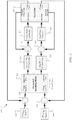
- FIGURE 3 illustrates an example temperature control system (TCS) 300 for a multi-stage cryocooler 310.
- the TCS 300 provides the multi-stage cryocooler 310 with load shifting capabilities and independently regulates the stages of the cryocooler 310 such that the temperatures of the stages can be independently controlled.
- the TCS 300 here includes a temperature controller 305, a compressor stroke setpoint controller (CSSPC) 315, a displacer phase setpoint controller (DPSPC) 320, a CSC 325, and a DPC 330.
- the temperature controller 305 includes processing circuitry configured to independently regulate the stages of the cryocooler 310, such as to independently control the heat lift at each stage in order to decrease the temperature settling time associated with heat load changes at a single stage.
- the temperature controller 305 decouples the effects of control variables (such as compressor stroke and displacer phase) on the individual stages.
- the temperature controller 305 can receive one or more temperature setpoints 335-340 corresponding to the respective stages of the cryocooler 310, such as from a user via an operator interface including a display, a touchscreen, an audio input, or other input/output device(s).
- the setpoints 335-340 can be stored in an internal memory of the temperature controller 305.
- the temperature controller 305 is coupled to the cryocooler 310 via a number of sensors, the CSSPC 315, the CSC 325, the DPSPC 320, and the DPC 330.
- the temperature controller 305 can receive temperature information regarding a cryocooler stage via a respective sensor.
- Various sensors can be configured to measure temperatures of respective stages of the cryocooler 310.
- the cryocooler 310 includes two stages, although embodiments with more stages could be used. Again, the temperature information could represent measurements of actual temperatures, temperature differentials, or other temperature measurements.
- the temperature controller 305 includes or is coupled to a number of comparators configured to compare a measured temperature with a temperature setpoint.
- a first comparator 345 receives and compares the measured temperature of the first stage of the cryocooler 310 with the temperature setpoint 335
- a second comparator 350 receives and compares the measured temperature of the second stage of the cryocooler 310 with the temperature setpoint 340.
- the comparators 345-350 compute temperature differentials or temperature errors for the stages of the cryocooler 310 based on the result of the comparisons. The temperature errors calculated by the comparators 345-350 are provided to the temperature controller 305.
- the temperature controller 305 In response to receiving the temperature information, the temperature controller 305 generates a Decoupler/Sensitivity matrix.
- the Decoupler/Sensitivity matrix is calculated as the inverse of the measured linearized response data measured from the cryocooler 310.
- the temperature controller 305 applies the temperature information to the Decoupler/Sensitivity matrix to calculate a compressor stroke error and a displacement phase error.
- the temperature controller 305 can apply a temperature differential or temperature error to the Decoupler/Sensitivity matrix to compute an amount to change a compressor stroke (compressor stroke error) and an amount to change a displacement phase (displacement phase error) for each stage.
- the Decoupler/Sensitivity matrix can be a function of operating condition.
- the decoupler matrix can equal A when controlling at 55K and 10K but will equal B when controlling at 85K and 30K and that can be stored or measured as a set of load maps.
- the temperature controller 305 controls one or more stages of the cryocooler 310 via one or more of the CSC 325 and the DPC 330.
- the temperature controller 305 provides the compressor stroke error to the CSSPC 315, which calculates a new compressor stroke setpoint.
- the temperature controller 305 also provides the displacement phase error to the DPSPC 320, which calculates a new displacement phase setpoint.
- the DPSPC 320 can be configured to receive a pressure-volume (displacement) phase measured at the cryocooler 310 and the pressure-volume (displacement) phase error, the DPSPC 320 configured to cause the DPC 330 to adjust a phase relationship between a pressure waveform and a volume waveform in the pressure-volume (displacement) phase of the cryocooler 310.
- a third comparator 355 receives and compares the new compressor stroke setpoint from the CSSPC 315 and a compressor stroke measured at the compressor of the cryocooler 310.
- a fourth comparator 360 receives and compares the new displacement phase setpoint from the DSSPC 320 and a displacement phase measured at the displacement cylinder of the cryocooler 310.
- the third comparator 355 is part of the CSC 325, and the fourth comparator 360 is part of the DPC 330.
- the CSC 325 determines an amount to adjust the compressor stroke of the cryocooler 310 based on the comparison of the new compressor stroke setpoint and the measured compressor stroke. The CSC 325 then adjusts the compressor stroke of the compressor of the cryocooler 310 by the determined amount.
- the DPC 330 determines an amount to adjust the displacement phase of the cryocooler 310 based on the comparison of the new displacement phase setpoint and the measured displacement phase. The DPC 330 then adjusts the displacement phase of the displacement cylinder in the cryocooler 310 by the determined amount by adjusting the phase relationship between the pressure waveform and the volume waveform in the cryocooler 310. Accordingly, in response to receiving the temperature information regarding the cryocooler 310, the temperature controller 305 is configured to independently control a temperature of each stage of the cryocooler 310.
- FIGURE 4 illustrates an example process 400 for controlling a temperature in a multi-stage cryocooler.
- the scenario shown in FIGURE 4 corresponds to a multi-stage cryocooler with two stages, although more stages could be used.
- the process 400 shown in FIGURE 4 may be utilized with components described in one or more of FIGURES 1 through 3 or with other components.
- a temperature controller receives temperature setpoints corresponding to respective stages of a multi-stage cryocooler.
- one or more setpoints such as temperature setpoints, are stored in an internal memory of the temperature controller.
- one or more sensors measure temperatures of respective stages of the cryocooler.
- the sensors provide the measured temperatures as part of temperature information to the temperature controller.
- the measured temperatures are provided to one or more comparators configured to compare the measured temperatures to the corresponding setpoints.
- a temperature error is calculated per stage at step 415.
- the temperature controller generates a Decoupler/Sensitivity matrix.
- the Decoupler/Sensitivity matrix is the inverse of the measured linearized data response of the multi-stage cryocooler.
- the Decoupler/Sensitivity matrix is pre-stored in a memory of the temperature controller.
- the temperature controller applies the temperature errors to the Decoupler/Sensitivity matrix to calculate a compressor stroke error and a displacement phase error at step 425.
- the CSC and DPC adjust the compressor setting and displacement cylinder phase.
- One or more sensors can measure the compressor setting, the displacement cylinder phase, or both.
- the sensors can provide the measured compressor setting, the displacement cylinder phase, or both to the CSC and DPC.
- the measured compressor setting and displacement cylinder phase are provided to one or more comparators configured to compare the measured compressor setting and displacement cylinder phase to corresponding setpoints to calculate an amount to adjust the compressor setting and an amount to adjust the displacement cylinder phase.
- the CSC and DPC use the calculated amounts to adjust the compressor setting and the displacement cylinder phase.
- the DPC can be configured to receive a pressure-volume (displacement) phase measured at the cryocooler and the pressure-volume (displacement) phase error, adjust a phase relationship between a pressure waveform and a volume waveform in the pressure-volume (displacement) phase of the cryocooler.
- FIGURE 5 illustrates an example load map 500 for controlling a temperature in a multi-stage cryocooler according to this disclosure.
- the load map 500 shown in FIGURE 5 corresponds to a multi-stage cryocooler with two stages, although more stages or different temperature ranges could be used.
- This load map 500 may be utilized with components described in one or more of FIGURES 1 through 3 or with other components.
- the example load map 500 corresponds to measurements taken of a multi-stage cryocooler as a performance metric, namely response data.
- all inputs to the cryocooler are maintained constant except for one: either the Stirling phase angle or the compressor input power is varied.
- a first series of lines 505 indicates the response of heat lifts at each stage due to changes in phase angle at constant compressor powers.
- a second series of lines 510 depicts the response of heat lifts at each stage due to changes in compressor power with constant phase angle.
- the response of one control input to all outputs is fairly linear, so the load map 500 illustrates how a change in one input affects all outputs in the system.
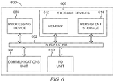
- FIGURE 6 illustrates an example computer 600 that may be used for controlling a temperature in a multi-stage cryocooler.
- the device 600 includes a bus system 602, which supports communication between at least one processing device 604, at least one storage device 606, at least one communications unit 608, and at least one input/output (I/O) unit 610.
- I/O input/output
- the processing device 604 executes instructions that may be loaded into a memory 612.
- the processing device 604 may include any suitable number(s) and type(s) of processors or other devices in any suitable arrangement.
- Example types of processing devices 604 include microprocessors, microcontrollers, digital signal processors, field programmable gate arrays, application specific integrated circuits, and discrete circuitry.
- the memory 612 and a persistent storage 614 are examples of storage devices 606, which represent any structure(s) capable of storing and facilitating retrieval of information (such as data, program code, and/or other suitable information on a temporary or permanent basis).
- the memory 612 may represent a random access memory or any other suitable volatile or non-volatile storage device(s).
- the persistent storage 614 may contain one or more components or devices supporting longer-term storage of data, such as a ready only memory, hard drive, Flash memory, or optical disc.
- the communications unit 608 supports communications with other systems or devices.
- the communications unit 608 could include a network interface card that facilitates communications over at least one Ethernet network.
- the communications unit 608 could also include a wireless transceiver facilitating communications over at least one wireless network.
- the communications unit 608 may support communications through any suitable physical or wireless communication link(s).
- the I/O unit 610 allows for input and output of data.
- the I/O unit 610 may provide a connection for user input through a keyboard, mouse, keypad, touchscreen, or other suitable input device.
- the I/O unit 610 may also send output to a display, printer, or other suitable output device.
- FIGURES 1 through 6 illustrate example cryocoolers and temperature control systems
- various changes may be made to FIGURES 1 through 6 .
- well-known processes have not been described in detail and have been omitted for brevity.
- specific steps, structures and materials may have been described, this disclosure may not be limited to these specifics, and others may be substituted as it is well understood by those skilled in the art, and various steps may not necessarily be performed in the sequences shown.
- any suitable multi-stage cryocooler could be used with the temperature control systems described above.
- the functional divisions shown in the temperature control systems are for illustration only, and various components could be combined, further subdivided, omitted, rearranged, or added according to particular needs.
- various functions described above are implemented or supported by a computer program that is formed from computer readable program code and that is embodied in a computer readable medium.
- computer readable program code includes any type of computer code, including source code, object code, and executable code.
- computer readable medium includes any type of medium capable of being accessed by a computer, such as read only memory (ROM), random access memory (RAM), a hard disk drive, a compact disc (CD), a digital video disc (DVD), or any other type of memory.
- ROM read only memory
- RAM random access memory
- CD compact disc
- DVD digital video disc
- a “non-transitory” computer readable medium excludes wired, wireless, optical, or other communication links that transport transitory electrical or other signals.
- a non-transitory computer readable medium includes media where data can be permanently stored and media where data can be stored and later overwritten, such as a rewritable optical disc or an erasable memory device.
- application and “program” refer to one or more computer programs, software components, sets of instructions, procedures, functions, objects, classes, instances, related data, or a portion thereof adapted for implementation in a suitable computer code (including source code, object code, or executable code).
- program refers to one or more computer programs, software components, sets of instructions, procedures, functions, objects, classes, instances, related data, or a portion thereof adapted for implementation in a suitable computer code (including source code, object code, or executable code).
- communicate as well as derivatives thereof, encompasses both direct and indirect communication.
- the term “or” is inclusive, meaning and/or.
- phrases "associated with,” as well as derivatives thereof, may mean to include, be included within, interconnect with, contain, be contained within, connect to or with, couple to or with, be communicable with, cooperate with, interleave, juxtapose, be proximate to, be bound to or with, have, have a property of, have a relationship to or with, or the like.
- the phrase "at least one of,” when used with a list of items, means that different combinations of one or more of the listed items may be used, and only one item in the list may be needed. For example, "at least one of: A, B, and C" includes any of the following combinations: A, B, C, A and B, A and C, B and C, and A and B and C.
Landscapes
- Engineering & Computer Science (AREA)
- Physics & Mathematics (AREA)
- Mechanical Engineering (AREA)
- Thermal Sciences (AREA)
- General Engineering & Computer Science (AREA)
- General Physics & Mathematics (AREA)
- Automation & Control Theory (AREA)
- Compressors, Vaccum Pumps And Other Relevant Systems (AREA)
Description
- This disclosure is directed generally to cryocoolers. More particularly, this disclosure is directed to temperature control of a multi-stage cryocooler with load shifting capabilities.
- A cryocooler is a thermal management device configured to extract heat from an object and, in doing so, cool the object to cryogenic temperatures. Many cryocoolers are designed to provide cooling to temperatures ranging from about 1.7 K to about 300 K (about -456°F to about 80°F). Cryocoolers can be used in many applications, including infrared detectors, space applications, space infrared sensor systems, and so forth.
-
US 5 535 593 A discloses a temperature control apparatus for a Stirling-cycle cryocooler having a temperature sensor and a controller for adjusting a compressor piston stroke amplitude based on a temperature error produced by a comparison between the sensed temperature and a temperature set point. -
US 5 018 357 A discloses a temperature control apparatus for a Stirling-cycle cryocooler having a temperature sensor and a controller for controlling drive of a reciprocating armature of the cooler based on a temperature error produced by a comparison between the sensed temperature and a temperature set point. - This disclosure provides temperature control of a multi-stage cryocooler with load shifting capabilities.
- The present invention provides an apparatus as defined in
claim 1. It comprises: a temperature control system configured to regulate temperatures of multiple stages of a multi-stage cryocooler, the temperature control system comprising: an input interface configured to receive (i) temperature setpoints for at least two of the stages of the multi-stage cryocooler and (ii) temperature information corresponding to temperatures measured at the at least two of the stages of the multi-stage cryocooler; processing circuitry configured to determine temperature errors for the at least two of the stages using the temperature setpoints and the temperature information and to calculate for each of the at least two of the stages at least one of a compressor stroke error and a pressure-volume phase error, using the temperature errors; and at least one controller configured to adjust at least one of a compressor setting and a pressure-volume phase of the multi-stage cryocooler for each of the at least two of the stages, to regulate the temperatures of the at least two of the stages independently, using at least one of the compressor stroke error and the pressure-volume phase error. - In an embodiment a system includes a multi-stage cryocooler having multiple stages and a temperature control system according to
claim 1 configured to regulate temperatures of the multiple stages of the multi-stage cryocooler. - A method according to the present invention is defined in claim 9. It comprises: cooling an object using a multi-stage cryocooler having multiple stages; and regulating a temperature of each stage of the multi-stage cryocooler by: receiving (i) temperature setpoints for at least two of the stages of the multi-stage cryocooler and (ii) temperature information corresponding to temperatures measured at the at least two of the stages of the multi-stage cryocooler; determining temperature errors for the at least two of the stages using the temperature setpoints and the temperature information; calculating for each of the at least two of the stages at least one of a compressor stroke error and a pressure-volume phase error using the temperature errors; and adjusting at least one of a compressor setting and a pressure-volume phase of the multi-stage cryocooler for each of the at least two of the stages, to regulate the temperatures of the at least two of the stages independently, using at least one of the compressor stroke error and the pressure-volume phase error.
- Other technical features may be readily apparent to one skilled in the art from the following figures, descriptions, and claims.
- For a more complete understanding of this disclosure, reference is now made to the following description, taken in conjunction with the accompanying drawings, in which:
-
FIGURE 1 illustrates an example cryocooler according to this invention; -
FIGURE 2 illustrates an example system including a temperature control system and a cryocooler according to this invention; -
FIGURE 3 illustrates an example temperature control system for a multi-stage cryocooler according to this invention; -
FIGURE 4 illustrates an example process for controlling a temperature in a multi-stage cryocooler according to this invention; -
FIGURE 5 illustrates an example load map for controlling a temperature in a multi-stage cryocooler according to this invention; and -
FIGURE 6 illustrates an example computer that may be used for controlling a temperature in a multi-stage cryocooler according to this invention. -
FIGURES 1 through 6 , described below, and the various embodiments used to describe the principles of the present invention in this patent document are by way of illustration only and should not be construed in any way to limit the scope of the invention as defined by the appended claims. Those skilled in the art will understand that the principles of the present invention may be implemented in any type of suitably arranged device or system. - Various types of cryocoolers have been designed and used in a number of different applications. For example, in a hybrid Stirling-Pulse Tube multi-stage cryocooler, the control inputs available (compressor stroke and pressure-volume phase) do not adjust a heat lift on the individual stages independently. The pressure volume (PV) phase is the phase of the thermodynamic process in the expander. One of the control inputs is compressor power and the other is an adjustment of the phase relationship between the Pressure and Volume waveforms in the expander. For example, the pressure-volume phase can be a displacer phase. The displacer phase is driven by the compressor, which sends a pressure wave to the displacer phase. In a first stage, the expander pre-cools the gas that enters the second stage, and the second stage pre-cools the gas enters the third stage, and so forth. A cooling capacity for each stage is proportional to the swept volume of the expansion space. Most applications of a multi-stage cryocooler would be better served if the temperature of both stages could be controlled independently, which can involve decoupling the effects of the control variables (such as the compressor stroke and the pressure-volume phase) on the individual stages. One benefit of independent control of the heat lift at each stage is to decrease the temperature settling time associated with heat load changes at a single stage.
- This disclosure provides a control system configured to regulate a temperature for each stage of a multi-stage cryocooler. Certain embodiments provide a multi-stage cryocooler with load shifting capabilities, which offers the potential for adjustment of the heat lift at each stage of the cryocooler. Certain embodiments are also configured to independently regulate the stages of a multi-stage cryocooler such that the temperatures of the stages can be independently controlled. Certain embodiments further support decoupling the effects of control variables (such as compressor stroke and pressure-volume phase) on the individual stages. In addition, certain embodiments provide a system and method for independent control of the heat lift at each stage to decrease the temperature settling time associated with heat load changes at a single stage. Further, certain embodiments independently control the temperatures/heat lifts at each cryocooler stage of a multi-stage cryocooler with load shifting capabilities by simultaneously adjusting multiple cryocooler operational parameter inputs (compressor power, pressure-volume phase, and the like). Certain embodiments control the PV phase by adjusting the displacement cylinder phase; however, other embodiments could use different methods to control that PV phase. Embodiments of the present disclosure describe a displacement phase to illustrate the PV phase. Although the term displacement phase is utilized herein below, embodiments utilizing a pressure-volume phase apply equally without departing from the scope of the present disclosure.
-
FIGURE 1 illustrates anexample cryocooler 100. Although certain details will be provided with reference to the components of thecryocooler 100 ofFIGURE 1 , it should be understood that other embodiments may include more, less, or different components. - The
cryocooler 100 ofFIGURE 1 is a thermal management device configured to extract heat from an object by compressing and expanding a working gas (such as helium, hydrogen, air, or the like) in a thermodynamic cycle. Thecryocooler 100 operates in this manner to extract heat from an object and, in doing so, cool the object to cryogenic temperatures, such as to below 150 K. In some embodiments, thecryocooler 100 is designed to provide cooling to temperatures ranging from about 1.7 K to about 300 K (about -456°F to about 80°F). In particular embodiments, thecryocooler 100 is a Stirling cycle cryocooler configured to progress through successive steps of isothermal compression, isochoric cooling, isothermal expansion, and isochoric heating. Thecryocooler 100 can be configured for use in many applications, including infrared detectors, space applications, space infrared sensor systems, and so forth. - As shown in
FIGURE 1 , thecryocooler 100 includes acompressor 105 and a displacer 110 sealed inside a housing. Thecompressor 105 includes twocompressor piston 115 each individually coupled to arespective compressor motor 120. Thecompressor motors 120 are configured to apply a force to therespective compressor pistons 115 in order to cause thecompressor pistons 115 to move back and forth. Thecompressor motors 120 represent any suitable type of motor, such as an electrical motor, a mechanical motor, an electromechanical motor, or a computer-driven motor. - The
displacer 110 includes adisplacer cylinder 125 coupled to adisplacer motor 130. Thedisplacer motor 130 moves thedisplacer cylinder 125 back and forth at the same frequency as thecompressor piston 115. Thedisplacer motor 130 represents any suitable type of motor, such as an electrical motor, a mechanical motor, an electromechanical motor, or a computer-driven motor. Aregenerator 135 is coupled to thedisplacer cylinder 125 and moves with thedisplacer cylinder 125. Aseal 140 is coupled between thedisplacer cylinder 125 and thecompressor pistons 115. -
FIGURE 2 illustrates anexample system 200 including a temperature control system (TCS) 205 and acryocooler 210 according to this disclosure. Thecryocooler 210 can represent a multi-stage cryocooler with load shifting capabilities, and theTCS 205 can independently regulate the stages of themulti-stage cryocooler 210 such that the temperature of the stages are independently controlled. Although certain details will be provided with reference to the components of thesystem 200 ofFIGURE 2 , it should be understood that other embodiments may include more, less, or different components. - As shown in
FIGURE 2 , thesystem 200 includes theTCS 205, thecryocooler 210, a compressor stroke controller (CSC) 215, and a displacer phase controller (DPC) 220. Thecryocooler 210 could represent thecryocooler 100 ofFIGURE 1 or any other suitable cryocooler. - The
TCS 205 is coupled to thecryocooler 210 via a number of sensors 230a-230b, theCSC 215, and theDPC 220. TheTCS 205 receives temperature information regarding different stages via respective sensors 230a-230b. TheTCS 205 controls one or more stages of thecryocooler 210 via one or more of theCSC 215 and theDPC 220. In response to receiving the temperature information from the sensors 230a-230b, theTCS 205 is configured to independently control a temperature of each stage of thecryocooler 210. For example, theTCS 205 can independently control a heat lift at each stage, decreasing the temperature settling time associated with heat load changes at a single stage. - The sensors 230a-230b are configured to measure temperatures of respective stages of the
cryocooler 210. For example, a first temperature sensor 230a can be configured to measure a temperature of a first stage of thecryocooler 210, and asecond temperature sensor 230b can be configured to measure a temperature of a second stage of thecryocooler 210. In the example shown inFIGURE 2 , thecryocooler 210 includes two stages, although other embodiments with more stages could be used. The temperature information from the sensors 230a-230b could represent measurements of actual temperatures, temperature differentials, or other temperature measurements. A temperature differential can represent a temperature error, such as a difference between a preferred or ideal temperature and a measured temperature or a difference between a measure temperature and a higher or lower temperature value in a range of preferred or ideal temperatures. In some embodiments, the temperature information includes an indication of whether the temperature is higher or lower than a preferred temperature or preferred temperature range. - The
TCS 205 is configured to independently control a temperature of each stage of thecryocooler 210 via a respective one of theCSC 215 and theDPC 220. TheCSC 215 is configured to control a compressor stroke setting of thecompressor 105 in thecryocooler 210, while theDPC 220 is configured to control a displacement phase of thedisplacement cylinder 125 in theThe displacer 110 of thecryocooler 210. - In response to receiving the temperature information from the sensors 230a-230b, the
TCS 205 can determine a temperature error with regard to one or more stages of thecryocooler 210. Using this information, theTCS 205 can then compute a compressor stroke error or displacement phase error. That is, theTCS 205 can compute an amount to adjust a temperature of the compressor, the displacement cylinder, or both. TheTCS 205 can command theCSC 215 to adjust the compressor stroke of thecompressor 105, or theTCS 205 can command theDPC 220 to adjust a displacement phase of thedisplacement cylinder 125. Additionally, theTCS 205 can command that adjustments be made by both theCSC 215 and theDPC 220. -
FIGURE 3 illustrates an example temperature control system (TCS) 300 for amulti-stage cryocooler 310. TheTCS 300 provides themulti-stage cryocooler 310 with load shifting capabilities and independently regulates the stages of thecryocooler 310 such that the temperatures of the stages can be independently controlled. Although certain details will be provided with reference to the components of theTCS 300 andcryocooler 310 ofFIGURE 3 , it should be understood that other embodiments may include more, less, or different components. - The
TCS 300 here includes atemperature controller 305, a compressor stroke setpoint controller (CSSPC) 315, a displacer phase setpoint controller (DPSPC) 320, aCSC 325, and aDPC 330. Thetemperature controller 305 includes processing circuitry configured to independently regulate the stages of thecryocooler 310, such as to independently control the heat lift at each stage in order to decrease the temperature settling time associated with heat load changes at a single stage. Thetemperature controller 305 decouples the effects of control variables (such as compressor stroke and displacer phase) on the individual stages. For example, thetemperature controller 305 can receive one or more temperature setpoints 335-340 corresponding to the respective stages of thecryocooler 310, such as from a user via an operator interface including a display, a touchscreen, an audio input, or other input/output device(s). The setpoints 335-340 can be stored in an internal memory of thetemperature controller 305. - The
temperature controller 305 is coupled to thecryocooler 310 via a number of sensors, theCSSPC 315, theCSC 325, theDPSPC 320, and theDPC 330. Thetemperature controller 305 can receive temperature information regarding a cryocooler stage via a respective sensor. Various sensors can be configured to measure temperatures of respective stages of thecryocooler 310. In the example shown inFIGURE 3 , thecryocooler 310 includes two stages, although embodiments with more stages could be used. Again, the temperature information could represent measurements of actual temperatures, temperature differentials, or other temperature measurements. - In some embodiments, the
temperature controller 305 includes or is coupled to a number of comparators configured to compare a measured temperature with a temperature setpoint. For example, afirst comparator 345 receives and compares the measured temperature of the first stage of thecryocooler 310 with thetemperature setpoint 335, and asecond comparator 350 receives and compares the measured temperature of the second stage of thecryocooler 310 with thetemperature setpoint 340. The comparators 345-350 compute temperature differentials or temperature errors for the stages of thecryocooler 310 based on the result of the comparisons. The temperature errors calculated by the comparators 345-350 are provided to thetemperature controller 305. - In response to receiving the temperature information, the
temperature controller 305 generates a Decoupler/Sensitivity matrix. The Decoupler/Sensitivity matrix is calculated as the inverse of the measured linearized response data measured from thecryocooler 310. Thetemperature controller 305 applies the temperature information to the Decoupler/Sensitivity matrix to calculate a compressor stroke error and a displacement phase error. For example, thetemperature controller 305 can apply a temperature differential or temperature error to the Decoupler/Sensitivity matrix to compute an amount to change a compressor stroke (compressor stroke error) and an amount to change a displacement phase (displacement phase error) for each stage. In addition, the Decoupler/Sensitivity matrix can be a function of operating condition. For example, the decoupler matrix can equal A when controlling at 55K and 10K but will equal B when controlling at 85K and 30K and that can be stored or measured as a set of load maps. - The
temperature controller 305 controls one or more stages of thecryocooler 310 via one or more of theCSC 325 and theDPC 330. Thetemperature controller 305 provides the compressor stroke error to theCSSPC 315, which calculates a new compressor stroke setpoint. Thetemperature controller 305 also provides the displacement phase error to theDPSPC 320, which calculates a new displacement phase setpoint. For example, theDPSPC 320 can be configured to receive a pressure-volume (displacement) phase measured at thecryocooler 310 and the pressure-volume (displacement) phase error, theDPSPC 320 configured to cause theDPC 330 to adjust a phase relationship between a pressure waveform and a volume waveform in the pressure-volume (displacement) phase of thecryocooler 310. - A
third comparator 355 receives and compares the new compressor stroke setpoint from theCSSPC 315 and a compressor stroke measured at the compressor of thecryocooler 310. Afourth comparator 360 receives and compares the new displacement phase setpoint from theDSSPC 320 and a displacement phase measured at the displacement cylinder of thecryocooler 310. In some embodiments, thethird comparator 355 is part of theCSC 325, and thefourth comparator 360 is part of theDPC 330. - The
CSC 325 determines an amount to adjust the compressor stroke of thecryocooler 310 based on the comparison of the new compressor stroke setpoint and the measured compressor stroke. TheCSC 325 then adjusts the compressor stroke of the compressor of thecryocooler 310 by the determined amount. TheDPC 330 determines an amount to adjust the displacement phase of thecryocooler 310 based on the comparison of the new displacement phase setpoint and the measured displacement phase. TheDPC 330 then adjusts the displacement phase of the displacement cylinder in thecryocooler 310 by the determined amount by adjusting the phase relationship between the pressure waveform and the volume waveform in thecryocooler 310. Accordingly, in response to receiving the temperature information regarding thecryocooler 310, thetemperature controller 305 is configured to independently control a temperature of each stage of thecryocooler 310. -
FIGURE 4 illustrates anexample process 400 for controlling a temperature in a multi-stage cryocooler. The scenario shown inFIGURE 4 corresponds to a multi-stage cryocooler with two stages, although more stages could be used. Theprocess 400 shown inFIGURE 4 may be utilized with components described in one or more ofFIGURES 1 through 3 or with other components. - At
step 405, a temperature controller receives temperature setpoints corresponding to respective stages of a multi-stage cryocooler. In some embodiments, one or more setpoints, such as temperature setpoints, are stored in an internal memory of the temperature controller. - At
step 410, one or more sensors measure temperatures of respective stages of the cryocooler. The sensors provide the measured temperatures as part of temperature information to the temperature controller. In some embodiments, the measured temperatures are provided to one or more comparators configured to compare the measured temperatures to the corresponding setpoints. - A temperature error is calculated per stage at
step 415. Atstep 420, the temperature controller generates a Decoupler/Sensitivity matrix. The Decoupler/Sensitivity matrix is the inverse of the measured linearized data response of the multi-stage cryocooler. In some embodiments, the Decoupler/Sensitivity matrix is pre-stored in a memory of the temperature controller. - The temperature controller applies the temperature errors to the Decoupler/Sensitivity matrix to calculate a compressor stroke error and a displacement phase error at
step 425. Atstep 430, the CSC and DPC adjust the compressor setting and displacement cylinder phase. One or more sensors can measure the compressor setting, the displacement cylinder phase, or both. The sensors can provide the measured compressor setting, the displacement cylinder phase, or both to the CSC and DPC. In some embodiments, the measured compressor setting and displacement cylinder phase are provided to one or more comparators configured to compare the measured compressor setting and displacement cylinder phase to corresponding setpoints to calculate an amount to adjust the compressor setting and an amount to adjust the displacement cylinder phase. The CSC and DPC use the calculated amounts to adjust the compressor setting and the displacement cylinder phase. For example, the DPC can be configured to receive a pressure-volume (displacement) phase measured at the cryocooler and the pressure-volume (displacement) phase error, adjust a phase relationship between a pressure waveform and a volume waveform in the pressure-volume (displacement) phase of the cryocooler. -
FIGURE 5 illustrates anexample load map 500 for controlling a temperature in a multi-stage cryocooler according to this disclosure. Theload map 500 shown inFIGURE 5 corresponds to a multi-stage cryocooler with two stages, although more stages or different temperature ranges could be used. Thisload map 500 may be utilized with components described in one or more ofFIGURES 1 through 3 or with other components. - The
example load map 500 corresponds to measurements taken of a multi-stage cryocooler as a performance metric, namely response data. To obtain theload map 500, all inputs to the cryocooler are maintained constant except for one: either the Stirling phase angle or the compressor input power is varied. A first series oflines 505 indicates the response of heat lifts at each stage due to changes in phase angle at constant compressor powers. A second series oflines 510 depicts the response of heat lifts at each stage due to changes in compressor power with constant phase angle. The response of one control input to all outputs is fairly linear, so theload map 500 illustrates how a change in one input affects all outputs in the system. -
FIGURE 6 illustrates anexample computer 600 that may be used for controlling a temperature in a multi-stage cryocooler. As shown inFIGURE 6 , thedevice 600 includes abus system 602, which supports communication between at least oneprocessing device 604, at least onestorage device 606, at least onecommunications unit 608, and at least one input/output (I/O)unit 610. - The
processing device 604 executes instructions that may be loaded into amemory 612. Theprocessing device 604 may include any suitable number(s) and type(s) of processors or other devices in any suitable arrangement. Example types ofprocessing devices 604 include microprocessors, microcontrollers, digital signal processors, field programmable gate arrays, application specific integrated circuits, and discrete circuitry. - The
memory 612 and apersistent storage 614 are examples ofstorage devices 606, which represent any structure(s) capable of storing and facilitating retrieval of information (such as data, program code, and/or other suitable information on a temporary or permanent basis). Thememory 612 may represent a random access memory or any other suitable volatile or non-volatile storage device(s). Thepersistent storage 614 may contain one or more components or devices supporting longer-term storage of data, such as a ready only memory, hard drive, Flash memory, or optical disc. - The
communications unit 608 supports communications with other systems or devices. For example, thecommunications unit 608 could include a network interface card that facilitates communications over at least one Ethernet network. Thecommunications unit 608 could also include a wireless transceiver facilitating communications over at least one wireless network. Thecommunications unit 608 may support communications through any suitable physical or wireless communication link(s). - The I/
O unit 610 allows for input and output of data. For example, the I/O unit 610 may provide a connection for user input through a keyboard, mouse, keypad, touchscreen, or other suitable input device. The I/O unit 610 may also send output to a display, printer, or other suitable output device. - Although
FIGURES 1 through 6 illustrate example cryocoolers and temperature control systems, various changes may be made toFIGURES 1 through 6 . For example, it will be understood that well-known processes have not been described in detail and have been omitted for brevity. Although specific steps, structures and materials may have been described, this disclosure may not be limited to these specifics, and others may be substituted as it is well understood by those skilled in the art, and various steps may not necessarily be performed in the sequences shown. Moreover, any suitable multi-stage cryocooler could be used with the temperature control systems described above. In addition, the functional divisions shown in the temperature control systems are for illustration only, and various components could be combined, further subdivided, omitted, rearranged, or added according to particular needs. - In some embodiments, various functions described above are implemented or supported by a computer program that is formed from computer readable program code and that is embodied in a computer readable medium. The phrase "computer readable program code" includes any type of computer code, including source code, object code, and executable code. The phrase "computer readable medium" includes any type of medium capable of being accessed by a computer, such as read only memory (ROM), random access memory (RAM), a hard disk drive, a compact disc (CD), a digital video disc (DVD), or any other type of memory. A "non-transitory" computer readable medium excludes wired, wireless, optical, or other communication links that transport transitory electrical or other signals. A non-transitory computer readable medium includes media where data can be permanently stored and media where data can be stored and later overwritten, such as a rewritable optical disc or an erasable memory device.
- It may be advantageous to set forth definitions of certain words and phrases used throughout this patent document. The terms "application" and "program" refer to one or more computer programs, software components, sets of instructions, procedures, functions, objects, classes, instances, related data, or a portion thereof adapted for implementation in a suitable computer code (including source code, object code, or executable code). The term "communicate," as well as derivatives thereof, encompasses both direct and indirect communication. The terms "include" and "comprise," as well as derivatives thereof, mean inclusion without limitation. The term "or" is inclusive, meaning and/or. The phrase "associated with," as well as derivatives thereof, may mean to include, be included within, interconnect with, contain, be contained within, connect to or with, couple to or with, be communicable with, cooperate with, interleave, juxtapose, be proximate to, be bound to or with, have, have a property of, have a relationship to or with, or the like. The phrase "at least one of," when used with a list of items, means that different combinations of one or more of the listed items may be used, and only one item in the list may be needed. For example, "at least one of: A, B, and C" includes any of the following combinations: A, B, C, A and B, A and C, B and C, and A and B and C.
- While this disclosure has described certain embodiments and generally associated methods, alterations and permutations of these embodiments and methods will be apparent to those skilled in the art. Accordingly, the above description of example embodiments does not define or constrain this disclosure. Other changes, substitutions, and alterations are also possible without departing from the scope of this disclosure, as defined by the following claims.
Claims (14)
- An apparatus comprising:
a temperature control system (TCS, 205) configured to regulate temperatures of multiple stages of a multi-stage cryocooler (210, 310), the temperature control system comprising:an input interface configured to receive (i) temperature setpoints (335, 340) for at least two of the stages of the multi-stage cryocooler and (ii) temperature information corresponding to temperatures measured at the at least two of the stages of the multi-stage cryocooler;processing circuitry (305, 345, 350, 355, 360) configured to determine temperature errors for the at least two of the stages using the temperature setpoints and the temperature information, and to calculate for each of the at least two of the stages at least one of a compressor stroke error and a pressure-volume phase error, using the temperature errors; andat least one controller (325, 330) configured to adjust at least one of a compressor setting and a pressure-volume phase of the multi-stage cryocooler for each of the at least two of the stages, to regulate the temperatures of the at least two of the stages independently, using at least one of the compressor stroke error and the pressure-volume phase error. - The apparatus of Claim 1, further comprising:
multiple sensors (230a, 230b) configured to measure the temperatures of the stages and provide the temperature information. - The apparatus of Claim 1, wherein the temperature information comprises at least one of a temperature differential, a value representative of the temperature differential, an actual temperature, a value representative of the actual temperature, an indication of whether the temperature is higher or lower than a preferred temperature, and an indication of whether the temperature is higher or lower than a preferred temperature range.
- The apparatus of Claim 1, wherein the processing circuitry is configured to calculate the compressor stroke error and the pressure-volume phase error by applying the determined temperature error to a Decoupler/Sensitivity matrix.
- The apparatus of Claim 4, wherein the processing circuitry is configured to generate (420) the Decoupler/Sensitivity matrix as an inverse of measured linearized response data from the multi-stage cryocooler.
- The apparatus of Claim 1, further comprising:
a compressor stroke setpoint controller (CSSPC, 315) configured to receive a compressor setting measured at the multi-stage cryocooler and the compressor stroke error, the compressor stroke setpoint controller configured to cause the at least one controller to adjust the compressor setting of the multi-stage cryocooler. - The apparatus of Claim 1, further comprising:
a pressure-volume phase setpoint controller (DPSPC, 320) configured to receive a pressure-volume phase measured at the multi-stage cryocooler and the pressure-volume phase error, the pressure-volume phase setpoint controller configured to cause the at least one controller to adjust a phase relationship between a pressure waveform and a volume waveform in the pressure-volume phase of the multi-stage cryocooler. - A system comprising:a multi-stage cryocooler (210) comprising multiple stages; andthe apparatus of any of claims 1 to 7 configured to regulate temperatures of the multiple stages of the multi-stage cryocooler.
- A method comprising:cooling an object using a multi-stage cryocooler comprising multiple stages; andregulating a temperature of each stage of the multi-stage cryocooler by:receiving (405) (i) temperature setpoints (335, 340) for at least two of the stages of the multi-stage cryocooler and (410) (ii) temperature information corresponding to temperatures measured at the at least two of the stages of the multi-stage cryocooler;determining temperature errors (415) for the at least two of the stages using the temperature setpoints and the temperature information;calculating (425) for each of the at least two of the stages at least one of a compressor stroke error and a pressure-volume phase error using the temperature errors; andadjusting (430) at least one of a compressor setting and a pressure-volume phase of the multi-stage cryocooler for each of the at least two of the stages, to regulate the temperatures of the at least two of the stages independently, using at least one of the compressor stroke error and the pressure-volume phase error.
- The method of Claim 9, further comprising:
measuring the temperatures of the stages of the multi-stage cryocooler using multiple sensors. - The method of Claim 9, wherein the temperature information comprises at least one of a temperature differential, a value representative of the temperature differential, an actual temperature, a value representative of the actual temperature, an indication of whether the temperature is higher or lower than a preferred temperature, and an indication of whether the temperature is higher or lower than a preferred temperature range.
- The method of Claim 9, wherein calculating at least one of the compressor stroke error and the pressure-volume phase error comprises:
applying the temperature errors to a Decoupler/Sensitivity matrix. - The method of Claim 12, further comprising:
generating (420) the Decoupler/Sensitivity matrix as an inverse of measured linearized response data from the multi-stage cryocooler. - The method of Claim 9, further comprising:receiving a compressor setting measured at the multi-stage cryocooler and the compressor stroke error;adjusting the compressor setting of the multi-stage cryocooler;receiving a pressure-volume phase measured at the multi-stage cryocooler and the pressure-volume phase error; andadjusting a phase relationship between a pressure waveform and a volume waveform in the pressure-volume phase of the multi-stage cryocooler.
Applications Claiming Priority (2)
| Application Number | Priority Date | Filing Date | Title |
|---|---|---|---|
| US14/456,821 US10060655B2 (en) | 2014-08-11 | 2014-08-11 | Temperature control of multi-stage cryocooler with load shifting capabilities |
| PCT/US2015/035362 WO2016025065A1 (en) | 2014-08-11 | 2015-06-11 | Temperature control of multi-stage cryocooler with load shifting capabilities |
Publications (2)
| Publication Number | Publication Date |
|---|---|
| EP3180572A1 EP3180572A1 (en) | 2017-06-21 |
| EP3180572B1 true EP3180572B1 (en) | 2020-04-22 |
Family
ID=53758508
Family Applications (1)
| Application Number | Title | Priority Date | Filing Date |
|---|---|---|---|
| EP15742417.7A Active EP3180572B1 (en) | 2014-08-11 | 2015-06-11 | Temperature control of multi-stage cryocooler with load shifting capabilities |
Country Status (6)
| Country | Link |
|---|---|
| US (1) | US10060655B2 (en) |
| EP (1) | EP3180572B1 (en) |
| JP (1) | JP6527581B2 (en) |
| CA (1) | CA2949375C (en) |
| IL (1) | IL249148B (en) |
| WO (1) | WO2016025065A1 (en) |
Families Citing this family (3)
| Publication number | Priority date | Publication date | Assignee | Title |
|---|---|---|---|---|
| US9551513B2 (en) * | 2014-06-12 | 2017-01-24 | Raytheon Company | Frequency-matched cryocooler scaling for low-cost, minimal disturbance space cooling |
| KR20160027350A (en) * | 2014-08-28 | 2016-03-10 | 에스케이하이닉스 주식회사 | Semiconductor device and semiconductor system using the same |
| WO2020049915A1 (en) * | 2018-09-03 | 2020-03-12 | 住友重機械工業株式会社 | Cryopump and method for monitoring cryopump |
Family Cites Families (18)
| Publication number | Priority date | Publication date | Assignee | Title |
|---|---|---|---|---|
| JPS59208360A (en) | 1983-05-13 | 1984-11-26 | アイシン精機株式会社 | Method of controlling refrigerator |
| US5018357A (en) | 1988-10-11 | 1991-05-28 | Helix Technology Corporation | Temperature control system for a cryogenic refrigeration |
| US5032772A (en) | 1989-12-04 | 1991-07-16 | Gully Wilfred J | Motor driver circuit for resonant linear cooler |
| US5535593A (en) * | 1994-08-22 | 1996-07-16 | Hughes Electronics | Apparatus and method for temperature control of a cryocooler by adjusting the compressor piston stroke amplitude |
| JPH0933124A (en) | 1995-05-12 | 1997-02-07 | Aisin Seiki Co Ltd | Multi-stage pulse tube refrigerator |
| US5715693A (en) * | 1996-07-19 | 1998-02-10 | Sunpower, Inc. | Refrigeration circuit having series evaporators and modulatable compressor |
| US6330800B1 (en) * | 1999-04-16 | 2001-12-18 | Raytheon Company | Apparatus and method for achieving temperature stability in a two-stage cryocooler |
| JP3936117B2 (en) | 2000-03-24 | 2007-06-27 | 株式会社東芝 | Pulse tube refrigerator and superconducting magnet system |
| JP2003279185A (en) | 2002-03-25 | 2003-10-02 | Aisin Seiki Co Ltd | Cryogenic refrigerator |
| US7266947B2 (en) | 2004-04-15 | 2007-09-11 | Sunpower, Inc. | Temperature control for free-piston cryocooler with gas bearings |
| US7779640B2 (en) * | 2005-09-09 | 2010-08-24 | Raytheon Company | Low vibration cryocooler |
| US20070261416A1 (en) | 2006-05-11 | 2007-11-15 | Raytheon Company | Hybrid cryocooler with multiple passive stages |
| JP4927642B2 (en) | 2007-05-28 | 2012-05-09 | キヤノンアネルバ株式会社 | Operation control method for two-stage refrigerator, operation control method for cryopump using two-stage refrigerator, two-stage refrigerator and cryopump |
| CN102099640B (en) | 2008-05-21 | 2013-03-27 | 布鲁克机械公司 | Linear drive cryogenic refrigerator |
| US8794016B2 (en) | 2008-08-14 | 2014-08-05 | Raytheon Company | Monitoring the health of a cryocooler |
| JP5891221B2 (en) | 2010-05-03 | 2016-03-22 | コンセホ・スペリオル・デ・インベスティガシオネス・シエンティフィカス(Csic) | Gas liquefaction system and method |
| US20130047632A1 (en) * | 2010-05-03 | 2013-02-28 | Consejo Superior De Investigaciones Cientificas (Csic) | Gas liquefaction system and method |
| TWI705187B (en) * | 2011-03-04 | 2020-09-21 | 美商艾德華真空有限責任公司 | A cryogenic refrigeration system and method for controlling supply of helium refrigerant |
-
2014
- 2014-08-11 US US14/456,821 patent/US10060655B2/en active Active
-
2015
- 2015-06-11 CA CA2949375A patent/CA2949375C/en active Active
- 2015-06-11 WO PCT/US2015/035362 patent/WO2016025065A1/en not_active Ceased
- 2015-06-11 EP EP15742417.7A patent/EP3180572B1/en active Active
- 2015-06-11 JP JP2017507409A patent/JP6527581B2/en active Active
-
2016
- 2016-11-23 IL IL249148A patent/IL249148B/en active IP Right Grant
Non-Patent Citations (1)
| Title |
|---|
| None * |
Also Published As
| Publication number | Publication date |
|---|---|
| CA2949375C (en) | 2021-09-28 |
| JP2017525923A (en) | 2017-09-07 |
| IL249148A0 (en) | 2017-01-31 |
| IL249148B (en) | 2020-11-30 |
| EP3180572A1 (en) | 2017-06-21 |
| US10060655B2 (en) | 2018-08-28 |
| US20160040913A1 (en) | 2016-02-11 |
| WO2016025065A1 (en) | 2016-02-18 |
| CA2949375A1 (en) | 2016-02-18 |
| JP6527581B2 (en) | 2019-06-05 |
Similar Documents
| Publication | Publication Date | Title |
|---|---|---|
| AU2008279515B2 (en) | Cooling control device and method | |
| CA2949375C (en) | Temperature control of multi-stage cryocooler with load shifting capabilities | |
| He | Dynamic modeling and multivariable control of vapor compression cycles in air conditioning systems | |
| CN103917833B (en) | For controlling the apparatus and method of low-temperature cooling system | |
| US20160132027A1 (en) | Dither switching extremum seeking control | |
| US6330800B1 (en) | Apparatus and method for achieving temperature stability in a two-stage cryocooler | |
| CA2949872C (en) | Adaptive phase control of cryocooler active vibration cancellation | |
| KR20160111012A (en) | Heat source system and control method therefor | |
| Rakova et al. | Process simulation of energy behaviour of pneumatic drives | |
| Shirazi et al. | Iterative optimal and adaptive control of a near isothermal liquid piston air compressor in a compressed air energy storage system | |
| Conrad et al. | Raytheon long life cryocoolers for future space missions | |
| Rakova et al. | Comparison of methods for the investigation on the energetic behaviour of pneumatic drives | |
| CN112648794A (en) | Rapid and accurate temperature control method for medical refrigerator and medical refrigerator | |
| US20130088176A1 (en) | Method For Use In Controlling Free Piston Stirling Coolers And Heat Pumps Driven By A Linear Alternator | |
| Rakova et al. | Exonomy analysis for the selection of the most cost-effective pneumatic drive solution | |
| Conrad et al. | FLIR FL-100 miniature linear Stirling cryocooler development summary | |
| Cheng et al. | Development of a 100-K pneumatically driven split-type cryogenic Stirling cryocooler based on experimental and numerical study | |
| Petric | Modeling of hydro-pneumatic energy storage system | |
| JP6219160B2 (en) | Turbo chiller maximum load factor calculation device and method, heat source system and number control method thereof | |
| US8965537B2 (en) | Method for ascertaining process values for a process control | |
| US20250035066A1 (en) | A system and a method for controlling the power output of a stirling engine | |
| RU2296983C1 (en) | Method for heat vision control of heat isolation of vessels and pipelines | |
| US11959694B2 (en) | Cryocooler health monitoring systems and methods | |
| CN118245709B (en) | Temperature control method, system, intelligent refrigerator and storage medium | |
| US20250060160A1 (en) | Real-time measurement of desublimation in a freeze-drying system |
Legal Events
| Date | Code | Title | Description |
|---|---|---|---|
| STAA | Information on the status of an ep patent application or granted ep patent |
Free format text: STATUS: THE INTERNATIONAL PUBLICATION HAS BEEN MADE |
|
| PUAI | Public reference made under article 153(3) epc to a published international application that has entered the european phase |
Free format text: ORIGINAL CODE: 0009012 |
|
| STAA | Information on the status of an ep patent application or granted ep patent |
Free format text: STATUS: REQUEST FOR EXAMINATION WAS MADE |
|
| 17P | Request for examination filed |
Effective date: 20170307 |
|
| AK | Designated contracting states |
Kind code of ref document: A1 Designated state(s): AL AT BE BG CH CY CZ DE DK EE ES FI FR GB GR HR HU IE IS IT LI LT LU LV MC MK MT NL NO PL PT RO RS SE SI SK SM TR |
|
| AX | Request for extension of the european patent |
Extension state: BA ME |
|
| DAV | Request for validation of the european patent (deleted) | ||
| DAX | Request for extension of the european patent (deleted) | ||
| GRAP | Despatch of communication of intention to grant a patent |
Free format text: ORIGINAL CODE: EPIDOSNIGR1 |
|
| STAA | Information on the status of an ep patent application or granted ep patent |
Free format text: STATUS: GRANT OF PATENT IS INTENDED |
|
| GRAJ | Information related to disapproval of communication of intention to grant by the applicant or resumption of examination proceedings by the epo deleted |
Free format text: ORIGINAL CODE: EPIDOSDIGR1 |
|
| STAA | Information on the status of an ep patent application or granted ep patent |
Free format text: STATUS: REQUEST FOR EXAMINATION WAS MADE |
|
| INTG | Intention to grant announced |
Effective date: 20191204 |
|
| INTC | Intention to grant announced (deleted) | ||
| GRAP | Despatch of communication of intention to grant a patent |
Free format text: ORIGINAL CODE: EPIDOSNIGR1 |
|
| STAA | Information on the status of an ep patent application or granted ep patent |
Free format text: STATUS: GRANT OF PATENT IS INTENDED |
|
| INTG | Intention to grant announced |
Effective date: 20200212 |
|
| GRAS | Grant fee paid |
Free format text: ORIGINAL CODE: EPIDOSNIGR3 |
|
| GRAA | (expected) grant |
Free format text: ORIGINAL CODE: 0009210 |
|
| STAA | Information on the status of an ep patent application or granted ep patent |
Free format text: STATUS: THE PATENT HAS BEEN GRANTED |
|
| AK | Designated contracting states |
Kind code of ref document: B1 Designated state(s): AL AT BE BG CH CY CZ DE DK EE ES FI FR GB GR HR HU IE IS IT LI LT LU LV MC MK MT NL NO PL PT RO RS SE SI SK SM TR |
|
| REG | Reference to a national code |
Ref country code: CH Ref legal event code: EP |
|
| REG | Reference to a national code |
Ref country code: IE Ref legal event code: FG4D |
|
| REG | Reference to a national code |
Ref country code: DE Ref legal event code: R096 Ref document number: 602015051154 Country of ref document: DE |
|
| REG | Reference to a national code |
Ref country code: AT Ref legal event code: REF Ref document number: 1260650 Country of ref document: AT Kind code of ref document: T Effective date: 20200515 |
|
| REG | Reference to a national code |
Ref country code: LT Ref legal event code: MG4D |
|
| REG | Reference to a national code |
Ref country code: NL Ref legal event code: MP Effective date: 20200422 |
|
| PG25 | Lapsed in a contracting state [announced via postgrant information from national office to epo] |
Ref country code: SE Free format text: LAPSE BECAUSE OF FAILURE TO SUBMIT A TRANSLATION OF THE DESCRIPTION OR TO PAY THE FEE WITHIN THE PRESCRIBED TIME-LIMIT Effective date: 20200422 Ref country code: LT Free format text: LAPSE BECAUSE OF FAILURE TO SUBMIT A TRANSLATION OF THE DESCRIPTION OR TO PAY THE FEE WITHIN THE PRESCRIBED TIME-LIMIT Effective date: 20200422 Ref country code: PT Free format text: LAPSE BECAUSE OF FAILURE TO SUBMIT A TRANSLATION OF THE DESCRIPTION OR TO PAY THE FEE WITHIN THE PRESCRIBED TIME-LIMIT Effective date: 20200824 Ref country code: NL Free format text: LAPSE BECAUSE OF FAILURE TO SUBMIT A TRANSLATION OF THE DESCRIPTION OR TO PAY THE FEE WITHIN THE PRESCRIBED TIME-LIMIT Effective date: 20200422 Ref country code: IS Free format text: LAPSE BECAUSE OF FAILURE TO SUBMIT A TRANSLATION OF THE DESCRIPTION OR TO PAY THE FEE WITHIN THE PRESCRIBED TIME-LIMIT Effective date: 20200822 Ref country code: GR Free format text: LAPSE BECAUSE OF FAILURE TO SUBMIT A TRANSLATION OF THE DESCRIPTION OR TO PAY THE FEE WITHIN THE PRESCRIBED TIME-LIMIT Effective date: 20200723 Ref country code: FI Free format text: LAPSE BECAUSE OF FAILURE TO SUBMIT A TRANSLATION OF THE DESCRIPTION OR TO PAY THE FEE WITHIN THE PRESCRIBED TIME-LIMIT Effective date: 20200422 Ref country code: NO Free format text: LAPSE BECAUSE OF FAILURE TO SUBMIT A TRANSLATION OF THE DESCRIPTION OR TO PAY THE FEE WITHIN THE PRESCRIBED TIME-LIMIT Effective date: 20200722 |
|
| REG | Reference to a national code |
Ref country code: AT Ref legal event code: MK05 Ref document number: 1260650 Country of ref document: AT Kind code of ref document: T Effective date: 20200422 |
|
| PG25 | Lapsed in a contracting state [announced via postgrant information from national office to epo] |
Ref country code: LV Free format text: LAPSE BECAUSE OF FAILURE TO SUBMIT A TRANSLATION OF THE DESCRIPTION OR TO PAY THE FEE WITHIN THE PRESCRIBED TIME-LIMIT Effective date: 20200422 Ref country code: HR Free format text: LAPSE BECAUSE OF FAILURE TO SUBMIT A TRANSLATION OF THE DESCRIPTION OR TO PAY THE FEE WITHIN THE PRESCRIBED TIME-LIMIT Effective date: 20200422 Ref country code: BG Free format text: LAPSE BECAUSE OF FAILURE TO SUBMIT A TRANSLATION OF THE DESCRIPTION OR TO PAY THE FEE WITHIN THE PRESCRIBED TIME-LIMIT Effective date: 20200722 Ref country code: RS Free format text: LAPSE BECAUSE OF FAILURE TO SUBMIT A TRANSLATION OF THE DESCRIPTION OR TO PAY THE FEE WITHIN THE PRESCRIBED TIME-LIMIT Effective date: 20200422 |
|
| PG25 | Lapsed in a contracting state [announced via postgrant information from national office to epo] |
Ref country code: AL Free format text: LAPSE BECAUSE OF FAILURE TO SUBMIT A TRANSLATION OF THE DESCRIPTION OR TO PAY THE FEE WITHIN THE PRESCRIBED TIME-LIMIT Effective date: 20200422 |
|
| REG | Reference to a national code |
Ref country code: DE Ref legal event code: R097 Ref document number: 602015051154 Country of ref document: DE |
|
| PG25 | Lapsed in a contracting state [announced via postgrant information from national office to epo] |
Ref country code: CZ Free format text: LAPSE BECAUSE OF FAILURE TO SUBMIT A TRANSLATION OF THE DESCRIPTION OR TO PAY THE FEE WITHIN THE PRESCRIBED TIME-LIMIT Effective date: 20200422 Ref country code: RO Free format text: LAPSE BECAUSE OF FAILURE TO SUBMIT A TRANSLATION OF THE DESCRIPTION OR TO PAY THE FEE WITHIN THE PRESCRIBED TIME-LIMIT Effective date: 20200422 Ref country code: IT Free format text: LAPSE BECAUSE OF FAILURE TO SUBMIT A TRANSLATION OF THE DESCRIPTION OR TO PAY THE FEE WITHIN THE PRESCRIBED TIME-LIMIT Effective date: 20200422 Ref country code: ES Free format text: LAPSE BECAUSE OF FAILURE TO SUBMIT A TRANSLATION OF THE DESCRIPTION OR TO PAY THE FEE WITHIN THE PRESCRIBED TIME-LIMIT Effective date: 20200422 Ref country code: DK Free format text: LAPSE BECAUSE OF FAILURE TO SUBMIT A TRANSLATION OF THE DESCRIPTION OR TO PAY THE FEE WITHIN THE PRESCRIBED TIME-LIMIT Effective date: 20200422 Ref country code: AT Free format text: LAPSE BECAUSE OF FAILURE TO SUBMIT A TRANSLATION OF THE DESCRIPTION OR TO PAY THE FEE WITHIN THE PRESCRIBED TIME-LIMIT Effective date: 20200422 Ref country code: EE Free format text: LAPSE BECAUSE OF FAILURE TO SUBMIT A TRANSLATION OF THE DESCRIPTION OR TO PAY THE FEE WITHIN THE PRESCRIBED TIME-LIMIT Effective date: 20200422 Ref country code: SM Free format text: LAPSE BECAUSE OF FAILURE TO SUBMIT A TRANSLATION OF THE DESCRIPTION OR TO PAY THE FEE WITHIN THE PRESCRIBED TIME-LIMIT Effective date: 20200422 Ref country code: MC Free format text: LAPSE BECAUSE OF FAILURE TO SUBMIT A TRANSLATION OF THE DESCRIPTION OR TO PAY THE FEE WITHIN THE PRESCRIBED TIME-LIMIT Effective date: 20200422 |
|
| REG | Reference to a national code |
Ref country code: CH Ref legal event code: PL |
|
| PG25 | Lapsed in a contracting state [announced via postgrant information from national office to epo] |
Ref country code: SK Free format text: LAPSE BECAUSE OF FAILURE TO SUBMIT A TRANSLATION OF THE DESCRIPTION OR TO PAY THE FEE WITHIN THE PRESCRIBED TIME-LIMIT Effective date: 20200422 Ref country code: PL Free format text: LAPSE BECAUSE OF FAILURE TO SUBMIT A TRANSLATION OF THE DESCRIPTION OR TO PAY THE FEE WITHIN THE PRESCRIBED TIME-LIMIT Effective date: 20200422 |
|
| PLBE | No opposition filed within time limit |
Free format text: ORIGINAL CODE: 0009261 |
|
| STAA | Information on the status of an ep patent application or granted ep patent |
Free format text: STATUS: NO OPPOSITION FILED WITHIN TIME LIMIT |
|
| 26N | No opposition filed |
Effective date: 20210125 |
|
| PG25 | Lapsed in a contracting state [announced via postgrant information from national office to epo] |
Ref country code: LU Free format text: LAPSE BECAUSE OF NON-PAYMENT OF DUE FEES Effective date: 20200611 |
|
| REG | Reference to a national code |
Ref country code: BE Ref legal event code: MM Effective date: 20200630 |
|
| PG25 | Lapsed in a contracting state [announced via postgrant information from national office to epo] |
Ref country code: LI Free format text: LAPSE BECAUSE OF NON-PAYMENT OF DUE FEES Effective date: 20200630 Ref country code: IE Free format text: LAPSE BECAUSE OF NON-PAYMENT OF DUE FEES Effective date: 20200611 Ref country code: CH Free format text: LAPSE BECAUSE OF NON-PAYMENT OF DUE FEES Effective date: 20200630 |
|
| PG25 | Lapsed in a contracting state [announced via postgrant information from national office to epo] |
Ref country code: BE Free format text: LAPSE BECAUSE OF NON-PAYMENT OF DUE FEES Effective date: 20200630 Ref country code: SI Free format text: LAPSE BECAUSE OF FAILURE TO SUBMIT A TRANSLATION OF THE DESCRIPTION OR TO PAY THE FEE WITHIN THE PRESCRIBED TIME-LIMIT Effective date: 20200422 |
|
| PG25 | Lapsed in a contracting state [announced via postgrant information from national office to epo] |
Ref country code: TR Free format text: LAPSE BECAUSE OF FAILURE TO SUBMIT A TRANSLATION OF THE DESCRIPTION OR TO PAY THE FEE WITHIN THE PRESCRIBED TIME-LIMIT Effective date: 20200422 Ref country code: MT Free format text: LAPSE BECAUSE OF FAILURE TO SUBMIT A TRANSLATION OF THE DESCRIPTION OR TO PAY THE FEE WITHIN THE PRESCRIBED TIME-LIMIT Effective date: 20200422 Ref country code: CY Free format text: LAPSE BECAUSE OF FAILURE TO SUBMIT A TRANSLATION OF THE DESCRIPTION OR TO PAY THE FEE WITHIN THE PRESCRIBED TIME-LIMIT Effective date: 20200422 |
|
| PG25 | Lapsed in a contracting state [announced via postgrant information from national office to epo] |
Ref country code: MK Free format text: LAPSE BECAUSE OF FAILURE TO SUBMIT A TRANSLATION OF THE DESCRIPTION OR TO PAY THE FEE WITHIN THE PRESCRIBED TIME-LIMIT Effective date: 20200422 |
|
| P01 | Opt-out of the competence of the unified patent court (upc) registered |
Effective date: 20230530 |
|
| PGFP | Annual fee paid to national office [announced via postgrant information from national office to epo] |
Ref country code: DE Payment date: 20250520 Year of fee payment: 11 |
|
| PGFP | Annual fee paid to national office [announced via postgrant information from national office to epo] |
Ref country code: GB Payment date: 20250520 Year of fee payment: 11 |
|
| PGFP | Annual fee paid to national office [announced via postgrant information from national office to epo] |
Ref country code: FR Payment date: 20250520 Year of fee payment: 11 |