EP3179723A1 - Method for deriving a temporal predictive motion vector, and apparatus using the method - Google Patents
Method for deriving a temporal predictive motion vector, and apparatus using the method Download PDFInfo
- Publication number
- EP3179723A1 EP3179723A1 EP17153707.9A EP17153707A EP3179723A1 EP 3179723 A1 EP3179723 A1 EP 3179723A1 EP 17153707 A EP17153707 A EP 17153707A EP 3179723 A1 EP3179723 A1 EP 3179723A1
- Authority
- EP
- European Patent Office
- Prior art keywords
- block
- prediction
- collocated
- collocated block
- lcu
- Prior art date
- Legal status (The legal status is an assumption and is not a legal conclusion. Google has not performed a legal analysis and makes no representation as to the accuracy of the status listed.)
- Granted
Links
- 239000013598 vector Substances 0.000 title claims abstract description 110
- 230000002123 temporal effect Effects 0.000 title claims abstract description 101
- 238000000034 method Methods 0.000 title claims abstract description 100
- 238000001914 filtration Methods 0.000 description 28
- 230000008707 rearrangement Effects 0.000 description 13
- 208000037170 Delayed Emergence from Anesthesia Diseases 0.000 description 7
- 238000013139 quantization Methods 0.000 description 7
- 241000023320 Luma <angiosperm> Species 0.000 description 5
- 238000009795 derivation Methods 0.000 description 5
- OSWPMRLSEDHDFF-UHFFFAOYSA-N methyl salicylate Chemical compound COC(=O)C1=CC=CC=C1O OSWPMRLSEDHDFF-UHFFFAOYSA-N 0.000 description 5
- 238000010586 diagram Methods 0.000 description 4
- 230000006870 function Effects 0.000 description 4
- 238000005192 partition Methods 0.000 description 4
- 230000008569 process Effects 0.000 description 4
- 230000005540 biological transmission Effects 0.000 description 3
- 230000006835 compression Effects 0.000 description 3
- 238000007906 compression Methods 0.000 description 3
- 238000012986 modification Methods 0.000 description 3
- 230000004048 modification Effects 0.000 description 3
- 230000003044 adaptive effect Effects 0.000 description 2
- 230000008859 change Effects 0.000 description 1
- 230000001419 dependent effect Effects 0.000 description 1
- 230000000694 effects Effects 0.000 description 1
- 238000005516 engineering process Methods 0.000 description 1
- 238000009499 grossing Methods 0.000 description 1
- 238000010845 search algorithm Methods 0.000 description 1
- 238000000926 separation method Methods 0.000 description 1
- 230000001131 transforming effect Effects 0.000 description 1
Images


Classifications
-
- H—ELECTRICITY
- H04—ELECTRIC COMMUNICATION TECHNIQUE
- H04N—PICTORIAL COMMUNICATION, e.g. TELEVISION
- H04N19/00—Methods or arrangements for coding, decoding, compressing or decompressing digital video signals
-
- H—ELECTRICITY
- H04—ELECTRIC COMMUNICATION TECHNIQUE
- H04N—PICTORIAL COMMUNICATION, e.g. TELEVISION
- H04N19/00—Methods or arrangements for coding, decoding, compressing or decompressing digital video signals
- H04N19/10—Methods or arrangements for coding, decoding, compressing or decompressing digital video signals using adaptive coding
- H04N19/102—Methods or arrangements for coding, decoding, compressing or decompressing digital video signals using adaptive coding characterised by the element, parameter or selection affected or controlled by the adaptive coding
- H04N19/103—Selection of coding mode or of prediction mode
- H04N19/109—Selection of coding mode or of prediction mode among a plurality of temporal predictive coding modes
-
- H—ELECTRICITY
- H04—ELECTRIC COMMUNICATION TECHNIQUE
- H04N—PICTORIAL COMMUNICATION, e.g. TELEVISION
- H04N19/00—Methods or arrangements for coding, decoding, compressing or decompressing digital video signals
- H04N19/10—Methods or arrangements for coding, decoding, compressing or decompressing digital video signals using adaptive coding
- H04N19/134—Methods or arrangements for coding, decoding, compressing or decompressing digital video signals using adaptive coding characterised by the element, parameter or criterion affecting or controlling the adaptive coding
- H04N19/157—Assigned coding mode, i.e. the coding mode being predefined or preselected to be further used for selection of another element or parameter
- H04N19/159—Prediction type, e.g. intra-frame, inter-frame or bidirectional frame prediction
-
- G—PHYSICS
- G06—COMPUTING; CALCULATING OR COUNTING
- G06T—IMAGE DATA PROCESSING OR GENERATION, IN GENERAL
- G06T9/00—Image coding
- G06T9/004—Predictors, e.g. intraframe, interframe coding
-
- H—ELECTRICITY
- H04—ELECTRIC COMMUNICATION TECHNIQUE
- H04N—PICTORIAL COMMUNICATION, e.g. TELEVISION
- H04N19/00—Methods or arrangements for coding, decoding, compressing or decompressing digital video signals
- H04N19/60—Methods or arrangements for coding, decoding, compressing or decompressing digital video signals using transform coding
- H04N19/61—Methods or arrangements for coding, decoding, compressing or decompressing digital video signals using transform coding in combination with predictive coding
-
- H—ELECTRICITY
- H04—ELECTRIC COMMUNICATION TECHNIQUE
- H04N—PICTORIAL COMMUNICATION, e.g. TELEVISION
- H04N19/00—Methods or arrangements for coding, decoding, compressing or decompressing digital video signals
- H04N19/10—Methods or arrangements for coding, decoding, compressing or decompressing digital video signals using adaptive coding
- H04N19/102—Methods or arrangements for coding, decoding, compressing or decompressing digital video signals using adaptive coding characterised by the element, parameter or selection affected or controlled by the adaptive coding
- H04N19/103—Selection of coding mode or of prediction mode
- H04N19/105—Selection of the reference unit for prediction within a chosen coding or prediction mode, e.g. adaptive choice of position and number of pixels used for prediction
-
- H—ELECTRICITY
- H04—ELECTRIC COMMUNICATION TECHNIQUE
- H04N—PICTORIAL COMMUNICATION, e.g. TELEVISION
- H04N19/00—Methods or arrangements for coding, decoding, compressing or decompressing digital video signals
- H04N19/10—Methods or arrangements for coding, decoding, compressing or decompressing digital video signals using adaptive coding
- H04N19/134—Methods or arrangements for coding, decoding, compressing or decompressing digital video signals using adaptive coding characterised by the element, parameter or criterion affecting or controlling the adaptive coding
- H04N19/136—Incoming video signal characteristics or properties
-
- H—ELECTRICITY
- H04—ELECTRIC COMMUNICATION TECHNIQUE
- H04N—PICTORIAL COMMUNICATION, e.g. TELEVISION
- H04N19/00—Methods or arrangements for coding, decoding, compressing or decompressing digital video signals
- H04N19/10—Methods or arrangements for coding, decoding, compressing or decompressing digital video signals using adaptive coding
- H04N19/134—Methods or arrangements for coding, decoding, compressing or decompressing digital video signals using adaptive coding characterised by the element, parameter or criterion affecting or controlling the adaptive coding
- H04N19/167—Position within a video image, e.g. region of interest [ROI]
-
- H—ELECTRICITY
- H04—ELECTRIC COMMUNICATION TECHNIQUE
- H04N—PICTORIAL COMMUNICATION, e.g. TELEVISION
- H04N19/00—Methods or arrangements for coding, decoding, compressing or decompressing digital video signals
- H04N19/10—Methods or arrangements for coding, decoding, compressing or decompressing digital video signals using adaptive coding
- H04N19/169—Methods or arrangements for coding, decoding, compressing or decompressing digital video signals using adaptive coding characterised by the coding unit, i.e. the structural portion or semantic portion of the video signal being the object or the subject of the adaptive coding
- H04N19/17—Methods or arrangements for coding, decoding, compressing or decompressing digital video signals using adaptive coding characterised by the coding unit, i.e. the structural portion or semantic portion of the video signal being the object or the subject of the adaptive coding the unit being an image region, e.g. an object
- H04N19/176—Methods or arrangements for coding, decoding, compressing or decompressing digital video signals using adaptive coding characterised by the coding unit, i.e. the structural portion or semantic portion of the video signal being the object or the subject of the adaptive coding the unit being an image region, e.g. an object the region being a block, e.g. a macroblock
-
- H—ELECTRICITY
- H04—ELECTRIC COMMUNICATION TECHNIQUE
- H04N—PICTORIAL COMMUNICATION, e.g. TELEVISION
- H04N19/00—Methods or arrangements for coding, decoding, compressing or decompressing digital video signals
- H04N19/30—Methods or arrangements for coding, decoding, compressing or decompressing digital video signals using hierarchical techniques, e.g. scalability
-
- H—ELECTRICITY
- H04—ELECTRIC COMMUNICATION TECHNIQUE
- H04N—PICTORIAL COMMUNICATION, e.g. TELEVISION
- H04N19/00—Methods or arrangements for coding, decoding, compressing or decompressing digital video signals
- H04N19/44—Decoders specially adapted therefor, e.g. video decoders which are asymmetric with respect to the encoder
-
- H—ELECTRICITY
- H04—ELECTRIC COMMUNICATION TECHNIQUE
- H04N—PICTORIAL COMMUNICATION, e.g. TELEVISION
- H04N19/00—Methods or arrangements for coding, decoding, compressing or decompressing digital video signals
- H04N19/50—Methods or arrangements for coding, decoding, compressing or decompressing digital video signals using predictive coding
- H04N19/503—Methods or arrangements for coding, decoding, compressing or decompressing digital video signals using predictive coding involving temporal prediction
- H04N19/51—Motion estimation or motion compensation
- H04N19/513—Processing of motion vectors
- H04N19/517—Processing of motion vectors by encoding
- H04N19/52—Processing of motion vectors by encoding by predictive encoding
-
- H—ELECTRICITY
- H04—ELECTRIC COMMUNICATION TECHNIQUE
- H04N—PICTORIAL COMMUNICATION, e.g. TELEVISION
- H04N19/00—Methods or arrangements for coding, decoding, compressing or decompressing digital video signals
- H04N19/50—Methods or arrangements for coding, decoding, compressing or decompressing digital video signals using predictive coding
- H04N19/503—Methods or arrangements for coding, decoding, compressing or decompressing digital video signals using predictive coding involving temporal prediction
- H04N19/51—Motion estimation or motion compensation
- H04N19/56—Motion estimation with initialisation of the vector search, e.g. estimating a good candidate to initiate a search
-
- G—PHYSICS
- G06—COMPUTING; CALCULATING OR COUNTING
- G06T—IMAGE DATA PROCESSING OR GENERATION, IN GENERAL
- G06T9/00—Image coding
- G06T9/40—Tree coding, e.g. quadtree, octree
Definitions
- the present invention relates to a video encoding and decoding method, and more specifically, the present invention pertains to a method for deriving a temporal prediction motion vector and an apparatus for using this method.
- HD High Definition
- UHD Ultra High Definition
- a number of scheme have been introduced for a video compression, such as inter prediction scheme that predicts pixel values included in a current picture from a picture before or after the current picture, intra prediction scheme that predicts pixel values included in a current picture using pixel information in the current picture, and entropy encoding scheme that assigns a shorter codeword to a value that happens more frequently while assigning a longer codeword to a value that happens less frequently.
- Such video compression schemes may be utilized to effectively compress, transmit, or store video data.
- An object of the present invention is to provide a method of deriving a temporal prediction motion vector for a block adjoining with an LCU boundary.
- Another object of the present invention is to provide an apparatus of performing a method of deriving a temporal prediction motion vector for a block adjoining with an LCU boundary.
- a video decoding method includes the steps of determining a reference picture index of a collocated block of a prediction target block; and determining a motion prediction vector of the collocated block, the collocated block is a block adaptively determined by a location of the prediction target block within a Largest Coding Unit (LCU).
- LCU Largest Coding Unit
- the collocated block may be differently determined by deciding whether a lower boundary of the prediction target block adjoins with an LCU boundary.
- the collocated block may be differently determined by deciding whether a lower boundary of the prediction target block adjoins with an LCU boundary and whether only a right boundary of the prediction target block adjoins with the LCU boundary.
- the collocated block may be determined by referencing positions of pixels within the LCU. If a left side or lower boundary of the prediction target block does not adjoin with the LCU boundary, a first collocated block and a fifth collocated block are sequentially determined as the collocated block according to an availability of the collocated block at a corresponding position.
- a video decoding method may include the steps of determining whether a boundary of a prediction target block adjoins with a boundary of a LCU; and determining an availability of a first collocated block according to the determination of whether the boundary of the prediction target block adjoins with the boundary of the LCU.
- the video decoding method may further include the step of determining other collocated block except for the first collocated block as a collocated block to derive a temporal prediction motion vector if it is determined that the first collocated block is not available.
- the step of determining the other collocated block except for the first collocated block as the collocated block to derive the temporal prediction motion vector if the first collocated block is not available is a step for determining different collocated blocks to derive the temporal prediction motion vector for a case where a lower boundary of the prediction target block adjoins with the boundary of the LCU and for a case where only a right boundary of the prediction target block adjoins with the boundary of the LCU.
- the step of determining the availability of the first collocated block according to the determination of whether the boundary of the prediction target block is adjoined with the boundary of the LCU is a step for determining the first collocated block as unavailable if a lower boundary of the prediction target block adjoins with the boundary of the LCU.
- the step of determining the first collocated block as the collocated block to derive the temporal prediction motion vector if the first collocated block is available, or determining an availability of a fifth collocated block if the first collocated block is not available, may be further comprised.
- a video decoding apparatus includes an entropy decoding unit that decodes LCU size information and a prediction unit that determines a reference picture index of a collocated block of a prediction target block and determines a motion prediction vector of the collocated block, wherein the collocated block is a block adaptively determined by a location of the prediction target block within an LCU.
- the collocated block may be differently determined by deciding whether a lower boundary of the prediction target block adjoins with an LCU boundary.
- the collocated block may be differently determined by deciding whether a lower boundary of the prediction target block adjoins with an LCU boundary and whether only a right boundary of the prediction target block adjoins with the LCU boundary.
- the collocated block may be determined by referencing positions of pixels within the LCU. If a left side or lower boundary of the prediction target block is not adjoined with the LCU boundary, a first collocated block and a fifth collocated block are sequentially determined as the collocated block according to an availability of the collocated block at a corresponding position.
- a video decoding unit may include an entropy decoding unit that decodes LCU size information and a prediction unit that determines whether a boundary of a prediction target block adjoins with a boundary of an LCU and determines an availability of a first collocated block according to the determination of whether the boundary of the prediction target block adjoins with the boundary of the LCU.
- the prediction unit may determine other collocated block except for the first collocated block as a collocated block to derive a temporal prediction motion vector if it is determined that the first collocated block is not available.
- the prediction unit may determine different collocated blocks to derive the temporal prediction motion vector for a case where a lower boundary of the prediction target block adjoins with the boundary of the LCU and for a case where only a right boundary of the prediction target block adjoins with the boundary of the LCU.
- the prediction unit may determine the first collocated block as unavailable if a lower boundary of the prediction target block adjoins with the boundary of the LCU.
- the prediction unit may determine the first collocated block as the collocated block to derive the temporal prediction motion vector if the first collocated block is available, or may determine an availability of a fifth collocated block if the first collocated block is not available.
- the method of deriving a temporal prediction motion vector and an apparatus of using the method according to an embodiment of the present invention may differently use a collocated (or co-located or colocated) picture, from which a temporal motion vector derived, depending on whether a prediction target block adjoins an LCU.
- a collocated (or co-located or colocated) picture from which a temporal motion vector derived, depending on whether a prediction target block adjoins an LCU.
- first and second may be used to describe various components (or feature). However the components are not limited thereto. These terms are used only to distinguish one component from another. For example, the first component may be also named as the second component, and the second component may be similarly named as the first component.
- the term “and/or” includes a combination of a plurality of related items as described herein or any one of the plurality of related items.
- ком ⁇ онент When a component (or feature) is “connected” or “coupled” to another component, the component may be directly connected or coupled to the other component. In contrast, when a component is “directly connected or coupled” to another component, no component intervenes.
- Fig. 1 is a block diagram illustrating a video encoding apparatus according to an embodiment of the present invention.
- the video encoding apparatus 100 may include a picture splitting module 110, an inter prediction module 120, an intra prediction module 125, a transform module 130, a quantization module 135, a re-arrangement module 160, an entropy encoding module 165, a dequantization module 140, an inverse transform module 145, a filtering module 150, and a memory 155.
- Each module of Fig. 1 are shown independently from each other to represent different functions from each other in the video encoding apparatus, but this does not mean that each module should be implemented in a separated hardware or software module (component) unit. That is, for convenience of description, the modules are shown to be provided independently, and at least two of the modules may be combined to constitute one module, or one of the modules may be divided into a plurality of modules to perform functions. Embodiments of combinations of the modules or embodiments of separation of the modules are also included in the scope of the present invention without departing from the gist of the present invention.
- modules may be not essential modules that perform essential functions of the present invention but may be rather optional modules to enhance performance.
- the present invention may include only the essential modules necessary to implement the gist of the present invention excluding the modules merely used for better performance, and this structure is also included in the scope of the present invention.
- a picture splitting module 110 may split an input picture into at least one processing unit.
- the processing unit may be a prediction unit (PU), a transform unit (TU), or a coding unit (CU).
- the picture splitting module 110 may encode the picture by splitting one picture into a combination of a plurality of coding units, prediction units, and transform units, and a combination of one coding unit, prediction unit and transform unit may be selected according to a predetermined standard (or reference) such as a cost function and may be encoded.
- one picture may be split into a plurality of coding units.
- a recursive tree structure such as quad tree structure, may be used to split a picture into coding units.
- a coding unit With a picture or a largest coding unit as a root, a coding unit may be split into other coding units as many child nodes as the number of the split coding units.
- the coding unit that is no more split due to a predetermined limitation is to be a leaf node. That is, assuming that only square-shape split is available for a coding unit, the coding unit may be split into a maximum of four other coding units.
- the coding unit may mean a unit in which decoding as well as encoding is performed.
- a prediction unit may be partitioned with a form of at least one square or rectangle having a same size within a coding unit.
- intra prediction may be performed without splitting the prediction unit into a plurality of NxN prediction units.
- a prediction module may include an inter prediction module 120 that performs an inter prediction and an intra prediction module 125 that performs an intra prediction. It may be determined whether to perform the inter prediction or intra prediction with respect to the prediction unit, and according to each prediction method, specific information (e.g., intra prediction mode, motion vector, reference picture, etc.) may be determined.
- a processing unit on which prediction is performed may differ from a processing unit on which the prediction method and its details are determined.
- the prediction method and prediction mode may be determined by a prediction unit, and a performance of the prediction may be performed in a transform unit.
- a residual value (residual block) between a generated prediction block and an original block may be input to the transform module 130. Further, the prediction mode information and motion vector information, etc.
- the original block may be encoded and transmitted to the decoding apparatus.
- the inter prediction module may predict a prediction unit based on information of at least one picture among pictures prior to a current picture or pictures after the current picture.
- the inter prediction module may include a reference picture interpolation module, a motion prediction module, and a motion compensation module.
- the reference picture interpolation module may receive reference picture information from the memory 155 and may generate pixel information in the unit of less than an integer pixel unit within the reference picture.
- a DCT-based 8 tap interpolation filter with different filter coefficients for each tap may be used to generate the pixel information in the unit of less than the integer pixel unit, a unit of 1/4 pixel.
- a DCT-based 4 tap interpolation filter with different filter coefficients for each tap may be used to generate the pixel information in the unit of less than the integer pixel unit, a unit of 1/8 pixel.
- a motion prediction module may perform motion prediction based on a reference picture interpolated by the reference picture interpolation module.
- various methods may be used, such as FBMA (Full search-based Block Matching Algorithm), TSS (Three Step Search), NTS (New Three-Step Search Algorithm), etc.
- the motion vector may have a motion vector value in a 1/2 pixel unit or in a 1/4 pixel unit based on an interpolated pixel.
- the motion prediction module may predict a current prediction unit by applying various motion prediction method.
- various methods may be used, such as a skip method, a merge method, or an AMVP (Advanced Motion Vector Prediction) method.
- the inter prediction module may determine whether a boundary of a prediction target block adjoins with a boundary of an LCU (Largest Coding Unit), and may determine whether a first collocated (or colocated or co-located) block is available according to the determination of whether the boundary of the prediction target block adjoins with the boundary of the LCU. For example, in case the first collocated block is not available, a second collocated block may be determined as a collocated block to derive a temporal prediction motion vector. Or in case the first collocated block is not available, a position of the first collocated block may be changed, and the position-changed first collocated block may be determined as a collocated block to derive a temporal prediction motion vector.
- LCU Large Coding Unit
- the inter prediction module may include a predicting module that determines a reference picture index of a collocated block of a prediction target block and determines a motion prediction vector of the collocated block.
- the collocated block may be adaptively determined according to a location of the prediction target block in the LCU (Largest Coding Unit).
- LCU Large Coding Unit
- the inter prediction module may generate a prediction unit based on information on a reference pixel neighboring to the current block, which is pixel information on pixels in the current picture.
- the reference pixel included in the block to which the inter prediction applied may be replaced with reference pixel information of a block to which the intra prediction applied. That is, in case a reference pixel is not available, the unavailable reference pixel information may be replaced with at least one of available reference pixels.
- prediction modes may include a directional prediction mode in which reference pixel information is used according to a prediction direction and a non-directional mode in which, upon prediction, no directional information is used.
- a mode for predicting luma information may be different from a mode for predicting chroma information.
- information on an intra prediction mode in which luma information has been predicted or predicted luma signal information may be utilized in order to predict chroma information.
- the intra prediction Upon performing the intra prediction, if the size of a prediction unit is the same as the size of a transform unit, the intra prediction is performed based on pixels located at the left side of the prediction unit, a pixel located at a top left of the prediction unit, and pixels located at top on the prediction unit. However, upon performing intra prediction, if the size of the prediction unit is different from the size of the transform unit, the intra prediction may be performed by using reference pixels based on the transform unit. Further, for a smallest coding unit only, the intra prediction may be performed by using NxN partition.
- a prediction block may be generated after being applied with an MDIS (Mode Dependent Intra Smoothing) filter on reference pixels according to the prediction mode.
- MDIS Mode Dependent Intra Smoothing
- Various types of AIS filters may be applicable to the reference pixels.
- an intra prediction mode of a current prediction unit may be predicted from an intra prediction mode of a neighboring prediction unit of the current prediction unit.
- predetermined flag information may be used to transmit information indicating that the current prediction unit is identical in the prediction mode to the neighboring prediction unit.
- an entropy encoding may be performed to encode the prediction mode information of the current block.
- a residual block may be derived, which includes information on a residual value that is a differential value between an original block of a prediction unit and a prediction unit on which prediction is performed based on the prediction unit generated in the prediction module 120 and 125.
- the derived residual block may be input to the transform module 130.
- the transform module 130 may transform the residual block by a transform method, such as DCT (Discrete Cosine Transform) or DST (Discrete Sine Transform).
- the residual block includes residual information between the prediction unit generated through the prediction module 120 and 125 and the original block. Whether to apply DCT or DST to transform the residual block may be determined based on intra prediction mode information of the prediction unit used for generating the residual block.
- the quantization module 135 may quantize values transformed into a frequency domain by the transform module 130.
- a quantization parameter may vary depending on a block or importance of an image.
- a value produced from the quantization module 135 may be provided to the dequantization module 140 and the re-arrangement module 160.
- the re-arrangement module 160 may perform re-arrangement of coefficients for the quantized residual value.
- the re-arrangement module 160 may change 2-dimensional (2D) block shaped coefficients to one-dimensional vector form through a coefficient scanning method.
- the re-arrangement module 160 may use a diagonal scanning method for scanning from DC coefficients to high-frequency coefficients, thereby arranging 2D block shaped coefficients into the form of a one-dimensional vector.
- a vertical scanning method in which 2D block shaped coefficients are scanned along a column direction or a horizontal scanning method in which 2D block shaped coefficients are scanned along a row direction may be used.
- one of the diagonal scanning, vertical scanning, and horizontal scanning may be used depending on the size of the transform unit and the intra prediction mode.
- the entropy encoding module 165 may perform an entropy encoding based on values produced by the re-arrangement module 160.
- various encoding methods such as, e.g., Exponential Golomb, CABAC (Context-Adaptive Binary Arithmetic Coding), may be applied.
- the entropy encoding module 165 may encode various information, such as residual coefficient information and block type information of the coding unit, prediction mode information, partition unit information, prediction unit information and transmission unit information, motion vector information, reference frame information, interpolation information for a block, filtering information, and LCU size information, which are provided by the re-arrange module 160 and the prediction module 120 and 125.
- the entropy encoding module 165 may perform an entropy encoding on the coefficient values of the coding unit as an input from the re-arrangement module 160 by using an entropy encoding method, such as CABAC.
- the dequantization module 140 may perform dequantization on the values quantized by the quantization module 135, and the inverse transform module 145 may perform inverse transform on the values transformed by the transform module 130.
- the residual values generated by the dequantization module 140 and the inverse transform module 145 may be added with the prediction unit predicted through a motion estimation module, a motion compensation module and an intra prediction module included in the prediction module 120 and 125, thereby generating a restored block.
- a filtering module 150 may include at least one of a deblocking filter, an offset correcting module, and an ALF (Adaptive Loop Filter).
- a deblocking filter may remove a block distortion that is occurred due to a block boundary in the restored (or reconstructed) picture. Whether to apply the deblocking filter to a current block may be determined by a pixel included in several rows or columns included in blocks. In case that the deblocking filter is applied to the block, either a strong filter or a weak filter may be applied according to a necessary strength of the deblocking filtering. Further, in case that the deblocking filter is applied to the block, a horizontal direction filtering and a vertical direction filtering may be performed in parallel.
- An offset correcting module may correct an offset between an original picture and a picture applied with deblocking in a pixel unit (or a per-pixel basis).
- pixels included in the picture are partitioned into a predetermined number of areas, one of which is then determined to perform an offset, and a method of applying an offset to the corresponding area or a method of applying an offset considering edge information of each pixel may be used.
- An ALF Adaptive Loop Filter
- ALF Adaptive Loop Filter
- Pixels included in a picture are partitioned into predetermined groups, and then, one filter to be applied to a corresponding group is determined to thereby perform filtering on each group in a discriminating way.
- a luma signal may be transmitted for each coding unit, and the size and coefficient of the ALF to be applied may vary for each block.
- the ALF may have various shapes, and the number of coefficients included in the filter may vary correspondingly. Filtering-related information of such ALF (e.g., filter coefficient information, ALF On/Off information, or filter shape information) may be transmitted, included in a predetermined parameter set of the bitstream.
- the memory 155 may store the reconstructed block or picture generated through the filtering module 150, and the stored reconstructed block or picture may be provided to the prediction module 120 and 125 when inter prediction is performed.
- Fig. 2 is a block diagram illustrating a video decoder according to another embodiment of the present invention.
- the video decoder may include an entropy decoding module 210, a re-arrangement module 215, a dequantization module 220, an inverse transform module 225, prediction module 230 and 235, a filtering module 240, and a memory 245.
- the input bitstream may be decoded in a procedure opposite to that of the video encoder.
- the entropy decoding module 210 may perform an entropy decoding in a procedure opposite to that of the entropy encoding performed in the entropy encoding module of the video encoder.
- information used to derive a prediction block such as LCU size information or block size information, is provided to the prediction module 230 and 235, and the residual values derived through entropy decoding in the entropy decoding module may be input to the re-arrangement module 215.
- the entropy decoding module 210 may decode information relating to an intra prediction and an inter prediction performed in the encoder. As described above, in case there is a predetermined limitation when the video encoder performs the intra prediction and the inter prediction, the entropy decoding is performed based on such limitation to thereby receiving information relating to the intra prediction and inter prediction for the current block.
- the re-arrangement module 215 may perform a re-arrangement based on a method by the encoder for re-arranging a bitstream which is entropy decoded in the entropy decoding module 210. Such re-arrangement may be performed by restoring coefficients represented in the form of one-dimensional vectors to 2D block shape of coefficients.
- the dequantization module 220 may perform a dequantization based on the block of re-arranged coefficients and quantization parameters provided from the encoder.
- the inverse transform module 225 may perform an inverse DCT and an inverse DST, with respect to the DCT and DST which are performed by the transform module, on a result of the quantization performed in the video encoder.
- the inverse transform may be performed in basis of a transmission unit determined at the video encoder.
- the transforming module of the video encoder may selectively perform DCT and DST depending on a plurality of information, such as a prediction method, a size of a current block and a prediction direction, and the inverse transform module 225 of the video decoder may perform an inverse transform based on the transformed information performed by the transform module of the video encoder.
- the prediction module 230 and 235 may generate a prediction block based on the previously decoded block or the previously decoded picture information as provided from the memory 245 and the prediction block generation-related information provided from the entropy decoding module 210.
- the prediction module 230 and 235 may include a prediction unit determining module, an inter prediction module and an intra prediction module.
- the prediction unit determining module may receive various information including prediction mode information of an intra prediction method, motion prediction-related information of an inter prediction method, and prediction unit information, and the various information is input from the entropy decoding module.
- the prediction unit determining module may separate a prediction unit from a current coding unit, and may determine whether an intra prediction is being performed or an inter prediction is being performed on the prediction unit.
- the inter prediction module may perform an inter prediction on the current prediction unit according to information included in at least one of pictures among pictures prior to a current picture or pictures after the current picture.
- the inter prediction module may perform the inter prediction on the current prediction unit by using information necessary for inter prediction of the current prediction unit provided from the video decoder.
- the inter prediction module may determine whether a prediction target block adjoins with a boundary of an LCU (Largest Coding Unit), and may determine whether a first collocated block is available according to the determination of whether the prediction target block adjoins with the boundary of the LCU. For example, if it is determined that the first collocated block is not available, a second collocated block may be determined as a collocated block to derive a temporal motion prediction vector, or if the first collocated block is not available, the position of the first collocated block may be changed such that the position-changed first collocated block may be determined as a collocated block to derive a temporal motion prediction vector.
- LCU Large Coding Unit
- the inter prediction module may include a predicting module that determines a reference picture index of a collocated block of the prediction target block and determines a motion prediction vector of the collocated block.
- the collocated block may be adaptively determined according to a location of the prediction target block in the LCU (Largest Coding Unit).
- LCU Large Coding Unit
- the intra prediction module may generate a prediction block based on information of pixels in a current picture.
- the intra prediction may be performed based on intra prediction mode information of the prediction unit provided from the video encoder.
- the intra prediction module may include an MDIS filter, a reference pixel interpolating module, and a DC filter.
- the MDIS filter performs a filtering on the reference pixels of the current block. For the MDIS filter, it may be determined whether to apply the filter according to the prediction mode of the current prediction unit.
- the filtering on the reference pixels of the current block may be performed using MDIS filter information and prediction mode of the prediction unit provided from the video encoder. In case the prediction mode of the current block is a mode in which filtering is not performed, the MDIS filter may not apply.
- the prediction mode of the prediction unit is a prediction mode in which the intra prediction is performed based on the pixel values obtained by interpolating the reference pixel
- the reference pixel with a unit less than an integer pixel may be derived by interpolating the reference pixels.
- the prediction mode of the current prediction unit is a prediction mode in which the prediction block is generated without interpolating the reference pixels
- the reference pixel may not be subjected to interpolation.
- the DC filter may generate a prediction block through the filtering, if the prediction mode of the current block is a DC mode.
- the reconstructed block or picture may be provided to the filtering module 240.
- the filtering module 240 may include a deblocking filter, an offset correcting module, and an ALF.
- Information on whether the corresponding block or picture has been applied with the deblocking filter may be provided from a video (or image) encoder. If the deblocking filter has been applied, information on whether the applied deblocking filter is a strong filter or a weak filter may be provided from the video encoder.
- the deblocking filter of the video decoder may receive deblocking filter-related information from the video encoder, and the deblocking filtering may be performed on the corresponding block in the video decoder.
- the video decoder may first perform a vertical deblocking filtering and a horizontal deblocking filtering. An overlapping portion(s) may be subjected to at least one of the vertical deblocking and horizontal deblocking.
- An offset correcting module may perform an offset correction on the reconstructed picture based on a type of the offset correction applied to the picture in an encoding process and information on offset value applied in the encoding process.
- An ALF may perform a filtering according to a comparison between the reconstructed picture after the filtering and the original picture.
- the ALF may be performed on a coding unit based on the information on whether the ALF is applied and ALF coefficient information, which are provided from the encoder.
- Such ALF information may be provided by included in a specific parameter set.
- the memory 245 may store a reconstructed picture or a reconstructed block in order to use this as a reference picture or a reference block, and may provide the reconstructed picture to an display module.
- the coding unit may be also used as a unit for decoding.
- a the prediction method described below in connection with Figs. 3 to 11 according to an embodiment of the present invention may be performed in a component, such as a predicting module as shown in Figs. 1 and 2 .
- Fig. 3 is a conceptual view illustrating a method of deriving a temporal prediction motion vector according to an embodiment of the present invention.
- the temporal prediction motion vector may be derived based on a motion vector value of a collocated block (colPu) in a collocated picture (colPic).
- the collocated picture is a picture including a collocated block for deriving temporal prediction motion related information upon performing the inter prediction method, such as a merge or AMVP.
- the collocated block may be defined as a block included in a collocated picture, and the collocated block is derived based on location information of a prediction target block and has a temporally different phase from the prediction target block.
- the motion related information of the collocated block included in the collocated picture may be stored as one representative value with respect to a predetermined unit. For example, with respect to a unit of 16x16 block size, motion prediction related information (motion vector, reference picture, etc.) may be determined and stored as one representative value in a 16x16 block unit.
- Fig. 4 is a flowchart illustrating a method of deriving a temporal prediction motion vector according to an embodiment of the present invention.
- the method of deriving the temporal prediction motion vector may be used in an inter prediction method such as merge mode or AMVP mode.
- the method of deriving the temporal prediction motion vector may be a method of deriving a temporal candidate block (collocated block) for performing merge mode, a method of deriving a temporal candidate block (collocated block) for performing AMVP mode, and a method of deriving a temporal prediction motion vector.
- the collocated block may be defined and used as a term indicating a temporal candidate block used in the merge mode and AMVP mode.
- step S400 collocated picture information is derived (step S400).
- Location information of a prediction target block, size information of the prediction target block, and reference picture index information of the prediction target block may be used to derive collocated picture information, collocated block information and temporal prediction motion vector.
- the collocated picture information may be derived based on slice type information (slice_type), reference picture list information (collocated_from_10_flag), and reference picture index information (collocated_ref_idx).
- slice type information slice_type
- reference picture list information collocated_from_10_flag
- reference picture index information collocated_ref_idx.
- the collocated picture may be determined as a picture included in the first reference picture list, and in case the slice type is slice B and a value of the reference picture list information (collocated_from_10_flag) is 1 or in case the slice type is slice P, the collocated picture may be determined as a picture included in the second reference picture list.
- reference picture index information of a neighboring block at a specific position may be determined as information for collocated picture, and if the predetermined condition is not met, a previous picture of a current picture may be determined as collocated picture information.
- step S410 Information for collocated block is derived (step S410).
- the information for collocated block may be differently derived depending on whether part (or portion) of a prediction target block adjoins with a boundary of an LCU (Largest Coding Unit).
- LCU Large Coding Unit
- Fig. 5 is a conceptual view illustrating a location of a collocated block to derive a temporal motion vector according to an embodiment of the present invention.
- blocks at various positions with respect to a prediction target block may be used as collocated blocks to derive a temporal motion vector.
- the collocated blocks that may be used to derive the temporal motion vector may be classified depending on the locations as follows.
- a first collocated block 500 may be a block including a point (xP+nPSW, yP+nPSH) in the collocated picture
- a second collocated block 510 may be a block including a point (xP+nPSW-MinPuSize, yP+nPSH) in the collocated picture
- a third collocated block 520 may be a block including a point (xP+nPSW, yP+nPSH-MinPuSize) in the collocated picture
- a fourth collocated block 530 may be a block including a point (xP+nPSW-1, yP+nPSH-1) in the collocated picture
- a fifth collocated block 540 may be a block including a point (xP+(xP+(xP+(xP+)
- the collocated block may be adaptively determined according to a position of a current prediction unit located within in the LCU.
- a positional relationship between a prediction target block and a boundary of the LCU may be categorized in the following cases: 1) where a lower end and a right side of the prediction target block do not adjoin with the LCU boundary, 2) where only the lower end of the prediction target block adjoins with the LCU boundary, 3) where both the right side and the lower end of the prediction target block adjoin with the LCU boundary, and 4) where only the right side of the prediction target block adjoins with the LCU boundary.
- the collocated block may be adaptively determined in a different way depending on the location of the prediction target block in the LCU.
- a temporal candidate block may be adaptively determined depending on the location of the current block in the LCU.
- the positions of pixels to specify a temporal candidate block for a case when the lower boundary of the current block adjoins with the LCU boundary may be different from the positions of pixels to specify a temporal candidate block for a case when the lower boundary of the current block does not adjoin with the LCU boundary.
- the positions of pixels to specify a temporal candidate block for a case when the lower boundary of the current block adjoins with the LCU boundary may be different from the positions of pixels to specify a temporal candidate block for a case when only the right boundary of the current block adjoins with the LCU boundary.
- a method may be used, in which a collocated block may be determined (or selected) adaptively and differently depending on the position of the prediction target block in the LCU such that the collocated block and the prediction target block are located within same LCU, or the collocated block may not be used if the collocated block and the target prediction block are not located within same LCU.
- Fig. 6 is a conceptual view illustrating a method of determining a collocated block to derive a motion prediction vector according to an embodiment of the present invention.
- the positions of collocated blocks of a plurality of prediction units included in one LCU may be known.
- the prediction units are prediction units inside of the LCU, and the first collocated block may be firstly used as a collocated lock to derive a temporal motion vector.
- the boundaries of the prediction units adjoin with only the lower boundary of the LCU, and the third collocated block may be firstly used as collocated block to derive a temporal motion vector.
- the boundary of the prediction unit adjoins with both the lower boundary and the right boundary of the LCU, and the fourth collocated block may be firstly used as a collocated block to derive a temporal motion vector.
- a temporal candidate block is adaptively determined depending on the location of the current block in the LCU, and the positions of pixels to specify a temporal candidate block for cases when the lower boundary of the current block adjoins with the LCU boundary (cases of PU4, PU7 and PU8) and for cases when the lower boundary of the current block does not adjoin with the LCU boundary (cases of PU0, PU1, PU2, PU3, PU5, and PU6) are different from each other.
- the positions of pixels to specify a temporal candidate block may be different for cases when the lower boundary of the current block adjoins with the LCU boundary (cases of PU4, PU7, and PU8) and for cases when only the right boundary of the current block adjoins with the LCU boundary (cases of PU3 and PU6).
- the collocated block is adaptively and differently determined depending on the location of the prediction target block in the LCU. If a specific collocated block is not located within same LCU together with the prediction target block, such specific collocated block may be not available. For example, if the lower boundary of a prediction block adjoins with the lower boundary of the LCU like PU4, PU7, and PU8, the first collocated block may be marked (or indicated) as unavailable, and the fifth collocated block may be used instead as a collocated block to derive a temporal prediction vector.
- a method may be used that, categorizing characteristics of a prediction target block as described above depending on the location of the prediction target block and LCU boundary, selects a block to be used as a collocated block depending on the categorized location of the prediction target block.
- the first collocated block and the fifth collocated block may be sequentially used as a collocated block to derive a temporal motion vector.
- a collocated block other than the first collocated block may be determined as a collocated block to derive a temporal motion vector.
- the collocated block to derive a temporal motion vector may be changed to other collocated block (e.g., third collocated block), or the fifth collocated block may be used directly without using the first collocated block.
- the above method may be performed through the following steps:
- Fig. 7 is a conceptual view illustrating a case where a prediction target block adjoins with a lower boundary of an LCU according to an embodiment of the present invention.
- the location of the collocated block is changed when the prediction target block (PU, PU7, or PU8) is located at the lower boundary of the LCU.
- the location of the collocated block may be set so that the motion prediction-related information may be derived even without searching an LCU positioned under a current LCU among LCUs.
- a temporal prediction motion vector may be derived by using the third collocated block rather than the first collocated block of the prediction target block.
- the positions of pixels to specify a temporal candidate block may be different for a case when the lower boundary of the current block adjoins with the LCU boundary and for a case when the lower boundary of the current block does not adjoin with the LCU boundary.
- a collocated block motion prediction vector (mvLXCol) and collocated block availability information (availableFlagLXCol) are derived(step S420).
- the collocated block availability information (availableFlagLXCol) and motion vector (mvLXCol) of the collocated block, which is to be used for inter prediction of the prediction target block based on the collocated block information determined through the processes shown in Figs. 5 to 7 , may be derived by the following method:
- motion prediction-related information of the collocated block such as mvCol information, refldxCol information, and listCol information
- motion prediction-related information of the collocated block such as mvCol information, refldxCol information, and listCol information
- RefIdxL1[xPCol][yPCol] which are motion prediction-related information of the collocated block derived by using list L1
- the collocated block availability information availableFlagLXCol
- motion prediction-related information of the collocated block such as mvCol information, refldxCol information, and listCol information, may be set separately for a case where PredFlagL1 is 0 and for a case where PredFlagL1 is 1, and the collocated block availability information (availableFlagLXCol) may be set as 1.
- the derived mvLXCol is scaled (step S430).
- a derived mvLXCol value may be scaled based on distance information relating to a distance between the collocated picture including the collocated block and the collocated block reference picture referred by the collocated block and a distance between the picture including the prediction target block and a reference picture referred by the prediction target block.
- the temporal prediction motion vector can be derived.
- Fig. 8 is a flowchart illustrating an inter prediction method using a merge mode according to an embodiment of the present invention.
- motion prediction-related information may be derived from a spatial merging candidate (step S1000).
- the spatial merging candidate may be derived from neighboring prediction units of a prediction target block.
- MER Motion Estimation Region
- singleMCLFlag singleMCLFlag
- partition position information may be received.
- availability information availableFlagN
- reference picture information refldxL0, refldxL1
- list utilization information predFlagL0N, redFlagL1N
- motion vector information mvL0N, mvL1N
- a plurality of blocks neighboring to the prediction target block may be spatial merging candidates.
- Fig. 9 is a conceptual view illustrating positions of spatial merging candidates according to an embodiment of the present invention.
- the spatial merging candidates may be a block A0 including the point (xP-1, yP+nPSH), a block A1 including the point (xP-1, yP+nPSH-MinPuSize), a block B0 including the point (xP+nPSW, yP-1), a block B1 including the point (xP+nPSW-MinPuSize, yP-1), and a block B2 including the point (xP-MinPuSize, yP-1).
- a reference picture index value of the temporal merging candidate is derived (step S1010).
- the reference picture index value of the temporal merging candidate may be derived through specific conditions as follows. The following conditions are arbitrary and may vary. For example, in case that a location of point at a top-left of the prediction target block is (xP, yP), the width of the prediction target block is nPSW, and the width of the prediction target block is nPSH, when 1) there exists a neighboring prediction unit of the prediction target block corresponding to position (xP-1, yP+nPSH-1) (hereinafter, referred to as a reference picture index derivation neighboring prediction unit), 2) the partition index value of the reference picture index derivation neighboring prediction unit is 0, 3) the reference picture index derivation neighboring prediction unit is not a block on which prediction performed using an intra prediction mode, and 4) the prediction target block and the reference picture index derivation neighboring prediction block do not belong to the same MER (Motion Estimation Region), the reference
- the temporal merging candidate block (collocated block) is determined, and motion prediction-related information is derived from the collocated block (step S1020).
- the temporal merging candidate block (collocated block) may be adaptively determined depending on the location of the prediction target block in the LCU so that the collocated block is included in the same LCU together with the prediction target block.
- a method may be used that enables a collocated block to be adaptively and differently determined depending on the position of the prediction target block in the LCU to be present at a position included in one LCU together with the prediction target block, or the collocated block not included in one LCU together with the prediction target block may not be used.
- a method may be used of separating characteristics of a prediction target block as described above depending on the position of the prediction target block and LCU boundary and determining a block to be immediately used as a collocated block depending on the position of the separated prediction target block.
- the first collocated block and the fifth collocated block may be first assumed to be sequentially used as collocated blocks to induce a temporal motion vector, whether the first collocated block is available (for example, whether the lower boundary of the prediction target block is adjacent to the LCU) is determined, and then, a collocated block other than the first collocated block may be determined as a collocated block to induce a temporal motion vector.
- a merge candidate list is configured (step S1030).
- the merging candidate list may be constructed to include at least one of spatial merging candidates and a temporal merging candidate.
- the spatial merging candidates and temporal merging candidate included in the merging candidate list may be arranged with a predetermined priority.
- the merging candidate list may be constructed to have a fixed number of merging candidates, and if the number of merging candidates is less than the fixed number, the motion prediction-related information owned by the merging candidates is combined to generate merging candidates or zero vectors are generated as merging candidates, thereby generating the merging candidate list.
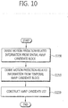
- Fig. 10 is a flowchart illustrating an inter prediction method using AMVP according to an embodiment of the present invention.
- motion prediction-related information is derived from spatial AMVP candidate blocks (step S1200).
- the spatial AMVP candidate block(s) may be derived from neighboring prediction blocks of the prediction target block.
- one of block A0 and block A1 may be used as a first spatial AMVP candidate block, and one of block B0, block B1, and block B2 may be used as a second spatial AMVP candidate block, thereby deriving the spatial AMVP candidate blocks.
- Motion prediction-related information is derived from a temporal AMVP candidate block (step S1210).
- the collocated block may be adaptively determined depending on the location of the prediction target block in the LCU so that the collocated block is included in same LCU together with the prediction target block.
- a method that the collocated block not included in same LCU together with the prediction target block may not be used, as well as a method that a collocated block is adaptively determined depending on the location of the prediction target block in the LCU to be present at a location included in same LCU together with the prediction target block, may be used.
- step S1200 of deriving the spatial AMVP candidate blocks when the first spatial AMVP candidate block and the second spatial AMVP candidate block are determined as available, and the derived motion prediction vector values are not the same, the step S1210 of deriving a temporal prediction motion vector may not be performed.
- An AMVP candidate list is constructed (step S1220).
- the AMVP candidate list is constructed by using the motion prediction-related information derived through at least one of steps S1200 and S1210. In case the same motion prediction-related information exists in the constructed AMVP candidate list, one value among the same motion prediction-related information may be used as an AMVP candidate value.
- the motion prediction-related information included in the AMVP candidate list may include a fixed number of candidate values only.
Abstract
Description
- The present invention relates to a video encoding and decoding method, and more specifically, the present invention pertains to a method for deriving a temporal prediction motion vector and an apparatus for using this method.
- In recent years, a demand for high-resolution, high-quality video, such as HD (High Definition) video and UHD (Ultra High Definition) video, has been increased in various areas. As video data comes to have high resolution and/or high quality, an amount of video data relatively goes up compared with existing video data, and thus, when the video data is transmitted via a conventional wired/wireless broadband network or is stored in an existing storage medium, costs for transmission and storage are increased. To address such problems that occur as video data goes to high resolution and high quality, high-efficiency video compression technologies may be utilized.
- A number of scheme have been introduced for a video compression, such as inter prediction scheme that predicts pixel values included in a current picture from a picture before or after the current picture, intra prediction scheme that predicts pixel values included in a current picture using pixel information in the current picture, and entropy encoding scheme that assigns a shorter codeword to a value that happens more frequently while assigning a longer codeword to a value that happens less frequently. Such video compression schemes may be utilized to effectively compress, transmit, or store video data.
- An object of the present invention is to provide a method of deriving a temporal prediction motion vector for a block adjoining with an LCU boundary.
- Another object of the present invention is to provide an apparatus of performing a method of deriving a temporal prediction motion vector for a block adjoining with an LCU boundary.
- To achieve the first object of the present invention, according to an aspect of the present invention, a video decoding method includes the steps of determining a reference picture index of a collocated block of a prediction target block; and determining a motion prediction vector of the collocated block, the collocated block is a block adaptively determined by a location of the prediction target block within a Largest Coding Unit (LCU). The collocated block may be differently determined by deciding whether a lower boundary of the prediction target block adjoins with an LCU boundary. The collocated block may be differently determined by deciding whether a lower boundary of the prediction target block adjoins with an LCU boundary and whether only a right boundary of the prediction target block adjoins with the LCU boundary. The collocated block may be determined by referencing positions of pixels within the LCU. If a left side or lower boundary of the prediction target block does not adjoin with the LCU boundary, a first collocated block and a fifth collocated block are sequentially determined as the collocated block according to an availability of the collocated block at a corresponding position.
- To achieve the second object of the present invention, according to an aspect of the present invention, a video decoding method may include the steps of determining whether a boundary of a prediction target block adjoins with a boundary of a LCU; and determining an availability of a first collocated block according to the determination of whether the boundary of the prediction target block adjoins with the boundary of the LCU. The video decoding method may further include the step of determining other collocated block except for the first collocated block as a collocated block to derive a temporal prediction motion vector if it is determined that the first collocated block is not available. The step of determining the other collocated block except for the first collocated block as the collocated block to derive the temporal prediction motion vector if the first collocated block is not available, is a step for determining different collocated blocks to derive the temporal prediction motion vector for a case where a lower boundary of the prediction target block adjoins with the boundary of the LCU and for a case where only a right boundary of the prediction target block adjoins with the boundary of the LCU. The step of determining the availability of the first collocated block according to the determination of whether the boundary of the prediction target block is adjoined with the boundary of the LCU, is a step for determining the first collocated block as unavailable if a lower boundary of the prediction target block adjoins with the boundary of the LCU. The step of determining the first collocated block as the collocated block to derive the temporal prediction motion vector if the first collocated block is available, or determining an availability of a fifth collocated block if the first collocated block is not available, may be further comprised.
- To achieve the third object of the present invention, according to an aspect of the present invention, a video decoding apparatus includes an entropy decoding unit that decodes LCU size information and a prediction unit that determines a reference picture index of a collocated block of a prediction target block and determines a motion prediction vector of the collocated block, wherein the collocated block is a block adaptively determined by a location of the prediction target block within an LCU. The collocated block may be differently determined by deciding whether a lower boundary of the prediction target block adjoins with an LCU boundary. The collocated block may be differently determined by deciding whether a lower boundary of the prediction target block adjoins with an LCU boundary and whether only a right boundary of the prediction target block adjoins with the LCU boundary. The collocated block may be determined by referencing positions of pixels within the LCU. If a left side or lower boundary of the prediction target block is not adjoined with the LCU boundary, a first collocated block and a fifth collocated block are sequentially determined as the collocated block according to an availability of the collocated block at a corresponding position.
- To achieve the fourth object of the present invention, according to an aspect of the present invention, a video decoding unit may include an entropy decoding unit that decodes LCU size information and a prediction unit that determines whether a boundary of a prediction target block adjoins with a boundary of an LCU and determines an availability of a first collocated block according to the determination of whether the boundary of the prediction target block adjoins with the boundary of the LCU. The prediction unit may determine other collocated block except for the first collocated block as a collocated block to derive a temporal prediction motion vector if it is determined that the first collocated block is not available. The prediction unit may determine different collocated blocks to derive the temporal prediction motion vector for a case where a lower boundary of the prediction target block adjoins with the boundary of the LCU and for a case where only a right boundary of the prediction target block adjoins with the boundary of the LCU. The prediction unit may determine the first collocated block as unavailable if a lower boundary of the prediction target block adjoins with the boundary of the LCU. The prediction unit may determine the first collocated block as the collocated block to derive the temporal prediction motion vector if the first collocated block is available, or may determine an availability of a fifth collocated block if the first collocated block is not available.
- As described above, the method of deriving a temporal prediction motion vector and an apparatus of using the method according to an embodiment of the present invention may differently use a collocated (or co-located or colocated) picture, from which a temporal motion vector derived, depending on whether a prediction target block adjoins an LCU. By using this method, the bandwidth of memory unnecessarily used to derive a temporal motion vector may be reduced and complexity in implementation may be minimized.
-
-
Fig. 1 is a block diagram illustrating a video encoding apparatus according to an embodiment of the present invention. -
Fig. 2 is a block diagram illustrating a video decoder according to another embodiment of the present invention. -
Fig. 3 is a conceptual view illustrating a method of deriving a temporal prediction motion vector according to an embodiment of the present invention. -
Fig. 4 is a flowchart illustrating a method of deriving a temporal prediction motion vector according to an embodiment of the present invention. -
Fig. 5 is a conceptual view illustrating a position of a collocated block to derive a temporal motion vector according to an embodiment of the present invention. -
Fig. 6 is a conceptual view illustrating a method of determining a collocated block to derive a motion prediction vector according to an embodiment of the present invention. -
Fig. 7 is a conceptual view illustrating a case where a prediction target block adjoins with a lower boundary of an LCU according to an embodiment of the present invention. -
Fig. 8 is a flowchart illustrating an inter prediction method using a merge mode according to an embodiment of the present invention. -
Fig. 9 is a conceptual view illustrating locations of spatial merging candidates according to an embodiment of the present invention. -
Fig. 10 is a flowchart illustrating an inter prediction method using AMVP according to an embodiment of the present invention. - Various modifications may be made to the present invention and the present invention may have a number of embodiments. Specific embodiments are described in detail with reference to the figures. However, the present invention is not limited to specific embodiments, and it should be understood that the present invention includes all modifications, equivalents, or replacements that are included in the spirit and technical scope of the present invention. Similar referencing marks may be used for between similar modules when the figures are explained.
- The terms "first" and "second" may be used to describe various components (or feature). However the components are not limited thereto. These terms are used only to distinguish one component from another. For example, the first component may be also named as the second component, and the second component may be similarly named as the first component. The term "and/or" includes a combination of a plurality of related items as described herein or any one of the plurality of related items.
- When a component (or feature) is "connected" or "coupled" to another component, the component may be directly connected or coupled to the other component. In contrast, when a component is "directly connected or coupled" to another component, no component intervenes.
- The terms used herein are given to describe the embodiments but not intended to limit the present invention. A singular term includes a plural term unless otherwise stated clearly in context. As used herein, the terms "include" or "have", etc. are used to indicate that there are features, numerals, steps, operations, components, parts or combinations thereof as described herein, but do not exclude the presence or possibility of addition of one or more features, numerals, steps, operations, components, parts or components thereof.
- Hereinafter, preferred embodiments of the present invention will be described in greater detail with reference to the accompanying drawings. The same reference numerals refer to the same components throughout the drawings, and the description of the same components is not repeated.
-
Fig. 1 is a block diagram illustrating a video encoding apparatus according to an embodiment of the present invention. - Referring to
Fig. 1 , the video encoding apparatus 100 may include apicture splitting module 110, aninter prediction module 120, anintra prediction module 125, atransform module 130, aquantization module 135, are-arrangement module 160, anentropy encoding module 165, adequantization module 140, aninverse transform module 145, afiltering module 150, and amemory 155. - Each module of
Fig. 1 are shown independently from each other to represent different functions from each other in the video encoding apparatus, but this does not mean that each module should be implemented in a separated hardware or software module (component) unit. That is, for convenience of description, the modules are shown to be provided independently, and at least two of the modules may be combined to constitute one module, or one of the modules may be divided into a plurality of modules to perform functions. Embodiments of combinations of the modules or embodiments of separation of the modules are also included in the scope of the present invention without departing from the gist of the present invention. - Further, some of the modules may be not essential modules that perform essential functions of the present invention but may be rather optional modules to enhance performance. The present invention may include only the essential modules necessary to implement the gist of the present invention excluding the modules merely used for better performance, and this structure is also included in the scope of the present invention.
- A
picture splitting module 110 may split an input picture into at least one processing unit. At this time, the processing unit may be a prediction unit (PU), a transform unit (TU), or a coding unit (CU). Thepicture splitting module 110 may encode the picture by splitting one picture into a combination of a plurality of coding units, prediction units, and transform units, and a combination of one coding unit, prediction unit and transform unit may be selected according to a predetermined standard (or reference) such as a cost function and may be encoded. - For example, one picture may be split into a plurality of coding units. A recursive tree structure, such as quad tree structure, may be used to split a picture into coding units. With a picture or a largest coding unit as a root, a coding unit may be split into other coding units as many child nodes as the number of the split coding units. The coding unit that is no more split due to a predetermined limitation is to be a leaf node. That is, assuming that only square-shape split is available for a coding unit, the coding unit may be split into a maximum of four other coding units.
- Hereinafter, in embodiments of the present invention, the coding unit may mean a unit in which decoding as well as encoding is performed.
- A prediction unit may be partitioned with a form of at least one square or rectangle having a same size within a coding unit.
- Upon generation of a prediction unit in which intra prediction is performed based on a coding unit, if the coding unit is not a smallest coding unit, intra prediction may be performed without splitting the prediction unit into a plurality of NxN prediction units.
- A prediction module may include an
inter prediction module 120 that performs an inter prediction and anintra prediction module 125 that performs an intra prediction. It may be determined whether to perform the inter prediction or intra prediction with respect to the prediction unit, and according to each prediction method, specific information (e.g., intra prediction mode, motion vector, reference picture, etc.) may be determined. At this time, a processing unit on which prediction is performed may differ from a processing unit on which the prediction method and its details are determined. For example, the prediction method and prediction mode may be determined by a prediction unit, and a performance of the prediction may be performed in a transform unit. A residual value (residual block) between a generated prediction block and an original block may be input to thetransform module 130. Further, the prediction mode information and motion vector information, etc. used for the prediction, together with the residual value, may be encoded in anentropy encoding module 165 and may be then transmitted to a decoding apparatus. If a specific encoding mode is used, rather than generating the prediction block by theprediction module - The inter prediction module may predict a prediction unit based on information of at least one picture among pictures prior to a current picture or pictures after the current picture. The inter prediction module may include a reference picture interpolation module, a motion prediction module, and a motion compensation module.
- The reference picture interpolation module may receive reference picture information from the
memory 155 and may generate pixel information in the unit of less than an integer pixel unit within the reference picture. In the case of luma pixels, a DCT-based 8 tap interpolation filter with different filter coefficients for each tap may be used to generate the pixel information in the unit of less than the integer pixel unit, a unit of 1/4 pixel. In the case of a chroma signal, a DCT-based 4 tap interpolation filter with different filter coefficients for each tap may be used to generate the pixel information in the unit of less than the integer pixel unit, a unit of 1/8 pixel. - A motion prediction module may perform motion prediction based on a reference picture interpolated by the reference picture interpolation module. To derive a motion vector, various methods may be used, such as FBMA (Full search-based Block Matching Algorithm), TSS (Three Step Search), NTS (New Three-Step Search Algorithm), etc. The motion vector may have a motion vector value in a 1/2 pixel unit or in a 1/4 pixel unit based on an interpolated pixel. The motion prediction module may predict a current prediction unit by applying various motion prediction method. As to the motion prediction method, various methods may be used, such as a skip method, a merge method, or an AMVP (Advanced Motion Vector Prediction) method.
- According to an embodiment of the present invention, the inter prediction module may determine whether a boundary of a prediction target block adjoins with a boundary of an LCU (Largest Coding Unit), and may determine whether a first collocated (or colocated or co-located) block is available according to the determination of whether the boundary of the prediction target block adjoins with the boundary of the LCU. For example, in case the first collocated block is not available, a second collocated block may be determined as a collocated block to derive a temporal prediction motion vector. Or in case the first collocated block is not available, a position of the first collocated block may be changed, and the position-changed first collocated block may be determined as a collocated block to derive a temporal prediction motion vector.
- Further, the inter prediction module may include a predicting module that determines a reference picture index of a collocated block of a prediction target block and determines a motion prediction vector of the collocated block. The collocated block may be adaptively determined according to a location of the prediction target block in the LCU (Largest Coding Unit). Hereinafter, the operation of the prediction module according to the present invention is described in detail.
- The inter prediction module may generate a prediction unit based on information on a reference pixel neighboring to the current block, which is pixel information on pixels in the current picture. In case the block neighboring to the current prediction unit is a block that inter prediction is applied to, and thus, the reference pixel is a pixel through the inter prediction, the reference pixel included in the block to which the inter prediction applied may be replaced with reference pixel information of a block to which the intra prediction applied. That is, in case a reference pixel is not available, the unavailable reference pixel information may be replaced with at least one of available reference pixels.
- As for the intra prediction, prediction modes may include a directional prediction mode in which reference pixel information is used according to a prediction direction and a non-directional mode in which, upon prediction, no directional information is used. A mode for predicting luma information may be different from a mode for predicting chroma information. Further, information on an intra prediction mode in which luma information has been predicted or predicted luma signal information may be utilized in order to predict chroma information.
- Upon performing the intra prediction, if the size of a prediction unit is the same as the size of a transform unit, the intra prediction is performed based on pixels located at the left side of the prediction unit, a pixel located at a top left of the prediction unit, and pixels located at top on the prediction unit. However, upon performing intra prediction, if the size of the prediction unit is different from the size of the transform unit, the intra prediction may be performed by using reference pixels based on the transform unit. Further, for a smallest coding unit only, the intra prediction may be performed by using NxN partition.
- In the intra prediction method, a prediction block may be generated after being applied with an MDIS (Mode Dependent Intra Smoothing) filter on reference pixels according to the prediction mode. Various types of AIS filters may be applicable to the reference pixels. To perform the intra prediction method, an intra prediction mode of a current prediction unit may be predicted from an intra prediction mode of a neighboring prediction unit of the current prediction unit. In case the prediction mode of the current prediction unit is predicted using the mode information predicted from the neighboring prediction unit, if the intra prediction mode of the current prediction unit is the same as the intra prediction mode of the neighboring prediction unit, predetermined flag information may be used to transmit information indicating that the current prediction unit is identical in the prediction mode to the neighboring prediction unit. And if the prediction mode of the current prediction unit is different from the prediction mode of the neighboring prediction unit, an entropy encoding may be performed to encode the prediction mode information of the current block.
- Further, a residual block may be derived, which includes information on a residual value that is a differential value between an original block of a prediction unit and a prediction unit on which prediction is performed based on the prediction unit generated in the
prediction module transform module 130. Thetransform module 130 may transform the residual block by a transform method, such as DCT (Discrete Cosine Transform) or DST (Discrete Sine Transform). The residual block includes residual information between the prediction unit generated through theprediction module - The
quantization module 135 may quantize values transformed into a frequency domain by thetransform module 130. A quantization parameter may vary depending on a block or importance of an image. A value produced from thequantization module 135 may be provided to thedequantization module 140 and there-arrangement module 160. - The
re-arrangement module 160 may perform re-arrangement of coefficients for the quantized residual value. - The
re-arrangement module 160 may change 2-dimensional (2D) block shaped coefficients to one-dimensional vector form through a coefficient scanning method. For example, there-arrangement module 160 may use a diagonal scanning method for scanning from DC coefficients to high-frequency coefficients, thereby arranging 2D block shaped coefficients into the form of a one-dimensional vector. Depending on the size of the transform unit and intra prediction mode, instead of the diagonal scanning method, a vertical scanning method in which 2D block shaped coefficients are scanned along a column direction or a horizontal scanning method in which 2D block shaped coefficients are scanned along a row direction may be used. In other words, one of the diagonal scanning, vertical scanning, and horizontal scanning may be used depending on the size of the transform unit and the intra prediction mode. - The
entropy encoding module 165 may perform an entropy encoding based on values produced by there-arrangement module 160. For the entropy encoding, various encoding methods, such as, e.g., Exponential Golomb, CABAC (Context-Adaptive Binary Arithmetic Coding), may be applied. - The
entropy encoding module 165 may encode various information, such as residual coefficient information and block type information of the coding unit, prediction mode information, partition unit information, prediction unit information and transmission unit information, motion vector information, reference frame information, interpolation information for a block, filtering information, and LCU size information, which are provided by there-arrange module 160 and theprediction module - The
entropy encoding module 165 may perform an entropy encoding on the coefficient values of the coding unit as an input from there-arrangement module 160 by using an entropy encoding method, such as CABAC. - The
dequantization module 140 may perform dequantization on the values quantized by thequantization module 135, and theinverse transform module 145 may perform inverse transform on the values transformed by thetransform module 130. The residual values generated by thedequantization module 140 and theinverse transform module 145 may be added with the prediction unit predicted through a motion estimation module, a motion compensation module and an intra prediction module included in theprediction module - A
filtering module 150 may include at least one of a deblocking filter, an offset correcting module, and an ALF (Adaptive Loop Filter). - A deblocking filter may remove a block distortion that is occurred due to a block boundary in the restored (or reconstructed) picture. Whether to apply the deblocking filter to a current block may be determined by a pixel included in several rows or columns included in blocks. In case that the deblocking filter is applied to the block, either a strong filter or a weak filter may be applied according to a necessary strength of the deblocking filtering. Further, in case that the deblocking filter is applied to the block, a horizontal direction filtering and a vertical direction filtering may be performed in parallel.
- An offset correcting module may correct an offset between an original picture and a picture applied with deblocking in a pixel unit (or a per-pixel basis). In order to perform the offset correction on a specific picture, pixels included in the picture are partitioned into a predetermined number of areas, one of which is then determined to perform an offset, and a method of applying an offset to the corresponding area or a method of applying an offset considering edge information of each pixel may be used.
- An ALF (Adaptive Loop Filter) may perform a filtering based on a value obtained by comparing a filtered reconstructed (or restored) picture with the original picture. Pixels included in a picture are partitioned into predetermined groups, and then, one filter to be applied to a corresponding group is determined to thereby perform filtering on each group in a discriminating way. With respect to information on whether to apply the ALF, a luma signal may be transmitted for each coding unit, and the size and coefficient of the ALF to be applied may vary for each block. The ALF may have various shapes, and the number of coefficients included in the filter may vary correspondingly. Filtering-related information of such ALF (e.g., filter coefficient information, ALF On/Off information, or filter shape information) may be transmitted, included in a predetermined parameter set of the bitstream.
- The
memory 155 may store the reconstructed block or picture generated through thefiltering module 150, and the stored reconstructed block or picture may be provided to theprediction module -
Fig. 2 is a block diagram illustrating a video decoder according to another embodiment of the present invention. - Referring to
Fig. 2 , the video decoder may include anentropy decoding module 210, are-arrangement module 215, adequantization module 220, aninverse transform module 225,prediction module filtering module 240, and amemory 245. - In case a video bitstream is input from the video encoder, the input bitstream may be decoded in a procedure opposite to that of the video encoder.
- The
entropy decoding module 210 may perform an entropy decoding in a procedure opposite to that of the entropy encoding performed in the entropy encoding module of the video encoder. Of the pieces of information decoded in theentropy decoding module 210, information used to derive a prediction block, such as LCU size information or block size information, is provided to theprediction module re-arrangement module 215. - The
entropy decoding module 210 may decode information relating to an intra prediction and an inter prediction performed in the encoder. As described above, in case there is a predetermined limitation when the video encoder performs the intra prediction and the inter prediction, the entropy decoding is performed based on such limitation to thereby receiving information relating to the intra prediction and inter prediction for the current block. - The
re-arrangement module 215 may perform a re-arrangement based on a method by the encoder for re-arranging a bitstream which is entropy decoded in theentropy decoding module 210. Such re-arrangement may be performed by restoring coefficients represented in the form of one-dimensional vectors to 2D block shape of coefficients. - The
dequantization module 220 may perform a dequantization based on the block of re-arranged coefficients and quantization parameters provided from the encoder. - The
inverse transform module 225 may perform an inverse DCT and an inverse DST, with respect to the DCT and DST which are performed by the transform module, on a result of the quantization performed in the video encoder. The inverse transform may be performed in basis of a transmission unit determined at the video encoder. The transforming module of the video encoder may selectively perform DCT and DST depending on a plurality of information, such as a prediction method, a size of a current block and a prediction direction, and theinverse transform module 225 of the video decoder may perform an inverse transform based on the transformed information performed by the transform module of the video encoder. - The
prediction module memory 245 and the prediction block generation-related information provided from theentropy decoding module 210. - The
prediction module - It may be determined which one of a skip mode, a merge mode, and an AMVP mode is a method of motion prediction for a prediction unit included in a corresponding coding unit, based on the coding unit, in order to perform inter prediction.
- According to an embodiment of the present invention, the inter prediction module may determine whether a prediction target block adjoins with a boundary of an LCU (Largest Coding Unit), and may determine whether a first collocated block is available according to the determination of whether the prediction target block adjoins with the boundary of the LCU. For example, if it is determined that the first collocated block is not available, a second collocated block may be determined as a collocated block to derive a temporal motion prediction vector, or if the first collocated block is not available, the position of the first collocated block may be changed such that the position-changed first collocated block may be determined as a collocated block to derive a temporal motion prediction vector. Further, the inter prediction module may include a predicting module that determines a reference picture index of a collocated block of the prediction target block and determines a motion prediction vector of the collocated block. The collocated block may be adaptively determined according to a location of the prediction target block in the LCU (Largest Coding Unit). Hereinafter, an operation of a prediction module according to the present invention is described in detail.
- The intra prediction module may generate a prediction block based on information of pixels in a current picture. In case the prediction unit is the one which the intra prediction is applied to, the intra prediction may be performed based on intra prediction mode information of the prediction unit provided from the video encoder. The intra prediction module may include an MDIS filter, a reference pixel interpolating module, and a DC filter. The MDIS filter performs a filtering on the reference pixels of the current block. For the MDIS filter, it may be determined whether to apply the filter according to the prediction mode of the current prediction unit. The filtering on the reference pixels of the current block may be performed using MDIS filter information and prediction mode of the prediction unit provided from the video encoder. In case the prediction mode of the current block is a mode in which filtering is not performed, the MDIS filter may not apply.
- In case that the prediction mode of the prediction unit is a prediction mode in which the intra prediction is performed based on the pixel values obtained by interpolating the reference pixel, the reference pixel with a unit less than an integer pixel may be derived by interpolating the reference pixels. In case that the prediction mode of the current prediction unit is a prediction mode in which the prediction block is generated without interpolating the reference pixels, the reference pixel may not be subjected to interpolation. The DC filter may generate a prediction block through the filtering, if the prediction mode of the current block is a DC mode.
- The reconstructed block or picture may be provided to the
filtering module 240. Thefiltering module 240 may include a deblocking filter, an offset correcting module, and an ALF. - Information on whether the corresponding block or picture has been applied with the deblocking filter may be provided from a video (or image) encoder. If the deblocking filter has been applied, information on whether the applied deblocking filter is a strong filter or a weak filter may be provided from the video encoder. The deblocking filter of the video decoder may receive deblocking filter-related information from the video encoder, and the deblocking filtering may be performed on the corresponding block in the video decoder. Like the video encoder, the video decoder may first perform a vertical deblocking filtering and a horizontal deblocking filtering. An overlapping portion(s) may be subjected to at least one of the vertical deblocking and horizontal deblocking. In the region where the vertical deblocking filtering and the horizontal deblocking filtering overlap each other, either of the vertical deblocking filtering or the horizontal deblocking filtering, which did not perform previously may be performed for this region. Such deblocking filtering process enables a parallel processing of the deblocking filtering.
- An offset correcting module may perform an offset correction on the reconstructed picture based on a type of the offset correction applied to the picture in an encoding process and information on offset value applied in the encoding process.
- An ALF may perform a filtering according to a comparison between the reconstructed picture after the filtering and the original picture. The ALF may be performed on a coding unit based on the information on whether the ALF is applied and ALF coefficient information, which are provided from the encoder. Such ALF information may be provided by included in a specific parameter set.
- The
memory 245 may store a reconstructed picture or a reconstructed block in order to use this as a reference picture or a reference block, and may provide the reconstructed picture to an display module. - As described above, even if a term of 'coding unit' is used in the embodiment of the present invention for convenience of description, the coding unit may be also used as a unit for decoding. Hereinafter, a the prediction method described below in connection with
Figs. 3 to 11 according to an embodiment of the present invention may be performed in a component, such as a predicting module as shown inFigs. 1 and2 . -
Fig. 3 is a conceptual view illustrating a method of deriving a temporal prediction motion vector according to an embodiment of the present invention. - Referring to
Fig. 3 , the temporal prediction motion vector may be derived based on a motion vector value of a collocated block (colPu) in a collocated picture (colPic). - The collocated picture is a picture including a collocated block for deriving temporal prediction motion related information upon performing the inter prediction method, such as a merge or AMVP. The collocated block may be defined as a block included in a collocated picture, and the collocated block is derived based on location information of a prediction target block and has a temporally different phase from the prediction target block.
- There may be a plurality of collocated blocks for one prediction target block. The motion related information of the collocated block included in the collocated picture may be stored as one representative value with respect to a predetermined unit. For example, with respect to a unit of 16x16 block size, motion prediction related information (motion vector, reference picture, etc.) may be determined and stored as one representative value in a 16x16 block unit.
-
Fig. 4 is a flowchart illustrating a method of deriving a temporal prediction motion vector according to an embodiment of the present invention. - Hereinafter, the method of deriving a temporal prediction motion vector, which is to be described below, may be used in an inter prediction method such as merge mode or AMVP mode. The method of deriving the temporal prediction motion vector may be a method of deriving a temporal candidate block (collocated block) for performing merge mode, a method of deriving a temporal candidate block (collocated block) for performing AMVP mode, and a method of deriving a temporal prediction motion vector.
- Hereinafter, in an embodiment of the present invention, the collocated block may be defined and used as a term indicating a temporal candidate block used in the merge mode and AMVP mode.
- Referring to
Fig. 4 , collocated picture information is derived (step S400). - Location information of a prediction target block, size information of the prediction target block, and reference picture index information of the prediction target block may be used to derive collocated picture information, collocated block information and temporal prediction motion vector.
- According to an embodiment of the present invention, the collocated picture information may be derived based on slice type information (slice_type), reference picture list information (collocated_from_10_flag), and reference picture index information (collocated_ref_idx). Using the the reference picture list information (collocated_from_10_flag), if the reference picture list information (collocated_from_10_flag) indicates 1, it represents that the collocated picture is included in a first reference picture list (List 0), and if the reference picture list information (collocated_from_10_flag) indicates 0, it represents that the collocated picture is included in a second reference picture list (List 1).
- For example, in case the slice type is slice B and a value of the reference picture list information (collocated_from_10_flag) is 0, the collocated picture may be determined as a picture included in the first reference picture list, and in case the slice type is slice B and a value of the reference picture list information (collocated_from_10_flag) is 1 or in case the slice type is slice P, the collocated picture may be determined as a picture included in the second reference picture list.
- In the case of an inter prediction method using a merge mode, if a predetermined condition is met, reference picture index information of a neighboring block at a specific position may be determined as information for collocated picture, and if the predetermined condition is not met, a previous picture of a current picture may be determined as collocated picture information.
- Information for collocated block is derived (step S410).
- The information for collocated block may be differently derived depending on whether part (or portion) of a prediction target block adjoins with a boundary of an LCU (Largest Coding Unit). Hereinafter, a method of determining a collocated block depending on the location of a prediction target block and the boundary of an LCU is described with reference to
Figs. 5 to 9 . -
Fig. 5 is a conceptual view illustrating a location of a collocated block to derive a temporal motion vector according to an embodiment of the present invention. - Referring to
Fig. 5 , blocks at various positions with respect to a prediction target block may be used as collocated blocks to derive a temporal motion vector. The collocated blocks that may be used to derive the temporal motion vector may be classified depending on the locations as follows. - In case a point located at a top-left of a prediction target block is at (xP, yP), the width of the prediction target block is nPSW, and the height of the prediction target block is nPSH, a first collocated
block 500 may be a block including a point (xP+nPSW, yP+nPSH) in the collocated picture, a second collocatedblock 510 may be a block including a point (xP+nPSW-MinPuSize, yP+nPSH) in the collocated picture, a third collocatedblock 520 may be a block including a point (xP+nPSW, yP+nPSH-MinPuSize) in the collocated picture, a fourth collocatedblock 530 may be a block including a point (xP+nPSW-1, yP+nPSH-1) in the collocated picture, a fifth collocatedblock 540 may be a block including a point (xP+(nPSW>>1), yP+(nPSH>>1)) in the collocated picture, and a sixth collocatedblock 550 may be a block including a point (xP+(nPSW>>1)-1, yP+(nPSH>>1)-1) in the collocated picture. - The collocated block may be adaptively determined according to a position of a current prediction unit located within in the LCU. A positional relationship between a prediction target block and a boundary of the LCU may be categorized in the following cases: 1) where a lower end and a right side of the prediction target block do not adjoin with the LCU boundary, 2) where only the lower end of the prediction target block adjoins with the LCU boundary, 3) where both the right side and the lower end of the prediction target block adjoin with the LCU boundary, and 4) where only the right side of the prediction target block adjoins with the LCU boundary.
- According to an embodiment of the present invention, the collocated block may be adaptively determined in a different way depending on the location of the prediction target block in the LCU.
- 1) In case that the lower end and right side of the prediction target block do not adjoin with the LCU boundary, the first collocated block and the fifth collocated block may be sequentially used as a collocated block with an availability check in order to derive a temporal motion vector.
- 2) In case that only the lower end of the prediction target block adjoins with the LCU boundary, the third collocated block and the fifth collocated block may be sequentially used as a collocated block with the availability check in order to derive a temporal motion vector.
- 3) In case that both the right side and lower end of the prediction target block adjoin with the LCU boundary, the fourth collocated block and the fifth collocated block may be sequentially used as a collocated block with the availability check in order to derive a temporal motion vector.
- 4) In case that only the right side of the prediction target block adjoins with the LCU boundary, the second collocated block and the fifth collocated block may be sequentially used as a collocated block with the availability check in order to derive a temporal motion vector.
- That is, according to an embodiment of the present invention, depending on the location of the current block in the LCU, a temporal candidate block may be adaptively determined. The positions of pixels to specify a temporal candidate block for a case when the lower boundary of the current block adjoins with the LCU boundary may be different from the positions of pixels to specify a temporal candidate block for a case when the lower boundary of the current block does not adjoin with the LCU boundary. And, the positions of pixels to specify a temporal candidate block for a case when the lower boundary of the current block adjoins with the LCU boundary may be different from the positions of pixels to specify a temporal candidate block for a case when only the right boundary of the current block adjoins with the LCU boundary.
- According to another embodiment of the present invention, a method may be used, in which a collocated block may be determined (or selected) adaptively and differently depending on the position of the prediction target block in the LCU such that the collocated block and the prediction target block are located within same LCU, or the collocated block may not be used if the collocated block and the target prediction block are not located within same LCU.
-
Fig. 6 is a conceptual view illustrating a method of determining a collocated block to derive a motion prediction vector according to an embodiment of the present invention. - Referring to
Fig. 6 , the positions of collocated blocks of a plurality of prediction units included in one LCU may be known. - For the cases of PU0, PU1, PU2, and PU5, the prediction units are prediction units inside of the LCU, and the first collocated block may be firstly used as a collocated lock to derive a temporal motion vector.
- For the cases of PU4 and PU7, the boundaries of the prediction units adjoin with only the lower boundary of the LCU, and the third collocated block may be firstly used as collocated block to derive a temporal motion vector.
- For the case of PU8, the boundary of the prediction unit adjoins with both the lower boundary and the right boundary of the LCU, and the fourth collocated block may be firstly used as a collocated block to derive a temporal motion vector.
- For the cases of PU3 and PU6, the boundaries of the prediction units adjoin with only the right boundary of the LCU, and the second collocated block may be firstly used as a collocated block to derive a temporal motion vector.
- That is, as described above, a temporal candidate block is adaptively determined depending on the location of the current block in the LCU, and the positions of pixels to specify a temporal candidate block for cases when the lower boundary of the current block adjoins with the LCU boundary (cases of PU4, PU7 and PU8) and for cases when the lower boundary of the current block does not adjoin with the LCU boundary (cases of PU0, PU1, PU2, PU3, PU5, and PU6) are different from each other. Further, the positions of pixels to specify a temporal candidate block may be different for cases when the lower boundary of the current block adjoins with the LCU boundary (cases of PU4, PU7, and PU8) and for cases when only the right boundary of the current block adjoins with the LCU boundary (cases of PU3 and PU6).
- According to another embodiment of the present invention, as long as a collocated block is located within same LCU together with the prediction target block, the collocated block is adaptively and differently determined depending on the location of the prediction target block in the LCU. If a specific collocated block is not located within same LCU together with the prediction target block, such specific collocated block may be not available. For example, if the lower boundary of a prediction block adjoins with the lower boundary of the LCU like PU4, PU7, and PU8, the first collocated block may be marked (or indicated) as unavailable, and the fifth collocated block may be used instead as a collocated block to derive a temporal prediction vector.
- As such, as a method of deriving a collocated block, a method may be used that, categorizing characteristics of a prediction target block as described above depending on the location of the prediction target block and LCU boundary, selects a block to be used as a collocated block depending on the categorized location of the prediction target block. Preferably, it is assumed that the first collocated block and the fifth collocated block may be sequentially used as a collocated block to derive a temporal motion vector. After checking an availability of the first collocated block (for example, whether the lower boundary of the prediction target block adjoins with the LCU), a collocated block other than the first collocated block may be determined as a collocated block to derive a temporal motion vector. For example, if the first collocated block is determined as unavailable through steps of determining whether the prediction target block adjoins with the boundary of the LCU (Largest Coding Unit), the collocated block to derive a temporal motion vector may be changed to other collocated block (e.g., third collocated block), or the fifth collocated block may be used directly without using the first collocated block.
- Specifically, the above method may be performed through the following steps:
- 1) Step of determining whether the boundary of the prediction target block adjoins with the boundary of the LCU (Largest Coding Unit),
- 2) Step of determining whether the first collocated block is available depending on whether the boundary of the prediction target block adjoins with the LCU boundary. Specifically in step 2), when the lower boundary of the prediction target block adjoins with the LCU boundary, it may be determined that the first collocated block is not available,
- 3) Step of determining a collocated block other than the first collocated block as a collocated block to derive a temporal prediction motion vector when the first collocated block is not available. Specifically, in step 3), for a case that the lower boundary of the prediction target block adjoins with the LCU boundary and for a case that the right boundary of the prediction target block adjoins with the LCU boundary, different collocated blocks for each different case may be determined as collocated blocks to derive a temporal prediction motion vector ,
- 4) Step of determining the first collocated block as a collocated block to derive a temporal prediction motion vector if the first collocated block is available, and determining an availability of the fifth collocated block if the first collocated block is not available.
- The above steps may be optional steps, and the sequential relationship of the steps or the method of the determination may be changed without departing from the gist of the present invention.
-
Fig. 7 is a conceptual view illustrating a case where a prediction target block adjoins with a lower boundary of an LCU according to an embodiment of the present invention. - Referring to
Fig. 7 , a case is shown that the location of the collocated block is changed when the prediction target block (PU, PU7, or PU8) is located at the lower boundary of the LCU. In case the prediction target block (PU4, PU7, or PU8) is located at the lower boundary of the LCU, the location of the collocated block may be set so that the motion prediction-related information may be derived even without searching an LCU positioned under a current LCU among LCUs. For example, a temporal prediction motion vector may be derived by using the third collocated block rather than the first collocated block of the prediction target block. 1) in case that only the right boundary of the LCU is adjoined, depending on availability, the first collocated block and the fifth collocated block are sequentially determined as a collocated block to derive a temporal prediction motion vector, 2) in case that the lower boundary of the LCU is adjoined, depending on availability, the third collocated block and the fifth collocated block may be sequentially determined as a collocated block to derive a temporal prediction motion vector. That is, according to an embodiment of the present invention, the positions of pixels to specify a temporal candidate block may be different for a case when the lower boundary of the current block adjoins with the LCU boundary and for a case when the lower boundary of the current block does not adjoin with the LCU boundary. - Referring back to
Fig. 4 , based on the collocated block determined through the method described above in connection withFigs. 5 to 7 , a collocated block motion prediction vector (mvLXCol) and collocated block availability information (availableFlagLXCol) are derived(step S420). - The collocated block availability information (availableFlagLXCol) and motion vector (mvLXCol) of the collocated block, which is to be used for inter prediction of the prediction target block based on the collocated block information determined through the processes shown in
Figs. 5 to 7 , may be derived by the following method: - 1) If the collocated block (colPu) is encoded based on an intra prediction mode, if the collocated block (colPu) is not available, if the collocated picture (colPic) is not available for predicting a temporal prediction motion vector, or if inter prediction is performed without using a temporal prediction motion vector, the collocated block motion vector (mvLXCol) and the collocated block availability information (availableFlagLXCol) may be set as 0.
- 2) Other than the case 1), the collocated block motion vector information (mvLXCol) and the collocated block availability information (availableFlagLXCol) may be derived through a flag (PredFlagL0) and a flag (PredFlagL1), where the flag (PredFlagL0) indicates whether L0 list is used or not, and the flag (PredFlagL1) indicates whether L1 list is used or not.
- First, if it is determined that the inter prediction has been performed on the collocated block without using list L0 (the flag (PredFlagL0) is equal to 0), motion prediction-related information of the collocated block, such as mvCol information, refldxCol information, and listCol information, may be set as L1 and MvL1[xPCol][yPCol], RefIdxL1[xPCol][yPCol], which are motion prediction-related information of the collocated block derived by using list L1, and the collocated block availability information (availableFlagLXCol) may be set as 1.
- In other cases, if it is determined that inter prediction has been performed on collocated block using list L0 (the flag (PredFlagL0) is equal to 1), motion prediction-related information of the collocated block, such as mvCol information, refldxCol information, and listCol information, may be set separately for a case where PredFlagL1 is 0 and for a case where PredFlagL1 is 1, and the collocated block availability information (availableFlagLXCol) may be set as 1.
- The derived mvLXCol is scaled (step S430).
- To use the mvLXCol derived through step S420 as a temporal prediction motion vector of the prediction target block, a derived mvLXCol value may be scaled based on distance information relating to a distance between the collocated picture including the collocated block and the collocated block reference picture referred by the collocated block and a distance between the picture including the prediction target block and a reference picture referred by the prediction target block. After the derived mvLXCol value is scaled, the temporal prediction motion vector can be derived.
- Hereinafter, according to an embodiment of the present invention, a method of performing an inter prediction, such as merge and AMVP, is described.
-
Fig. 8 is a flowchart illustrating an inter prediction method using a merge mode according to an embodiment of the present invention. - Referring to
Fig. 8 , motion prediction-related information may be derived from a spatial merging candidate (step S1000). - The spatial merging candidate may be derived from neighboring prediction units of a prediction target block. To derive the spatial merging candidate, information on the width and height of the prediction unit, MER (Motion Estimation Region) information, singleMCLFlag information, and partition position information may be received. Based on such input information, availability information (availableFlagN) according to the position of the spatial merging candidate, reference picture information (refldxL0, refldxL1), list utilization information (predFlagL0N, redFlagL1N), and motion vector information (mvL0N, mvL1N) may be derived. A plurality of blocks neighboring to the prediction target block may be spatial merging candidates.
-
Fig. 9 is a conceptual view illustrating positions of spatial merging candidates according to an embodiment of the present invention. - Referring to
Fig. 9 , in case that a location of a point at a top-left of the prediction target block is (xP, yP), a width of the prediction target block is nPSW, and a width of the prediction target block is nPSH, the spatial merging candidates may be a block A0 including the point (xP-1, yP+nPSH), a block A1 including the point (xP-1, yP+nPSH-MinPuSize), a block B0 including the point (xP+nPSW, yP-1), a block B1 including the point (xP+nPSW-MinPuSize, yP-1), and a block B2 including the point (xP-MinPuSize, yP-1). - Referring back to
Fig. 8 , a reference picture index value of the temporal merging candidate is derived (step S1010). - The reference picture index value of the temporal merging candidate, as an index value of a collocated picture including the temporal merging candidate (collocated block), may be derived through specific conditions as follows. The following conditions are arbitrary and may vary. For example, in case that a location of point at a top-left of the prediction target block is (xP, yP), the width of the prediction target block is nPSW, and the width of the prediction target block is nPSH, when 1) there exists a neighboring prediction unit of the prediction target block corresponding to position (xP-1, yP+nPSH-1) (hereinafter, referred to as a reference picture index derivation neighboring prediction unit), 2) the partition index value of the reference picture index derivation neighboring prediction unit is 0, 3) the reference picture index derivation neighboring prediction unit is not a block on which prediction performed using an intra prediction mode, and 4) the prediction target block and the reference picture index derivation neighboring prediction block do not belong to the same MER (Motion Estimation Region), the reference picture index value of the temporal merging candidate may be determined as the same value as the reference picture index value of the reference picture index derivation neighboring prediction unit. In the case of failing to satisfy these conditions, the reference picture index value of the temporal merging candidate may be set as 0.
- The temporal merging candidate block (collocated block) is determined, and motion prediction-related information is derived from the collocated block (step S1020).
- According to an embodiment of the present invention, the temporal merging candidate block (collocated block) may be adaptively determined depending on the location of the prediction target block in the LCU so that the collocated block is included in the same LCU together with the prediction target block.
- 1) In case that the lower end and the right side of the prediction target block do not adjoin with the LCU boundary, determining an availability, the first collocated block and the fifth collocated block may be sequentially used as a collocated block to derive a temporal motion vector.
- 2) In case that only the lower end of the prediction target block adjoins with the LCU boundary, determining an availability, the third collocated block and the fifth collocated block may be sequentially used as a collocated block to derive a temporal motion vector.
- 3) In case that both the right side and the lower end of the prediction target block adjoin with the LCU boundary, determining an availability, and the fourth collocated block and the fifth collocated block may be sequentially used as collocated blocks to induce a temporal motion vector.
- 4) In case only the right side of the prediction target block is adjacent to the LCU boundary, availability is determined, and the second collocated block and the fifth collocated block may be sequentially used as collocated blocks to induce a temporal motion vector.
- According to an embodiment of the present invention, a method may be used that enables a collocated block to be adaptively and differently determined depending on the position of the prediction target block in the LCU to be present at a position included in one LCU together with the prediction target block, or the collocated block not included in one LCU together with the prediction target block may not be used.
- As described above, as a method of producing a collocated block, a method may be used of separating characteristics of a prediction target block as described above depending on the position of the prediction target block and LCU boundary and determining a block to be immediately used as a collocated block depending on the position of the separated prediction target block. However, the first collocated block and the fifth collocated block may be first assumed to be sequentially used as collocated blocks to induce a temporal motion vector, whether the first collocated block is available (for example, whether the lower boundary of the prediction target block is adjacent to the LCU) is determined, and then, a collocated block other than the first collocated block may be determined as a collocated block to induce a temporal motion vector.
- A merge candidate list is configured (step S1030).
- The merging candidate list may be constructed to include at least one of spatial merging candidates and a temporal merging candidate. The spatial merging candidates and temporal merging candidate included in the merging candidate list may be arranged with a predetermined priority.
- The merging candidate list may be constructed to have a fixed number of merging candidates, and if the number of merging candidates is less than the fixed number, the motion prediction-related information owned by the merging candidates is combined to generate merging candidates or zero vectors are generated as merging candidates, thereby generating the merging candidate list.
-
Fig. 10 is a flowchart illustrating an inter prediction method using AMVP according to an embodiment of the present invention. - Referring to
Fig. 10 , motion prediction-related information is derived from spatial AMVP candidate blocks (step S1200). - To derive the reference picture index information and a prediction motion vector of the prediction target block, the spatial AMVP candidate block(s) may be derived from neighboring prediction blocks of the prediction target block.
- Referring back to
Fig. 9 , one of block A0 and block A1 may be used as a first spatial AMVP candidate block, and one of block B0, block B1, and block B2 may be used as a second spatial AMVP candidate block, thereby deriving the spatial AMVP candidate blocks. - Motion prediction-related information is derived from a temporal AMVP candidate block (step S1210).
- According to an embodiment of the present invention, the collocated block may be adaptively determined depending on the location of the prediction target block in the LCU so that the collocated block is included in same LCU together with the prediction target block.
- 1) In case that the lower end and the right side of the prediction target block do not adjoin with the LCU boundary, the first collocated block and the fifth collocated block may be sequentially used as a collocated block to derive a temporal motion vector with an availability check.
- 2) In case that only the lower end of the prediction target block adjoins with the LCU boundary, the third collocated block and the fifth collocated block may be sequentially used as a collocated block to derive a temporal motion vector with an availability check.
- 3) In case that both the right side and the lower end of the prediction target block adjoin with the LCU boundary, the fourth collocated block and the fifth collocated block may be sequentially used as a collocated block to derive a temporal motion vector with an availability check.
- 4) In case that only the right side of the prediction target block adjoins with the LCU boundary, the second collocated block and the fifth collocated block may be sequentially used as a collocated block to derive a temporal motion vector with an availability check.
- According to an embodiment of the present invention, a method that the collocated block not included in same LCU together with the prediction target block may not be used, as well as a method that a collocated block is adaptively determined depending on the location of the prediction target block in the LCU to be present at a location included in same LCU together with the prediction target block, may be used.
- In the step S1200 of deriving the spatial AMVP candidate blocks, when the first spatial AMVP candidate block and the second spatial AMVP candidate block are determined as available, and the derived motion prediction vector values are not the same, the step S1210 of deriving a temporal prediction motion vector may not be performed.
- An AMVP candidate list is constructed (step S1220).
- The AMVP candidate list is constructed by using the motion prediction-related information derived through at least one of steps S1200 and S1210. In case the same motion prediction-related information exists in the constructed AMVP candidate list, one value among the same motion prediction-related information may be used as an AMVP candidate value. The motion prediction-related information included in the AMVP candidate list may include a fixed number of candidate values only.
- Although the embodiments of the present invention have been described thus far, it may be understood by those skilled in the art to which the present invention pertains that various modifications and variations may be made to the present invention without departing from the spirit and scope of the present invention.
This application discloses the following apparatus, methods and systems: - 1. A method of deriving a candidate motion prediction vector, the method comprising:
- determining a reference picture index of a collocated block of a prediction target block; and
- determining a motion prediction vector of the collocated block,
- wherein the collocated block is a block adaptively determined by a location of the prediction target block within a Largest Coding Unit (LCU).
- 2. The method of clause 1, wherein the collocated block is differently determined by deciding whether a lower boundary of the prediction target block adjoins with an LCU boundary.
- 3. The method of clause 1, wherein the collocated block is differently determined by deciding whether a lower boundary of the prediction target block adjoins with an LCU boundary and whether only a right boundary of the prediction target block adjoins with the LCU boundary.
- 4. The method of clause 1, wherein the collocated block is determined by referencing positions of pixels within the LCU.
- 5. The method of clause 1, wherein if a left side or lower boundary of the prediction target block does not adjoined with the LCU boundary, a first collocated block and a fifth collocated block are sequentially determined as the collocated block according to an availability of the collocated block at a corresponding position, and
- wherein if a location of a point at a top-left of the prediction target block is (xP, yP), a width of the prediction target block is nPSW, and a height of the prediction target block is nPSH, the first collocated block is a block including a point at (xP+nPSW, yP+nPSH) within a collocated picture, and the fifth collocated block is a block including a point at (xP+(nPSW>>1), yP+(nPSH>>1)) within the collocated picture.
- 6. A method of deriving a candidate motion prediction vector, the method comprising:
- determining whether a boundary of a prediction target block adjoins with a boundary of a Largest Coding Unit (LCU); and
- determining an availability of a first collocated block according to the determination of whether the boundary of the prediction target block adjoins with the boundary of the LCU.
- 7. The method of clause 6, further comprising: if it is determined that the first collocated block is not available, determining other collocated block except for the first collocated block as a collocated block to derive a temporal prediction motion vector.
- 8. The method of clause 7, wherein the step of determining the other collocated block except for the first collocated block as the collocated block to derive the temporal prediction motion vector if the first collocated block is not available, is a step for determining different collocated blocks to derive the temporal prediction motion vector for a case where a lower boundary of the prediction target block adjoins with the boundary of the LCU and for a case where only a right boundary of the prediction target block adjoins with the boundary of the LCU.
- 9. The method of clause 6, wherein the step of determining the availability of the first collocated block according to the determination of whether the boundary of the prediction target block is adjoined with the boundary of the LCU, is a step for determining the first collocated block as unavailable if a lower boundary of the prediction target block adjoins with the boundary of the LCU.
- 10. The method of clause 6, further comprising the step of determining the first collocated block as the collocated block to derive the temporal prediction motion vector if the first collocated block is available, or determining an availability of a fifth collocated block if the first collocated block is not available ,
- wherein if a location of a point at a top-left of the prediction target block is (xP, yP), a width of the prediction target block is nPSW, and a height of the prediction target block is nPSH, the first collocated block is a block including a point (xP+nPSW, yP+nPSH) within a collocated picture, and the fifth collocated block is a block including a point (xP+(nPSW>>1), yP+(nPSH>>1)) within the collocated picture.
- 11. A video decoding apparatus, the apparatus comprising:
- an entropy decoding unit that decodes LCU size information; and
- a prediction unit that determines a reference picture index of a collocated block of a prediction target block and determines a motion prediction vector of the collocated block, wherein the collocated block is a block adaptively determined by a location of the prediction target block within a Largest Coding Unit (LCU).
- 12. The apparatus of clause 11, wherein the collocated block is differently determined by deciding whether a lower boundary of the prediction target block adjoins with an LCU boundary.
- 13. The apparatus of clause 11, wherein the collocated block is differently determined by deciding whether a lower boundary of the prediction target block adjoins with an LCU boundary and whether only a right boundary of the prediction target block adjoins with the LCU boundary.
- 14. The apparatus of clause 11, wherein the collocated block is determined by referencing positions of pixels within the LCU.
- 15. The apparatus of clause 11, wherein if a left side or lower boundary of the prediction target block is not adjoined with the LCU boundary, a first collocated block and a fifth collocated block are sequentially determined as the collocated block according to an availability of the collocated block at a corresponding position, and
- wherein if a location of a point at a top-left of the prediction target block is (xP, yP), a width of the prediction target block is nPSW, and a height of the prediction target block is nPSH, the first collocated block is a block including a point (xP+nPSW, yP+nPSH) within a collocated picture, and the fifth collocated block is a block including a point (xP+(nPSW>>1), yP+(nPSH>>1)) within the collocated picture.
- 16. A video decoding apparatus, the apparatus comprising:
- an entropy decoding unit that decodes LCU size information; and
- a prediction unit that determines whether a boundary of a prediction target block adjoins with a boundary of a Largest Coding Unit (LCU) and determines an availability of a first collocated block according to the determination of whether the boundary of the prediction target block adjoins with the boundary of the LCU.
- 17. The apparatus of clause 16, wherein the prediction unit determines other collocated block except for the first collocated block as a collocated block to derive a temporal prediction motion vector if it is determined that the first collocated block is not available.
- 18. The apparatus of clause 17, wherein the prediction unit determines different collocated blocks to derive the temporal prediction motion vector for a case where a lower boundary of the prediction target block adjoins with the boundary of the LCU and for a case where only a right boundary of the prediction target block adjoins with the boundary of the LCU.
- 19. The apparatus of clause 16, wherein the prediction unit determines the first collocated block as unavailable if a lower boundary of the prediction target block adjoins with the boundary of the LCU.
- 20. The apparatus of clause 16, wherein the prediction unit determines the first collocated block as the collocated block to derive the temporal prediction motion vector if the first collocated block is available, or determines an availability of a fifth collocated block if the first collocated block is not available, and
- wherein if a location of a point at a top-left of the prediction target block is (xP, yP), a width of the prediction target block is nPSW, and a height of the prediction target block is nPSH, the first collocated block is a block including a point (xP+nPSW, yP+nPSH) within a collocated picture, and the fifth collocated block is a block including a point (xP+(nPSW>>1), yP+(nPSH>>1)) within the collocated picture.
Claims (5)
- A method of decoding a video signal, comprising:deriving reference picture index information relating to a prediction target block from video data which is received and stored in a memory, the reference picture index information being used to determine a collocated picture comprising a collocated block relating to the prediction target block;determining a temporal prediction motion vector of the prediction target block by scaling a motion vector of the collocated block in the collocated picture;generating a motion vector candidate list including the temporal prediction motion vector; andperforming inter-prediction of the prediction target block based on the generated motion vector candidate list.
- The method of claim 1, wherein:the motion vector of the collocated block is scaled based on a temporal distance between the picture including the prediction target block and a reference picture referred by the prediction target block.
- The method of claim 1, wherein:the motion vector of the collocated block is scaled based on a temporal distance between the collocated picture including the collocated block and a collocated block reference picture referred by the collocated block.
- The method of claim 1, wherein:the motion vector of the collocated block is scaled based on a first and second distance;the first distance being a temporal distance between the picture including the prediction target block and a reference picture referred by the prediction target block; andthe second distance being a temporal distance between the collocated picture including the collocated block and a collocated block reference picture referred by the collocated block.
- The method of claim 1, wherein:the collocated block is determined based on an availability of a first collocated block included in the collocated picture, the first collocated block including a position corresponding to a lower end of and the right side of the current block; andwherein when a lower boundary of the prediction target block adjoins a lower boundary of a Largest Coding Unit (LCU), the first collocated block is determined unavailable and a second collocated block in the collocated picture is determined to be the collocated block, the second collocated block including a position corresponding to a central position of the current block.
Applications Claiming Priority (4)
| Application Number | Priority Date | Filing Date | Title |
|---|---|---|---|
| KR20110091782 | 2011-09-09 | ||
| KR1020120039501A KR101204026B1 (en) | 2011-09-09 | 2012-04-17 | Methods of derivation of temporal motion vector predictor and apparatuses for using the same |
| PCT/KR2012/007174 WO2013036041A2 (en) | 2011-09-09 | 2012-09-06 | Method for deriving a temporal predictive motion vector, and apparatus using the method |
| EP12829566.4A EP2672710B1 (en) | 2011-09-09 | 2012-09-06 | Method for deriving a temporal predictive motion vector, and apparatus using the method |
Related Parent Applications (2)
| Application Number | Title | Priority Date | Filing Date |
|---|---|---|---|
| EP12829566.4A Division EP2672710B1 (en) | 2011-09-09 | 2012-09-06 | Method for deriving a temporal predictive motion vector, and apparatus using the method |
| EP12829566.4A Division-Into EP2672710B1 (en) | 2011-09-09 | 2012-09-06 | Method for deriving a temporal predictive motion vector, and apparatus using the method |
Publications (2)
| Publication Number | Publication Date |
|---|---|
| EP3179723A1 true EP3179723A1 (en) | 2017-06-14 |
| EP3179723B1 EP3179723B1 (en) | 2023-01-25 |
Family
ID=47832709
Family Applications (2)
| Application Number | Title | Priority Date | Filing Date |
|---|---|---|---|
| EP17153707.9A Active EP3179723B1 (en) | 2011-09-09 | 2012-09-06 | Method for deriving a temporal predictive motion vector, and apparatus using the method |
| EP12829566.4A Active EP2672710B1 (en) | 2011-09-09 | 2012-09-06 | Method for deriving a temporal predictive motion vector, and apparatus using the method |
Family Applications After (1)
| Application Number | Title | Priority Date | Filing Date |
|---|---|---|---|
| EP12829566.4A Active EP2672710B1 (en) | 2011-09-09 | 2012-09-06 | Method for deriving a temporal predictive motion vector, and apparatus using the method |
Country Status (14)
| Country | Link |
|---|---|
| US (4) | US10523967B2 (en) |
| EP (2) | EP3179723B1 (en) |
| JP (7) | JP5745693B2 (en) |
| CN (19) | CN107635140B (en) |
| AU (1) | AU2012305071B2 (en) |
| BR (1) | BR112013022641B1 (en) |
| CA (2) | CA2829114C (en) |
| ES (1) | ES2487993B1 (en) |
| GB (7) | GB2559227B (en) |
| MX (4) | MX2013010155A (en) |
| PL (1) | PL231159B1 (en) |
| RU (10) | RU2622849C1 (en) |
| SE (5) | SE538787C2 (en) |
| WO (1) | WO2013036041A2 (en) |
Families Citing this family (49)
| Publication number | Priority date | Publication date | Assignee | Title |
|---|---|---|---|---|
| JP2014501091A (en) | 2010-12-17 | 2014-01-16 | エレクトロニクス アンド テレコミュニケーションズ リサーチ インスチチュート | Inter prediction method and apparatus |
| RU2622849C1 (en) * | 2011-09-09 | 2017-06-20 | Кт Корпорейшен | Method and device for decoding video signal |
| RU2694018C2 (en) * | 2011-09-23 | 2019-07-08 | Кт Корпорейшен | Video decoding method |
| WO2015016536A1 (en) * | 2013-07-30 | 2015-02-05 | 주식회사 케이티 | Image encoding and decoding method supporting plurality of layers and apparatus using same |
| CN105453562B (en) | 2013-07-30 | 2018-12-25 | 株式会社Kt | Support multiple layers of image coding and decoding method and the device using this method |
| CN105453563B (en) | 2013-07-30 | 2019-08-16 | 株式会社Kt | Support multiple layers of image coding and decoding method and the device using this method |
| CN112584140A (en) * | 2014-11-27 | 2021-03-30 | 株式会社Kt | Method for decoding or encoding a video signal |
| WO2017008255A1 (en) * | 2015-07-14 | 2017-01-19 | Mediatek Singapore Pte. Ltd. | Advanced intra prediction mode signaling in video coding |
| US10313765B2 (en) | 2015-09-04 | 2019-06-04 | At&T Intellectual Property I, L.P. | Selective communication of a vector graphics format version of a video content item |
| WO2017048008A1 (en) * | 2015-09-17 | 2017-03-23 | 엘지전자 주식회사 | Inter-prediction method and apparatus in video coding system |
| CN105681788B (en) * | 2016-04-07 | 2019-05-03 | 中星技术股份有限公司 | Method for video coding and video coding apparatus |
| CN109314785B (en) * | 2016-04-08 | 2023-06-30 | 韩国电子通信研究院 | Method and apparatus for deriving motion prediction information |
| US10116957B2 (en) * | 2016-09-15 | 2018-10-30 | Google Inc. | Dual filter type for motion compensated prediction in video coding |
| US11095892B2 (en) * | 2016-09-20 | 2021-08-17 | Kt Corporation | Method and apparatus for processing video signal |
| WO2018128223A1 (en) * | 2017-01-03 | 2018-07-12 | 엘지전자 주식회사 | Inter-prediction method and apparatus in image coding system |
| EP3383043A1 (en) | 2017-03-27 | 2018-10-03 | Thomson Licensing | Methods and apparatus for picture encoding and decoding |
| JP6867870B2 (en) | 2017-05-18 | 2021-05-12 | スタンレー電気株式会社 | Vehicle lighting |
| KR20200095463A (en) * | 2017-11-01 | 2020-08-10 | 브이아이디 스케일, 인크. | Derivation of sub-block motion for merge mode and refinement of motion vector on the decoder side |
| WO2019147079A1 (en) * | 2018-01-25 | 2019-08-01 | 주식회사 윌러스표준기술연구소 | Method and apparatus for video signal processing using sub-block based motion compensation |
| WO2019164031A1 (en) * | 2018-02-22 | 2019-08-29 | 엘지전자 주식회사 | Image decoding method and apparatus according to block division structure in image coding system |
| CN116866563A (en) * | 2018-03-21 | 2023-10-10 | Lx 半导体科技有限公司 | Image encoding/decoding method, storage medium, and image data transmission method |
| WO2020003270A1 (en) | 2018-06-29 | 2020-01-02 | Beijing Bytedance Network Technology Co., Ltd. | Number of motion candidates in a look up table to be checked according to mode |
| KR20240007299A (en) | 2018-06-29 | 2024-01-16 | 베이징 바이트댄스 네트워크 테크놀로지 컴퍼니, 리미티드 | Update of look up table: fifo, constrained fifo |
| MX2020013829A (en) | 2018-06-29 | 2022-05-18 | Beijing Bytedance Network Tech Co Ltd | Partial/full pruning when adding a hmvp candidate to merge/amvp. |
| CA3105330C (en) | 2018-06-29 | 2023-12-05 | Beijing Bytedance Network Technology Co., Ltd. | Interaction between lut and amvp |
| CN110662058B (en) | 2018-06-29 | 2023-06-30 | 北京字节跳动网络技术有限公司 | Conditions of use of the lookup table |
| TWI747000B (en) | 2018-06-29 | 2021-11-21 | 大陸商北京字節跳動網絡技術有限公司 | Virtual merge candidates |
| KR20210025537A (en) | 2018-06-29 | 2021-03-09 | 베이징 바이트댄스 네트워크 테크놀로지 컴퍼니, 리미티드 | Concept of sequentially storing previously coded motion information using one or more lookup tables and coding subsequent blocks using it |
| CN110677648B (en) | 2018-07-02 | 2022-06-07 | 北京字节跳动网络技术有限公司 | Method and device for processing video data and non-transitory storage medium |
| KR20230022267A (en) * | 2018-07-02 | 2023-02-14 | 엘지전자 주식회사 | Inter-prediction mode-based image processing method and device therefor |
| CN117241039A (en) * | 2018-08-28 | 2023-12-15 | 华为技术有限公司 | Inter-frame prediction method, inter-frame prediction device, video encoder and video decoder |
| KR20240013897A (en) * | 2018-08-29 | 2024-01-30 | 베이징 다지아 인터넷 인포메이션 테크놀로지 컴퍼니 리미티드 | Methods and apparatus of video coding using subblock-based temporal motion vector prediction |
| CN111064959B (en) | 2018-09-12 | 2023-09-01 | 北京字节跳动网络技术有限公司 | How many HMVP candidates to examine |
| BR112021005175A2 (en) | 2018-09-21 | 2021-06-08 | Guangdong Oppo Mobile Telecommunications Corp., Ltd. | video decoding method, video encoding method, video decoding apparatus and video encoding apparatus |
| GB2579763B (en) * | 2018-09-21 | 2021-06-09 | Canon Kk | Video coding and decoding |
| US11570461B2 (en) * | 2018-10-10 | 2023-01-31 | Samsung Electronics Co., Ltd. | Method for encoding and decoding video by using motion vector differential value, and apparatus for encoding and decoding motion information |
| GB2578150C (en) | 2018-10-18 | 2022-05-18 | Canon Kk | Video coding and decoding |
| GB2595054B (en) | 2018-10-18 | 2022-07-06 | Canon Kk | Video coding and decoding |
| JP7281890B2 (en) * | 2018-10-24 | 2023-05-26 | シャープ株式会社 | Video encoding device and video decoding device |
| KR102648159B1 (en) | 2019-01-10 | 2024-03-18 | 베이징 바이트댄스 네트워크 테크놀로지 컴퍼니, 리미티드 | Invocation of LUT update |
| WO2020143824A1 (en) | 2019-01-13 | 2020-07-16 | Beijing Bytedance Network Technology Co., Ltd. | Interaction between lut and shared merge list |
| CN113330739A (en) | 2019-01-16 | 2021-08-31 | 北京字节跳动网络技术有限公司 | Insertion order of motion candidates in LUT |
| WO2020192611A1 (en) | 2019-03-22 | 2020-10-01 | Beijing Bytedance Network Technology Co., Ltd. | Interaction between merge list construction and other tools |
| CN113347433B (en) * | 2019-06-21 | 2022-05-20 | 杭州海康威视数字技术股份有限公司 | Method and device for decoding and encoding prediction mode |
| EP4333431A1 (en) | 2019-10-18 | 2024-03-06 | Beijing Bytedance Network Technology Co., Ltd. | Syntax constraints in parameter set signaling of subpictures |
| WO2021160165A1 (en) * | 2020-02-14 | 2021-08-19 | Beijing Bytedance Network Technology Co., Ltd. | Collocated picture indication in video bitstreams |
| CN115349254A (en) * | 2020-03-23 | 2022-11-15 | 抖音视界有限公司 | Controlling deblocking filtering at different levels in coded video |
| CN113840148A (en) * | 2020-06-24 | 2021-12-24 | Oppo广东移动通信有限公司 | Inter-frame prediction method, encoder, decoder, and computer storage medium |
| CN111698517B (en) * | 2020-06-29 | 2022-07-12 | Oppo广东移动通信有限公司 | Method and device for determining motion vector, electronic equipment and readable storage medium |
Family Cites Families (98)
| Publication number | Priority date | Publication date | Assignee | Title |
|---|---|---|---|---|
| RU2003174C1 (en) * | 1990-01-22 | 1993-11-15 | Санкт-Петербургский государственный электротехнический университет им.В.И.Уль нова (Ленина) | Method of pattern recognition |
| US5508744A (en) | 1993-03-12 | 1996-04-16 | Thomson Consumer Electronics, Inc. | Video signal compression with removal of non-correlated motion vectors |
| JP3640318B2 (en) * | 1995-09-01 | 2005-04-20 | インターナショナル・ビジネス・マシーンズ・コーポレーション | Digital image encoding method and system |
| WO2002009419A2 (en) | 2000-07-20 | 2002-01-31 | Giant Leap Ahead Limited | Method and apparatus for determining motion vectors in dynamic images |
| RU2182727C2 (en) | 2000-07-20 | 2002-05-20 | Дворкович Александр Викторович | Method for searching motion vectors of parts in amplitude images |
| US20030099294A1 (en) * | 2001-11-27 | 2003-05-29 | Limin Wang | Picture level adaptive frame/field coding for digital video content |
| KR100446083B1 (en) | 2002-01-02 | 2004-08-30 | 삼성전자주식회사 | Apparatus for motion estimation and mode decision and method thereof |
| EP1514241A2 (en) * | 2002-05-30 | 2005-03-16 | Koninklijke Philips Electronics N.V. | Unit for and method of estimating a motion vector |
| JP4363326B2 (en) | 2002-07-15 | 2009-11-11 | 株式会社日立製作所 | Video decoding method |
| KR100865034B1 (en) | 2002-07-18 | 2008-10-23 | 엘지전자 주식회사 | Method for predicting motion vector |
| EP1547264A4 (en) * | 2002-10-01 | 2010-11-03 | Thomson Licensing | Implicit weighting of reference pictures in a video decoder |
| US7801217B2 (en) | 2002-10-01 | 2010-09-21 | Thomson Licensing | Implicit weighting of reference pictures in a video encoder |
| US7408986B2 (en) | 2003-06-13 | 2008-08-05 | Microsoft Corporation | Increasing motion smoothness using frame interpolation with motion analysis |
| US20040258154A1 (en) | 2003-06-19 | 2004-12-23 | Microsoft Corporation | System and method for multi-stage predictive motion estimation |
| US7609763B2 (en) | 2003-07-18 | 2009-10-27 | Microsoft Corporation | Advanced bi-directional predictive coding of video frames |
| US20060294113A1 (en) | 2003-08-22 | 2006-12-28 | Deepak Turaga | Joint spatial-temporal-orientation-scale prediction and coding of motion vectors for rate-distortion-complexity optimized video coding |
| US8064520B2 (en) | 2003-09-07 | 2011-11-22 | Microsoft Corporation | Advanced bi-directional predictive coding of interlaced video |
| BR0318528A (en) | 2003-10-09 | 2006-09-12 | Thomson Licensing | direct mode derivation process for error concealment |
| KR100597402B1 (en) | 2003-12-01 | 2006-07-06 | 삼성전자주식회사 | Method for scalable video coding and decoding, and apparatus for the same |
| RU2329615C2 (en) * | 2003-12-01 | 2008-07-20 | Самсунг Электроникс Ко., Лтд. | Video signal coding-decoding method and device for its implementation |
| KR100596706B1 (en) | 2003-12-01 | 2006-07-04 | 삼성전자주식회사 | Method for scalable video coding and decoding, and apparatus for the same |
| JP3879741B2 (en) | 2004-02-25 | 2007-02-14 | ソニー株式会社 | Image information encoding apparatus and image information encoding method |
| KR100694059B1 (en) * | 2004-09-30 | 2007-03-12 | 삼성전자주식회사 | Method and apparatus for encoding and decoding in inter mode based on multi time scan |
| KR100888962B1 (en) * | 2004-12-06 | 2009-03-17 | 엘지전자 주식회사 | Method for encoding and decoding video signal |
| KR100703770B1 (en) | 2005-03-25 | 2007-04-06 | 삼성전자주식회사 | Video coding and decoding using weighted prediction, and apparatus for the same |
| WO2006109209A1 (en) * | 2005-04-12 | 2006-10-19 | Koninklijke Philips Electronics N.V. | Video processing with region-based multiple-pass motion estimation and update of temporal motion vector candidates |
| KR100896279B1 (en) * | 2005-04-15 | 2009-05-07 | 엘지전자 주식회사 | Method for scalably encoding and decoding video signal |
| JP2006303734A (en) | 2005-04-18 | 2006-11-02 | Victor Co Of Japan Ltd | Moving picture encoder and program thereof |
| KR20060123939A (en) | 2005-05-30 | 2006-12-05 | 삼성전자주식회사 | Method and apparatus for encoding and decoding video |
| US8761258B2 (en) | 2005-06-17 | 2014-06-24 | The Hong Kong University Of Science And Technology | Enhanced block-based motion estimation algorithms for video compression |
| JP5404038B2 (en) | 2005-07-01 | 2014-01-29 | ソニック ソリューションズ リミテッド ライアビリティー カンパニー | Method, apparatus and system used for multimedia signal encoding |
| KR20070038396A (en) | 2005-10-05 | 2007-04-10 | 엘지전자 주식회사 | Method for encoding and decoding video signal |
| KR100728031B1 (en) * | 2006-01-23 | 2007-06-14 | 삼성전자주식회사 | Method and apparatus for deciding encoding mode for variable block size motion estimation |
| US20100091845A1 (en) | 2006-03-30 | 2010-04-15 | Byeong Moon Jeon | Method and apparatus for decoding/encoding a video signal |
| WO2007114611A1 (en) | 2006-03-30 | 2007-10-11 | Lg Electronics Inc. | A method and apparatus for decoding/encoding a video signal |
| CN101491095B (en) | 2006-03-30 | 2013-07-10 | Lg电子株式会社 | A method and apparatus for decoding/encoding a video signal |
| CN101090491B (en) | 2006-06-16 | 2016-05-18 | 香港科技大学 | Be used for the block-based motion estimation algorithm of the enhancing of video compress |
| EP2030450B1 (en) | 2006-06-19 | 2015-01-07 | LG Electronics Inc. | Method and apparatus for processing a video signal |
| CN101102503A (en) | 2006-07-07 | 2008-01-09 | 华为技术有限公司 | Prediction method for motion vector between video coding layers |
| WO2008023967A1 (en) | 2006-08-25 | 2008-02-28 | Lg Electronics Inc | A method and apparatus for decoding/encoding a video signal |
| US20080101474A1 (en) * | 2006-11-01 | 2008-05-01 | Yi-Jen Chiu | Optimizing the storage and reducing the computation of reference picture list processing in video decoding |
| CN101222638B (en) * | 2007-01-08 | 2011-12-07 | 华为技术有限公司 | Multi-video encoding and decoding method and device |
| US20100266042A1 (en) | 2007-03-02 | 2010-10-21 | Han Suh Koo | Method and an apparatus for decoding/encoding a video signal |
| CN101690220B (en) | 2007-04-25 | 2013-09-25 | Lg电子株式会社 | A method and an apparatus for decoding/encoding a video signal |
| CN101119493B (en) | 2007-08-30 | 2010-12-01 | 威盛电子股份有限公司 | Coding method and device for block type digital coding image |
| AU2008313328A1 (en) | 2007-10-15 | 2009-04-23 | Nokia Corporation | Motion skip and single-loop encoding for multi-view video content |
| KR102139535B1 (en) | 2007-10-16 | 2020-07-30 | 엘지전자 주식회사 | A method and an apparatus for processing a video signal |
| US8908765B2 (en) | 2007-11-15 | 2014-12-09 | General Instrument Corporation | Method and apparatus for performing motion estimation |
| US9641861B2 (en) | 2008-01-25 | 2017-05-02 | Mediatek Inc. | Method and integrated circuit for video processing |
| CN101540902B (en) * | 2008-03-20 | 2011-02-02 | 华为技术有限公司 | Method and device for scaling motion vectors, and method and system for coding/decoding |
| CN101983029B (en) * | 2008-03-31 | 2015-01-14 | 皇家飞利浦电子股份有限公司 | Method of preparing a swallowable capsule comprising a sensor |
| JP2010011075A (en) * | 2008-06-26 | 2010-01-14 | Toshiba Corp | Method and apparatus for encoding and decoding moving image |
| JP2010016454A (en) * | 2008-07-01 | 2010-01-21 | Sony Corp | Image encoding apparatus and method, image decoding apparatus and method, and program |
| TWI374672B (en) * | 2008-07-04 | 2012-10-11 | Univ Nat Taiwan | Seamless wireless video transmission for multimedia applications |
| RU2011104707A (en) * | 2008-07-10 | 2012-08-20 | Мицубиси Электрик Корпорейшн (Jp) | DEVICE FOR CODING IMAGES, DEVICE FOR DECODING IMAGES, METHOD FOR CODING IMAGES AND METHOD FOR DECODING IMAGES |
| CN102210153A (en) * | 2008-10-06 | 2011-10-05 | Lg电子株式会社 | A method and an apparatus for processing a video signal |
| CN101540926B (en) * | 2009-04-15 | 2010-10-27 | 南京大学 | Stereo video coding-decoding method based on H.264 |
| CN102883160B (en) * | 2009-06-26 | 2016-06-29 | 华为技术有限公司 | Video image motion information getting method, device and equipment, template construction method |
| KR101456498B1 (en) | 2009-08-14 | 2014-10-31 | 삼성전자주식회사 | Method and apparatus for video encoding considering scanning order of coding units with hierarchical structure, and method and apparatus for video decoding considering scanning order of coding units with hierarchical structure |
| US20130005493A1 (en) | 2009-08-20 | 2013-01-03 | Nak Sung Kim | Swing ride tilting swing chair back and forth |
| JP2011097572A (en) | 2009-09-29 | 2011-05-12 | Canon Inc | Moving image-encoding device |
| WO2011070730A1 (en) | 2009-12-07 | 2011-06-16 | 日本電気株式会社 | Video coding device and video decoding device |
| CN101860754B (en) * | 2009-12-16 | 2013-11-13 | 香港应用科技研究院有限公司 | Method and device for coding and decoding motion vector |
| KR20110068792A (en) | 2009-12-16 | 2011-06-22 | 한국전자통신연구원 | Adaptive image coding apparatus and method |
| JP2011151775A (en) * | 2009-12-22 | 2011-08-04 | Jvc Kenwood Holdings Inc | Image decoder, method of decoding image, and image decoding program |
| KR101522850B1 (en) | 2010-01-14 | 2015-05-26 | 삼성전자주식회사 | Method and apparatus for encoding/decoding motion vector |
| US9036692B2 (en) | 2010-01-18 | 2015-05-19 | Mediatek Inc. | Motion prediction method |
| CN102131094A (en) * | 2010-01-18 | 2011-07-20 | 联发科技股份有限公司 | Motion prediction method |
| KR20120086232A (en) | 2011-01-25 | 2012-08-02 | (주)휴맥스 | Method for encoding/decoding video for rate-distortion optimization and apparatus for performing the same |
| EP2533539A2 (en) | 2010-02-02 | 2012-12-12 | Humax Co., Ltd. | Image encoding/decoding method for rate-distortion optimization and apparatus for performing same |
| WO2011096770A2 (en) * | 2010-02-02 | 2011-08-11 | (주)휴맥스 | Image encoding/decoding apparatus and method |
| KR101495724B1 (en) | 2010-02-02 | 2015-02-25 | 삼성전자주식회사 | Method and apparatus for video encoding based on scanning order of hierarchical data units, and method and apparatus for video decoding based on the same |
| PT2945382T (en) * | 2010-04-23 | 2017-07-11 | M&K Holdings Inc | Apparatus for encoding an image |
| KR102158700B1 (en) | 2010-05-04 | 2020-09-22 | 엘지전자 주식회사 | Method and apparatus for processing a video signal |
| US9124898B2 (en) | 2010-07-12 | 2015-09-01 | Mediatek Inc. | Method and apparatus of temporal motion vector prediction |
| CN106412601B (en) * | 2010-09-02 | 2019-12-17 | Lg电子株式会社 | Apparatus for encoding and decoding video and readable storage medium |
| KR101033243B1 (en) | 2010-11-17 | 2011-05-06 | 엘아이지넥스원 주식회사 | Object tracking method and apparatus |
| US8824558B2 (en) | 2010-11-23 | 2014-09-02 | Mediatek Inc. | Method and apparatus of spatial motion vector prediction |
| US9137544B2 (en) | 2010-11-29 | 2015-09-15 | Mediatek Inc. | Method and apparatus for derivation of mv/mvp candidate for inter/skip/merge modes |
| US8711940B2 (en) * | 2010-11-29 | 2014-04-29 | Mediatek Inc. | Method and apparatus of motion vector prediction with extended motion vector predictor |
| US10142630B2 (en) * | 2010-12-10 | 2018-11-27 | Texas Instruments Incorporated | Mode adaptive intra prediction smoothing in video coding |
| JP2014501091A (en) | 2010-12-17 | 2014-01-16 | エレクトロニクス アンド テレコミュニケーションズ リサーチ インスチチュート | Inter prediction method and apparatus |
| WO2012081949A2 (en) | 2010-12-17 | 2012-06-21 | 한국전자통신연구원 | Method and apparatus for inter prediction |
| US9532050B2 (en) | 2011-01-25 | 2016-12-27 | Sun Patent Trust | Moving picture coding method and moving picture decoding method |
| US9319716B2 (en) | 2011-01-27 | 2016-04-19 | Qualcomm Incorporated | Performing motion vector prediction for video coding |
| EP3136727B1 (en) | 2011-04-12 | 2018-06-13 | Sun Patent Trust | Motion-video coding method and motion-video coding apparatus |
| US9247266B2 (en) * | 2011-04-18 | 2016-01-26 | Texas Instruments Incorporated | Temporal motion data candidate derivation in video coding |
| RU2622849C1 (en) | 2011-09-09 | 2017-06-20 | Кт Корпорейшен | Method and device for decoding video signal |
| US9392235B2 (en) | 2011-11-18 | 2016-07-12 | Google Technology Holdings LLC | Explicit way for signaling a collocated reference picture for video coding |
| US9350992B2 (en) | 2011-11-18 | 2016-05-24 | Google Technology Holdings LLC | Explicit way for signaling a collocated picture for high efficiency video coding |
| WO2013078248A1 (en) | 2011-11-21 | 2013-05-30 | General Instrument Corporation | Implicit determination and combined implicit and explicit determination of collocated picture for temporal prediction |
| US9525861B2 (en) | 2012-03-14 | 2016-12-20 | Qualcomm Incorporated | Disparity vector prediction in video coding |
| US9445076B2 (en) | 2012-03-14 | 2016-09-13 | Qualcomm Incorporated | Disparity vector construction method for 3D-HEVC |
| US9503720B2 (en) | 2012-03-16 | 2016-11-22 | Qualcomm Incorporated | Motion vector coding and bi-prediction in HEVC and its extensions |
| US10200709B2 (en) | 2012-03-16 | 2019-02-05 | Qualcomm Incorporated | High-level syntax extensions for high efficiency video coding |
| US9549177B2 (en) | 2012-04-11 | 2017-01-17 | Google Technology Holdings LLC | Evaluation of signaling of collocated reference picture for temporal prediction |
| JP6144754B2 (en) | 2012-04-11 | 2017-06-07 | モトローラ モビリティ エルエルシーMotorola Mobility Llc | Temporal motion vector prediction (MVP) flag signaling for temporal prediction |
| US9325990B2 (en) | 2012-07-09 | 2016-04-26 | Qualcomm Incorporated | Temporal motion vector prediction in video coding extensions |
-
2012
- 2012-09-06 RU RU2016133501A patent/RU2622849C1/en active
- 2012-09-06 RU RU2016133580A patent/RU2716229C2/en active
- 2012-09-06 GB GB1716270.2A patent/GB2559227B/en active Active
- 2012-09-06 RU RU2016133536A patent/RU2636117C1/en active
- 2012-09-06 SE SE1551592A patent/SE538787C2/en unknown
- 2012-09-06 CN CN201710735677.3A patent/CN107635140B/en active Active
- 2012-09-06 MX MX2013010155A patent/MX2013010155A/en active IP Right Grant
- 2012-09-06 RU RU2016133570A patent/RU2716231C2/en active
- 2012-09-06 CA CA2829114A patent/CA2829114C/en active Active
- 2012-09-06 CN CN201710736365.4A patent/CN107483926B/en active Active
- 2012-09-06 CN CN201710736975.4A patent/CN107396099B/en active Active
- 2012-09-06 CA CA2937483A patent/CA2937483C/en active Active
- 2012-09-06 SE SE1351475A patent/SE538057C2/en unknown
- 2012-09-06 CN CN201710735855.2A patent/CN107580218B/en active Active
- 2012-09-06 CN CN201710737242.2A patent/CN107483928B/en active Active
- 2012-09-06 GB GB1321881.3A patent/GB2508739B/en active Active
- 2012-09-06 MX MX2016003898A patent/MX351041B/en unknown
- 2012-09-06 RU RU2016133485A patent/RU2646384C1/en active
- 2012-09-06 RU RU2016133566A patent/RU2716230C2/en active
- 2012-09-06 EP EP17153707.9A patent/EP3179723B1/en active Active
- 2012-09-06 ES ES201390098A patent/ES2487993B1/en active Active
- 2012-09-06 SE SE1651149A patent/SE1651149A1/en not_active Application Discontinuation
- 2012-09-06 CN CN201710737681.3A patent/CN107592529B/en active Active
- 2012-09-06 CN CN201710735853.3A patent/CN107483925B/en active Active
- 2012-09-06 CN CN201710736976.9A patent/CN107483927B/en active Active
- 2012-09-06 SE SE1651148A patent/SE1651148A1/en not_active Application Discontinuation
- 2012-09-06 EP EP12829566.4A patent/EP2672710B1/en active Active
- 2012-09-06 GB GB1716265.2A patent/GB2559226B/en active Active
- 2012-09-06 BR BR112013022641-2A patent/BR112013022641B1/en active IP Right Grant
- 2012-09-06 CN CN201710736974.XA patent/CN107396098B/en active Active
- 2012-09-06 RU RU2016133481A patent/RU2635235C1/en active
- 2012-09-06 RU RU2016133546A patent/RU2636118C1/en active
- 2012-09-06 CN CN201710736230.8A patent/CN107580220B/en active Active
- 2012-09-06 GB GB1809871.5A patent/GB2562635B/en active Active
- 2012-09-06 SE SE1651147A patent/SE1651147A1/en not_active Application Discontinuation
- 2012-09-06 US US14/002,444 patent/US10523967B2/en active Active
- 2012-09-06 MX MX2016010978A patent/MX351052B/en unknown
- 2012-09-06 WO PCT/KR2012/007174 patent/WO2013036041A2/en active Application Filing
- 2012-09-06 CN CN201280013098.3A patent/CN103430550B/en active Active
- 2012-09-06 AU AU2012305071A patent/AU2012305071B2/en active Active
- 2012-09-06 CN CN201710736236.5A patent/CN107580221B/en active Active
- 2012-09-06 RU RU2013140661/08A patent/RU2600547C2/en active
- 2012-09-06 PL PL407911A patent/PL231159B1/en unknown
- 2012-09-06 CN CN201710736224.2A patent/CN107580219B/en active Active
- 2012-09-06 CN CN201710735663.1A patent/CN107592527B/en active Active
- 2012-09-06 CN CN201710735700.9A patent/CN107404651B/en active Active
- 2012-09-06 RU RU2016133579A patent/RU2716563C2/en active
- 2012-09-06 GB GB1716271.0A patent/GB2559445B/en active Active
- 2012-09-06 GB GB1716275.1A patent/GB2562130B/en active Active
- 2012-09-06 CN CN201610740915.5A patent/CN106170088B/en active Active
- 2012-09-06 CN CN201410601678.5A patent/CN104349164B/en active Active
- 2012-09-06 GB GB1716273.6A patent/GB2562129B/en active Active
- 2012-09-06 JP JP2014516928A patent/JP5745693B2/en active Active
- 2012-09-06 CN CN201710737674.3A patent/CN107483929B/en active Active
- 2012-09-06 CN CN201710735665.0A patent/CN107592528B/en active Active
-
2013
- 2013-09-04 MX MX2015010607A patent/MX338137B/en unknown
-
2015
- 2015-01-26 US US14/604,934 patent/US20150208093A1/en not_active Abandoned
- 2015-04-16 JP JP2015084331A patent/JP6062480B2/en active Active
- 2015-04-16 JP JP2015084318A patent/JP5993484B2/en active Active
- 2015-08-14 JP JP2015160173A patent/JP6062507B2/en active Active
- 2015-08-14 JP JP2015160175A patent/JP6062508B2/en active Active
-
2016
- 2016-12-13 JP JP2016241358A patent/JP6322693B2/en active Active
-
2018
- 2018-04-09 JP JP2018074837A patent/JP6619045B2/en active Active
-
2019
- 2019-11-13 US US16/682,473 patent/US10805639B2/en active Active
-
2020
- 2020-09-08 US US17/014,449 patent/US11089333B2/en active Active
Non-Patent Citations (3)
| Title |
|---|
| J-L LIN ET AL: "Improved Advanced Motion Vector Prediction", 95. MPEG MEETING; 24-1-2011 - 28-1-2011; DAEGU; (MOTION PICTURE EXPERT GROUP OR ISO/IEC JTC1/SC29/WG11),, no. m18877, 23 January 2011 (2011-01-23), XP030047446 * |
| LI S ET AL: "Direct Mode Coding for Bipredictive Slices in the H.264 Standard", IEEE TRANSACTIONS ON CIRCUITS AND SYSTEMS FOR VIDEO TECHNOLOGY, IEEE SERVICE CENTER, PISCATAWAY, NJ, US, vol. 15, no. 1, 1 January 2005 (2005-01-01), pages 119 - 126, XP011124673, ISSN: 1051-8215, DOI: 10.1109/TCSVT.2004.837021 * |
| TOSHIYASU SUGIO ET AL: "Modified derivation process of temporal motion vector predictor", 4. JCT-VC MEETING; 95. MPEG MEETING; 20-1-2011 - 28-1-2011; DAEGU;(JOINT COLLABORATIVE TEAM ON VIDEO CODING OF ISO/IEC JTC1/SC29/WG11AND ITU-T SG.16 ); URL: HTTP://WFTP3.ITU.INT/AV-ARCH/JCTVC-SITE/,, no. JCTVC-D273, 15 January 2011 (2011-01-15), XP030008313, ISSN: 0000-0013 * |
Also Published As
Similar Documents
| Publication | Publication Date | Title |
|---|---|---|
| US10805639B2 (en) | Method for deriving a temporal predictive motion vector, and apparatus using the method | |
| AU2015200360B2 (en) | Method for deriving a temporal predictive motion vector, and apparatus using the method | |
| AU2016216724B2 (en) | Method for deriving a temporal predictive motion vector, and apparatus using the method |
Legal Events
| Date | Code | Title | Description |
|---|---|---|---|
| PUAI | Public reference made under article 153(3) epc to a published international application that has entered the european phase |
Free format text: ORIGINAL CODE: 0009012 |
|
| STAA | Information on the status of an ep patent application or granted ep patent |
Free format text: STATUS: REQUEST FOR EXAMINATION WAS MADE |
|
| 17P | Request for examination filed |
Effective date: 20170130 |
|
| AC | Divisional application: reference to earlier application |
Ref document number: 2672710 Country of ref document: EP Kind code of ref document: P |
|
| AK | Designated contracting states |
Kind code of ref document: A1 Designated state(s): AL AT BE BG CH CY CZ DE DK EE ES FI FR GB GR HR HU IE IS IT LI LT LU LV MC MK MT NL NO PL PT RO RS SE SI SK SM TR |
|
| STAA | Information on the status of an ep patent application or granted ep patent |
Free format text: STATUS: EXAMINATION IS IN PROGRESS |
|
| 17Q | First examination report despatched |
Effective date: 20191210 |
|
| STAA | Information on the status of an ep patent application or granted ep patent |
Free format text: STATUS: EXAMINATION IS IN PROGRESS |
|
| GRAP | Despatch of communication of intention to grant a patent |
Free format text: ORIGINAL CODE: EPIDOSNIGR1 |
|
| STAA | Information on the status of an ep patent application or granted ep patent |
Free format text: STATUS: GRANT OF PATENT IS INTENDED |
|
| INTG | Intention to grant announced |
Effective date: 20220811 |
|
| GRAS | Grant fee paid |
Free format text: ORIGINAL CODE: EPIDOSNIGR3 |
|
| GRAA | (expected) grant |
Free format text: ORIGINAL CODE: 0009210 |
|
| STAA | Information on the status of an ep patent application or granted ep patent |
Free format text: STATUS: THE PATENT HAS BEEN GRANTED |
|
| REG | Reference to a national code |
Ref country code: DE Ref legal event code: R081 Ref document number: 602012079259 Country of ref document: DE Owner name: KT CORPORATION, SEONGNAM-CITY, KR Free format text: FORMER OWNER: KT CORPORATION, SEONGNAM-CITY, KYEONGKI-DO, KR |
|
| AC | Divisional application: reference to earlier application |
Ref document number: 2672710 Country of ref document: EP Kind code of ref document: P |
|
| AK | Designated contracting states |
Kind code of ref document: B1 Designated state(s): AL AT BE BG CH CY CZ DE DK EE ES FI FR GB GR HR HU IE IS IT LI LT LU LV MC MK MT NL NO PL PT RO RS SE SI SK SM TR |
|
| REG | Reference to a national code |
Ref country code: GB Ref legal event code: FG4D |
|
| REG | Reference to a national code |
Ref country code: CH Ref legal event code: EP |
|
| REG | Reference to a national code |
Ref country code: AT Ref legal event code: REF Ref document number: 1546585 Country of ref document: AT Kind code of ref document: T Effective date: 20230215 Ref country code: IE Ref legal event code: FG4D |
|
| REG | Reference to a national code |
Ref country code: DE Ref legal event code: R096 Ref document number: 602012079259 Country of ref document: DE |
|
| REG | Reference to a national code |
Ref country code: LT Ref legal event code: MG9D |
|
| REG | Reference to a national code |
Ref country code: NL Ref legal event code: MP Effective date: 20230125 |
|
| P01 | Opt-out of the competence of the unified patent court (upc) registered |
Effective date: 20230502 |
|
| REG | Reference to a national code |
Ref country code: AT Ref legal event code: MK05 Ref document number: 1546585 Country of ref document: AT Kind code of ref document: T Effective date: 20230125 |
|
| PG25 | Lapsed in a contracting state [announced via postgrant information from national office to epo] |
Ref country code: NL Free format text: LAPSE BECAUSE OF FAILURE TO SUBMIT A TRANSLATION OF THE DESCRIPTION OR TO PAY THE FEE WITHIN THE PRESCRIBED TIME-LIMIT Effective date: 20230125 |
|
| PG25 | Lapsed in a contracting state [announced via postgrant information from national office to epo] |
Ref country code: RS Free format text: LAPSE BECAUSE OF FAILURE TO SUBMIT A TRANSLATION OF THE DESCRIPTION OR TO PAY THE FEE WITHIN THE PRESCRIBED TIME-LIMIT Effective date: 20230125 Ref country code: PT Free format text: LAPSE BECAUSE OF FAILURE TO SUBMIT A TRANSLATION OF THE DESCRIPTION OR TO PAY THE FEE WITHIN THE PRESCRIBED TIME-LIMIT Effective date: 20230525 Ref country code: NO Free format text: LAPSE BECAUSE OF FAILURE TO SUBMIT A TRANSLATION OF THE DESCRIPTION OR TO PAY THE FEE WITHIN THE PRESCRIBED TIME-LIMIT Effective date: 20230425 Ref country code: LV Free format text: LAPSE BECAUSE OF FAILURE TO SUBMIT A TRANSLATION OF THE DESCRIPTION OR TO PAY THE FEE WITHIN THE PRESCRIBED TIME-LIMIT Effective date: 20230125 Ref country code: LT Free format text: LAPSE BECAUSE OF FAILURE TO SUBMIT A TRANSLATION OF THE DESCRIPTION OR TO PAY THE FEE WITHIN THE PRESCRIBED TIME-LIMIT Effective date: 20230125 Ref country code: HR Free format text: LAPSE BECAUSE OF FAILURE TO SUBMIT A TRANSLATION OF THE DESCRIPTION OR TO PAY THE FEE WITHIN THE PRESCRIBED TIME-LIMIT Effective date: 20230125 Ref country code: ES Free format text: LAPSE BECAUSE OF FAILURE TO SUBMIT A TRANSLATION OF THE DESCRIPTION OR TO PAY THE FEE WITHIN THE PRESCRIBED TIME-LIMIT Effective date: 20230125 Ref country code: AT Free format text: LAPSE BECAUSE OF FAILURE TO SUBMIT A TRANSLATION OF THE DESCRIPTION OR TO PAY THE FEE WITHIN THE PRESCRIBED TIME-LIMIT Effective date: 20230125 |
|
| PG25 | Lapsed in a contracting state [announced via postgrant information from national office to epo] |
Ref country code: SE Free format text: LAPSE BECAUSE OF FAILURE TO SUBMIT A TRANSLATION OF THE DESCRIPTION OR TO PAY THE FEE WITHIN THE PRESCRIBED TIME-LIMIT Effective date: 20230125 Ref country code: PL Free format text: LAPSE BECAUSE OF FAILURE TO SUBMIT A TRANSLATION OF THE DESCRIPTION OR TO PAY THE FEE WITHIN THE PRESCRIBED TIME-LIMIT Effective date: 20230125 Ref country code: IS Free format text: LAPSE BECAUSE OF FAILURE TO SUBMIT A TRANSLATION OF THE DESCRIPTION OR TO PAY THE FEE WITHIN THE PRESCRIBED TIME-LIMIT Effective date: 20230525 Ref country code: GR Free format text: LAPSE BECAUSE OF FAILURE TO SUBMIT A TRANSLATION OF THE DESCRIPTION OR TO PAY THE FEE WITHIN THE PRESCRIBED TIME-LIMIT Effective date: 20230426 Ref country code: FI Free format text: LAPSE BECAUSE OF FAILURE TO SUBMIT A TRANSLATION OF THE DESCRIPTION OR TO PAY THE FEE WITHIN THE PRESCRIBED TIME-LIMIT Effective date: 20230125 |
|
| REG | Reference to a national code |
Ref country code: DE Ref legal event code: R097 Ref document number: 602012079259 Country of ref document: DE |
|
| PG25 | Lapsed in a contracting state [announced via postgrant information from national office to epo] |
Ref country code: SM Free format text: LAPSE BECAUSE OF FAILURE TO SUBMIT A TRANSLATION OF THE DESCRIPTION OR TO PAY THE FEE WITHIN THE PRESCRIBED TIME-LIMIT Effective date: 20230125 Ref country code: RO Free format text: LAPSE BECAUSE OF FAILURE TO SUBMIT A TRANSLATION OF THE DESCRIPTION OR TO PAY THE FEE WITHIN THE PRESCRIBED TIME-LIMIT Effective date: 20230125 Ref country code: EE Free format text: LAPSE BECAUSE OF FAILURE TO SUBMIT A TRANSLATION OF THE DESCRIPTION OR TO PAY THE FEE WITHIN THE PRESCRIBED TIME-LIMIT Effective date: 20230125 Ref country code: DK Free format text: LAPSE BECAUSE OF FAILURE TO SUBMIT A TRANSLATION OF THE DESCRIPTION OR TO PAY THE FEE WITHIN THE PRESCRIBED TIME-LIMIT Effective date: 20230125 Ref country code: CZ Free format text: LAPSE BECAUSE OF FAILURE TO SUBMIT A TRANSLATION OF THE DESCRIPTION OR TO PAY THE FEE WITHIN THE PRESCRIBED TIME-LIMIT Effective date: 20230125 |
|
| PGFP | Annual fee paid to national office [announced via postgrant information from national office to epo] |
Ref country code: IT Payment date: 20230829 Year of fee payment: 12 Ref country code: GB Payment date: 20230817 Year of fee payment: 12 |
|
| PG25 | Lapsed in a contracting state [announced via postgrant information from national office to epo] |
Ref country code: SK Free format text: LAPSE BECAUSE OF FAILURE TO SUBMIT A TRANSLATION OF THE DESCRIPTION OR TO PAY THE FEE WITHIN THE PRESCRIBED TIME-LIMIT Effective date: 20230125 |
|
| PGFP | Annual fee paid to national office [announced via postgrant information from national office to epo] |
Ref country code: FR Payment date: 20230821 Year of fee payment: 12 Ref country code: DE Payment date: 20230816 Year of fee payment: 12 |
|
| PLBE | No opposition filed within time limit |
Free format text: ORIGINAL CODE: 0009261 |
|
| STAA | Information on the status of an ep patent application or granted ep patent |
Free format text: STATUS: NO OPPOSITION FILED WITHIN TIME LIMIT |
|
| 26N | No opposition filed |
Effective date: 20231026 |
|
| PG25 | Lapsed in a contracting state [announced via postgrant information from national office to epo] |
Ref country code: SI Free format text: LAPSE BECAUSE OF FAILURE TO SUBMIT A TRANSLATION OF THE DESCRIPTION OR TO PAY THE FEE WITHIN THE PRESCRIBED TIME-LIMIT Effective date: 20230125 |