EP3179618A2 - System for harmonic content correction in power electric circuit, system for electric engine control, and cooling compressor - Google Patents
System for harmonic content correction in power electric circuit, system for electric engine control, and cooling compressor Download PDFInfo
- Publication number
- EP3179618A2 EP3179618A2 EP16202746.0A EP16202746A EP3179618A2 EP 3179618 A2 EP3179618 A2 EP 3179618A2 EP 16202746 A EP16202746 A EP 16202746A EP 3179618 A2 EP3179618 A2 EP 3179618A2
- Authority
- EP
- European Patent Office
- Prior art keywords
- switching device
- current
- inductor
- reactive component
- compressor
- Prior art date
- Legal status (The legal status is an assumption and is not a legal conclusion. Google has not performed a legal analysis and makes no representation as to the accuracy of the status listed.)
- Granted
Links
Images
Classifications
-
- H—ELECTRICITY
- H02—GENERATION; CONVERSION OR DISTRIBUTION OF ELECTRIC POWER
- H02M—APPARATUS FOR CONVERSION BETWEEN AC AND AC, BETWEEN AC AND DC, OR BETWEEN DC AND DC, AND FOR USE WITH MAINS OR SIMILAR POWER SUPPLY SYSTEMS; CONVERSION OF DC OR AC INPUT POWER INTO SURGE OUTPUT POWER; CONTROL OR REGULATION THEREOF
- H02M1/00—Details of apparatus for conversion
- H02M1/12—Arrangements for reducing harmonics from AC input or output
-
- F—MECHANICAL ENGINEERING; LIGHTING; HEATING; WEAPONS; BLASTING
- F25—REFRIGERATION OR COOLING; COMBINED HEATING AND REFRIGERATION SYSTEMS; HEAT PUMP SYSTEMS; MANUFACTURE OR STORAGE OF ICE; LIQUEFACTION SOLIDIFICATION OF GASES
- F25B—REFRIGERATION MACHINES, PLANTS OR SYSTEMS; COMBINED HEATING AND REFRIGERATION SYSTEMS; HEAT PUMP SYSTEMS
- F25B49/00—Arrangement or mounting of control or safety devices
- F25B49/02—Arrangement or mounting of control or safety devices for compression type machines, plants or systems
- F25B49/025—Motor control arrangements
-
- H—ELECTRICITY
- H02—GENERATION; CONVERSION OR DISTRIBUTION OF ELECTRIC POWER
- H02M—APPARATUS FOR CONVERSION BETWEEN AC AND AC, BETWEEN AC AND DC, OR BETWEEN DC AND DC, AND FOR USE WITH MAINS OR SIMILAR POWER SUPPLY SYSTEMS; CONVERSION OF DC OR AC INPUT POWER INTO SURGE OUTPUT POWER; CONTROL OR REGULATION THEREOF
- H02M1/00—Details of apparatus for conversion
- H02M1/12—Arrangements for reducing harmonics from AC input or output
- H02M1/126—Arrangements for reducing harmonics from AC input or output using passive filters
-
- H—ELECTRICITY
- H02—GENERATION; CONVERSION OR DISTRIBUTION OF ELECTRIC POWER
- H02P—CONTROL OR REGULATION OF ELECTRIC MOTORS, ELECTRIC GENERATORS OR DYNAMO-ELECTRIC CONVERTERS; CONTROLLING TRANSFORMERS, REACTORS OR CHOKE COILS
- H02P27/00—Arrangements or methods for the control of AC motors characterised by the kind of supply voltage
- H02P27/04—Arrangements or methods for the control of AC motors characterised by the kind of supply voltage using variable-frequency supply voltage, e.g. inverter or converter supply voltage
- H02P27/06—Arrangements or methods for the control of AC motors characterised by the kind of supply voltage using variable-frequency supply voltage, e.g. inverter or converter supply voltage using DC to AC converters or inverters
-
- F—MECHANICAL ENGINEERING; LIGHTING; HEATING; WEAPONS; BLASTING
- F25—REFRIGERATION OR COOLING; COMBINED HEATING AND REFRIGERATION SYSTEMS; HEAT PUMP SYSTEMS; MANUFACTURE OR STORAGE OF ICE; LIQUEFACTION SOLIDIFICATION OF GASES
- F25B—REFRIGERATION MACHINES, PLANTS OR SYSTEMS; COMBINED HEATING AND REFRIGERATION SYSTEMS; HEAT PUMP SYSTEMS
- F25B2600/00—Control issues
- F25B2600/02—Compressor control
- F25B2600/025—Compressor control by controlling speed
- F25B2600/0253—Compressor control by controlling speed with variable speed
-
- H—ELECTRICITY
- H02—GENERATION; CONVERSION OR DISTRIBUTION OF ELECTRIC POWER
- H02M—APPARATUS FOR CONVERSION BETWEEN AC AND AC, BETWEEN AC AND DC, OR BETWEEN DC AND DC, AND FOR USE WITH MAINS OR SIMILAR POWER SUPPLY SYSTEMS; CONVERSION OF DC OR AC INPUT POWER INTO SURGE OUTPUT POWER; CONTROL OR REGULATION THEREOF
- H02M1/00—Details of apparatus for conversion
- H02M1/32—Means for protecting converters other than automatic disconnection
- H02M1/327—Means for protecting converters other than automatic disconnection against abnormal temperatures
Definitions
- the present invention is in the fields of power electronics and electric engines. More specifically, the present invention describes a harmonic content correction system in an electric power circuit, a system for controlling electric engines and a compressor for refrigeration.
- the system of the present invention provides the protection of a reactive component (L) and avoids its oversizing.
- the invention is particularly useful in the control of electric engines of compressors.
- a frequency inverter to control the engine, such as speed control, starting, and other parameters.
- inverters have a non-linear voltage and current function, i.e., they do not obey a straight line.
- Non-linear elements act on their power network contaminating it with a large number of low-order harmonics, distorting the power supply and causing a reduction in power quality and over-dimensioning of the distribution network.
- a reactive element such as an inductor, is added at the input of the network to provide a reduction in the harmonic content.
- Power systems can be any type of electric engines, refrigerators, compressors and/or other devices that absorb and dissipate power.
- high electric currents pass through said inductor, which dissipates high amount of energy in the form of heat.
- the dimensioning of this inductor in order to maintain its inductance characteristics, even for transient regimes, directly impacts the inductor core, and thus the inductor size and energy dissipation.
- the inductor occupies a larger space in a circuit, making it expensive, heavy and/or very bulky, often making the equipment economically unfeasible or resulting in higher energy consumption.
- the present invention provides a solution to these problems. From the literature reviewed, no documents were found anticipating or suggesting the teachings of the present invention, so that the solution proposed here has novelty and inventive step in the eyes of the prior art in the eyes of the inventors.
- the present invention aims to solve the problems in the prior art from a system for correction of current harmonic content in power systems which is characterized in that it comprises at least one switching device (M) associated with Less a reactive element (L), protecting said inductor and avoiding oversizing thereof.
- the switching is intended to protect the inductor from operating beyond its operational limits. For example, when current or power exceeds its limit. This protection facilitates the design and use of an inductor suitable for steady state operation. This also provides a system with smaller dimensions, weight, and cost over conventional inductors.
- the inventive concept common to all claimed protection contexts relates to an electric engine control system which avoids overloading and oversizing of a first reactive component (L) used for the reduction of harmonic content, through a (M) which protects the reactive component (L) so that it operates in the regime condition (21) without over-sizing.
- One of the objects of the present invention is a system for correcting harmonic content of current in an electric power circuit comprising a switching device (M) associated with a reactive element (L).
- Another object of the present invention is a system for controlling electric engines comprising a circuit for correcting harmonic current content provided with a switching device (M) associated with a reactive element (L).
- It is another object of the present invention to provide a refrigeration compressor comprising an electric engine control system having a circuit for correcting current harmonic content, comprising a switching device (M) associated with a reactive element (L).
- the electric engine has a variation in its consumption current, that is, said engine uses an operation current and, at a certain moment, it needs more power, impacting in an increase of current.
- This increase is momentary and usually has a short duration.
- the present invention provides a system for correction of current harmonic content in power systems which is characterized in that it comprises an inductor sized to operate in a duty cycle, being protected by a switching device (M), which allows the inductor to have smaller dimensions, weight, and cost over conventional inductors.
- M switching device
- One of the objects of the present invention is a system for correcting harmonic current content in an electric power circuit comprising a switching device (M) associated with a reactive element (L).
- said system comprises:
- said first reactive component is an inducer.
- said switching device is a relay, a logic switch, a timer, a MOSFET, or a combination thereof.
- said converter is a frequency inverter.
- the control system rectifies the signal from the power source 13, directs the rectified signal to the second reactive component (Cp) and forwards it to an inverter (11).
- a signal which may be time, an electrical signal resulting from an increase in voltage or other signal related to the occurrence of a maximum load regime
- the switching device (M) is actuated, so that the current does not pass through the inductor L).
- the switching device (M) is deactivated, the current passes through the inductor (L).
- Another object of the present invention is a system for controlling electric engines comprising a circuit for correcting harmonic current content provided with a switching device (M) associated with a reactive element (L).
- Another object of the present invention is a refrigeration compressor comprising an electric engine control system having a circuit for correcting current harmonic content including a switching device (M) associated with a reactive element (L).
- the compressor is of variable capacity.
- the compressor has an inductor (L) which does not receive current during the pull-down cycle (10) of the compressor due to the actuation of the switching device (M), providing, among other advantages, the operation of the rotary compressor at a maximum load higher than that obtained when an inductor associated with the switching device is not used.
- the system of the invention is applicable to various electric power systems, such as electric engines - including compressor engines for refrigeration.
- Electric engines used in refrigeration compressors are subjected to two cycles: the pull-down cycle (10) and the regimen cycle (11), or normal cycle of operation.
- the pull-down cycle 10 consists in lowering the temperature of the refrigerator according to a desired temperature, which occurs at the time the refrigerator is first started, or when the refrigerator is switched off for a long time. Therefore, the pull-down cycle (10) does not occur during the operation of the refrigerator.
- such a cycle requires a high power and an intense electric current, which generally implies in the oversizing of the inductor for the harmonic content correction of current.
- Example 1 System for correction of harmonic content of current in power electric circuit in a refrigeration compressor
- the present invention provides a harmonic content correction system in power electrical circuits comprising an inductor (L) as the reactive component.
- the core of said inductor is provided with reduced dimensions, however meeting the requirements of electric current in the normal load regime.
- the inductor (L) does not receive current due to the actuation of the switching device (M), which protects the inductor.
- the inductor is sized for operation in the normal regime of a variable capacity compressor.
- the grinding system (12) is interconnected to an alternating current source (13), which is the power grid itself.
- the grinding system 12 rectifies the alternating signal coming from the source 13 by converting it to DC signals.
- a second reactive component (Cp) is associated with the grinding system (12) and the inverter (11), so that the second reactive component (Cp) acts as a frequency filter.
- a first reactive component (L) is associated with the second reactive component (Cp) and the inverter (11).
- a reactive component (L) in one embodiment is an inducer.
- said inductor (L) is arranged to reduce the impact of the harmonic content, the current of the inverter (11) and the reactive component (Cp) in the electric network (13).
- the electric engine exhibits a variation in its current of consumption, that is, said engine uses an operation current and, in rare moments, it needs more power, impacting on an increase of current, in which this increase is momentary and has a short duration.
- a switching device (M) is associated with said inductor (L), So that both are connected in parallel.
- a controller (10) is associated with said switching device (M).
- said switching device (M) is a selected from: is a relay, a logic switch, a timer, a MOSFET, or a combination thereof.
- the controller (10) is configured to drive the switching device (M), which can be done in a number of ways.
- the drive is given over a predetermined time, signaling a thermostat, energizing the system, engine torque, inverter power, or any signal associated with the start and/or end of the cycle of an electric engine or pull down (20) from a refrigerator.
- the controller 10 detects the start of the pull-down cycle 20 from reading the power of the inverter 11, since when the cooler enters the pull-down cycle 20, the same Needs more power. As a result, at the time the controller 10 detects that the power of the inverter 11 exceeds a predetermined value, it sends a control signal to the switching device M, to return through said switching device (M). That is, when the switching device (M) enters the circuit, the first reactive element (L) is deactivated, i.e., taken out of operation.
- the drive control characteristic of the switching device (M) protects the inductor (L) and enables its sizing to operate in the system cycle (21), as the high currents of the pull-down cycle (20) pass through the Switching device (M). In this way, the inductor (L) is operated with a lower electric current, having a reduced size and, consequently, a lower manufacturing cost, due to the fact that the amount of material to produce said inductor (L) is reduced. In addition, the energy dissipation in the inductor is smaller, providing better energy efficiency to the assembly.
- Figure 2 shows a graph for the comparison of the electric current in the switching device (M) and the first reactive component (L). It is known that when the controller 10 is actuated in the pull-down cycle 20 the current passes through the switching device M and not the first reactive component L. At the time the cooling system returns to the duty cycle 21, the switching device M is deactivated and the current flows back through the first reactive component L.
- the controller 10 graph shows that it sends an ON signal to the switching device M, and thereafter sends a "OFF" shut-off signal to the said switching device (M).
- the controller 10 detects the moment when the power of the inverter 11 is below a predefined value so as to send the OFF signal.
- the present invention also provides a method of controlling electric engines wherein it comprises dimensioning a first reactive element (L) for operation in a duty cycle (21). Thereby, the system is started and comprises the step of rectifying the signal from the mains (13) through a rectifying system (12), converting said signal to DC.
- the signal is then directed to a second reactive component (Cp), in which it is routed to an inverter (11).
- the controller 10 detects the start of the pull-down cycle 20 of the cooler, and drives the switching device M, causing the current of the pull-down cycle 20 to travel through said switching device M).
- the start of the pull-down cycle (20) is associated with the power variation of the inverter (11), thus, at the time when the power value of the inverter (11) is greater than a value of the controller (10), it actuates the switching device (M), causing the current to travel therethrough.
- the controller detects the end of the pull-down cycle (20), and thus, sends a control signal to the switching device, disabling it.
- the control system 10 Disengages the switching device (M), causing the current to pass through the first reactive component (L).
- the solution proposed in the present invention allows the first reactive component (L) to be sized to operate in the regime current (21), which is the normal operating current of an engine.
- the first reactive element (L) thus comprises a reduced size and a reduced manufacturing cost due to the fact that it requires less material to produce the same.
- the control system is of a reduced size and weight, respecting the conditions of operation of the compressor during the pull-down cycle (10) of, for example, a refrigerator, to which the variable capacity compressor is installed.
- this inductor for a compressor of variable capacity
- the increase of the capacity (rotation) of the compressor at maximum load deserves to be highlighted, since the inductor has a low inductance and the impact on the available voltage drop for the compressor becomes smaller.
- the invention provides detectable decrease of the inductance during the maximum load operating regime. The maximum load rotation is greater than that obtained when the system of the invention is not used.
Landscapes
- Engineering & Computer Science (AREA)
- Power Engineering (AREA)
- Physics & Mathematics (AREA)
- Mechanical Engineering (AREA)
- Thermal Sciences (AREA)
- General Engineering & Computer Science (AREA)
- Control Of Ac Motors In General (AREA)
- Inverter Devices (AREA)
- Control Of Positive-Displacement Pumps (AREA)
- Control Of Multiple Motors (AREA)
- Hybrid Electric Vehicles (AREA)
- Control Of Electric Motors In General (AREA)
Abstract
Description
- The present invention is in the fields of power electronics and electric engines. More specifically, the present invention describes a harmonic content correction system in an electric power circuit, a system for controlling electric engines and a compressor for refrigeration. The system of the present invention provides the protection of a reactive component (L) and avoids its oversizing. The invention is particularly useful in the control of electric engines of compressors.
- Currently, various types of electric engines, usually alternating current engines, use a device called a frequency inverter to control the engine, such as speed control, starting, and other parameters.
- However, inverters have a non-linear voltage and current function, i.e., they do not obey a straight line. Non-linear elements act on their power network contaminating it with a large number of low-order harmonics, distorting the power supply and causing a reduction in power quality and over-dimensioning of the distribution network.
- Due to the effect of current and voltage distortions, there may be an increase in electrical losses in the installations and the overheating of its components (cables, transformers, capacitor bank, engines, etc.) as well as a reduction of the power factor. power rating. Taking into account these circumstances, a reactive element, such as an inductor, is added at the input of the network to provide a reduction in the harmonic content.
- Power systems can be any type of electric engines, refrigerators, compressors and/or other devices that absorb and dissipate power. Specifically, in high power dissipating circuits, high electric currents pass through said inductor, which dissipates high amount of energy in the form of heat. The dimensioning of this inductor in order to maintain its inductance characteristics, even for transient regimes, directly impacts the inductor core, and thus the inductor size and energy dissipation. Thus, the inductor occupies a larger space in a circuit, making it expensive, heavy and/or very bulky, often making the equipment economically unfeasible or resulting in higher energy consumption.
- The present invention provides a solution to these problems. From the literature reviewed, no documents were found anticipating or suggesting the teachings of the present invention, so that the solution proposed here has novelty and inventive step in the eyes of the prior art in the eyes of the inventors.
- The present invention aims to solve the problems in the prior art from a system for correction of current harmonic content in power systems which is characterized in that it comprises at least one switching device (M) associated with Less a reactive element (L), protecting said inductor and avoiding oversizing thereof. The switching is intended to protect the inductor from operating beyond its operational limits. For example, when current or power exceeds its limit. This protection facilitates the design and use of an inductor suitable for steady state operation. This also provides a system with smaller dimensions, weight, and cost over conventional inductors.
- The inventive concept common to all claimed protection contexts relates to an electric engine control system which avoids overloading and oversizing of a first reactive component (L) used for the reduction of harmonic content, through a (M) which protects the reactive component (L) so that it operates in the regime condition (21) without over-sizing.
- One of the objects of the present invention is a system for correcting harmonic content of current in an electric power circuit comprising a switching device (M) associated with a reactive element (L).
- Another object of the present invention is a system for controlling electric engines comprising a circuit for correcting harmonic current content provided with a switching device (M) associated with a reactive element (L).
- It is another object of the present invention to provide a refrigeration compressor comprising an electric engine control system having a circuit for correcting current harmonic content, comprising a switching device (M) associated with a reactive element (L).
- These and other objects of the invention will be readily appreciated by those skilled in the art and by companies having interests in the art and will be described in sufficient detail for their reproduction in the following description.
- The following figures are presented in order to better define and clarify the contents of the present patent application:
-
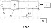
Figure 1 shows a diagram of one embodiment of the system shown in the present invention. -
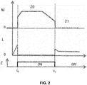
Figure 2 shows comparative electrical current plots flowing in the first reactive component (L) and the switching device (M), as well as the operation graph of the controller (10). - In various applications connected to electric power systems, the electric engine has a variation in its consumption current, that is, said engine uses an operation current and, at a certain moment, it needs more power, impacting in an increase of current. This increase is momentary and usually has a short duration.
- The present invention provides a system for correction of current harmonic content in power systems which is characterized in that it comprises an inductor sized to operate in a duty cycle, being protected by a switching device (M), which allows the inductor to have smaller dimensions, weight, and cost over conventional inductors.
- One of the objects of the present invention is a system for correcting harmonic current content in an electric power circuit comprising a switching device (M) associated with a reactive element (L).
- In one embodiment, said system comprises:
- a. at least one grinding system;
- b. at least one first reactive component (L) for reducing the harmonic content;
- c. at least one second reactive component (Cp);
- d. at least one switching device (M) associated with the first reactive component (L);
- e. at least one controller associated with said switching device (M); and
- f. at least one converter for engine control.
- In one embodiment, said first reactive component is an inducer. In one embodiment, said switching device is a relay, a logic switch, a timer, a MOSFET, or a combination thereof. In one embodiment, said converter is a frequency inverter.
- In one embodiment, the control system rectifies the signal from the
power source 13, directs the rectified signal to the second reactive component (Cp) and forwards it to an inverter (11). Depending on a signal, which may be time, an electrical signal resulting from an increase in voltage or other signal related to the occurrence of a maximum load regime, the switching device (M) is actuated, so that the current does not pass through the inductor L). When the switching device (M) is deactivated, the current passes through the inductor (L). - Another object of the present invention is a system for controlling electric engines comprising a circuit for correcting harmonic current content provided with a switching device (M) associated with a reactive element (L).
- Another object of the present invention is a refrigeration compressor comprising an electric engine control system having a circuit for correcting current harmonic content including a switching device (M) associated with a reactive element (L).
- In one embodiment, the compressor is of variable capacity. In one embodiment, the compressor has an inductor (L) which does not receive current during the pull-down cycle (10) of the compressor due to the actuation of the switching device (M), providing, among other advantages, the operation of the rotary compressor at a maximum load higher than that obtained when an inductor associated with the switching device is not used.
- The system of the invention is applicable to various electric power systems, such as electric engines - including compressor engines for refrigeration.
- Electric engines used in refrigeration compressors, for example, are subjected to two cycles: the pull-down cycle (10) and the regimen cycle (11), or normal cycle of operation. The pull-
down cycle 10 consists in lowering the temperature of the refrigerator according to a desired temperature, which occurs at the time the refrigerator is first started, or when the refrigerator is switched off for a long time. Therefore, the pull-down cycle (10) does not occur during the operation of the refrigerator. However, such a cycle requires a high power and an intense electric current, which generally implies in the oversizing of the inductor for the harmonic content correction of current. - The following examples are presented for the sole purpose of facilitating understanding of the inventive concept of the present invention in some of its embodiments and should not be construed as limiting the scope of the invention.
- The present invention provides a harmonic content correction system in power electrical circuits comprising an inductor (L) as the reactive component. The core of said inductor is provided with reduced dimensions, however meeting the requirements of electric current in the normal load regime. In this embodiment, when the regime is full-load or pull-down (10), the maximum engine operating temperature also occurs. In this embodiment, the inductor (L) does not receive current due to the actuation of the switching device (M), which protects the inductor. With this, the inductor is sized for operation in the normal regime of a variable capacity compressor.
- Referring to
Figure 1 , it will be appreciated that in this embodiment of the invention, overloading and oversizing of the first reactive component (L) is avoided due to the combination of a grinding system (12); A first reactive component (L), a second reactive component (Cp), a switching device (M), a control system (10) and an inverter (11). - The grinding system (12) is interconnected to an alternating current source (13), which is the power grid itself. The grinding system 12 rectifies the alternating signal coming from the
source 13 by converting it to DC signals. A second reactive component (Cp) is associated with the grinding system (12) and the inverter (11), so that the second reactive component (Cp) acts as a frequency filter. - A first reactive component (L) is associated with the second reactive component (Cp) and the inverter (11). Such a reactive component (L) in one embodiment is an inducer. Thus, said inductor (L) is arranged to reduce the impact of the harmonic content, the current of the inverter (11) and the reactive component (Cp) in the electric network (13).
- In many applications, the electric engine exhibits a variation in its current of consumption, that is, said engine uses an operation current and, in rare moments, it needs more power, impacting on an increase of current, in which this increase is momentary and has a short duration. In order to avoid that said inductor (L) has a very high geometry, because it is sized to withstand this current increase, and that an overload thereof occurs, a switching device (M) is associated with said inductor (L), So that both are connected in parallel. A controller (10) is associated with said switching device (M).
- In one embodiment, said switching device (M) is a selected from: is a relay, a logic switch, a timer, a MOSFET, or a combination thereof.
- The controller (10) is configured to drive the switching device (M), which can be done in a number of ways. In one embodiment, the drive is given over a predetermined time, signaling a thermostat, energizing the system, engine torque, inverter power, or any signal associated with the start and/or end of the cycle of an electric engine or pull down (20) from a refrigerator. In one embodiment, the
controller 10 detects the start of the pull-down cycle 20 from reading the power of theinverter 11, since when the cooler enters the pull-down cycle 20, the same Needs more power. As a result, at the time thecontroller 10 detects that the power of theinverter 11 exceeds a predetermined value, it sends a control signal to the switching device M, to return through said switching device (M). That is, when the switching device (M) enters the circuit, the first reactive element (L) is deactivated, i.e., taken out of operation. - The drive control characteristic of the switching device (M) protects the inductor (L) and enables its sizing to operate in the system cycle (21), as the high currents of the pull-down cycle (20) pass through the Switching device (M). In this way, the inductor (L) is operated with a lower electric current, having a reduced size and, consequently, a lower manufacturing cost, due to the fact that the amount of material to produce said inductor (L) is reduced. In addition, the energy dissipation in the inductor is smaller, providing better energy efficiency to the assembly.
-
Figure 2 shows a graph for the comparison of the electric current in the switching device (M) and the first reactive component (L). It is known that when thecontroller 10 is actuated in the pull-down cycle 20 the current passes through the switching device M and not the first reactive component L. At the time the cooling system returns to theduty cycle 21, the switching device M is deactivated and the current flows back through the first reactive component L. - Also in the
figure 2 , thecontroller 10 graph shows that it sends an ON signal to the switching device M, and thereafter sends a "OFF" shut-off signal to the said switching device (M). Thecontroller 10 detects the moment when the power of theinverter 11 is below a predefined value so as to send the OFF signal. - The present invention also provides a method of controlling electric engines wherein it comprises dimensioning a first reactive element (L) for operation in a duty cycle (21). Thereby, the system is started and comprises the step of rectifying the signal from the mains (13) through a rectifying system (12), converting said signal to DC.
- The signal is then directed to a second reactive component (Cp), in which it is routed to an inverter (11). The
controller 10 detects the start of the pull-down cycle 20 of the cooler, and drives the switching device M, causing the current of the pull-down cycle 20 to travel through said switching device M). - In one embodiment, the start of the pull-down cycle (20) is associated with the power variation of the inverter (11), thus, at the time when the power value of the inverter (11) is greater than a value of the controller (10), it actuates the switching device (M), causing the current to travel therethrough.
- The controller detects the end of the pull-down cycle (20), and thus, sends a control signal to the switching device, disabling it. Thus, in the embodiment of the pull-
down cycle 20 associated with the power of theinverter 11, at the moment when the power of theinverter 11 is less than a predetermined value, thecontrol system 10, Disengages the switching device (M), causing the current to pass through the first reactive component (L). - In this way, the solution proposed in the present invention allows the first reactive component (L) to be sized to operate in the regime current (21), which is the normal operating current of an engine. The first reactive element (L) thus comprises a reduced size and a reduced manufacturing cost due to the fact that it requires less material to produce the same.
- In the present invention, the control system is of a reduced size and weight, respecting the conditions of operation of the compressor during the pull-down cycle (10) of, for example, a refrigerator, to which the variable capacity compressor is installed. Among other advantages deriving from the use of this inductor for a compressor of variable capacity, the increase of the capacity (rotation) of the compressor at maximum load deserves to be highlighted, since the inductor has a low inductance and the impact on the available voltage drop for the compressor becomes smaller. The invention provides detectable decrease of the inductance during the maximum load operating regime. The maximum load rotation is greater than that obtained when the system of the invention is not used.
- Those skilled in the art will appreciate the knowledge presented herein and may reproduce the invention in the embodiments presented and in other embodiments, falling within the scope of the appended claims..
Claims (12)
- System for correcting harmonic current content in an electric power circuit characterized in that it comprises a switching device (M) associated with a reactive element (L).
- System according to Claim 1, characterized in that it comprises:a. at least one grinding system;b. at least one first reactive component (L) for reducing the harmonic content;c. at least one second reactive component (Cp);d. at least one switching device (M) associated with the first reactive component (L);e. at least one controller associated with said switching device (M); andf. at least one converter for engine control.
- System according to claim 2 characterized in that said first reactive component is an inducer.
- System according to claim 2 or 3, characterized in that said switching device is a relay, a logic switch, a timer, a MOSFET, or a combination thereof.
- System according to claim 2, 3 or 4 characterized in that said converter is a frequency inverter (11).
- System according to any one of the preceding claims, characterized in that the control system:- rectifies the signal from the power source (13), directs the rectified signal to the second reactive component (Cp) and forwards it to an inverter (11);- a signal activates the switching device (M), causing the current to not pass through the inductor (L);- a signal disengages the switching device (M), causing the current to pass through the inductor (L).
- System according to any one of the preceding claims, characterized in that the switch-on and/or switch-off signal of the switching device (M) is selected from: over a predetermined time; Signaling a thermostat; Energizing the system; Engine torque; Power inverter; a signal associated with the start and/or end of the maximum charge cycle of an electric engine or pull down (20) of a refrigerator.
- System for controlling electric engines characterized in that it comprises a circuit for correcting current harmonic content as defined in claims 1-7.
- Refrigeration compressor, characterized in that it comprises the electric engine control system defined in claim 8.
- Compressor according to claim 9, characterized in that it is a variable capacity compressor.
- Compressor according to claim 9 or 10 characterized in that the inductor (L) does not receive current during the pull-down cycle (10) of the compressor.
- Compressor according to any one of claims 9-11 characterized in that the maximum load rotation is greater than that obtained when the inductor system (L) associated with a switching device (M) is not used.
Applications Claiming Priority (1)
| Application Number | Priority Date | Filing Date | Title |
|---|---|---|---|
| BR102015030840-0A BR102015030840B1 (en) | 2015-12-09 | 2015-12-09 | System for harmonic content reduction in electric power circuit and compressor for refrigeration |
Publications (3)
| Publication Number | Publication Date |
|---|---|
| EP3179618A2 true EP3179618A2 (en) | 2017-06-14 |
| EP3179618A3 EP3179618A3 (en) | 2017-07-12 |
| EP3179618B1 EP3179618B1 (en) | 2020-07-01 |
Family
ID=57749646
Family Applications (1)
| Application Number | Title | Priority Date | Filing Date |
|---|---|---|---|
| EP16202746.0A Active EP3179618B1 (en) | 2015-12-09 | 2016-12-07 | System for harmonic content correction in power electric circuit |
Country Status (6)
| Country | Link |
|---|---|
| US (1) | US10148165B2 (en) |
| EP (1) | EP3179618B1 (en) |
| JP (1) | JP2017108621A (en) |
| CN (1) | CN106856367B (en) |
| BR (1) | BR102015030840B1 (en) |
| ES (1) | ES2817058T3 (en) |
Family Cites Families (13)
| Publication number | Priority date | Publication date | Assignee | Title |
|---|---|---|---|---|
| US4805082A (en) * | 1988-03-14 | 1989-02-14 | Westinghouse Electric Corp. | Regenerative two-quadrant converter |
| KR960016605B1 (en) * | 1992-11-20 | 1996-12-16 | 마쯔시다 덴꼬 가부시끼가이샤 | Power supply |
| CN1240063A (en) * | 1996-12-10 | 1999-12-29 | 松下冷机株式会社 | Power unit |
| US5994869A (en) * | 1997-12-05 | 1999-11-30 | General Electric Company | Power conversion circuit for a motor |
| JP2007325388A (en) * | 2006-05-31 | 2007-12-13 | Hitachi Ltd | Electric motor control device and in-vehicle electric motor drive system |
| US8179701B2 (en) * | 2009-01-09 | 2012-05-15 | Yaskawa America, Inc. | Variable frequency drive soft charge circuit |
| JP2010187521A (en) * | 2009-01-16 | 2010-08-26 | Mitsubishi Electric Corp | Motor drive controller, compressor, blower, air conditioner and refrigerator or freezer |
| JP5460727B2 (en) * | 2009-10-16 | 2014-04-02 | 三菱電機株式会社 | Vehicle power supply system |
| US8891254B2 (en) * | 2012-06-01 | 2014-11-18 | Panasonic Corporation | Power converter and battery charger using the same |
| JP5850069B2 (en) * | 2012-09-28 | 2016-02-03 | ダイキン工業株式会社 | Power consumption reduction device |
| JP5713978B2 (en) * | 2012-10-05 | 2015-05-07 | 三菱電機株式会社 | DC power supply device, motor drive device, air conditioner, refrigerator and heat pump water heater |
| EP2784931B1 (en) * | 2013-03-25 | 2022-06-08 | ebm-papst Mulfingen GmbH & Co. KG | Method and control circuit for controlling a brushless electric motor |
| WO2014192084A1 (en) * | 2013-05-28 | 2014-12-04 | 三菱電機株式会社 | Power convertor, motor drive control device equipped with power convertor, compressor and blower equipped with motor drive control device, and air conditioner equipped with compressor or blower |
-
2015
- 2015-12-09 BR BR102015030840-0A patent/BR102015030840B1/en active IP Right Grant
-
2016
- 2016-12-07 US US15/371,749 patent/US10148165B2/en active Active
- 2016-12-07 ES ES16202746T patent/ES2817058T3/en active Active
- 2016-12-07 EP EP16202746.0A patent/EP3179618B1/en active Active
- 2016-12-08 JP JP2016238403A patent/JP2017108621A/en active Pending
- 2016-12-09 CN CN201611271675.5A patent/CN106856367B/en active Active
Non-Patent Citations (1)
| Title |
|---|
| None |
Also Published As
| Publication number | Publication date |
|---|---|
| CN106856367A (en) | 2017-06-16 |
| JP2017108621A (en) | 2017-06-15 |
| ES2817058T3 (en) | 2021-04-06 |
| EP3179618A3 (en) | 2017-07-12 |
| BR102015030840B1 (en) | 2022-04-19 |
| US20170194852A1 (en) | 2017-07-06 |
| BR102015030840A2 (en) | 2017-06-13 |
| BR102015030840A8 (en) | 2022-02-08 |
| US10148165B2 (en) | 2018-12-04 |
| EP3179618B1 (en) | 2020-07-01 |
| CN106856367B (en) | 2021-06-11 |
Similar Documents
| Publication | Publication Date | Title |
|---|---|---|
| US7957166B2 (en) | Variable speed drive | |
| US8174853B2 (en) | Variable speed drive | |
| US20100091417A1 (en) | Overvoltage protective device for wind energy installations | |
| JP4350160B1 (en) | Magnetic energy regenerative switch with protection circuit | |
| JP6072937B2 (en) | DC power supply device and refrigeration cycle application equipment including the same | |
| US20180091057A1 (en) | Inrush current limiting method based on buck+boost topology | |
| JP2013009475A (en) | Surge current suppression circuit | |
| JP6648577B2 (en) | Power converter | |
| Gardell et al. | Adjustable-speed drive motor protection applications and issues | |
| KR20150139559A (en) | Current-limiting device | |
| KR20090086141A (en) | Zigzag connection transformer type image harmonic reduction device with current limiting protection function by FITISH element | |
| US10148165B2 (en) | System for harmonic content correction in power electric circuit, system for electric engine control, and cooling compressor | |
| CN111049410B (en) | Control method of electric energy conversion device and electric energy conversion system | |
| CA3074253C (en) | Wind turbine with power-dependent filter device | |
| Huffman | Introduction to solid-state adjustable speed drives | |
| Jeong et al. | Design of 35 kJ/s 25 kV capacitor charging power supply for pulsed power systems | |
| US20170257021A1 (en) | System for Correction of Harmonic Content in Electric Power Circuit, System for Control of Electric Motors, and Refrigeration Compressor | |
| Raspotnig | Power supplies with significantly reduced inrush current | |
| Li et al. | A Cost-Effective DC Breaker With Robust Breaking and Minimized Pulse Current | |
| JP2004343832A (en) | Micro surge voltage suppression circuit | |
| US20250385624A1 (en) | Power conditioning system for reduced-voltage soft starters configured to operate with long shielded load cables | |
| KR20110035117A (en) | Single phase induction motor control device and method | |
| GB2533965A (en) | Improved AC supply voltage, current and power factor regulator | |
| EP3438543B1 (en) | Surge suppression circuit and microwave oven | |
| LeDoux et al. | New technology assists the design of outdoor rated medium voltage drives |
Legal Events
| Date | Code | Title | Description |
|---|---|---|---|
| PUAI | Public reference made under article 153(3) epc to a published international application that has entered the european phase |
Free format text: ORIGINAL CODE: 0009012 |
|
| STAA | Information on the status of an ep patent application or granted ep patent |
Free format text: STATUS: THE APPLICATION HAS BEEN PUBLISHED |
|
| AK | Designated contracting states |
Kind code of ref document: A2 Designated state(s): AL AT BE BG CH CY CZ DE DK EE ES FI FR GB GR HR HU IE IS IT LI LT LU LV MC MK MT NL NO PL PT RO RS SE SI SK SM TR |
|
| AX | Request for extension of the european patent |
Extension state: BA ME |
|
| PUAL | Search report despatched |
Free format text: ORIGINAL CODE: 0009013 |
|
| AK | Designated contracting states |
Kind code of ref document: A3 Designated state(s): AL AT BE BG CH CY CZ DE DK EE ES FI FR GB GR HR HU IE IS IT LI LT LU LV MC MK MT NL NO PL PT RO RS SE SI SK SM TR |
|
| AX | Request for extension of the european patent |
Extension state: BA ME |
|
| RIC1 | Information provided on ipc code assigned before grant |
Ipc: H02M 1/32 20070101ALN20170608BHEP Ipc: H02M 1/12 20060101AFI20170608BHEP |
|
| STAA | Information on the status of an ep patent application or granted ep patent |
Free format text: STATUS: REQUEST FOR EXAMINATION WAS MADE |
|
| 17P | Request for examination filed |
Effective date: 20180110 |
|
| RBV | Designated contracting states (corrected) |
Designated state(s): AL AT BE BG CH CY CZ DE DK EE ES FI FR GB GR HR HU IE IS IT LI LT LU LV MC MK MT NL NO PL PT RO RS SE SI SK SM TR |
|
| STAA | Information on the status of an ep patent application or granted ep patent |
Free format text: STATUS: EXAMINATION IS IN PROGRESS |
|
| 17Q | First examination report despatched |
Effective date: 20180713 |
|
| RAP1 | Party data changed (applicant data changed or rights of an application transferred) |
Owner name: EMBRACO INDUSTRIA DE COMPRESSORES E SOLUCOES EM RE |
|
| GRAP | Despatch of communication of intention to grant a patent |
Free format text: ORIGINAL CODE: EPIDOSNIGR1 |
|
| STAA | Information on the status of an ep patent application or granted ep patent |
Free format text: STATUS: GRANT OF PATENT IS INTENDED |
|
| RIC1 | Information provided on ipc code assigned before grant |
Ipc: H02M 1/32 20070101ALN20191211BHEP Ipc: H02M 1/12 20060101AFI20191211BHEP |
|
| INTG | Intention to grant announced |
Effective date: 20200107 |
|
| GRAS | Grant fee paid |
Free format text: ORIGINAL CODE: EPIDOSNIGR3 |
|
| GRAA | (expected) grant |
Free format text: ORIGINAL CODE: 0009210 |
|
| STAA | Information on the status of an ep patent application or granted ep patent |
Free format text: STATUS: THE PATENT HAS BEEN GRANTED |
|
| AK | Designated contracting states |
Kind code of ref document: B1 Designated state(s): AL AT BE BG CH CY CZ DE DK EE ES FI FR GB GR HR HU IE IS IT LI LT LU LV MC MK MT NL NO PL PT RO RS SE SI SK SM TR |
|
| REG | Reference to a national code |
Ref country code: AT Ref legal event code: REF Ref document number: 1287112 Country of ref document: AT Kind code of ref document: T Effective date: 20200715 Ref country code: CH Ref legal event code: EP |
|
| REG | Reference to a national code |
Ref country code: IE Ref legal event code: FG4D |
|
| REG | Reference to a national code |
Ref country code: DE Ref legal event code: R096 Ref document number: 602016039031 Country of ref document: DE |
|
| REG | Reference to a national code |
Ref country code: LT Ref legal event code: MG4D |
|
| PG25 | Lapsed in a contracting state [announced via postgrant information from national office to epo] |
Ref country code: BG Free format text: LAPSE BECAUSE OF FAILURE TO SUBMIT A TRANSLATION OF THE DESCRIPTION OR TO PAY THE FEE WITHIN THE PRESCRIBED TIME-LIMIT Effective date: 20201001 |
|
| REG | Reference to a national code |
Ref country code: SK Ref legal event code: T3 Ref document number: E 35239 Country of ref document: SK |
|
| REG | Reference to a national code |
Ref country code: NL Ref legal event code: MP Effective date: 20200701 |
|
| PG25 | Lapsed in a contracting state [announced via postgrant information from national office to epo] |
Ref country code: GR Free format text: LAPSE BECAUSE OF FAILURE TO SUBMIT A TRANSLATION OF THE DESCRIPTION OR TO PAY THE FEE WITHIN THE PRESCRIBED TIME-LIMIT Effective date: 20201002 Ref country code: NO Free format text: LAPSE BECAUSE OF FAILURE TO SUBMIT A TRANSLATION OF THE DESCRIPTION OR TO PAY THE FEE WITHIN THE PRESCRIBED TIME-LIMIT Effective date: 20201001 Ref country code: CZ Free format text: LAPSE BECAUSE OF FAILURE TO SUBMIT A TRANSLATION OF THE DESCRIPTION OR TO PAY THE FEE WITHIN THE PRESCRIBED TIME-LIMIT Effective date: 20200701 Ref country code: HR Free format text: LAPSE BECAUSE OF FAILURE TO SUBMIT A TRANSLATION OF THE DESCRIPTION OR TO PAY THE FEE WITHIN THE PRESCRIBED TIME-LIMIT Effective date: 20200701 Ref country code: SE Free format text: LAPSE BECAUSE OF FAILURE TO SUBMIT A TRANSLATION OF THE DESCRIPTION OR TO PAY THE FEE WITHIN THE PRESCRIBED TIME-LIMIT Effective date: 20200701 Ref country code: FI Free format text: LAPSE BECAUSE OF FAILURE TO SUBMIT A TRANSLATION OF THE DESCRIPTION OR TO PAY THE FEE WITHIN THE PRESCRIBED TIME-LIMIT Effective date: 20200701 Ref country code: PT Free format text: LAPSE BECAUSE OF FAILURE TO SUBMIT A TRANSLATION OF THE DESCRIPTION OR TO PAY THE FEE WITHIN THE PRESCRIBED TIME-LIMIT Effective date: 20201102 Ref country code: LT Free format text: LAPSE BECAUSE OF FAILURE TO SUBMIT A TRANSLATION OF THE DESCRIPTION OR TO PAY THE FEE WITHIN THE PRESCRIBED TIME-LIMIT Effective date: 20200701 |
|
| PG25 | Lapsed in a contracting state [announced via postgrant information from national office to epo] |
Ref country code: IS Free format text: LAPSE BECAUSE OF FAILURE TO SUBMIT A TRANSLATION OF THE DESCRIPTION OR TO PAY THE FEE WITHIN THE PRESCRIBED TIME-LIMIT Effective date: 20201101 Ref country code: LV Free format text: LAPSE BECAUSE OF FAILURE TO SUBMIT A TRANSLATION OF THE DESCRIPTION OR TO PAY THE FEE WITHIN THE PRESCRIBED TIME-LIMIT Effective date: 20200701 Ref country code: PL Free format text: LAPSE BECAUSE OF FAILURE TO SUBMIT A TRANSLATION OF THE DESCRIPTION OR TO PAY THE FEE WITHIN THE PRESCRIBED TIME-LIMIT Effective date: 20200701 Ref country code: RS Free format text: LAPSE BECAUSE OF FAILURE TO SUBMIT A TRANSLATION OF THE DESCRIPTION OR TO PAY THE FEE WITHIN THE PRESCRIBED TIME-LIMIT Effective date: 20200701 |
|
| REG | Reference to a national code |
Ref country code: AT Ref legal event code: UEP Ref document number: 1287112 Country of ref document: AT Kind code of ref document: T Effective date: 20200701 |
|
| PG25 | Lapsed in a contracting state [announced via postgrant information from national office to epo] |
Ref country code: NL Free format text: LAPSE BECAUSE OF FAILURE TO SUBMIT A TRANSLATION OF THE DESCRIPTION OR TO PAY THE FEE WITHIN THE PRESCRIBED TIME-LIMIT Effective date: 20200701 |
|
| REG | Reference to a national code |
Ref country code: DE Ref legal event code: R097 Ref document number: 602016039031 Country of ref document: DE Ref country code: ES Ref legal event code: FG2A Ref document number: 2817058 Country of ref document: ES Kind code of ref document: T3 Effective date: 20210406 |
|
| PG25 | Lapsed in a contracting state [announced via postgrant information from national office to epo] |
Ref country code: EE Free format text: LAPSE BECAUSE OF FAILURE TO SUBMIT A TRANSLATION OF THE DESCRIPTION OR TO PAY THE FEE WITHIN THE PRESCRIBED TIME-LIMIT Effective date: 20200701 Ref country code: SM Free format text: LAPSE BECAUSE OF FAILURE TO SUBMIT A TRANSLATION OF THE DESCRIPTION OR TO PAY THE FEE WITHIN THE PRESCRIBED TIME-LIMIT Effective date: 20200701 Ref country code: RO Free format text: LAPSE BECAUSE OF FAILURE TO SUBMIT A TRANSLATION OF THE DESCRIPTION OR TO PAY THE FEE WITHIN THE PRESCRIBED TIME-LIMIT Effective date: 20200701 Ref country code: DK Free format text: LAPSE BECAUSE OF FAILURE TO SUBMIT A TRANSLATION OF THE DESCRIPTION OR TO PAY THE FEE WITHIN THE PRESCRIBED TIME-LIMIT Effective date: 20200701 |
|
| PLBE | No opposition filed within time limit |
Free format text: ORIGINAL CODE: 0009261 |
|
| STAA | Information on the status of an ep patent application or granted ep patent |
Free format text: STATUS: NO OPPOSITION FILED WITHIN TIME LIMIT |
|
| PG25 | Lapsed in a contracting state [announced via postgrant information from national office to epo] |
Ref country code: AL Free format text: LAPSE BECAUSE OF FAILURE TO SUBMIT A TRANSLATION OF THE DESCRIPTION OR TO PAY THE FEE WITHIN THE PRESCRIBED TIME-LIMIT Effective date: 20200701 |
|
| 26N | No opposition filed |
Effective date: 20210406 |
|
| REG | Reference to a national code |
Ref country code: CH Ref legal event code: PL |
|
| GBPC | Gb: european patent ceased through non-payment of renewal fee |
Effective date: 20201207 |
|
| PG25 | Lapsed in a contracting state [announced via postgrant information from national office to epo] |
Ref country code: MC Free format text: LAPSE BECAUSE OF FAILURE TO SUBMIT A TRANSLATION OF THE DESCRIPTION OR TO PAY THE FEE WITHIN THE PRESCRIBED TIME-LIMIT Effective date: 20200701 Ref country code: SI Free format text: LAPSE BECAUSE OF FAILURE TO SUBMIT A TRANSLATION OF THE DESCRIPTION OR TO PAY THE FEE WITHIN THE PRESCRIBED TIME-LIMIT Effective date: 20200701 |
|
| REG | Reference to a national code |
Ref country code: BE Ref legal event code: MM Effective date: 20201231 |
|
| PG25 | Lapsed in a contracting state [announced via postgrant information from national office to epo] |
Ref country code: IE Free format text: LAPSE BECAUSE OF NON-PAYMENT OF DUE FEES Effective date: 20201207 Ref country code: FR Free format text: LAPSE BECAUSE OF NON-PAYMENT OF DUE FEES Effective date: 20201231 Ref country code: LU Free format text: LAPSE BECAUSE OF NON-PAYMENT OF DUE FEES Effective date: 20201207 |
|
| PG25 | Lapsed in a contracting state [announced via postgrant information from national office to epo] |
Ref country code: GB Free format text: LAPSE BECAUSE OF NON-PAYMENT OF DUE FEES Effective date: 20201207 Ref country code: LI Free format text: LAPSE BECAUSE OF NON-PAYMENT OF DUE FEES Effective date: 20201231 Ref country code: CH Free format text: LAPSE BECAUSE OF NON-PAYMENT OF DUE FEES Effective date: 20201231 |
|
| PG25 | Lapsed in a contracting state [announced via postgrant information from national office to epo] |
Ref country code: IS Free format text: LAPSE BECAUSE OF FAILURE TO SUBMIT A TRANSLATION OF THE DESCRIPTION OR TO PAY THE FEE WITHIN THE PRESCRIBED TIME-LIMIT Effective date: 20201101 Ref country code: MT Free format text: LAPSE BECAUSE OF FAILURE TO SUBMIT A TRANSLATION OF THE DESCRIPTION OR TO PAY THE FEE WITHIN THE PRESCRIBED TIME-LIMIT Effective date: 20200701 Ref country code: CY Free format text: LAPSE BECAUSE OF FAILURE TO SUBMIT A TRANSLATION OF THE DESCRIPTION OR TO PAY THE FEE WITHIN THE PRESCRIBED TIME-LIMIT Effective date: 20200701 |
|
| PG25 | Lapsed in a contracting state [announced via postgrant information from national office to epo] |
Ref country code: MK Free format text: LAPSE BECAUSE OF FAILURE TO SUBMIT A TRANSLATION OF THE DESCRIPTION OR TO PAY THE FEE WITHIN THE PRESCRIBED TIME-LIMIT Effective date: 20200701 |
|
| PG25 | Lapsed in a contracting state [announced via postgrant information from national office to epo] |
Ref country code: BE Free format text: LAPSE BECAUSE OF NON-PAYMENT OF DUE FEES Effective date: 20201231 |
|
| PGFP | Annual fee paid to national office [announced via postgrant information from national office to epo] |
Ref country code: AT Payment date: 20221222 Year of fee payment: 7 |
|
| PGFP | Annual fee paid to national office [announced via postgrant information from national office to epo] |
Ref country code: ES Payment date: 20230228 Year of fee payment: 7 |
|
| PGFP | Annual fee paid to national office [announced via postgrant information from national office to epo] |
Ref country code: IT Payment date: 20221228 Year of fee payment: 7 |
|
| REG | Reference to a national code |
Ref country code: AT Ref legal event code: MM01 Ref document number: 1287112 Country of ref document: AT Kind code of ref document: T Effective date: 20231207 |
|
| PG25 | Lapsed in a contracting state [announced via postgrant information from national office to epo] |
Ref country code: AT Free format text: LAPSE BECAUSE OF NON-PAYMENT OF DUE FEES Effective date: 20231207 |
|
| PG25 | Lapsed in a contracting state [announced via postgrant information from national office to epo] |
Ref country code: AT Free format text: LAPSE BECAUSE OF NON-PAYMENT OF DUE FEES Effective date: 20231207 |
|
| REG | Reference to a national code |
Ref country code: ES Ref legal event code: FD2A Effective date: 20250127 |
|
| PG25 | Lapsed in a contracting state [announced via postgrant information from national office to epo] |
Ref country code: ES Free format text: LAPSE BECAUSE OF NON-PAYMENT OF DUE FEES Effective date: 20231208 |
|
| PG25 | Lapsed in a contracting state [announced via postgrant information from national office to epo] |
Ref country code: IT Free format text: LAPSE BECAUSE OF NON-PAYMENT OF DUE FEES Effective date: 20231207 |
|
| PGFP | Annual fee paid to national office [announced via postgrant information from national office to epo] |
Ref country code: TR Payment date: 20251106 Year of fee payment: 10 |
|
| PGFP | Annual fee paid to national office [announced via postgrant information from national office to epo] |
Ref country code: SK Payment date: 20251126 Year of fee payment: 10 |
|
| PGFP | Annual fee paid to national office [announced via postgrant information from national office to epo] |
Ref country code: DE Payment date: 20251231 Year of fee payment: 10 |