EP3179585A1 - Raceway - Google Patents
Raceway Download PDFInfo
- Publication number
- EP3179585A1 EP3179585A1 EP16199532.9A EP16199532A EP3179585A1 EP 3179585 A1 EP3179585 A1 EP 3179585A1 EP 16199532 A EP16199532 A EP 16199532A EP 3179585 A1 EP3179585 A1 EP 3179585A1
- Authority
- EP
- European Patent Office
- Prior art keywords
- raceway
- intumescent
- channel
- intumescent layer
- open side
- Prior art date
- Legal status (The legal status is an assumption and is not a legal conclusion. Google has not performed a legal analysis and makes no representation as to the accuracy of the status listed.)
- Granted
Links
Images



Classifications
-
- H—ELECTRICITY
- H02—GENERATION; CONVERSION OR DISTRIBUTION OF ELECTRIC POWER
- H02G—INSTALLATION OF ELECTRIC CABLES OR LINES, OR OF COMBINED OPTICAL AND ELECTRIC CABLES OR LINES
- H02G3/00—Installations of electric cables or lines or protective tubing therefor in or on buildings, equivalent structures or vehicles
- H02G3/02—Details
- H02G3/04—Protective tubing or conduits, e.g. cable ladders or cable troughs
-
- F—MECHANICAL ENGINEERING; LIGHTING; HEATING; WEAPONS; BLASTING
- F16—ENGINEERING ELEMENTS AND UNITS; GENERAL MEASURES FOR PRODUCING AND MAINTAINING EFFECTIVE FUNCTIONING OF MACHINES OR INSTALLATIONS; THERMAL INSULATION IN GENERAL
- F16L—PIPES; JOINTS OR FITTINGS FOR PIPES; SUPPORTS FOR PIPES, CABLES OR PROTECTIVE TUBING; MEANS FOR THERMAL INSULATION IN GENERAL
- F16L3/00—Supports for pipes, cables or protective tubing, e.g. hangers, holders, clamps, cleats, clips, brackets
- F16L3/26—Supports for pipes, cables or protective tubing, e.g. hangers, holders, clamps, cleats, clips, brackets specially adapted for supporting the pipes all along their length, e.g. pipe channels or ducts
-
- H—ELECTRICITY
- H02—GENERATION; CONVERSION OR DISTRIBUTION OF ELECTRIC POWER
- H02G—INSTALLATION OF ELECTRIC CABLES OR LINES, OR OF COMBINED OPTICAL AND ELECTRIC CABLES OR LINES
- H02G3/00—Installations of electric cables or lines or protective tubing therefor in or on buildings, equivalent structures or vehicles
- H02G3/02—Details
- H02G3/04—Protective tubing or conduits, e.g. cable ladders or cable troughs
- H02G3/0406—Details thereof
- H02G3/0412—Heat or fire protective means
-
- F—MECHANICAL ENGINEERING; LIGHTING; HEATING; WEAPONS; BLASTING
- F16—ENGINEERING ELEMENTS AND UNITS; GENERAL MEASURES FOR PRODUCING AND MAINTAINING EFFECTIVE FUNCTIONING OF MACHINES OR INSTALLATIONS; THERMAL INSULATION IN GENERAL
- F16L—PIPES; JOINTS OR FITTINGS FOR PIPES; SUPPORTS FOR PIPES, CABLES OR PROTECTIVE TUBING; MEANS FOR THERMAL INSULATION IN GENERAL
- F16L3/00—Supports for pipes, cables or protective tubing, e.g. hangers, holders, clamps, cleats, clips, brackets
-
- F—MECHANICAL ENGINEERING; LIGHTING; HEATING; WEAPONS; BLASTING
- F16—ENGINEERING ELEMENTS AND UNITS; GENERAL MEASURES FOR PRODUCING AND MAINTAINING EFFECTIVE FUNCTIONING OF MACHINES OR INSTALLATIONS; THERMAL INSULATION IN GENERAL
- F16L—PIPES; JOINTS OR FITTINGS FOR PIPES; SUPPORTS FOR PIPES, CABLES OR PROTECTIVE TUBING; MEANS FOR THERMAL INSULATION IN GENERAL
- F16L3/00—Supports for pipes, cables or protective tubing, e.g. hangers, holders, clamps, cleats, clips, brackets
- F16L3/22—Supports for pipes, cables or protective tubing, e.g. hangers, holders, clamps, cleats, clips, brackets specially adapted for supporting a number of parallel pipes at intervals
- F16L3/223—Supports for pipes, cables or protective tubing, e.g. hangers, holders, clamps, cleats, clips, brackets specially adapted for supporting a number of parallel pipes at intervals each support having one transverse base for supporting the pipes
-
- F—MECHANICAL ENGINEERING; LIGHTING; HEATING; WEAPONS; BLASTING
- F16—ENGINEERING ELEMENTS AND UNITS; GENERAL MEASURES FOR PRODUCING AND MAINTAINING EFFECTIVE FUNCTIONING OF MACHINES OR INSTALLATIONS; THERMAL INSULATION IN GENERAL
- F16L—PIPES; JOINTS OR FITTINGS FOR PIPES; SUPPORTS FOR PIPES, CABLES OR PROTECTIVE TUBING; MEANS FOR THERMAL INSULATION IN GENERAL
- F16L3/00—Supports for pipes, cables or protective tubing, e.g. hangers, holders, clamps, cleats, clips, brackets
- F16L3/22—Supports for pipes, cables or protective tubing, e.g. hangers, holders, clamps, cleats, clips, brackets specially adapted for supporting a number of parallel pipes at intervals
- F16L3/23—Supports for pipes, cables or protective tubing, e.g. hangers, holders, clamps, cleats, clips, brackets specially adapted for supporting a number of parallel pipes at intervals for a bundle of pipes or a plurality of pipes placed side by side in contact with each other
-
- F—MECHANICAL ENGINEERING; LIGHTING; HEATING; WEAPONS; BLASTING
- F16—ENGINEERING ELEMENTS AND UNITS; GENERAL MEASURES FOR PRODUCING AND MAINTAINING EFFECTIVE FUNCTIONING OF MACHINES OR INSTALLATIONS; THERMAL INSULATION IN GENERAL
- F16L—PIPES; JOINTS OR FITTINGS FOR PIPES; SUPPORTS FOR PIPES, CABLES OR PROTECTIVE TUBING; MEANS FOR THERMAL INSULATION IN GENERAL
- F16L59/00—Thermal insulation in general
- F16L59/14—Arrangements for the insulation of pipes or pipe systems
-
- H—ELECTRICITY
- H02—GENERATION; CONVERSION OR DISTRIBUTION OF ELECTRIC POWER
- H02G—INSTALLATION OF ELECTRIC CABLES OR LINES, OR OF COMBINED OPTICAL AND ELECTRIC CABLES OR LINES
- H02G3/00—Installations of electric cables or lines or protective tubing therefor in or on buildings, equivalent structures or vehicles
- H02G3/02—Details
- H02G3/04—Protective tubing or conduits, e.g. cable ladders or cable troughs
- H02G3/0406—Details thereof
-
- H—ELECTRICITY
- H02—GENERATION; CONVERSION OR DISTRIBUTION OF ELECTRIC POWER
- H02G—INSTALLATION OF ELECTRIC CABLES OR LINES, OR OF COMBINED OPTICAL AND ELECTRIC CABLES OR LINES
- H02G3/00—Installations of electric cables or lines or protective tubing therefor in or on buildings, equivalent structures or vehicles
- H02G3/02—Details
- H02G3/04—Protective tubing or conduits, e.g. cable ladders or cable troughs
- H02G3/0437—Channels
-
- B—PERFORMING OPERATIONS; TRANSPORTING
- B64—AIRCRAFT; AVIATION; COSMONAUTICS
- B64D—EQUIPMENT FOR FITTING IN OR TO AIRCRAFT; FLIGHT SUITS; PARACHUTES; ARRANGEMENT OR MOUNTING OF POWER PLANTS OR PROPULSION TRANSMISSIONS IN AIRCRAFT
- B64D2221/00—Electric power distribution systems onboard aircraft
Definitions
- raceways may be used for supporting power or signal conductors such as pipes, cables or wires with resect to a structure.
- Raceways are generally arranged to be fixed to a support structure and to provide one or more channels for holding power or data carriers such as pipes, cables or wires.
- the power or data carriers may be tied or otherwise bound together in bundles before being housed in the raceway and may also be fixed within the raceway.
- the raceway supports the power and data carriers with respect to the support structure and may also provide some further physical protection or shielding of the supported power and data carriers.
- Embodiments of the present technology provide a raceway comprising: a plurality of wall portions adjoining a base portion together defining a plurality of longitudinal open channels, the open side of each channel being arranged to provide access for installation of one or more cables or pipes or wires within the respective channel; and an intumescent layer disposed on the inner surface of at least one of the wall portions adjacent the open side of the respective channel, the intumescent layer having a non-activated state in which the open side of the channel is maintained substantially open and a thermally activated state in which the or each intumescent layer expands so as to close the open side of the respective channel.
- the or each intumescent layer may be arranged to expand so as to substantially close the open side of the respective channel.
- the or each intumescent layer may be arranged to expand so as to at least partially close the open side of the respective channel.
- the or each intumescent layer is confined to the distal part of the inner surface of the wall portion relative to the base portion.
- a third intumescent layer may be disposed on substantially all the exterior longitudinal surfaces of the raceway. Intumescent layers may be disposed on either side of a given wall portion, the intumescent layers are contiguous so as to extend over the distal edge of the wall portion. At least two of the channels may be of substantially different volumes.
- the raceway may further comprising: one or more cable clip connector elements formed in the base portion within at least one of the channels; and a second intumescent layer disposed on the exterior longitudinal surface of the base portion adjacent the cable clip connector elements.
- the raceway according may be formed from aluminium or an aluminium alloy.
- An aircraft structure may comprise the raceway.
- Another embodiment provides a raceway comprising one or more channels for supporting power or signal conductors, the or each channel being at least partially coated with an intumescent material arranged to substantially close the or each channel in response to thermal activation of the intumescent material so as to thermally insulate the interior of the channel.
- a further embodiment provides a method of forming a raceway comprising the steps of: forming a plurality of wall portions adjoining a base portion together defining a plurality of longitudinal open channels, the open side of each channel being arranged to provide access for installation of one or more cables or pipes or wires within the respective channel; and disposing an intumescent layer on the inner surface of at least one of the wall portions adjacent the open side of the respective channel, the intumescent layer having a non-activated state in which the open side of the channel is maintained substantially open and a thermally activated state in which the or each intumescent layer expands so as to close the open side of the channel.
- the or each intumescent layer may be confined to the distal part of the inner surface of the wall portion relative to the base portion.
- a third intumescent layer may be disposed on substantially all the exterior longitudinal surfaces of the raceway. Intumescent layers may be disposed on either side of a given wall portion, the intumescent layers being contiguous so as to extend over the distal edge of the wall portion.
- Another embodiment provides a raceway substantially as disclosed herein with reference to figure 2 , figure 4a or figure 5a .
- an aircraft 101 comprises a pair of wings 103 faired into a fuselage 105.
- the wings 103 each carry an engine 107.
- the aircraft further comprises horizontal stabilizers 109 and a vertical tail plane 111 each attached at the rear of the fuselage 105.
- Aircraft systems (not shown) are distributed throughout the aircraft 101 and interconnected by suitable physical power or data carriers such as pipes, cables and wires arranged to enable the transmission of power, in the form of electrical or hydraulic power, or data, in the form of electrical or optical control or data signals between respective aircraft systems or sub-systems.
- suitable physical power or data carriers such as pipes, cables and wires arranged to enable the transmission of power, in the form of electrical or hydraulic power, or data, in the form of electrical or optical control or data signals between respective aircraft systems or sub-systems.
- Such pipes, cables and wires are mounted within raceways 113 fixed to the aircraft structure.
- raceways 113 The general location of the raceways 113 is indicated in figure 1 by the dotted line running fore and aft within the fuselage 105 fixed to the fuselage floor beams (not shown), and span-wise within each wing 103 fixed to the front spar (not shown). As will be understood by those skilled in the art, raceways 113 may be provided at any suitable location in the aircraft 101 to support cables, pipes or wires on an aircraft structural element.
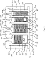
- the raceway 113 comprises a base portion 201 and five upstanding walls portions 203 which together with the base portion 201 define four longitudinal open channels 205a, 205b, 205c, 205d running along the length of the raceway 113 generally perpendicular to the cross section of figure 2 .
- an intumescent layer 207 in the form of an intumescent paint, is disposed on the outer surfaces of the base portion 201 and wall portions 203 of the raceway 113.
- the intumescent layer 207 further extends over the end surfaces of the outermost wall portions 203 distal to the base portion 201 and laps onto the respective inward facing surfaces of the outermost wall portions 203.
- the intumescent layer 207 thus extends into the respective outer channels 205a, 205d so as to be disposed on the distal parts of the inner surface of each respective outermost wall portion 203.
- further intumescent layers 209 are disposed on the respective distal ends of each of the three innermost wall portions 203.
- Each of the further intumescent layers 209 is disposed on the end surfaces of the innermost wall portions 203 and laps contiguously into the respective channel 205a, 205b, 205c, 205d onto the respective surfaces of each of the innermost wall portions 203.
- Each further intumescent layer 209 thus extends into the channels 205a, 205b, 205c, 205d so as to be disposed on the distal parts of the surface of each respective innermost wall portion 203 facing into the respective channel 205a, 205b, 205c, 205d.
- the portions of the intumescent layers 207, 209 disposed within the respective channels 205a, 205b, 205c, 205d are confined to the distal part of the surface of the respective wall portion 203 relative to the base portion.
- the intumescent layers 207, 209 extend over substantially all of the external surfaces of the raceway 113 and partway into each of the channels 205.
- Each of the channels 205a, 205b, 205c, 205d is provided with a further layer 211 covering the walls of the respective channel not otherwise covered by one of the intumescent layers 207, 209.
- the further layer is formed from nylon.
- Three of the channels 205a, 205b, 205c comprise cable clip connector elements 213 in the form of through-holes in the base portion 201, second intumescent layer 209 and further layer 211.
- the first cable bundle 215a is fixed together with a first cable clip 217 which itself is fixed to an insulating member 219 by a harpoon member 221 on the cable clip 217 engaged in a socket 223 defined in a face of the insulating member 219.
- the insulating member 219 sits in the base of the channel 215a between the base member 201 and the first cable bundle 215a and further comprises a harpoon member 225 engaged in the cable clip connector element 213 so to fix the cable bundle 215a within the channel 205a.
- the second cable bundle 215b is fixed together with a second cable clip 227 which comprises a harpoon member 229 engaged in the cable clip connector element 213 to fix the cable bundle 215b within the channel 205b.
- the third cable bundle 215c incorporates an insulating member 231 and is fixed together with a second cable clip 227.
- the insulating member 231 sits within the third cable bundle 215c, which is fixed within the channel 205c via the harpoon 229 engaged in the cable clip connector element 213.
- the fourth cable bundle 215d is fixed together with a third cable clip 233 and is fixed within the channel 205c by an interference fit between the bundle 215d and the sides of the channel 205d.
- each cable clip connector element 213 is arranged to provide an anchor point for the respective cable bundles 215a, 215b, 215c.
- the intumescent layers 207, 209 are made from an intumescent material having a non-activated state and an activated state.
- the intumescent layers 207, 209 are applied to the raceway 113 in the non-activated state.
- the intumescent layers 207, 209 are applied to the raceway 113 by painting.
- the intumescent material is arranged so as to move to the activated state in response to exposure to heat exceeding a predetermined temperature and exposure time threshold. In other words, the intumescent material is thermally activated. In its activated state, the intumescent material expands to form an insulating layer of material that is substantially heat resistant for a predetermined exposure time period.
- the intumescent layers 207, 209 are arranged in their activated state to insulate the raceway 113 from heat.
- the activated intumescent layers 207, 209 are arranged to insulate the cables in the cable bundles 215 from the effects of heat so that the cables maintain their operational integrity for a predetermined period.
- Figure 3 illustrates the intumescent layers 207, 209 in their activated state in which the raceway 113 is substantially enveloped in the insulative layer provided by the activated intumescent layers 207, 209.
- the intumescent layers 207, 209 in their activated state extend over substantially all of the external surfaces of the raceway 113 and partway into each of the channels 205. For the two rightmost channels 205c, 205d this results in the interior of these channels 205c, 205d containing the cable bundles 215c, 215d being substantially sealed from the exterior of the raceway 113 and the heat source by the expansion of the intumescent material across the longitudinal open side of the respective channel 205c, 205d.
- the interior of these channels 205a, 205b containing the cable bundles 215a, 215b being partially sealed from the exterior of the raceway 113 and the heat source by the expansion of the intumescent material part way across the longitudinal open side of the respective channel 205c, 205d.
- the partial sealing of the channels 205a, 205b is arranged to provide less insulation for the interior of the 205a, 205b than if the channels 205a, 205b were fully sealed but still to provide a required predetermined level of thermal insulation.
- the intumescent layer 207 also extends over the each cable clip connector element 213. As a result, in its activated state, the intumescent layer 207 insulates the respective harpoons 225 of the cable ties 217, 227 from the effects of heat. This insulative effect of the activates intumescent layer 207 is arranged to maintain the integrity of the cable clip 217, 227 so that the cable tie remains fixed within the raceway 113 in accordance with a predetermined temperature range and exposure time period.
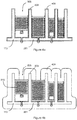
- a substantially contiguous intumescent layer 401 is disposed over all the longitudinal surfaces of the base and wall members 201, 203 of the raceway 113.
- the intumescent layer extends fully within each of the channels 205.
- the further layer 211 is omitted, as shown in figure 4a .
- Figure 4b illustrates the intumescent layer 401 in its activated state in which the raceway 113 is substantially enveloped in the insulative layer provided by the activated intumescent layer 401. Since the intumescent layer 401 extends over substantially all of the interior surfaces of each of the channels 205, the cable bundles 215 are both substantially sealed from the exterior of the raceway 113 and insulated from the interior surfaces of the base and wall portions 201, 203 of the raceway. 113. Thus the cable bundles are provided with two layers of insulation from the relevant heat source.
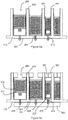
- the raceway 113 is provided with a set of discrete intumescent layers 501, 503.
- the first set of eight intumescent layers 501 are disposed on a respective distal portion of the surface of each wall portion 203 that faces into the respective channel 205.
- the second set of one intumescent layer 503 is disposed on at least part of the outer surfaces of the base portion 201 of the raceway 113 so as to extend over the or each cable clip connector element 213.
- Figure 5b illustrates the intumescent layers 501, 503 in their activated states in which the first set of eight intumescent layers 501 have together either partially or substantially closed the respective channels 205 as described above.
- the second intumescent layer 502 extends over the each cable clip connector element 213 and thus in its activated state insulates the respective harpoons 225, 229 of the cable ties 217, 227 from the effects of heat as described above.
- the raceway 113 in a first step, is integrally formed to comprise the base portion 201 and the five upstanding walls portions 203 which together with the base portion 201 define the four longitudinal open channels 205a, 205b, 205c, 205d running along the length of the raceway 113 generally perpendicular to the cross section of figure 6a .
- the raceway is integrally formed from aluminum by extrusion. The series of one or more through-holes are formed in the base portion 201 of three of the channels 205a, 205b, 205c to provide the cable clip connector elements 213.
- the intumescent layer 207 is applied to the outer surfaces of the base portion 201 and wall portions 203, the end surfaces of the outermost wall portions 203 distal to the base portion 201, and the respective inward facing surfaces of the outermost wall portions 203.
- the further intumescent layers 209 are applied to the respective distal ends of each of the three innermost wall portions 203, the end surfaces of the innermost wall portions 203, and the respective surfaces of each of the innermost wall portions 203.
- the further layers 211 are placed in each channel 205 covering the walls of the respective channel not otherwise covered by one of the intumescent layers 207, 209. Holes are formed in the further layers 211 corresponding to each cable clip connector element 213 where present in a given channel 205.
- the end faces of the raceway are provided with an intumescent layer which may be contiguous with one or more of the other intumescent layers disposed on the raceway.
- the function of the intumescent layer on the end face of the raceway is to partially or substantially close the end of each respective channel in conjunction with the closing of the longitudinal open side the respective channel as described above.
- one or more of the end faces of the raceway are generally free of intumescent material.
- the raceway may be integrally formed or constructed from a plurality of parts by any suitable forming means such as extrusion, milling, molding or any suitable constructing means such as welding, bonding or co-molding respectively.
- the raceway may be manufactured in strips including the intumescent layers and then cut or formed into shape for a given application.
- the raceway may be manufactured in strips, cut or formed into shape for a given application prior to the or each intumescent layers being applied.
- the or each intumescent layer may be disposed on the raceway by any suitable method such as painting, dipping, spraying, depositing or bonding.
Landscapes
- Engineering & Computer Science (AREA)
- General Engineering & Computer Science (AREA)
- Architecture (AREA)
- Civil Engineering (AREA)
- Structural Engineering (AREA)
- Mechanical Engineering (AREA)
- Details Of Indoor Wiring (AREA)
- Insulated Conductors (AREA)
Abstract
Description
- The present technology relates to raceways. Such raceways may be used for supporting power or signal conductors such as pipes, cables or wires with resect to a structure.
- Raceways are generally arranged to be fixed to a support structure and to provide one or more channels for holding power or data carriers such as pipes, cables or wires. The power or data carriers may be tied or otherwise bound together in bundles before being housed in the raceway and may also be fixed within the raceway. Thus the raceway supports the power and data carriers with respect to the support structure and may also provide some further physical protection or shielding of the supported power and data carriers.
- Embodiments of the present technology provide a raceway comprising: a plurality of wall portions adjoining a base portion together defining a plurality of longitudinal open channels, the open side of each channel being arranged to provide access for installation of one or more cables or pipes or wires within the respective channel; and an intumescent layer disposed on the inner surface of at least one of the wall portions adjacent the open side of the respective channel, the intumescent layer having a non-activated state in which the open side of the channel is maintained substantially open and a thermally activated state in which the or each intumescent layer expands so as to close the open side of the respective channel.
- Minimal or selected provision of the intumescent layers enables weight and costs of the raceway to be reduced.
- The or each intumescent layer may be arranged to expand so as to substantially close the open side of the respective channel. The or each intumescent layer may be arranged to expand so as to at least partially close the open side of the respective channel. The or each intumescent layer is confined to the distal part of the inner surface of the wall portion relative to the base portion. A third intumescent layer may be disposed on substantially all the exterior longitudinal surfaces of the raceway. Intumescent layers may be disposed on either side of a given wall portion, the intumescent layers are contiguous so as to extend over the distal edge of the wall portion. At least two of the channels may be of substantially different volumes. The raceway may further comprising: one or more cable clip connector elements formed in the base portion within at least one of the channels; and a second intumescent layer disposed on the exterior longitudinal surface of the base portion adjacent the cable clip connector elements. The raceway according may be formed from aluminium or an aluminium alloy. An aircraft structure may comprise the raceway.
- Another embodiment provides a raceway comprising one or more channels for supporting power or signal conductors, the or each channel being at least partially coated with an intumescent material arranged to substantially close the or each channel in response to thermal activation of the intumescent material so as to thermally insulate the interior of the channel.
- A further embodiment provides a method of forming a raceway comprising the steps of: forming a plurality of wall portions adjoining a base portion together defining a plurality of longitudinal open channels, the open side of each channel being arranged to provide access for installation of one or more cables or pipes or wires within the respective channel; and disposing an intumescent layer on the inner surface of at least one of the wall portions adjacent the open side of the respective channel, the intumescent layer having a non-activated state in which the open side of the channel is maintained substantially open and a thermally activated state in which the or each intumescent layer expands so as to close the open side of the channel.
- The or each intumescent layer may be confined to the distal part of the inner surface of the wall portion relative to the base portion. A third intumescent layer may be disposed on substantially all the exterior longitudinal surfaces of the raceway. Intumescent layers may be disposed on either side of a given wall portion, the intumescent layers being contiguous so as to extend over the distal edge of the wall portion.
- Another embodiment provides a raceway substantially as disclosed herein with reference to
figure 2 ,figure 4a orfigure 5a . - Embodiments of the technology will now be described, by way of example only, with reference to the following drawings in which:
-
Figure 1 is a perspective side view of an aircraft; -
Figure 2 is a cross-sectional view of a raceway in a non-activated state in the aircraft offigure 1 ; -
Figure 3 is a further cross-sectional view of the raceway offigure 2 in an activated state; -
Figures 4a & 4b are cross-sectional views of a raceway in respective non-activated and activated states in accordance with another embodiment of the technology; -
Figures 5a & 5b are cross-sectional views of a raceway in respective non-activated and activated states in accordance with a further embodiment of the technology; and -
Figures 6a, 6b & 6c are successive cross-sectional views illustrating manufacturing steps for the raceway offigure 2 . - With reference to
figure 1 , anaircraft 101 comprises a pair ofwings 103 faired into afuselage 105. Thewings 103 each carry anengine 107. The aircraft further compriseshorizontal stabilizers 109 and avertical tail plane 111 each attached at the rear of thefuselage 105. Aircraft systems (not shown) are distributed throughout theaircraft 101 and interconnected by suitable physical power or data carriers such as pipes, cables and wires arranged to enable the transmission of power, in the form of electrical or hydraulic power, or data, in the form of electrical or optical control or data signals between respective aircraft systems or sub-systems. Such pipes, cables and wires are mounted withinraceways 113 fixed to the aircraft structure. The general location of theraceways 113 is indicated infigure 1 by the dotted line running fore and aft within thefuselage 105 fixed to the fuselage floor beams (not shown), and span-wise within eachwing 103 fixed to the front spar (not shown). As will be understood by those skilled in the art,raceways 113 may be provided at any suitable location in theaircraft 101 to support cables, pipes or wires on an aircraft structural element. - With reference to
figure 2 , in one embodiment, theraceway 113 comprises abase portion 201 and fiveupstanding walls portions 203 which together with thebase portion 201 define four longitudinalopen channels raceway 113 generally perpendicular to the cross section offigure 2 . In the present embodiment, anintumescent layer 207, in the form of an intumescent paint, is disposed on the outer surfaces of thebase portion 201 andwall portions 203 of theraceway 113. Theintumescent layer 207 further extends over the end surfaces of theoutermost wall portions 203 distal to thebase portion 201 and laps onto the respective inward facing surfaces of theoutermost wall portions 203. Theintumescent layer 207 thus extends into the respectiveouter channels outermost wall portion 203. - In the present embodiment, further
intumescent layers 209 are disposed on the respective distal ends of each of the threeinnermost wall portions 203. Each of the furtherintumescent layers 209 is disposed on the end surfaces of theinnermost wall portions 203 and laps contiguously into therespective channel innermost wall portions 203. Each furtherintumescent layer 209 thus extends into thechannels innermost wall portion 203 facing into therespective channel intumescent layers respective channels respective wall portion 203 relative to the base portion. In other words, theintumescent layers raceway 113 and partway into each of thechannels 205. - Each of the
channels further layer 211 covering the walls of the respective channel not otherwise covered by one of theintumescent layers channels clip connector elements 213 in the form of through-holes in thebase portion 201, secondintumescent layer 209 andfurther layer 211. - By way of example, four
cable bundles first cable bundle 215a is fixed together with afirst cable clip 217 which itself is fixed to an insulatingmember 219 by aharpoon member 221 on thecable clip 217 engaged in asocket 223 defined in a face of theinsulating member 219. The insulatingmember 219 sits in the base of thechannel 215a between thebase member 201 and thefirst cable bundle 215a and further comprises aharpoon member 225 engaged in the cableclip connector element 213 so to fix thecable bundle 215a within thechannel 205a. - The
second cable bundle 215b is fixed together with asecond cable clip 227 which comprises aharpoon member 229 engaged in the cableclip connector element 213 to fix thecable bundle 215b within thechannel 205b. Thethird cable bundle 215c incorporates aninsulating member 231 and is fixed together with asecond cable clip 227. In other words, theinsulating member 231 sits within thethird cable bundle 215c, which is fixed within thechannel 205c via theharpoon 229 engaged in the cableclip connector element 213. Thefourth cable bundle 215d is fixed together with athird cable clip 233 and is fixed within thechannel 205c by an interference fit between thebundle 215d and the sides of thechannel 205d. Thus, where provided, each cableclip connector element 213 is arranged to provide an anchor point for therespective cable bundles - The
intumescent layers intumescent layers raceway 113 in the non-activated state. In the present embodiment, theintumescent layers raceway 113 by painting. The intumescent material is arranged so as to move to the activated state in response to exposure to heat exceeding a predetermined temperature and exposure time threshold. In other words, the intumescent material is thermally activated. In its activated state, the intumescent material expands to form an insulating layer of material that is substantially heat resistant for a predetermined exposure time period. Thus, theintumescent layers raceway 113 from heat. In particular, the activatedintumescent layers -
Figure 3 illustrates theintumescent layers raceway 113 is substantially enveloped in the insulative layer provided by the activatedintumescent layers intumescent layers raceway 113 and partway into each of thechannels 205. For the tworightmost channels channels raceway 113 and the heat source by the expansion of the intumescent material across the longitudinal open side of therespective channel leftmost channels channels cable bundles raceway 113 and the heat source by the expansion of the intumescent material part way across the longitudinal open side of therespective channel channels channels - As shown in
figure 3 , theintumescent layer 207 also extends over the each cableclip connector element 213. As a result, in its activated state, theintumescent layer 207 insulates therespective harpoons 225 of thecable ties intumescent layer 207 is arranged to maintain the integrity of thecable clip raceway 113 in accordance with a predetermined temperature range and exposure time period. - Further embodiments of the technology are described below with reference to respective figures in which, for clarity, the same nomenclature is used between figures for elements are common between embodiments.
- With reference to
figure 4a , in another embodiment, a substantially contiguousintumescent layer 401 is disposed over all the longitudinal surfaces of the base andwall members raceway 113. In other words, the intumescent layer extends fully within each of thechannels 205. Optionally thefurther layer 211 is omitted, as shown infigure 4a . -
Figure 4b , illustrates theintumescent layer 401 in its activated state in which theraceway 113 is substantially enveloped in the insulative layer provided by the activatedintumescent layer 401. Since theintumescent layer 401 extends over substantially all of the interior surfaces of each of thechannels 205, the cable bundles 215 are both substantially sealed from the exterior of theraceway 113 and insulated from the interior surfaces of the base andwall portions - With reference to
figure 5a , in a further embodiment, theraceway 113 is provided with a set of discreteintumescent layers intumescent layers 501 are disposed on a respective distal portion of the surface of eachwall portion 203 that faces into therespective channel 205. The second set of oneintumescent layer 503 is disposed on at least part of the outer surfaces of thebase portion 201 of theraceway 113 so as to extend over the or each cableclip connector element 213. -
Figure 5b illustrates theintumescent layers intumescent layers 501 have together either partially or substantially closed therespective channels 205 as described above. The second intumescent layer 502 extends over the each cableclip connector element 213 and thus in its activated state insulates therespective harpoons cable ties - In accordance with another embodiment, a method for manufacturing a
raceway 113 in accordance with the embodiment as described above with respect tofigures 2 and3 will now be described with reference tofigures 6a, 6b and 6c . With reference tofigure 6a , in a first step, theraceway 113 is integrally formed to comprise thebase portion 201 and the fiveupstanding walls portions 203 which together with thebase portion 201 define the four longitudinalopen channels raceway 113 generally perpendicular to the cross section offigure 6a . In the present embodiment, the raceway is integrally formed from aluminum by extrusion. The series of one or more through-holes are formed in thebase portion 201 of three of thechannels clip connector elements 213. - With reference to
figure 6b , in a second step, theintumescent layer 207 is applied to the outer surfaces of thebase portion 201 andwall portions 203, the end surfaces of theoutermost wall portions 203 distal to thebase portion 201, and the respective inward facing surfaces of theoutermost wall portions 203. The furtherintumescent layers 209 are applied to the respective distal ends of each of the threeinnermost wall portions 203, the end surfaces of theinnermost wall portions 203, and the respective surfaces of each of theinnermost wall portions 203. - With reference to
figure 6c , in a third step, thefurther layers 211 are placed in eachchannel 205 covering the walls of the respective channel not otherwise covered by one of theintumescent layers further layers 211 corresponding to each cableclip connector element 213 where present in a givenchannel 205. - In another embodiment of the technology, the end faces of the raceway are provided with an intumescent layer which may be contiguous with one or more of the other intumescent layers disposed on the raceway. The function of the intumescent layer on the end face of the raceway is to partially or substantially close the end of each respective channel in conjunction with the closing of the longitudinal open side the respective channel as described above. In a further embodiment, one or more of the end faces of the raceway are generally free of intumescent material.
- As will be understood by those skilled in the art, in some applications of the technology it may be necessary or desirable to have one or more gaps or spaces in one or more of the intumescent layers while still enabling the required insulative effect in the activated state. Smaller gaps in an intumescent layer in its non-activated state may be closed up in transition to the activated state of the intumescent layer.
- As will be understood by those skilled in the art, whether or not a channel of a given width is partially or substantially closed by the expansion of the relevant intumescent layer is dependent on the coefficient of expansion of the intumescent material or the thickness of the layer.
- As will be understood by those skilled in the art, the raceway may be integrally formed or constructed from a plurality of parts by any suitable forming means such as extrusion, milling, molding or any suitable constructing means such as welding, bonding or co-molding respectively. The raceway may be manufactured in strips including the intumescent layers and then cut or formed into shape for a given application. Alternatively, the raceway may be manufactured in strips, cut or formed into shape for a given application prior to the or each intumescent layers being applied. The or each intumescent layer may be disposed on the raceway by any suitable method such as painting, dipping, spraying, depositing or bonding.
- The embodiments described herein are respective non-limiting examples of how the present technology, and aspects of the present technology, may be implemented. Any feature described in relation to any one embodiment may be used alone, or in combination with other features described, and may also be used in combination with one or more features of any other of the embodiments, or any combination of any other of the embodiments. Furthermore, equivalents and modifications not described above may also be employed without departing from the scope of the invention, which is defined by the accompanying claims.
Claims (15)
- A raceway comprising:a plurality of wall portions adjoining a base portion together defining a plurality of longitudinal open channels, the open side of each channel being arranged to provide access for installation of one or more cables or pipes or wires within the respective channel; andan intumescent layer disposed on the inner surface of at least one of the wall portions adjacent the open side of the respective channel, the intumescent layer having a non-activated state in which the open side of the channel is maintained substantially open and a thermally activated state in which the or each intumescent layer expands so as to close the open side of the respective channel.
- A raceway according to claim 1 in which the or each intumescent layer is arranged to expand so as to substantially close the open side of the respective channel.
- A raceway according to claim 1 in which the or each intumescent layer is arranged to expand so as to at least partially close the open side of the respective channel.
- A raceway according to any preceding claim in which the or each intumescent layer is confined to the distal part of the inner surface of the wall portion relative to the base portion.
- A raceway according to any preceding claim in which a third intumescent layer is disposed on substantially all the exterior longitudinal surfaces of the raceway.
- A raceway according to any preceding claim in which where intumescent layers are disposed on either side of a given wall portion, the intumescent layers are contiguous so as to extend over the distal edge of the wall portion.
- A raceway according to any preceding claim in which at least two of the channels are of substantially different volumes.
- A raceway according to any preceding claim further comprising:one or more cable clip connector elements formed in the base portion within at least one of the channels; anda second intumescent layer disposed on the exterior longitudinal surface of the base portion adjacent the cable clip connector elements.
- A raceway according to any preceding claim formed from aluminium or an aluminium alloy.
- An aircraft structure comprising a raceway according to any preceding claim.
- A raceway comprising one or more channels for supporting power or signal conductors, the or each channel being at least partially coated with an intumescent material arranged to substantially close the or each channel in response to thermal activation of the intumescent material so as to thermally insulate the interior of the channel.
- A method of forming a raceway comprising the steps of:forming a plurality of wall portions adjoining a base portion together defining a plurality of longitudinal open channels, the open side of each channel being arranged to provide access for installation of one or more cables or pipes or wires within the respective channel; anddisposing an intumescent layer on the inner surface of at least one of the wall portions adjacent the open side of the respective channel, the intumescent layer having a non-activated state in which the open side of the channel is maintained substantially open and a thermally activated state in which the or each intumescent layer expands so as to close the open side of the channel.
- A method according to claim 13 in which the or each intumescent layer is confined to the distal part of the inner surface of the wall portion relative to the base portion.
- A method according to claim 13 or 14 in which a third intumescent layer is disposed on substantially all the exterior longitudinal surfaces of the raceway.
- A method according to any of claims 13 to 15 in which where intumescent layers are disposed on either side of a given wall portion, the intumescent layers are contiguous so as to extend over the distal edge of the wall portion.
Applications Claiming Priority (1)
| Application Number | Priority Date | Filing Date | Title |
|---|---|---|---|
| GB1521881.1A GB2545265A (en) | 2015-12-11 | 2015-12-11 | Raceway |
Publications (2)
| Publication Number | Publication Date |
|---|---|
| EP3179585A1 true EP3179585A1 (en) | 2017-06-14 |
| EP3179585B1 EP3179585B1 (en) | 2021-11-03 |
Family
ID=55274588
Family Applications (1)
| Application Number | Title | Priority Date | Filing Date |
|---|---|---|---|
| EP16199532.9A Active EP3179585B1 (en) | 2015-12-11 | 2016-11-18 | Raceway |
Country Status (3)
| Country | Link |
|---|---|
| US (1) | US10400918B2 (en) |
| EP (1) | EP3179585B1 (en) |
| GB (1) | GB2545265A (en) |
Cited By (1)
| Publication number | Priority date | Publication date | Assignee | Title |
|---|---|---|---|---|
| EP3467977A1 (en) * | 2017-10-06 | 2019-04-10 | OBO Bettermann Produktion Deutschland GmbH & Co.KG | Fire-protected channel seal and line-guiding channel arrangement designed as fire protected channel |
Families Citing this family (2)
| Publication number | Priority date | Publication date | Assignee | Title |
|---|---|---|---|---|
| US11038325B2 (en) * | 2019-07-23 | 2021-06-15 | The Boeing Company | Aircraft electrical racetrack systems and methods |
| FR3119051B1 (en) * | 2021-01-21 | 2024-04-26 | Latelec | Aircraft cable tray and electrical partitioning device |
Citations (5)
| Publication number | Priority date | Publication date | Assignee | Title |
|---|---|---|---|---|
| US4433732A (en) * | 1982-04-06 | 1984-02-28 | Minnesota Mining And Manufacturing Company | Cable tray protection system |
| US4493173A (en) * | 1981-01-23 | 1985-01-15 | Raceway Components, Inc. | Automatic cable passage closure and sealing device |
| EP0184931A2 (en) * | 1984-12-08 | 1986-06-18 | British Aerospace Public Limited Company | Cable conduit system for vehicles |
| WO2011027002A2 (en) * | 2009-09-07 | 2011-03-10 | Icore International Limited | Cable-raceways |
| EP2637271A1 (en) * | 2012-03-09 | 2013-09-11 | Airbus Operations GmbH | Cable mounting device and method of mounting cables |
Family Cites Families (14)
| Publication number | Priority date | Publication date | Assignee | Title |
|---|---|---|---|---|
| US4093818A (en) * | 1974-12-20 | 1978-06-06 | Dufaylite Developments Limited | Fire-protective cellular service ducting |
| US4194521A (en) * | 1977-07-20 | 1980-03-25 | Burndy Corporation | Fire protective structure |
| USRE32131E (en) * | 1978-01-27 | 1986-04-29 | Thomas & Betts Corporation | Fire protective tape |
| US4419535A (en) * | 1981-07-31 | 1983-12-06 | Hara Robert J O | Multi-cable conduit for floors and walls |
| SE460509B (en) * | 1988-08-01 | 1989-10-16 | Studsvik Fire Seal Ab | DEVICE FOR CABLE PIPE |
| US5347767A (en) * | 1992-01-29 | 1994-09-20 | Rudolf Roth | Fire retardant sleeve |
| GB9209043D0 (en) * | 1992-04-27 | 1992-06-10 | B & K Southern Ltd | Trunking |
| US20100030689A1 (en) * | 2004-05-17 | 2010-02-04 | Asael Ramos | Transaction authentication system and method |
| US8286397B2 (en) * | 2004-05-26 | 2012-10-16 | Fireline 520, Llc | Fire barriers for the spaces formed by intersecting architectural expansion joints |
| KR100522583B1 (en) * | 2004-12-30 | 2005-10-20 | 주식회사 다현 | Multipurpose color duct made by aluminium to be usable as cable tray, raceway and duct |
| GB2462302B (en) * | 2008-08-01 | 2012-06-27 | Trilogy Comm Holdings Ltd | Communications network bridge |
| US20100306896A1 (en) * | 2009-06-09 | 2010-12-09 | Lorri-Anne Schneider | Cloth with clip |
| DE102012213107B4 (en) * | 2012-07-26 | 2014-02-20 | Hilti Aktiengesellschaft | Cable bushing |
| DE102014105737A1 (en) * | 2014-04-23 | 2015-10-29 | Wichmann Brandschutzsysteme Gmbh & Co. Kg | Fire protection device for the passage of cables or pipes |
-
2015
- 2015-12-11 GB GB1521881.1A patent/GB2545265A/en not_active Withdrawn
-
2016
- 2016-11-18 EP EP16199532.9A patent/EP3179585B1/en active Active
- 2016-12-09 US US15/373,919 patent/US10400918B2/en active Active
Patent Citations (5)
| Publication number | Priority date | Publication date | Assignee | Title |
|---|---|---|---|---|
| US4493173A (en) * | 1981-01-23 | 1985-01-15 | Raceway Components, Inc. | Automatic cable passage closure and sealing device |
| US4433732A (en) * | 1982-04-06 | 1984-02-28 | Minnesota Mining And Manufacturing Company | Cable tray protection system |
| EP0184931A2 (en) * | 1984-12-08 | 1986-06-18 | British Aerospace Public Limited Company | Cable conduit system for vehicles |
| WO2011027002A2 (en) * | 2009-09-07 | 2011-03-10 | Icore International Limited | Cable-raceways |
| EP2637271A1 (en) * | 2012-03-09 | 2013-09-11 | Airbus Operations GmbH | Cable mounting device and method of mounting cables |
Cited By (1)
| Publication number | Priority date | Publication date | Assignee | Title |
|---|---|---|---|---|
| EP3467977A1 (en) * | 2017-10-06 | 2019-04-10 | OBO Bettermann Produktion Deutschland GmbH & Co.KG | Fire-protected channel seal and line-guiding channel arrangement designed as fire protected channel |
Also Published As
| Publication number | Publication date |
|---|---|
| US20170167637A1 (en) | 2017-06-15 |
| GB201521881D0 (en) | 2016-01-27 |
| EP3179585B1 (en) | 2021-11-03 |
| US10400918B2 (en) | 2019-09-03 |
| GB2545265A (en) | 2017-06-14 |
Similar Documents
| Publication | Publication Date | Title |
|---|---|---|
| US10400918B2 (en) | Raceway | |
| EP2879252B1 (en) | Raceway for fastening, guiding and/or protecting electric cable means | |
| US10906628B2 (en) | Box structural arrangement for an aircraft and manufacturing method thereof | |
| FI60470B (en) | FOERFARANDE FOER ATT BILDA EN GENOMFOERING | |
| EP3311054B1 (en) | Intumescent fire sleeve, coil of several intumescent fire sleeves and method for installation of an intumescent fire sleeve | |
| US20170260741A1 (en) | Systems and methods for assisting in reducing the spread of fire, smoke or heat in a building | |
| CN103502094B (en) | Panel, method for manufacturing panel and aircraft | |
| WO2012035811A1 (en) | Wire harness waterproof structure | |
| JP6992878B2 (en) | Wire Harness | |
| US20150144218A1 (en) | Aerial integrated messenger conduit | |
| JP6653166B2 (en) | Refractory material sheet, penetration structure of building fire compartment, construction method of refractory material | |
| CN105683971B (en) | Method for characterizing electrical cable bundles | |
| US10330503B2 (en) | Measurement device comprising sensors arranged in recesses covered by a single film | |
| US20160064906A1 (en) | Wire harness electrical line exterior structure | |
| US5326604A (en) | Thermal protection sleeve for reducing overheating of wire bundles utilized in aircraft application | |
| US20040045618A1 (en) | Protection hose arrangement for conductors installed in an aircraft | |
| FI3586049T3 (en) | Fire retardant element | |
| FI119392B (en) | Multilayer building element | |
| US20220243860A1 (en) | Insulation system, method of installing the insulation system, and clips disposed between insulation panels | |
| EP2769751B1 (en) | Clamping ring of fire protection collar | |
| GB2407439A (en) | A protection device for cable assemblies | |
| JP2021525997A (en) | Cables with fabric sleeves and how to make them | |
| JP3062885B1 (en) | Cable spread prevention structure in cable laying tunnel | |
| US20120324906A1 (en) | Heat protection system | |
| JP4875447B2 (en) | cable |
Legal Events
| Date | Code | Title | Description |
|---|---|---|---|
| PUAI | Public reference made under article 153(3) epc to a published international application that has entered the european phase |
Free format text: ORIGINAL CODE: 0009012 |
|
| STAA | Information on the status of an ep patent application or granted ep patent |
Free format text: STATUS: THE APPLICATION HAS BEEN PUBLISHED |
|
| AK | Designated contracting states |
Kind code of ref document: A1 Designated state(s): AL AT BE BG CH CY CZ DE DK EE ES FI FR GB GR HR HU IE IS IT LI LT LU LV MC MK MT NL NO PL PT RO RS SE SI SK SM TR |
|
| AX | Request for extension of the european patent |
Extension state: BA ME |
|
| STAA | Information on the status of an ep patent application or granted ep patent |
Free format text: STATUS: REQUEST FOR EXAMINATION WAS MADE |
|
| 17P | Request for examination filed |
Effective date: 20170815 |
|
| RBV | Designated contracting states (corrected) |
Designated state(s): AL AT BE BG CH CY CZ DE DK EE ES FI FR GB GR HR HU IE IS IT LI LT LU LV MC MK MT NL NO PL PT RO RS SE SI SK SM TR |
|
| STAA | Information on the status of an ep patent application or granted ep patent |
Free format text: STATUS: EXAMINATION IS IN PROGRESS |
|
| 17Q | First examination report despatched |
Effective date: 20171002 |
|
| GRAP | Despatch of communication of intention to grant a patent |
Free format text: ORIGINAL CODE: EPIDOSNIGR1 |
|
| STAA | Information on the status of an ep patent application or granted ep patent |
Free format text: STATUS: GRANT OF PATENT IS INTENDED |
|
| INTG | Intention to grant announced |
Effective date: 20210527 |
|
| GRAS | Grant fee paid |
Free format text: ORIGINAL CODE: EPIDOSNIGR3 |
|
| GRAA | (expected) grant |
Free format text: ORIGINAL CODE: 0009210 |
|
| STAA | Information on the status of an ep patent application or granted ep patent |
Free format text: STATUS: THE PATENT HAS BEEN GRANTED |
|
| AK | Designated contracting states |
Kind code of ref document: B1 Designated state(s): AL AT BE BG CH CY CZ DE DK EE ES FI FR GB GR HR HU IE IS IT LI LT LU LV MC MK MT NL NO PL PT RO RS SE SI SK SM TR |
|
| REG | Reference to a national code |
Ref country code: GB Ref legal event code: FG4D |
|
| RIN1 | Information on inventor provided before grant (corrected) |
Inventor name: HEALY, DAREN Inventor name: WEBB, MICHAEL |
|
| REG | Reference to a national code |
Ref country code: AT Ref legal event code: REF Ref document number: 1444843 Country of ref document: AT Kind code of ref document: T Effective date: 20211115 Ref country code: CH Ref legal event code: EP |
|
| REG | Reference to a national code |
Ref country code: IE Ref legal event code: FG4D |
|
| REG | Reference to a national code |
Ref country code: DE Ref legal event code: R096 Ref document number: 602016065673 Country of ref document: DE |
|
| REG | Reference to a national code |
Ref country code: LT Ref legal event code: MG9D |
|
| REG | Reference to a national code |
Ref country code: NL Ref legal event code: MP Effective date: 20211103 |
|
| REG | Reference to a national code |
Ref country code: AT Ref legal event code: MK05 Ref document number: 1444843 Country of ref document: AT Kind code of ref document: T Effective date: 20211103 |
|
| PG25 | Lapsed in a contracting state [announced via postgrant information from national office to epo] |
Ref country code: RS Free format text: LAPSE BECAUSE OF FAILURE TO SUBMIT A TRANSLATION OF THE DESCRIPTION OR TO PAY THE FEE WITHIN THE PRESCRIBED TIME-LIMIT Effective date: 20211103 Ref country code: LT Free format text: LAPSE BECAUSE OF FAILURE TO SUBMIT A TRANSLATION OF THE DESCRIPTION OR TO PAY THE FEE WITHIN THE PRESCRIBED TIME-LIMIT Effective date: 20211103 Ref country code: FI Free format text: LAPSE BECAUSE OF FAILURE TO SUBMIT A TRANSLATION OF THE DESCRIPTION OR TO PAY THE FEE WITHIN THE PRESCRIBED TIME-LIMIT Effective date: 20211103 Ref country code: BG Free format text: LAPSE BECAUSE OF FAILURE TO SUBMIT A TRANSLATION OF THE DESCRIPTION OR TO PAY THE FEE WITHIN THE PRESCRIBED TIME-LIMIT Effective date: 20220203 Ref country code: AT Free format text: LAPSE BECAUSE OF FAILURE TO SUBMIT A TRANSLATION OF THE DESCRIPTION OR TO PAY THE FEE WITHIN THE PRESCRIBED TIME-LIMIT Effective date: 20211103 |
|
| PG25 | Lapsed in a contracting state [announced via postgrant information from national office to epo] |
Ref country code: IS Free format text: LAPSE BECAUSE OF FAILURE TO SUBMIT A TRANSLATION OF THE DESCRIPTION OR TO PAY THE FEE WITHIN THE PRESCRIBED TIME-LIMIT Effective date: 20220303 Ref country code: SE Free format text: LAPSE BECAUSE OF FAILURE TO SUBMIT A TRANSLATION OF THE DESCRIPTION OR TO PAY THE FEE WITHIN THE PRESCRIBED TIME-LIMIT Effective date: 20211103 Ref country code: PT Free format text: LAPSE BECAUSE OF FAILURE TO SUBMIT A TRANSLATION OF THE DESCRIPTION OR TO PAY THE FEE WITHIN THE PRESCRIBED TIME-LIMIT Effective date: 20220303 Ref country code: PL Free format text: LAPSE BECAUSE OF FAILURE TO SUBMIT A TRANSLATION OF THE DESCRIPTION OR TO PAY THE FEE WITHIN THE PRESCRIBED TIME-LIMIT Effective date: 20211103 Ref country code: NO Free format text: LAPSE BECAUSE OF FAILURE TO SUBMIT A TRANSLATION OF THE DESCRIPTION OR TO PAY THE FEE WITHIN THE PRESCRIBED TIME-LIMIT Effective date: 20220203 Ref country code: NL Free format text: LAPSE BECAUSE OF FAILURE TO SUBMIT A TRANSLATION OF THE DESCRIPTION OR TO PAY THE FEE WITHIN THE PRESCRIBED TIME-LIMIT Effective date: 20211103 Ref country code: LV Free format text: LAPSE BECAUSE OF FAILURE TO SUBMIT A TRANSLATION OF THE DESCRIPTION OR TO PAY THE FEE WITHIN THE PRESCRIBED TIME-LIMIT Effective date: 20211103 Ref country code: HR Free format text: LAPSE BECAUSE OF FAILURE TO SUBMIT A TRANSLATION OF THE DESCRIPTION OR TO PAY THE FEE WITHIN THE PRESCRIBED TIME-LIMIT Effective date: 20211103 Ref country code: GR Free format text: LAPSE BECAUSE OF FAILURE TO SUBMIT A TRANSLATION OF THE DESCRIPTION OR TO PAY THE FEE WITHIN THE PRESCRIBED TIME-LIMIT Effective date: 20220204 Ref country code: ES Free format text: LAPSE BECAUSE OF FAILURE TO SUBMIT A TRANSLATION OF THE DESCRIPTION OR TO PAY THE FEE WITHIN THE PRESCRIBED TIME-LIMIT Effective date: 20211103 |
|
| REG | Reference to a national code |
Ref country code: CH Ref legal event code: PL |
|
| PG25 | Lapsed in a contracting state [announced via postgrant information from national office to epo] |
Ref country code: SM Free format text: LAPSE BECAUSE OF FAILURE TO SUBMIT A TRANSLATION OF THE DESCRIPTION OR TO PAY THE FEE WITHIN THE PRESCRIBED TIME-LIMIT Effective date: 20211103 Ref country code: SK Free format text: LAPSE BECAUSE OF FAILURE TO SUBMIT A TRANSLATION OF THE DESCRIPTION OR TO PAY THE FEE WITHIN THE PRESCRIBED TIME-LIMIT Effective date: 20211103 Ref country code: RO Free format text: LAPSE BECAUSE OF FAILURE TO SUBMIT A TRANSLATION OF THE DESCRIPTION OR TO PAY THE FEE WITHIN THE PRESCRIBED TIME-LIMIT Effective date: 20211103 Ref country code: LU Free format text: LAPSE BECAUSE OF NON-PAYMENT OF DUE FEES Effective date: 20211118 Ref country code: EE Free format text: LAPSE BECAUSE OF FAILURE TO SUBMIT A TRANSLATION OF THE DESCRIPTION OR TO PAY THE FEE WITHIN THE PRESCRIBED TIME-LIMIT Effective date: 20211103 Ref country code: DK Free format text: LAPSE BECAUSE OF FAILURE TO SUBMIT A TRANSLATION OF THE DESCRIPTION OR TO PAY THE FEE WITHIN THE PRESCRIBED TIME-LIMIT Effective date: 20211103 Ref country code: CZ Free format text: LAPSE BECAUSE OF FAILURE TO SUBMIT A TRANSLATION OF THE DESCRIPTION OR TO PAY THE FEE WITHIN THE PRESCRIBED TIME-LIMIT Effective date: 20211103 Ref country code: BE Free format text: LAPSE BECAUSE OF NON-PAYMENT OF DUE FEES Effective date: 20211130 |
|
| REG | Reference to a national code |
Ref country code: BE Ref legal event code: MM Effective date: 20211130 |
|
| REG | Reference to a national code |
Ref country code: DE Ref legal event code: R097 Ref document number: 602016065673 Country of ref document: DE |
|
| PG25 | Lapsed in a contracting state [announced via postgrant information from national office to epo] |
Ref country code: MC Free format text: LAPSE BECAUSE OF FAILURE TO SUBMIT A TRANSLATION OF THE DESCRIPTION OR TO PAY THE FEE WITHIN THE PRESCRIBED TIME-LIMIT Effective date: 20211103 Ref country code: LI Free format text: LAPSE BECAUSE OF NON-PAYMENT OF DUE FEES Effective date: 20211130 Ref country code: CH Free format text: LAPSE BECAUSE OF NON-PAYMENT OF DUE FEES Effective date: 20211130 |
|
| PLBE | No opposition filed within time limit |
Free format text: ORIGINAL CODE: 0009261 |
|
| STAA | Information on the status of an ep patent application or granted ep patent |
Free format text: STATUS: NO OPPOSITION FILED WITHIN TIME LIMIT |
|
| 26N | No opposition filed |
Effective date: 20220804 |
|
| PG25 | Lapsed in a contracting state [announced via postgrant information from national office to epo] |
Ref country code: IE Free format text: LAPSE BECAUSE OF NON-PAYMENT OF DUE FEES Effective date: 20211118 Ref country code: AL Free format text: LAPSE BECAUSE OF FAILURE TO SUBMIT A TRANSLATION OF THE DESCRIPTION OR TO PAY THE FEE WITHIN THE PRESCRIBED TIME-LIMIT Effective date: 20211103 |
|
| PG25 | Lapsed in a contracting state [announced via postgrant information from national office to epo] |
Ref country code: SI Free format text: LAPSE BECAUSE OF FAILURE TO SUBMIT A TRANSLATION OF THE DESCRIPTION OR TO PAY THE FEE WITHIN THE PRESCRIBED TIME-LIMIT Effective date: 20211103 |
|
| PG25 | Lapsed in a contracting state [announced via postgrant information from national office to epo] |
Ref country code: IT Free format text: LAPSE BECAUSE OF FAILURE TO SUBMIT A TRANSLATION OF THE DESCRIPTION OR TO PAY THE FEE WITHIN THE PRESCRIBED TIME-LIMIT Effective date: 20211103 Ref country code: HU Free format text: LAPSE BECAUSE OF FAILURE TO SUBMIT A TRANSLATION OF THE DESCRIPTION OR TO PAY THE FEE WITHIN THE PRESCRIBED TIME-LIMIT; INVALID AB INITIO Effective date: 20161118 |
|
| PG25 | Lapsed in a contracting state [announced via postgrant information from national office to epo] |
Ref country code: CY Free format text: LAPSE BECAUSE OF FAILURE TO SUBMIT A TRANSLATION OF THE DESCRIPTION OR TO PAY THE FEE WITHIN THE PRESCRIBED TIME-LIMIT Effective date: 20211103 |
|
| PG25 | Lapsed in a contracting state [announced via postgrant information from national office to epo] |
Ref country code: MK Free format text: LAPSE BECAUSE OF FAILURE TO SUBMIT A TRANSLATION OF THE DESCRIPTION OR TO PAY THE FEE WITHIN THE PRESCRIBED TIME-LIMIT Effective date: 20211103 |
|
| PG25 | Lapsed in a contracting state [announced via postgrant information from national office to epo] |
Ref country code: TR Free format text: LAPSE BECAUSE OF FAILURE TO SUBMIT A TRANSLATION OF THE DESCRIPTION OR TO PAY THE FEE WITHIN THE PRESCRIBED TIME-LIMIT Effective date: 20211103 |
|
| PG25 | Lapsed in a contracting state [announced via postgrant information from national office to epo] |
Ref country code: MT Free format text: LAPSE BECAUSE OF FAILURE TO SUBMIT A TRANSLATION OF THE DESCRIPTION OR TO PAY THE FEE WITHIN THE PRESCRIBED TIME-LIMIT Effective date: 20211103 |
|
| PGFP | Annual fee paid to national office [announced via postgrant information from national office to epo] |
Ref country code: DE Payment date: 20251119 Year of fee payment: 10 |
|
| PGFP | Annual fee paid to national office [announced via postgrant information from national office to epo] |
Ref country code: GB Payment date: 20251120 Year of fee payment: 10 |
|
| PGFP | Annual fee paid to national office [announced via postgrant information from national office to epo] |
Ref country code: FR Payment date: 20251126 Year of fee payment: 10 |