EP3179546A1 - Fuel cell system and control method for fuel cell system - Google Patents
Fuel cell system and control method for fuel cell system Download PDFInfo
- Publication number
- EP3179546A1 EP3179546A1 EP14899248.0A EP14899248A EP3179546A1 EP 3179546 A1 EP3179546 A1 EP 3179546A1 EP 14899248 A EP14899248 A EP 14899248A EP 3179546 A1 EP3179546 A1 EP 3179546A1
- Authority
- EP
- European Patent Office
- Prior art keywords
- voltage
- fuel cell
- lower limit
- inverter
- stack
- Prior art date
- Legal status (The legal status is an assumption and is not a legal conclusion. Google has not performed a legal analysis and makes no representation as to the accuracy of the status listed.)
- Granted
Links
- 239000000446 fuel Substances 0.000 title claims abstract description 313
- 238000000034 method Methods 0.000 title claims description 23
- 230000001133 acceleration Effects 0.000 claims description 50
- 239000003792 electrolyte Substances 0.000 claims description 26
- 239000012528 membrane Substances 0.000 claims description 26
- 230000007423 decrease Effects 0.000 claims description 5
- 239000007789 gas Substances 0.000 description 26
- 238000010248 power generation Methods 0.000 description 17
- 230000009467 reduction Effects 0.000 description 15
- XLYOFNOQVPJJNP-UHFFFAOYSA-N water Chemical compound O XLYOFNOQVPJJNP-UHFFFAOYSA-N 0.000 description 14
- 230000008859 change Effects 0.000 description 12
- 230000000875 corresponding effect Effects 0.000 description 11
- 230000002040 relaxant effect Effects 0.000 description 9
- 238000010586 diagram Methods 0.000 description 8
- 238000001514 detection method Methods 0.000 description 7
- 238000007599 discharging Methods 0.000 description 6
- 230000004044 response Effects 0.000 description 6
- 230000008569 process Effects 0.000 description 4
- 238000003487 electrochemical reaction Methods 0.000 description 3
- 230000002349 favourable effect Effects 0.000 description 3
- 238000011084 recovery Methods 0.000 description 3
- 239000000470 constituent Substances 0.000 description 2
- 230000001276 controlling effect Effects 0.000 description 2
- 230000002596 correlated effect Effects 0.000 description 2
- 238000000605 extraction Methods 0.000 description 2
- 238000007710 freezing Methods 0.000 description 2
- 230000008014 freezing Effects 0.000 description 2
- 239000007800 oxidant agent Substances 0.000 description 2
- 230000001590 oxidative effect Effects 0.000 description 2
- 230000004043 responsiveness Effects 0.000 description 2
- 239000000126 substance Substances 0.000 description 2
- 230000002123 temporal effect Effects 0.000 description 2
- HBBGRARXTFLTSG-UHFFFAOYSA-N Lithium ion Chemical compound [Li+] HBBGRARXTFLTSG-UHFFFAOYSA-N 0.000 description 1
- 230000004913 activation Effects 0.000 description 1
- QVGXLLKOCUKJST-UHFFFAOYSA-N atomic oxygen Chemical compound [O] QVGXLLKOCUKJST-UHFFFAOYSA-N 0.000 description 1
- 230000002457 bidirectional effect Effects 0.000 description 1
- 230000015556 catabolic process Effects 0.000 description 1
- 239000000498 cooling water Substances 0.000 description 1
- 238000006731 degradation reaction Methods 0.000 description 1
- 230000000994 depressogenic effect Effects 0.000 description 1
- 230000006866 deterioration Effects 0.000 description 1
- 238000001035 drying Methods 0.000 description 1
- 238000010981 drying operation Methods 0.000 description 1
- 230000000694 effects Effects 0.000 description 1
- 238000003411 electrode reaction Methods 0.000 description 1
- 239000000284 extract Substances 0.000 description 1
- 239000002737 fuel gas Substances 0.000 description 1
- XLYOFNOQVPJJNP-ZSJDYOACSA-N heavy water Substances [2H]O[2H] XLYOFNOQVPJJNP-ZSJDYOACSA-N 0.000 description 1
- 239000001257 hydrogen Substances 0.000 description 1
- 229910052739 hydrogen Inorganic materials 0.000 description 1
- 125000004435 hydrogen atom Chemical class [H]* 0.000 description 1
- 238000010030 laminating Methods 0.000 description 1
- 238000003475 lamination Methods 0.000 description 1
- 229910001416 lithium ion Inorganic materials 0.000 description 1
- 239000001301 oxygen Substances 0.000 description 1
- 229910052760 oxygen Inorganic materials 0.000 description 1
- 238000010926 purge Methods 0.000 description 1
- 230000007420 reactivation Effects 0.000 description 1
- 230000007704 transition Effects 0.000 description 1
Images





Classifications
-
- B—PERFORMING OPERATIONS; TRANSPORTING
- B60—VEHICLES IN GENERAL
- B60L—PROPULSION OF ELECTRICALLY-PROPELLED VEHICLES; SUPPLYING ELECTRIC POWER FOR AUXILIARY EQUIPMENT OF ELECTRICALLY-PROPELLED VEHICLES; ELECTRODYNAMIC BRAKE SYSTEMS FOR VEHICLES IN GENERAL; MAGNETIC SUSPENSION OR LEVITATION FOR VEHICLES; MONITORING OPERATING VARIABLES OF ELECTRICALLY-PROPELLED VEHICLES; ELECTRIC SAFETY DEVICES FOR ELECTRICALLY-PROPELLED VEHICLES
- B60L50/00—Electric propulsion with power supplied within the vehicle
- B60L50/50—Electric propulsion with power supplied within the vehicle using propulsion power supplied by batteries or fuel cells
- B60L50/70—Electric propulsion with power supplied within the vehicle using propulsion power supplied by batteries or fuel cells using power supplied by fuel cells
- B60L50/72—Constructional details of fuel cells specially adapted for electric vehicles
-
- B—PERFORMING OPERATIONS; TRANSPORTING
- B60—VEHICLES IN GENERAL
- B60L—PROPULSION OF ELECTRICALLY-PROPELLED VEHICLES; SUPPLYING ELECTRIC POWER FOR AUXILIARY EQUIPMENT OF ELECTRICALLY-PROPELLED VEHICLES; ELECTRODYNAMIC BRAKE SYSTEMS FOR VEHICLES IN GENERAL; MAGNETIC SUSPENSION OR LEVITATION FOR VEHICLES; MONITORING OPERATING VARIABLES OF ELECTRICALLY-PROPELLED VEHICLES; ELECTRIC SAFETY DEVICES FOR ELECTRICALLY-PROPELLED VEHICLES
- B60L15/00—Methods, circuits, or devices for controlling the traction-motor speed of electrically-propelled vehicles
- B60L15/20—Methods, circuits, or devices for controlling the traction-motor speed of electrically-propelled vehicles for control of the vehicle or its driving motor to achieve a desired performance, e.g. speed, torque, programmed variation of speed
- B60L15/2072—Methods, circuits, or devices for controlling the traction-motor speed of electrically-propelled vehicles for control of the vehicle or its driving motor to achieve a desired performance, e.g. speed, torque, programmed variation of speed for drive off
-
- B—PERFORMING OPERATIONS; TRANSPORTING
- B60—VEHICLES IN GENERAL
- B60L—PROPULSION OF ELECTRICALLY-PROPELLED VEHICLES; SUPPLYING ELECTRIC POWER FOR AUXILIARY EQUIPMENT OF ELECTRICALLY-PROPELLED VEHICLES; ELECTRODYNAMIC BRAKE SYSTEMS FOR VEHICLES IN GENERAL; MAGNETIC SUSPENSION OR LEVITATION FOR VEHICLES; MONITORING OPERATING VARIABLES OF ELECTRICALLY-PROPELLED VEHICLES; ELECTRIC SAFETY DEVICES FOR ELECTRICALLY-PROPELLED VEHICLES
- B60L50/00—Electric propulsion with power supplied within the vehicle
- B60L50/50—Electric propulsion with power supplied within the vehicle using propulsion power supplied by batteries or fuel cells
-
- B—PERFORMING OPERATIONS; TRANSPORTING
- B60—VEHICLES IN GENERAL
- B60L—PROPULSION OF ELECTRICALLY-PROPELLED VEHICLES; SUPPLYING ELECTRIC POWER FOR AUXILIARY EQUIPMENT OF ELECTRICALLY-PROPELLED VEHICLES; ELECTRODYNAMIC BRAKE SYSTEMS FOR VEHICLES IN GENERAL; MAGNETIC SUSPENSION OR LEVITATION FOR VEHICLES; MONITORING OPERATING VARIABLES OF ELECTRICALLY-PROPELLED VEHICLES; ELECTRIC SAFETY DEVICES FOR ELECTRICALLY-PROPELLED VEHICLES
- B60L50/00—Electric propulsion with power supplied within the vehicle
- B60L50/50—Electric propulsion with power supplied within the vehicle using propulsion power supplied by batteries or fuel cells
- B60L50/75—Electric propulsion with power supplied within the vehicle using propulsion power supplied by batteries or fuel cells using propulsion power supplied by both fuel cells and batteries
-
- B—PERFORMING OPERATIONS; TRANSPORTING
- B60—VEHICLES IN GENERAL
- B60L—PROPULSION OF ELECTRICALLY-PROPELLED VEHICLES; SUPPLYING ELECTRIC POWER FOR AUXILIARY EQUIPMENT OF ELECTRICALLY-PROPELLED VEHICLES; ELECTRODYNAMIC BRAKE SYSTEMS FOR VEHICLES IN GENERAL; MAGNETIC SUSPENSION OR LEVITATION FOR VEHICLES; MONITORING OPERATING VARIABLES OF ELECTRICALLY-PROPELLED VEHICLES; ELECTRIC SAFETY DEVICES FOR ELECTRICALLY-PROPELLED VEHICLES
- B60L58/00—Methods or circuit arrangements for monitoring or controlling batteries or fuel cells, specially adapted for electric vehicles
- B60L58/40—Methods or circuit arrangements for monitoring or controlling batteries or fuel cells, specially adapted for electric vehicles for controlling a combination of batteries and fuel cells
-
- H—ELECTRICITY
- H01—ELECTRIC ELEMENTS
- H01M—PROCESSES OR MEANS, e.g. BATTERIES, FOR THE DIRECT CONVERSION OF CHEMICAL ENERGY INTO ELECTRICAL ENERGY
- H01M16/00—Structural combinations of different types of electrochemical generators
- H01M16/003—Structural combinations of different types of electrochemical generators of fuel cells with other electrochemical devices, e.g. capacitors, electrolysers
- H01M16/006—Structural combinations of different types of electrochemical generators of fuel cells with other electrochemical devices, e.g. capacitors, electrolysers of fuel cells with rechargeable batteries
-
- H—ELECTRICITY
- H01—ELECTRIC ELEMENTS
- H01M—PROCESSES OR MEANS, e.g. BATTERIES, FOR THE DIRECT CONVERSION OF CHEMICAL ENERGY INTO ELECTRICAL ENERGY
- H01M8/00—Fuel cells; Manufacture thereof
- H01M8/04—Auxiliary arrangements, e.g. for control of pressure or for circulation of fluids
-
- H—ELECTRICITY
- H01—ELECTRIC ELEMENTS
- H01M—PROCESSES OR MEANS, e.g. BATTERIES, FOR THE DIRECT CONVERSION OF CHEMICAL ENERGY INTO ELECTRICAL ENERGY
- H01M8/00—Fuel cells; Manufacture thereof
- H01M8/04—Auxiliary arrangements, e.g. for control of pressure or for circulation of fluids
- H01M8/04298—Processes for controlling fuel cells or fuel cell systems
- H01M8/04694—Processes for controlling fuel cells or fuel cell systems characterised by variables to be controlled
- H01M8/04858—Electric variables
- H01M8/04865—Voltage
-
- H—ELECTRICITY
- H01—ELECTRIC ELEMENTS
- H01M—PROCESSES OR MEANS, e.g. BATTERIES, FOR THE DIRECT CONVERSION OF CHEMICAL ENERGY INTO ELECTRICAL ENERGY
- H01M8/00—Fuel cells; Manufacture thereof
- H01M8/04—Auxiliary arrangements, e.g. for control of pressure or for circulation of fluids
- H01M8/04298—Processes for controlling fuel cells or fuel cell systems
- H01M8/04694—Processes for controlling fuel cells or fuel cell systems characterised by variables to be controlled
- H01M8/04858—Electric variables
- H01M8/04895—Current
-
- H—ELECTRICITY
- H01—ELECTRIC ELEMENTS
- H01M—PROCESSES OR MEANS, e.g. BATTERIES, FOR THE DIRECT CONVERSION OF CHEMICAL ENERGY INTO ELECTRICAL ENERGY
- H01M8/00—Fuel cells; Manufacture thereof
- H01M8/04—Auxiliary arrangements, e.g. for control of pressure or for circulation of fluids
- H01M8/04298—Processes for controlling fuel cells or fuel cell systems
- H01M8/04694—Processes for controlling fuel cells or fuel cell systems characterised by variables to be controlled
- H01M8/04858—Electric variables
- H01M8/04925—Power, energy, capacity or load
-
- H—ELECTRICITY
- H01—ELECTRIC ELEMENTS
- H01M—PROCESSES OR MEANS, e.g. BATTERIES, FOR THE DIRECT CONVERSION OF CHEMICAL ENERGY INTO ELECTRICAL ENERGY
- H01M2250/00—Fuel cells for particular applications; Specific features of fuel cell system
- H01M2250/20—Fuel cells in motive systems, e.g. vehicle, ship, plane
-
- Y—GENERAL TAGGING OF NEW TECHNOLOGICAL DEVELOPMENTS; GENERAL TAGGING OF CROSS-SECTIONAL TECHNOLOGIES SPANNING OVER SEVERAL SECTIONS OF THE IPC; TECHNICAL SUBJECTS COVERED BY FORMER USPC CROSS-REFERENCE ART COLLECTIONS [XRACs] AND DIGESTS
- Y02—TECHNOLOGIES OR APPLICATIONS FOR MITIGATION OR ADAPTATION AGAINST CLIMATE CHANGE
- Y02E—REDUCTION OF GREENHOUSE GAS [GHG] EMISSIONS, RELATED TO ENERGY GENERATION, TRANSMISSION OR DISTRIBUTION
- Y02E60/00—Enabling technologies; Technologies with a potential or indirect contribution to GHG emissions mitigation
- Y02E60/30—Hydrogen technology
- Y02E60/50—Fuel cells
-
- Y—GENERAL TAGGING OF NEW TECHNOLOGICAL DEVELOPMENTS; GENERAL TAGGING OF CROSS-SECTIONAL TECHNOLOGIES SPANNING OVER SEVERAL SECTIONS OF THE IPC; TECHNICAL SUBJECTS COVERED BY FORMER USPC CROSS-REFERENCE ART COLLECTIONS [XRACs] AND DIGESTS
- Y02—TECHNOLOGIES OR APPLICATIONS FOR MITIGATION OR ADAPTATION AGAINST CLIMATE CHANGE
- Y02T—CLIMATE CHANGE MITIGATION TECHNOLOGIES RELATED TO TRANSPORTATION
- Y02T10/00—Road transport of goods or passengers
- Y02T10/60—Other road transportation technologies with climate change mitigation effect
- Y02T10/72—Electric energy management in electromobility
-
- Y—GENERAL TAGGING OF NEW TECHNOLOGICAL DEVELOPMENTS; GENERAL TAGGING OF CROSS-SECTIONAL TECHNOLOGIES SPANNING OVER SEVERAL SECTIONS OF THE IPC; TECHNICAL SUBJECTS COVERED BY FORMER USPC CROSS-REFERENCE ART COLLECTIONS [XRACs] AND DIGESTS
- Y02—TECHNOLOGIES OR APPLICATIONS FOR MITIGATION OR ADAPTATION AGAINST CLIMATE CHANGE
- Y02T—CLIMATE CHANGE MITIGATION TECHNOLOGIES RELATED TO TRANSPORTATION
- Y02T90/00—Enabling technologies or technologies with a potential or indirect contribution to GHG emissions mitigation
- Y02T90/40—Application of hydrogen technology to transportation, e.g. using fuel cells
Definitions
- the present invention relates to a fuel cell system that supplies power output from fuel cells to a motor via an inverter, and a control method for the fuel cell system.
- JP 5062518B discloses a fuel cell system that supplies power output from fuel cells to an inverter by controlling the voltage of fuel cells using a DC/DC converter.
- the present invention has been made in view of the foregoing issue, and aims to provide a fuel cell system that rapidly improves the power generation performance of fuel cells with an increase in power required by a motor, and a control method for the fuel cell system.
- a fuel cell system includes a battery, a fuel cell configured to generate power in accordance with a load, an inverter configured to convert power output from the fuel cell into alternating-current power and supply the alternating-current power to a motor, and a converter configured to control voltage between the inverter and the fuel cell using power output from the battery.
- the fuel cell system includes a voltage control unit configured to control the converter such that the voltage between the inverter and the fuel cell does not fall below a voltage lower limit of the inverter, and a lower limit voltage control unit configured to, when power required by the motor increases, cause the voltage between the inverter and the fuel cell to fall below the voltage lower limit of the inverter.
- FIG. 1 shows a configuration of a fuel cell system 100 according to a first embodiment of the present invention.
- the fuel cell system 100 is a power source system that supplies cathode gas and anode gas from outside to a fuel cell stack 1, and causes the fuel cell stack 1 to generate power in accordance with electric loads.
- the fuel cell system 100 is mounted in a vehicle.
- the fuel cell system 100 includes the fuel cell stack 1, a battery 2, a DC/DC converter 3, an inverter 4, a driving motor 5, an internal resistance measuring apparatus 6, and a controller 7.
- the fuel cell stack 1 is a lamination battery made by laminating several hundred fuel cells.
- the fuel cell stack 1 generates power using anode gas and cathode gas supplied thereto.
- the fuel cell stack 1 has a positive electrode terminal 1A and a negative electrode terminal 1B, respectively at the cathode electrode side and the anode electrode side, as electrode terminals for extracting power.
- Each fuel cell is composed of an anode electrode (fuel electrode), a cathode electrode (oxidant electrode), and an electrolyte membrane interposed between the anode electrode and the cathode electrode.
- electrochemical reactions are caused by anode gas (fuel gas) containing hydrogen, which is supplied to the anode electrodes, and by cathode gas (oxidant gas) containing oxygen, which is supplied to the cathode electrodes.
- the following electrochemical reactions proceed at the anode electrodes and the cathode electrodes.
- Anode electrodes 2H 2 ⁇ 4H + + 4e -
- Cathode electrodes 4H + + 4e - + O 2 ⁇ 2H 2 O
- the foregoing electrochemical reactions (1) and (2) generate an electromotive force and water.
- the laminated fuel cells are connected in series.
- the sum of cell voltages generated in the fuel cells is the output voltage of the fuel cell stack 1 (e.g., several hundred volts).
- a cathode gas supplying/discharging apparatus and an anode gas supplying/discharging apparatus which are not illustrated, respectively supply cathode gas and anode gas to the fuel cell stack 1.
- the cathode gas supplying/discharging apparatus supplies cathode gas to the fuel cell stack 1, and discharges cathode off-gas discharged from the fuel cell stack 1 to the outer air.
- the cathode gas supplying/discharging apparatus is composed of, for example, a compressor that supplies cathode gas, and a pressure control valve that controls cathode gas pressure.
- the anode gas supplying/discharging apparatus supplies anode gas to the fuel cell stack 1, and discharges anode off-gas from the fuel cell stack 1.
- the anode gas supplying/discharging apparatus is composed of, for example, a pressure control valve that supplies anode gas from a high-pressure tank storing anode gas to the fuel cell stack 1, and a purge valve that discharges anode off-gas from the fuel cell stack.
- the fuel cell stack 1 is connected to the inverter 4 and to the DC/DC converter 3.
- the fuel cell stack 1 supplies power to the driving motor 5 via the inverter 4, and also to, for example, a non-illustrated auxiliary machine.
- Examples of the auxiliary machine for the fuel cell stack 1 include a compressor that supplies cathode gas to the fuel cell stack 1, and a pump that circulates cooling water to the fuel cell stack 1.
- the auxiliary machine is connected between the DC/DC converter 3 and the battery 2, for example.
- a stack current sensor 11 and a stack voltage sensor 12 are connected to the fuel cell stack 1.
- the stack current sensor 11 is connected to the positive electrode terminal 1A of the fuel cell stack 1, and detects current that the driving motor 5 extracts from the fuel cell stack 1.
- the stack current sensor 11 outputs a detection signal indicating the detected current to the controller 7.
- current extracted from the fuel cell stack 1 is referred to as "stack current.”
- the stack voltage sensor 12 is connected between the positive electrode terminal 1A and the negative electrode terminal 1B of the fuel cell stack 1, and detects voltage generated between the positive electrode terminal 1A and the negative electrode terminal 1B.
- the stack voltage sensor 12 outputs a detection signal indicating the detected voltage to the controller 7.
- voltage output from the fuel cell stack 1 is referred to as "stack voltage.”
- Sack voltage mentioned herein denotes voltage between the fuel cell stack 1 and the inverter 4.
- the battery 2 is a secondary battery that assists power generation of the fuel cell stack 1, and realized by, for example, a lithium-ion battery. When power of the fuel cell stack 1 is insufficient, the battery 2 discharges power.
- Power generated by the fuel cell stack 1 is insufficient in some situations. Possible examples of such situations include when power required by the driving motor 5 increases, especially when accelerating the vehicle, and when the power generation characteristic of the fuel cell stack 1 has not been improved, for example, immediately after the activation of the fuel cell system 100.
- a battery current sensor 21 and a battery voltage sensor 22 are connected to the battery 2.
- the battery current sensor 21 is connected to a positive electrode terminal of the battery 2, and detects current discharged from the battery 2.
- the battery voltage sensor 22 detects inter-terminal voltage generated between the positive electrode terminal and a negative electrode terminal of the battery 2.
- the DC/DC converter 3 is connected between the fuel cell stack 1 and the battery 2.
- the DC/DC converter 3 is a bidirectional voltage converter that converts both of voltage of the fuel cell stack 1 and voltage of the battery 2.
- the DC/DC converter 3 is controlled by the controller 7.
- the DC/DC converter 3 increases or reduces voltage between the fuel cell stack 1 and the inverter 4 using power output from the battery 2, without exceeding a preset voltage range. As voltage of the fuel cell stack 1 is increased or reduced, current output from the fuel cell stack 1, that is, generated power (output current ⁇ output voltage), decreases or increases.
- the inverter 4 converts power output from at least one of the power sources, that is, the fuel cell stack 1 and the battery 2, into alternating-current power, and supplies the alternating-current power to the driving motor 5.
- the fuel cell stack 1 supplies power to the inverter 4
- the battery 2 also supplies power to the inverter 4 via the DC/DC converter 3 as needed.
- the driving motor 5 is an electric motor that is rotated and driven by alternating current output from the inverter 4.
- the driving motor 5 is realized by a three-phase alternating-current motor that drives the vehicle.
- the driving motor 5 includes a motor rotation speed sensor 51 that detects a rotation speed of a rotor that composes the driving motor 5, and a motor torque sensor 52 that detects the torque of the driving motor 5.
- the motor rotation speed sensor 51 and the motor torque sensor 52 output their respective detection signals to the controller 7.
- the internal resistance measuring apparatus 6 measures the internal resistance of the fuel cell stack 1 to detect a wet/dry state of the fuel cell stack 1.
- the internal resistance measuring apparatus 6 supplies alternating current having a predetermined frequency to the fuel cell stack 1, and detects output voltage and output current of the fuel cell stack 1.
- the internal resistance measuring apparatus 6 computes the amplitudes of alternating-current components of the output voltage and the output current of the fuel cell stack 1, and calculates the HFR, that is, the internal resistance, of the fuel cell stack 1 by dividing the amplitude of the output voltage by the amplitude of the output current.
- the DC/DC converter 3 may supply alternating current having a predetermined frequency to the fuel cell stack 1 and measure the HFR of the fuel cell stack 1 using detection signals from the stack current sensor 11 and the stack voltage sensor 12.
- the internal resistance measuring apparatus 6 outputs a signal indicating the measured HFR to the controller 7.
- the controller 7 is composed of a microcomputer provided with a central processing unit (CPU), a read-only memory (ROM), a random-access memory (RAM), and an input/output (I/O) interface.
- CPU central processing unit
- ROM read-only memory
- RAM random-access memory
- I/O input/output
- the controller 7 receives, as input, detection signals from the aforementioned internal resistance measuring apparatus 6, stack current sensor 11, stack voltage sensor 12, battery current sensor 21, battery voltage sensor 22, motor rotation speed sensor 51, and motor torque sensor 52.
- the controller 7 also receives, as input, detection signal from various other sensors that are necessary for controlling power generation of the fuel cell stack 1.
- the other sensors include, for example, a vehicle speed sensor 71 that measures a vehicle speed, and an accelerator opening degree sensor 72 that calculates an accelerator opening degree by detecting a depression amount of an accelerator pedal.
- the other sensors also include, for example, a state of charge (SOC) sensor that detects the SOC of the battery 2, and a key sensor that detects a start request or a stop request for the fuel cell system 100 on the basis of ON/OFF of a start key.
- SOC state of charge
- the controller 7 controls generated power supplied from the fuel cell stack 1 to the inverter 4 on the basis of the detection signals from various sensors.
- FIG. 2 is a block diagram showing a functional configuration of the controller 7 that controls the fuel cell system 100.
- the controller 7 includes a motor requirement torque computation unit 110, a motor requirement power computation unit 120, a converter control voltage computation unit 130, and a stack lower limit voltage computation unit 200.
- the motor requirement torque computation unit 110 computes the torque required in the driving motor 5.
- the torque required in the driving motor 5 is referred to as the "motor requirement torque” or "requirement torque.”
- the motor requirement torque computation unit 110 calculates the motor requirement torque on the basis of a vehicle speed detected by the vehicle speed sensor 71 and an accelerator opening degree detected by the accelerator opening degree sensor 72.
- a torque map indicating the relationships among accelerator opening degrees, vehicle speeds, and motor requirement torques is prestored in the motor requirement torque computation unit 110.
- the motor requirement torque computation unit 110 Upon obtaining an accelerator opening degree and a vehicle speed, the motor requirement torque computation unit 110 refers to the torque map, and calculates a motor requirement torque corresponding to an operation point specified by the obtained accelerator opening degree and the vehicle speed.
- the motor requirement torque computation unit 110 outputs the calculated motor requirement torque to the stack lower limit voltage computation unit 200 and the motor requirement power computation unit 120.
- the motor requirement power computation unit 120 computes generated power that the driving motor 5 requires from the fuel cell stack 1.
- generated power required from the fuel cell stack 1 is referred to as "motor requirement power.”
- a requirement power map indicating the relationships between motor requirement torques and motor requirement powers is prestored in the motor requirement power computation unit 120.
- the motor requirement power computation unit 120 Upon obtaining the motor requirement torque, the motor requirement power computation unit 120 refers to the requirement power map, and calculates a motor requirement power corresponding to the obtained motor requirement torque.
- the motor requirement power computation unit 120 also obtains dischargeable power on the basis of the SOC of the battery 2, subtracts the dischargeable power from the calculated motor requirement power, and outputs a value of the result of subtraction to the converter control voltage computation unit 130 as a motor requirement power.
- the motor requirement power computation unit 120 adds power consumed by the auxiliary machine to the motor requirement power, and outputs a value of the result of addition as a motor requirement power.
- the stack lower limit voltage computation unit 200 computes a lower limit voltage of the fuel cell stack 1 on the basis of the motor requirement torque, stack power generation characteristic information, and a motor rotation speed.
- the stack power generation characteristic information is a parameter for determining whether the current-voltage characteristic of the fuel cell stack 1 can achieve the rated power necessary for driving the driving motor 5.
- the rated power denotes an upper limit of power necessary for driving the driving motor 5 within a preset range of use.
- Examples of the stack power generation characteristic information include a wet/dry state of the electrolyte membranes in the fuel cell stack 1, the temperature of the fuel cell stack 1, and output power of the fuel cell stack 1.
- the current-voltage characteristic of the fuel cell stack 1 is simply referred to as the "I-V characteristic.”
- the stack lower limit voltage computation unit 200 outputs a voltage lower limit of the inverter 4 to the converter control voltage computation unit 130.
- the voltage lower limit of the inverter 4 guarantees driving of the driving motor 5 within the range of use, and is hereinafter referred to as the "INV performance guarantee voltage.”
- the converter control voltage computation unit 130 computes voltage of the DC/DC converter 3 at the fuel cell stack 1 side so that voltage between the fuel cell stack 1 and the inverter 4 does not fall below the INV performance guarantee voltage.
- the converter control voltage computation unit 130 also calculates voltage of the DC / DC converter 3 so that generated power of the fuel cell stack 1 matches the motor requirement power. For example, a product of a detected value of the stack current sensor 11 and a detected value of the stack voltage sensor 12 is used as the generated power of the fuel cell stack 1.
- the converter control voltage computation unit 130 constitutes a voltage control unit that controls the DC/DC converter 3 so that voltage between the fuel cell stack 1 and the inverter 4 does not fall below the INV performance guarantee voltage.
- the converter control voltage computation unit 130 outputs voltage of the DC/DC converter 3 at the fuel cell stack 1 side to the DC/DC converter 3 as stack control voltage. In this way, voltage of the fuel cell stack 1 is adjusted so as to reduce the deviation between generated power of the fuel cell stack 1 and the motor requirement power.
- the controller 7 obtains the motor requirement power in accordance with the motor requirement torque, and reduces voltage of the DC/DC converter 3 at the fuel cell stack 1 side in accordance with the obtained motor requirement power. In this way, the fuel cell stack 1 supplies power compliant with a request from the driver to the driving motor 5 via the inverter 4.
- the I-V characteristic of the fuel cell stack 1 deteriorates, for example, when the electrolyte membranes in the fuel cell stack 1 are in a dry state, and when the temperature of the fuel cell stack 1 is below the temperature of a freezing point.
- FIG. 3 shows the I-V characteristics of the fuel cell stack 1 in a wet state and a dry state.
- a horizontal axis indicates output current of the fuel cell stack 1
- a vertical axis indicates output voltage of the fuel cell stack 1.
- a solid line indicates the I-V characteristic exhibited when the electrolyte membranes of the fuel cell stack 1 are wet, that is, in the wet state
- a dash-and-dot line indicates the I-V characteristic exhibited when the electrolyte membranes of the fuel cell stack 1 are dry, that is, in the dry state.
- the HFR exhibited by the fuel cell stack 1 when the electrolyte membranes are in the wet state is noted as "Rw”
- the HFR exhibited by the fuel cell stack 1 when the electrolyte membranes are in the dry state is noted as "Rd”.
- the fuel cell stack 1 when the fuel cell stack 1 is in the wet state, the fuel cell stack 1 supplies the rated power Vt to the driving motor 5 as soon as the stack voltage reaches the INV performance guarantee voltage Vt.
- the fuel cell stack 1 when the fuel cell stack 1 is in the dry state, the I-V characteristic is deteriorated compared with that in the wet state; hence, even if the stack voltage has been reduced to the INV performance guarantee voltage Vt, the fuel cell stack 1 does not supply the rated power Vt to the driving motor 5 due to the small stack current.
- the stack voltage reaches the IV performance guarantee voltage Vt before generated power of the fuel cell stack 1 reaches the motor requirement power.
- the stack current is restricted.
- the smaller the stack current the smaller the amount of water generated in the fuel cell stack 1 as indicated by the aforementioned electrode reactions (1) and (2). For this reason, while the stack current is restricted by maintaining the stack voltage at the INV performance guarantee voltage Vt, it takes time for the electrolyte membranes to shift from the dry state to the wet state.
- the I-V characteristic of the fuel cell stack 1 does not recover immediately, even during the acceleration of the vehicle. Thus, the drivability is not improved.
- FIG. 4 is a block diagram showing a detailed configuration of the stack lower limit voltage computation unit 200 according to the present embodiment.
- the stack lower limit voltage computation unit 200 constitutes a lower limit voltage control unit that, with an increase in power required by the driving motor 5, controls the DC/DC converter 3 to cause voltage between the fuel cell stack 1 and the inverter 4 to fall below the INV performance guarantee voltage Vt, that is, the voltage lower limit of the inverter 4.
- the stack lower limit voltage computation unit 200 includes an INV voltage lower limit holding unit 210, a relaxation voltage computation unit 220, and a stack lower limit voltage setting unit 230.
- the INV voltage lower limit holding unit 210 holds the aforementioned INV performance guarantee voltage Vt.
- the INV performance guarantee voltage Vt is determined on the basis of the rated power Pt for the driving motor 5, and is preset in accordance with, for example, the conditions of use of the driving motor 5 and the power generation performance of the fuel cell stack 1.
- the INV performance guarantee voltage Vt is set as a stack voltage that enables the fuel cell stack 1 to supply the rated power Pt, which is necessary for accelerating the driving motor 5, to the inverter 4 when the fuel cell stack 1 is in the wet state.
- the relaxation voltage computation unit 220 computes a relaxation voltage Vs for relaxing the voltage restriction based on the INV performance guarantee voltage Vt.
- the relaxation voltage computation unit 220 calculates the relaxation voltage Vs, which is lower than the INV performance guarantee voltage Vt, on the basis of the motor requirement torque and motor rotation speed.
- the stack lower limit voltage setting unit 230 sets a lower limit of the stack voltage controlled by the DC/DC converter 3.
- the voltage lower limit set by the stack lower limit voltage setting unit 230 is referred to as the "stack lower limit voltage.”
- the stack lower limit voltage setting unit 230 determines whether the fuel cell stack 1 is in the dry state on the basis of the HFR measured by the internal resistance measuring apparatus 6.
- the stack lower limit voltage setting unit 230 sets the INV performance guarantee voltage Vt as the stack lower limit voltage.
- the stack lower limit voltage setting unit 230 sets the relaxation voltage, which is lower than the INV performance guarantee voltage Vt, as the stack lower limit voltage.
- FIG. 5 shows a torque characteristic of the driving motor 5 in correspondence with a motor rotation speed. This torque characteristic changes in accordance with a reduction in the stack voltage.
- a horizontal axis indicates the motor rotation speed
- a vertical axis indicates the motor torque.
- a solid line indicates a torque characteristic 501 exhibited when the rated power Pt is supplied to the driving motor 5 while the stack voltage is set to the INV performance guarantee voltage Vt.
- the torque characteristic of the driving motor 5 deteriorates with a reduction in power supplied to the driving motor 5. Furthermore, even if power supplied to the driving motor 5 is constant, the torque characteristic deteriorates as the stack voltage falls below the INV performance guarantee voltage Vt.
- FIGs. 6(a) to 6(d) show a method of computing a relaxation voltage lower limit Vsmin in the relaxation voltage computation unit 220.
- FIG. 6(a) shows the I-V characteristics of the fuel cell stack 1 in the dry state and the wet state.
- FIG. 6(b) shows the characteristics of powers generated by the fuel cell stack 1 in the dry state and the wet state in correspondence with the stack current.
- solid lines indicate the characteristics in the wet state, whereas dash lines indicate the characteristics in the dry state.
- FIG. 6(c) shows the torque characteristic and the output characteristic of the driving motor 5 in correspondence with a rotation speed.
- a solid line indicates the torque characteristic
- a dash-and-dot line indicates the output characteristic.
- FIG. 6(d) shows a relationship between voltage of the driving motor 5 and a rotation speed of the driving motor 5.
- a rotation speed exhibited by the driving motor 5 when the fuel cell stack 1 supplies the restriction power Ps to the driving motor 5 is specified from the output characteristic of the driving motor 5.
- voltage of the driving motor 5 is obtained from the specified rotation speed of the driving motor 5.
- the lower limit Vsmin of the relaxation voltage is specified from the obtained voltage of the driving motor 5.
- the lower limit Vsmin of the relaxation voltage is set so that the shaft output of the driving motor 5 does not fall below the motor output under the restriction power Ps.
- the amount of water generated in the fuel cell stack 1 can be significantly increased without causing the output of the driving motor 5 to fall below the motor output exhibited when the stack voltage is restricted to the INV performance guarantee voltage Vt.
- humidification of the fuel cell stack 1 can be advanced without reducing the output of the driving motor 5 at the time of acceleration compared with a case where the INV performance guarantee voltage Vt is set as the stack lower limit voltage.
- FIG. 7 is a conceptual diagram showing an achievable motor torque range that is expanded by relaxing the stack lower limit voltage.
- FIG. 7 shows the torque characteristic 501 shown in FIG. 5 , a torque characteristic 502 exhibited when the restriction power Ps is supplied to the driving motor 5 while the stack voltage is set to the relaxation voltage Vs, an upper limit torque 510 exhibited when the stack lower limit voltage is relaxed, and an upper limit torque 520 exhibited when the stack lower limit voltage is not relaxed.
- the torque characteristic 502 corresponds to a motor rotation speed exhibited when the fuel cell stack 1 supplies the restriction power Ps to the driving motor 5 while the relaxation voltage Vs is set is set between the fuel cell stack 1 and the inverter 4.
- the upper limit torque 510 is an upper limit of the motor torque that can be achieved by reducing the stack voltage, which is supplied from the fuel cell stack 1 to the inverter 4, to the relaxation voltage Vs.
- the upper limit torque 520 is an upper limit of the motor torque that can be achieved by restricting the stack voltage to the INV performance guarantee voltage Vt.
- the motor requirement torque increases to the upper limit torque 520 in response to an acceleration request issued by the driver at an operation point OPm.
- the stack voltage is reduced to the relaxation voltage Vs, and thus the stack current increases, and so does the amount of generated water in the fuel cell stack 1. Accordingly, the fuel cell stack 1 shifts from the dry state to the wet state in a short period of time. That is, the upper limit torque 510 causes a substantially parallel shift to the torque characteristic 501 immediately after transition from the operation point OPm to the torque characteristic 502.
- the power generation performance of the fuel cell stack 1 is improved in a short period of time during the acceleration of the vehicle.
- a reduction in the drivability during the acceleration can be promptly reversed.
- FIG. 8 is a flowchart of a control method for the fuel cell system 100 according to the present embodiment.
- step S901 the motor requirement torque computation unit 110 of the controller 7 reads in an accelerator opening degree and a vehicle speed that are detected by the accelerator opening degree sensor 72 and the vehicle speed sensor 71, respectively.
- step S902 the motor requirement torque computation unit 110 refers to the prestored torque map after reading in the accelerator opening degree and the vehicle speed, and calculates a motor requirement torque Treq corresponding to an operation point specified by these accelerator opening degree and vehicle speed.
- step S903 the motor requirement power computation unit 120 of the controller 7 refers to the prestored requirement power map after obtaining the motor requirement torque, and calculates a motor requirement power corresponding to the obtained motor requirement torque Treq.
- step S910 the stack lower limit voltage computation unit 200 of the controller 7 executes stack lower limit voltage processing for setting the stack lower limit voltage.
- the stack lower limit voltage processing will be described later with reference to FIG. 9 .
- step S904 the converter control voltage computation unit 130 of the controller 7 computes voltage of the DC/DC converter 3 at the fuel cell stack 1 side on the basis of the motor requirement power so that the voltage does not fall below the stack lower limit voltage.
- the converter control voltage computation unit 130 reduces the voltage of the DC/DC converter 3 at the fuel cell stack 1 side so that power output from the fuel cell stack 1 matches the motor requirement power.
- the converter control voltage computation unit 130 restricts the voltage of the fuel cell stack 1 to the stack lower limit voltage.
- FIG. 9 is a flowchart of one example of the stack lower limit voltage processing executed in step S910.
- step S911 the stack lower limit voltage setting unit 230 of the stack lower limit voltage computation unit 200 reads in the HFR, which is correlated with a wetness degree of the electrolyte membranes of the fuel cell stack 1, from the internal resistance measuring apparatus 6.
- the temperature of the fuel cell stack 1 for example, may be used in place of the HFR as a parameter correlated with the wetness degree of the electrolyte membranes.
- step S912 the stack lower limit voltage setting unit 230 determines whether the HFR is equal to or higher than a dry determination threshold Rw.
- the dry determination threshold Rw is set to an upper limit of the HFR in the wet state where the fuel cell stack 1 can supply the rated power for the driving motor 5 while the voltage of the fuel cell stack 1 is set to the INV performance guarantee voltage Vt.
- the stack lower limit voltage setting unit 230 of the controller 7 proceeds to step S920, determines that the INV performance guarantee voltage Vt would restrict the stack voltage at the time of acceleration, and executes processing for relaxing the stack lower limit voltage.
- the details of the stack lower limit voltage processing will be described later with reference to FIG. 10 .
- the stack lower limit voltage setting unit 230 proceeds to step S913, determines that the fuel cell stack 1 is in a state where it can supply the rated power Pt to the driving motor 5, and sets the INV performance guarantee voltage Vt as the stack lower limit voltage. Thereafter, the present processing returns to the processing procedure of the control method for the fuel cell system 100 shown in FIG. 8 .
- FIG. 10 is a flowchart of one example of the processing executed in step S920, that is, the processing for relaxing the stack lower limit voltage.
- step S921 the relaxation voltage computation unit 220 of the stack lower limit voltage computation unit 200 computes the relaxation voltage lower limit Vsmin on the basis of the restriction power Ps under the INV performance guarantee voltage Vt.
- I-V characteristics are prestored in the relaxation voltage computation unit 220 in one-to-one correspondence with HFRs of the fuel cell stack 1.
- the relaxation voltage computation unit 220 obtains a stack current under the INV performance guarantee voltage Vt with reference to the I-V characteristic specified by the current HFR, and calculates the restriction power Ps by multiplying the obtained stack current by the INV performance guarantee voltage Vt.
- the relaxation voltage computation unit 220 may estimate the I-V characteristic using the stack current sensor 11 and the stack voltage sensor 12, and calculate the restriction power Ps by obtaining a stack current under the INV performance guarantee voltage Vt on the basis of the estimated I-V characteristic.
- output characteristics and voltage characteristics of the driving motor 5 are prestored in the relaxation voltage computation unit 220 in correspondence with motor rotation speeds.
- the relaxation voltage computation unit 220 obtains a motor rotation speed under the restriction power Ps with reference to the output characteristic of the driving motor 5, and specifies a motor voltage from the obtained motor rotation speed with reference to the voltage characteristic of the driving motor 5.
- the relaxation voltage computation unit 220 converts the specified motor voltage into voltage of the inverter 4, and calculates the converted voltage of the inverter 4 as the relaxation voltage lower limit Vsmin of the fuel cell stack 1.
- the stack current can be increased to advance humidification of the fuel cell stack 1 without causing the generated power to fall below the restriction power Ps exhibited when the stack voltage is restricted to the INV performance guarantee voltage Vt.
- step S922 the relaxation voltage computation unit 220 computes a motor upper limit torque Tmax using, for example, a preset map on the basis of the relaxation voltage lower limit Vsmin. As a result, the upper limit torque 520 indicated by the broken line in FIG. 7 is obtained.
- step S930 the relaxation voltage computation unit 220 executes processing for determining whether the motor requirement torque Treq can be achieved while the stack voltage is set to the relaxation voltage lower limit Vsim. The details of this processing will be described later with reference to FIG. 11 .
- step S923 if the relaxation voltage computation unit 220 determines that the acceleration request cannot be fulfilled by setting the stack voltage to the relaxation voltage lower limit Vsmin, it proceeds to step S924; on the other hand, if it determines that the acceleration request can be fulfilled, it proceeds to step S926.
- step S924 as the relaxation voltage computation unit 220 has determined that the acceleration request cannot be fulfilled with the relaxation voltage lower limit Vsmin, it computes a relaxation voltage Vs that can achieve the motor requirement torque Treq.
- the relaxation voltage computation unit 220 refers to a preset relaxation voltage map, and computes the relaxation voltage Vs on the basis of the motor requirement torque Treq and the current motor rotation speed detected by the motor rotation speed sensor 51. The details of the relaxation voltage map will be described later with reference to FIG. 12 .
- step S925 the stack lower limit voltage setting unit 230 sets the relaxation voltage Vs that can achieve the motor requirement torque as the stack lower limit voltage.
- step S926 as the acceleration request can be fulfilled with the output equivalent to the motor output under the restriction power Ps, the stack lower limit voltage setting unit 230 sets the relaxation voltage lower limit Vsmin as the stack lower limit voltage.
- step S925 or S926 the processing for relaxing the stack lower limit voltage is ended, and the processing of FIG. 9 is resumed.
- FIG. 11 shows one example of the processing executed in step S930, that is, the processing for determining whether the acceleration request can be fulfilled.
- step S931 the relaxation voltage computation unit 220 determines whether the motor requirement torque Treq is larger than the motor upper limit torque Tmax that is set on the basis of the relaxation voltage lower limit Vsmin.
- the relaxation voltage computation unit 220 proceeds to step S932 and determines that the acceleration request cannot be fulfilled with the motor output under the restriction power Ps.
- the relaxation voltage computation unit 220 proceeds to step S933 and determines that the acceleration request can be fulfilled with the motor output under the restriction power Ps. Upon completion of the processes of steps S932 and S933, the processing for determining whether the acceleration request can be fulfilled is ended, and the processing of FIG. 10 is resumed.
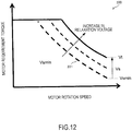
- FIG. 12 is a conceptual diagram showing one example of a relaxation voltage map stored in the relaxation voltage computation unit 220.
- a horizontal axis indicates a motor rotation speed
- a vertical axis indicates a motor requirement torque.
- the relaxation voltage lower limit Vsmin is set as the stack lower limit voltage.
- a value Vs larger than the relaxation voltage lower limit Vsim is set as the stack lower limit voltage.
- the stack lower limit voltage computation unit 200 outputs the relaxation voltage Vs lower than the INV performance guarantee voltage Vt as the stack lower limit voltage to the converter control voltage computation unit 130.
- the relaxation voltage computation unit 220 obtains the relaxation voltage lower limit Vsmin on the basis of the motor output under the INV performance guarantee voltage Vt, and increases the relaxation voltage Vs only when an acceleration request from the driver cannot be fulfilled with the obtained relaxation voltage lower limit Vsmin.
- the stack current can be increased while suppressing a reduction in the output from the driving motor 5 compared with a case where the stack voltage is restricted to the INV performance guarantee voltage Vt. Therefore, the fuel cell stack 1 can promptly shift to the wet state while suppressing a reduction in the drivability during the acceleration.
- the following describes a method of setting the relaxation voltage Vs when an acceleration request received from the driver cannot be fulfilled with the relaxation voltage lower limit Vsmin.
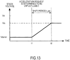
- FIG. 13 is a time chart showing one example of a method of shifting from the relaxation voltage lower limit Vsmin to the relaxation voltage Vs.
- the motor requirement torque Treq is smaller than the motor upper limit torque Tmax, and the relaxation voltage lower limit Vsmin is set as the stack lower limit voltage.
- the relaxation voltage computation unit 220 determines that the acceleration request from the driver cannot be fulfilled, refers to the relaxation voltage map shown in FIG. 12 , and calculates the relaxation voltage Vs corresponding to an operation point specified by the motor requirement torque Treq and the motor rotation speed.
- the relaxation voltage computation unit 220 takes a preset shift period t_sw to monotonically increase the stack lower limit voltage from the relaxation voltage lower limit Vsmin. By thus increasing the relaxation voltage gradually, the upper limit of torque that can be output from the driving motor 5 can be increased while advancing humidification of the fuel cell stack 1.
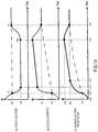
- FIG. 14 is time charts each showing a change in the state of the fuel cell stack 1 when the relaxation voltage Vs is set as the stack lower limit voltage.
- FIG. 14(a) shows a change in the stack voltage detected by the stack voltage sensor 12.
- FIG. 14(b) shows a change in the stack current detected by the stack current sensor 11.
- FIG. 14(c) shows a change in power output from the fuel cell stack 1 on the basis of the stack voltage and the stack current.
- FIG. 14(a) to 14(c) represent a common time axis.
- a solid line indicates a state where the relaxation voltage Vs is set as the stack lower limit voltage
- a dash-and-dot line indicates a state where, instead of the relaxation voltage Vs, the INV performance guarantee voltage Vt is set as the stack lower limit voltage.
- the fuel cell system 100 is activated.
- the relaxation voltage Vt that can achieve the motor requirement torque on the basis of an acceleration request from the driver is set as the stack lower limit voltage.
- the DC/DC converter 3 reduces the stack voltage as shown in FIG. 14(a) , and the stack current consequently increases as shown in FIG. 14(b) . As a result, the power output from the stack increases as shown in FIG. 14(c) .
- the reduced stack voltage reaches the INV performance guarantee voltage Vt.
- the stack current is restricted to a value Is that is smaller than a rated current It as shown in FIG. 14(b) .
- the reduced stack voltage reaches the relaxation voltage Vs, and the stack current exhibits a significant increase from a restriction current Is to the point where it exceeds the rated current It as shown in FIG. 14(b) .
- the I-V characteristic recovers promptly, and the power output from the stack increases quickly compared with a case where the stack voltage is maintained at the INV performance guarantee voltage Vt as shown in FIG. 14(c) .
- a period from time t1 to time t2 is approximately one second.
- the power output from the stack reaches the rated power Pt for the driving motor 5 as shown in FIG. 14(c) .
- a high stack current is maintained as shown in FIG. 14(b) , a large amount of generated water places the electrolyte membranes of the fuel cell stack 1 in a wetter state, thereby further improving the I-V characteristic. Therefore, the power output from the stack gradually increases as shown in FIG. 14(c) .
- the relaxation voltage computation unit 220 executes processing for reverting the stack lower limit voltage from the relaxation voltage Vs to the INV performance guarantee voltage Vt.
- a predetermined shift period is set to gradually increase the stack lower limit voltage, similarly to the shift method shown in FIG. 13 .
- the stack lower limit voltage reverts to the INV performance guarantee voltage Vt as shown in FIG. 14(a) , and the processing for reverting the stack lower limit voltage is ended.
- the foregoing present embodiment has provided an example in which the fuel cell stack 1 supplies power to the driving motor 5.
- the battery 2 also supplies power to the driving motor 5 to secure the responsiveness of the driving motor 5 as shown in FIG. 15 .
- FIG. 15 shows power that can be supplied by the fuel cell system 100 when the stack lower limit voltage has been relaxed in a case where the battery 2 is used to assist the fuel cell stack 1.
- a horizontal axis indicates time, whereas a vertical axis indicates power that the fuel cell system 100 can supply to the driving motor 5. Furthermore, a solid line indicates power exhibited when the relaxation voltage Vs is set as the stack lower limit voltage, whereas a dash-and-dot line indicates power exhibited when the INV performance guarantee voltage Vt is set as the stack lower limit voltage.
- the driving motor 5 is started, and the DC/DC converter 3 causes discharge of assist power from the battery 2 to the driving motor 5, and reduces the stack voltage to gradually output generated power from the fuel cell stack 1 to the driving motor 5.
- the responsiveness of the driving motor 5 can be secured.
- the stack voltage reaches the INV performance guarantee voltage Vt, and the fuel cell stack 1 outputs the restriction power Ps.
- the stack voltage is reduced to the relaxation voltage Vs.
- the stack current increases, and a large amount of water is generated in the fuel cell stack 1.
- the electrolyte membranes of the fuel cell stack 1 are humidified quickly. Therefore, the I-V characteristic recovers, resulting in a prompt increase in generated power of the fuel cell stack 1. Then, at time t22, the rated power Pt can be supplied to the driving motor 5.
- the fuel cell system 100 includes the fuel cell stack 1, the battery 2, and the inverter 4 that converts power output from the fuel cell stack 1 into alternating-current power and supplies the alternating-current power to the driving motor 5.
- the fuel cell system 100 also includes the converter 3 that controls voltage between the fuel cell stack 1 and the inverter 4 using power output from the battery 2.
- the fuel cell system 100 further includes the converter control voltage computation unit 130 and the stack lower limit voltage computation unit 200.
- the converter control voltage computation unit 130 controls the converter 3 so that the voltage between the fuel cell stack 1 and the inverter 4 does not fall below the INV performance guarantee voltage Vt, which is the voltage lower limit of the inverter 4.
- the stack lower limit voltage computation unit 200 causes the voltage between the fuel cell stack 1 and the inverter 4 to fall below the INV performance guarantee voltage Vt.
- the stack lower limit voltage computation unit 200 restricts the act of reducing the voltage between the fuel cell stack 1 and the inverter 4 below the INV performance guarantee voltage Vt.
- the voltage between the fuel cell stack 1 and the inverter 4 is simply referred to as "stack voltage.”
- the stack voltage is controlled so as not to fall below the INV performance guarantee voltage Vt.
- the torque of the driving motor 5 is reduced as shown in FIG. 4 , thereby reducing the drivability.
- a reduction in the stack lower limit voltage is prohibited to suppress an unnecessary reduction in the drivability.
- the relaxation voltage computation unit 220 refers to the relaxation voltage map shown in FIG. 12 , and calculates the relaxation voltage Vs that is lower than the INV performance guarantee voltage Vt and capable of achieving the motor requirement torque without reducing the motor rotation speed during the acceleration. Then, the lower limit voltage setting unit 230 sets the relaxation voltage Vs as the stack lower limit voltage.
- the relaxation voltage computation unit 220 calculates the relaxation voltage lower limit Vsmin on the basis of output produced by the driving motor 5 while the stack voltage is maintained so as not to fall below the INV performance guarantee voltage Vt.
- the stack lower limit voltage setting unit 230 prohibits the act of reducing the stack lower limit voltage to the relaxation voltage lower limit Vsmin if the motor output is reduced compared with a case where the stack voltage is maintained at the INV performance guarantee voltage Vt.
- the stack lower limit voltage setting unit 230 may set the stack voltage to the INV performance guarantee voltage Vt instead of reducing the stack voltage. In this way, a reduction in the drivability can be suppressed with a simple configuration while suppressing the computation load.
- the stack lower limit voltage computation unit 200 gradually increases the voltage between the fuel cell stack 1 and the inverter 4 after causing the stack voltage to fall below the INV performance guarantee voltage Vt. This can increase the upper limit torque of the driving motor 5 while humidifying the electrolyte membranes of the fuel cell stack 1.
- the stack lower limit voltage computation unit 200 takes the predetermined shift period t_sw to revert the stack voltage to the INV performance guarantee voltage Vt. In this way, the drivability can be improved with a simple control configuration. Note that the stack lower limit voltage computation unit 200 may revert the stack lower limit voltage at a predetermined temporal change rate.
- the stack lower limit voltage setting unit 230 switches the stack lower limit voltage to the INV performance guarantee voltage Vt in accordance with the wet/dry state of the fuel cell stack 1.
- the HFR is used to indicate the wet/dry state of the fuel cell stack 1.
- the fuel cell system 100 may include a sensor that measures the humidity of gas discharged from the fuel cell stack 1, and the stack lower limit voltage may be reverted to the INV performance guarantee voltage Vt in accordance with a detected value output from that sensor.
- the stack lower limit voltage setting unit 230 may estimate the I-V characteristic of the fuel cell stack 1, and the stack lower limit voltage may be reverted to the INV performance guarantee voltage Vt on the basis of the estimated I-V characteristic.
- the stack lower limit voltage computation unit 200 gradually increases the stack lower limit voltage to the relaxation voltage Vs.
- the acceleration request from the driver can be fulfilled while suppressing a sudden fluctuation in the torque of the driving motor 5.
- the drivability can be secured during the acceleration.
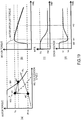
- FIG. 16 shows one example of processing for reverting the stack lower limit voltage according to a second embodiment of the present invention.
- FIG. 16(a) is a diagram of a control method for the driving motor 5 to reduce acceleration vibration G of the vehicle.
- FIG. 16(a) shows the torque characteristics 501 and 502 shown in FIG. 7 in correspondence with the motor rotation speed, as well as the road load (RL) characteristic.
- FIG. 16(b) shows a temporal change in the motor torque with the reduced acceleration vibration G.
- a solid line indicates a change in the torque of the driving motor 5
- a dash line indicates a motor upper limit torque.
- FIG. 16(c) shows a change in the HFR of the fuel cell stack 1.
- FIG. 16(d) shows a change in the stack voltage.
- Horizontal axes in FIG. 16(b) to 16(d) represent a common time axis.
- the driver depresses the accelerator pedal, and a motor requirement torque Ts is calculated.
- the HFR is higher than the dry determination threshold Rw as shown in FIG. 16(c)
- the relaxation voltage Vs that can achieve the motor requirement torque Ts is computed.
- the relaxation voltage Vs is set as the stack lower limit voltage, and the DC/DC converter 3 accordingly reduces the stack voltage to the relaxation voltage Vs lower than the INV performance guarantee voltage Vt. As a result, the driving motor 5 reaches an operation point corresponding to time t31 as shown in FIG. 16(a) .
- a shift period from time t31 to time t32 is set so that the driving motor 5 shifts to an operation point corresponding to time t32 while maintaining the motor torque at time t31 constant.
- the stack lower limit voltage computation unit 200 calculates the shift period t_sw on the basis of the vehicle inertia J converted into the motor shaft output, RLini at the initial stage of the acceleration, the range of change d ⁇ of the motor rotation speed, and the motor torque Ts as indicated by the following expression.
- t _ s w J d ⁇ T s ⁇ R L i n i
- the stack lower limit voltage computation unit 200 gradually increases the stack voltage to the INV performance guarantee voltage Vt in the shift period t_sw from time t31, at which the stack voltage reaches the relaxation voltage Vs, to time t32.
- the motor torque is maintained constant as shown in FIG. 16(b) . This can reduce the acceleration vibration of the vehicle, and alleviate the sense of discomfort felt by the driver during the acceleration.
- the shift period t_sw is preset to reduce the acceleration vibration G of the vehicle, and immediately after the stack voltage reaches the relaxation voltage Vs, the shift period t_sw is taken to shift the stack voltage from the relaxation voltage Vs to the INV performance guarantee voltage Vt.
- the motor torque is maintained constant during the shift period t_sw, thereby reducing the acceleration vibration G of the vehicle.
- the sense of sudden acceleration felt by the driver can be alleviated with such a simple configuration, the drivability can be improved.
- the configuration of the fuel cell system according to the present embodiment differs in the substance of the stack lower limit voltage computation processing executed in step S910 of FIG. 8 .
- other constituents are the same as their counterparts in the first embodiment, they are given the same reference signs thereas, and a description thereof is omitted.
- FIG. 17 is a flowchart of the stack lower limit voltage computation processing according to the present embodiment.
- step S941 the stack lower limit voltage computation unit 200 reads in the HFR measured by the internal resistance measuring apparatus 6.
- the stack lower limit voltage computation unit 200 computes the relaxation voltage Vs on the basis of the HFR.
- the stack lower limit voltage computation unit 200 refers to a preset stack lower limit voltage map, and calculates the relaxation voltage Vs corresponding to the HFR. The details of the stack lower limit voltage map will be described later with reference to FIG. 18 .
- step S943 the stack lower limit voltage computation unit 200 sets the relaxation voltage Vs as the stack lower limit voltage.
- FIG. 18 shows one example of the stack lower limit voltage map stored in the stack lower limit voltage computation unit 200.
- a horizontal axis indicates the HFR
- a vertical axis indicates the relaxation voltage.
- the INV performance guarantee voltage Vt is set as the stack lower limit voltage when the HFR is smaller than Rw, that is, when the fuel cell stack 1 is in the wet state.
- the relaxation voltage Vs is set as the stack lower limit voltage.
- FIG. 19 is time charts each showing a change in the relaxation voltage based on the HFR of the fuel cell stack 1 according to the present embodiment.
- FIG. 19(a) to 19(d) Vertical and horizontal axes in FIG. 19(a) to 19(d) is the same as those in FIG. 16(a) to 16(d) , respectively.
- the horizontal axes in FIG. 19(a) to 19(d) represent a common time axis.
- the driver depresses the accelerator pedal. Then, as shown in FIG. 19(d) , the DC/DC converter 3 reduces the stack voltage to the relaxation voltage Vs that is determined using the map.
- the relaxation voltage Vs is set using the map
- the motor torque gradually decreases due to somewhat insufficient humidification of the fuel cell stack 1 as shown in FIG. 19(b) .
- the drivability experienced by the driver is somewhat reduced.
- the relaxation voltage Vs can be appropriately set in accordance with a wetness degree of the electrolyte membranes at the time of issuance of an acceleration request.
- the following describes a configuration of a fuel cell system according to a fourth embodiment of the present invention.
- the configuration of the fuel cell system according to the present embodiment differs in the substance of the stack lower limit voltage computation processing executed in step S910 of FIG. 8 .
- other constituents are the same as their counterparts in the first embodiment, they are given the same reference signs thereas, and a description thereof is omitted.
- FIG. 20 is a flowchart of the stack lower limit voltage computation processing according to the present embodiment.
- steps S951 to S953 are shown in place of steps S911 and S912 shown in FIG. 9 .
- steps S911 and S912 shown in FIG. 9 .
- step S951 the stack lower limit voltage setting unit 230 reads in the stack current detected by the stack current sensor 11 and the stack voltage detected by the stack voltage sensor 12.
- step S952 the stack lower limit voltage setting unit 230 determines whether the stack voltage is equal to the INV performance guarantee voltage Vt. If the stack voltage is higher than the INV performance guarantee voltage Vt, processing proceeds to step S913.
- the stack lower limit voltage setting unit 230 determines whether the stack current is smaller than the rated current It in step S953.
- step S913 If the stack current is larger than the rated current It, it is determined that the fuel cell stack 1 is in the wet state, and processing proceeds to step S913. On the other hand, if the stack voltage is equal to the INV performance guarantee voltage Vt and the stack current is smaller than the rated current It, it is determined that the fuel cell stack 1 is in the dry state, and processing proceeds to step S920.
- the stack current and the stack voltage are used, in place of the HFR of the fuel cell stack 1, to estimate the wet/dry state of the fuel cell stack 1. Therefore, a poor I-V characteristic can be determined more accurately. This makes it possible to accurately set the relaxation voltage Vs as the stack lower limit voltage.
- the stack lower limit voltage computation unit 200 sets the relaxation voltage Vs as the stack lower limit voltage when the output power of the fuel cell stack 1 is smaller than the power Pt required from the fuel cells, which is computed on the basis of the motor requirement torque. That is, the stack lower limit voltage computation unit 200 sets the relaxation voltage Vs as the stack lower limit voltage in accordance with power output from the fuel cell stack 1.
- the stack lower limit voltage setting unit 230 sets the relaxation voltage Vs as the stack lower limit voltage so as to make the stack current exceed the rated current It.
Landscapes
- Engineering & Computer Science (AREA)
- Life Sciences & Earth Sciences (AREA)
- Sustainable Development (AREA)
- Sustainable Energy (AREA)
- Mechanical Engineering (AREA)
- Transportation (AREA)
- Power Engineering (AREA)
- Chemical & Material Sciences (AREA)
- Chemical Kinetics & Catalysis (AREA)
- Electrochemistry (AREA)
- General Chemical & Material Sciences (AREA)
- Manufacturing & Machinery (AREA)
- Fuel Cell (AREA)
- Electric Propulsion And Braking For Vehicles (AREA)
Abstract
Description
- The present invention relates to a fuel cell system that supplies power output from fuel cells to a motor via an inverter, and a control method for the fuel cell system.
-
JP 5062518B - In such a fuel cell system, with an increase in power required from the fuel cells in response to an accelerator pedal operation, power output from the fuel cells to a motor is increased by reducing the voltage of the fuel cells.
- However, when electrolyte membranes of the fuel cells are in a dry state, even if the voltage of the fuel cells is reduced to a voltage lower limit of the inverter upon receiving an acceleration request from a driver, power supplied from the fuel cells to the motor is insufficient due to a poor I-V characteristic of the fuel cells.
- In this state, as current output from the fuel cells is restricted, the amount of water vapor generated in the fuel cells is restricted as well, and it takes time to place the electrolyte membranes in a wet state. Therefore, even during the acceleration, that is, while power required by the motor is increasing, the power generation performance of the fuel cells does not recover, and a low drivability state continues.
- The present invention has been made in view of the foregoing issue, and aims to provide a fuel cell system that rapidly improves the power generation performance of fuel cells with an increase in power required by a motor, and a control method for the fuel cell system.
- According to one aspect of the present invention, a fuel cell system includes a battery, a fuel cell configured to generate power in accordance with a load, an inverter configured to convert power output from the fuel cell into alternating-current power and supply the alternating-current power to a motor, and a converter configured to control voltage between the inverter and the fuel cell using power output from the battery. The fuel cell system includes a voltage control unit configured to control the converter such that the voltage between the inverter and the fuel cell does not fall below a voltage lower limit of the inverter, and a lower limit voltage control unit configured to, when power required by the motor increases, cause the voltage between the inverter and the fuel cell to fall below the voltage lower limit of the inverter.
-
-
FIG. 1 shows a configuration of a fuel cell system according to a first embodiment of the present invention. -
FIG. 2 is a block diagram showing a functional configuration of a controller that controls the fuel cell system. -
FIG. 3 shows an I-V characteristic that changes in accordance with a wet/ dry state of a fuel cell stack. -
FIG. 4 is a block diagram showing a configuration for computing a lower limit voltage of the fuel cell stack. -
FIG. 5 shows a torque characteristic of a driving motor. -
FIG. 6 shows a method of calculating relaxation voltage for relaxing the lower limit voltage of the fuel cell stack. -
FIG. 7 is a conceptual diagram showing a torque range that can be achieved by reducing voltage of the fuel cell stack to the relaxation voltage. -
FIG. 8 is a flowchart of a control method for the fuel cell system according to the first embodiment. -
FIG. 9 is a flowchart of processing for computing the lower limit voltage of the fuel cell stack. -
FIG. 10 is a flowchart of processing for relaxing the lower limit voltage of the fuel cell stack. -
FIG. 11 is a flowchart of processing for determining whether an acceleration request from a driver can be fulfilled. -
FIG. 12 shows a map used to set the relaxation voltage lower than an INV performance guarantee voltage. -
FIG. 13 is a time chart showing a method of shifting from a lower limit of the relaxation voltage to a voltage that can achieve a motor requirement torque. -
FIG. 14 is time charts each showing a change in the power generation performance of the fuel cell stack when voltage of the fuel cell stack has been reduced to the relaxation voltage during the acceleration of a vehicle. -
FIG. 15 is a time chart showing power that can be supplied to the driving motor when the battery is used to assist the power generation of the fuel cell stack. -
FIG. 16 shows a method of reverting the lower limit voltage of the fuel cell stack according to a second embodiment of the present invention. -
FIG. 17 is a flowchart of stack lower limit voltage computation processing according to a third embodiment of the present invention. -
FIG. 18 shows a map indicating a relationship between the HFR and lower limit voltage of the fuel cell stack. -
FIG. 19 shows the lower limit voltage of the fuel cell stack that changes in accordance with the HFR. -
FIG. 20 is a flowchart of stack lower limit voltage computation processing according to a fourth embodiment of the present invention. - Embodiments of the present invention will be described below with reference to the drawings and the like.
-
FIG. 1 shows a configuration of afuel cell system 100 according to a first embodiment of the present invention. - The
fuel cell system 100 is a power source system that supplies cathode gas and anode gas from outside to afuel cell stack 1, and causes thefuel cell stack 1 to generate power in accordance with electric loads. In the present embodiment, thefuel cell system 100 is mounted in a vehicle. - The
fuel cell system 100 includes thefuel cell stack 1, abattery 2, a DC/DC converter 3, an inverter 4, adriving motor 5, an internalresistance measuring apparatus 6, and acontroller 7. - The
fuel cell stack 1 is a lamination battery made by laminating several hundred fuel cells. Thefuel cell stack 1 generates power using anode gas and cathode gas supplied thereto. Thefuel cell stack 1 has apositive electrode terminal 1A and anegative electrode terminal 1B, respectively at the cathode electrode side and the anode electrode side, as electrode terminals for extracting power. - Each fuel cell is composed of an anode electrode (fuel electrode), a cathode electrode (oxidant electrode), and an electrolyte membrane interposed between the anode electrode and the cathode electrode. At the electrolyte membranes of the fuel cells, electrochemical reactions are caused by anode gas (fuel gas) containing hydrogen, which is supplied to the anode electrodes, and by cathode gas (oxidant gas) containing oxygen, which is supplied to the cathode electrodes. The following electrochemical reactions proceed at the anode electrodes and the cathode electrodes.
(1) Anode electrodes: 2H2 → 4H+ + 4e-
(2) Cathode electrodes: 4H+ + 4e- + O2 → 2H2O
- The foregoing electrochemical reactions (1) and (2) generate an electromotive force and water. In the
fuel cell stack 1, the laminated fuel cells are connected in series. Thus, the sum of cell voltages generated in the fuel cells is the output voltage of the fuel cell stack 1 (e.g., several hundred volts). - A cathode gas supplying/discharging apparatus and an anode gas supplying/discharging apparatus, which are not illustrated, respectively supply cathode gas and anode gas to the
fuel cell stack 1. - The cathode gas supplying/discharging apparatus supplies cathode gas to the
fuel cell stack 1, and discharges cathode off-gas discharged from thefuel cell stack 1 to the outer air. The cathode gas supplying/discharging apparatus is composed of, for example, a compressor that supplies cathode gas, and a pressure control valve that controls cathode gas pressure. - The anode gas supplying/discharging apparatus supplies anode gas to the
fuel cell stack 1, and discharges anode off-gas from thefuel cell stack 1. The anode gas supplying/discharging apparatus is composed of, for example, a pressure control valve that supplies anode gas from a high-pressure tank storing anode gas to thefuel cell stack 1, and a purge valve that discharges anode off-gas from the fuel cell stack. - The
fuel cell stack 1 is connected to the inverter 4 and to the DC/DC converter 3. Thefuel cell stack 1 supplies power to thedriving motor 5 via the inverter 4, and also to, for example, a non-illustrated auxiliary machine. Examples of the auxiliary machine for thefuel cell stack 1 include a compressor that supplies cathode gas to thefuel cell stack 1, and a pump that circulates cooling water to thefuel cell stack 1. The auxiliary machine is connected between the DC/DC converter 3 and thebattery 2, for example. - A stack
current sensor 11 and astack voltage sensor 12 are connected to thefuel cell stack 1. - The stack
current sensor 11 is connected to thepositive electrode terminal 1A of thefuel cell stack 1, and detects current that the drivingmotor 5 extracts from thefuel cell stack 1. The stackcurrent sensor 11 outputs a detection signal indicating the detected current to thecontroller 7. Hereinafter, current extracted from thefuel cell stack 1 is referred to as "stack current." - The
stack voltage sensor 12 is connected between thepositive electrode terminal 1A and thenegative electrode terminal 1B of thefuel cell stack 1, and detects voltage generated between thepositive electrode terminal 1A and thenegative electrode terminal 1B. Thestack voltage sensor 12 outputs a detection signal indicating the detected voltage to thecontroller 7. Hereinafter, voltage output from thefuel cell stack 1 is referred to as "stack voltage." Sack voltage mentioned herein denotes voltage between thefuel cell stack 1 and the inverter 4. - The
battery 2 is a secondary battery that assists power generation of thefuel cell stack 1, and realized by, for example, a lithium-ion battery. When power of thefuel cell stack 1 is insufficient, thebattery 2 discharges power. - Power generated by the
fuel cell stack 1 is insufficient in some situations. Possible examples of such situations include when power required by the drivingmotor 5 increases, especially when accelerating the vehicle, and when the power generation characteristic of thefuel cell stack 1 has not been improved, for example, immediately after the activation of thefuel cell system 100. - A
battery current sensor 21 and abattery voltage sensor 22 are connected to thebattery 2. Thebattery current sensor 21 is connected to a positive electrode terminal of thebattery 2, and detects current discharged from thebattery 2. Thebattery voltage sensor 22 detects inter-terminal voltage generated between the positive electrode terminal and a negative electrode terminal of thebattery 2. - The DC/
DC converter 3 is connected between thefuel cell stack 1 and thebattery 2. The DC/DC converter 3 is a bidirectional voltage converter that converts both of voltage of thefuel cell stack 1 and voltage of thebattery 2. The DC/DC converter 3 is controlled by thecontroller 7. - The DC/
DC converter 3 increases or reduces voltage between thefuel cell stack 1 and the inverter 4 using power output from thebattery 2, without exceeding a preset voltage range. As voltage of thefuel cell stack 1 is increased or reduced, current output from thefuel cell stack 1, that is, generated power (output current × output voltage), decreases or increases. - The inverter 4 converts power output from at least one of the power sources, that is, the
fuel cell stack 1 and thebattery 2, into alternating-current power, and supplies the alternating-current power to the drivingmotor 5. In the present embodiment, thefuel cell stack 1 supplies power to the inverter 4, and thebattery 2 also supplies power to the inverter 4 via the DC/DC converter 3 as needed. - The driving
motor 5 is an electric motor that is rotated and driven by alternating current output from the inverter 4. In the present embodiment, the drivingmotor 5 is realized by a three-phase alternating-current motor that drives the vehicle. - The driving
motor 5 includes a motorrotation speed sensor 51 that detects a rotation speed of a rotor that composes the drivingmotor 5, and amotor torque sensor 52 that detects the torque of the drivingmotor 5. The motorrotation speed sensor 51 and themotor torque sensor 52 output their respective detection signals to thecontroller 7. - The internal
resistance measuring apparatus 6 measures the internal resistance of thefuel cell stack 1 to detect a wet/dry state of thefuel cell stack 1. - Specifically, the internal
resistance measuring apparatus 6 supplies alternating current having a predetermined frequency to thefuel cell stack 1, and detects output voltage and output current of thefuel cell stack 1. The internalresistance measuring apparatus 6 computes the amplitudes of alternating-current components of the output voltage and the output current of thefuel cell stack 1, and calculates the HFR, that is, the internal resistance, of thefuel cell stack 1 by dividing the amplitude of the output voltage by the amplitude of the output current. - In place of the internal
resistance measuring apparatus 6, the DC/DC converter 3 may supply alternating current having a predetermined frequency to thefuel cell stack 1 and measure the HFR of thefuel cell stack 1 using detection signals from the stackcurrent sensor 11 and thestack voltage sensor 12. The internalresistance measuring apparatus 6 outputs a signal indicating the measured HFR to thecontroller 7. - The
controller 7 is composed of a microcomputer provided with a central processing unit (CPU), a read-only memory (ROM), a random-access memory (RAM), and an input/output (I/O) interface. - The
controller 7 receives, as input, detection signals from the aforementioned internalresistance measuring apparatus 6, stackcurrent sensor 11,stack voltage sensor 12,battery current sensor 21,battery voltage sensor 22, motorrotation speed sensor 51, andmotor torque sensor 52. Thecontroller 7 also receives, as input, detection signal from various other sensors that are necessary for controlling power generation of thefuel cell stack 1. - The other sensors include, for example, a
vehicle speed sensor 71 that measures a vehicle speed, and an acceleratoropening degree sensor 72 that calculates an accelerator opening degree by detecting a depression amount of an accelerator pedal. Although not illustrated, the other sensors also include, for example, a state of charge (SOC) sensor that detects the SOC of thebattery 2, and a key sensor that detects a start request or a stop request for thefuel cell system 100 on the basis of ON/OFF of a start key. - Using the DC/
DC converter 3, thecontroller 7 controls generated power supplied from thefuel cell stack 1 to the inverter 4 on the basis of the detection signals from various sensors. -
FIG. 2 is a block diagram showing a functional configuration of thecontroller 7 that controls thefuel cell system 100. - The
controller 7 includes a motor requirementtorque computation unit 110, a motor requirementpower computation unit 120, a converter controlvoltage computation unit 130, and a stack lower limitvoltage computation unit 200. - The motor requirement
torque computation unit 110 computes the torque required in the drivingmotor 5. Hereinafter, the torque required in the drivingmotor 5 is referred to as the "motor requirement torque" or "requirement torque." - In the present embodiment, the motor requirement
torque computation unit 110 calculates the motor requirement torque on the basis of a vehicle speed detected by thevehicle speed sensor 71 and an accelerator opening degree detected by the acceleratoropening degree sensor 72. - A torque map indicating the relationships among accelerator opening degrees, vehicle speeds, and motor requirement torques is prestored in the motor requirement
torque computation unit 110. Upon obtaining an accelerator opening degree and a vehicle speed, the motor requirementtorque computation unit 110 refers to the torque map, and calculates a motor requirement torque corresponding to an operation point specified by the obtained accelerator opening degree and the vehicle speed. - The motor requirement
torque computation unit 110 outputs the calculated motor requirement torque to the stack lower limitvoltage computation unit 200 and the motor requirementpower computation unit 120. - On the basis of the motor requirement torque, the motor requirement
power computation unit 120 computes generated power that the drivingmotor 5 requires from thefuel cell stack 1. Hereinafter, generated power required from thefuel cell stack 1 is referred to as "motor requirement power." - In the present embodiment, a requirement power map indicating the relationships between motor requirement torques and motor requirement powers is prestored in the motor requirement
power computation unit 120. Upon obtaining the motor requirement torque, the motor requirementpower computation unit 120 refers to the requirement power map, and calculates a motor requirement power corresponding to the obtained motor requirement torque. - The motor requirement
power computation unit 120 also obtains dischargeable power on the basis of the SOC of thebattery 2, subtracts the dischargeable power from the calculated motor requirement power, and outputs a value of the result of subtraction to the converter controlvoltage computation unit 130 as a motor requirement power. When thefuel cell stack 1 supplies generated power to the auxiliary machine, the motor requirementpower computation unit 120 adds power consumed by the auxiliary machine to the motor requirement power, and outputs a value of the result of addition as a motor requirement power. - The stack lower limit
voltage computation unit 200 computes a lower limit voltage of thefuel cell stack 1 on the basis of the motor requirement torque, stack power generation characteristic information, and a motor rotation speed. - The stack power generation characteristic information is a parameter for determining whether the current-voltage characteristic of the
fuel cell stack 1 can achieve the rated power necessary for driving the drivingmotor 5. The rated power denotes an upper limit of power necessary for driving the drivingmotor 5 within a preset range of use. - Examples of the stack power generation characteristic information include a wet/dry state of the electrolyte membranes in the
fuel cell stack 1, the temperature of thefuel cell stack 1, and output power of thefuel cell stack 1. Hereinafter, the current-voltage characteristic of thefuel cell stack 1 is simply referred to as the "I-V characteristic." - When the I-V characteristic of the
fuel cell stack 1 is favorable, the stack lower limitvoltage computation unit 200 outputs a voltage lower limit of the inverter 4 to the converter controlvoltage computation unit 130. The voltage lower limit of the inverter 4 guarantees driving of the drivingmotor 5 within the range of use, and is hereinafter referred to as the "INV performance guarantee voltage." - The converter control
voltage computation unit 130 computes voltage of the DC/DC converter 3 at thefuel cell stack 1 side so that voltage between thefuel cell stack 1 and the inverter 4 does not fall below the INV performance guarantee voltage. - The converter control
voltage computation unit 130 also calculates voltage of the DC /DC converter 3 so that generated power of thefuel cell stack 1 matches the motor requirement power. For example, a product of a detected value of the stackcurrent sensor 11 and a detected value of thestack voltage sensor 12 is used as the generated power of thefuel cell stack 1. - As such, the converter control
voltage computation unit 130 constitutes a voltage control unit that controls the DC/DC converter 3 so that voltage between thefuel cell stack 1 and the inverter 4 does not fall below the INV performance guarantee voltage. - The converter control
voltage computation unit 130 outputs voltage of the DC/DC converter 3 at thefuel cell stack 1 side to the DC/DC converter 3 as stack control voltage. In this way, voltage of thefuel cell stack 1 is adjusted so as to reduce the deviation between generated power of thefuel cell stack 1 and the motor requirement power. - As described above, the
controller 7 obtains the motor requirement power in accordance with the motor requirement torque, and reduces voltage of the DC/DC converter 3 at thefuel cell stack 1 side in accordance with the obtained motor requirement power. In this way, thefuel cell stack 1 supplies power compliant with a request from the driver to the drivingmotor 5 via the inverter 4. - However, when the I-V characteristic of the
fuel cell stack 1 is not favorable, requirement power necessary for driving the drivingmotor 5 may not be secured even if voltage between thefuel cell stack 1 and the inverter 4 has been reduced to the INV performance guarantee voltage. - The I-V characteristic of the
fuel cell stack 1 deteriorates, for example, when the electrolyte membranes in thefuel cell stack 1 are in a dry state, and when the temperature of thefuel cell stack 1 is below the temperature of a freezing point. - In the foregoing
fuel cell system 100, in order to prevent degradation of the fuel cells due to freezing of generated water that has attached to the electrolyte membranes after stopping thefuel cell stack 1, a drying operation for drying the electrolyte membranes is executed during processing for stopping thefuel cell stack 1. Therefore, at the time of reactivation of the fuel cell system, the electrolyte membranes are in a dry state. -
FIG. 3 shows the I-V characteristics of thefuel cell stack 1 in a wet state and a dry state. InFIG. 3 , a horizontal axis indicates output current of thefuel cell stack 1, whereas a vertical axis indicates output voltage of thefuel cell stack 1. - In
FIG. 3 , a solid line indicates the I-V characteristic exhibited when the electrolyte membranes of thefuel cell stack 1 are wet, that is, in the wet state, whereas a dash-and-dot line indicates the I-V characteristic exhibited when the electrolyte membranes of thefuel cell stack 1 are dry, that is, in the dry state. Herein, the HFR exhibited by thefuel cell stack 1 when the electrolyte membranes are in the wet state is noted as "Rw," whereas the HFR exhibited by thefuel cell stack 1 when the electrolyte membranes are in the dry state is noted as "Rd". - As shown in
FIG. 3 , when thefuel cell stack 1 is in the wet state, thefuel cell stack 1 supplies the rated power Vt to the drivingmotor 5 as soon as the stack voltage reaches the INV performance guarantee voltage Vt. - On the other hand, when the
fuel cell stack 1 is in the dry state, the I-V characteristic is deteriorated compared with that in the wet state; hence, even if the stack voltage has been reduced to the INV performance guarantee voltage Vt, thefuel cell stack 1 does not supply the rated power Vt to the drivingmotor 5 due to the small stack current. - Therefore, when the motor requirement torque has increased with an increase in the depression amount of the accelerator pedal caused by an acceleration request from the driver, the stack voltage reaches the IV performance guarantee voltage Vt before generated power of the
fuel cell stack 1 reaches the motor requirement power. - In this state, merely using power Ps generated under the IV performance guarantee voltage Vt does not supply sufficient power to driving
motor 5. As a result, the vehicle is not sufficiently accelerated in response to the acceleration request from the driver, that is, the drivability is reduced. - Furthermore, as shown in
FIG. 3 , when the stack voltage is increased by the DC/DC converter 3 to prevent the stack voltage from falling below the INV performance guarantee voltage Vt, the stack current is restricted. In general, the smaller the stack current, the smaller the amount of water generated in thefuel cell stack 1 as indicated by the aforementioned electrode reactions (1) and (2). For this reason, while the stack current is restricted by maintaining the stack voltage at the INV performance guarantee voltage Vt, it takes time for the electrolyte membranes to shift from the dry state to the wet state. - Therefore, despite the acceleration request from the driver, the I-V characteristic of the
fuel cell stack 1 does not recover immediately, even during the acceleration of the vehicle. Thus, the drivability is not improved. - In view of the above, in the present embodiment, when the
fuel cell stack 1 has a poor power generation characteristic, voltage between thefuel cell stack 1 and the inverter 4 is reduced to fall below the INV performance guarantee voltage Vt so as to increase the stack current when power required by the drivingmotor 5 increases, for example, when accelerating the vehicle. -
FIG. 4 is a block diagram showing a detailed configuration of the stack lower limitvoltage computation unit 200 according to the present embodiment. - The stack lower limit
voltage computation unit 200 constitutes a lower limit voltage control unit that, with an increase in power required by the drivingmotor 5, controls the DC/DC converter 3 to cause voltage between thefuel cell stack 1 and the inverter 4 to fall below the INV performance guarantee voltage Vt, that is, the voltage lower limit of the inverter 4. - The stack lower limit
voltage computation unit 200 includes an INV voltage lowerlimit holding unit 210, a relaxationvoltage computation unit 220, and a stack lower limitvoltage setting unit 230. - The INV voltage lower
limit holding unit 210 holds the aforementioned INV performance guarantee voltage Vt. The INV performance guarantee voltage Vt is determined on the basis of the rated power Pt for the drivingmotor 5, and is preset in accordance with, for example, the conditions of use of the drivingmotor 5 and the power generation performance of thefuel cell stack 1. - For example, as shown in
FIG. 3 , the INV performance guarantee voltage Vt is set as a stack voltage that enables thefuel cell stack 1 to supply the rated power Pt, which is necessary for accelerating the drivingmotor 5, to the inverter 4 when thefuel cell stack 1 is in the wet state. - The relaxation
voltage computation unit 220 computes a relaxation voltage Vs for relaxing the voltage restriction based on the INV performance guarantee voltage Vt. In the present embodiment, the relaxationvoltage computation unit 220 calculates the relaxation voltage Vs, which is lower than the INV performance guarantee voltage Vt, on the basis of the motor requirement torque and motor rotation speed. - The stack lower limit
voltage setting unit 230 sets a lower limit of the stack voltage controlled by the DC/DC converter 3. Hereinafter, the voltage lower limit set by the stack lower limitvoltage setting unit 230 is referred to as the "stack lower limit voltage." - In the present embodiment, the stack lower limit
voltage setting unit 230 determines whether thefuel cell stack 1 is in the dry state on the basis of the HFR measured by the internalresistance measuring apparatus 6. - When it is determined that the
fuel cell stack 1 is in the wet state, the stack lower limitvoltage setting unit 230 sets the INV performance guarantee voltage Vt as the stack lower limit voltage. On the other hand, when it is determined that thefuel cell stack 1 is in the dry state, the stack lower limitvoltage setting unit 230 sets the relaxation voltage, which is lower than the INV performance guarantee voltage Vt, as the stack lower limit voltage. -
FIG. 5 shows a torque characteristic of the drivingmotor 5 in correspondence with a motor rotation speed. This torque characteristic changes in accordance with a reduction in the stack voltage. InFIG. 5 , a horizontal axis indicates the motor rotation speed, whereas a vertical axis indicates the motor torque. - In
FIG. 5 , a solid line indicates atorque characteristic 501 exhibited when the rated power Pt is supplied to the drivingmotor 5 while the stack voltage is set to the INV performance guarantee voltage Vt. - In general, as indicated by dash-and-dot lines, the torque characteristic of the driving
motor 5 deteriorates with a reduction in power supplied to the drivingmotor 5. Furthermore, even if power supplied to the drivingmotor 5 is constant, the torque characteristic deteriorates as the stack voltage falls below the INV performance guarantee voltage Vt. - Therefore, setting the relaxation voltage Vs to be excessively lower than the INV performance guarantee voltage Vt causes excessive deterioration in the torque characteristic. In this case, even if the driver issues an acceleration request to increase the motor requirement torque, the increased motor requirement torque cannot be achieved, and the drivability is significantly reduced.
- With reference to
FIGs. 6(a) to 6(d) , a description is now given of a method of setting a lower limit of the relaxation voltage Vs as a countermeasure against the foregoing issue. -
FIGs. 6(a) to 6(d) show a method of computing a relaxation voltage lower limit Vsmin in the relaxationvoltage computation unit 220. -
FIG. 6(a) shows the I-V characteristics of thefuel cell stack 1 in the dry state and the wet state.FIG. 6(b) shows the characteristics of powers generated by thefuel cell stack 1 in the dry state and the wet state in correspondence with the stack current. InFIGs. 6(a) and 6(b) , solid lines indicate the characteristics in the wet state, whereas dash lines indicate the characteristics in the dry state. -
FIG. 6(c) shows the torque characteristic and the output characteristic of the drivingmotor 5 in correspondence with a rotation speed. InFIG. 6(c) , a solid line indicates the torque characteristic, whereas a dash-and-dot line indicates the output characteristic.FIG. 6(d) shows a relationship between voltage of the drivingmotor 5 and a rotation speed of the drivingmotor 5. - When the DC/
DC converter 3 maintains the stack voltage at the INV performance guarantee voltage Vt while thefuel cell stack 1 is in the dry state as indicated by the dash line inFIG. 6(a) , power generated by the stack is restricted to power Ps as indicated by the dash line inFIG. 6(b) . - As shown in
FIG. 6(c) , a rotation speed exhibited by the drivingmotor 5 when thefuel cell stack 1 supplies the restriction power Ps to the drivingmotor 5 is specified from the output characteristic of the drivingmotor 5. As shown inFIG. 6(d) , voltage of the drivingmotor 5 is obtained from the specified rotation speed of the drivingmotor 5. As shown inFIG. 6(a) , the lower limit Vsmin of the relaxation voltage is specified from the obtained voltage of the drivingmotor 5. - As described above, on the basis of the restriction power Ps exhibited when the stack voltage is restricted to the INV performance guarantee voltage Vt, the lower limit Vsmin of the relaxation voltage is set so that the shaft output of the driving
motor 5 does not fall below the motor output under the restriction power Ps. - In this way, when accelerating the driving
motor 5, the amount of water generated in thefuel cell stack 1 can be significantly increased without causing the output of the drivingmotor 5 to fall below the motor output exhibited when the stack voltage is restricted to the INV performance guarantee voltage Vt. - Therefore, humidification of the
fuel cell stack 1 can be advanced without reducing the output of the drivingmotor 5 at the time of acceleration compared with a case where the INV performance guarantee voltage Vt is set as the stack lower limit voltage. -
FIG. 7 is a conceptual diagram showing an achievable motor torque range that is expanded by relaxing the stack lower limit voltage. -
FIG. 7 shows thetorque characteristic 501 shown inFIG. 5 , atorque characteristic 502 exhibited when the restriction power Ps is supplied to the drivingmotor 5 while the stack voltage is set to the relaxation voltage Vs, anupper limit torque 510 exhibited when the stack lower limit voltage is relaxed, and anupper limit torque 520 exhibited when the stack lower limit voltage is not relaxed. - The
torque characteristic 502 corresponds to a motor rotation speed exhibited when thefuel cell stack 1 supplies the restriction power Ps to the drivingmotor 5 while the relaxation voltage Vs is set is set between thefuel cell stack 1 and the inverter 4. - The
upper limit torque 510 is an upper limit of the motor torque that can be achieved by reducing the stack voltage, which is supplied from thefuel cell stack 1 to the inverter 4, to the relaxation voltage Vs. Theupper limit torque 520 is an upper limit of the motor torque that can be achieved by restricting the stack voltage to the INV performance guarantee voltage Vt. - As shown in
FIG. 7 , the motor requirement torque increases to theupper limit torque 520 in response to an acceleration request issued by the driver at an operation point OPm. - In this case, while the stack voltage is restricted to the INV performance guarantee voltage Vt, the amount of water generated in the
fuel cell stack 1 is small because the stack current is restricted as shown inFIG. 3 , and thus it takes time to shift from the dry state to the wet state. Therefore, with theupper limit torque 520, a shift from thetorque characteristic 502 to thetorque characteristic 501 is completed when the motor rotation speed exceeds the operation point OPm by a substantial amount. - On the other hand, in the present embodiment, the stack voltage is reduced to the relaxation voltage Vs, and thus the stack current increases, and so does the amount of generated water in the
fuel cell stack 1. Accordingly, thefuel cell stack 1 shifts from the dry state to the wet state in a short period of time. That is, theupper limit torque 510 causes a substantially parallel shift to thetorque characteristic 501 immediately after transition from the operation point OPm to thetorque characteristic 502. - As described above, setting the relaxation voltage Vs as the stack lower limit voltage enables the
fuel cell stack 1 to shift from the dry state to the wet state in a short period of time at the time of acceleration. This makes it possible to promptly expand a torque range that can achieve the motor requirement torque from a range under theupper limit torque 520 to a range under theupper limit torque 510. - Therefore, the power generation performance of the
fuel cell stack 1 is improved in a short period of time during the acceleration of the vehicle. Thus, a reduction in the drivability during the acceleration can be promptly reversed. - A description is now given of the operations of the
controller 7 according to the present embodiment with reference to the drawings. -
FIG. 8 is a flowchart of a control method for thefuel cell system 100 according to the present embodiment. - In step S901, the motor requirement
torque computation unit 110 of thecontroller 7 reads in an accelerator opening degree and a vehicle speed that are detected by the acceleratoropening degree sensor 72 and thevehicle speed sensor 71, respectively. - In step S902, the motor requirement
torque computation unit 110 refers to the prestored torque map after reading in the accelerator opening degree and the vehicle speed, and calculates a motor requirement torque Treq corresponding to an operation point specified by these accelerator opening degree and vehicle speed. - In step S903, the motor requirement
power computation unit 120 of thecontroller 7 refers to the prestored requirement power map after obtaining the motor requirement torque, and calculates a motor requirement power corresponding to the obtained motor requirement torque Treq. - In step S910, the stack lower limit
voltage computation unit 200 of thecontroller 7 executes stack lower limit voltage processing for setting the stack lower limit voltage. The stack lower limit voltage processing will be described later with reference toFIG. 9 . - In step S904, the converter control
voltage computation unit 130 of thecontroller 7 computes voltage of the DC/DC converter 3 at thefuel cell stack 1 side on the basis of the motor requirement power so that the voltage does not fall below the stack lower limit voltage. - In the present embodiment, the converter control
voltage computation unit 130 reduces the voltage of the DC/DC converter 3 at thefuel cell stack 1 side so that power output from thefuel cell stack 1 matches the motor requirement power. When the voltage of the DC/DC converter 3 at thefuel cell stack 1 side has reached the stack lower limit voltage, the converter controlvoltage computation unit 130 restricts the voltage of thefuel cell stack 1 to the stack lower limit voltage. -
FIG. 9 is a flowchart of one example of the stack lower limit voltage processing executed in step S910. - In step S911, the stack lower limit
voltage setting unit 230 of the stack lower limitvoltage computation unit 200 reads in the HFR, which is correlated with a wetness degree of the electrolyte membranes of thefuel cell stack 1, from the internalresistance measuring apparatus 6. The higher the HFR of thefuel cell stack 1, the drier the electrolyte membranes. The lower the HFR of thefuel cell stack 1, the wetter the electrolyte membranes. Note that the temperature of thefuel cell stack 1, for example, may be used in place of the HFR as a parameter correlated with the wetness degree of the electrolyte membranes. - In step S912, the stack lower limit
voltage setting unit 230 determines whether the HFR is equal to or higher than a dry determination threshold Rw. As indicated by the solid line inFIG. 3 , the dry determination threshold Rw is set to an upper limit of the HFR in the wet state where thefuel cell stack 1 can supply the rated power for the drivingmotor 5 while the voltage of thefuel cell stack 1 is set to the INV performance guarantee voltage Vt. - If the HFR is equal to or higher than the dry determination threshold Rw, the stack lower limit
voltage setting unit 230 of thecontroller 7 proceeds to step S920, determines that the INV performance guarantee voltage Vt would restrict the stack voltage at the time of acceleration, and executes processing for relaxing the stack lower limit voltage. The details of the stack lower limit voltage processing will be described later with reference toFIG. 10 . - If the HFR is lower than the dry determination threshold Rw, the stack lower limit
voltage setting unit 230 proceeds to step S913, determines that thefuel cell stack 1 is in a state where it can supply the rated power Pt to the drivingmotor 5, and sets the INV performance guarantee voltage Vt as the stack lower limit voltage. Thereafter, the present processing returns to the processing procedure of the control method for thefuel cell system 100 shown inFIG. 8 . -
FIG. 10 is a flowchart of one example of the processing executed in step S920, that is, the processing for relaxing the stack lower limit voltage. - In step S921, the relaxation
voltage computation unit 220 of the stack lower limitvoltage computation unit 200 computes the relaxation voltage lower limit Vsmin on the basis of the restriction power Ps under the INV performance guarantee voltage Vt. - In the present embodiment, as shown in
FIGs. 6(a) and 6(b) , I-V characteristics are prestored in the relaxationvoltage computation unit 220 in one-to-one correspondence with HFRs of thefuel cell stack 1. The relaxationvoltage computation unit 220 obtains a stack current under the INV performance guarantee voltage Vt with reference to the I-V characteristic specified by the current HFR, and calculates the restriction power Ps by multiplying the obtained stack current by the INV performance guarantee voltage Vt. - The relaxation
voltage computation unit 220 may estimate the I-V characteristic using the stackcurrent sensor 11 and thestack voltage sensor 12, and calculate the restriction power Ps by obtaining a stack current under the INV performance guarantee voltage Vt on the basis of the estimated I-V characteristic. - Furthermore, as shown in
FIG. 6(c) and 6(d) , output characteristics and voltage characteristics of the drivingmotor 5 are prestored in the relaxationvoltage computation unit 220 in correspondence with motor rotation speeds. The relaxationvoltage computation unit 220 obtains a motor rotation speed under the restriction power Ps with reference to the output characteristic of the drivingmotor 5, and specifies a motor voltage from the obtained motor rotation speed with reference to the voltage characteristic of the drivingmotor 5. - The relaxation
voltage computation unit 220 converts the specified motor voltage into voltage of the inverter 4, and calculates the converted voltage of the inverter 4 as the relaxation voltage lower limit Vsmin of thefuel cell stack 1. - By thus determining the relaxation voltage lower limit Vsmin, the stack current can be increased to advance humidification of the
fuel cell stack 1 without causing the generated power to fall below the restriction power Ps exhibited when the stack voltage is restricted to the INV performance guarantee voltage Vt. - In step S922, the relaxation
voltage computation unit 220 computes a motor upper limit torque Tmax using, for example, a preset map on the basis of the relaxation voltage lower limit Vsmin. As a result, theupper limit torque 520 indicated by the broken line inFIG. 7 is obtained. - In step S930, the relaxation
voltage computation unit 220 executes processing for determining whether the motor requirement torque Treq can be achieved while the stack voltage is set to the relaxation voltage lower limit Vsim. The details of this processing will be described later with reference toFIG. 11 . - In step S923, if the relaxation
voltage computation unit 220 determines that the acceleration request cannot be fulfilled by setting the stack voltage to the relaxation voltage lower limit Vsmin, it proceeds to step S924; on the other hand, if it determines that the acceleration request can be fulfilled, it proceeds to step S926. - In step S924, as the relaxation
voltage computation unit 220 has determined that the acceleration request cannot be fulfilled with the relaxation voltage lower limit Vsmin, it computes a relaxation voltage Vs that can achieve the motor requirement torque Treq. - In the present embodiment, the relaxation
voltage computation unit 220 refers to a preset relaxation voltage map, and computes the relaxation voltage Vs on the basis of the motor requirement torque Treq and the current motor rotation speed detected by the motorrotation speed sensor 51. The details of the relaxation voltage map will be described later with reference toFIG. 12 . - In step S925, the stack lower limit
voltage setting unit 230 sets the relaxation voltage Vs that can achieve the motor requirement torque as the stack lower limit voltage. - In step S926, as the acceleration request can be fulfilled with the output equivalent to the motor output under the restriction power Ps, the stack lower limit
voltage setting unit 230 sets the relaxation voltage lower limit Vsmin as the stack lower limit voltage. Upon completion of the process of step S925 or S926, the processing for relaxing the stack lower limit voltage is ended, and the processing ofFIG. 9 is resumed. -
FIG. 11 shows one example of the processing executed in step S930, that is, the processing for determining whether the acceleration request can be fulfilled. - In step S931, the relaxation
voltage computation unit 220 determines whether the motor requirement torque Treq is larger than the motor upper limit torque Tmax that is set on the basis of the relaxation voltage lower limit Vsmin. - If the motor requirement torque Treq is larger than the motor upper limit torque Tmax, the relaxation
voltage computation unit 220 proceeds to step S932 and determines that the acceleration request cannot be fulfilled with the motor output under the restriction power Ps. - If the motor requirement torque Treq is equal to or smaller than the motor upper limit torque Tmax, the relaxation
voltage computation unit 220 proceeds to step S933 and determines that the acceleration request can be fulfilled with the motor output under the restriction power Ps. Upon completion of the processes of steps S932 and S933, the processing for determining whether the acceleration request can be fulfilled is ended, and the processing ofFIG. 10 is resumed. -
FIG. 12 is a conceptual diagram showing one example of a relaxation voltage map stored in the relaxationvoltage computation unit 220. InFIG. 12 , a horizontal axis indicates a motor rotation speed, whereas a vertical axis indicates a motor requirement torque. - As shown in
FIG. 12 , in an operation range within anupper limit torque 221 based on the relaxation voltage lower limit Vsmin, the relaxation voltage lower limit Vsmin is set as the stack lower limit voltage. As the motor requirement torque becomes large compared with theupper limit torque 221, a value Vs larger than the relaxation voltage lower limit Vsim is set as the stack lower limit voltage. - As described above, when the
fuel cell stack 1 is in the dry state, the stack lower limitvoltage computation unit 200 outputs the relaxation voltage Vs lower than the INV performance guarantee voltage Vt as the stack lower limit voltage to the converter controlvoltage computation unit 130. - Specifically, the relaxation
voltage computation unit 220 obtains the relaxation voltage lower limit Vsmin on the basis of the motor output under the INV performance guarantee voltage Vt, and increases the relaxation voltage Vs only when an acceleration request from the driver cannot be fulfilled with the obtained relaxation voltage lower limit Vsmin. - In this way, the stack current can be increased while suppressing a reduction in the output from the driving
motor 5 compared with a case where the stack voltage is restricted to the INV performance guarantee voltage Vt. Therefore, thefuel cell stack 1 can promptly shift to the wet state while suppressing a reduction in the drivability during the acceleration. - With reference to the drawings, the following describes a method of setting the relaxation voltage Vs when an acceleration request received from the driver cannot be fulfilled with the relaxation voltage lower limit Vsmin.
-
FIG. 13 is a time chart showing one example of a method of shifting from the relaxation voltage lower limit Vsmin to the relaxation voltage Vs. - Prior to time t1, the motor requirement torque Treq is smaller than the motor upper limit torque Tmax, and the relaxation voltage lower limit Vsmin is set as the stack lower limit voltage.
- At time t1, the driver issues an acceleration request by increasing the depression amount of the accelerator pedal, and the motor requirement torque Treq exceeds the motor upper limit torque Tmax. Accordingly, the relaxation
voltage computation unit 220 determines that the acceleration request from the driver cannot be fulfilled, refers to the relaxation voltage map shown inFIG. 12 , and calculates the relaxation voltage Vs corresponding to an operation point specified by the motor requirement torque Treq and the motor rotation speed. - Then, in order to switch to the relaxation voltage Vs, the relaxation
voltage computation unit 220 takes a preset shift period t_sw to monotonically increase the stack lower limit voltage from the relaxation voltage lower limit Vsmin. By thus increasing the relaxation voltage gradually, the upper limit of torque that can be output from the drivingmotor 5 can be increased while advancing humidification of thefuel cell stack 1. - At time t2, that is, when the shift period t_sw has elapsed since time t1, the increased stack lower limit voltage reaches the relaxation voltage Vs. Accordingly, the motor requirement torque Treq can be achieved. In this way, a reduction in the drivability can be suppressed while securing the amount of water generated in the
fuel cell stack 1. - By thus setting the shift period t_sw, an acceleration request can be fulfilled while suppressing a sudden fluctuation in the output from the driving
motor 5 associated with the acceleration request. Consequently, the drivability is improved. - A description is now given of the operations of the
fuel cell system 100 when the processing for relaxing the stack lower limit voltage according to the present embodiment has been executed. -
FIG. 14 is time charts each showing a change in the state of thefuel cell stack 1 when the relaxation voltage Vs is set as the stack lower limit voltage. -
FIG. 14(a) shows a change in the stack voltage detected by thestack voltage sensor 12.FIG. 14(b) shows a change in the stack current detected by the stackcurrent sensor 11.FIG. 14(c) shows a change in power output from thefuel cell stack 1 on the basis of the stack voltage and the stack current. - Horizontal axes in
FIG. 14(a) to 14(c) represent a common time axis. In each of these figures, a solid line indicates a state where the relaxation voltage Vs is set as the stack lower limit voltage, whereas a dash-and-dot line indicates a state where, instead of the relaxation voltage Vs, the INV performance guarantee voltage Vt is set as the stack lower limit voltage. - At time t10, the
fuel cell system 100 is activated. At this time, as thefuel cell stack 1 is in the dry state, the relaxation voltage Vt that can achieve the motor requirement torque on the basis of an acceleration request from the driver is set as the stack lower limit voltage. - In response to the acceleration request from the driver, the DC/
DC converter 3 reduces the stack voltage as shown inFIG. 14(a) , and the stack current consequently increases as shown inFIG. 14(b) . As a result, the power output from the stack increases as shown inFIG. 14(c) . - At time t11, the reduced stack voltage reaches the INV performance guarantee voltage Vt. At this time, due to a poor I-V characteristic, the stack current is restricted to a value Is that is smaller than a rated current It as shown in
FIG. 14(b) . - When the stack voltage is restricted to the INV performance guarantee voltage Vt, a small stack current is maintained as indicated by the dash-and-dot line in
FIG. 14(b) , and thus it takes time for thefuel cell stack 1 to enter the wet state with the aid of generated water. This leads to a delay in recovery of the I-V characteristic. That is, the power output from the stack gradually increases as indicated by the dash-and-dot line inFIG. 14(c) . - On the other hand, relaxing the stack lower limit voltage using the relaxation voltage Vs causes the stack voltage to fall below the INV performance guarantee voltage Vt as shown in
FIG. 14(a) . - At time t12, the reduced stack voltage reaches the relaxation voltage Vs, and the stack current exhibits a significant increase from a restriction current Is to the point where it exceeds the rated current It as shown in
FIG. 14(b) . As a large amount of water is consequently generated in thefuel cell stack 1, the I-V characteristic recovers promptly, and the power output from the stack increases quickly compared with a case where the stack voltage is maintained at the INV performance guarantee voltage Vt as shown inFIG. 14(c) . Note that a period from time t1 to time t2 is approximately one second. - At time t13, the power output from the stack reaches the rated power Pt for the driving
motor 5 as shown inFIG. 14(c) . Thereafter, as a high stack current is maintained as shown inFIG. 14(b) , a large amount of generated water places the electrolyte membranes of thefuel cell stack 1 in a wetter state, thereby further improving the I-V characteristic. Therefore, the power output from the stack gradually increases as shown inFIG. 14(c) . - At time t14, the HFR of the
fuel cell stack 1 falls below the wet state Rw shown inFIG. 3 , and the relaxationvoltage computation unit 220 executes processing for reverting the stack lower limit voltage from the relaxation voltage Vs to the INV performance guarantee voltage Vt. Here, a predetermined shift period is set to gradually increase the stack lower limit voltage, similarly to the shift method shown inFIG. 13 . - At time t15, the stack lower limit voltage reverts to the INV performance guarantee voltage Vt as shown in
FIG. 14(a) , and the processing for reverting the stack lower limit voltage is ended. - As described above, by setting the relaxation voltage Vs that is lower than the INV performance guarantee voltage Vt as the stack lower limit voltage, a large amount of water is generated due to a significant increase in the stack current, thereby enabling the
fuel cell stack 1 to supply the rated power Pt in an extremely short period of time. - The foregoing present embodiment has provided an example in which the
fuel cell stack 1 supplies power to the drivingmotor 5. However, when the drivingmotor 5 is started, thebattery 2 also supplies power to the drivingmotor 5 to secure the responsiveness of the drivingmotor 5 as shown inFIG. 15 . -
FIG. 15 shows power that can be supplied by thefuel cell system 100 when the stack lower limit voltage has been relaxed in a case where thebattery 2 is used to assist thefuel cell stack 1. - In
FIG. 15 , a horizontal axis indicates time, whereas a vertical axis indicates power that thefuel cell system 100 can supply to the drivingmotor 5. Furthermore, a solid line indicates power exhibited when the relaxation voltage Vs is set as the stack lower limit voltage, whereas a dash-and-dot line indicates power exhibited when the INV performance guarantee voltage Vt is set as the stack lower limit voltage. - At time t20, the driving
motor 5 is started, and the DC/DC converter 3 causes discharge of assist power from thebattery 2 to the drivingmotor 5, and reduces the stack voltage to gradually output generated power from thefuel cell stack 1 to the drivingmotor 5. By thus using thebattery 2 to assist power generation of thefuel cell stack 1, the responsiveness of the drivingmotor 5 can be secured. - At time t21, the stack voltage reaches the INV performance guarantee voltage Vt, and the
fuel cell stack 1 outputs the restriction power Ps. At this time, as thefuel cell stack 1 is in the dry state, the stack voltage is reduced to the relaxation voltage Vs. As a result, the stack current increases, and a large amount of water is generated in thefuel cell stack 1. - Accordingly, the electrolyte membranes of the
fuel cell stack 1 are humidified quickly. Therefore, the I-V characteristic recovers, resulting in a prompt increase in generated power of thefuel cell stack 1. Then, at time t22, the rated power Pt can be supplied to the drivingmotor 5. - Furthermore, as a period required for the recovery of the I-V characteristic is shortened, an increase in the amount of discharge from the
battery 2 associated with insufficient power generation of thefuel cell stack 1 can be suppressed. This can prevent overdischarge from thebattery 2. - According to the first embodiment of the present invention, the
fuel cell system 100 includes thefuel cell stack 1, thebattery 2, and the inverter 4 that converts power output from thefuel cell stack 1 into alternating-current power and supplies the alternating-current power to the drivingmotor 5. Thefuel cell system 100 also includes theconverter 3 that controls voltage between thefuel cell stack 1 and the inverter 4 using power output from thebattery 2. - The
fuel cell system 100 further includes the converter controlvoltage computation unit 130 and the stack lower limitvoltage computation unit 200. - The converter control
voltage computation unit 130 controls theconverter 3 so that the voltage between thefuel cell stack 1 and the inverter 4 does not fall below the INV performance guarantee voltage Vt, which is the voltage lower limit of the inverter 4. - When power required by the driving
motor 5 increases, for example, when the driver has depressed the accelerator pedal, the stack lower limitvoltage computation unit 200 causes the voltage between thefuel cell stack 1 and the inverter 4 to fall below the INV performance guarantee voltage Vt. - In this way, when the power required by the driving
motor 5 increases in response to, for example, an acceleration request, current extracted from thefuel cell stack 1 increases, and a large amount of water is generated in thefuel cell stack 1. This enables the electrolyte membranes of thefuel cell stack 1 to promptly shift to the wet state. As a result, the power generation performance of thefuel cell stack 1 is improved, and a reduction in the driving performance (drivability) of the vehicle associated with a reduction in the I-V characteristic can be reversed during an acceleration operation. - It is also possible to prevent extraction of an excessive amount of discharged power from the
battery 2 to the inverter 4 via the DC/DC converter 3 in association with a reduction in generated power of thefuel cell stack 1. - Furthermore, in the present embodiment, when the electrolyte membranes of the
fuel cell stack 1 are wet, the stack lower limitvoltage computation unit 200 restricts the act of reducing the voltage between thefuel cell stack 1 and the inverter 4 below the INV performance guarantee voltage Vt. Herein, the voltage between thefuel cell stack 1 and the inverter 4 is simply referred to as "stack voltage." - Specifically, as shown in
FIG. 3 , in the wet state Rw where the rated power Pt can be supplied to the drivingmotor 5 when the stack voltage has been reduced to the INV performance guarantee voltage Vt, the stack voltage is controlled so as not to fall below the INV performance guarantee voltage Vt. - If the stack voltage is reduced in a situation where it is not necessary to reduce the stack voltage, the torque of the driving
motor 5 is reduced as shown inFIG. 4 , thereby reducing the drivability. In view of this, when the electrolyte membranes of thefuel cell stack 1 are in the wet state, a reduction in the stack lower limit voltage is prohibited to suppress an unnecessary reduction in the drivability. - Furthermore, in the present embodiment, the relaxation
voltage computation unit 220 refers to the relaxation voltage map shown inFIG. 12 , and calculates the relaxation voltage Vs that is lower than the INV performance guarantee voltage Vt and capable of achieving the motor requirement torque without reducing the motor rotation speed during the acceleration. Then, the lower limitvoltage setting unit 230 sets the relaxation voltage Vs as the stack lower limit voltage. - This makes it possible to achieve the motor requirement torque when the power required by the driving
motor 5 has increased. Therefore, a reduction in the drivability can be suppressed while advancing humidification of thefuel cell stack 1. - Furthermore, in the present embodiment, as shown in
FIG. 6(a) to 6(d) , the relaxationvoltage computation unit 220 calculates the relaxation voltage lower limit Vsmin on the basis of output produced by the drivingmotor 5 while the stack voltage is maintained so as not to fall below the INV performance guarantee voltage Vt. - This enables the
fuel cell stack 1 to rapidly shift to the wet state without excessively restricting the torque of the drivingmotor 5 compared with a case where restriction is applied using the INV performance guarantee voltage Vt. - Furthermore, in the present embodiment, as shown in
FIG. 10 , when the power required by the drivingmotor 5 increases, the stack lower limitvoltage setting unit 230 prohibits the act of reducing the stack lower limit voltage to the relaxation voltage lower limit Vsmin if the motor output is reduced compared with a case where the stack voltage is maintained at the INV performance guarantee voltage Vt. - This can prevent a situation where more restriction is placed on the torque of the driving
motor 5 than in a case where restriction is applied using the INV performance guarantee voltage Vt. Therefore, a reduction in the drivability can be suppressed. - Note that if the output from the driving
motor 5 falls below the motor output exhibited while the stack voltage is maintained at the INV performance guarantee voltage Vt, the stack lower limitvoltage setting unit 230 may set the stack voltage to the INV performance guarantee voltage Vt instead of reducing the stack voltage. In this way, a reduction in the drivability can be suppressed with a simple configuration while suppressing the computation load. - Furthermore, in the present embodiment, as shown in
FIG. 14(a) , the stack lower limitvoltage computation unit 200 gradually increases the voltage between thefuel cell stack 1 and the inverter 4 after causing the stack voltage to fall below the INV performance guarantee voltage Vt. This can increase the upper limit torque of the drivingmotor 5 while humidifying the electrolyte membranes of thefuel cell stack 1. - Furthermore, after causing the stack voltage to fall below the INV performance guarantee voltage Vt, the stack lower limit
voltage computation unit 200 takes the predetermined shift period t_sw to revert the stack voltage to the INV performance guarantee voltage Vt. In this way, the drivability can be improved with a simple control configuration. Note that the stack lower limitvoltage computation unit 200 may revert the stack lower limit voltage at a predetermined temporal change rate. - Furthermore, in the present embodiment, as shown in
FIG. 9 , the stack lower limitvoltage setting unit 230 switches the stack lower limit voltage to the INV performance guarantee voltage Vt in accordance with the wet/dry state of thefuel cell stack 1. The HFR is used to indicate the wet/dry state of thefuel cell stack 1. - Note that the
fuel cell system 100 may include a sensor that measures the humidity of gas discharged from thefuel cell stack 1, and the stack lower limit voltage may be reverted to the INV performance guarantee voltage Vt in accordance with a detected value output from that sensor. - Alternatively, the stack lower limit
voltage setting unit 230 may estimate the I-V characteristic of thefuel cell stack 1, and the stack lower limit voltage may be reverted to the INV performance guarantee voltage Vt on the basis of the estimated I-V characteristic. - By thus reverting the stack lower limit voltage upon recovery of the power generation characteristic of the
fuel cell stack 1, a reduction in the torque of the drivingmotor 5 and excessive extraction of current from thefuel cell stack 1 can be prevented. That is, power output from thefuel cell stack 1 can be reliably secured, and thefuel cell stack 1 can be protected. - Furthermore, in the present embodiment, as shown in
FIG. 13 , when the relaxation voltage Vs that achieves the motor requirement torque in response to an acceleration request exceeds the relaxation voltage lower limit Vsmin, the stack lower limitvoltage computation unit 200 gradually increases the stack lower limit voltage to the relaxation voltage Vs. - In this way, the acceleration request from the driver can be fulfilled while suppressing a sudden fluctuation in the torque of the driving
motor 5. As a result, the drivability can be secured during the acceleration. - The following describes a shift method of reverting the stack lower limit voltage from the relaxation voltage Vs to the INV performance guarantee voltage Vt with reference to the drawings.
-
FIG. 16 shows one example of processing for reverting the stack lower limit voltage according to a second embodiment of the present invention. -
FIG. 16(a) is a diagram of a control method for the drivingmotor 5 to reduce acceleration vibration G of the vehicle.FIG. 16(a) shows thetorque characteristics FIG. 7 in correspondence with the motor rotation speed, as well as the road load (RL) characteristic. -
FIG. 16(b) shows a temporal change in the motor torque with the reduced acceleration vibration G. InFIG. 16(b) , a solid line indicates a change in the torque of the drivingmotor 5, whereas a dash line indicates a motor upper limit torque. -
FIG. 16(c) shows a change in the HFR of thefuel cell stack 1.FIG. 16(d) shows a change in the stack voltage. Horizontal axes inFIG. 16(b) to 16(d) represent a common time axis. - As shown in
FIG. 16(a) , at an operation point corresponding to time t30, the driver depresses the accelerator pedal, and a motor requirement torque Ts is calculated. As the HFR is higher than the dry determination threshold Rw as shown inFIG. 16(c) , the relaxation voltage Vs that can achieve the motor requirement torque Ts is computed. - As shown in
FIG. 16(d) , the relaxation voltage Vs is set as the stack lower limit voltage, and the DC/DC converter 3 accordingly reduces the stack voltage to the relaxation voltage Vs lower than the INV performance guarantee voltage Vt. As a result, the drivingmotor 5 reaches an operation point corresponding to time t31 as shown inFIG. 16(a) . - In the present embodiment, a shift period from time t31 to time t32 is set so that the driving
motor 5 shifts to an operation point corresponding to time t32 while maintaining the motor torque at time t31 constant. - Specifically, the stack lower limit
voltage computation unit 200 calculates the shift period t_sw on the basis of the vehicle inertia J converted into the motor shaft output, RLini at the initial stage of the acceleration, the range of change dω of the motor rotation speed, and the motor torque Ts as indicated by the following expression. [Math. 1]
- Then, as shown in
FIG. 16(d) , the stack lower limitvoltage computation unit 200 gradually increases the stack voltage to the INV performance guarantee voltage Vt in the shift period t_sw from time t31, at which the stack voltage reaches the relaxation voltage Vs, to time t32. - In the shift period t_sw, the motor torque is maintained constant as shown in
FIG. 16(b) . This can reduce the acceleration vibration of the vehicle, and alleviate the sense of discomfort felt by the driver during the acceleration. - According to the second embodiment of the present invention, the shift period t_sw is preset to reduce the acceleration vibration G of the vehicle, and immediately after the stack voltage reaches the relaxation voltage Vs, the shift period t_sw is taken to shift the stack voltage from the relaxation voltage Vs to the INV performance guarantee voltage Vt.
- In this way, the motor torque is maintained constant during the shift period t_sw, thereby reducing the acceleration vibration G of the vehicle. As the sense of sudden acceleration felt by the driver can be alleviated with such a simple configuration, the drivability can be improved.
- The following describes a configuration of a fuel cell system according to a third embodiment of the present invention.
- The configuration of the fuel cell system according to the present embodiment differs in the substance of the stack lower limit voltage computation processing executed in step S910 of
FIG. 8 . As other constituents are the same as their counterparts in the first embodiment, they are given the same reference signs thereas, and a description thereof is omitted. -
FIG. 17 is a flowchart of the stack lower limit voltage computation processing according to the present embodiment. - In step S941, the stack lower limit
voltage computation unit 200 reads in the HFR measured by the internalresistance measuring apparatus 6. - In step S942, the stack lower limit
voltage computation unit 200 computes the relaxation voltage Vs on the basis of the HFR. In the present embodiment, the stack lower limitvoltage computation unit 200 refers to a preset stack lower limit voltage map, and calculates the relaxation voltage Vs corresponding to the HFR. The details of the stack lower limit voltage map will be described later with reference toFIG. 18 . - In step S943, the stack lower limit
voltage computation unit 200 sets the relaxation voltage Vs as the stack lower limit voltage. -
FIG. 18 shows one example of the stack lower limit voltage map stored in the stack lower limitvoltage computation unit 200. InFIG. 18 , a horizontal axis indicates the HFR, whereas a vertical axis indicates the relaxation voltage. - With use of the stack lower limit voltage map, the INV performance guarantee voltage Vt is set as the stack lower limit voltage when the HFR is smaller than Rw, that is, when the
fuel cell stack 1 is in the wet state. - As the HFR becomes large compared with Rw, the I-V characteristic of the
fuel cell stack 1 deteriorates, and thus a value smaller than the INV performance guarantee voltage Vt is set as the relaxation voltage. When the HFR is higher than Rd, the relaxation voltage Vs is set as the stack lower limit voltage. -
FIG. 19 is time charts each showing a change in the relaxation voltage based on the HFR of thefuel cell stack 1 according to the present embodiment. - Vertical and horizontal axes in
FIG. 19(a) to 19(d) is the same as those inFIG. 16(a) to 16(d) , respectively. The horizontal axes inFIG. 19(a) to 19(d) represent a common time axis. - As shown in
FIG. 19(a) , at an operation point corresponding to time t40, the driver depresses the accelerator pedal. Then, as shown inFIG. 19(d) , the DC/DC converter 3 reduces the stack voltage to the relaxation voltage Vs that is determined using the map. - Once the driving
motor 5 has reached an operation point corresponding to time t41, the HFR decreases as shown inFIG. 19(c) , and consequently, the relaxation voltage gradually increases as shown inFIG. 19(d) . - Meanwhile, as the relaxation voltage Vs is set using the map, the motor torque gradually decreases due to somewhat insufficient humidification of the
fuel cell stack 1 as shown inFIG. 19(b) . As a result, the drivability experienced by the driver is somewhat reduced. - According to the third embodiment of the present invention, with a simple configuration using the stack lower limit voltage map, the relaxation voltage Vs can be appropriately set in accordance with a wetness degree of the electrolyte membranes at the time of issuance of an acceleration request.
- The following describes a configuration of a fuel cell system according to a fourth embodiment of the present invention.
- The configuration of the fuel cell system according to the present embodiment differs in the substance of the stack lower limit voltage computation processing executed in step S910 of
FIG. 8 . As other constituents are the same as their counterparts in the first embodiment, they are given the same reference signs thereas, and a description thereof is omitted. -
FIG. 20 is a flowchart of the stack lower limit voltage computation processing according to the present embodiment. InFIG. 20 , processes of steps S951 to S953 are shown in place of steps S911 and S912 shown inFIG. 9 . As other processes are the same as their counterparts described with reference toFIG. 9 , they are given the same reference signs thereas, and a description thereof is omitted. - In step S951, the stack lower limit
voltage setting unit 230 reads in the stack current detected by the stackcurrent sensor 11 and the stack voltage detected by thestack voltage sensor 12. - In step S952, the stack lower limit
voltage setting unit 230 determines whether the stack voltage is equal to the INV performance guarantee voltage Vt. If the stack voltage is higher than the INV performance guarantee voltage Vt, processing proceeds to step S913. - If the stack voltage is equal to the INV performance guarantee voltage Vt, the stack lower limit
voltage setting unit 230 determines whether the stack current is smaller than the rated current It in step S953. - If the stack current is larger than the rated current It, it is determined that the
fuel cell stack 1 is in the wet state, and processing proceeds to step S913. On the other hand, if the stack voltage is equal to the INV performance guarantee voltage Vt and the stack current is smaller than the rated current It, it is determined that thefuel cell stack 1 is in the dry state, and processing proceeds to step S920. - As described above, in the present embodiment, the stack current and the stack voltage are used, in place of the HFR of the
fuel cell stack 1, to estimate the wet/dry state of thefuel cell stack 1. Therefore, a poor I-V characteristic can be determined more accurately. This makes it possible to accurately set the relaxation voltage Vs as the stack lower limit voltage. - According to the fourth embodiment of the present invention, the stack lower limit
voltage computation unit 200 sets the relaxation voltage Vs as the stack lower limit voltage when the output power of thefuel cell stack 1 is smaller than the power Pt required from the fuel cells, which is computed on the basis of the motor requirement torque. That is, the stack lower limitvoltage computation unit 200 sets the relaxation voltage Vs as the stack lower limit voltage in accordance with power output from thefuel cell stack 1. - This makes it possible to reliably determine whether the I-V characteristic of the
fuel cell stack 1 is favorable, and hence to prevent unnecessary relaxation of the stack lower limit voltage at the time of issuance of an acceleration request. - Furthermore, in the present embodiment, when the stack current is smaller than the rated current It in a state where the stack voltage has been reduced to the INV performance guarantee voltage Vt, the stack lower limit
voltage setting unit 230 sets the relaxation voltage Vs as the stack lower limit voltage so as to make the stack current exceed the rated current It. - Thus reducing the stack lower limit voltage to the relaxation voltage Vs, which can secure the stack current, enables the
fuel cell stack 1 to quickly shift to the wet state at the time of acceleration. - The above-described embodiments of the present invention merely present a part of exemplary applications of the present invention, and the specific configurations of the above-described embodiments are not intended to limit a technical scope of the present invention.
- Although the above-described embodiments have presented an example in which the DC/
DC converter 3 is used as a circuit that adjusts the voltage of thefuel cell stack 1, a circuit that simply adjusts only the voltage of thefuel cell stack 1 may be used in place of the DC/DC converter 3. - Furthermore, although the above-described embodiments have presented an example in which the inverter 4 is connected to the
fuel cell stack 1, they may adopt a configuration in which the inverter 4 is connected to thebattery 2. This configuration achieves functional effects that are similar to those achieved by the above-described embodiments. - Note that the above-described embodiments can be combined as appropriate.
Claims (13)
- A fuel cell system, comprising:a battery;a fuel cell configured to generate power in accordance with a load;an inverter configured to convert power output from the fuel cell into alternating-current power and supply the alternating-current power to a motor;a converter configured to control voltage between the inverter and the fuel cell using power output from the battery;a voltage control unit configured to control the converter such that the voltage between the inverter and the fuel cell does not fall below a voltage lower limit of the inverter; anda lower limit voltage control unit configured to, when power required by the motor increases, cause the voltage between the inverter and the fuel cell to fall below the voltage lower limit of the inverter.
- The fuel cell system according to claim 1, wherein:when an electrolyte membrane of the fuel cell is wet, the lower limit voltage control unit restricts reducing the voltage between the inverter and the fuel cell below the voltage lower limit of the inverter.
- The fuel cell system according to claim 1 or 2, wherein:when the voltage between the inverter and the fuel cell has been reduced to the voltage lower limit of the inverter, the lower limit voltage control unit reduces the voltage between the inverter and the fuel cell to relaxation voltage lower than the voltage lower limit of the inverter if power output from the fuel cell is smaller than power required by the motor.
- The fuel cell system according to any one of claims 1 to 3, wherein:when power required by the motor increases, the lower limit voltage control unit reduces the voltage between the inverter and the fuel cell to relaxation voltage capable of achieving torque required in the motor without reducing a rotation speed of the motor.
- The fuel cell system according to any one of claims 1 to 4, wherein:the lower limit voltage control unit sets a lower limit of the relaxation voltage on the basis of output produced by the motor when the voltage between the inverter and the fuel cell has been reduced to the voltage lower limit of the inverter.
- The fuel cell system according to claim 5, wherein:when power required by the motor increases, the lower limit voltage control unit restricts an act of reducing the voltage between the inverter and the fuel cell to the relaxation voltage if output from the motor decreases compared with a case where voltage of the fuel cell has been reduced to the voltage lower limit of the inverter.
- The fuel cell system according to claim 6, wherein:when power required by the motor increases, the lower limit voltage control unit sets the voltage between the inverter and the fuel cell to the voltage lower limit of the inverter if output from the motor decreases.
- The fuel cell system according to any one of claims 1 to 7, wherein:after causing the voltage between the inverter and the fuel cell to fall below the voltage lower limit of the inverter, the lower limit voltage control unit gradually increases the voltage between the inverter and the fuel cell.
- The fuel cell system according to claim 8, wherein:after causing the voltage between the inverter and the fuel cell to fall below the voltage lower limit of the inverter, the lower limit voltage control unit takes a predetermined period to revert the voltage between the inverter and the fuel cell to the voltage lower limit of the inverter.
- The fuel cell system according to claim 8 or 9, wherein:the predetermined period is set to reduce acceleration vibration of a vehicle.
- The fuel cell system according to claim 8, wherein:the lower limit voltage control unit reverts a lower limit voltage between the inverter and the fuel cell to the voltage lower limit of the inverter in accordance with a wet/ dry state of the fuel cell.
- The fuel cell system according to claim 8, wherein:when power required by the motor increases, if relaxation voltage computed on the basis of torque required in the motor exceeds a predetermined lower limit, the lower limit voltage control unit gradually increases the voltage between the inverter and the fuel cell to the relaxation voltage.
- A control method for a fuel cell system including a battery, a fuel cell, an inverter configured to convert power output from the fuel cell into alternating-current power and supply the alternating-current power to a motor, and a converter configured to control voltage between the inverter and the fuel cell using power output from the battery, the control method comprising:controlling the converter such that the voltage between the inverter and the fuel cell does not fall below a voltage lower limit of the inverter; andwhen power required by the motor increases, causing the voltage between the inverter and the fuel cell to fall below the voltage lower limit of the inverter.
Applications Claiming Priority (1)
| Application Number | Priority Date | Filing Date | Title |
|---|---|---|---|
| PCT/JP2014/071077 WO2016021062A1 (en) | 2014-08-08 | 2014-08-08 | Fuel cell system and control method for fuel cell system |
Publications (3)
| Publication Number | Publication Date |
|---|---|
| EP3179546A1 true EP3179546A1 (en) | 2017-06-14 |
| EP3179546A4 EP3179546A4 (en) | 2017-12-20 |
| EP3179546B1 EP3179546B1 (en) | 2020-01-15 |
Family
ID=55263364
Family Applications (1)
| Application Number | Title | Priority Date | Filing Date |
|---|---|---|---|
| EP14899248.0A Active EP3179546B1 (en) | 2014-08-08 | 2014-08-08 | Fuel cell system |
Country Status (6)
| Country | Link |
|---|---|
| US (1) | US10714776B2 (en) |
| EP (1) | EP3179546B1 (en) |
| JP (1) | JP6260705B2 (en) |
| CN (1) | CN106663829B (en) |
| CA (1) | CA2957507C (en) |
| WO (1) | WO2016021062A1 (en) |
Cited By (1)
| Publication number | Priority date | Publication date | Assignee | Title |
|---|---|---|---|---|
| DE102020125933A1 (en) | 2020-10-05 | 2022-04-07 | Audi Aktiengesellschaft | Electric propulsion system for a vehicle and method for controlling an electric propulsion system for a vehicle |
Families Citing this family (15)
| Publication number | Priority date | Publication date | Assignee | Title |
|---|---|---|---|---|
| JP6761203B2 (en) * | 2016-06-17 | 2020-09-23 | 三菱自動車工業株式会社 | Power control device for vehicle fuel cells |
| JP6642463B2 (en) * | 2017-01-19 | 2020-02-05 | トヨタ自動車株式会社 | Fuel cell system |
| CN107512191B (en) * | 2017-09-13 | 2024-01-23 | 无锡商业职业技术学院 | Experimental device for be used for hydrogen fuel cell electric automobile |
| JP6847817B2 (en) * | 2017-11-10 | 2021-03-24 | 本田技研工業株式会社 | Vehicle plant control device |
| JP6847818B2 (en) * | 2017-11-10 | 2021-03-24 | 本田技研工業株式会社 | Vehicle plant control device |
| JP6847816B2 (en) * | 2017-11-10 | 2021-03-24 | 本田技研工業株式会社 | Vehicle plant control device |
| JP6919555B2 (en) * | 2017-12-25 | 2021-08-18 | トヨタ自動車株式会社 | Fuel cell system and vehicle |
| JP7054629B2 (en) * | 2018-01-22 | 2022-04-14 | 本田技研工業株式会社 | Fuel cell vehicle |
| JP6621489B2 (en) * | 2018-02-16 | 2019-12-18 | 本田技研工業株式会社 | Fuel cell system |
| JP7127306B2 (en) * | 2018-03-16 | 2022-08-30 | トヨタ自動車株式会社 | Vehicle and its control method |
| KR102602924B1 (en) * | 2018-12-06 | 2023-11-16 | 현대자동차주식회사 | Operating control system and control method of fuel cell |
| KR102692333B1 (en) | 2019-10-15 | 2024-08-07 | 현대자동차주식회사 | Fuel cell vehicle and method for controlling generation for the same |
| CN113043861A (en) * | 2021-02-03 | 2021-06-29 | 上海攀业氢能源科技有限公司 | Hybrid power system and working method thereof |
| JP2022154403A (en) * | 2021-03-30 | 2022-10-13 | 本田技研工業株式会社 | Vehicle system, control method and control program for vehicle system |
| CN112928312B (en) * | 2021-05-11 | 2021-08-20 | 潍柴动力股份有限公司 | Power recovery method, related device and storage medium of fuel cell engine |
Family Cites Families (11)
| Publication number | Priority date | Publication date | Assignee | Title |
|---|---|---|---|---|
| JP4193521B2 (en) * | 2002-03-20 | 2008-12-10 | ソニー株式会社 | FUEL CELL DEVICE AND FUEL CELL CONTROL METHOD |
| JP4593311B2 (en) * | 2005-02-24 | 2010-12-08 | 三菱電機株式会社 | Fuel cell power generation system and method for stopping the same |
| JP5062518B2 (en) | 2006-09-11 | 2012-10-31 | トヨタ自動車株式会社 | Fuel cell system |
| JP5013311B2 (en) * | 2006-11-22 | 2012-08-29 | トヨタ自動車株式会社 | Fuel cell system |
| US9118049B2 (en) * | 2007-05-29 | 2015-08-25 | Toyota Jidosha Kabushiki Kaisha | Fuel cell system |
| JP5120769B2 (en) * | 2007-07-13 | 2013-01-16 | トヨタ自動車株式会社 | Fuel cell system |
| JP5741922B2 (en) * | 2011-04-13 | 2015-07-01 | トヨタ自動車株式会社 | Fuel cell drying control method |
| JP2013013171A (en) | 2011-06-28 | 2013-01-17 | Toyota Motor Corp | Fuel cell system |
| JP5622693B2 (en) * | 2011-09-09 | 2014-11-12 | 本田技研工業株式会社 | Fuel cell vehicle |
| JP5817472B2 (en) * | 2011-11-28 | 2015-11-18 | トヨタ自動車株式会社 | FUEL CELL SYSTEM AND CONTROL METHOD FOR FUEL CELL SYSTEM |
| WO2013080358A1 (en) * | 2011-12-01 | 2013-06-06 | トヨタ自動車株式会社 | Fuel cell system and method for controlling same |
-
2014
- 2014-08-08 CA CA2957507A patent/CA2957507C/en active Active
- 2014-08-08 EP EP14899248.0A patent/EP3179546B1/en active Active
- 2014-08-08 JP JP2016539789A patent/JP6260705B2/en not_active Expired - Fee Related
- 2014-08-08 WO PCT/JP2014/071077 patent/WO2016021062A1/en not_active Ceased
- 2014-08-08 CN CN201480081094.8A patent/CN106663829B/en not_active Expired - Fee Related
- 2014-08-08 US US15/501,483 patent/US10714776B2/en not_active Expired - Fee Related
Cited By (1)
| Publication number | Priority date | Publication date | Assignee | Title |
|---|---|---|---|---|
| DE102020125933A1 (en) | 2020-10-05 | 2022-04-07 | Audi Aktiengesellschaft | Electric propulsion system for a vehicle and method for controlling an electric propulsion system for a vehicle |
Also Published As
| Publication number | Publication date |
|---|---|
| CN106663829A (en) | 2017-05-10 |
| JPWO2016021062A1 (en) | 2017-06-29 |
| US20170222238A1 (en) | 2017-08-03 |
| EP3179546A4 (en) | 2017-12-20 |
| CA2957507A1 (en) | 2016-02-11 |
| EP3179546B1 (en) | 2020-01-15 |
| JP6260705B2 (en) | 2018-01-17 |
| US10714776B2 (en) | 2020-07-14 |
| CA2957507C (en) | 2021-11-02 |
| CN106663829B (en) | 2020-02-21 |
| WO2016021062A1 (en) | 2016-02-11 |
Similar Documents
| Publication | Publication Date | Title |
|---|---|---|
| EP3179546B1 (en) | Fuel cell system | |
| CA2673042C (en) | Fuel cell system for impedance measurement | |
| US8728672B2 (en) | Fuel cell system | |
| JP5392166B2 (en) | Fuel cell system | |
| CN105609823B (en) | Fuel cell system and its control method and fuel-cell vehicle | |
| JP4595993B2 (en) | Fuel cell system | |
| EP3020599A1 (en) | Vehicle driven by electric motor and control method for vehicle | |
| US20120015272A1 (en) | Fuel cell system | |
| WO2009081693A1 (en) | Fuel battery system | |
| EP2988353A1 (en) | Fuel-cell system and method for controlling fuel-cell system | |
| US20120146421A1 (en) | Fuel cell system | |
| CA2676874C (en) | Fuel cell system with scavenging and impedance measurement control | |
| JP2019139897A (en) | Fuel cell system | |
| JP2011009102A (en) | Fuel cell system | |
| JP4743492B2 (en) | Fuel cell system and moving body | |
| JP4769226B2 (en) | Fuel cell vehicle | |
| JP6627669B2 (en) | Battery system | |
| JP5120480B2 (en) | Fuel cell system | |
| JP2018098029A (en) | On-vehicle cell system | |
| JP2008302748A (en) | Device for determining remaining capacity of lead-acid batteries for automobiles |
Legal Events
| Date | Code | Title | Description |
|---|---|---|---|
| STAA | Information on the status of an ep patent application or granted ep patent |
Free format text: STATUS: THE INTERNATIONAL PUBLICATION HAS BEEN MADE |
|
| PUAI | Public reference made under article 153(3) epc to a published international application that has entered the european phase |
Free format text: ORIGINAL CODE: 0009012 |
|
| STAA | Information on the status of an ep patent application or granted ep patent |
Free format text: STATUS: REQUEST FOR EXAMINATION WAS MADE |
|
| 17P | Request for examination filed |
Effective date: 20170209 |
|
| AK | Designated contracting states |
Kind code of ref document: A1 Designated state(s): AL AT BE BG CH CY CZ DE DK EE ES FI FR GB GR HR HU IE IS IT LI LT LU LV MC MK MT NL NO PL PT RO RS SE SI SK SM TR |
|
| AX | Request for extension of the european patent |
Extension state: BA ME |
|
| DAX | Request for extension of the european patent (deleted) | ||
| A4 | Supplementary search report drawn up and despatched |
Effective date: 20171121 |
|
| RIC1 | Information provided on ipc code assigned before grant |
Ipc: H01M 16/00 20060101ALI20171115BHEP Ipc: H01M 8/04 20160101AFI20171115BHEP Ipc: B60L 11/18 20060101ALI20171115BHEP Ipc: B60L 15/20 20060101ALI20171115BHEP Ipc: H01M 8/04858 20160101ALI20171115BHEP |
|
| STAA | Information on the status of an ep patent application or granted ep patent |
Free format text: STATUS: EXAMINATION IS IN PROGRESS |
|
| 17Q | First examination report despatched |
Effective date: 20180702 |
|
| RIC1 | Information provided on ipc code assigned before grant |
Ipc: H01M 8/04 20160101AFI20190821BHEP Ipc: B60L 15/20 20060101ALI20190821BHEP Ipc: H01M 8/04858 20160101ALI20190821BHEP Ipc: H01M 16/00 20060101ALI20190821BHEP Ipc: B60L 50/50 20190101ALI20190821BHEP Ipc: B60L 50/72 20190101ALI20190821BHEP Ipc: B60L 58/40 20190101ALI20190821BHEP |
|
| GRAP | Despatch of communication of intention to grant a patent |
Free format text: ORIGINAL CODE: EPIDOSNIGR1 |
|
| STAA | Information on the status of an ep patent application or granted ep patent |
Free format text: STATUS: GRANT OF PATENT IS INTENDED |
|
| INTG | Intention to grant announced |
Effective date: 20190930 |
|
| GRAS | Grant fee paid |
Free format text: ORIGINAL CODE: EPIDOSNIGR3 |
|
| GRAA | (expected) grant |
Free format text: ORIGINAL CODE: 0009210 |
|
| STAA | Information on the status of an ep patent application or granted ep patent |
Free format text: STATUS: THE PATENT HAS BEEN GRANTED |
|
| RIN1 | Information on inventor provided before grant (corrected) |
Inventor name: KUMADA, MITSUNORI Inventor name: NISHIMURA, HIDETAKA Inventor name: TAKEDA, HIROSHI |
|
| AK | Designated contracting states |
Kind code of ref document: B1 Designated state(s): AL AT BE BG CH CY CZ DE DK EE ES FI FR GB GR HR HU IE IS IT LI LT LU LV MC MK MT NL NO PL PT RO RS SE SI SK SM TR |
|
| REG | Reference to a national code |
Ref country code: CH Ref legal event code: EP Ref country code: GB Ref legal event code: FG4D |
|
| REG | Reference to a national code |
Ref country code: IE Ref legal event code: FG4D |
|
| REG | Reference to a national code |
Ref country code: DE Ref legal event code: R096 Ref document number: 602014060214 Country of ref document: DE |
|
| REG | Reference to a national code |
Ref country code: AT Ref legal event code: REF Ref document number: 1225962 Country of ref document: AT Kind code of ref document: T Effective date: 20200215 |
|
| REG | Reference to a national code |
Ref country code: NL Ref legal event code: MP Effective date: 20200115 |
|
| REG | Reference to a national code |
Ref country code: LT Ref legal event code: MG4D |
|
| PG25 | Lapsed in a contracting state [announced via postgrant information from national office to epo] |
Ref country code: FI Free format text: LAPSE BECAUSE OF FAILURE TO SUBMIT A TRANSLATION OF THE DESCRIPTION OR TO PAY THE FEE WITHIN THE PRESCRIBED TIME-LIMIT Effective date: 20200115 Ref country code: NO Free format text: LAPSE BECAUSE OF FAILURE TO SUBMIT A TRANSLATION OF THE DESCRIPTION OR TO PAY THE FEE WITHIN THE PRESCRIBED TIME-LIMIT Effective date: 20200415 Ref country code: RS Free format text: LAPSE BECAUSE OF FAILURE TO SUBMIT A TRANSLATION OF THE DESCRIPTION OR TO PAY THE FEE WITHIN THE PRESCRIBED TIME-LIMIT Effective date: 20200115 Ref country code: PT Free format text: LAPSE BECAUSE OF FAILURE TO SUBMIT A TRANSLATION OF THE DESCRIPTION OR TO PAY THE FEE WITHIN THE PRESCRIBED TIME-LIMIT Effective date: 20200607 Ref country code: NL Free format text: LAPSE BECAUSE OF FAILURE TO SUBMIT A TRANSLATION OF THE DESCRIPTION OR TO PAY THE FEE WITHIN THE PRESCRIBED TIME-LIMIT Effective date: 20200115 |
|
| PG25 | Lapsed in a contracting state [announced via postgrant information from national office to epo] |
Ref country code: BG Free format text: LAPSE BECAUSE OF FAILURE TO SUBMIT A TRANSLATION OF THE DESCRIPTION OR TO PAY THE FEE WITHIN THE PRESCRIBED TIME-LIMIT Effective date: 20200415 Ref country code: GR Free format text: LAPSE BECAUSE OF FAILURE TO SUBMIT A TRANSLATION OF THE DESCRIPTION OR TO PAY THE FEE WITHIN THE PRESCRIBED TIME-LIMIT Effective date: 20200416 Ref country code: SE Free format text: LAPSE BECAUSE OF FAILURE TO SUBMIT A TRANSLATION OF THE DESCRIPTION OR TO PAY THE FEE WITHIN THE PRESCRIBED TIME-LIMIT Effective date: 20200115 Ref country code: LV Free format text: LAPSE BECAUSE OF FAILURE TO SUBMIT A TRANSLATION OF THE DESCRIPTION OR TO PAY THE FEE WITHIN THE PRESCRIBED TIME-LIMIT Effective date: 20200115 Ref country code: IS Free format text: LAPSE BECAUSE OF FAILURE TO SUBMIT A TRANSLATION OF THE DESCRIPTION OR TO PAY THE FEE WITHIN THE PRESCRIBED TIME-LIMIT Effective date: 20200515 Ref country code: HR Free format text: LAPSE BECAUSE OF FAILURE TO SUBMIT A TRANSLATION OF THE DESCRIPTION OR TO PAY THE FEE WITHIN THE PRESCRIBED TIME-LIMIT Effective date: 20200115 |
|
| REG | Reference to a national code |
Ref country code: DE Ref legal event code: R097 Ref document number: 602014060214 Country of ref document: DE |
|
| PG25 | Lapsed in a contracting state [announced via postgrant information from national office to epo] |
Ref country code: DK Free format text: LAPSE BECAUSE OF FAILURE TO SUBMIT A TRANSLATION OF THE DESCRIPTION OR TO PAY THE FEE WITHIN THE PRESCRIBED TIME-LIMIT Effective date: 20200115 Ref country code: LT Free format text: LAPSE BECAUSE OF FAILURE TO SUBMIT A TRANSLATION OF THE DESCRIPTION OR TO PAY THE FEE WITHIN THE PRESCRIBED TIME-LIMIT Effective date: 20200115 Ref country code: ES Free format text: LAPSE BECAUSE OF FAILURE TO SUBMIT A TRANSLATION OF THE DESCRIPTION OR TO PAY THE FEE WITHIN THE PRESCRIBED TIME-LIMIT Effective date: 20200115 Ref country code: CZ Free format text: LAPSE BECAUSE OF FAILURE TO SUBMIT A TRANSLATION OF THE DESCRIPTION OR TO PAY THE FEE WITHIN THE PRESCRIBED TIME-LIMIT Effective date: 20200115 Ref country code: SK Free format text: LAPSE BECAUSE OF FAILURE TO SUBMIT A TRANSLATION OF THE DESCRIPTION OR TO PAY THE FEE WITHIN THE PRESCRIBED TIME-LIMIT Effective date: 20200115 Ref country code: RO Free format text: LAPSE BECAUSE OF FAILURE TO SUBMIT A TRANSLATION OF THE DESCRIPTION OR TO PAY THE FEE WITHIN THE PRESCRIBED TIME-LIMIT Effective date: 20200115 Ref country code: EE Free format text: LAPSE BECAUSE OF FAILURE TO SUBMIT A TRANSLATION OF THE DESCRIPTION OR TO PAY THE FEE WITHIN THE PRESCRIBED TIME-LIMIT Effective date: 20200115 Ref country code: SM Free format text: LAPSE BECAUSE OF FAILURE TO SUBMIT A TRANSLATION OF THE DESCRIPTION OR TO PAY THE FEE WITHIN THE PRESCRIBED TIME-LIMIT Effective date: 20200115 |
|
| REG | Reference to a national code |
Ref country code: AT Ref legal event code: MK05 Ref document number: 1225962 Country of ref document: AT Kind code of ref document: T Effective date: 20200115 |
|
| PLBE | No opposition filed within time limit |
Free format text: ORIGINAL CODE: 0009261 |
|
| STAA | Information on the status of an ep patent application or granted ep patent |
Free format text: STATUS: NO OPPOSITION FILED WITHIN TIME LIMIT |
|
| 26N | No opposition filed |
Effective date: 20201016 |
|
| PG25 | Lapsed in a contracting state [announced via postgrant information from national office to epo] |
Ref country code: IT Free format text: LAPSE BECAUSE OF FAILURE TO SUBMIT A TRANSLATION OF THE DESCRIPTION OR TO PAY THE FEE WITHIN THE PRESCRIBED TIME-LIMIT Effective date: 20200115 Ref country code: AT Free format text: LAPSE BECAUSE OF FAILURE TO SUBMIT A TRANSLATION OF THE DESCRIPTION OR TO PAY THE FEE WITHIN THE PRESCRIBED TIME-LIMIT Effective date: 20200115 |
|
| PG25 | Lapsed in a contracting state [announced via postgrant information from national office to epo] |
Ref country code: SI Free format text: LAPSE BECAUSE OF FAILURE TO SUBMIT A TRANSLATION OF THE DESCRIPTION OR TO PAY THE FEE WITHIN THE PRESCRIBED TIME-LIMIT Effective date: 20200115 Ref country code: PL Free format text: LAPSE BECAUSE OF FAILURE TO SUBMIT A TRANSLATION OF THE DESCRIPTION OR TO PAY THE FEE WITHIN THE PRESCRIBED TIME-LIMIT Effective date: 20200115 |
|
| PG25 | Lapsed in a contracting state [announced via postgrant information from national office to epo] |
Ref country code: MC Free format text: LAPSE BECAUSE OF FAILURE TO SUBMIT A TRANSLATION OF THE DESCRIPTION OR TO PAY THE FEE WITHIN THE PRESCRIBED TIME-LIMIT Effective date: 20200115 |
|
| REG | Reference to a national code |
Ref country code: CH Ref legal event code: PL |
|
| PG25 | Lapsed in a contracting state [announced via postgrant information from national office to epo] |
Ref country code: CH Free format text: LAPSE BECAUSE OF NON-PAYMENT OF DUE FEES Effective date: 20200831 Ref country code: LU Free format text: LAPSE BECAUSE OF NON-PAYMENT OF DUE FEES Effective date: 20200808 Ref country code: LI Free format text: LAPSE BECAUSE OF NON-PAYMENT OF DUE FEES Effective date: 20200831 |
|
| REG | Reference to a national code |
Ref country code: BE Ref legal event code: MM Effective date: 20200831 |
|
| PG25 | Lapsed in a contracting state [announced via postgrant information from national office to epo] |
Ref country code: IE Free format text: LAPSE BECAUSE OF NON-PAYMENT OF DUE FEES Effective date: 20200808 Ref country code: BE Free format text: LAPSE BECAUSE OF NON-PAYMENT OF DUE FEES Effective date: 20200831 |
|
| PG25 | Lapsed in a contracting state [announced via postgrant information from national office to epo] |
Ref country code: TR Free format text: LAPSE BECAUSE OF FAILURE TO SUBMIT A TRANSLATION OF THE DESCRIPTION OR TO PAY THE FEE WITHIN THE PRESCRIBED TIME-LIMIT Effective date: 20200115 Ref country code: MT Free format text: LAPSE BECAUSE OF FAILURE TO SUBMIT A TRANSLATION OF THE DESCRIPTION OR TO PAY THE FEE WITHIN THE PRESCRIBED TIME-LIMIT Effective date: 20200115 Ref country code: CY Free format text: LAPSE BECAUSE OF FAILURE TO SUBMIT A TRANSLATION OF THE DESCRIPTION OR TO PAY THE FEE WITHIN THE PRESCRIBED TIME-LIMIT Effective date: 20200115 |
|
| PG25 | Lapsed in a contracting state [announced via postgrant information from national office to epo] |
Ref country code: MK Free format text: LAPSE BECAUSE OF FAILURE TO SUBMIT A TRANSLATION OF THE DESCRIPTION OR TO PAY THE FEE WITHIN THE PRESCRIBED TIME-LIMIT Effective date: 20200115 Ref country code: AL Free format text: LAPSE BECAUSE OF FAILURE TO SUBMIT A TRANSLATION OF THE DESCRIPTION OR TO PAY THE FEE WITHIN THE PRESCRIBED TIME-LIMIT Effective date: 20200115 |
|
| PGFP | Annual fee paid to national office [announced via postgrant information from national office to epo] |
Ref country code: FR Payment date: 20220609 Year of fee payment: 9 |
|
| PGFP | Annual fee paid to national office [announced via postgrant information from national office to epo] |
Ref country code: GB Payment date: 20220706 Year of fee payment: 9 Ref country code: DE Payment date: 20220608 Year of fee payment: 9 |
|
| REG | Reference to a national code |
Ref country code: DE Ref legal event code: R119 Ref document number: 602014060214 Country of ref document: DE |
|
| GBPC | Gb: european patent ceased through non-payment of renewal fee |
Effective date: 20230808 |
|
| PG25 | Lapsed in a contracting state [announced via postgrant information from national office to epo] |
Ref country code: GB Free format text: LAPSE BECAUSE OF NON-PAYMENT OF DUE FEES Effective date: 20230808 |
|
| PG25 | Lapsed in a contracting state [announced via postgrant information from national office to epo] |
Ref country code: GB Free format text: LAPSE BECAUSE OF NON-PAYMENT OF DUE FEES Effective date: 20230808 Ref country code: FR Free format text: LAPSE BECAUSE OF NON-PAYMENT OF DUE FEES Effective date: 20230831 Ref country code: DE Free format text: LAPSE BECAUSE OF NON-PAYMENT OF DUE FEES Effective date: 20240301 |