EP3179243A1 - Analytical tool for capillary electrophoresis with pressure fluctuation reducer - Google Patents
Analytical tool for capillary electrophoresis with pressure fluctuation reducer Download PDFInfo
- Publication number
- EP3179243A1 EP3179243A1 EP16202377.4A EP16202377A EP3179243A1 EP 3179243 A1 EP3179243 A1 EP 3179243A1 EP 16202377 A EP16202377 A EP 16202377A EP 3179243 A1 EP3179243 A1 EP 3179243A1
- Authority
- EP
- European Patent Office
- Prior art keywords
- analytical tool
- reservoir
- analytical
- enlarged portion
- tool according
- Prior art date
- Legal status (The legal status is an assumption and is not a legal conclusion. Google has not performed a legal analysis and makes no representation as to the accuracy of the status listed.)
- Granted
Links
Images





Classifications
-
- G—PHYSICS
- G01—MEASURING; TESTING
- G01N—INVESTIGATING OR ANALYSING MATERIALS BY DETERMINING THEIR CHEMICAL OR PHYSICAL PROPERTIES
- G01N27/00—Investigating or analysing materials by the use of electric, electrochemical, or magnetic means
- G01N27/26—Investigating or analysing materials by the use of electric, electrochemical, or magnetic means by investigating electrochemical variables; by using electrolysis or electrophoresis
- G01N27/416—Systems
- G01N27/447—Systems using electrophoresis
- G01N27/44756—Apparatus specially adapted therefor
- G01N27/44791—Microapparatus
-
- B—PERFORMING OPERATIONS; TRANSPORTING
- B01—PHYSICAL OR CHEMICAL PROCESSES OR APPARATUS IN GENERAL
- B01L—CHEMICAL OR PHYSICAL LABORATORY APPARATUS FOR GENERAL USE
- B01L3/00—Containers or dishes for laboratory use, e.g. laboratory glassware; Droppers
- B01L3/50—Containers for the purpose of retaining a material to be analysed, e.g. test tubes
- B01L3/502—Containers for the purpose of retaining a material to be analysed, e.g. test tubes with fluid transport, e.g. in multi-compartment structures
- B01L3/5027—Containers for the purpose of retaining a material to be analysed, e.g. test tubes with fluid transport, e.g. in multi-compartment structures by integrated microfluidic structures, i.e. dimensions of channels and chambers are such that surface tension forces are important, e.g. lab-on-a-chip
- B01L3/502715—Containers for the purpose of retaining a material to be analysed, e.g. test tubes with fluid transport, e.g. in multi-compartment structures by integrated microfluidic structures, i.e. dimensions of channels and chambers are such that surface tension forces are important, e.g. lab-on-a-chip characterised by interfacing components, e.g. fluidic, electrical, optical or mechanical interfaces
-
- B—PERFORMING OPERATIONS; TRANSPORTING
- B01—PHYSICAL OR CHEMICAL PROCESSES OR APPARATUS IN GENERAL
- B01L—CHEMICAL OR PHYSICAL LABORATORY APPARATUS FOR GENERAL USE
- B01L3/00—Containers or dishes for laboratory use, e.g. laboratory glassware; Droppers
- B01L3/50—Containers for the purpose of retaining a material to be analysed, e.g. test tubes
- B01L3/502—Containers for the purpose of retaining a material to be analysed, e.g. test tubes with fluid transport, e.g. in multi-compartment structures
- B01L3/5027—Containers for the purpose of retaining a material to be analysed, e.g. test tubes with fluid transport, e.g. in multi-compartment structures by integrated microfluidic structures, i.e. dimensions of channels and chambers are such that surface tension forces are important, e.g. lab-on-a-chip
- B01L3/50273—Containers for the purpose of retaining a material to be analysed, e.g. test tubes with fluid transport, e.g. in multi-compartment structures by integrated microfluidic structures, i.e. dimensions of channels and chambers are such that surface tension forces are important, e.g. lab-on-a-chip characterised by the means or forces applied to move the fluids
-
- G—PHYSICS
- G01—MEASURING; TESTING
- G01N—INVESTIGATING OR ANALYSING MATERIALS BY DETERMINING THEIR CHEMICAL OR PHYSICAL PROPERTIES
- G01N27/00—Investigating or analysing materials by the use of electric, electrochemical, or magnetic means
- G01N27/26—Investigating or analysing materials by the use of electric, electrochemical, or magnetic means by investigating electrochemical variables; by using electrolysis or electrophoresis
- G01N27/416—Systems
- G01N27/447—Systems using electrophoresis
- G01N27/44704—Details; Accessories
-
- G—PHYSICS
- G01—MEASURING; TESTING
- G01N—INVESTIGATING OR ANALYSING MATERIALS BY DETERMINING THEIR CHEMICAL OR PHYSICAL PROPERTIES
- G01N33/00—Investigating or analysing materials by specific methods not covered by groups G01N1/00 - G01N31/00
- G01N33/48—Biological material, e.g. blood, urine; Haemocytometers
- G01N33/483—Physical analysis of biological material
- G01N33/487—Physical analysis of biological material of liquid biological material
- G01N33/48707—Physical analysis of biological material of liquid biological material by electrical means
-
- G—PHYSICS
- G01—MEASURING; TESTING
- G01N—INVESTIGATING OR ANALYSING MATERIALS BY DETERMINING THEIR CHEMICAL OR PHYSICAL PROPERTIES
- G01N33/00—Investigating or analysing materials by specific methods not covered by groups G01N1/00 - G01N31/00
- G01N33/48—Biological material, e.g. blood, urine; Haemocytometers
- G01N33/483—Physical analysis of biological material
- G01N33/487—Physical analysis of biological material of liquid biological material
- G01N33/49—Blood
-
- G—PHYSICS
- G01—MEASURING; TESTING
- G01N—INVESTIGATING OR ANALYSING MATERIALS BY DETERMINING THEIR CHEMICAL OR PHYSICAL PROPERTIES
- G01N33/00—Investigating or analysing materials by specific methods not covered by groups G01N1/00 - G01N31/00
- G01N33/48—Biological material, e.g. blood, urine; Haemocytometers
- G01N33/483—Physical analysis of biological material
- G01N33/487—Physical analysis of biological material of liquid biological material
- G01N33/49—Blood
- G01N33/491—Blood by separating the blood components
-
- B—PERFORMING OPERATIONS; TRANSPORTING
- B01—PHYSICAL OR CHEMICAL PROCESSES OR APPARATUS IN GENERAL
- B01L—CHEMICAL OR PHYSICAL LABORATORY APPARATUS FOR GENERAL USE
- B01L2200/00—Solutions for specific problems relating to chemical or physical laboratory apparatus
- B01L2200/06—Fluid handling related problems
- B01L2200/0689—Sealing
-
- B—PERFORMING OPERATIONS; TRANSPORTING
- B01—PHYSICAL OR CHEMICAL PROCESSES OR APPARATUS IN GENERAL
- B01L—CHEMICAL OR PHYSICAL LABORATORY APPARATUS FOR GENERAL USE
- B01L2300/00—Additional constructional details
- B01L2300/06—Auxiliary integrated devices, integrated components
- B01L2300/0627—Sensor or part of a sensor is integrated
- B01L2300/0645—Electrodes
-
- B—PERFORMING OPERATIONS; TRANSPORTING
- B01—PHYSICAL OR CHEMICAL PROCESSES OR APPARATUS IN GENERAL
- B01L—CHEMICAL OR PHYSICAL LABORATORY APPARATUS FOR GENERAL USE
- B01L2300/00—Additional constructional details
- B01L2300/06—Auxiliary integrated devices, integrated components
- B01L2300/0681—Filter
-
- B—PERFORMING OPERATIONS; TRANSPORTING
- B01—PHYSICAL OR CHEMICAL PROCESSES OR APPARATUS IN GENERAL
- B01L—CHEMICAL OR PHYSICAL LABORATORY APPARATUS FOR GENERAL USE
- B01L2300/00—Additional constructional details
- B01L2300/08—Geometry, shape and general structure
- B01L2300/0809—Geometry, shape and general structure rectangular shaped
- B01L2300/0816—Cards, e.g. flat sample carriers usually with flow in two horizontal directions
-
- B—PERFORMING OPERATIONS; TRANSPORTING
- B01—PHYSICAL OR CHEMICAL PROCESSES OR APPARATUS IN GENERAL
- B01L—CHEMICAL OR PHYSICAL LABORATORY APPARATUS FOR GENERAL USE
- B01L2400/00—Moving or stopping fluids
- B01L2400/04—Moving fluids with specific forces or mechanical means
- B01L2400/0475—Moving fluids with specific forces or mechanical means specific mechanical means and fluid pressure
- B01L2400/0487—Moving fluids with specific forces or mechanical means specific mechanical means and fluid pressure fluid pressure, pneumatics
Definitions
- the present invention relates to analytical tools and analytical systems.
- HbA1c glycation degree of hemoglobin (Hb) in general, and of stable HbA1c (hereinafter, may be referred to simply as "s-HbA1c") in particular, reflects the past history of the blood glucose level in a living body and thus serves as an important indicator in, for example, the diagnosis and treatment of diabetes.
- HbA1c is defined as HbA ( ⁇ 2 ⁇ 2) glycated at the N-terminal valine of the ⁇ chain.
- Electrophoresis is used as an analytical technique for Hb, particularly for s-HbA1c.
- JP-A-2006-145537 , JP-A-H9-510792 , WO 2010/010859 , JP-A-2009-109230 , WO 2008/136321 and WO 2008/136465 teach adding an additional component to a buffer solution with the aim of optimizing analysis and improving the accuracy.
- JP-A-2009-109230 and WO 2008/136321 teach chondroitin sulfate as an example of an additional component of the buffer solution.
- WO 2008/136465 describes an analytical process involving supplying a sample continuously during electrophoretic separation of the sample. Such a method facilitates an electrophoresis chip used in the method to be more compact.
- a typical sample to be analyzed is blood, which is a biological sample.
- blood collected as a sample from a patient may have various properties depending on the patient's conditions, including the disease state and the physical make-up.
- the additional components and/or analytical processes cited above may result in creation of substances potentially interfering with proper analysis but not much has been revealed. The same applies to analysis on samples other than blood. To improve the accuracy of analysis, removing such interfering substances is preferable. However, removal of such interfering substances may affect the electrophoresis in a capillary tube.
- the present invention aims to provide an analytical tool and an analytical system capable of performing proper analysis.
- an analytical tool for analysis of a sample by capillary electrophoresis.
- the analytical tool is provided with: an inlet reservoir into which a sample is introduced; a capillary tube in communication with the inlet reservoir; a filter through which a liquid from the inlet reservoir passes; an enlarged portion undergoing a sudden increase in a cross-sectional area and being in communication with the inlet reservoir and the capillary tube; and a pressure fluctuation reducer for preventing pressure fluctuation at the enlarge portion from affecting a liquid in the capillary tube.
- the analytical tool may further include a secondary reservoir provided with the enlarged portion.
- the analytical tool may further include a connection channel connecting the inlet reservoir to the enlarged portion, where the capillary tube is in communication with the connection channel at a location between the inlet reservoir and the enlarged portion.
- the pressure fluctuation reducer may include a flat member covering at least a part of the enlarged portion and allowing gas flow.
- the pressure fluctuation reducer may have a portion fixed to the enlarged portion.
- the pressure fluctuation reducer may be made of a liquid-impermeable resin.
- the flat member may have a hydrophilic surface facing the enlarged portion.
- the pressure fluctuation reducer may be made of a liquid-permeable porous material.
- the pressure fluctuation reducer may include a hydrophilic region formed by an inner surface region of the enlarged portion treated to be hydrophilic.
- the pressure fluctuation reducer may include an open reservoir that is in communication with the secondary reservoir through the connection channel.
- the secondary reservoir may be separated from the open reservoir.
- the secondary reservoir may be continuous with the open reservoir.
- the analytical tool may be configured as a disposable tool.
- an analytical system that includes: an analytical tool noted above; and an analyzing unit into which the analytical tool is installed and configured to perform analysis by capillary electrophoresis in the capillary tube.
- the pressure fluctuation reducer ensures that the liquid reaching the enlarged portion will not have surface tension which would cause pressure fluctuations in the capillary tube. As a result, unintentional migration of the liquid in the capillary tube is prevented.
- the analytical tool and system of the present invention are capable of removing interfering substances and yet capable of more stable analysis.
- Figs. 1 to 3 show an analytical tool according to Embodiment 1 of the present invention.
- Fig. 4 shows an analytical system according to Embodiment 1 of the present invention.
- An analytical system C of this embodiment includes an analytical device B and an analytical tool A1.
- the analytical system C performs an analytical process on a sample by using electrophoresis.
- Samples to be analyzed are not particularly limited.
- the samples are blood collected from human subjects.
- those targeted for analysis are defined as analyte components.
- Examples of the analyte components include hemoglobin (Hb), albumin (Alb), globulin ( ⁇ 1, ⁇ 2, ⁇ , and ⁇ globulins) and fibrinogen.
- hemoglobin include normal hemoglobin (HbA0), glycated hemoglobin, modified hemoglobin and fetal hemoglobin (HbF).
- Examples of glycated hemoglobin include hemoglobin A1a (HbA1a), hemoglobin A1b (HbA1b), hemoglobin A1c (HbA1c) and GHbLys.
- Examples of hemoglobin A1c include stable HbA1c (s-HbA1c) and unstable HbAlc.
- modified hemoglobin include carbamylated Hb and acetylated Hb.
- the analytical tool A1 is installed into the analytical device B to provide a site for analysis.
- the analytical tool A1 is a disposable analytical chip, which is designed to be used once or a limited number of times and then disposed.
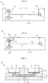
- the analytical tool A1 includes a body 1, an inlet reservoir 2, a filter 21, an outlet reservoir 3, a capillary tube 4, electrode contact elements 51 and 52, a secondary reservoir 6, a connection channel 7 and a flat member 81.
- Fig. 1 is a plan view of the analytical tool A1.
- Fig. 2 is a cross-sectional view taken along line II-II of Fig. 1.
- Fig. 3 is a cross-sectional view taken along line III-III of Fig. 1 .
- the body 1 is a base of the analytical tool A1 and made of a material that is not particularly limited. Examples of materials for the body 1 include glass, fused silica and plastic. In this embodiment, the body 1 includes an upper base 11 and a lower base 12 jointed together. Alternatively, the body 1 may be constructed of a single piece.
- the inlet reservoir 2 servers as an inlet for introducing a solution containing a sample.
- the inlet reservoir 2 is formed in the upper base 11 of the body 1.
- the sample-containing solution may be a diluted sample prepared by diluting a sample such as blood with a predetermined diluent. The dilution may be performed in another reservoir (not shown) of the analytical tool A1 or in the analytical device B, which will be described later.
- the filter 21 is disposed such that a solution introduced into the inlet reservoir 2 flows through for removing interfering substances, examples of which are listed below.
- the filter 21 is disposed on the bottom of the inlet reservoir 2.
- the filter 21 is not limited to any specific configuration as long as interfering substances can be appropriately removed.
- a cellulose acetate membrane filter (available from ADVANTEC, Type: Y100, Thickness: 95 ⁇ m) is one preferable example.
- the outlet reservoir 3 is disposed at a downstream end of an electroosmotic flow in capillary electrophoresis.
- the outlet reservoir 3 may be a through hole formed in the upper base 11 of the body 1.
- the capillary tube 4 connects the inlet reservoir 2 and the outlet reservoir 3, and an electroosmotic flow occurs through the capillary tube 4.
- the capillary tube 4 may be a groove formed in the lower base 12 of the body 1.
- the body 1 may have recesses or similar structure through which light can travel toward the capillary tube 4 and exit after passing through the capillary tube 4.
- the capillary tube 4 is not limited to any particular size and may, for example, be 25 to 100 ⁇ m in width, 25 to 100 ⁇ m in height or depth, and 5 to 150 mm in length.
- the overall size of the analytical tool A1 is determined depending on the size of the capillary tube 4 as well as the sizes and arrangements of the inlet reservoir 2, the outlet reservoir 3, the secondary reservoir 6, and so on.
- the electrode contact elements 51 and 52 are used for establishing electrical connection with the analytical device B. When electrical connection is established, a voltage is applied to the capillary tube 4 for causing electrophoresis.
- the electrode contact element 51 and the inlet reservoir 2 are on the same side of the capillary tube 4.
- the electrode contact element 52 and the outlet reservoir 3 are on the same side of the capillary tube 4.
- the electrode contact elements 51 and 52 are not limited to any specific configuration and can be any elements for establishing electrical connection to the analytical device B and applying a voltage to a liquid in the capillary tube 4. This embodiment is directed to an example in which the electrode contact elements 51 and 52 are metallic pipes disposed as channels.
- the channel of the electrode contact element 51 is in communication with the inlet reservoir 2, whereas the channel of the electrode contact element 52 is in communication with the outlet reservoir 3. Electrical connection is established when the electrodes (not shown) or other parts of the analytical device B are placed in contact with the outer surface of each metallic pipe, while a liquid is in contact with its inner surface of the pipe.
- the electrode contact elements 51 and 52 may be reservoirs for holding a liquid. In this case, electrical connection is established when the electrodes (not shown) or other parts of the analytical device B are put into the liquid.
- the secondary reservoir 6 has an enlarged portion 61 and is in communication with the inlet reservoir 2 and the capillary tube 4.
- the secondary reservoir 6 is formed in the upper base 11 of the body 1.
- the interior of the secondary reservoir 6 from the enlarged portion 61 to its top opening has a cross-sectional area that is substantially larger than the connection channel 7. Therefore, the enlarged portion 61 provides a sudden increase in the cross-sectional area of the flow passage.
- the "sudden increase" in the cross-sectional area of the flow passage refers to an increase such that a liquid surface at the enlarged portion 61 will have a surface tension which may affect migration of the liquid in the capillary tube 4 during a later-described analytical process.
- connection channel 7 provides a flow passage between the inlet reservoir 2 and the secondary reservoir 6.
- connection channel 7 is a groove formed in the upper base 11 of the body 1.
- the capillary tube 4 is connected to the connection channel 7 at a location between the inlet reservoir 2 and the outlet reservoir 3.
- the flat member 81 is an example of a pressure fluctuation reducer.
- the pressure fluctuation reducer serves to reduce pressure fluctuations in a liquid within the capillary tube 4 caused in the presence of surface tension of the liquid at the enlarged portion 61.
- the flat member 81 is a planer member disposed to have a thickness in a direction coinciding with the depth direction of the secondary reservoir 6.
- the flat member 81 is made of a resin having liquid impermeability.
- PET resin is PET resin.
- the flat member 81 is made of a PET film (available from FUJIMORI KOGYO, Type: TCP188, Thickness: 188 ⁇ m).
- the flat member 81 is placed in the secondary reservoir 6 so as to close the connection channel 7 but is not fixed or bonded to the secondary reservoir 6.
- the flat member 81 of this embodiment has a hydrophilic surface 812.
- the hydrophilic surface 812 is formed by treating a surface of the flat member 81 to be hydrophilic.
- the hydrophilic surface 812 faces the enlarged portion 61.
- the analytical device B performs analysis by electrophoresis, with the analytical tool A1 installed in the analytical device B.
- the analytical device B includes electrodes 91 and 92, a light emitting unit 931, a light receiving unit 932, an inlet nozzle 94, pressure nozzles 95 and 96, a pump 97, a controller 98, a diluent reservoir 991 and a buffer reservoir 992.
- Fig. 4 illustrates the components of the analytical device B only schematically.
- the electrodes 91 and 92 are used to apply a predetermined voltage across the capillary tube 4 for causing electrophoresis.
- the electrode 91 is brought into contact with the electrode contact element 51 of the analytical tool A1, and the electrode 92 with the electrode contact element 52 of the analytical tool A1 to apply a voltage.
- the magnitude of a voltage applied across the electrodes 91 and 92 is not particularly limited and may be within a range of 0.5 to 20 kV.
- the electrodes 91 and 92 are configured to be movable toward and away from the analytical tool A1 in a predetermined direction.
- the light emitting unit 931 emits light for measuring absorbance in electrophoresis analysis.
- the light emitting unit 931 includes a light-emitting element such as an LED chip for emitting light in a predetermined wavelength range, an optical filter and a lens.
- the optical filter passes certain wavelengths of light emitted from the light-emitting element, while attenuating other wavelengths.
- the lens is used to converge light having passed through the optical filter to a specific analysis point in the capillary tube 4 of the analytical tool A1.
- the light emitting unit 931 may be provided with one or more slits to remove undesirable components which may scatter, from light traveled through the optical filter and the lens.
- the light receiving unit 932 receives light traveled through the analysis point in the capillary tube 4 of the analytical tool A1 and includes, for example, a photodiode and a photo IC.
- the diluent reservoir 991 holds a diluent Ld used to dilute the sample to a concentration appropriate for the analysis.
- the diluent Ld contains an additional component (described later) for enabling removal interfering substances.
- the main component of the diluent Ld is not particularly limited and may be water or saline, for example.
- the main component of the diluent Ld is similar in composition to a buffer solution Lm, which will be described below.
- the diluent Ld contains, as the additional component mentioned above, an anionic group-containing compound added to the main component. Examples of anionic group-containing compounds include an anionic group-containing polysaccharide.
- the anionic group-containing polysaccharide may be at least one polysaccharide selected from the group consisting of sulfated polysaccharide, carboxylated polysaccharide, sulfonated polysaccharide and phosphorylated polysaccharide.
- the carboxylated polysaccharide is preferably alginic acid or a salt thereof (such as sodium alginate).
- the sulfated polysaccharide may be chondroitin sulfate. There are seven types of chondroitin sulfates A, B, C, D, E, H and K, and any of them may be used.
- the diluent Ld is prepared by adding chondroitin sulfate to the main component having the same composition as the buffer solution Lm.
- the anionic group-containing compound chondroitin sulfate
- the anionic group-containing compound is contained in a concentration of, for example, 0.01% to 5% by weight.
- the buffer reservoir 992 holds the buffer solution Lm.
- the buffer solution Lm is introduced into e.g., the capillary tube 4 to provide a site for capillary electrophoresis.
- the buffer solution Lm is not particularly limited, one containing an acid is preferable.
- acids include citric acid, maleic acid, tartaric acid, succinic acid, fumaric acid, phthalic acid, malonic acid and malic acid.
- the buffer solution Lm contains a weak base. Examples of weak bases include arginine, lysine, histidine and tris.
- the buffer solution Lm has a pH of 4.5 to 6.
- the buffer solution Lm may be any of MES, ADA, ACES, BES, MOPS, TES, HEPES, and so on.
- the buffer solution Lm contains an anionic group-containing compound, which is also contained in the diluent Ld.
- the anionic group-containing compound chondroitin sulfate
- the anionic group-containing compound is contained in a concentration of 0.01% to 5% by weight.
- reservoirs for holding the diluent Ld and the buffer solution Lm may be disposed in the analytical tool A1.
- a reservoir for mixing a sample such as blood with the diluent Ld may be disposed either in the analytical tool A1 or in the analytical device B.
- the inlet nozzle 94 is used to suck up the diluent Ld from the diluent reservoir 991, the buffer solution Lm from the buffer reservoir 992, and the diluted sample from the mixing reservoir (not shown) and introduce into appropriate parts of the analytical tool A1.
- the pressure nozzle 95 applies a predetermined pressure (negative or positive pressure) to the inlet reservoir 2 of the analytical tool A1 when placed in close proximity to the inlet reservoir 2.
- the pressure nozzle 96 applies a predetermined pressure (negative or positive pressure) to the outlet reservoir 3 of the analytical tool A1 when in when placed in close proximity to the outlet reservoir 3.
- the pump 97 is connected to the inlet nozzle 94, the pressure nozzle 95 and the pressure nozzle 96, and acts as a pressure source used to apply pressure to the inlet nozzle 94, the pressure nozzle 95 and the pressure nozzle 96.
- the pump 97 may be additionally connected to the pressure nozzle (not shown) for applying pressure from a location within the analytical tool A1, other than from the inlet nozzle 94, the pressure nozzle 95 and the pressure nozzle 96.
- the controller 98 controls the parts and units of the analytical device B.
- the controller 98 may include a CPU, memory and interface.
- the analytical process may include a sample collecting step, a buffer introducing step, a mixing step and an electrophoresis step.
- a sample is prepared.
- the sample is blood collected from a human body.
- the blood sample may be whole blood or blood after hemolysis.
- the buffer solution Lm is introduced into the capillary tube 4. More specifically, as shown in Fig. 5 , the buffer solution Lm is sucked from the buffer reservoir 992 into the inlet nozzle 94 and then introduced into the outlet reservoir 3. Then, pressure is appropriately applied to the outlet reservoir 3 by the pressure nozzle 96, causing the buffer solution Lm to flow into the capillary tube 4. Preferably, the buffer solution Lm also fills the electrode contact element 52.
- the sample is mixed with the diluent Ld.
- the sample is dropped into the mixing reservoir, which is included in the analytical device or the analytical tool A1.
- the diluent Ld is sucked from the diluent reservoir 991 into the inlet nozzle 94 and then introduced into the mixing reservoir.
- the sample is diluted with the diluent Ld to prepare a diluted sample Sm.
- one or more accessory ingredients i.e., components other than the analyte components
- chondroitin sulfate i.e., an example of the anionic group-containing compound
- the inventors have also identified lipids as specific examples of accessory ingredients that may form aggregates.
- the diluted sample Sm thus prepared is sucked into the inlet nozzle 94 and then introduced into the inlet reservoir 2 of the analytical tool A1. Then, pressure is applied to the inlet reservoir 2 by the pressure nozzle 95, causing the diluted sample Sm to flow into the connection channel 7 as shown in Figs. 6 and 7 .
- the diluted sample Sm passes through the filter 21 before flowing into the connection channel 7, so that aggregates of the accessory ingredients (such as lipids) and the anionic group-containing compound (chondroitin sulfate, in this embodiment) are removed by the filter 21 from the diluted sample Sm.
- the diluted sample Sm flows through the connection channel 7 to reach the secondary reservoir 6.
- the diluted sample Sm also fills the electrode contact element 51.
- the electrode 91 is brought into contact with the electrode contact element 51 and the electrode 92 with electrode contact element 52. Then, under control by the controller 98, a voltage of e.g., 0.5 to 20 kV is applied across the electrode contact elements 51 and 52 to induce an electroosmotic flow. As a result, the diluted sample Sm in the capillary tube 4 gradually moves with the electroosmotic flow.
- the light emitting unit 931 starts to emit light and the light receiving unit 932 measures the absorbance. Next, the absorbance is analyzed in relation to the time elapsed from the start of voltage application by the electrodes 91 and 92. Some components in the diluted sample Sm travel faster and thus exhibit an absorbance peak relatively short time after the start of voltage application.
- Some components in the diluted sample Sm travel slower and thus exhibit an absorbance peak relatively long time after the start of voltage application. This difference makes it possible to carry out analysis (separate measurement) of the individual components contained in the diluted sample Sm.
- the measured absorbance may be subjected to computation (such as differential or finite differences processing by the controller 98) to create an electropherogram. Calculating a peak height or a peak area in this electropherogram can determine the factors related to the diluted sample Sm, such as the component ratios.
- the sample (diluted sample Sm) is analyzed through the above steps.
- the flat member 81 At least in one of the mixing step and the electrophoresis step, there is a time at which the diluted sample Sm comes into contact with the flat member 81 as shown in Fig. 7 .
- the diluted sample Sm flowing through the connection channel 7 reaches the enlarged portion 61
- the diluted sample Sm comes into contact with the hydrophilic surface 812 of the flat member 81. Due to the hydrophilicity of the hydrophilic surface 812, the diluted sample Sm rapidly spreads over the entire hydrophilic surface 812.
- the flat member 81 is simply placed on the bottom of the secondary reservoir 6. Therefore, in response to a pressure for further pushing the diluted sample Sm into the secondary reservoir 6, the flat member 81 is slightly lifted upward as seen in the figure, allowing some of the diluted sample Sm to enter the secondary reservoir 6.
- the sample used in this embodiment was 1.5 ⁇ L of whole blood collected from a human body.
- the collected sample was diluted with 60 ⁇ L of the diluent Ld to prepare a diluted sample Sm.
- the diluent Ld was prepared by using 38 mM citric acid, 0.95% (w/v) chondroitin sulfate C-sodium, 475 mM of NDSB-201 (available from Anatrace), 19 mM of MES, 0.1% (w/v) of EMULGEN LS-110 (available from Kao Corporation), 0.02% (w/v) of sodium azide, and 0.025% (w/v) ProClinTM 950 (available from Sigma-Aldrich), followed by pH adjustment to pH 6.0 using dimethylaminoethanol (for pH adjustment).
- the buffer solution Lm was prepared by using 40 mM of citric acid, 1.25% (w/v) chondroitin sulfate C-sodium, 20 mM of piperazine, 0.1% (w/v) of EMULGEN LS-110 (available from Kao Corporation), 0.02% (w/v) of sodium azide, and 0.025% (w/v) ProClinTM 950 (available from Sigma-Aldrich), followed by pH adjustment to pH 5.0 using dimethylaminoethanol (for pH adjustment).
- the light receiving unit 932 measured the absorbance at 415 nm. The duration of electrophoresis was 35 seconds.
- the diluted sample Sm reaching the enlarged portion 61 comes into contact with the flat member 81, which acts as a pressure fluctuation reducer.
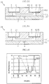
- the analytical tool X of a comparative example is discussed. As shown in Fig. 9 , the analytical tool X is not provided with the flat member 81. Therefore, a diluted sample Sm reaching the enlarged portion 61 will have a top surface assuming a shape that bulges upward into the secondary reservoir 6. This bulging shape of the diluted sample Sm tends to deform frequently depending, for example, on the pressure applied to the diluted sample Sm.
- the diluted sample Sm cannot freely flow back into the inlet reservoir 2 as the inlet reservoir 2 is closed by the filter 21 used to remove interfering substances from the diluted sample Sm.
- a change in the bulging shape of the diluted sample Sm at the enlarged portion 61 directly causes a pressure change across the diluted sample Sm.
- Such a pressure change may cause unintentional migration of the buffer solution Lm and the diluted sample Sm in the capillary tube 4.
- Such a pressure change is especially detrimental during the electrophoresis step because the analyte components in the diluted sample Sm may be induced to migrate independently of the migration by electrophoresis.
- the flat member 81 prevents the diluted sample Sm from assuming the bulging shape, which tends to be easily deformed due to various factors.
- This configuration is effective to inhibit unintentional migration of the buffer solution Lm and the diluted sample Sm in the capillary tube 4. This embodiment therefore ensures appropriate removable of interfering substances as well as more proper analysis.
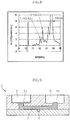
- Fig. 8 is a graph showing the analytical result obtained by the analytical process according to this embodiment.
- the horizontal axis represents the time of measurement, whereas the vertical axis represents the absorbance change rate.
- the graph of this embodiment shows clear peaks corresponding to the analyte components, namely L-HbA1c, S-HbA1c and HbA0.
- Figs. 10 and 11 are graphs showing the analytical result obtained by using the analytical tool X of the comparative example shown in Fig. 9 . More specifically, Fig. 10 shows the analytical result obtained by introducing the diluted sample Sm until it flows out of the secondary reservoir 6, whereas Fig.
- FIG. 11 shows the analytical result obtained by introducing the diluted sample Sm so as not to reach the opening of the secondary reservoir 6 or the enlarged portion 61.
- the graphs of the comparative examples show no clear peaks corresponding to the analyte components. The absence of clear peaks is due to unintentional migration of the buffer solution Lm and the diluted sample Sm in the capillary tube 4, and the unintentional migration is caused by the pressure fluctuations resulting from the surface tension of the diluted sample Sm.
- the flat member 81 is made from a resin impermeable to the diluted sample Sm and simply placed on the bottom of the secondary reservoir 6. Therefore, the flat member 81 prevents the diluted sample Sm from forming a bulging surface shape at the enlarged portion 61, while allowing the diluted sample Sm to flow into the secondary reservoir 6 in response to a pressure pushing the diluted sample Sm. This configuration is preferable to avoid excessive fluctuations of the pressure acting on the diluted sample Sm.
- the flat member 81 has the hydrophilic surface 812 facing the enlarged portion 61. Therefore, the diluted sample promptly spreads over the entire hydrophilic surface 812 upon reaching the enlarged portion 61. This configuration is effective to prevent the diluted sample Sm from forming a bulging surface shape by the action of surface tension.
- Figs. 12 to 24 show other embodiments of the present invention.
- elements identical or similar to those of the foregoing embodiment are designated by the same reference signs as those used for the foregoing embodiment.
- Fig. 12 shows an analytical tool according to Embodiment 2 of the present invention.
- the analytical tool A2 of this embodiment differs from the analytical tool A1 in that the flat member 81 does not have a hydrophilic surface 812 facing the enlarged portion 61.
- Fig. 13 is a graph showing the analytical result obtained by an analytical process using the analytical tool A2.
- the analytical process of this embodiment is performed under the same conditions as the analytical process performed using the analytical tool A1.
- the graph of this embodiment shows clear peaks corresponding to the analyte components, indicating that the flat member 81 of this embodiment is effective to substantially reduce pressure fluctuations caused by the surface tension.
- Fig. 14 shows an analytical tool according to Embodiment 3 of the present invention.
- the analytical tool A3 of this embodiment differs from the analytical tools A1 and A2 described above in that the flat member 81 has a portion 811 fixed to the secondary reservoir 6.
- the fixed portion 811 is a portion of the flat member 81 secured to the bottom of the secondary reservoir 6 by heat fusing or adhesive. This configuration enables the flat member 81 to act as a value.
- This embodiment is effective to substantially reduce pressure fluctuations caused by the surface tension of the diluted sample Sm at the enlarged portion 61.
- Fig. 15 shows an analytical tool according to Embodiment 4 of the present invention.
- the analytical tool A4 of this embodiment differs from the foregoing embodiments in that the flat member 81, as well as the filter 21, is made of a porous medium that allows a liquid to pass through. Specific examples of porous mediums usable for the flat member 81 are the same as those for the filter 21.
- the flat member 81 of this embodiment is placed on the bottom of the secondary reservoir 6 without being fixed.
- Fig. 16 is a graph showing the analytical result obtained by an analytical process using the analytical tool A4.
- the analytical process of Embodiment 2 is performed under the same conditions as the analytical process performed using the analytical tool A1.
- the graph of this embodiment shows clear peaks corresponding to the analyte components, indicating that the flat member 81 made of a porous medium is effective to substantially reduce pressure fluctuations caused by the surface tension.
- Fig. 17 shows an analytical tool according to Embodiment 5 of the present invention.
- the analytical tool A5 of the present invention is similar to the analytical tool A4 in that the flat member 81 is made of the same porous medium as the filter 21.
- the difference lies in that the flat member 81 of this embodiment has a portion 811 fixed to the bottom of the secondary reservoir 6.
- the fixed portion 811 may extend along the entire outer edge of the flat member 81 and still allows a liquid to pass through owing to the flat member 81 being porous.
- Fig. 18 is a graph showing the analytical result obtained by an analytical process using the analytical tool A5.
- the analytical process of Embodiment 5 is performed under the same conditions as the analytical process performed using the analytical tool A1.
- the graph of this embodiment shows clear peaks corresponding to the analyte components, indicating that the porous flat member 81 having the fixed portion 811 is effective to substantially reduce pressure fluctuations caused by the surface tension.
- Fig. 19 shows an analytical tool according to Embodiment 6 of the present invention.
- the analytical tool A6 of this embodiment differs in that the enlarged portion 61 has an inner surface that includes a hydrophilic region 82.
- the hydrophilic region 82 is an inner surface area of the enlarged portion 61 treated to be hydrophilic.
- This embodiment having such a configuration ensures that the diluted sample Sm reaching the enlarged portion 61 promptly spreads over the hydrophilic region 82. Consequently, the diluted sample Sm does not form a bulging shape on the top surface reaching the enlarged portion 61.
- This embodiment is effective to substantially reduce pressure fluctuations caused by the surface tension of the diluted sample Sm.
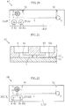
- Figs. 20 and 21 each show an analytical tool according to Embodiment 7 of the present invention.
- the analytical tool A7 additionally includes an open reservoir 83, which is one example of the pressure fluctuation reducer.
- the open reservoir 83 is a separate reservoir from the secondary reservoir 6 and is in communication with the secondary reservoir 6 through the connection channel 7.
- the open reservoir 83 is open at the top as shown in Fig. 21 .
- the open reservoir 83 shown in Figs. 20 and 21 is similar in shape to the secondary reservoir 6 and has an enlarged portion 831.
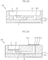
- Figs. 22 and 23 each show an analytical tool according to Embodiment 8 of the present invention.
- the analytical tool A8 of this embodiment has an open reservoir 83 that is continuous with the secondary reservoir 6.
- the secondary reservoir 6 and the open reservoir 83 together form one reservoir that is open at the top as seen in Fig. 23 . This configuration ensures appropriate removable of interfering substances as well as more reliable analysis.
- Fig. 24 shows an analytical tool according to Embodiment 9 of the present invention.
- the analytical tool A9 of this embodiment differs from the foregoing embodiments in that the secondary reservoir 6 is not provided.
- the enlarged portion 61 of this embodiment corresponds to where the connection channel 7 opens in the outer surface of the body 1.
- the analytical tool A9 has a flat member 81 that is one example of the pressure fluctuation reducer.
- This flat member 81 has a portion 811 is fixed to the enlarged portion 61.
- this flat member 81, as well as e.g., the filter 21, is made of a porous medium allowing a liquid to pass through.
- the pressure fluctuation reducer of this embodiment may be combined with any configuration described in the foregoing embodiments. This embodiment ensures appropriate removable of interfering substances as well as more reliable analysis.
- the analytical tool and the analytical system according to the present invention are not limited to the foregoing embodiments. Various design changes can be made to the specific configurations of the constituent parts of the analytical tool and the analytical system according to the present invention.
Landscapes
- Health & Medical Sciences (AREA)
- Life Sciences & Earth Sciences (AREA)
- Chemical & Material Sciences (AREA)
- Engineering & Computer Science (AREA)
- Biomedical Technology (AREA)
- Physics & Mathematics (AREA)
- Analytical Chemistry (AREA)
- General Health & Medical Sciences (AREA)
- Hematology (AREA)
- Molecular Biology (AREA)
- Pathology (AREA)
- General Physics & Mathematics (AREA)
- Biochemistry (AREA)
- Immunology (AREA)
- Chemical Kinetics & Catalysis (AREA)
- Dispersion Chemistry (AREA)
- Biophysics (AREA)
- Urology & Nephrology (AREA)
- Food Science & Technology (AREA)
- Medicinal Chemistry (AREA)
- Clinical Laboratory Science (AREA)
- Electrochemistry (AREA)
- Ecology (AREA)
- Automatic Analysis And Handling Materials Therefor (AREA)
- Sampling And Sample Adjustment (AREA)
Abstract
Description
- The present invention relates to analytical tools and analytical systems.
- The degrees of glycation of various proteins have been analyzed and used as indicators showing the state of a living body. Among such indicators, the glycation degree of hemoglobin (Hb) in general, and of stable HbA1c (hereinafter, may be referred to simply as "s-HbA1c") in particular, reflects the past history of the blood glucose level in a living body and thus serves as an important indicator in, for example, the diagnosis and treatment of diabetes. HbA1c is defined as HbA (α2β2) glycated at the N-terminal valine of the β chain.
- Electrophoresis is used as an analytical technique for Hb, particularly for s-HbA1c. For example,
JP-A-2006-145537 JP-A-H9-510792 WO 2010/010859 ,JP-A-2009-109230 WO 2008/136321 andWO 2008/136465 teach adding an additional component to a buffer solution with the aim of optimizing analysis and improving the accuracy. Specifically,JP-A-2009-109230 WO 2008/136321 teach chondroitin sulfate as an example of an additional component of the buffer solution. In addition,WO 2008/136465 describes an analytical process involving supplying a sample continuously during electrophoretic separation of the sample. Such a method facilitates an electrophoresis chip used in the method to be more compact. - A typical sample to be analyzed is blood, which is a biological sample. Naturally, blood collected as a sample from a patient may have various properties depending on the patient's conditions, including the disease state and the physical make-up. In addition, the additional components and/or analytical processes cited above may result in creation of substances potentially interfering with proper analysis but not much has been revealed. The same applies to analysis on samples other than blood. To improve the accuracy of analysis, removing such interfering substances is preferable. However, removal of such interfering substances may affect the electrophoresis in a capillary tube.
- In view of the circumstances described above, the present invention aims to provide an analytical tool and an analytical system capable of performing proper analysis.
- According to a first aspect of the present invention, there is provided an analytical tool for analysis of a sample by capillary electrophoresis. In an embodiment, the analytical tool is provided with: an inlet reservoir into which a sample is introduced; a capillary tube in communication with the inlet reservoir; a filter through which a liquid from the inlet reservoir passes; an enlarged portion undergoing a sudden increase in a cross-sectional area and being in communication with the inlet reservoir and the capillary tube; and a pressure fluctuation reducer for preventing pressure fluctuation at the enlarge portion from affecting a liquid in the capillary tube.
- Preferably, the analytical tool may further include a secondary reservoir provided with the enlarged portion.
- Preferably, the analytical tool may further include a connection channel connecting the inlet reservoir to the enlarged portion, where the capillary tube is in communication with the connection channel at a location between the inlet reservoir and the enlarged portion.
- Preferably, the pressure fluctuation reducer may include a flat member covering at least a part of the enlarged portion and allowing gas flow.
- Preferably, the pressure fluctuation reducer may have a portion fixed to the enlarged portion.
- Preferably, the pressure fluctuation reducer may be made of a liquid-impermeable resin.
- Preferably, the flat member may have a hydrophilic surface facing the enlarged portion.
- Preferably, the pressure fluctuation reducer may be made of a liquid-permeable porous material.
- Preferably, the pressure fluctuation reducer may include a hydrophilic region formed by an inner surface region of the enlarged portion treated to be hydrophilic.
- Preferably, the pressure fluctuation reducer may include an open reservoir that is in communication with the secondary reservoir through the connection channel.
- Preferably, the secondary reservoir may be separated from the open reservoir.
- Preferably, the secondary reservoir may be continuous with the open reservoir.
- Preferably, the analytical tool may be configured as a disposable tool.
- According to a second aspect of the present invention, there is provided an analytical system that includes: an analytical tool noted above; and an analyzing unit into which the analytical tool is installed and configured to perform analysis by capillary electrophoresis in the capillary tube.
- According to the present invention, the pressure fluctuation reducer ensures that the liquid reaching the enlarged portion will not have surface tension which would cause pressure fluctuations in the capillary tube. As a result, unintentional migration of the liquid in the capillary tube is prevented. The analytical tool and system of the present invention are capable of removing interfering substances and yet capable of more stable analysis.
- Other features and advantages of the present invention will become more apparent from the detailed description given below with reference to the accompanying drawings.
-
-
Fig. 1 is a plan view of an analytical tool according toEmbodiment 1 of the present invention. -
Fig. 2 is a cross-sectional view taken along line II-II ofFig. 1 . -
Fig. 3 is a cross-sectional view taken along line III-III ofFig. 1 . -
Fig. 4 is a block diagram showing an analytical system according toEmbodiment 1 of the present invention. -
Fig. 5 is a plan view illustrating an analytical process using the analytical tool shown inFig. 1 . -
Fig. 6 is a plan view illustrating the analytical process using the analytical tool shown inFig. 1 . -
Fig. 7 is a cross-sectional view taken along line VII-VII ofFig. 6 . -
Fig. 8 is a graph showing exemplary analytical result obtained by the analytical process using the analytical tool shown inFig. 1 . -
Fig. 9 is a cross-sectional view illustrating an analytical process using an analytical tool of a comparative example. -
Fig. 10 is a graph showing exemplary analytical result obtained by the analytical process using the analytical tool of the comparative example. -
Fig. 11 is a graph showing exemplary analytical result obtained by another analytical process using the analytical tool of the comparative example. -
Fig. 12 is a cross-sectional view showing an analytical tool according toEmbodiment 2 of the present invention. -
Fig. 13 is a graph showing exemplary analytical result obtained by an analytical process using the analytical tool shown inFig. 12 . -
Fig. 14 is a cross-sectional view showing an analytical tool according toEmbodiment 3 of the present invention. -
Fig. 15 is a cross-sectional view showing an analytical tool according toEmbodiment 4 of the present invention. -
Fig. 16 is a graph showing exemplary analytical result obtained by an analytical process using the analytical tool shown inFig. 15 . -
Fig. 17 is a cross-sectional view showing an analytical tool according toEmbodiment 5 of the present invention. -
Fig. 18 is a graph showing exemplary analytical result obtained by an analytical process using the analytical tool shown inFig. 17 . -
Fig. 19 is a cross-sectional view showing an analytical tool according toEmbodiment 6 of the present invention. -
Fig. 20 is a cross-sectional view showing an analytical tool according toEmbodiment 7 of the present invention. -
Fig. 21 is a cross-sectional view taken along line XXI-XXI ofFig. 20 . -
Fig. 22 is a plan view showing an analytical tool according toEmbodiment 8 of the present invention. -
Fig. 23 is a cross-sectional view taken along line XXIII-XXIII ofFig. 22 . -
Fig. 24 is a cross-sectional view showing an analytical tool according to Embodiment 9 of the present invention. - Preferred embodiments of the present invention will now be specifically described with reference to the accompanying drawings.
-
Figs. 1 to 3 show an analytical tool according toEmbodiment 1 of the present invention.Fig. 4 shows an analytical system according toEmbodiment 1 of the present invention. An analytical system C of this embodiment includes an analytical device B and an analytical tool A1. The analytical system C performs an analytical process on a sample by using electrophoresis. Samples to be analyzed are not particularly limited. In this embodiment, the samples are blood collected from human subjects. Among the components of a sample, those targeted for analysis are defined as analyte components. - Examples of the analyte components include hemoglobin (Hb), albumin (Alb), globulin (α1, α2, β, and γ globulins) and fibrinogen. Examples of hemoglobin include normal hemoglobin (HbA0), glycated hemoglobin, modified hemoglobin and fetal hemoglobin (HbF). Examples of glycated hemoglobin include hemoglobin A1a (HbA1a), hemoglobin A1b (HbA1b), hemoglobin A1c (HbA1c) and GHbLys. Examples of hemoglobin A1c include stable HbA1c (s-HbA1c) and unstable HbAlc. Examples of modified hemoglobin include carbamylated Hb and acetylated Hb.
- The analytical tool A1 is installed into the analytical device B to provide a site for analysis. In this embodiment, the analytical tool A1 is a disposable analytical chip, which is designed to be used once or a limited number of times and then disposed. As shown in
Figs. 1 to 3 , the analytical tool A1 includes abody 1, aninlet reservoir 2, afilter 21, anoutlet reservoir 3, acapillary tube 4,electrode contact elements secondary reservoir 6, aconnection channel 7 and aflat member 81.Fig. 1 is a plan view of the analytical tool A1.Fig. 2 is a cross-sectional view taken along line II-II ofFig. 1. Fig. 3 is a cross-sectional view taken along line III-III ofFig. 1 . - The
body 1 is a base of the analytical tool A1 and made of a material that is not particularly limited. Examples of materials for thebody 1 include glass, fused silica and plastic. In this embodiment, thebody 1 includes anupper base 11 and alower base 12 jointed together. Alternatively, thebody 1 may be constructed of a single piece. - The
inlet reservoir 2 servers as an inlet for introducing a solution containing a sample. In this embodiment, theinlet reservoir 2 is formed in theupper base 11 of thebody 1. In one example, the sample-containing solution may be a diluted sample prepared by diluting a sample such as blood with a predetermined diluent. The dilution may be performed in another reservoir (not shown) of the analytical tool A1 or in the analytical device B, which will be described later. - The
filter 21 is disposed such that a solution introduced into theinlet reservoir 2 flows through for removing interfering substances, examples of which are listed below. In this embodiment, thefilter 21 is disposed on the bottom of theinlet reservoir 2. Thefilter 21 is not limited to any specific configuration as long as interfering substances can be appropriately removed. A cellulose acetate membrane filter (available from ADVANTEC, Type: Y100, Thickness: 95 µm) is one preferable example. - The
outlet reservoir 3 is disposed at a downstream end of an electroosmotic flow in capillary electrophoresis. Theoutlet reservoir 3 may be a through hole formed in theupper base 11 of thebody 1. - The
capillary tube 4 connects theinlet reservoir 2 and theoutlet reservoir 3, and an electroosmotic flow occurs through thecapillary tube 4. Thecapillary tube 4 may be a groove formed in thelower base 12 of thebody 1. Thebody 1 may have recesses or similar structure through which light can travel toward thecapillary tube 4 and exit after passing through thecapillary tube 4. Thecapillary tube 4 is not limited to any particular size and may, for example, be 25 to 100 µm in width, 25 to 100 µm in height or depth, and 5 to 150 mm in length. The overall size of the analytical tool A1 is determined depending on the size of thecapillary tube 4 as well as the sizes and arrangements of theinlet reservoir 2, theoutlet reservoir 3, thesecondary reservoir 6, and so on. - The
electrode contact elements capillary tube 4 for causing electrophoresis. Theelectrode contact element 51 and theinlet reservoir 2 are on the same side of thecapillary tube 4. Theelectrode contact element 52 and theoutlet reservoir 3 are on the same side of thecapillary tube 4. Theelectrode contact elements capillary tube 4. This embodiment is directed to an example in which theelectrode contact elements electrode contact element 51 is in communication with theinlet reservoir 2, whereas the channel of theelectrode contact element 52 is in communication with theoutlet reservoir 3. Electrical connection is established when the electrodes (not shown) or other parts of the analytical device B are placed in contact with the outer surface of each metallic pipe, while a liquid is in contact with its inner surface of the pipe. In an alternative example, theelectrode contact elements - The
secondary reservoir 6 has anenlarged portion 61 and is in communication with theinlet reservoir 2 and thecapillary tube 4. In this embodiment, thesecondary reservoir 6 is formed in theupper base 11 of thebody 1. The interior of thesecondary reservoir 6 from theenlarged portion 61 to its top opening has a cross-sectional area that is substantially larger than theconnection channel 7. Therefore, theenlarged portion 61 provides a sudden increase in the cross-sectional area of the flow passage. Note that the "sudden increase" in the cross-sectional area of the flow passage refers to an increase such that a liquid surface at theenlarged portion 61 will have a surface tension which may affect migration of the liquid in thecapillary tube 4 during a later-described analytical process. - The
connection channel 7 provides a flow passage between theinlet reservoir 2 and thesecondary reservoir 6. In this embodiment, theconnection channel 7 is a groove formed in theupper base 11 of thebody 1. Thecapillary tube 4 is connected to theconnection channel 7 at a location between theinlet reservoir 2 and theoutlet reservoir 3. - The
flat member 81 is an example of a pressure fluctuation reducer. The pressure fluctuation reducer serves to reduce pressure fluctuations in a liquid within thecapillary tube 4 caused in the presence of surface tension of the liquid at theenlarged portion 61. In this embodiment, theflat member 81 is a planer member disposed to have a thickness in a direction coinciding with the depth direction of thesecondary reservoir 6. In this embodiment, theflat member 81 is made of a resin having liquid impermeability. One example of such a resin is PET resin. In this embodiment, theflat member 81 is made of a PET film (available from FUJIMORI KOGYO, Type: TCP188, Thickness: 188 µm). In this embodiment, theflat member 81 is placed in thesecondary reservoir 6 so as to close theconnection channel 7 but is not fixed or bonded to thesecondary reservoir 6. - In addition, the
flat member 81 of this embodiment has ahydrophilic surface 812. Thehydrophilic surface 812 is formed by treating a surface of theflat member 81 to be hydrophilic. Thehydrophilic surface 812 faces theenlarged portion 61. - The analytical device B performs analysis by electrophoresis, with the analytical tool A1 installed in the analytical device B. The analytical device B includes
electrodes 91 and 92, alight emitting unit 931, alight receiving unit 932, aninlet nozzle 94,pressure nozzles pump 97, acontroller 98, adiluent reservoir 991 and abuffer reservoir 992. For convenience,Fig. 4 illustrates the components of the analytical device B only schematically. - The
electrodes 91 and 92 are used to apply a predetermined voltage across thecapillary tube 4 for causing electrophoresis. In this embodiment, theelectrode 91 is brought into contact with theelectrode contact element 51 of the analytical tool A1, and the electrode 92 with theelectrode contact element 52 of the analytical tool A1 to apply a voltage. The magnitude of a voltage applied across theelectrodes 91 and 92 is not particularly limited and may be within a range of 0.5 to 20 kV. In one example, theelectrodes 91 and 92 are configured to be movable toward and away from the analytical tool A1 in a predetermined direction. - The
light emitting unit 931 emits light for measuring absorbance in electrophoresis analysis. Thelight emitting unit 931 includes a light-emitting element such as an LED chip for emitting light in a predetermined wavelength range, an optical filter and a lens. The optical filter passes certain wavelengths of light emitted from the light-emitting element, while attenuating other wavelengths. The lens is used to converge light having passed through the optical filter to a specific analysis point in thecapillary tube 4 of the analytical tool A1. Thelight emitting unit 931 may be provided with one or more slits to remove undesirable components which may scatter, from light traveled through the optical filter and the lens. - The
light receiving unit 932 receives light traveled through the analysis point in thecapillary tube 4 of the analytical tool A1 and includes, for example, a photodiode and a photo IC. - The
diluent reservoir 991 holds a diluent Ld used to dilute the sample to a concentration appropriate for the analysis. In this embodiment, the diluent Ld contains an additional component (described later) for enabling removal interfering substances. The main component of the diluent Ld is not particularly limited and may be water or saline, for example. Preferably, the main component of the diluent Ld is similar in composition to a buffer solution Lm, which will be described below. The diluent Ld contains, as the additional component mentioned above, an anionic group-containing compound added to the main component. Examples of anionic group-containing compounds include an anionic group-containing polysaccharide. The anionic group-containing polysaccharide may be at least one polysaccharide selected from the group consisting of sulfated polysaccharide, carboxylated polysaccharide, sulfonated polysaccharide and phosphorylated polysaccharide. The carboxylated polysaccharide is preferably alginic acid or a salt thereof (such as sodium alginate). The sulfated polysaccharide may be chondroitin sulfate. There are seven types of chondroitin sulfates A, B, C, D, E, H and K, and any of them may be used. In the flowing description, the diluent Ld is prepared by adding chondroitin sulfate to the main component having the same composition as the buffer solution Lm. In one example, the anionic group-containing compound (chondroitin sulfate) is contained in a concentration of, for example, 0.01% to 5% by weight. - The
buffer reservoir 992 holds the buffer solution Lm. The buffer solution Lm is introduced into e.g., thecapillary tube 4 to provide a site for capillary electrophoresis. Although the buffer solution Lm is not particularly limited, one containing an acid is preferable. Examples of acids include citric acid, maleic acid, tartaric acid, succinic acid, fumaric acid, phthalic acid, malonic acid and malic acid. Preferably, the buffer solution Lm contains a weak base. Examples of weak bases include arginine, lysine, histidine and tris. In one example, the buffer solution Lm has a pH of 4.5 to 6. The buffer solution Lm may be any of MES, ADA, ACES, BES, MOPS, TES, HEPES, and so on. The buffer solution Lm contains an anionic group-containing compound, which is also contained in the diluent Ld. In one example, the anionic group-containing compound (chondroitin sulfate) is contained in a concentration of 0.01% to 5% by weight. - In the analytical system according to the present invention, reservoirs for holding the diluent Ld and the buffer solution Lm may be disposed in the analytical tool A1. In addition, a reservoir for mixing a sample such as blood with the diluent Ld may be disposed either in the analytical tool A1 or in the analytical device B.
- The
inlet nozzle 94 is used to suck up the diluent Ld from thediluent reservoir 991, the buffer solution Lm from thebuffer reservoir 992, and the diluted sample from the mixing reservoir (not shown) and introduce into appropriate parts of the analytical tool A1. - The
pressure nozzle 95 applies a predetermined pressure (negative or positive pressure) to theinlet reservoir 2 of the analytical tool A1 when placed in close proximity to theinlet reservoir 2. Thepressure nozzle 96 applies a predetermined pressure (negative or positive pressure) to theoutlet reservoir 3 of the analytical tool A1 when in when placed in close proximity to theoutlet reservoir 3. - The
pump 97 is connected to theinlet nozzle 94, thepressure nozzle 95 and thepressure nozzle 96, and acts as a pressure source used to apply pressure to theinlet nozzle 94, thepressure nozzle 95 and thepressure nozzle 96. Thepump 97 may be additionally connected to the pressure nozzle (not shown) for applying pressure from a location within the analytical tool A1, other than from theinlet nozzle 94, thepressure nozzle 95 and thepressure nozzle 96. - The
controller 98 controls the parts and units of the analytical device B. Thecontroller 98 may include a CPU, memory and interface. - The following now describes an analytical process performed using the analytical system C (analytical tool A1). The analytical process may include a sample collecting step, a buffer introducing step, a mixing step and an electrophoresis step.
- First, a sample is prepared. In this embodiment, the sample is blood collected from a human body. The blood sample may be whole blood or blood after hemolysis.
- Subsequently, the buffer solution Lm is introduced into the
capillary tube 4. More specifically, as shown inFig. 5 , the buffer solution Lm is sucked from thebuffer reservoir 992 into theinlet nozzle 94 and then introduced into theoutlet reservoir 3. Then, pressure is appropriately applied to theoutlet reservoir 3 by thepressure nozzle 96, causing the buffer solution Lm to flow into thecapillary tube 4. Preferably, the buffer solution Lm also fills theelectrode contact element 52. - Subsequently, the sample is mixed with the diluent Ld. For example, the sample is dropped into the mixing reservoir, which is included in the analytical device or the analytical tool A1. The diluent Ld is sucked from the
diluent reservoir 991 into theinlet nozzle 94 and then introduced into the mixing reservoir. As a result, the sample is diluted with the diluent Ld to prepare a diluted sample Sm. Note that experimental work by the inventors has found that one or more accessory ingredients (i.e., components other than the analyte components) of the blood sample may form aggregates with chondroitin sulfate (i.e., an example of the anionic group-containing compound) in the mixing step. The inventors have also identified lipids as specific examples of accessory ingredients that may form aggregates. The diluted sample Sm thus prepared is sucked into theinlet nozzle 94 and then introduced into theinlet reservoir 2 of the analytical tool A1. Then, pressure is applied to theinlet reservoir 2 by thepressure nozzle 95, causing the diluted sample Sm to flow into theconnection channel 7 as shown inFigs. 6 and 7 . The diluted sample Sm passes through thefilter 21 before flowing into theconnection channel 7, so that aggregates of the accessory ingredients (such as lipids) and the anionic group-containing compound (chondroitin sulfate, in this embodiment) are removed by thefilter 21 from the diluted sample Sm. The diluted sample Sm flows through theconnection channel 7 to reach thesecondary reservoir 6. Preferably, the diluted sample Sm also fills theelectrode contact element 51. - Subsequently, the
electrode 91 is brought into contact with theelectrode contact element 51 and the electrode 92 withelectrode contact element 52. Then, under control by thecontroller 98, a voltage of e.g., 0.5 to 20 kV is applied across theelectrode contact elements capillary tube 4 gradually moves with the electroosmotic flow. Thelight emitting unit 931 starts to emit light and thelight receiving unit 932 measures the absorbance. Next, the absorbance is analyzed in relation to the time elapsed from the start of voltage application by theelectrodes 91 and 92. Some components in the diluted sample Sm travel faster and thus exhibit an absorbance peak relatively short time after the start of voltage application. Some components in the diluted sample Sm travel slower and thus exhibit an absorbance peak relatively long time after the start of voltage application. This difference makes it possible to carry out analysis (separate measurement) of the individual components contained in the diluted sample Sm. The measured absorbance may be subjected to computation (such as differential or finite differences processing by the controller 98) to create an electropherogram. Calculating a peak height or a peak area in this electropherogram can determine the factors related to the diluted sample Sm, such as the component ratios. The sample (diluted sample Sm) is analyzed through the above steps. - At least in one of the mixing step and the electrophoresis step, there is a time at which the diluted sample Sm comes into contact with the
flat member 81 as shown inFig. 7 . In this embodiment, when the diluted sample Sm flowing through theconnection channel 7 reaches theenlarged portion 61, the diluted sample Sm comes into contact with thehydrophilic surface 812 of theflat member 81. Due to the hydrophilicity of thehydrophilic surface 812, the diluted sample Sm rapidly spreads over the entirehydrophilic surface 812. As mentioned above, theflat member 81 is simply placed on the bottom of thesecondary reservoir 6. Therefore, in response to a pressure for further pushing the diluted sample Sm into thesecondary reservoir 6, theflat member 81 is slightly lifted upward as seen in the figure, allowing some of the diluted sample Sm to enter thesecondary reservoir 6. - In a specific analysis performed according to the present embodiment, the sample used in this embodiment was 1.5 µL of whole blood collected from a human body. The collected sample was diluted with 60 µL of the diluent Ld to prepare a diluted sample Sm. The diluent Ld was prepared by using 38 mM citric acid, 0.95% (w/v) chondroitin sulfate C-sodium, 475 mM of NDSB-201 (available from Anatrace), 19 mM of MES, 0.1% (w/v) of EMULGEN LS-110 (available from Kao Corporation), 0.02% (w/v) of sodium azide, and 0.025% (w/v) ProClin™ 950 (available from Sigma-Aldrich), followed by pH adjustment to pH 6.0 using dimethylaminoethanol (for pH adjustment). The buffer solution Lm was prepared by using 40 mM of citric acid, 1.25% (w/v) chondroitin sulfate C-sodium, 20 mM of piperazine, 0.1% (w/v) of EMULGEN LS-110 (available from Kao Corporation), 0.02% (w/v) of sodium azide, and 0.025% (w/v) ProClin™ 950 (available from Sigma-Aldrich), followed by pH adjustment to pH 5.0 using dimethylaminoethanol (for pH adjustment). The
light receiving unit 932 measured the absorbance at 415 nm. The duration of electrophoresis was 35 seconds. - The following now describes the operations of the analytical tool A1 and the analytical system C.
- According to this embodiment, the diluted sample Sm reaching the
enlarged portion 61 comes into contact with theflat member 81, which acts as a pressure fluctuation reducer. For the purpose comparison, an analytical tool X of a comparative example is discussed. As shown inFig. 9 , the analytical tool X is not provided with theflat member 81. Therefore, a diluted sample Sm reaching theenlarged portion 61 will have a top surface assuming a shape that bulges upward into thesecondary reservoir 6. This bulging shape of the diluted sample Sm tends to deform frequently depending, for example, on the pressure applied to the diluted sample Sm. In addition, the diluted sample Sm cannot freely flow back into theinlet reservoir 2 as theinlet reservoir 2 is closed by thefilter 21 used to remove interfering substances from the diluted sample Sm. Thus, a change in the bulging shape of the diluted sample Sm at theenlarged portion 61 directly causes a pressure change across the diluted sample Sm. Such a pressure change may cause unintentional migration of the buffer solution Lm and the diluted sample Sm in thecapillary tube 4. Such a pressure change is especially detrimental during the electrophoresis step because the analyte components in the diluted sample Sm may be induced to migrate independently of the migration by electrophoresis. In this embodiment, however, theflat member 81 prevents the diluted sample Sm from assuming the bulging shape, which tends to be easily deformed due to various factors. This configuration is effective to inhibit unintentional migration of the buffer solution Lm and the diluted sample Sm in thecapillary tube 4. This embodiment therefore ensures appropriate removable of interfering substances as well as more proper analysis. -
Fig. 8 is a graph showing the analytical result obtained by the analytical process according to this embodiment. The horizontal axis represents the time of measurement, whereas the vertical axis represents the absorbance change rate. As can be seen, the graph of this embodiment shows clear peaks corresponding to the analyte components, namely L-HbA1c, S-HbA1c and HbA0.Figs. 10 and 11 are graphs showing the analytical result obtained by using the analytical tool X of the comparative example shown inFig. 9 . More specifically,Fig. 10 shows the analytical result obtained by introducing the diluted sample Sm until it flows out of thesecondary reservoir 6, whereasFig. 11 shows the analytical result obtained by introducing the diluted sample Sm so as not to reach the opening of thesecondary reservoir 6 or theenlarged portion 61. Unlike the graph ofFig. 8 , the graphs of the comparative examples show no clear peaks corresponding to the analyte components. The absence of clear peaks is due to unintentional migration of the buffer solution Lm and the diluted sample Sm in thecapillary tube 4, and the unintentional migration is caused by the pressure fluctuations resulting from the surface tension of the diluted sample Sm. - The
flat member 81 is made from a resin impermeable to the diluted sample Sm and simply placed on the bottom of thesecondary reservoir 6. Therefore, theflat member 81 prevents the diluted sample Sm from forming a bulging surface shape at theenlarged portion 61, while allowing the diluted sample Sm to flow into thesecondary reservoir 6 in response to a pressure pushing the diluted sample Sm. This configuration is preferable to avoid excessive fluctuations of the pressure acting on the diluted sample Sm. - In addition, the
flat member 81 has thehydrophilic surface 812 facing theenlarged portion 61. Therefore, the diluted sample promptly spreads over the entirehydrophilic surface 812 upon reaching theenlarged portion 61. This configuration is effective to prevent the diluted sample Sm from forming a bulging surface shape by the action of surface tension. -
Figs. 12 to 24 show other embodiments of the present invention. In these figures, elements identical or similar to those of the foregoing embodiment are designated by the same reference signs as those used for the foregoing embodiment. -
Fig. 12 shows an analytical tool according toEmbodiment 2 of the present invention. The analytical tool A2 of this embodiment differs from the analytical tool A1 in that theflat member 81 does not have ahydrophilic surface 812 facing theenlarged portion 61.Fig. 13 is a graph showing the analytical result obtained by an analytical process using the analytical tool A2. Other than the configuration of theflat member 81, the analytical process of this embodiment is performed under the same conditions as the analytical process performed using the analytical tool A1. The graph of this embodiment shows clear peaks corresponding to the analyte components, indicating that theflat member 81 of this embodiment is effective to substantially reduce pressure fluctuations caused by the surface tension. -
Fig. 14 shows an analytical tool according toEmbodiment 3 of the present invention. The analytical tool A3 of this embodiment differs from the analytical tools A1 and A2 described above in that theflat member 81 has aportion 811 fixed to thesecondary reservoir 6. The fixedportion 811 is a portion of theflat member 81 secured to the bottom of thesecondary reservoir 6 by heat fusing or adhesive. This configuration enables theflat member 81 to act as a value. This embodiment is effective to substantially reduce pressure fluctuations caused by the surface tension of the diluted sample Sm at theenlarged portion 61. -
Fig. 15 shows an analytical tool according toEmbodiment 4 of the present invention. The analytical tool A4 of this embodiment differs from the foregoing embodiments in that theflat member 81, as well as thefilter 21, is made of a porous medium that allows a liquid to pass through. Specific examples of porous mediums usable for theflat member 81 are the same as those for thefilter 21. Theflat member 81 of this embodiment is placed on the bottom of thesecondary reservoir 6 without being fixed. -
Fig. 16 is a graph showing the analytical result obtained by an analytical process using the analytical tool A4. Other than the configuration of theflat member 81, the analytical process ofEmbodiment 2 is performed under the same conditions as the analytical process performed using the analytical tool A1. The graph of this embodiment shows clear peaks corresponding to the analyte components, indicating that theflat member 81 made of a porous medium is effective to substantially reduce pressure fluctuations caused by the surface tension. -
Fig. 17 shows an analytical tool according toEmbodiment 5 of the present invention. The analytical tool A5 of the present invention is similar to the analytical tool A4 in that theflat member 81 is made of the same porous medium as thefilter 21. The difference lies in that theflat member 81 of this embodiment has aportion 811 fixed to the bottom of thesecondary reservoir 6. In this embodiment, the fixedportion 811 may extend along the entire outer edge of theflat member 81 and still allows a liquid to pass through owing to theflat member 81 being porous. -
Fig. 18 is a graph showing the analytical result obtained by an analytical process using the analytical tool A5. Other than the configuration of theflat member 81, the analytical process ofEmbodiment 5 is performed under the same conditions as the analytical process performed using the analytical tool A1. The graph of this embodiment shows clear peaks corresponding to the analyte components, indicating that the porousflat member 81 having the fixedportion 811 is effective to substantially reduce pressure fluctuations caused by the surface tension. -
Fig. 19 shows an analytical tool according toEmbodiment 6 of the present invention. The analytical tool A6 of this embodiment differs in that theenlarged portion 61 has an inner surface that includes ahydrophilic region 82. Thehydrophilic region 82 is an inner surface area of theenlarged portion 61 treated to be hydrophilic. This embodiment having such a configuration ensures that the diluted sample Sm reaching theenlarged portion 61 promptly spreads over thehydrophilic region 82. Consequently, the diluted sample Sm does not form a bulging shape on the top surface reaching theenlarged portion 61. This embodiment is effective to substantially reduce pressure fluctuations caused by the surface tension of the diluted sample Sm. -
Figs. 20 and 21 each show an analytical tool according toEmbodiment 7 of the present invention. This embodiment differs from the foregoing embodiments in that the analytical tool A7 additionally includes anopen reservoir 83, which is one example of the pressure fluctuation reducer. Theopen reservoir 83 is a separate reservoir from thesecondary reservoir 6 and is in communication with thesecondary reservoir 6 through theconnection channel 7. Theopen reservoir 83 is open at the top as shown inFig. 21 . Theopen reservoir 83 shown inFigs. 20 and 21 is similar in shape to thesecondary reservoir 6 and has anenlarged portion 831. - In this embodiment, when a pressure is applied to the diluted sample Sm in response to the surface tension fluctuations at the
enlarged portion 61, the pressure is released from theopen reservoir 83 that is open to the atmosphere. Therefore, the pressure fluctuations caused by the surface tension does not affect the buffer solution Lm and the diluted sample Sm in thecapillary tube 4. This configuration ensures appropriate removable of interfering substances as well as more reliable analysis. Note that the surface tension fluctuations may occur at theenlarged portion 831. In this case, the pressure is released from thesecondary reservoir 6. In this way, thesecondary reservoir 6 and theopen reservoir 83 have similar functions. -
Figs. 22 and23 each show an analytical tool according toEmbodiment 8 of the present invention. The analytical tool A8 of this embodiment has anopen reservoir 83 that is continuous with thesecondary reservoir 6. In other words, thesecondary reservoir 6 and theopen reservoir 83 together form one reservoir that is open at the top as seen inFig. 23 . This configuration ensures appropriate removable of interfering substances as well as more reliable analysis. -
Fig. 24 shows an analytical tool according to Embodiment 9 of the present invention. The analytical tool A9 of this embodiment differs from the foregoing embodiments in that thesecondary reservoir 6 is not provided. Theenlarged portion 61 of this embodiment corresponds to where theconnection channel 7 opens in the outer surface of thebody 1. The analytical tool A9 has aflat member 81 that is one example of the pressure fluctuation reducer. Thisflat member 81 has aportion 811 is fixed to theenlarged portion 61. In addition, thisflat member 81, as well as e.g., thefilter 21, is made of a porous medium allowing a liquid to pass through. The pressure fluctuation reducer of this embodiment may be combined with any configuration described in the foregoing embodiments. This embodiment ensures appropriate removable of interfering substances as well as more reliable analysis. - The analytical tool and the analytical system according to the present invention are not limited to the foregoing embodiments. Various design changes can be made to the specific configurations of the constituent parts of the analytical tool and the analytical system according to the present invention.
Claims (14)
- An analytical tool for analysis of a sample by capillary electrophoresis, the analytical tool comprising:an inlet reservoir (2) into which a sample is introduced;a capillary tube (4) in communication with the inlet reservoir (2);a filter (21) through which a liquid from the inlet reservoir (2) passes;an enlarged portion (61) undergoing a sudden increase in a cross-sectional area and being in communication with the inlet reservoir (2) and the capillary tube (4); anda pressure fluctuation reducer for preventing pressure fluctuation at the enlarge portion (61) from affecting a liquid in the capillary tube (4).
- The analytical tool according to claim 1, further comprising a secondary reservoir (6) provided with the enlarged portion (61).
- The analytical tool according to claim 1 or 2, further comprising a connection channel (7) connecting the inlet reservoir (2) to the enlarged portion (61), wherein the capillary tube (4) is in communication with the connection channel (7) at a location between the inlet reservoir (2) and the enlarged portion (61).
- The analytical tool according to any one of claims 1 to 3, wherein the pressure fluctuation reducer comprises a flat member (81) covering at least a part of the enlarged portion (61) and allowing gas flow.
- The analytical tool according to any one of the preceding claims, wherein the pressure fluctuation reducer has a portion (811) fixed to the enlarged portion (61).
- The analytical tool according to any one of the preceding claims, wherein the pressure fluctuation reducer is made of a liquid-impermeable resin.
- The analytical tool according to any one of claims 4 to 6, wherein the flat member (81) has a hydrophilic surface (812) facing the enlarged portion (61).
- The analytical tool according to claim 4 or 5, wherein the pressure fluctuation reducer is made of a liquid-permeable porous material.
- The analytical tool according to any one of the preceding claims, wherein the pressure fluctuation reducer comprises a hydrophilic region (82) formed by an inner surface region of the enlarged portion (61) treated to be hydrophilic.
- The analytical tool according to any one of claims 3 to 9, wherein the pressure fluctuation reducer comprises an open reservoir (83) that is in communication with the secondary reservoir (6) through the connection channel (7).
- The analytical tool according to claim 10, wherein the secondary reservoir (6) is separated from the open reservoir (83).
- The analytical tool according to claim 10, wherein the secondary reservoir (6) is continuous with the open reservoir (83).
- The analytical tool according to any one of claims 1 to 12, wherein the analytical tool is configured as a disposable tool.
- A analytical system comprising:an analytical tool set forth in any one of claims 1 to 13; andan analyzing unit into which the analytical tool is installed and configured to perform analysis by capillary electrophoresis in the capillary tube (4).
Applications Claiming Priority (2)
| Application Number | Priority Date | Filing Date | Title |
|---|---|---|---|
| JP2015239915 | 2015-12-09 | ||
| JP2016217921A JP6595439B2 (en) | 2015-12-09 | 2016-11-08 | Analysis tools and analysis systems |
Publications (3)
| Publication Number | Publication Date |
|---|---|
| EP3179243A1 true EP3179243A1 (en) | 2017-06-14 |
| EP3179243B1 EP3179243B1 (en) | 2023-09-27 |
| EP3179243C0 EP3179243C0 (en) | 2023-09-27 |
Family
ID=57485410
Family Applications (1)
| Application Number | Title | Priority Date | Filing Date |
|---|---|---|---|
| EP16202377.4A Active EP3179243B1 (en) | 2015-12-09 | 2016-12-06 | Analytical tool and analytical system |
Country Status (2)
| Country | Link |
|---|---|
| US (2) | US11187674B2 (en) |
| EP (1) | EP3179243B1 (en) |
Families Citing this family (1)
| Publication number | Priority date | Publication date | Assignee | Title |
|---|---|---|---|---|
| EP3594673B1 (en) * | 2018-07-09 | 2025-09-03 | ARKRAY, Inc. | Analysis method and analysis system |
Citations (11)
| Publication number | Priority date | Publication date | Assignee | Title |
|---|---|---|---|---|
| JPH09510792A (en) | 1995-01-17 | 1997-10-28 | ベックマン インスツルメンツ インコーポレーテッド | Capillary electrophoresis of glycosylated proteins |
| WO1998055852A1 (en) * | 1997-06-06 | 1998-12-10 | Caliper Technologies Corp. | Microfabricated structures for facilitating fluid introduction into microfluidic devices |
| WO1999022868A1 (en) * | 1997-10-31 | 1999-05-14 | Bbi Bioseq, Inc. | Pressure-enhanced extraction and purification |
| JPH11133027A (en) * | 1997-10-30 | 1999-05-21 | Kdk Corp | Instrument for analyzing component in red blood corpuscle |
| US6111096A (en) * | 1997-10-31 | 2000-08-29 | Bbi Bioseq, Inc. | Nucleic acid isolation and purification |
| JP2006145537A (en) | 2004-11-18 | 2006-06-08 | Sebia | Method for analyzing hemoglobin by capillary electrophoresis, capillary electrophoresis kit, and use of flow inhibitor in the method |
| GB2439233A (en) * | 2003-09-22 | 2007-12-19 | Shimadzu Corp | Electrophoretic Separation Method |
| WO2008136465A1 (en) | 2007-04-27 | 2008-11-13 | National Institute Of Advanced Industrial Science And Technology | Electrophoresis chip, electrophoresis device, and sample analyzing method by capillary electrophoresis method |
| WO2008136321A1 (en) | 2007-04-27 | 2008-11-13 | Arkray, Inc. | Method of analyzing hemoglobin by capillary electrophoresis and additive to be used therein |
| JP2009109230A (en) | 2007-10-26 | 2009-05-21 | Sekisui Chem Co Ltd | Method for measuring hemoglobins |
| WO2010010859A1 (en) | 2008-07-22 | 2010-01-28 | アークレイ株式会社 | Apparatus and method for analysis by capillary electrophoretic method |
Family Cites Families (10)
| Publication number | Priority date | Publication date | Assignee | Title |
|---|---|---|---|---|
| US6991762B1 (en) * | 1996-04-26 | 2006-01-31 | Arkray, Inc. | Device for analyzing a sample |
| US6979424B2 (en) * | 1998-03-17 | 2005-12-27 | Cepheid | Integrated sample analysis device |
| WO2001013127A1 (en) * | 1999-08-11 | 2001-02-22 | Asahi Kasei Kabushiki Kaisha | Analyzing cartridge and liquid feed control device |
| WO2001061338A1 (en) * | 2000-02-18 | 2001-08-23 | Evotec Oai Ag | An end element for capillaries or chip channels |
| JP4362987B2 (en) * | 2001-04-09 | 2009-11-11 | 株式会社島津製作所 | Sample introduction method in microchip electrophoresis |
| EP2105735B1 (en) * | 2006-12-26 | 2014-11-26 | Sekisui Chemical Co., Ltd. | STABLE HEMOGLOBIN A1c MEASUREMENT METHOD AND ELECTROPHORESIS APPARATUS |
| EP2315015A4 (en) * | 2008-07-22 | 2012-02-08 | Arkray Inc | Analysis device by capillary electrophoresis method |
| US20120245042A1 (en) * | 2011-03-14 | 2012-09-27 | The Trustees Of The University Of Pennsylvania | Debubbler for microfluidic systems |
| US9962698B2 (en) * | 2012-09-05 | 2018-05-08 | President And Fellows Of Harvard College | Removing bubbles in microfluidic systems |
| JP6183776B2 (en) | 2013-03-26 | 2017-08-23 | Tdk株式会社 | Electrophoresis chip |
-
2016
- 2016-12-06 EP EP16202377.4A patent/EP3179243B1/en active Active
- 2016-12-09 US US15/373,911 patent/US11187674B2/en active Active
-
2021
- 2021-10-27 US US17/511,794 patent/US20220050079A1/en active Pending
Patent Citations (11)
| Publication number | Priority date | Publication date | Assignee | Title |
|---|---|---|---|---|
| JPH09510792A (en) | 1995-01-17 | 1997-10-28 | ベックマン インスツルメンツ インコーポレーテッド | Capillary electrophoresis of glycosylated proteins |
| WO1998055852A1 (en) * | 1997-06-06 | 1998-12-10 | Caliper Technologies Corp. | Microfabricated structures for facilitating fluid introduction into microfluidic devices |
| JPH11133027A (en) * | 1997-10-30 | 1999-05-21 | Kdk Corp | Instrument for analyzing component in red blood corpuscle |
| WO1999022868A1 (en) * | 1997-10-31 | 1999-05-14 | Bbi Bioseq, Inc. | Pressure-enhanced extraction and purification |
| US6111096A (en) * | 1997-10-31 | 2000-08-29 | Bbi Bioseq, Inc. | Nucleic acid isolation and purification |
| GB2439233A (en) * | 2003-09-22 | 2007-12-19 | Shimadzu Corp | Electrophoretic Separation Method |
| JP2006145537A (en) | 2004-11-18 | 2006-06-08 | Sebia | Method for analyzing hemoglobin by capillary electrophoresis, capillary electrophoresis kit, and use of flow inhibitor in the method |
| WO2008136465A1 (en) | 2007-04-27 | 2008-11-13 | National Institute Of Advanced Industrial Science And Technology | Electrophoresis chip, electrophoresis device, and sample analyzing method by capillary electrophoresis method |
| WO2008136321A1 (en) | 2007-04-27 | 2008-11-13 | Arkray, Inc. | Method of analyzing hemoglobin by capillary electrophoresis and additive to be used therein |
| JP2009109230A (en) | 2007-10-26 | 2009-05-21 | Sekisui Chem Co Ltd | Method for measuring hemoglobins |
| WO2010010859A1 (en) | 2008-07-22 | 2010-01-28 | アークレイ株式会社 | Apparatus and method for analysis by capillary electrophoretic method |
Also Published As
| Publication number | Publication date |
|---|---|
| EP3179243B1 (en) | 2023-09-27 |
| US20170168013A1 (en) | 2017-06-15 |
| US11187674B2 (en) | 2021-11-30 |
| EP3179243C0 (en) | 2023-09-27 |
| US20220050079A1 (en) | 2022-02-17 |
Similar Documents
| Publication | Publication Date | Title |
|---|---|---|
| EP2998732B1 (en) | Analysis method | |
| JP6619286B2 (en) | Analysis tools and analysis systems | |
| JP6871129B2 (en) | Analysis method | |
| JP6571444B2 (en) | Analysis method, analysis chip and analysis system | |
| CN106153704B (en) | Analysis tools and analysis systems | |
| JP6846324B2 (en) | Analysis method and analysis system | |
| JP5064497B2 (en) | Electrophoresis chip and electrophoresis apparatus | |
| US10775345B2 (en) | Analytical method and analytical system | |
| JP7175240B2 (en) | Measurement method of stable A1c | |
| US20220050079A1 (en) | Analytical Tool and Analytical System | |
| US10018589B2 (en) | Analysis method and analysis system | |
| JP6595439B2 (en) | Analysis tools and analysis systems | |
| EP3594673B1 (en) | Analysis method and analysis system | |
| JP7368308B2 (en) | Stable A1c measurement method | |
| CN109724923B (en) | Determination method, analysis method and analysis system | |
| EP3754330A1 (en) | Sample component separation analysis method | |
| US20200400611A1 (en) | Sample Component Separation Analysis Method | |
| JP2016057288A (en) | Analysis method and analysis system | |
| CN110702769B (en) | Analysis method and analysis system | |
| CN119178743A (en) | Sample analysis method and sample analysis device |
Legal Events
| Date | Code | Title | Description |
|---|---|---|---|
| PUAI | Public reference made under article 153(3) epc to a published international application that has entered the european phase |
Free format text: ORIGINAL CODE: 0009012 |
|
| STAA | Information on the status of an ep patent application or granted ep patent |
Free format text: STATUS: THE APPLICATION HAS BEEN PUBLISHED |
|
| AK | Designated contracting states |
Kind code of ref document: A1 Designated state(s): AL AT BE BG CH CY CZ DE DK EE ES FI FR GB GR HR HU IE IS IT LI LT LU LV MC MK MT NL NO PL PT RO RS SE SI SK SM TR |
|
| AX | Request for extension of the european patent |
Extension state: BA ME |
|
| STAA | Information on the status of an ep patent application or granted ep patent |
Free format text: STATUS: REQUEST FOR EXAMINATION WAS MADE |
|
| 17P | Request for examination filed |
Effective date: 20171205 |
|
| RBV | Designated contracting states (corrected) |
Designated state(s): AL AT BE BG CH CY CZ DE DK EE ES FI FR GB GR HR HU IE IS IT LI LT LU LV MC MK MT NL NO PL PT RO RS SE SI SK SM TR |
|
| STAA | Information on the status of an ep patent application or granted ep patent |
Free format text: STATUS: EXAMINATION IS IN PROGRESS |
|
| 17Q | First examination report despatched |
Effective date: 20191211 |
|
| GRAP | Despatch of communication of intention to grant a patent |
Free format text: ORIGINAL CODE: EPIDOSNIGR1 |
|
| STAA | Information on the status of an ep patent application or granted ep patent |
Free format text: STATUS: GRANT OF PATENT IS INTENDED |
|
| INTG | Intention to grant announced |
Effective date: 20230119 |
|
| GRAJ | Information related to disapproval of communication of intention to grant by the applicant or resumption of examination proceedings by the epo deleted |
Free format text: ORIGINAL CODE: EPIDOSDIGR1 |
|
| STAA | Information on the status of an ep patent application or granted ep patent |
Free format text: STATUS: EXAMINATION IS IN PROGRESS |
|
| INTC | Intention to grant announced (deleted) | ||
| GRAP | Despatch of communication of intention to grant a patent |
Free format text: ORIGINAL CODE: EPIDOSNIGR1 |
|
| STAA | Information on the status of an ep patent application or granted ep patent |
Free format text: STATUS: GRANT OF PATENT IS INTENDED |
|
| INTG | Intention to grant announced |
Effective date: 20230504 |
|
| GRAS | Grant fee paid |
Free format text: ORIGINAL CODE: EPIDOSNIGR3 |
|
| GRAA | (expected) grant |
Free format text: ORIGINAL CODE: 0009210 |
|
| STAA | Information on the status of an ep patent application or granted ep patent |
Free format text: STATUS: THE PATENT HAS BEEN GRANTED |
|
| AK | Designated contracting states |
Kind code of ref document: B1 Designated state(s): AL AT BE BG CH CY CZ DE DK EE ES FI FR GB GR HR HU IE IS IT LI LT LU LV MC MK MT NL NO PL PT RO RS SE SI SK SM TR |
|
| REG | Reference to a national code |
Ref country code: GB Ref legal event code: FG4D |
|
| REG | Reference to a national code |
Ref country code: CH Ref legal event code: EP |
|
| REG | Reference to a national code |
Ref country code: DE Ref legal event code: R096 Ref document number: 602016083000 Country of ref document: DE |
|
| REG | Reference to a national code |
Ref country code: IE Ref legal event code: FG4D |
|
| U01 | Request for unitary effect filed |
Effective date: 20230927 |
|
| U07 | Unitary effect registered |
Designated state(s): AT BE BG DE DK EE FI FR IT LT LU LV MT NL PT SE SI Effective date: 20231002 |
|
| PG25 | Lapsed in a contracting state [announced via postgrant information from national office to epo] |
Ref country code: GR Free format text: LAPSE BECAUSE OF FAILURE TO SUBMIT A TRANSLATION OF THE DESCRIPTION OR TO PAY THE FEE WITHIN THE PRESCRIBED TIME-LIMIT Effective date: 20231228 |
|
| PG25 | Lapsed in a contracting state [announced via postgrant information from national office to epo] |
Ref country code: RS Free format text: LAPSE BECAUSE OF FAILURE TO SUBMIT A TRANSLATION OF THE DESCRIPTION OR TO PAY THE FEE WITHIN THE PRESCRIBED TIME-LIMIT Effective date: 20230927 Ref country code: NO Free format text: LAPSE BECAUSE OF FAILURE TO SUBMIT A TRANSLATION OF THE DESCRIPTION OR TO PAY THE FEE WITHIN THE PRESCRIBED TIME-LIMIT Effective date: 20231227 Ref country code: HR Free format text: LAPSE BECAUSE OF FAILURE TO SUBMIT A TRANSLATION OF THE DESCRIPTION OR TO PAY THE FEE WITHIN THE PRESCRIBED TIME-LIMIT Effective date: 20230927 Ref country code: GR Free format text: LAPSE BECAUSE OF FAILURE TO SUBMIT A TRANSLATION OF THE DESCRIPTION OR TO PAY THE FEE WITHIN THE PRESCRIBED TIME-LIMIT Effective date: 20231228 |
|
| U20 | Renewal fee for the european patent with unitary effect paid |
Year of fee payment: 8 Effective date: 20231227 |
|
| PG25 | Lapsed in a contracting state [announced via postgrant information from national office to epo] |
Ref country code: IS Free format text: LAPSE BECAUSE OF FAILURE TO SUBMIT A TRANSLATION OF THE DESCRIPTION OR TO PAY THE FEE WITHIN THE PRESCRIBED TIME-LIMIT Effective date: 20240127 |
|
| PG25 | Lapsed in a contracting state [announced via postgrant information from national office to epo] |
Ref country code: ES Free format text: LAPSE BECAUSE OF FAILURE TO SUBMIT A TRANSLATION OF THE DESCRIPTION OR TO PAY THE FEE WITHIN THE PRESCRIBED TIME-LIMIT Effective date: 20230927 |
|
| PG25 | Lapsed in a contracting state [announced via postgrant information from national office to epo] |
Ref country code: SM Free format text: LAPSE BECAUSE OF FAILURE TO SUBMIT A TRANSLATION OF THE DESCRIPTION OR TO PAY THE FEE WITHIN THE PRESCRIBED TIME-LIMIT Effective date: 20230927 Ref country code: RO Free format text: LAPSE BECAUSE OF FAILURE TO SUBMIT A TRANSLATION OF THE DESCRIPTION OR TO PAY THE FEE WITHIN THE PRESCRIBED TIME-LIMIT Effective date: 20230927 Ref country code: IS Free format text: LAPSE BECAUSE OF FAILURE TO SUBMIT A TRANSLATION OF THE DESCRIPTION OR TO PAY THE FEE WITHIN THE PRESCRIBED TIME-LIMIT Effective date: 20240127 Ref country code: ES Free format text: LAPSE BECAUSE OF FAILURE TO SUBMIT A TRANSLATION OF THE DESCRIPTION OR TO PAY THE FEE WITHIN THE PRESCRIBED TIME-LIMIT Effective date: 20230927 Ref country code: CZ Free format text: LAPSE BECAUSE OF FAILURE TO SUBMIT A TRANSLATION OF THE DESCRIPTION OR TO PAY THE FEE WITHIN THE PRESCRIBED TIME-LIMIT Effective date: 20230927 Ref country code: SK Free format text: LAPSE BECAUSE OF FAILURE TO SUBMIT A TRANSLATION OF THE DESCRIPTION OR TO PAY THE FEE WITHIN THE PRESCRIBED TIME-LIMIT Effective date: 20230927 |
|
| PG25 | Lapsed in a contracting state [announced via postgrant information from national office to epo] |
Ref country code: PL Free format text: LAPSE BECAUSE OF FAILURE TO SUBMIT A TRANSLATION OF THE DESCRIPTION OR TO PAY THE FEE WITHIN THE PRESCRIBED TIME-LIMIT Effective date: 20230927 |
|
| REG | Reference to a national code |
Ref country code: DE Ref legal event code: R097 Ref document number: 602016083000 Country of ref document: DE |
|
| REG | Reference to a national code |
Ref country code: CH Ref legal event code: PL |
|
| PLBE | No opposition filed within time limit |
Free format text: ORIGINAL CODE: 0009261 |
|
| STAA | Information on the status of an ep patent application or granted ep patent |
Free format text: STATUS: NO OPPOSITION FILED WITHIN TIME LIMIT |
|
| PG25 | Lapsed in a contracting state [announced via postgrant information from national office to epo] |
Ref country code: MC Free format text: LAPSE BECAUSE OF FAILURE TO SUBMIT A TRANSLATION OF THE DESCRIPTION OR TO PAY THE FEE WITHIN THE PRESCRIBED TIME-LIMIT Effective date: 20230927 |
|
| PG25 | Lapsed in a contracting state [announced via postgrant information from national office to epo] |
Ref country code: MC Free format text: LAPSE BECAUSE OF FAILURE TO SUBMIT A TRANSLATION OF THE DESCRIPTION OR TO PAY THE FEE WITHIN THE PRESCRIBED TIME-LIMIT Effective date: 20230927 |
|
| 26N | No opposition filed |
Effective date: 20240628 |
|
| REG | Reference to a national code |
Ref country code: IE Ref legal event code: MM4A |
|
| PG25 | Lapsed in a contracting state [announced via postgrant information from national office to epo] |
Ref country code: IE Free format text: LAPSE BECAUSE OF NON-PAYMENT OF DUE FEES Effective date: 20231206 |
|
| PG25 | Lapsed in a contracting state [announced via postgrant information from national office to epo] |
Ref country code: CH Free format text: LAPSE BECAUSE OF NON-PAYMENT OF DUE FEES Effective date: 20231231 |
|
| PG25 | Lapsed in a contracting state [announced via postgrant information from national office to epo] |
Ref country code: IE Free format text: LAPSE BECAUSE OF NON-PAYMENT OF DUE FEES Effective date: 20231206 Ref country code: CH Free format text: LAPSE BECAUSE OF NON-PAYMENT OF DUE FEES Effective date: 20231231 |
|
| U20 | Renewal fee for the european patent with unitary effect paid |
Year of fee payment: 9 Effective date: 20241227 |
|
| PG25 | Lapsed in a contracting state [announced via postgrant information from national office to epo] |
Ref country code: CY Free format text: LAPSE BECAUSE OF FAILURE TO SUBMIT A TRANSLATION OF THE DESCRIPTION OR TO PAY THE FEE WITHIN THE PRESCRIBED TIME-LIMIT; INVALID AB INITIO Effective date: 20161206 |
|
| PG25 | Lapsed in a contracting state [announced via postgrant information from national office to epo] |
Ref country code: HU Free format text: LAPSE BECAUSE OF FAILURE TO SUBMIT A TRANSLATION OF THE DESCRIPTION OR TO PAY THE FEE WITHIN THE PRESCRIBED TIME-LIMIT; INVALID AB INITIO Effective date: 20161206 |
|
| PG25 | Lapsed in a contracting state [announced via postgrant information from national office to epo] |
Ref country code: TR Free format text: LAPSE BECAUSE OF FAILURE TO SUBMIT A TRANSLATION OF THE DESCRIPTION OR TO PAY THE FEE WITHIN THE PRESCRIBED TIME-LIMIT Effective date: 20230927 |
|
| PGFP | Annual fee paid to national office [announced via postgrant information from national office to epo] |
Ref country code: GB Payment date: 20251219 Year of fee payment: 10 |
|
| U20 | Renewal fee for the european patent with unitary effect paid |
Year of fee payment: 10 Effective date: 20251230 |