EP3179214A1 - Induktive positionsmesseinrichtung - Google Patents
Induktive positionsmesseinrichtung Download PDFInfo
- Publication number
- EP3179214A1 EP3179214A1 EP16187795.6A EP16187795A EP3179214A1 EP 3179214 A1 EP3179214 A1 EP 3179214A1 EP 16187795 A EP16187795 A EP 16187795A EP 3179214 A1 EP3179214 A1 EP 3179214A1
- Authority
- EP
- European Patent Office
- Prior art keywords
- graduation
- measuring
- measuring device
- coil arrangement
- scanning
- Prior art date
- Legal status (The legal status is an assumption and is not a legal conclusion. Google has not performed a legal analysis and makes no representation as to the accuracy of the status listed.)
- Granted
Links
Images

Classifications
-
- G—PHYSICS
- G01—MEASURING; TESTING
- G01D—MEASURING NOT SPECIALLY ADAPTED FOR A SPECIFIC VARIABLE; ARRANGEMENTS FOR MEASURING TWO OR MORE VARIABLES NOT COVERED IN A SINGLE OTHER SUBCLASS; TARIFF METERING APPARATUS; MEASURING OR TESTING NOT OTHERWISE PROVIDED FOR
- G01D5/00—Mechanical means for transferring the output of a sensing member; Means for converting the output of a sensing member to another variable where the form or nature of the sensing member does not constrain the means for converting; Transducers not specially adapted for a specific variable
- G01D5/12—Mechanical means for transferring the output of a sensing member; Means for converting the output of a sensing member to another variable where the form or nature of the sensing member does not constrain the means for converting; Transducers not specially adapted for a specific variable using electric or magnetic means
- G01D5/14—Mechanical means for transferring the output of a sensing member; Means for converting the output of a sensing member to another variable where the form or nature of the sensing member does not constrain the means for converting; Transducers not specially adapted for a specific variable using electric or magnetic means influencing the magnitude of a current or voltage
- G01D5/20—Mechanical means for transferring the output of a sensing member; Means for converting the output of a sensing member to another variable where the form or nature of the sensing member does not constrain the means for converting; Transducers not specially adapted for a specific variable using electric or magnetic means influencing the magnitude of a current or voltage by varying inductance, e.g. by a movable armature
- G01D5/2006—Mechanical means for transferring the output of a sensing member; Means for converting the output of a sensing member to another variable where the form or nature of the sensing member does not constrain the means for converting; Transducers not specially adapted for a specific variable using electric or magnetic means influencing the magnitude of a current or voltage by varying inductance, e.g. by a movable armature by influencing the self-induction of one or more coils
- G01D5/2013—Mechanical means for transferring the output of a sensing member; Means for converting the output of a sensing member to another variable where the form or nature of the sensing member does not constrain the means for converting; Transducers not specially adapted for a specific variable using electric or magnetic means influencing the magnitude of a current or voltage by varying inductance, e.g. by a movable armature by influencing the self-induction of one or more coils by a movable ferromagnetic element, e.g. a core
-
- G—PHYSICS
- G01—MEASURING; TESTING
- G01B—MEASURING LENGTH, THICKNESS OR SIMILAR LINEAR DIMENSIONS; MEASURING ANGLES; MEASURING AREAS; MEASURING IRREGULARITIES OF SURFACES OR CONTOURS
- G01B7/00—Measuring arrangements characterised by the use of electric or magnetic techniques
- G01B7/003—Measuring arrangements characterised by the use of electric or magnetic techniques for measuring position, not involving coordinate determination
-
- G—PHYSICS
- G01—MEASURING; TESTING
- G01D—MEASURING NOT SPECIALLY ADAPTED FOR A SPECIFIC VARIABLE; ARRANGEMENTS FOR MEASURING TWO OR MORE VARIABLES NOT COVERED IN A SINGLE OTHER SUBCLASS; TARIFF METERING APPARATUS; MEASURING OR TESTING NOT OTHERWISE PROVIDED FOR
- G01D5/00—Mechanical means for transferring the output of a sensing member; Means for converting the output of a sensing member to another variable where the form or nature of the sensing member does not constrain the means for converting; Transducers not specially adapted for a specific variable
- G01D5/12—Mechanical means for transferring the output of a sensing member; Means for converting the output of a sensing member to another variable where the form or nature of the sensing member does not constrain the means for converting; Transducers not specially adapted for a specific variable using electric or magnetic means
- G01D5/14—Mechanical means for transferring the output of a sensing member; Means for converting the output of a sensing member to another variable where the form or nature of the sensing member does not constrain the means for converting; Transducers not specially adapted for a specific variable using electric or magnetic means influencing the magnitude of a current or voltage
- G01D5/20—Mechanical means for transferring the output of a sensing member; Means for converting the output of a sensing member to another variable where the form or nature of the sensing member does not constrain the means for converting; Transducers not specially adapted for a specific variable using electric or magnetic means influencing the magnitude of a current or voltage by varying inductance, e.g. by a movable armature
- G01D5/204—Mechanical means for transferring the output of a sensing member; Means for converting the output of a sensing member to another variable where the form or nature of the sensing member does not constrain the means for converting; Transducers not specially adapted for a specific variable using electric or magnetic means influencing the magnitude of a current or voltage by varying inductance, e.g. by a movable armature by influencing the mutual induction between two or more coils
- G01D5/2053—Mechanical means for transferring the output of a sensing member; Means for converting the output of a sensing member to another variable where the form or nature of the sensing member does not constrain the means for converting; Transducers not specially adapted for a specific variable using electric or magnetic means influencing the magnitude of a current or voltage by varying inductance, e.g. by a movable armature by influencing the mutual induction between two or more coils by a movable non-ferromagnetic conductive element
-
- G—PHYSICS
- G01—MEASURING; TESTING
- G01B—MEASURING LENGTH, THICKNESS OR SIMILAR LINEAR DIMENSIONS; MEASURING ANGLES; MEASURING AREAS; MEASURING IRREGULARITIES OF SURFACES OR CONTOURS
- G01B7/00—Measuring arrangements characterised by the use of electric or magnetic techniques
- G01B7/02—Measuring arrangements characterised by the use of electric or magnetic techniques for measuring length, width or thickness
-
- G—PHYSICS
- G01—MEASURING; TESTING
- G01B—MEASURING LENGTH, THICKNESS OR SIMILAR LINEAR DIMENSIONS; MEASURING ANGLES; MEASURING AREAS; MEASURING IRREGULARITIES OF SURFACES OR CONTOURS
- G01B7/00—Measuring arrangements characterised by the use of electric or magnetic techniques
- G01B7/30—Measuring arrangements characterised by the use of electric or magnetic techniques for measuring angles or tapers; for testing the alignment of axes
-
- G—PHYSICS
- G01—MEASURING; TESTING
- G01D—MEASURING NOT SPECIALLY ADAPTED FOR A SPECIFIC VARIABLE; ARRANGEMENTS FOR MEASURING TWO OR MORE VARIABLES NOT COVERED IN A SINGLE OTHER SUBCLASS; TARIFF METERING APPARATUS; MEASURING OR TESTING NOT OTHERWISE PROVIDED FOR
- G01D5/00—Mechanical means for transferring the output of a sensing member; Means for converting the output of a sensing member to another variable where the form or nature of the sensing member does not constrain the means for converting; Transducers not specially adapted for a specific variable
- G01D5/12—Mechanical means for transferring the output of a sensing member; Means for converting the output of a sensing member to another variable where the form or nature of the sensing member does not constrain the means for converting; Transducers not specially adapted for a specific variable using electric or magnetic means
- G01D5/244—Mechanical means for transferring the output of a sensing member; Means for converting the output of a sensing member to another variable where the form or nature of the sensing member does not constrain the means for converting; Transducers not specially adapted for a specific variable using electric or magnetic means influencing characteristics of pulses or pulse trains; generating pulses or pulse trains
- G01D5/245—Mechanical means for transferring the output of a sensing member; Means for converting the output of a sensing member to another variable where the form or nature of the sensing member does not constrain the means for converting; Transducers not specially adapted for a specific variable using electric or magnetic means influencing characteristics of pulses or pulse trains; generating pulses or pulse trains using a variable number of pulses in a train
- G01D5/2451—Incremental encoders
- G01D5/2452—Incremental encoders incorporating two or more tracks having an (n, n+1, ...) relationship
Definitions
- Inductive position-measuring devices are used to determine the position of two mutually movable components. They are used for example as a rotary encoder for determining the angular position of two relatively rotatable machine parts or as a length measuring system for the direct measurement of longitudinal displacements along an axis.
- Such inductive position measuring devices are used as measuring devices for electric drives for determining the relative movement or the relative position of corresponding machine parts.
- the generated position values are fed to subsequent electronics for controlling the drives via a corresponding interface arrangement.
- incremental position-measuring devices and absolute position-measuring devices.
- absolute position measuring devices are required.
- a generic absolute inductive position measuring device is from the EP 1081454 B1 known.
- the absolute position is obtained by inductive scanning of two measuring graduations with slightly different periodic measuring graduations (vernier principle), which each influence the strength of the inductive coupling between an exciter winding and a Abtastwindung position-dependent.
- the coil arrangements for scanning the two measuring graduations are arranged in the intermediate space or in the gap between the measuring graduations.
- the invention has for its object to provide an inductive position measuring device with a precise absolute position can be determined and has a compact and robust design.
- Soft magnetic material is ferromagnetic materials that can be easily magnetized in a magnetic field.
- the magnetic polarization in the material enhances an external magnetic field around the material permeability.
- the soft magnetic material may be in the form of a solid metal, as a bonded metal powder, in the form of ceramic materials, so-called ferrites, or as a plastic-bonded ferrite powder.
- the soft magnetic material as an intermediate layer has the function of leading out of the first coil arrangement field lines of the alternating magnetic field in the layer of the material of the intermediate layer and thus to form a closed and spatially limited magnetic circuit, and emanating from the second coil array field lines of the alternating magnetic field to conduct in the layer of the material of the intermediate layer and thus to form a closed and spatially limited magnetic circuit.
- the intermediate layer thereby separates the field lines starting from the first coil arrangement from the field lines starting from the second coil arrangement.
- an intermediate layer is a sandwichartigiger structure consisting of a core and a layer of soft magnetic material disposed thereon on both sides, which has a large electrical resistance, eg in the order of 1 x 10 6 ⁇ in alternating fields in the order of 2 MHz, ie is virtually electrically non-conductive.
- a material is FFD material (Flux Field Directional Material) and is commercially available in the form of a film as a "sintered ferrite sheet". Due to the poor electrical conductivity no eddy currents can occur in this material, which dampen the field of excitation of the respective coil arrangement.
- the core preferably also consists of a soft magnetic material.
- the permeability of the material of the core is significantly greater, preferably by a multiple, than the permeability of the layers arranged on both sides.
- the core absorbs the disturbing flux emanating from an external magnetic field and the layers do not saturate. In fact, if the position-measuring device is exposed to an external magnetic field, it must be prevented that this external magnetic field saturates the functional layers, since otherwise the flux-enhancing effect is no longer present.
- Soft magnetic steel is particularly suitable as material for the core.
- the metal interlayer can also be mu-metal, ie a metal with a very high permeability of over 10,000.
- This soft magnetic material is well electrically conductive, due to the extremely high permeability in alternating fields of the order of 2 MHz, the Endringtiefe the alternating fields is very low and they spread only in a few microns depth, so that the effective electrical resistance is very large and therefore in turn no or only negligible eddy currents arise, which counteract the exciter field of the respective coil arrangement and can dampen it.
- FIG. 1 shows a scale unit 1 with two extending in the measuring direction X measuring divisions 11 and 12, which are arranged opposite to each other and form a gap between them.
- the first measuring graduation 11 has graduation elements with a first graduation period P1
- the second graduation 12 has dividing elements with a second graduation period P2.
- the periodically arranged dividing elements of the two measuring graduations 11, 12 are designed to be inductive scannable.
- the measuring graduations 11, 12 each consist of a periodic sequence of electrically spaced apart in the measuring direction X electrically conductive dividing elements. In the illustrated embodiment, these dividing elements are flat rectangles.
- the dividing elements may also have other shapes, for example, a curved outer contour or triangular.
- the dividing elements form inductive coupling elements, which modulate the strength of the inductive coupling between an excitation winding 210, 220 and a Abtastwindung 211, 212, 221, 222 position-dependent by forming eddy currents in a dividing element, which against the exciter field Act.
- FIG. 4 are schematically illustrated in the dividing elements of the measuring graduation 11 eddy currents.
- the pitch period P1 of the first measurement pitch 11 and the pitch period P2 of the second measurement pitch 12 differ only slightly from one another, so that an absolute position AP can be derived therefrom over a plurality of these pitch periods P1, P2.
- the absolute position measurement is therefore based on the vernier principle.
- the inductive position measuring device further comprises a scanning unit 2 for scanning the two measuring graduations 11 and 12 of the scale unit 1, which is arranged in the gap between the first measuring graduation 11 and the second measuring graduation 12.
- the scanning unit 2 is displaceable in the measuring direction X relative to the scale unit 1.
- the scanning unit 2 includes a first coil arrangement 21 for scanning the first measuring graduation 11 and for generating at least one first position-dependent scanning signal S1.
- the scanning unit 2 includes a second coil arrangement 22 for scanning the second measuring graduation 12 and for generating at least one second position-dependent scanning signal S2.
- the first coil arrangement 21 has a first excitation winding 210 and a plurality of first phase-shifted periodic sampling windings 211, 212, which are phase-shifted relative to one another.
- the second coil arrangement 22 for sampling the second measuring graduation 12 has a second excitation winding 220 and a plurality of second phase-shifted periodic sampling windings 221, 222, which are phase-shifted relative to one another.
- the first Abtastwindungen 211, 212 each comprise a plurality of extending in the measuring direction X periodic windings for simultaneously scanning a plurality of arranged in the measuring direction X division elements of the first measuring graduation 11 and for forming a plurality of mutually phase-shifted first scanning signals S1, S11 with the signal period P1.
- the second Abtastwindened 221, 222 each comprise a plurality of extending in the measuring direction X periodic windings for the simultaneous scanning of several arranged in the measuring direction X. Division elements of the second measuring graduation 12 and for forming a plurality of mutually phase-shifted second sampling signals S2, S21 with the signal period P2.
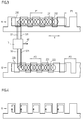
- the scanning unit 2 is in FIG. 3 schematically illustrated to explain the function of the inductive scanning in cooperation with the scale unit 1 in more detail.
- the planar excitation winding 210 is supplied with an exciter current such that a time-varying electromagnetic exciter field in the region of the division elements of the first measurement graduation 11 is generated.
- This excitation current has a frequency of 100 kHz to 10 MHz.
- the excitation winding 210 is spatially arranged in such a way that, in the opposite sequence of the dividing elements of the first measuring graduation 11, it forms an electromagnetic field that is as homogeneous as possible.
- the Abtastwindened 211, 212 are located within the excitation winding 210.
- the exciter field generated by the excitation winding 210 generated in the division elements eddy currents, which act as an opposing field against the exciter field.
- a voltage is induced due to their associated exciter field, which is dependent on the relative position to the electrically conductive dividing elements.
- the excitation winding 210 is thus inductively coupled to the Abtastwindept 211, 212 in dependence on the relative position of the dividing elements in the measuring direction X.
- the electromagnetic alternating field is modulated position-dependent by the dividing elements in the measuring direction X.
- the voltage induced in the sampling windings 211, 212 also varies in a position-dependent manner.
- the respectively induced voltage in the Abtastwindungen 211, 212 is supplied to an evaluation unit 3 in the form of the sampling signals S1, S11.
- the planar excitation winding 220 is also supplied with an exciter current such that a time-varying electromagnetic excitation field in the region of the division elements of the second measurement graduation 12 is generated.
- This excitation current has a frequency of a few MHz.
- the excitation winding 220 is spatially arranged in such a way that it forms an electromagnetic field that is as homogeneous as possible in the opposite sequence of the dividing elements.
- the Abtastwindened 221, 222 are located within the excitation winding 220.
- the excitation field generated by the excitation winding 220 generates eddy currents in the division elements, which act as an opposing field against the exciter field.
- a voltage is induced due to their associated excitation field, which is dependent on the relative position to the electrically conductive dividing elements.
- the exciter winding 220 is thus inductively coupled to the Abtastwindept 221, 222 in dependence on the relative position of the dividing elements in the measuring direction X.
- the alternating electromagnetic field is modulated position-dependent by the division elements in the measuring direction X, thereby varying the voltage induced in the Abtastwindened 221, 222 voltage depending on the position.
- the voltage induced in each of the sampling windings 221, 222 is supplied to an evaluation unit 3 in the form of the sampling signals S2, S21.
- the scanning signals S1, S11, S2, S21 are applied to the evaluation unit 3 of the scanning unit 2, which is configured to generate from the comparison of the phase positions in a known manner a beat signal indicating the unique absolute position AP of the scanning unit 2 relative to the scale unit 1.
- the measuring range to be coded absolutely depends in a known way on the chosen difference between the two graduation periods P1, P2. It is particularly advantageous if the number of graduation periods P1 and the number of graduation periods P2 differ by 1 over the entire measuring range to be coded absolutely.
- the absolute position AP is provided as a digital data word at the output of the scanning unit 2, the output preferably being in serial form.
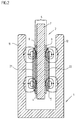
- the structure of the scanning unit 2 is based on the sectional view FIG. 2 explained in more detail.
- the first coil assembly 21, comprising the Excitation winding 210 and the Abtastwindungen 211, 212, is disposed on a first circuit board 4 at a small sampling distance to the first measuring graduation 11.
- the second coil arrangement 22, comprising the excitation winding 220 and the sampling windings 221, 222, is arranged on a second printed circuit board 5 at a small scanning distance from the second measuring graduation 12. Between the first coil arrangement 21 and the second coil arrangement 22, an intermediate layer 6 of soft magnetic material is arranged.
- the soft magnetic material as an intermediate layer 6 has the function of leading out of the first coil assembly 21 field lines of the alternating magnetic field in a layer of the material of the intermediate layer 6 and thus to form a closed and spatially limited magnetic circuit, and emanating from the second coil assembly 22nd To conduct field lines of the alternating magnetic field in a layer of the material of the intermediate layer 6 and thus to form a closed and spatially limited magnetic circuit.
- the intermediate layer 6 thereby separates the field lines starting from the first coil arrangement 21 from the field lines starting from the second coil arrangement 22.
- the intermediate layer consists of a soft magnetic core 7, which is provided on both sides with a respective layer 8, 9 of an electrically non-conductive soft magnetic material. Due to the poor electrical conductivity at a frequency of alternating magnetic fields of a few MHz (about 2 MHz) no eddy currents can be generated in the layers 8, 9, which attenuate the excitation field of the respective coil arrangement 21, 22. Due to the relatively high permeability (much greater than 1) of the layers 8, 9, the excitation field is conducted in the layers 8, 9 and thus reinforced. This prevents that too much magnetic flux reaches the core 7, so that there can be no eddy currents that could dampen the excitation field.
- the thickness of the layers 8, 9 is preferably in each case 100 ⁇ m to 1000 ⁇ m.
- the core 7 consists of a soft magnetic electrically conductive metal. The material used for the core is particularly soft magnetic steel. The thickness of the core 7 is a few mm.
- the permeability of the core 7 is preferably greater than the permeability of the two layers 8, 9. This ensures that the flux density in the core 7 is greater than in the layers 8, 9. External magnetic fields (interference fields) are therefore largely in the core 7 and the layers 8, 9 are not so easy to saturation.
- the permeability of the core 7 is in particular many times greater than the permeability of the layers 8, 9. If the permeability of the core is of the order of 300, the permeability of the layers should be of the order of 100 or less, at frequencies of 100 kHz to 10 MHz.
- electrically nonconductive matrix material in which soft magnetic particles are embedded is particularly suitable for the layers 8, 9.
- the layers 8, 9 can therefore be formed by a film of Flux Field Directional material.
- a matrix material is plastic, in particular epoxy resin, in which the soft magnetic particles are mixed in powder form.
- the centrally located core 7, the layers 8, 9 disposed thereon on both sides, the printed circuit boards 4, 5 applied thereon, and the planar coil assemblies 21, 22 applied thereto form a sandwich-type stack. This results in a compact construction and by the metal core 7, a mechanically stable construction is achieved.
- the layers 8, 9 and the circuit boards 4, 5 can also be produced together in the form of prepregs, which comprise fibers, matrix material and soft magnetic particles.
- the core 7, the layers 8, 9 and the printed circuit boards 4, 5 may form a multilayer structure, wherein the individual layers are pressed together under the influence of heat. The result is a rigid and compact sandwich-like structure.
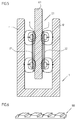
- the soft magnetic intermediate layer 6.1 in this case consists of a mu-metal.
- the layers 8, 9 are not imperative, so that the circuit boards 4, 5 can be applied with the coil assemblies 21, 22 directly on the Mu metal.
- the intermediate layer 6.1 in the form of a mu-metal is electrically conductive, but due to the extremely high permeability in alternating fields in the order of 2 MHz, the Endringtiefe the alternating fields is very low and propagate only in a few microns depth, so that the effective electrical resistance is very large and therefore again no or only negligible eddy currents arise, which counteract the excitation field of the respective coil assembly and can dampen it.
- the scale unit 1 is formed of a U-profile, in or on the two mutually parallel legs, the measuring divisions 11, 12 are formed.
- the first measuring graduation 11 is formed in one of the two legs and the second measuring graduation 12 is formed in the opposite and parallel thereto extending further leg of the U-profile.
- the scale unit 1 encompasses, as it were, the scanning unit 2 or 2.1.
- the dividing elements form in the exemplary embodiment inductive coupling elements, which modulate the strength of the inductive coupling between the excitation winding 210, 220 and the Abtastwindung 211, 212, 221, 222 depending on the position by each form eddy currents in a dividing element, which act against the exciter field.
- a material for the scale unit 1 is particularly suitable in this case, highly electrically conductive and non-magnetic material, such as aluminum.
- FIG. 1 shows a particularly advantageous embodiment of the scale unit 1 in the form of a U-profile, wherein the first measuring graduation 11 and the second measuring graduation 12 each consist of a sequence of teeth and tooth spaces.
- the scale unit 1 is particularly resistant to bending if the tooth gaps do not reach the bottom of the U-profile, ie, two webs extending on both sides adjacent to the bottom of the U-profile still extend in the measuring direction X.
- the embodiment of the scale unit 1 as a U-profile has the advantage that the scale unit 1 is made in one piece and the measuring divisions 11, 12 can be introduced aligned with each other in the required accuracy.
- the first measuring graduation 11 and the second measuring graduation 12 can be introduced by punching, cutting by means of laser or water jet in a metal strip, which is then bent to the U-profile.
- the U-profile, especially for use as a linear scale unit 1 has the advantage of high bending stiffness and is self-supporting and therefore easy to handle as a scale unit 1.
- the dividing elements of the scale unit 100 may also be in accordance with FIG. 6 be executed.
- the tooth spaces are each replaced by a material weakening, and the dividing elements are designed as elevations pointing in the direction of the scanning unit 2.
- This alternative embodiment can also be provided in the two opposing legs of a U-profile, resulting in a particularly rigid structure.
- the pitch period P1 of the first measurement pitch 11 coincides with the pitch period P1 of the associated sampling windings 211, 212 and the pitch period P2 of the second measurement pitch 12 coincides with the pitch period P2 of the associated sampling windings 221, 222 P1 are slightly different from P2.
- the pitch period of the sample turns for sampling the first measurement pitch 11 and the pitch period of the sample turns for sampling the second measurement pitch 12 may be identical, as in FIG EP 2 851 655 A1 explained.
- the dividing elements form inductive coupling elements which modulate the strength of the inductive coupling between the exciter winding 210, 220 and the Abtastwindung 211, 212, 221, 222 depending on the position by each form eddy currents in a dividing element, which against the exciter field - so flow-damping - act.
- the scale unit can also be designed so that the dividing elements act to increase the flow.
- the scale unit made of plastic, which is filled with soft magnetic material or ferrite, for example in the form of powder. The scale unit can then be designed as an injection molded part.
- the first measuring graduation of the scale unit may be a chain code.
- the chain code consists in a known manner of a sequence of bits, several of which are scanned in succession in the measuring direction simultaneously and form the absolute position uniquely determining code word as a coarse absolute position.
- the second measuring graduation may be a periodic incremental division, which further subdivides, by interpolation, the absolute position measured by the chain code and forms a fine position.
- the evaluation unit combines the coarse absolute position of the chain code and the fine position of the incremental graduation into a resulting absolute position.
- a measurement graduation may also comprise a plurality of tracks each having a periodic incremental graduation.
- the scale unit can be assigned in a manner not shown for position measurement and multiple scanning units. This can be used for redundant position measurement, or even to ensure uninterrupted position measurement across a burst, in the scan of a plurality of consecutively arranged abutted scale units, switching at the impact of one scanning unit to another scanning unit.
- the invention By the invention, a thickness of the entire position measuring device of a few mm is possible.
- the structure is mechanically very stable and largely immune to interference.
- An absolute position measurement is possible in the smallest of spaces.
- the position measuring device according to the invention is particularly suitable for transport systems and in automation technology in conjunction with linear drives.
- the inductive position measuring device according to the invention can be designed as a length measuring device or as an angle measuring device.
Landscapes
- Physics & Mathematics (AREA)
- General Physics & Mathematics (AREA)
- Transmission And Conversion Of Sensor Element Output (AREA)
- Measurement Of Length, Angles, Or The Like Using Electric Or Magnetic Means (AREA)
Abstract
Description
- Induktive Positionsmesseinrichtungen dienen zur Bestimmung der Position zweier zueinander bewegbarer Bauteile. Sie werden beispielsweise als Drehgeber zur Bestimmung der Winkellage zweier relativ zueinander drehbaren Maschinenteile oder als Längenmesssystem zur direkten Messung von Längsverschiebungen entlang einer Achse verwendet.
- Derartige induktive Positionsmesseinrichtungen werden als Messgeräte für elektrische Antriebe zur Bestimmung der Relativbewegung bzw. der Relativlage von entsprechenden Maschinenteilen eingesetzt. In diesem Fall werden die erzeugten Positionswerte einer Folgeelektronik zur Ansteuerung der Antriebe über eine entsprechende Schnittstellenanordnung zugeführt. Man unterscheidet zwischen inkrementalen Positionsmesseinrichtungen und absoluten Positionsmesseinrichtungen. Zunehmend werden absolute Positionsmesseinrichtungen gefordert.
- Eine gattungsgemäße absolute induktive Positionsmesseinrichtung ist aus der
EP 1081454 B1 bekannt. Die Absolutposition wird durch induktive Abtastung zweier Messteilungen mit geringfügig unterschiedlichen periodischen Messteilungen gewonnen (Noniusprinzip), welche jeweils die Stärke der induktiven Kopplung zwischen einer Erregerwindung und einer Abtastwindung positionsabhängig beeinflussen. Die Spulenanordnungen zur Abtastung der beiden Messteilungen sind im Zwischenraum bzw. im Spalt zwischen den Messteilungen angeordnet. - Der Erfindung liegt die Aufgabe zugrunde, eine induktive Positionsmesseinrichtung zu schaffen mit der eine präzise Absolutposition ermittelt werden kann und die eine kompakte und robuste Bauweise aufweist.
- Diese Aufgabe wird erfindungsgemäß durch die Merkmale des Anspruches 1 gelöst.
- Die induktive Positionsmesseinrichtung umfasst demnach
- eine Maßstabeinheit mit einer in Messrichtung verlaufenden ersten Messteilung und einer parallel dazu verlaufenden und der ersten Messteilung gegenüberliegenden zweiten Messteilung;
- eine Abtasteinheit, die in einem Spalt zwischen der ersten Messteilung und der zweiten Messteilung angeordnet ist und zur Positionsmessung relativ zur Maßstabeinheit in Messrichtung verschiebbar ist, wobei die Abtasteinheit eine erste Spulenanordnung zur Abtastung der ersten Messteilung und zur Erzeugung eines ersten positionsabhängigen Abtastsignals umfasst und die Abtasteinheit eine der ersten Spulenanordnung gegenüberliegende zweite Spulenanordnung zur Abtastung der zweiten Messteilung und zur Erzeugung eines zweiten positionsabhängigen Abtastsignals umfasst, wobei
zwischen der ersten Spulenanordnung und der zweiten Spulenanordnung zumindest eine Zwischenlage aus weichmagnetischem Material angeordnet ist. - Weichmagnetisches Material sind ferromagnetische Materialien, die sich in einem Magnetfeld leicht magnetisieren lassen. Die magnetische Polarisation in dem Material verstärkt ein äußeres Magnetfeld um die Werkstoffpermeabilität. Das weichmagnetische Material kann in Form von einem massiven Metall, als gebundenes Metallpulver, in Form von keramischen Materialien, sogenannte Ferrite, oder als kunststoffgebundenes Ferrit-Pulver vorliegen.
- Das weichmagnetische Material als Zwischenlage hat die Funktion die von der ersten Spulenanordnung ausgehenden Feldlinien des magnetischen Wechselfeldes in der Schicht des Materials der Zwischenlage zu leiten und somit einen geschlossenen und räumlich begrenzten magnetischen Kreis zu bilden, sowie die von der zweiten Spulenanordnung ausgehenden Feldlinien des magnetischen Wechselfeldes in der Schicht des Materials der Zwischenlage zu leiten und somit einen geschlossenen und räumlich begrenzten magnetischen Kreis zu bilden. Die Zwischenlage trennt dadurch die Feldlinien ausgehend von der ersten Spulenanordnung von den Feldlinien ausgehend von der zweiten Spulenanordnung.
- Besonders geeignet als Zwischenlage ist ein sandwichartiger Aufbau, bestehend aus einem Kern und eine darauf beidseitig angeordnete Schicht aus weichmagnetischem Material, das bei Wechselfeldern in der Größenordnung um 2 MHz einen großen elektrischen Widerstand, z.B. in der Größenordnung von 1 x 10⁶ Ω aufweist, also praktisch elektrisch nichtleitend ist. Ein derartiges Material ist FFD-Material (Flux Field Directional Material) und ist in Form einer Folie als "sintered ferrite sheet" im Handel erhältlich. Aufgrund der schlechten elektrischen Leitfähigkeit können in diesem Material keine Wirbelströme entstehen, die das Erregerfeld der jeweiligen Spulenanordnung dämpfen.
- Der Kern besteht vorzugsweise ebenfalls aus einem weichmagnetischen Material. Insbesondere ist die Permeabilität des Materials des Kerns deutlich - vorzugsweise um ein Vielfaches - größer als die Permeabilität der beidseitig angeordneten Schichten. In diesem Fall nimmt der Kern den von einem äußeren Magnetfeld ausgehenden Störfluss auf und die Schichten geraten nicht in Sättigung. Ist die Positionsmesseinrichtung nämlich einem äußeren Magnetfeld ausgesetzt muss verhindert werden, dass dieses äußere Magnetfeld die funktionalen Schichten sättigt, da sonst die flussverstärkende Wirkung nicht mehr gegeben ist. Als Material für den Kern eignet sich insbesondere weichmagnetischer Stahl.
- Die metallene Zwischenlage kann auch Mu-Metall sein, also ein Metall mit einer sehr hohen Permeabilität von über 10.000. Dieses weichmagnetische Material ist gut elektrisch leitfähig, aufgrund der extrem hohen Permeabilität bei Wechselfeldern in der Größenordnung von 2 MHz ist die Endringtiefe der Wechselfelder sehr gering und sie breiten sich nur in wenigen µm Tiefe aus, sodass der effektive elektrische Widerstand sehr groß ist und daher wiederum keine bzw. nur vernachlässigbare Wirbelströme entstehen, die dem Erregerfeld der jeweiligen Spulenanordnung entgegenwirken und es dämpfen können.
- Vorteilhafte Ausbildungen der Erfindung entnimmt man den abhängigen Ansprüchen.
- Einzelheiten und Vorteile der erfindungsgemäßen induktiven Positionsmesseinrichtung ergeben sich aus der nachfolgenden Beschreibung von Ausführungsbeispielen anhand der beiliegenden Figuren.
- Es zeigen
- Figur 1
- eine perspektivische Ansicht einer ersten induktiven Positionsmesseinrichtung gemäß der Erfindung;
- Figur 2
- einen Querschnitt der induktiven Positionsmesseinrichtung aus
Figur 1 ; - Figur 3
- die Ausgestaltung und Abtastung der ersten Messteilung und der zweiten Messteilung im Detail;
- Figur 4
- die sich in der ersten Messteilung ausbildenden Wirbelströme;
- Figur 5
- eine zweite induktive Positionsmesseinrichtung gemäß der Erfindung im Schnitt, und
- Figur 6
- eine alternative Ausgestaltung einer Maßstabeinheit.
- Anhand der
Figuren 1 bis 4 wird ein erstes Ausführungsbeispiel der Erfindung näher erläutert. DieFigur 1 zeigt eine Maßstabeinheit 1 mit zwei in Messrichtung X verlaufenden Messteilungen 11 und 12, die einander gegenüberliegend angeordnet sind und zwischen ihnen einen Spalt ausbilden. Die erste Messteilung 11 weist Teilungselemente mit einer ersten Teilungsperiode P1 auf und die zweite Messteilung 12 weist Teilungselemente mit einer zweiten Teilungsperiode P2 auf. Die periodisch angeordneten Teilungselemente der beiden Messteilungen 11, 12 sind induktiv abtastbar ausgestaltet. Hierzu bestehen die Messteilungen 11, 12 jeweils aus einer periodischen Abfolge von in Messrichtung X voneinander beabstandeten elektrisch leitfähigen Teilungselementen. Im dargestellten Ausführungsbeispiel sind diese Teilungselemente flächige Rechtecke. Die Teilungselemente können aber auch andere Formen aufweisen, beispielsweise eine gekrümmte Außenkontur oder auch dreieckförmig. Die Teilungselemente bilden induktive Koppelelemente, welche die Stärke der induktiven Kopplung zwischen einer Erregerwindung 210, 220 und einer Abtastwindung 211, 212, 221, 222 positionsabhängig modulieren, indem sich in einem Teilungselement Wirbelströme ausbilden, die gegen das Erregerfeld wirken. InFigur 4 sind schematisch die sich in den Teilungselementen der Messteilung 11 ausbildenden Wirbelströme dargestellt. - Die Teilungsperiode P1 der ersten Messteilung 11 und die Teilungsperiode P2 der zweiten Messteilung 12 weichen nur geringfügig voneinander ab, so dass daraus eine Absolutposition AP über mehrere dieser Teilungsperioden P1, P2 abgeleitet werden kann. Der absoluten Positionsmessung liegt also das Noniusprinzip zugrunde.
- Die induktive Positionsmesseinrichtung umfasst darüber hinaus eine Abtasteinheit 2 zur Abtastung der beiden Messteilungen 11 und 12 der Maßstabeinheit 1, die in dem Spalt zwischen der ersten Messteilung 11 und der zweiten Messteilung 12 angeordnet ist. Zur Positionsmessung ist die Abtasteinheit 2 in Messrichtung X relativ zur Maßstabeinheit 1 verschiebbar. Die Abtasteinheit 2 beinhaltet eine erste Spulenanordnung 21 zur Abtastung der ersten Messteilung 11 und zur Erzeugung zumindest eines ersten positionsabhängigen Abtastsignals S1. Die Abtasteinheit 2 beinhaltet eine zweite Spulenanordnung 22 zur Abtastung der zweiten Messteilung 12 und zur Erzeugung zumindest eines zweiten positionsabhängigen Abtastsignals S2.
- Die erste Spulenanordnung 21 weist eine erste Erregerwindung 210 und mehrere erste gegeneinander phasenverschobene periodische Abtastwindungen 211,212 auf. Ebenso weist die zweite Spulenanordnung 22 zur Abtastung der zweiten Messteilung 12 eine zweite Erregerwindung 220 und mehrere zweite gegeneinander phasenverschobene periodische Abtastwindungen 221, 222 auf. Die ersten Abtastwindungen 211, 212 umfassen jeweils mehrere in Messrichtung X verlaufende periodische Windungen zur gleichzeitigen Abtastung mehrerer in Messrichtung X angeordneter Teilungselemente der ersten Messteilung 11 und zur Bildung mehrerer gegeneinander phasenverschobener erster Abtastsignale S1, S11 mit der Signalperiode P1. Die zweiten Abtastwindungen 221, 222 umfassen jeweils mehrere in Messrichtung X verlaufende periodische Windungen zur gleichzeitigen Abtastung mehrerer in Messrichtung X angeordneter Teilungselemente der zweiten Messteilung 12 und zur Bildung mehrerer gegeneinander phasenverschobener zweiter Abtastsignale S2, S21 mit der Signalperiode P2.
- Die Abtasteinheit 2 ist in
Figur 3 schematisch dargestellt, um die Funktion der induktiven Abtastung beim Zusammenwirken mit der Maßstabeinheit 1 näher zu erläutern. - Die planare Erregerwindung 210 wird mit einem Erregerstrom derart gespeist, dass ein zeitlich wechselndes elektromagnetisches Erregerfeld im Bereich der Teilungselemente der ersten Messteilung 11 erzeugt wird. Dieser Erregerstrom weist eine Frequenz von 100 kHz bis 10 MHz auf. Die Erregerwindung 210 ist derart räumlich angeordnet, dass sie in der gegenüberliegenden Abfolge der Teilungselemente der ersten Messteilung 11 ein möglichst homogenes elektromagnetisches Feld ausbildet.
- Die Abtastwindungen 211, 212 befinden sich innerhalb der Erregerwindung 210. Das von der Erregerwindung 210 generierte Erregerfeld generiert in den Teilungselementen Wirbelströme, die als Gegenfeld gegen das Erregerfeld wirken. In den Abtastwindungen 211, 212 wird aufgrund des ihnen zugeordneten Erregerfeldes eine Spannung induziert, die von der relativen Lage zu den elektrisch leitenden Teilungselementen abhängig ist. Die Erregerwindung 210 ist also mit den Abtastwindungen 211, 212 in Abhängigkeit der relativen Lage der Teilungselemente dazu in Messrichtung X induktiv gekoppelt. Das elektromagnetische Wechselfeld wird durch die Teilungselemente in Messrichtung X positionsabhängig moduliert, dadurch variiert auch die in den Abtastwindungen 211, 212 induzierte Spannung positionsabhängig. Die in den Abtastwindungen 211, 212 jeweils induzierte Spannung wird einer Auswerteeinheit 3 in Form der Abtastsignale S1, S11 zugeführt.
- Die planare Erregerwindung 220 wird ebenso mit einem Erregerstrom derart gespeist, dass ein zeitlich wechselndes elektromagnetisches Erregerfeld im Bereich der Teilungselemente der zweiten Messteilung 12 erzeugt wird. Dieser Erregerstrom weist eine Frequenz von einigen MHz auf. Die Erregerwindung 220 ist derart räumlich angeordnet, dass sie in der gegenüberliegenden Abfolge der Teilungselemente ein möglichst homogenes elektromagnetisches Feld ausbildet.
- Die Abtastwindungen 221, 222 befinden sich innerhalb der Erregerwindung 220. Das von der Erregerwindung 220 generierte Erregerfeld generiert in den Teilungselementen Wirbelströme, die als Gegenfeld gegen das Erregerfeld wirken. In den Abtastwindungen 221, 222 wird aufgrund des ihnen zugeordneten Erregerfeldes eine Spannung induziert, die von der relativen Lage zu den elektrisch leitenden Teilungselementen abhängig ist. Die Erregerwindung 220 ist also mit den Abtastwindungen 221, 222 in Abhängigkeit der relativen Lage der Teilungselemente dazu in Messrichtung X induktiv gekoppelt. Das elektromagnetische Wechselfeld wird durch die Teilungselemente in Messrichtung X positionsabhängig moduliert, dadurch variiert auch die in den Abtastwindungen 221, 222 induzierte Spannung positionsabhängig. Die in den Abtastwindungen 221, 222 jeweils induzierte Spannung wird einer Auswerteeinheit 3 in Form der Abtastsignale S2, S21 zugeführt.
- Die Abtastsignale S1, S11, S2, S21 liegen an der Auswerteeinheit 3 der Abtasteinheit 2 an, welche dazu konfiguriert ist aus dem Vergleich der Phasenlagen in bekannter Weise ein Schwebungssignal zu erzeugen, das die eindeutige Absolutposition AP der Abtasteinheit 2 relativ zur Maßstabeinheit 1 angibt. Der absolut zu codierende Messbereich ist in bekannter Weise abhängig von dem gewählten Unterschied der beiden Teilungsperioden P1, P2. Besonders vorteilhaft ist, wenn sich über den gesamten absolut zu codierenden Messbereich die Anzahl der Teilungsperioden P1 und die Anzahl der Teilungsperioden P2 um 1 unterscheidet. Die Absolutposition AP wird als digitales Datenwort am Ausgang der Abtasteinheit 2 zur Verfügung gestellt, wobei die Ausgabe vorzugsweise in serieller Form erfolgt.
- Der Aufbau der Abtasteinheit 2 wird anhand der Schnittdarstellung
Figur 2 näher erläutert. Die erste Spulenanordnung 21, umfassend die Erregerwindung 210 und die Abtastwindungen 211, 212, ist auf einer ersten Leiterplatte 4 in geringem Abtastabstand zur ersten Messteilung 11 angeordnet. Die zweite Spulenanordnung 22, umfassend die Erregerwindung 220 und die Abtastwindungen 221, 222, ist auf einer zweiten Leiterplatte 5 in geringem Abtastabstand zur zweiten Messteilung 12 angeordnet. Zwischen der ersten Spulenanordnung 21 und der zweiten Spulenanordnung 22 ist eine Zwischenlage 6 aus weichmagnetischem Material angeordnet. - Das weichmagnetische Material als Zwischenlage 6 hat die Funktion die von der ersten Spulenanordnung 21 ausgehenden Feldlinien des magnetischen Wechselfeldes in einer Schicht des Materials der Zwischenlage 6 zu leiten und somit einen geschlossenen und räumlich begrenzten magnetischen Kreis zu bilden, sowie die von der zweiten Spulenanordnung 22 ausgehenden Feldlinien des magnetischen Wechselfeldes in einer Schicht des Materials der Zwischenlage 6 zu leiten und somit einen geschlossenen und räumlich begrenzten magnetischen Kreis zu bilden. Die Zwischenlage 6 trennt dadurch die Feldlinien ausgehend von der ersten Spulenanordnung 21 von den Feldlinien ausgehend von der zweiten Spulenanordnung 22.
- Im ersten Ausführungsbeispiel besteht die Zwischenlage aus einem weichmagnetischen Kern 7, der beidseitig mit jeweils einer Schicht 8, 9 aus einem elektrisch nichtleitenden weichmagnetischen Material versehen ist. Aufgrund der schlechten elektrischen Leitfähigkeit bei einer Frequenz magnetischer Wechselfelder von einigen MHz (etwa 2 MHz) können in den Schichten 8, 9 keine Wirbelströme entstehen, die das Erregerfeld der jeweiligen Spulenanordnung 21, 22 dämpfen. Aufgrund der relativ hohen Permeabilität (sehr viel größer als 1) der Schichten 8, 9 wird das Erregerfeld in den Schichten 8, 9 geleitet und damit verstärkt. Dadurch wird verhindert, dass zu viel magnetischer Fluß bis zum Kern 7 gelangt, so dass dort keine Wirbelströme entstehen können, die das Erregerfeld dämpfen könnten. Die Dicke der Schichten 8, 9 beträgt vorzugsweise jeweils 100 µm bis 1000 µm. In vorteilhafter Weise besteht der Kern 7 aus einem weichmagnetischen elektrisch leitfähigen Metall. Als Material für den Kern eignet sich besonders weichmagnetischer Stahl. Die Dicke des Kerns 7 beträgt wenige mm.
- Die Permeabilität des Kerns 7 ist vorzugsweise größer als die Permeabilität der beiden Schichten 8, 9. Damit wird erreicht, dass die Flussdichte im Kern 7 größer als in den Schichten 8, 9 ist. Externe Magnetfelder (Störfelder) verlaufen daher zum Großteil im Kern 7 und die Schichten 8, 9 kommen nicht so leicht in Sättigung. Die Permeabilität des Kerns 7 ist insbesondere um ein Vielfaches größer ist als die Permeabilität der Schichten 8, 9. Ist die Permeabilität des Kerns in der Größenordnung von 300, sollte die Permeabilität der Schichten in der Größenordnung von 100 oder kleiner sein, bei Frequenzen von 100 kHz bis 10 MHz.
- Für die Schichten 8, 9 eignet sich insbesondere jeweils elektrisch nicht leitfähiges Matrixmaterial, in das weichmagnetische Partikel eingebettet sind. Die Schichten 8, 9 können daher von einer Folie aus Flux Field Directional Material gebildet sein. Als Matrixmaterial eignet sich Kunststoff, insbesondere Epoxidharz, in das die weichmagnetischen Partikel in Pulverform eingemischt sind.
- Der mittig angeordnete Kern 7, die beidseitig darauf angeordneten Schichten 8, 9, die darauf aufgebrachten Leiterplatten 4, 5 und die darauf aufgebrachten planaren Spulenanordnungen 21, 22 bilden einen sandwichartigen Stapel. Es ergibt sich ein kompakter Aufbau und durch den metallenen Kern 7 wird auch ein mechanisch stabiler Aufbau erreicht.
- Die Schichten 8, 9 und die Leiterplatten 4, 5 können auch gemeinsam in Form von Prepregs hergestellt sein, welche Fasern, Matrixmaterial und weichmagnetische Partikel aufweisen. Der Kern 7, die Schichten 8, 9 und die Leiterplatten 4, 5 können einen Multilayer-Aufbau bilden, wobei die einzelnen Lagen unter Wärmeeinfluss miteinander verpresst sind. Es ergibt sich ein steifer und kompakter sandwichartiger Aufbau.
- In der
Figur 5 ist ein alternativer Aufbau einer Abtasteinheit 2.1 dargestellt. Die weichmagnetische Zwischenlage 6.1 besteht in diesem Fall aus einem Mu-Metall. In diesem Ausführungsbeispiel sind die Schichten 8, 9 nicht zwingend erforderlich, so dass die Leiterplatten 4, 5 mit den Spulenanordnungen 21, 22 direkt auf das Mu-Metall aufgebracht werden können. Die Zwischenlage 6.1 in Form eines Mu-Metalls ist elektrisch leitfähig, aufgrund der extrem hohen Permeabilität bei Wechselfeldern in der Größenordnung von 2 MHz ist die Endringtiefe der Wechselfelder aber sehr gering und breiten sich nur in wenigen µm Tiefe aus, so dass der effektive elektrische Widerstand sehr groß ist und daher wiederum keine bzw. nur vernachlässigbare Wirbelströme entstehen, die dem Erregerfeld der jeweiligen Spulenanordnung entgegenwirken und es dämpfen können. - In den obigen Ausführungsbeispielen ist die Maßstabeinheit 1 gebildet aus einem U-Profil, in bzw. an deren zwei parallel zueinander verlaufenden Schenkeln die Messteilungen 11, 12 ausgebildet sind. Die erste Messteilung 11 ist in einem der beiden Schenkel ausgebildet und die zweite Messteilung 12 in dem gegenüberliegenden und parallel dazu verlaufenden weiteren Schenkel des U-Profils ausgebildet. Die Maßstabeinheit 1 umgreift sozusagen die Abtasteinheit 2 bzw. 2.1.
- Die Teilungselemente bilden im Ausführungsbeispiel induktive Koppelelemente, welche die Stärke der induktiven Kopplung zwischen der Erregerwindung 210, 220 und der Abtastwindung 211, 212, 221, 222 positionsabhängig modulieren, indem sich in einem Teilungselement jeweils Wirbelströme ausbilden, die gegen das Erregerfeld wirken. Als Material für die Maßstabeinheit 1 eignet sich in diesem Fall insbesondere gut elektrisch leitfähiges und unmagnetisches Material, beispielsweise Aluminium.
-
Figur 1 zeigt eine besonders vorteilhafte Ausgestaltung der Maßstabeinheit 1 in Form eines U-Profils, wobei die erste Messteilung 11 und die zweite Messteilung 12 jeweils aus einer Abfolge von Zähnen und Zahnlücken bestehen. Besonders biegesteif ist die Maßstabeinheit 1, wenn die Zahnlücken nicht bis zum Grund des U-Profils reichen, also beidseitig angrenzend an den Grund des U-Profils noch in Messrichtung X verlaufende durchgehende Stege verbleiben. - Die Ausführungsform der Maßstabeinheit 1 als U-Profil hat den Vorteil, dass die Maßstabeinheit 1 einstückig ausgeführt ist und die Messteilungen 11, 12 in der erforderlichen Genauigkeit zueinander ausgerichtet eingebracht werden können. Die erste Messteilung 11 und die zweite Messteilung 12 können durch Stanzen, Schneiden mittels Laser oder Wasserstrahl in einem Blechstreifen eingebracht werden, der danach zu dem U-Profil gebogen wird. Das U-Profil hat besonders zur Verwendung als lineare Maßstabeinheit 1 den Vorteil der hohen Biegesteifigkeit und ist selbsttragend und daher als Maßstabeinheit 1 gut handhabbar.
- Alternativ können die Teilungselemente der Maßstabeinheit 100 auch gemäß der
Figur 6 ausgeführt sein. Die Zahnlücken sind in diesem Fall jeweils ersetzt durch eine Materialschwächung und die Teilungselemente sind als in Richtung der Abtasteinheit 2 weisende Erhebungen ausgebildet. Diese alternative Ausgestaltung kann auch in den beiden einander gegenüberliegenden Schenkeln eines U-Profils vorgesehen sein, wobei sich ein besonders biegesteifer Aufbau ergibt. - In den oben erläuterten Ausführungsbeispielen und Nutzung des Nonius-Prinzips stimmt die Teilungsperiode P1 der ersten Messteilung 11 mit der Teilungsperiode P1 der zugehörigen Abtastwindungen 211, 212 sowie die Teilungsperiode P2 der zweiten Messteilung 12 mit der Teilungsperiode P2 der zugehörigen Abtastwindungen 221, 222 überein, wobei P1 von P2 geringfügig voneinander abweichen. Bei Nutzung des Nonius-Prinzips kann alternativ die Teilungsperiode der Abtastwindungen zur Abtastung der ersten Messteilung 11 und die Teilungsperiode der Abtastwindungen zur Abtastung der zweiten Messteilung 12 auch identisch sein, wie in der
EP 2 851 655 A1 erläutert. - In den oben erläuterten Ausführungsbeispielen bilden die Teilungselemente induktive Koppelelemente, welche die Stärke der induktiven Kopplung zwischen der Erregerwindung 210, 220 und der Abtastwindung 211, 212, 221, 222 positionsabhängig modulieren, indem sich in einem Teilungselement jeweils Wirbelströme ausbilden, die gegen das Erregerfeld - also flussdämpfend - wirken. Die Maßstabeinheit kann aber auch dazu ausgelegt sein, dass die Teilungselemente flussverstärkend wirken. In diesem Fall kann die Maßstabeinheit aus Kunststoff bestehen, der mit weichmagnetischem Material oder Ferrit z.B. in Form von Pulver, gefüllt ist. Die Maßstabeinheit kann dann als Spritzgussteil ausgeführt sein.
- In nicht gezeigter Weise kann die erste Messteilung der Maßstabeinheit ein Kettencode sein. Der Kettencode besteht in bekannter Weise aus einer Abfolge von Bits, von denen mehrere in Messrichtung aufeinanderfolgende gleichzeitig abgetastet werden und ein die Absolutposition eindeutig bestimmendes Codewort als grobe Absolutposition bilden. In diesem Fall kann die zweite Messteilung eine periodische Inkrementalteilung sein, die durch Interpolation die vom Kettencode gemessene Absolutposition weiter unterteilt und eine Feinposition bildet. Die Auswerteeinheit kombiniert die grobe Absolutposition des Kettencodes und die Feinposition der Inkrementalteilung zu einer resultierenden Absolutposition.
- Alternativ kann eine Messteilung auch mehrere Spuren mit jeweils einer periodischen Inkrementalteilung umfassen.
- Der Maßstabeinheit können in nicht gezeigter Weise zur Positionsmessung auch mehrere Abtasteinheiten zugeordnet sein. Dies kann zur redundanten Positionsmessung dienen, oder auch zur Sicherstellung der ununterbrochenen Positionsmessung über einen Stoß hinweg, bei der Abtastung von mehreren nacheinander angeordneten gestoßenen Maßstabeinheiten, wobei am Stoß von einer Abtasteinheiten auf eine andere Abtasteinheit umgeschaltet wird.
- Durch die Erfindung ist eine Dicke der gesamten Positionsmesseinrichtung von einigen wenigen mm möglich. Der Aufbau ist mechanisch besonders stabil und weitgehend störsicher. Eine absolute Positionsmessung ist auf engstem Raum möglich.
- Die erfindungsgemäße Positionsmesseinrichtung ist insbesondere für Transportsysteme und in der Automatisierungstechnik in Verbindung mit Linearantrieben geeignet.
- Die induktive Positionsmesseinrichtung gemäß der Erfindung kann als Längenmesseinrichtung oder als Winkelmesseinrichtung ausgebildet sein.
Claims (12)
- Induktive Positionsmesseinrichtung zur absoluten Positionsmessung, umfassend- eine Maßstabeinheit (1, 100) mit einer in Messrichtung (X) verlaufenden ersten Messteilung (11) und einer parallel dazu verlaufenden und der ersten Messteilung (11) gegenüberliegenden zweiten Messteilung (12);- eine Abtasteinheit (2, 2.1), die in einem Spalt zwischen der ersten Messteilung (11) und der zweiten Messteilung (12) angeordnet ist und zur Positionsmessung relativ zur Maßstabeinheit (1, 100) in Messrichtung (X) verschiebbar ist, wobei die Abtasteinheit (2, 2.1) eine erste Spulenanordnung (21) zur Abtastung der ersten Messteilung (11) und zur Erzeugung eines ersten positionsabhängigen Abtastsignals (S1, S11) umfasst und die Abtasteinheit (2, 2.1) eine der ersten Spulenanordnung (21) gegenüberliegende zweite Spulenanordnung (22) zur Abtastung der zweiten Messteilung (12) und zur Erzeugung eines zweiten positionsabhängigen Abtastsignals (S2, S21) umfasst,
dadurch gekennzeichnet, dass
zwischen der ersten Spulenanordnung (21) und der zweiten Spulenanordnung (22) zumindest eine Zwischenlage (6, 6.1) aus weichmagnetischem Material angeordnet ist. - Induktive Positionsmesseinrichtung nach Anspruch 1, wobei die Zwischenlage (6) aus einem weichmagnetischen Kern (7) und beidseitig darauf angeordneten elektrisch nicht leitfähigen weichmagnetischen Schichten (8, 9) besteht.
- Induktive Positionsmesseinrichtung nach Anspruch 2, wobei der Kern (7) aus einem weichmagnetischen elektrisch leitfähigem Metall besteht.
- Induktive Positionsmesseinrichtung nach Anspruch 2 oder 3, wobei die Permeabilität des Kerns (7) größer ist als die Permeabilität der beiden Schichten (8, 9).
- Induktive Positionsmesseinrichtung nach einem der vorhergehenden Ansprüche 2 bis 4, wobei die Schichten (8, 9) jeweils ein elektrisch nicht leitfähiges Matrixmaterial umfassen, in das weichmagnetische Partikel eingebettet sind.
- Induktive Positionsmesseinrichtung nach einem der vorhergehenden Ansprüche 2 bis 5, wobei der Kern (7) aus Stahl besteht und die Schichten (8, 9) jeweils eine Folie aus Flux Field Directional Material sind.
- Induktive Positionsmesseinrichtung nach Anspruch 1, wobei die Zwischenlage (6.1) ein Mu-Metall umfasst.
- Induktive Positionsmesseinrichtung nach einem der vorhergehenden Ansprüche, wobei die erste Messteilung (11) eine periodische Inkrementalteilung mit einer ersten Teilungsperiode (P1) ist und die zweite Messteilung (12) eine periodische Inkrementalteilung mit einer zweiten Teilungsperiode (P2) ist, die geringfügig von der ersten Teilungsperiode (P1) abweicht und die absolute Positionsmessung auf dem Nonius-Prinzip beruht.
- Induktive Positionsmesseinrichtung nach Anspruch 8, wobei die erste Spulenanordnung (21) und die zweite Spulenanordnung (22) jeweils eine Erregerwindung (210, 220) und jeweils mehrere gegeneinander phasenverschobene periodische Abtastwindungen (211, 212, 221, 222) zur gleichzeitigen Abtastung mehrerer Teilungsperioden der ihr zugeordneten Messteilung (11, 12) aufweist.
- Induktive Positionsmesseinrichtung nach einem der vorhergehenden Ansprüche, wobei die Abtasteinheit (2, 2.1) eine Auswerteeinheit (3) umfasst, welche dazu ausgelegt ist aus dem ersten positionsabhängigen Abtastsignal (S1, S11) und dem zweiten positionsabhängigen Abtastsignal (S2, S21) eine resultierende Absolutposition (AP) zu bilden und als digitales Datenwort am Ausgang zur Verfügung zu stellen.
- Induktive Positionsmesseinrichtung nach einem der vorhergehenden Ansprüche, wobei die Maßstabeinheit (1) ein U-Profil ist und die erste Messteilung (11) und die zweite Messteilung (12) einander gegenüberliegend an den zwei parallel zueinander verlaufenden Schenkeln des U-Profils ausgebildet sind.
- Induktive Positionsmesseinrichtung nach Anspruch 11, wobei die erste Messteilung (11) und die zweite Messteilung (12) aus einer Abfolge von Zähnen und Zahnlücken in den Schenkeln des U-Profils bestehen.
Applications Claiming Priority (1)
| Application Number | Priority Date | Filing Date | Title |
|---|---|---|---|
| DE102015224589.6A DE102015224589A1 (de) | 2015-12-08 | 2015-12-08 | Induktive Positionsmesseinrichtung |
Publications (2)
| Publication Number | Publication Date |
|---|---|
| EP3179214A1 true EP3179214A1 (de) | 2017-06-14 |
| EP3179214B1 EP3179214B1 (de) | 2018-08-01 |
Family
ID=56888996
Family Applications (1)
| Application Number | Title | Priority Date | Filing Date |
|---|---|---|---|
| EP16187795.6A Active EP3179214B1 (de) | 2015-12-08 | 2016-09-08 | Induktive positionsmesseinrichtung |
Country Status (6)
| Country | Link |
|---|---|
| US (1) | US9958296B2 (de) |
| EP (1) | EP3179214B1 (de) |
| JP (1) | JP6333345B2 (de) |
| CN (1) | CN106969695B (de) |
| DE (1) | DE102015224589A1 (de) |
| ES (1) | ES2683650T3 (de) |
Cited By (3)
| Publication number | Priority date | Publication date | Assignee | Title |
|---|---|---|---|---|
| WO2022156930A1 (de) * | 2021-01-21 | 2022-07-28 | HELLA GmbH & Co. KGaA | Länglicher körper mit cursorband für ein fahrzeugsystem eines fahrzeugs |
| WO2022156931A1 (de) * | 2021-01-21 | 2022-07-28 | HELLA GmbH & Co. KGaA | Induktiver linearwegsensor |
| WO2023227481A1 (de) * | 2022-05-21 | 2023-11-30 | Flux Gmbh | Mehrspuranordnung für linear- und winkelmesssysteme |
Families Citing this family (11)
| Publication number | Priority date | Publication date | Assignee | Title |
|---|---|---|---|---|
| EP3255384B1 (de) * | 2016-06-07 | 2018-11-28 | Dr. Johannes Heidenhain GmbH | Massverkörperung sowie positionsmesseinrichtung |
| US20190111800A1 (en) | 2017-10-16 | 2019-04-18 | Neapco Intellectual Property Holdings, Llc | High coverage battery usage monitor |
| DE102017222063A1 (de) * | 2017-12-06 | 2019-06-06 | Dr. Johannes Heidenhain Gmbh | Induktive Positionsmesseinrichtung |
| DE102018102698A1 (de) * | 2018-02-19 | 2019-08-22 | HELLA GmbH & Co. KGaA | Induktiver Positionssensor |
| JP7431032B2 (ja) * | 2019-12-23 | 2024-02-14 | 株式会社ミツトヨ | 電磁誘導式エンコーダ |
| CN116868028A (zh) * | 2021-01-21 | 2023-10-10 | 海拉有限双合股份公司 | 感应式的线性位移传感器 |
| US11940470B2 (en) | 2022-05-31 | 2024-03-26 | Allegro Microsystems, Llc | Current sensor system |
| US12352607B2 (en) * | 2022-06-28 | 2025-07-08 | Allegro Microsystems, Llc | Position sensing method |
| JP2024106417A (ja) * | 2023-01-27 | 2024-08-08 | 株式会社プロテリアル | 位置検出装置 |
| DE102023209159A1 (de) * | 2023-09-20 | 2025-03-20 | Infineon Technologies Ag | Induktives positionsbestimmungssystem mit variierender spulengeometrie und entsprechendes verfahren zur positionsbestimmung |
| US12455178B2 (en) | 2023-12-22 | 2025-10-28 | Allegro Microsystems, Llc | Inductive linear stroke sensor using dual tracks with different periodicity |
Citations (2)
| Publication number | Priority date | Publication date | Assignee | Title |
|---|---|---|---|---|
| EP2581711A2 (de) * | 2011-10-10 | 2013-04-17 | Advanced Sensor Technology Limited | Absolutpositionsmessvorrichtung und -verfahren |
| EP2851655A1 (de) * | 2013-09-19 | 2015-03-25 | Dr. Johannes Heidenhain GmbH | Induktive Positionsmesseinrichtung |
Family Cites Families (4)
| Publication number | Priority date | Publication date | Assignee | Title |
|---|---|---|---|---|
| DE19941464A1 (de) | 1999-09-01 | 2001-03-15 | Hella Kg Hueck & Co | Induktiver Positionssensor |
| DE10244234A1 (de) * | 2002-09-23 | 2004-03-25 | Dr. Johannes Heidenhain Gmbh | Positionsmesseinrichtung |
| DE102012223037A1 (de) * | 2012-12-13 | 2014-06-18 | Dr. Johannes Heidenhain Gmbh | Induktive Positionsmesseinrichtung |
| CN103206912A (zh) * | 2013-04-24 | 2013-07-17 | 四川大学 | 一种磁致伸缩位移传感器测量装置 |
-
2015
- 2015-12-08 DE DE102015224589.6A patent/DE102015224589A1/de not_active Withdrawn
-
2016
- 2016-09-08 ES ES16187795.6T patent/ES2683650T3/es active Active
- 2016-09-08 EP EP16187795.6A patent/EP3179214B1/de active Active
- 2016-11-21 US US15/356,698 patent/US9958296B2/en active Active
- 2016-11-30 CN CN201611078139.3A patent/CN106969695B/zh active Active
- 2016-12-07 JP JP2016237422A patent/JP6333345B2/ja active Active
Patent Citations (2)
| Publication number | Priority date | Publication date | Assignee | Title |
|---|---|---|---|---|
| EP2581711A2 (de) * | 2011-10-10 | 2013-04-17 | Advanced Sensor Technology Limited | Absolutpositionsmessvorrichtung und -verfahren |
| EP2851655A1 (de) * | 2013-09-19 | 2015-03-25 | Dr. Johannes Heidenhain GmbH | Induktive Positionsmesseinrichtung |
Cited By (6)
| Publication number | Priority date | Publication date | Assignee | Title |
|---|---|---|---|---|
| WO2022156930A1 (de) * | 2021-01-21 | 2022-07-28 | HELLA GmbH & Co. KGaA | Länglicher körper mit cursorband für ein fahrzeugsystem eines fahrzeugs |
| WO2022156931A1 (de) * | 2021-01-21 | 2022-07-28 | HELLA GmbH & Co. KGaA | Induktiver linearwegsensor |
| US12522286B2 (en) | 2021-01-21 | 2026-01-13 | HELLA GmbH & Co. KGaA | Elongate body comprising a cursor band for a vehicle system of a vehicle |
| US12656152B2 (en) | 2021-01-21 | 2026-06-16 | HELLA GmbH & Co. KGaA | Inductive linear position sensor |
| WO2023227481A1 (de) * | 2022-05-21 | 2023-11-30 | Flux Gmbh | Mehrspuranordnung für linear- und winkelmesssysteme |
| GB2635046A (en) * | 2022-05-21 | 2025-04-30 | Flux Gmbh | Multi-track assembly for length- and angle-measuring systems |
Also Published As
| Publication number | Publication date |
|---|---|
| CN106969695B (zh) | 2019-03-08 |
| ES2683650T3 (es) | 2018-09-27 |
| US9958296B2 (en) | 2018-05-01 |
| JP2017106920A (ja) | 2017-06-15 |
| EP3179214B1 (de) | 2018-08-01 |
| JP6333345B2 (ja) | 2018-05-30 |
| CN106969695A (zh) | 2017-07-21 |
| DE102015224589A1 (de) | 2017-06-08 |
| US20170160102A1 (en) | 2017-06-08 |
Similar Documents
| Publication | Publication Date | Title |
|---|---|---|
| EP3179214B1 (de) | Induktive positionsmesseinrichtung | |
| EP2851655B1 (de) | Induktive Positionsmesseinrichtung | |
| EP0845659B1 (de) | Abtastelement für eine Positionsmesseinrichtung | |
| EP2743649B1 (de) | Induktive Positionsmesseinrichtung | |
| DE69122297T2 (de) | Induktiver Näherungsmessaufnehmer und Stellungsgeber mit einer passiven Skala | |
| EP3255384B1 (de) | Massverkörperung sowie positionsmesseinrichtung | |
| AT509101B1 (de) | Induktive messeinrichtung für längen- und winkelerfassung | |
| DE102021134389A1 (de) | Sensorwicklungskonfiguration für induktiven positionscodierer | |
| DE102022208112A1 (de) | Induktive winkelmesseinrichtung | |
| DE102017222063A1 (de) | Induktive Positionsmesseinrichtung | |
| DE10044839B4 (de) | Induktiver Positionssensor | |
| EP2834601B1 (de) | Verfahren und anordnung zur positionsbestimmung eines bauteils | |
| EP0620416A1 (de) | Magnetisches Messsystem | |
| DE102023201024A1 (de) | Abtastelement und induktive Positionsmesseinrichtung mit diesem Abtastelement | |
| EP3904836B1 (de) | Induktive positionsmesseinrichtung | |
| EP2869031B1 (de) | Positionsmesseinrichtung | |
| EP4279874B1 (de) | Induktive positionsmesseinrichtung | |
| DE202008013715U1 (de) | Vorrichtung zur Bestimmung der relativen Position zweier zueinander bewegbarer Objekte | |
| EP1685365A2 (de) | Berührungslos arbeitendes wegmesssystem | |
| DE19701319C2 (de) | Positionsmeßeinrichtung | |
| EP4336148B1 (de) | Abtastelement und induktive positionsmesseinrichtung mit diesem abtastelement | |
| DE102023209159A1 (de) | Induktives positionsbestimmungssystem mit variierender spulengeometrie und entsprechendes verfahren zur positionsbestimmung | |
| DE102024003858A1 (de) | Induktive positionsmesseinrichtung | |
| DE102022208616A1 (de) | Induktive Sensoranordnung zur Ermittlung eines Drehwinkels oder eines Differenzwinkels | |
| DE102016206782A1 (de) | Messanordnung zur kontaktlosen Messung einer Relativbewegung oder einer Relativposition und Verfahren |
Legal Events
| Date | Code | Title | Description |
|---|---|---|---|
| PUAI | Public reference made under article 153(3) epc to a published international application that has entered the european phase |
Free format text: ORIGINAL CODE: 0009012 |
|
| 17P | Request for examination filed |
Effective date: 20160908 |
|
| AK | Designated contracting states |
Kind code of ref document: A1 Designated state(s): AL AT BE BG CH CY CZ DE DK EE ES FI FR GB GR HR HU IE IS IT LI LT LU LV MC MK MT NL NO PL PT RO RS SE SI SK SM TR |
|
| AX | Request for extension of the european patent |
Extension state: BA ME |
|
| RBV | Designated contracting states (corrected) |
Designated state(s): AL AT BE BG CH CY CZ DE DK EE ES FI FR GB GR HR HU IE IS IT LI LT LU LV MC MK MT NL NO PL PT RO RS SE SI SK SM TR |
|
| GRAP | Despatch of communication of intention to grant a patent |
Free format text: ORIGINAL CODE: EPIDOSNIGR1 |
|
| INTG | Intention to grant announced |
Effective date: 20180220 |
|
| GRAS | Grant fee paid |
Free format text: ORIGINAL CODE: EPIDOSNIGR3 |
|
| GRAA | (expected) grant |
Free format text: ORIGINAL CODE: 0009210 |
|
| AK | Designated contracting states |
Kind code of ref document: B1 Designated state(s): AL AT BE BG CH CY CZ DE DK EE ES FI FR GB GR HR HU IE IS IT LI LT LU LV MC MK MT NL NO PL PT RO RS SE SI SK SM TR |
|
| REG | Reference to a national code |
Ref country code: GB Ref legal event code: FG4D Free format text: NOT ENGLISH |
|
| REG | Reference to a national code |
Ref country code: CH Ref legal event code: EP Ref country code: CH Ref legal event code: NV Representative=s name: ICB INGENIEURS CONSEILS EN BREVETS SA, CH Ref country code: AT Ref legal event code: REF Ref document number: 1024833 Country of ref document: AT Kind code of ref document: T Effective date: 20180815 |
|
| REG | Reference to a national code |
Ref country code: IE Ref legal event code: FG4D Free format text: LANGUAGE OF EP DOCUMENT: GERMAN |
|
| REG | Reference to a national code |
Ref country code: DE Ref legal event code: R096 Ref document number: 502016001584 Country of ref document: DE |
|
| REG | Reference to a national code |
Ref country code: ES Ref legal event code: FG2A Ref document number: 2683650 Country of ref document: ES Kind code of ref document: T3 Effective date: 20180927 |
|
| REG | Reference to a national code |
Ref country code: NL Ref legal event code: MP Effective date: 20180801 |
|
| REG | Reference to a national code |
Ref country code: LT Ref legal event code: MG4D |
|
| PG25 | Lapsed in a contracting state [announced via postgrant information from national office to epo] |
Ref country code: BG Free format text: LAPSE BECAUSE OF FAILURE TO SUBMIT A TRANSLATION OF THE DESCRIPTION OR TO PAY THE FEE WITHIN THE PRESCRIBED TIME-LIMIT Effective date: 20181101 Ref country code: NL Free format text: LAPSE BECAUSE OF FAILURE TO SUBMIT A TRANSLATION OF THE DESCRIPTION OR TO PAY THE FEE WITHIN THE PRESCRIBED TIME-LIMIT Effective date: 20180801 Ref country code: LT Free format text: LAPSE BECAUSE OF FAILURE TO SUBMIT A TRANSLATION OF THE DESCRIPTION OR TO PAY THE FEE WITHIN THE PRESCRIBED TIME-LIMIT Effective date: 20180801 Ref country code: IS Free format text: LAPSE BECAUSE OF FAILURE TO SUBMIT A TRANSLATION OF THE DESCRIPTION OR TO PAY THE FEE WITHIN THE PRESCRIBED TIME-LIMIT Effective date: 20181201 Ref country code: RS Free format text: LAPSE BECAUSE OF FAILURE TO SUBMIT A TRANSLATION OF THE DESCRIPTION OR TO PAY THE FEE WITHIN THE PRESCRIBED TIME-LIMIT Effective date: 20180801 Ref country code: PL Free format text: LAPSE BECAUSE OF FAILURE TO SUBMIT A TRANSLATION OF THE DESCRIPTION OR TO PAY THE FEE WITHIN THE PRESCRIBED TIME-LIMIT Effective date: 20180801 Ref country code: SE Free format text: LAPSE BECAUSE OF FAILURE TO SUBMIT A TRANSLATION OF THE DESCRIPTION OR TO PAY THE FEE WITHIN THE PRESCRIBED TIME-LIMIT Effective date: 20180801 Ref country code: FI Free format text: LAPSE BECAUSE OF FAILURE TO SUBMIT A TRANSLATION OF THE DESCRIPTION OR TO PAY THE FEE WITHIN THE PRESCRIBED TIME-LIMIT Effective date: 20180801 Ref country code: GR Free format text: LAPSE BECAUSE OF FAILURE TO SUBMIT A TRANSLATION OF THE DESCRIPTION OR TO PAY THE FEE WITHIN THE PRESCRIBED TIME-LIMIT Effective date: 20181102 Ref country code: NO Free format text: LAPSE BECAUSE OF FAILURE TO SUBMIT A TRANSLATION OF THE DESCRIPTION OR TO PAY THE FEE WITHIN THE PRESCRIBED TIME-LIMIT Effective date: 20181101 |
|
| PG25 | Lapsed in a contracting state [announced via postgrant information from national office to epo] |
Ref country code: HR Free format text: LAPSE BECAUSE OF FAILURE TO SUBMIT A TRANSLATION OF THE DESCRIPTION OR TO PAY THE FEE WITHIN THE PRESCRIBED TIME-LIMIT Effective date: 20180801 Ref country code: AL Free format text: LAPSE BECAUSE OF FAILURE TO SUBMIT A TRANSLATION OF THE DESCRIPTION OR TO PAY THE FEE WITHIN THE PRESCRIBED TIME-LIMIT Effective date: 20180801 Ref country code: LV Free format text: LAPSE BECAUSE OF FAILURE TO SUBMIT A TRANSLATION OF THE DESCRIPTION OR TO PAY THE FEE WITHIN THE PRESCRIBED TIME-LIMIT Effective date: 20180801 |
|
| PG25 | Lapsed in a contracting state [announced via postgrant information from national office to epo] |
Ref country code: MC Free format text: LAPSE BECAUSE OF FAILURE TO SUBMIT A TRANSLATION OF THE DESCRIPTION OR TO PAY THE FEE WITHIN THE PRESCRIBED TIME-LIMIT Effective date: 20180801 Ref country code: EE Free format text: LAPSE BECAUSE OF FAILURE TO SUBMIT A TRANSLATION OF THE DESCRIPTION OR TO PAY THE FEE WITHIN THE PRESCRIBED TIME-LIMIT Effective date: 20180801 Ref country code: RO Free format text: LAPSE BECAUSE OF FAILURE TO SUBMIT A TRANSLATION OF THE DESCRIPTION OR TO PAY THE FEE WITHIN THE PRESCRIBED TIME-LIMIT Effective date: 20180801 Ref country code: CZ Free format text: LAPSE BECAUSE OF FAILURE TO SUBMIT A TRANSLATION OF THE DESCRIPTION OR TO PAY THE FEE WITHIN THE PRESCRIBED TIME-LIMIT Effective date: 20180801 |
|
| REG | Reference to a national code |
Ref country code: DE Ref legal event code: R097 Ref document number: 502016001584 Country of ref document: DE |
|
| PG25 | Lapsed in a contracting state [announced via postgrant information from national office to epo] |
Ref country code: SM Free format text: LAPSE BECAUSE OF FAILURE TO SUBMIT A TRANSLATION OF THE DESCRIPTION OR TO PAY THE FEE WITHIN THE PRESCRIBED TIME-LIMIT Effective date: 20180801 Ref country code: SK Free format text: LAPSE BECAUSE OF FAILURE TO SUBMIT A TRANSLATION OF THE DESCRIPTION OR TO PAY THE FEE WITHIN THE PRESCRIBED TIME-LIMIT Effective date: 20180801 Ref country code: DK Free format text: LAPSE BECAUSE OF FAILURE TO SUBMIT A TRANSLATION OF THE DESCRIPTION OR TO PAY THE FEE WITHIN THE PRESCRIBED TIME-LIMIT Effective date: 20180801 |
|
| PLBE | No opposition filed within time limit |
Free format text: ORIGINAL CODE: 0009261 |
|
| STAA | Information on the status of an ep patent application or granted ep patent |
Free format text: STATUS: NO OPPOSITION FILED WITHIN TIME LIMIT |
|
| REG | Reference to a national code |
Ref country code: BE Ref legal event code: MM Effective date: 20180930 |
|
| REG | Reference to a national code |
Ref country code: IE Ref legal event code: MM4A |
|
| PG25 | Lapsed in a contracting state [announced via postgrant information from national office to epo] |
Ref country code: LU Free format text: LAPSE BECAUSE OF NON-PAYMENT OF DUE FEES Effective date: 20180908 |
|
| 26N | No opposition filed |
Effective date: 20190503 |
|
| PG25 | Lapsed in a contracting state [announced via postgrant information from national office to epo] |
Ref country code: IE Free format text: LAPSE BECAUSE OF NON-PAYMENT OF DUE FEES Effective date: 20180908 |
|
| PG25 | Lapsed in a contracting state [announced via postgrant information from national office to epo] |
Ref country code: SI Free format text: LAPSE BECAUSE OF FAILURE TO SUBMIT A TRANSLATION OF THE DESCRIPTION OR TO PAY THE FEE WITHIN THE PRESCRIBED TIME-LIMIT Effective date: 20180801 Ref country code: FR Free format text: LAPSE BECAUSE OF NON-PAYMENT OF DUE FEES Effective date: 20181001 Ref country code: BE Free format text: LAPSE BECAUSE OF NON-PAYMENT OF DUE FEES Effective date: 20180930 |
|
| PG25 | Lapsed in a contracting state [announced via postgrant information from national office to epo] |
Ref country code: MT Free format text: LAPSE BECAUSE OF FAILURE TO SUBMIT A TRANSLATION OF THE DESCRIPTION OR TO PAY THE FEE WITHIN THE PRESCRIBED TIME-LIMIT Effective date: 20180801 |
|
| PG25 | Lapsed in a contracting state [announced via postgrant information from national office to epo] |
Ref country code: TR Free format text: LAPSE BECAUSE OF FAILURE TO SUBMIT A TRANSLATION OF THE DESCRIPTION OR TO PAY THE FEE WITHIN THE PRESCRIBED TIME-LIMIT Effective date: 20180801 |
|
| PG25 | Lapsed in a contracting state [announced via postgrant information from national office to epo] |
Ref country code: PT Free format text: LAPSE BECAUSE OF FAILURE TO SUBMIT A TRANSLATION OF THE DESCRIPTION OR TO PAY THE FEE WITHIN THE PRESCRIBED TIME-LIMIT Effective date: 20180801 |
|
| PG25 | Lapsed in a contracting state [announced via postgrant information from national office to epo] |
Ref country code: MK Free format text: LAPSE BECAUSE OF NON-PAYMENT OF DUE FEES Effective date: 20180801 Ref country code: CY Free format text: LAPSE BECAUSE OF FAILURE TO SUBMIT A TRANSLATION OF THE DESCRIPTION OR TO PAY THE FEE WITHIN THE PRESCRIBED TIME-LIMIT Effective date: 20180801 Ref country code: HU Free format text: LAPSE BECAUSE OF FAILURE TO SUBMIT A TRANSLATION OF THE DESCRIPTION OR TO PAY THE FEE WITHIN THE PRESCRIBED TIME-LIMIT; INVALID AB INITIO Effective date: 20160908 |
|
| REG | Reference to a national code |
Ref country code: AT Ref legal event code: MM01 Ref document number: 1024833 Country of ref document: AT Kind code of ref document: T Effective date: 20210908 |
|
| PG25 | Lapsed in a contracting state [announced via postgrant information from national office to epo] |
Ref country code: AT Free format text: LAPSE BECAUSE OF NON-PAYMENT OF DUE FEES Effective date: 20210908 |
|
| REG | Reference to a national code |
Ref country code: CH Ref legal event code: U11 Free format text: ST27 STATUS EVENT CODE: U-0-0-U10-U11 (AS PROVIDED BY THE NATIONAL OFFICE) Effective date: 20251001 |
|
| PGFP | Annual fee paid to national office [announced via postgrant information from national office to epo] |
Ref country code: DE Payment date: 20250919 Year of fee payment: 10 |
|
| PGFP | Annual fee paid to national office [announced via postgrant information from national office to epo] |
Ref country code: IT Payment date: 20250923 Year of fee payment: 10 |
|
| PGFP | Annual fee paid to national office [announced via postgrant information from national office to epo] |
Ref country code: GB Payment date: 20250919 Year of fee payment: 10 |
|
| REG | Reference to a national code |
Ref country code: CH Ref legal event code: R17 Free format text: ST27 STATUS EVENT CODE: U-0-0-R10-R17 (AS PROVIDED BY THE NATIONAL OFFICE) Effective date: 20260108 |
|
| PGFP | Annual fee paid to national office [announced via postgrant information from national office to epo] |
Ref country code: CH Payment date: 20251001 Year of fee payment: 10 |
|
| PGFP | Annual fee paid to national office [announced via postgrant information from national office to epo] |
Ref country code: ES Payment date: 20251028 Year of fee payment: 10 |