EP3179082A2 - Control method and system for fuel injectors - Google Patents
Control method and system for fuel injectors Download PDFInfo
- Publication number
- EP3179082A2 EP3179082A2 EP16187376.5A EP16187376A EP3179082A2 EP 3179082 A2 EP3179082 A2 EP 3179082A2 EP 16187376 A EP16187376 A EP 16187376A EP 3179082 A2 EP3179082 A2 EP 3179082A2
- Authority
- EP
- European Patent Office
- Prior art keywords
- injectors
- fuel
- injection
- inject fuel
- controller
- Prior art date
- Legal status (The legal status is an assumption and is not a legal conclusion. Google has not performed a legal analysis and makes no representation as to the accuracy of the status listed.)
- Granted
Links
- 239000000446 fuel Substances 0.000 title claims abstract description 190
- 238000000034 method Methods 0.000 title claims abstract description 26
- 238000002347 injection Methods 0.000 claims abstract description 103
- 239000007924 injection Substances 0.000 claims abstract description 103
- 238000002485 combustion reaction Methods 0.000 claims abstract description 77
- 230000001105 regulatory effect Effects 0.000 claims description 7
- 230000001276 controlling effect Effects 0.000 claims description 6
- 230000000694 effects Effects 0.000 description 2
- 239000007789 gas Substances 0.000 description 2
- 239000000203 mixture Substances 0.000 description 2
- 238000007792 addition Methods 0.000 description 1
- 230000002411 adverse Effects 0.000 description 1
- 230000003247 decreasing effect Effects 0.000 description 1
- 239000004615 ingredient Substances 0.000 description 1
- 238000012986 modification Methods 0.000 description 1
- 230000004048 modification Effects 0.000 description 1
- 230000002265 prevention Effects 0.000 description 1
- 239000000126 substance Substances 0.000 description 1
- 238000006467 substitution reaction Methods 0.000 description 1
Images


Classifications
-
- F—MECHANICAL ENGINEERING; LIGHTING; HEATING; WEAPONS; BLASTING
- F02—COMBUSTION ENGINES; HOT-GAS OR COMBUSTION-PRODUCT ENGINE PLANTS
- F02D—CONTROLLING COMBUSTION ENGINES
- F02D41/00—Electrical control of supply of combustible mixture or its constituents
- F02D41/30—Controlling fuel injection
-
- F—MECHANICAL ENGINEERING; LIGHTING; HEATING; WEAPONS; BLASTING
- F02—COMBUSTION ENGINES; HOT-GAS OR COMBUSTION-PRODUCT ENGINE PLANTS
- F02D—CONTROLLING COMBUSTION ENGINES
- F02D41/00—Electrical control of supply of combustible mixture or its constituents
- F02D41/30—Controlling fuel injection
- F02D41/32—Controlling fuel injection of the low pressure type
- F02D41/36—Controlling fuel injection of the low pressure type with means for controlling distribution
- F02D41/365—Controlling fuel injection of the low pressure type with means for controlling distribution with means for controlling timing and distribution
-
- F—MECHANICAL ENGINEERING; LIGHTING; HEATING; WEAPONS; BLASTING
- F02—COMBUSTION ENGINES; HOT-GAS OR COMBUSTION-PRODUCT ENGINE PLANTS
- F02D—CONTROLLING COMBUSTION ENGINES
- F02D41/00—Electrical control of supply of combustible mixture or its constituents
- F02D41/30—Controlling fuel injection
- F02D41/3094—Controlling fuel injection the fuel injection being effected by at least two different injectors, e.g. one in the intake manifold and one in the cylinder
-
- F—MECHANICAL ENGINEERING; LIGHTING; HEATING; WEAPONS; BLASTING
- F02—COMBUSTION ENGINES; HOT-GAS OR COMBUSTION-PRODUCT ENGINE PLANTS
- F02D—CONTROLLING COMBUSTION ENGINES
- F02D41/00—Electrical control of supply of combustible mixture or its constituents
- F02D41/30—Controlling fuel injection
- F02D41/32—Controlling fuel injection of the low pressure type
- F02D41/34—Controlling fuel injection of the low pressure type with means for controlling injection timing or duration
- F02D41/345—Controlling injection timing
-
- F—MECHANICAL ENGINEERING; LIGHTING; HEATING; WEAPONS; BLASTING
- F02—COMBUSTION ENGINES; HOT-GAS OR COMBUSTION-PRODUCT ENGINE PLANTS
- F02D—CONTROLLING COMBUSTION ENGINES
- F02D41/00—Electrical control of supply of combustible mixture or its constituents
- F02D41/0002—Controlling intake air
- F02D2041/0015—Controlling intake air for engines with means for controlling swirl or tumble flow, e.g. by using swirl valves
-
- F—MECHANICAL ENGINEERING; LIGHTING; HEATING; WEAPONS; BLASTING
- F02—COMBUSTION ENGINES; HOT-GAS OR COMBUSTION-PRODUCT ENGINE PLANTS
- F02D—CONTROLLING COMBUSTION ENGINES
- F02D41/00—Electrical control of supply of combustible mixture or its constituents
- F02D41/02—Circuit arrangements for generating control signals
- F02D41/04—Introducing corrections for particular operating conditions
- F02D41/047—Taking into account fuel evaporation or wall wetting
-
- F—MECHANICAL ENGINEERING; LIGHTING; HEATING; WEAPONS; BLASTING
- F02—COMBUSTION ENGINES; HOT-GAS OR COMBUSTION-PRODUCT ENGINE PLANTS
- F02M—SUPPLYING COMBUSTION ENGINES IN GENERAL WITH COMBUSTIBLE MIXTURES OR CONSTITUENTS THEREOF
- F02M69/00—Low-pressure fuel-injection apparatus ; Apparatus with both continuous and intermittent injection; Apparatus injecting different types of fuel
- F02M69/04—Injectors peculiar thereto
- F02M69/042—Positioning of injectors with respect to engine, e.g. in the air intake conduit
- F02M69/044—Positioning of injectors with respect to engine, e.g. in the air intake conduit for injecting into the intake conduit downstream of an air throttle valve
-
- Y—GENERAL TAGGING OF NEW TECHNOLOGICAL DEVELOPMENTS; GENERAL TAGGING OF CROSS-SECTIONAL TECHNOLOGIES SPANNING OVER SEVERAL SECTIONS OF THE IPC; TECHNICAL SUBJECTS COVERED BY FORMER USPC CROSS-REFERENCE ART COLLECTIONS [XRACs] AND DIGESTS
- Y02—TECHNOLOGIES OR APPLICATIONS FOR MITIGATION OR ADAPTATION AGAINST CLIMATE CHANGE
- Y02T—CLIMATE CHANGE MITIGATION TECHNOLOGIES RELATED TO TRANSPORTATION
- Y02T10/00—Road transport of goods or passengers
- Y02T10/10—Internal combustion engine [ICE] based vehicles
- Y02T10/40—Engine management systems
Definitions
- the present disclosure relates to a control method and system for a fuel injector that supplies fuel to a vehicle engine. More particularly, the present disclosure relates to a control method and system for a fuel injector, which may effectively improve combustion efficiency and reduce harmful exhaust gasses, through an injection plan using multiple injectors.
- a method for improving efficiency of a vehicle engine a method in which fuel ingredients have a constant concentration in a mixer by improving the performance of mixing air and fuel that flow into a combustion chamber has been developed, and the combustion efficiency of an engine may be increased by quickening an ignition time.
- an injection variable such as the injection time or pattern of an injector may be controlled to induce swirling, whereby ignition is stimulated and combustion efficiency may be improved.
- swirling indicates that intake air flowing in a combustion chamber forms eddies that rotate along a circumference of a combustion chamber. Due to the swirling intake air, the performance of mixing the intake air and fuel in the combustion chamber is improved and combustion efficiency may be improved.
- the present disclosure relates to a control method and system for a vehicle injector, and an object of the present disclosure is to effectively improve combustion efficiency and to reduce harmful substances of exhaust gas through an injection plan using multiple injectors.
- a control method for a vehicle injector may include: an injection time determination step in which a controller determines whether it is necessary for multiple injectors to inject fuel according to a combustion cycle of a combustion chamber; an individual injection step in which the controller controls each of the multiple injectors to individually inject fuel at different times when the controller determines in the injection time determination step that it is necessary for the injectors to inject fuel; and a simultaneous injection step in which the controller controls each of the injectors to simultaneously inject fuel after the injectors individually inject fuel at different times in the individual injection step.
- the controller may control each of the injectors to make the injectors alternately inject fuel multiple times.
- the controller may control a fuel injection section of each of the injectors to form a delay section, during which fuel injection is not performed, in an interval between the fuel injection sections of the injectors.
- the controller may regulate a total fuel amount injected in one combustion cycle by regulating an amount of fuel injected by each of the injectors.
- the multiple injectors may be arranged on an intake port of an engine, and the controller may make the multiple injectors perform a first fuel injection in a state in which an intake valve arranged in the combustion chamber is closed.
- a control system for a vehicle injector may include: injectors arranged to inject fuel toward a combustion chamber of an engine; and a controller for determining whether it is necessary for the injectors to inject fuel according to a combustion cycle of a combustion chamber, for controlling each of the injectors to make the injectors individually inject fuel at different times when determining that it is necessary for the injectors to inject fuel, and for controlling each of the injectors to make the injectors simultaneously inject fuel after the injectors individually inject fuel at different times.
- a control method for a fuel injector may include: an injection time determination step (S100) in which a controller 40 may determine if it is necessary for multiple injectors 20 to inject fuel according to a combustion cycle in a combustion chamber 10; an individual injection step (S200) in which the controller 40 may control each of the injectors 20 to make the injectors individually inject fuel at different times when determining in the injection time determination step (S100) that the fuel injection by the injectors 20 is required; and a simultaneous injection step (S300) in which the controller 40 may control the injectors to make the injectors simultaneously inject fuel after the injectors 20 inject fuel at different times in the individual injection step (S200).
- S100 injection time determination step
- S200 individual injection step
- S300 simultaneous injection step
- the controller 40 may determine if it is necessary for the multiple injectors 20 to inject fuel according to the combustion cycle of the combustion chamber 10.
- the controller 40 may be an ECU for controlling an engine, but an additional controller 40 for the injectors 20 may be arranged separately.
- the controller 40 may determine the fuel injection time by observing an engine operation condition, specifically, the combustion cycle of the combustion chamber 10 in which the injectors 20 are located. The exact time for fuel injection may be controlled depending on a driving condition of a vehicle.
- the controller 40 may control each of the injectors 20 to make the multiple injectors 20 individually inject fuel at different times in the individual injection step (S200).
- the fuel injection sections during which the respective injectors inject the fuel may not overlap each other.
- the controller 40 makes the multiple injectors 20 inject fuel at different times rather than making them simultaneously inject fuel, the flow of the fuel injected by each of the injectors 20 may not have symmetry. Accordingly, a flow deviating from the center of the combustion chamber 10, which may be a flow that rotates along the side of the combustion chamber 10, may be made.
- Such a fuel flow may occur more easily when the multiple injectors 20 are arranged on an intake port 30 and each of the injectors 20 injects fuel towards the side of the combustion chamber 10 rather than towards the center point of the combustion chamber 10.
- FIG. 4 illustrates an example in which two intake valves may be located in a single combustion chamber 10, injectors 20 may be arranged on an intake port 30 of each of the intake valves, and each of the injectors 20 may be arranged to inject fuel towards the point deviated from the center of the combustion chamber 10.
- swirling indicates that intake air flowing into the combustion chamber 10 may form eddies that rotate along the circumference of the combustion chamber 10. Due to the swirling intake air, the performance in, or of, mixing the intake air and fuel in the combustion chamber 10 is improved, thus increasing combustion efficiency.
- the multiple injectors 20 may inject fuel at different times, the flow of fuel injected by each of the injectors 20 may rotate along the wall of the combustion chamber 10 and swirl. As the swirling occurs, the performance in, or of, mixing air and fuel is improved and fuel efficiency is improved.
- an ignition time may be regulated.
- an ignition time may be quickened by adjusting the injection pattern or injection time of each of the injectors 20.
- the combustion section in which combustion is performed in the combustion chamber 10, may be timely controlled in order to satisfy the power performance required for each driving section.
- the individual injection 120 may be depicted as a section in which the controller 40 makes a pair of injectors 20 inject fuel at different times.
- the controller 40 may control each of the injectors 20 to make the multiple injectors inject fuel together in the simultaneous injection step (S300).
- the injectors may inject the fuel together, the fuel injection sections during which the respective injectors inject the fuel may overlap with each other.
- the injectors may simultaneously inject the fuel. However, even if the injectors inject the fuel at exactly the same time, when the fuel injection sections overlap each other by a degree of 70% or greater, such overlapping timing may have the effect of simultaneous fuel injection described by the present disclosure.
- each of the injectors 20 may inject fuel for a relatively short time, it may be difficult to regulate the amount of fuel to be injected. In particular, in consideration of a fuel pressure and design of the injectors 20, it may be difficult to satisfy more than a certain level of a fuel amount only through the individual injection 120.
- the controller 40 may make the injector 20 inject fuel through multiple phases to reduce the amount of fuel injected at a single phase, whereby the fuel may be prevented from adhering to the intake port 30. Also, because the simultaneous injection step (S300) may be performed after the individual injection phase (S200), the fuel amount required for each driving section may be satisfied.
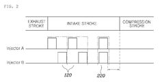
- FIG. 2 shows a simultaneous injection 220 after the individual injection 120 of the injectors 20.
- the controller 40 may make the injectors 20 alternately perform multiple times of fuel injection in the individual injection step (S200).
- the controller 40 may control each of the injectors 20 to make the injectors 20 individually inject fuel at different times. Specifically, the controller 40 may make the injectors 20 alternately perform fuel injection multiple times so as to induce a swirling effect.
- FIG. 2 shows an example in which a fuel injection section is set in such a way that a pair of injectors 20 alternately inject fuel.
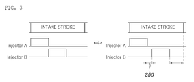
- the controller 40 may control the fuel injection sections of the injectors 20 to form a delay section 250, during which fuel injection may not be performed, in the interval between the fuel injection sections of the injectors 20 in the individual injection step (S200).
- the flow of the fuel injected by each of the injectors 20 may induce swirling in the combustion chamber 10 in the individual injection step (S200).
- an injector 20 in, or disposed in, one side and an additional injector in, or disposed in, another side consecutively inject fuel the flow of fuel injected by the injector in the one side may be disturbed by the flow of the fuel injected by the additional injector 20 in the other side, before swirling is induced in the combustion chamber 10.
- a delay section 250 may be formed in the interval between the fuel injection sections of the injectors 20.
- FIG. 3 shows an example in which a delay section 250 may be set in the interval between the fuel injection sections of the injectors 20.
- the controller 40 may control the injectors 20 to make a delay section 250 in the interval between the fuel injection sections of the injectors 20, whereby a sufficient time may be secured to enable the flow of fuel injected by each of the injectors 20 to swirl, thus improving the performance in, or of, mixing the fuel and air.
- the controller 40 may regulate the total amount of fuel in one combustion cycle by regulating an amount of fuel simultaneously injected by each of the injectors 20 in the simultaneous injection step (S300).
- the amount of fuel injected by the injectors 20 may be regulated in the simultaneous injection step (S300), whereby fuel may be prevented from adhering to the wall of the intake port 30 in the individual injection step (S200) and the fuel amount required for each driving section may be satisfied in order to prevent the combustion efficiency of an engine from decreasing.
- the multiple injectors 20 may be arranged on the intake port 30 of the engine, and the controller 40 may control the multiple injectors 20 to perform first fuel injection in a state in which the intake valve arranged in the combustion chamber 10 is closed, in the individual injection step (S200).
- intake air may flow into the combustion chamber 10. Then, in a state in which the intake valve is closed, the intake air may be compressed and exploded, and an exhaust stroke may be performed.
- the fuel injected by the injectors 20 may flow into the combustion chamber 10 only if the intake valve is open.
- the injectors 20 arranged on the intake port 30 inject fuel in a state in which the intake valve is open, the fuel may flow into the combustion chamber 10 and mix with air in the combustion chamber 10. Conversely, if the injectors 20 perform the first fuel injection shortly before the intake valve opens, namely in a state in which the intake valve is closed, the fuel that has been mixed with air in the intake port 30 may flow into the combustion chamber 10 when the intake valve opens.
- the first fuel injection may be performed in a state in which the intake valve is closed, whereby a time for mixing the fuel and air may be secured before the intake stroke, and the performance in mixing the fuel and air is improved.
- a control system for a vehicle injector may include: injectors 20 arranged to inject fuel into the combustion chamber 10 of an engine; and a controller 40 arranged to determine whether it is necessary for the injectors 20 to inject fuel according to the combustion cycle of the combustion chamber 10, to control each of the injectors 20 to make the injectors 20 inject fuel at different times when determining that fuel injection is necessary, and to control each of the injectors 20 to make the injectors 20 simultaneously inject fuel after the injectors 20 inject fuel at different times.
- each of the injectors 20 may have an injection nozzle that faces the combustion chamber 10 so as to inject fuel into the combustion chamber 10.
- Each of the injectors 20 may have an injection nozzle arranged in the combustion chamber 10, and the injection nozzle may be arranged on the intake port 30 so as to inject fuel towards the intake valve.
- the controller 40 may determine whether it is necessary for the injectors 20 to inject fuel according to a combustion cycle of the combustion chamber 10, may control each of the injectors 20 to make the injectors 20 individually inject fuel at different times when determining that the fuel injection is required, and may control each of the injectors 20 to make the injectors 20 simultaneously inject fuel after the injectors 20 inject fuel at different times.
- the controller 40 may be an ECU corresponding to an engine controller 40 or a controller 40 separately arranged for controlling the injectors 20.
- the controller 40 may determine whether it is necessary for the injectors 20 to inject fuel by observing an operation condition of the combustion chamber 10. Also, when the fuel injection is required, the controller 40 may control the multiple injectors 20 to inject fuel at different times so that the injected fuel swirls in order to improve the performance in, or of, mixing the fuel and air.
- the controller 40 may make the multiple injectors 20 simultaneously inject fuel, whereby the excessive amount of fuel may be prevented from being injected when the injectors 20 individually inject fuel, and thus the fuel may be prevented from adhering to the intake port 30. Also, because the fuel amount required for one combustion cycle can be regulated by the simultaneous fuel injection, the fuel amount required for each driving section may be satisfied.
- the fuel amount required by each combustion cycle depending on the driving condition may be regulated through a simultaneous injection plan in which multiple injectors simultaneously inject fuel after the individual injection plan. Therefore, fuel efficiency may be improved and adhesion of fuel to various surfaces may be prevented.
- a delay time during which fuel injection is interrupted may be formed in an interval between injection sections of injectors, swirling may be stably induced in a combustion chamber through the individual injection plan, thus maximizing performance in mixing fuel and air.
Landscapes
- Engineering & Computer Science (AREA)
- Chemical & Material Sciences (AREA)
- Combustion & Propulsion (AREA)
- Mechanical Engineering (AREA)
- General Engineering & Computer Science (AREA)
- Electrical Control Of Air Or Fuel Supplied To Internal-Combustion Engine (AREA)
- Fuel-Injection Apparatus (AREA)
Abstract
Description
- The present disclosure relates to a control method and system for a fuel injector that supplies fuel to a vehicle engine. More particularly, the present disclosure relates to a control method and system for a fuel injector, which may effectively improve combustion efficiency and reduce harmful exhaust gasses, through an injection plan using multiple injectors.
- Various techniques pertaining to a fuel injection method, an intake control method and a structure of an intake port have been developed and have been applied to a vehicle in order to improve engine efficiency.
- Among the various techniques, as a method for improving efficiency of a vehicle engine, a method in which fuel ingredients have a constant concentration in a mixer by improving the performance of mixing air and fuel that flow into a combustion chamber has been developed, and the combustion efficiency of an engine may be increased by quickening an ignition time.
- Particularly, in order to improve the performance of mixing air and fuel, an injection variable such as the injection time or pattern of an injector may be controlled to induce swirling, whereby ignition is stimulated and combustion efficiency may be improved.
- Here, swirling indicates that intake air flowing in a combustion chamber forms eddies that rotate along a circumference of a combustion chamber. Due to the swirling intake air, the performance of mixing the intake air and fuel in the combustion chamber is improved and combustion efficiency may be improved.
- Also, when fuel is injected by the injection nozzle of an injector arranged in an intake port side, if the fuel injected by the injector adheres to the flow path of the intake port, this may adversely affect the fuel efficiency of an engine. Therefore, the prevention of the adhesion of fuel is important in improving the efficiency of an engine.
- The foregoing is intended merely to aid in the understanding of the background of the present disclosure, and is not intended to mean that the present disclosure falls within the purview of the related art that is already known to those skilled in the art.
- The present disclosure relates to a control method and system for a vehicle injector, and an object of the present disclosure is to effectively improve combustion efficiency and to reduce harmful substances of exhaust gas through an injection plan using multiple injectors.
- In order to achieve the above object, a control method for a vehicle injector according to the present disclosure may include: an injection time determination step in which a controller determines whether it is necessary for multiple injectors to inject fuel according to a combustion cycle of a combustion chamber; an individual injection step in which the controller controls each of the multiple injectors to individually inject fuel at different times when the controller determines in the injection time determination step that it is necessary for the injectors to inject fuel; and a simultaneous injection step in which the controller controls each of the injectors to simultaneously inject fuel after the injectors individually inject fuel at different times in the individual injection step.
- In the individual injection step, the controller may control each of the injectors to make the injectors alternately inject fuel multiple times.
- In the individual injection step, the controller may control a fuel injection section of each of the injectors to form a delay section, during which fuel injection is not performed, in an interval between the fuel injection sections of the injectors.
- In the simultaneous injection step, the controller may regulate a total fuel amount injected in one combustion cycle by regulating an amount of fuel injected by each of the injectors.
- In the individual injection step, the multiple injectors may be arranged on an intake port of an engine, and the controller may make the multiple injectors perform a first fuel injection in a state in which an intake valve arranged in the combustion chamber is closed.
- Meanwhile, in order to achieve the above object, a control system for a vehicle injector according to the present disclosure may include: injectors arranged to inject fuel toward a combustion chamber of an engine; and a controller for determining whether it is necessary for the injectors to inject fuel according to a combustion cycle of a combustion chamber, for controlling each of the injectors to make the injectors individually inject fuel at different times when determining that it is necessary for the injectors to inject fuel, and for controlling each of the injectors to make the injectors simultaneously inject fuel after the injectors individually inject fuel at different times.
- The above and other objects, features, and other advantages of the present disclosure will be more clearly understood from the following detailed description when taken in conjunction with the accompanying drawings, in which:
-
FIG. 1 is a flowchart of a control method for a fuel injector according to an embodiment of the present disclosure; -
FIG. 2 is a view illustrating a section in which each injector injects fuel by a control method for a fuel injector according to an embodiment of the present disclosure; -
FIG. 3 is a view illustrating a delay time made in an interval between sections in which injectors individually inject fuel in a control method for a fuel injector according to an embodiment of the present disclosure; and -
FIG. 4 is a view illustrating a control system for a fuel injector according to an embodiment of the present disclosure. - Hereinbelow, exemplary embodiments of the present disclosure will be described in detail with reference to the accompanying drawings.
- As illustrated in
FIGS. 1 ,2 and4 , a control method for a fuel injector according to embodiments of the present disclosure may include: an injection time determination step (S100) in which acontroller 40 may determine if it is necessary formultiple injectors 20 to inject fuel according to a combustion cycle in acombustion chamber 10; an individual injection step (S200) in which thecontroller 40 may control each of theinjectors 20 to make the injectors individually inject fuel at different times when determining in the injection time determination step (S100) that the fuel injection by theinjectors 20 is required; and a simultaneous injection step (S300) in which thecontroller 40 may control the injectors to make the injectors simultaneously inject fuel after theinjectors 20 inject fuel at different times in the individual injection step (S200). - Specifically, in the injection time determination step (S100), the
controller 40 may determine if it is necessary for themultiple injectors 20 to inject fuel according to the combustion cycle of thecombustion chamber 10. - In the present disclosure, the
controller 40 may be an ECU for controlling an engine, but anadditional controller 40 for theinjectors 20 may be arranged separately. In this case, thecontroller 40 may determine the fuel injection time by observing an engine operation condition, specifically, the combustion cycle of thecombustion chamber 10 in which theinjectors 20 are located. The exact time for fuel injection may be controlled depending on a driving condition of a vehicle. - Meanwhile, when the
controller 40 determines in the injection time determination step (S100) that it is necessary for theinjectors 20 to inject fuel, thecontroller 40 may control each of theinjectors 20 to make themultiple injectors 20 individually inject fuel at different times in the individual injection step (S200). - Accordingly, the fuel injection sections during which the respective injectors inject the fuel may not overlap each other.
- In a state in which
multiple injectors 20 are arranged in asingle combustion chamber 10, if thecontroller 40 makes themultiple injectors 20 inject fuel at different times rather than making them simultaneously inject fuel, the flow of the fuel injected by each of theinjectors 20 may not have symmetry. Accordingly, a flow deviating from the center of thecombustion chamber 10, which may be a flow that rotates along the side of thecombustion chamber 10, may be made. - Such a fuel flow may occur more easily when the
multiple injectors 20 are arranged on anintake port 30 and each of theinjectors 20 injects fuel towards the side of thecombustion chamber 10 rather than towards the center point of thecombustion chamber 10. -
FIG. 4 illustrates an example in which two intake valves may be located in asingle combustion chamber 10,injectors 20 may be arranged on anintake port 30 of each of the intake valves, and each of theinjectors 20 may be arranged to inject fuel towards the point deviated from the center of thecombustion chamber 10. - In other words, when only one
injector 20 injects fuel, the fuel flows along the side of thecombustion chamber 10 and swirling may be easily induced because the fuel flow may not be disturbed by the flow of fuel injected by anotherinjector 20. - Here, swirling indicates that intake air flowing into the
combustion chamber 10 may form eddies that rotate along the circumference of thecombustion chamber 10. Due to the swirling intake air, the performance in, or of, mixing the intake air and fuel in thecombustion chamber 10 is improved, thus increasing combustion efficiency. - Consequently, as the
multiple injectors 20 may inject fuel at different times, the flow of fuel injected by each of theinjectors 20 may rotate along the wall of thecombustion chamber 10 and swirl. As the swirling occurs, the performance in, or of, mixing air and fuel is improved and fuel efficiency is improved. - Also, an ignition time may be regulated. For example, an ignition time may be quickened by adjusting the injection pattern or injection time of each of the
injectors 20. Accordingly, the combustion section, in which combustion is performed in thecombustion chamber 10, may be timely controlled in order to satisfy the power performance required for each driving section. InFIG. 2 , theindividual injection 120 may be depicted as a section in which thecontroller 40 makes a pair ofinjectors 20 inject fuel at different times. - Meanwhile, after the
multiple injectors 20 inject fuel at different times in the individual injection step (S200), thecontroller 40 may control each of theinjectors 20 to make the multiple injectors inject fuel together in the simultaneous injection step (S300). - In the simultaneous injection step of the present disclosure, as the injectors may inject the fuel together, the fuel injection sections during which the respective injectors inject the fuel may overlap with each other. The injectors may simultaneously inject the fuel. However, even if the injectors inject the fuel at exactly the same time, when the fuel injection sections overlap each other by a degree of 70% or greater, such overlapping timing may have the effect of simultaneous fuel injection described by the present disclosure.
- During the
individual injection 120 in which each of theinjectors 20 may inject fuel for a relatively short time, it may be difficult to regulate the amount of fuel to be injected. In particular, in consideration of a fuel pressure and design of theinjectors 20, it may be difficult to satisfy more than a certain level of a fuel amount only through theindividual injection 120. - Also, in the
individual injection 120 in which initial fuel injection may be performed when the intake valve of thecombustion chamber 10 is open, if the fuel amount increases, the fuel may unnecessarily adhere to the intake valve or the wall of theintake port 30, thus reducing the fuel efficiency and/or increasing exhaust gasses. - Therefore, the
controller 40 may make theinjector 20 inject fuel through multiple phases to reduce the amount of fuel injected at a single phase, whereby the fuel may be prevented from adhering to theintake port 30. Also, because the simultaneous injection step (S300) may be performed after the individual injection phase (S200), the fuel amount required for each driving section may be satisfied. - Furthermore, after swirling is induced in the individual injection step, the swirl of the fuel flow in the combustion chamber may be disrupted in the simultaneous injection step, and this may be advantageous in improving the performance in mixing the intake air and fuel.
FIG. 2 shows asimultaneous injection 220 after theindividual injection 120 of theinjectors 20. - Meanwhile, as illustrated in
FIG. 2 , in a control method for a fuel injector according to an embodiment of the present disclosure, thecontroller 40 may make theinjectors 20 alternately perform multiple times of fuel injection in the individual injection step (S200). - As described above, the
controller 40 may control each of theinjectors 20 to make theinjectors 20 individually inject fuel at different times. Specifically, thecontroller 40 may make theinjectors 20 alternately perform fuel injection multiple times so as to induce a swirling effect. - When the
multiple injectors 20 alternately induce swirling in thecombustion chamber 10, the fuel flows may be mutually disturbed by each other. Accordingly, the performance in mixing air and fuel in thecombustion chamber 10 may be improved compared to the case in which swirling is induced by the fuel injected by aninjector 20 arranged in one side.FIG. 2 shows an example in which a fuel injection section is set in such a way that a pair ofinjectors 20 alternately inject fuel. - Meanwhile, as illustrated in
FIGS. 2 and3 , in a control method for a fuel injector according to an embodiment of the present disclosure, thecontroller 40 may control the fuel injection sections of theinjectors 20 to form adelay section 250, during which fuel injection may not be performed, in the interval between the fuel injection sections of theinjectors 20 in the individual injection step (S200). - Specifically, the flow of the fuel injected by each of the
injectors 20 may induce swirling in thecombustion chamber 10 in the individual injection step (S200). However, if aninjector 20 in, or disposed in, one side and an additional injector in, or disposed in, another side consecutively inject fuel, the flow of fuel injected by the injector in the one side may be disturbed by the flow of the fuel injected by theadditional injector 20 in the other side, before swirling is induced in thecombustion chamber 10. - Therefore, in order to ensure a sufficient time to induce swirling in the flow of fuel injected by an injector arranged in one side and to sufficiently mix the fuel and air, a
delay section 250 may be formed in the interval between the fuel injection sections of theinjectors 20.FIG. 3 shows an example in which adelay section 250 may be set in the interval between the fuel injection sections of theinjectors 20. - Consequently, the
controller 40 may control theinjectors 20 to make adelay section 250 in the interval between the fuel injection sections of theinjectors 20, whereby a sufficient time may be secured to enable the flow of fuel injected by each of theinjectors 20 to swirl, thus improving the performance in, or of, mixing the fuel and air. - Meanwhile, in a control method for a fuel injector according to an embodiment of the present disclosure, the
controller 40 may regulate the total amount of fuel in one combustion cycle by regulating an amount of fuel simultaneously injected by each of theinjectors 20 in the simultaneous injection step (S300). - As described above, in the present disclosure, the amount of fuel injected by the
injectors 20 may be regulated in the simultaneous injection step (S300), whereby fuel may be prevented from adhering to the wall of theintake port 30 in the individual injection step (S200) and the fuel amount required for each driving section may be satisfied in order to prevent the combustion efficiency of an engine from decreasing. - Meanwhile, in a control method for a fuel injector according to an embodiment of the present disclosure, the
multiple injectors 20 may be arranged on theintake port 30 of the engine, and thecontroller 40 may control themultiple injectors 20 to perform first fuel injection in a state in which the intake valve arranged in thecombustion chamber 10 is closed, in the individual injection step (S200). - In the engine, when the intake valve in the
combustion chamber 10 opens, intake air may flow into thecombustion chamber 10. Then, in a state in which the intake valve is closed, the intake air may be compressed and exploded, and an exhaust stroke may be performed. Whenmultiple injectors 20 are arranged on theintake port 30 of the engine, the fuel injected by theinjectors 20 may flow into thecombustion chamber 10 only if the intake valve is open. - Accordingly, if the
injectors 20 arranged on theintake port 30 inject fuel in a state in which the intake valve is open, the fuel may flow into thecombustion chamber 10 and mix with air in thecombustion chamber 10. Conversely, if theinjectors 20 perform the first fuel injection shortly before the intake valve opens, namely in a state in which the intake valve is closed, the fuel that has been mixed with air in theintake port 30 may flow into thecombustion chamber 10 when the intake valve opens. - In other words, in an embodiment of the present disclosure, according to fuel injection through the multiple phases, the first fuel injection may be performed in a state in which the intake valve is closed, whereby a time for mixing the fuel and air may be secured before the intake stroke, and the performance in mixing the fuel and air is improved.
- Meanwhile, as illustrated in
FIG. 4 , a control system for a vehicle injector according to an embodiment of the present disclosure may include:injectors 20 arranged to inject fuel into thecombustion chamber 10 of an engine; and acontroller 40 arranged to determine whether it is necessary for theinjectors 20 to inject fuel according to the combustion cycle of thecombustion chamber 10, to control each of theinjectors 20 to make theinjectors 20 inject fuel at different times when determining that fuel injection is necessary, and to control each of theinjectors 20 to make theinjectors 20 simultaneously inject fuel after theinjectors 20 inject fuel at different times. - Specifically, each of the
injectors 20 may have an injection nozzle that faces thecombustion chamber 10 so as to inject fuel into thecombustion chamber 10. Each of theinjectors 20 may have an injection nozzle arranged in thecombustion chamber 10, and the injection nozzle may be arranged on theintake port 30 so as to inject fuel towards the intake valve. - Meanwhile, the
controller 40 may determine whether it is necessary for theinjectors 20 to inject fuel according to a combustion cycle of thecombustion chamber 10, may control each of theinjectors 20 to make theinjectors 20 individually inject fuel at different times when determining that the fuel injection is required, and may control each of theinjectors 20 to make theinjectors 20 simultaneously inject fuel after theinjectors 20 inject fuel at different times. - As described above, the
controller 40 may be an ECU corresponding to anengine controller 40 or acontroller 40 separately arranged for controlling theinjectors 20. Thecontroller 40 may determine whether it is necessary for theinjectors 20 to inject fuel by observing an operation condition of thecombustion chamber 10. Also, when the fuel injection is required, thecontroller 40 may control themultiple injectors 20 to inject fuel at different times so that the injected fuel swirls in order to improve the performance in, or of, mixing the fuel and air. - Meanwhile, after the
multiple injectors 20 inject fuel at different times, thecontroller 40 may make themultiple injectors 20 simultaneously inject fuel, whereby the excessive amount of fuel may be prevented from being injected when theinjectors 20 individually inject fuel, and thus the fuel may be prevented from adhering to theintake port 30. Also, because the fuel amount required for one combustion cycle can be regulated by the simultaneous fuel injection, the fuel amount required for each driving section may be satisfied. - According to the above-described control method and system for a vehicle injector, through an injection plan using multiple injectors, combustion efficiency may be improved, and exhaust gases may be reduced.
- Particularly, because swirling is induced in a combustion chamber through an individual injection plan in which multiple injectors inject fuel at different times, performance in mixing the fuel and intake air may be improved and ignition may be stimulated, thus improving a combustion condition and maximizing fuel efficiency.
- Also, even if the amount of fuel injected by the individual injection plan is constant, the fuel amount required by each combustion cycle depending on the driving condition may be regulated through a simultaneous injection plan in which multiple injectors simultaneously inject fuel after the individual injection plan. Therefore, fuel efficiency may be improved and adhesion of fuel to various surfaces may be prevented.
- Meanwhile, as a delay time during which fuel injection is interrupted may be formed in an interval between injection sections of injectors, swirling may be stably induced in a combustion chamber through the individual injection plan, thus maximizing performance in mixing fuel and air.
- Although a preferred embodiment of the present disclosure has been described for illustrative purposes, those skilled in the art will appreciate that various modifications, additions and substitutions are possible, without departing from the scope and spirit of the disclosure as disclosed in the accompanying claims.
Claims (6)
- A control method for a vehicle injector, comprising:an injection time determination step in which a controller determines whether it is necessary for multiple injectors to inject fuel according to a combustion cycle of a combustion chamber;an individual injection step in which the controller controls each of the multiple injectors to individually inject fuel at different times when the controller determines in the injection time determination step that it is necessary for the injectors to inject fuel; anda simultaneous injection step in which the controller controls each of the multiple injectors to simultaneously inject fuel after the multiple injectors individually inject fuel at different times in the individual injection step.
- The control method of claim 1, wherein in the individual injection step, the controller controls each of the injectors to alternately inject fuel multiple times.
- The control method of claim 1 or 2, wherein in the individual injection step, the controller controls a fuel injection section of each of the injectors to form a delay section, during which fuel injection is not performed, in an interval between the individual and simultaneous fuel injection sections of the injectors.
- The control method of any one of claims 1 to 3, wherein in the simultaneous injection step, the controller regulates a total fuel amount injected for one combustion cycle by regulating an amount of fuel injected by each of the multiple injectors.
- The control method of any one of claims 1 to 4, wherein in the individual injection step, the multiple injectors are arranged on an intake port of an engine, and the controller makes the multiple injectors perform a first fuel injection in a state in which an intake valve arranged in the combustion chamber is closed.
- A control system for a vehicle injector, comprising:injectors arranged to inject fuel toward a combustion chamber of an engine; anda controller for determining whether it is necessary for the injectors to inject fuel according to a combustion cycle of the combustion chamber, for controlling each of the injectors to make the injectors individually inject fuel at different times when determining that it is necessary for the injectors to inject fuel, and for controlling each of the injectors to make the injectors simultaneously inject fuel after the injectors individually inject fuel at different times.
Applications Claiming Priority (1)
| Application Number | Priority Date | Filing Date | Title |
|---|---|---|---|
| KR20150177237 | 2015-12-11 |
Publications (3)
| Publication Number | Publication Date |
|---|---|
| EP3179082A2 true EP3179082A2 (en) | 2017-06-14 |
| EP3179082A3 EP3179082A3 (en) | 2017-11-29 |
| EP3179082B1 EP3179082B1 (en) | 2021-02-17 |
Family
ID=56876969
Family Applications (1)
| Application Number | Title | Priority Date | Filing Date |
|---|---|---|---|
| EP16187376.5A Not-in-force EP3179082B1 (en) | 2015-12-11 | 2016-09-06 | Control method and system for fuel injectors |
Country Status (4)
| Country | Link |
|---|---|
| US (1) | US10018141B2 (en) |
| EP (1) | EP3179082B1 (en) |
| JP (1) | JP6806483B2 (en) |
| CN (1) | CN107013349A (en) |
Cited By (1)
| Publication number | Priority date | Publication date | Assignee | Title |
|---|---|---|---|---|
| US11181052B2 (en) | 2019-09-26 | 2021-11-23 | Setaysha Technical Solutions, Llc | Air-fuel metering for internal combustion reciprocating engines |
Families Citing this family (1)
| Publication number | Priority date | Publication date | Assignee | Title |
|---|---|---|---|---|
| JP7826038B2 (en) * | 2022-02-09 | 2026-03-09 | 三菱重工エンジン&ターボチャージャ株式会社 | Engine and engine control method |
Family Cites Families (18)
| Publication number | Priority date | Publication date | Assignee | Title |
|---|---|---|---|---|
| US2228302A (en) * | 1937-07-26 | 1941-01-14 | William V Falcon | Internal combustion engine |
| US4548175A (en) * | 1983-12-05 | 1985-10-22 | Toyota Jidosha Kabushiki Kaisha | Internal combustion engine with two intake valves |
| JPS61123743A (en) * | 1984-11-16 | 1986-06-11 | Hitachi Ltd | Electronic fuel injector |
| DE3713429A1 (en) | 1987-04-22 | 1988-11-03 | Thomson Brandt Gmbh | RECORDER WITH A ROTATING HEAD DRUM |
| KR100231270B1 (en) | 1997-04-29 | 1999-12-01 | 류정열 | How to inject fuel when starting a car |
| KR100482548B1 (en) | 2001-12-06 | 2005-04-14 | 현대자동차주식회사 | A gasoline direct injection engines |
| JP3885614B2 (en) * | 2002-03-07 | 2007-02-21 | 日産自動車株式会社 | Internal combustion engine |
| US6848414B2 (en) * | 2002-08-08 | 2005-02-01 | Detroit Diesel Corporation | Injection control for a common rail fuel system |
| JP2010281333A (en) | 2006-03-29 | 2010-12-16 | Denso Corp | Fuel injection control device |
| JP4863980B2 (en) * | 2007-12-07 | 2012-01-25 | 日立オートモティブシステムズ株式会社 | Control device for spark ignition internal combustion engine |
| JP5325756B2 (en) * | 2009-12-14 | 2013-10-23 | 日立オートモティブシステムズ株式会社 | Fuel injection control device for internal combustion engine |
| DE102010029935B4 (en) * | 2010-06-10 | 2023-01-26 | Robert Bosch Gmbh | Method and device for supplying fuel in an internal combustion engine |
| JP5500102B2 (en) * | 2011-02-24 | 2014-05-21 | マツダ株式会社 | Control device for spark ignition gasoline engine |
| JP5673397B2 (en) * | 2011-07-04 | 2015-02-18 | 三菱自動車工業株式会社 | Engine control device |
| JP5541535B2 (en) * | 2011-09-13 | 2014-07-09 | 日立オートモティブシステムズ株式会社 | Fuel injection control device for internal combustion engine |
| JP2013160107A (en) | 2012-02-03 | 2013-08-19 | Hitachi Automotive Systems Ltd | Fuel injection control device |
| DE102013108187A1 (en) * | 2012-12-05 | 2014-06-05 | Hyundai Motor Company | Fuel rail for an engine with dual injectors and method of controlling the fuel rail |
| JP6361537B2 (en) * | 2015-03-17 | 2018-07-25 | 株式会社デンソー | Fuel property discrimination device |
-
2016
- 2016-07-21 JP JP2016143422A patent/JP6806483B2/en active Active
- 2016-09-06 EP EP16187376.5A patent/EP3179082B1/en not_active Not-in-force
- 2016-09-08 US US15/259,824 patent/US10018141B2/en active Active
- 2016-09-26 CN CN201610852643.8A patent/CN107013349A/en active Pending
Non-Patent Citations (1)
| Title |
|---|
| None |
Cited By (2)
| Publication number | Priority date | Publication date | Assignee | Title |
|---|---|---|---|---|
| US11181052B2 (en) | 2019-09-26 | 2021-11-23 | Setaysha Technical Solutions, Llc | Air-fuel metering for internal combustion reciprocating engines |
| US12104544B2 (en) | 2019-09-26 | 2024-10-01 | Setaysha Technical Solutions LLC | Air-fuel metering for internal combustion reciprocating engines |
Also Published As
| Publication number | Publication date |
|---|---|
| CN107013349A (en) | 2017-08-04 |
| EP3179082B1 (en) | 2021-02-17 |
| US10018141B2 (en) | 2018-07-10 |
| JP2017106434A (en) | 2017-06-15 |
| JP6806483B2 (en) | 2021-01-06 |
| US20170167429A1 (en) | 2017-06-15 |
| EP3179082A3 (en) | 2017-11-29 |
Similar Documents
| Publication | Publication Date | Title |
|---|---|---|
| CN102996272B (en) | Apparatus for and method of controlling fuel injection of internal combustion engine | |
| CN106103950B (en) | engine control unit | |
| JP2013231428A (en) | Air intake system for internal combustion engine | |
| KR20130037888A (en) | Diesel - gasoline complex engine | |
| US10018141B2 (en) | Control method and system for fuel injector | |
| US20160273475A1 (en) | Control system for spark-ignition internal combustion engine | |
| CN103635679B (en) | Control device for in-cylinder injection engine | |
| CN102667113A (en) | Fuel injection controller and internal combustion engine | |
| JP4277883B2 (en) | In-cylinder injection spark ignition internal combustion engine | |
| EP3002449B1 (en) | Fuel injection valve | |
| EP2497920A2 (en) | Internal combustion engine | |
| JP6206151B2 (en) | Fuel injection control device for internal combustion engine | |
| US10808668B2 (en) | Methods and systems for a fuel injector | |
| JP2009041531A (en) | In-cylinder internal combustion engine | |
| JP2004245204A (en) | Fuel injection device for internal combustion engine | |
| KR20200119984A (en) | Engine and control method thereof | |
| JP3726901B2 (en) | Internal combustion engine control device and swirl generator | |
| CN102877996B (en) | Internal combustion engine | |
| JP2010038102A (en) | Spark-ignition internal combustion engine | |
| JP6098658B2 (en) | Evaporative fuel control device for internal combustion engine | |
| WO2020059176A1 (en) | Fuel injection control device and fuel injection control method | |
| EP3351783A1 (en) | Fuel injection control device | |
| JP4349332B2 (en) | Premixed compression ignition engine | |
| JP4238752B2 (en) | Control device for internal combustion engine | |
| JP2010096079A (en) | Fuel injection device of internal combustion engine |
Legal Events
| Date | Code | Title | Description |
|---|---|---|---|
| PUAI | Public reference made under article 153(3) epc to a published international application that has entered the european phase |
Free format text: ORIGINAL CODE: 0009012 |
|
| STAA | Information on the status of an ep patent application or granted ep patent |
Free format text: STATUS: THE APPLICATION HAS BEEN PUBLISHED |
|
| AK | Designated contracting states |
Kind code of ref document: A2 Designated state(s): AL AT BE BG CH CY CZ DE DK EE ES FI FR GB GR HR HU IE IS IT LI LT LU LV MC MK MT NL NO PL PT RO RS SE SI SK SM TR |
|
| AX | Request for extension of the european patent |
Extension state: BA ME |
|
| PUAL | Search report despatched |
Free format text: ORIGINAL CODE: 0009013 |
|
| AK | Designated contracting states |
Kind code of ref document: A3 Designated state(s): AL AT BE BG CH CY CZ DE DK EE ES FI FR GB GR HR HU IE IS IT LI LT LU LV MC MK MT NL NO PL PT RO RS SE SI SK SM TR |
|
| AX | Request for extension of the european patent |
Extension state: BA ME |
|
| RIC1 | Information provided on ipc code assigned before grant |
Ipc: F02M 45/02 20060101ALI20171020BHEP Ipc: F02M 69/04 20060101ALN20171020BHEP Ipc: F02D 41/34 20060101ALI20171020BHEP Ipc: F02D 41/30 20060101AFI20171020BHEP Ipc: F02M 61/14 20060101ALI20171020BHEP Ipc: F02D 41/04 20060101ALN20171020BHEP |
|
| STAA | Information on the status of an ep patent application or granted ep patent |
Free format text: STATUS: REQUEST FOR EXAMINATION WAS MADE |
|
| 17P | Request for examination filed |
Effective date: 20180529 |
|
| RBV | Designated contracting states (corrected) |
Designated state(s): AL AT BE BG CH CY CZ DE DK EE ES FI FR GB GR HR HU IE IS IT LI LT LU LV MC MK MT NL NO PL PT RO RS SE SI SK SM TR |
|
| STAA | Information on the status of an ep patent application or granted ep patent |
Free format text: STATUS: EXAMINATION IS IN PROGRESS |
|
| 17Q | First examination report despatched |
Effective date: 20200123 |
|
| RIC1 | Information provided on ipc code assigned before grant |
Ipc: F02M 45/02 20060101ALI20200721BHEP Ipc: F02D 41/34 20060101ALI20200721BHEP Ipc: F02D 41/30 20060101AFI20200721BHEP Ipc: F02M 69/04 20060101ALN20200721BHEP Ipc: F02D 41/04 20060101ALN20200721BHEP Ipc: F02M 61/14 20060101ALI20200721BHEP |
|
| GRAP | Despatch of communication of intention to grant a patent |
Free format text: ORIGINAL CODE: EPIDOSNIGR1 |
|
| STAA | Information on the status of an ep patent application or granted ep patent |
Free format text: STATUS: GRANT OF PATENT IS INTENDED |
|
| INTG | Intention to grant announced |
Effective date: 20200910 |
|
| RAP1 | Party data changed (applicant data changed or rights of an application transferred) |
Owner name: KIA MOTORS CORPORATION Owner name: HYUNDAI MOTOR COMPANY |
|
| GRAS | Grant fee paid |
Free format text: ORIGINAL CODE: EPIDOSNIGR3 |
|
| GRAA | (expected) grant |
Free format text: ORIGINAL CODE: 0009210 |
|
| STAA | Information on the status of an ep patent application or granted ep patent |
Free format text: STATUS: THE PATENT HAS BEEN GRANTED |
|
| AK | Designated contracting states |
Kind code of ref document: B1 Designated state(s): AL AT BE BG CH CY CZ DE DK EE ES FI FR GB GR HR HU IE IS IT LI LT LU LV MC MK MT NL NO PL PT RO RS SE SI SK SM TR |
|
| REG | Reference to a national code |
Ref country code: GB Ref legal event code: FG4D |
|
| REG | Reference to a national code |
Ref country code: CH Ref legal event code: EP |
|
| REG | Reference to a national code |
Ref country code: DE Ref legal event code: R096 Ref document number: 602016052484 Country of ref document: DE |
|
| REG | Reference to a national code |
Ref country code: AT Ref legal event code: REF Ref document number: 1361796 Country of ref document: AT Kind code of ref document: T Effective date: 20210315 |
|
| REG | Reference to a national code |
Ref country code: IE Ref legal event code: FG4D |
|
| REG | Reference to a national code |
Ref country code: LT Ref legal event code: MG9D |
|
| REG | Reference to a national code |
Ref country code: NL Ref legal event code: MP Effective date: 20210217 |
|
| PG25 | Lapsed in a contracting state [announced via postgrant information from national office to epo] |
Ref country code: HR Free format text: LAPSE BECAUSE OF FAILURE TO SUBMIT A TRANSLATION OF THE DESCRIPTION OR TO PAY THE FEE WITHIN THE PRESCRIBED TIME-LIMIT Effective date: 20210217 Ref country code: FI Free format text: LAPSE BECAUSE OF FAILURE TO SUBMIT A TRANSLATION OF THE DESCRIPTION OR TO PAY THE FEE WITHIN THE PRESCRIBED TIME-LIMIT Effective date: 20210217 Ref country code: GR Free format text: LAPSE BECAUSE OF FAILURE TO SUBMIT A TRANSLATION OF THE DESCRIPTION OR TO PAY THE FEE WITHIN THE PRESCRIBED TIME-LIMIT Effective date: 20210518 Ref country code: LT Free format text: LAPSE BECAUSE OF FAILURE TO SUBMIT A TRANSLATION OF THE DESCRIPTION OR TO PAY THE FEE WITHIN THE PRESCRIBED TIME-LIMIT Effective date: 20210217 Ref country code: BG Free format text: LAPSE BECAUSE OF FAILURE TO SUBMIT A TRANSLATION OF THE DESCRIPTION OR TO PAY THE FEE WITHIN THE PRESCRIBED TIME-LIMIT Effective date: 20210517 Ref country code: PT Free format text: LAPSE BECAUSE OF FAILURE TO SUBMIT A TRANSLATION OF THE DESCRIPTION OR TO PAY THE FEE WITHIN THE PRESCRIBED TIME-LIMIT Effective date: 20210617 Ref country code: NO Free format text: LAPSE BECAUSE OF FAILURE TO SUBMIT A TRANSLATION OF THE DESCRIPTION OR TO PAY THE FEE WITHIN THE PRESCRIBED TIME-LIMIT Effective date: 20210517 |
|
| REG | Reference to a national code |
Ref country code: AT Ref legal event code: MK05 Ref document number: 1361796 Country of ref document: AT Kind code of ref document: T Effective date: 20210217 |
|
| PG25 | Lapsed in a contracting state [announced via postgrant information from national office to epo] |
Ref country code: SE Free format text: LAPSE BECAUSE OF FAILURE TO SUBMIT A TRANSLATION OF THE DESCRIPTION OR TO PAY THE FEE WITHIN THE PRESCRIBED TIME-LIMIT Effective date: 20210217 Ref country code: RS Free format text: LAPSE BECAUSE OF FAILURE TO SUBMIT A TRANSLATION OF THE DESCRIPTION OR TO PAY THE FEE WITHIN THE PRESCRIBED TIME-LIMIT Effective date: 20210217 Ref country code: PL Free format text: LAPSE BECAUSE OF FAILURE TO SUBMIT A TRANSLATION OF THE DESCRIPTION OR TO PAY THE FEE WITHIN THE PRESCRIBED TIME-LIMIT Effective date: 20210217 Ref country code: NL Free format text: LAPSE BECAUSE OF FAILURE TO SUBMIT A TRANSLATION OF THE DESCRIPTION OR TO PAY THE FEE WITHIN THE PRESCRIBED TIME-LIMIT Effective date: 20210217 Ref country code: LV Free format text: LAPSE BECAUSE OF FAILURE TO SUBMIT A TRANSLATION OF THE DESCRIPTION OR TO PAY THE FEE WITHIN THE PRESCRIBED TIME-LIMIT Effective date: 20210217 |
|
| PG25 | Lapsed in a contracting state [announced via postgrant information from national office to epo] |
Ref country code: IS Free format text: LAPSE BECAUSE OF FAILURE TO SUBMIT A TRANSLATION OF THE DESCRIPTION OR TO PAY THE FEE WITHIN THE PRESCRIBED TIME-LIMIT Effective date: 20210617 |
|
| PG25 | Lapsed in a contracting state [announced via postgrant information from national office to epo] |
Ref country code: SM Free format text: LAPSE BECAUSE OF FAILURE TO SUBMIT A TRANSLATION OF THE DESCRIPTION OR TO PAY THE FEE WITHIN THE PRESCRIBED TIME-LIMIT Effective date: 20210217 Ref country code: AT Free format text: LAPSE BECAUSE OF FAILURE TO SUBMIT A TRANSLATION OF THE DESCRIPTION OR TO PAY THE FEE WITHIN THE PRESCRIBED TIME-LIMIT Effective date: 20210217 Ref country code: CZ Free format text: LAPSE BECAUSE OF FAILURE TO SUBMIT A TRANSLATION OF THE DESCRIPTION OR TO PAY THE FEE WITHIN THE PRESCRIBED TIME-LIMIT Effective date: 20210217 Ref country code: EE Free format text: LAPSE BECAUSE OF FAILURE TO SUBMIT A TRANSLATION OF THE DESCRIPTION OR TO PAY THE FEE WITHIN THE PRESCRIBED TIME-LIMIT Effective date: 20210217 |
|
| REG | Reference to a national code |
Ref country code: DE Ref legal event code: R097 Ref document number: 602016052484 Country of ref document: DE |
|
| PG25 | Lapsed in a contracting state [announced via postgrant information from national office to epo] |
Ref country code: RO Free format text: LAPSE BECAUSE OF FAILURE TO SUBMIT A TRANSLATION OF THE DESCRIPTION OR TO PAY THE FEE WITHIN THE PRESCRIBED TIME-LIMIT Effective date: 20210217 Ref country code: SK Free format text: LAPSE BECAUSE OF FAILURE TO SUBMIT A TRANSLATION OF THE DESCRIPTION OR TO PAY THE FEE WITHIN THE PRESCRIBED TIME-LIMIT Effective date: 20210217 Ref country code: DK Free format text: LAPSE BECAUSE OF FAILURE TO SUBMIT A TRANSLATION OF THE DESCRIPTION OR TO PAY THE FEE WITHIN THE PRESCRIBED TIME-LIMIT Effective date: 20210217 |
|
| PLBE | No opposition filed within time limit |
Free format text: ORIGINAL CODE: 0009261 |
|
| STAA | Information on the status of an ep patent application or granted ep patent |
Free format text: STATUS: NO OPPOSITION FILED WITHIN TIME LIMIT |
|
| 26N | No opposition filed |
Effective date: 20211118 |
|
| PG25 | Lapsed in a contracting state [announced via postgrant information from national office to epo] |
Ref country code: ES Free format text: LAPSE BECAUSE OF FAILURE TO SUBMIT A TRANSLATION OF THE DESCRIPTION OR TO PAY THE FEE WITHIN THE PRESCRIBED TIME-LIMIT Effective date: 20210217 Ref country code: AL Free format text: LAPSE BECAUSE OF FAILURE TO SUBMIT A TRANSLATION OF THE DESCRIPTION OR TO PAY THE FEE WITHIN THE PRESCRIBED TIME-LIMIT Effective date: 20210217 |
|
| PG25 | Lapsed in a contracting state [announced via postgrant information from national office to epo] |
Ref country code: SI Free format text: LAPSE BECAUSE OF FAILURE TO SUBMIT A TRANSLATION OF THE DESCRIPTION OR TO PAY THE FEE WITHIN THE PRESCRIBED TIME-LIMIT Effective date: 20210217 |
|
| PG25 | Lapsed in a contracting state [announced via postgrant information from national office to epo] |
Ref country code: IT Free format text: LAPSE BECAUSE OF FAILURE TO SUBMIT A TRANSLATION OF THE DESCRIPTION OR TO PAY THE FEE WITHIN THE PRESCRIBED TIME-LIMIT Effective date: 20210217 |
|
| REG | Reference to a national code |
Ref country code: CH Ref legal event code: PL |
|
| REG | Reference to a national code |
Ref country code: BE Ref legal event code: MM Effective date: 20210930 |
|
| PG25 | Lapsed in a contracting state [announced via postgrant information from national office to epo] |
Ref country code: IS Free format text: LAPSE BECAUSE OF FAILURE TO SUBMIT A TRANSLATION OF THE DESCRIPTION OR TO PAY THE FEE WITHIN THE PRESCRIBED TIME-LIMIT Effective date: 20210617 Ref country code: MC Free format text: LAPSE BECAUSE OF FAILURE TO SUBMIT A TRANSLATION OF THE DESCRIPTION OR TO PAY THE FEE WITHIN THE PRESCRIBED TIME-LIMIT Effective date: 20210217 |
|
| PG25 | Lapsed in a contracting state [announced via postgrant information from national office to epo] |
Ref country code: LU Free format text: LAPSE BECAUSE OF NON-PAYMENT OF DUE FEES Effective date: 20210906 Ref country code: IE Free format text: LAPSE BECAUSE OF NON-PAYMENT OF DUE FEES Effective date: 20210906 Ref country code: BE Free format text: LAPSE BECAUSE OF NON-PAYMENT OF DUE FEES Effective date: 20210930 |
|
| PG25 | Lapsed in a contracting state [announced via postgrant information from national office to epo] |
Ref country code: LI Free format text: LAPSE BECAUSE OF NON-PAYMENT OF DUE FEES Effective date: 20210930 Ref country code: CH Free format text: LAPSE BECAUSE OF NON-PAYMENT OF DUE FEES Effective date: 20210930 |
|
| PGFP | Annual fee paid to national office [announced via postgrant information from national office to epo] |
Ref country code: GB Payment date: 20220822 Year of fee payment: 7 Ref country code: DE Payment date: 20220621 Year of fee payment: 7 |
|
| PGFP | Annual fee paid to national office [announced via postgrant information from national office to epo] |
Ref country code: FR Payment date: 20220822 Year of fee payment: 7 |
|
| PG25 | Lapsed in a contracting state [announced via postgrant information from national office to epo] |
Ref country code: HU Free format text: LAPSE BECAUSE OF FAILURE TO SUBMIT A TRANSLATION OF THE DESCRIPTION OR TO PAY THE FEE WITHIN THE PRESCRIBED TIME-LIMIT; INVALID AB INITIO Effective date: 20160906 |
|
| P01 | Opt-out of the competence of the unified patent court (upc) registered |
Effective date: 20230504 |
|
| PG25 | Lapsed in a contracting state [announced via postgrant information from national office to epo] |
Ref country code: CY Free format text: LAPSE BECAUSE OF FAILURE TO SUBMIT A TRANSLATION OF THE DESCRIPTION OR TO PAY THE FEE WITHIN THE PRESCRIBED TIME-LIMIT Effective date: 20210217 |
|
| REG | Reference to a national code |
Ref country code: DE Ref legal event code: R119 Ref document number: 602016052484 Country of ref document: DE |
|
| PG25 | Lapsed in a contracting state [announced via postgrant information from national office to epo] |
Ref country code: MK Free format text: LAPSE BECAUSE OF FAILURE TO SUBMIT A TRANSLATION OF THE DESCRIPTION OR TO PAY THE FEE WITHIN THE PRESCRIBED TIME-LIMIT Effective date: 20210217 |
|
| GBPC | Gb: european patent ceased through non-payment of renewal fee |
Effective date: 20230906 |
|
| PG25 | Lapsed in a contracting state [announced via postgrant information from national office to epo] |
Ref country code: TR Free format text: LAPSE BECAUSE OF FAILURE TO SUBMIT A TRANSLATION OF THE DESCRIPTION OR TO PAY THE FEE WITHIN THE PRESCRIBED TIME-LIMIT Effective date: 20210217 |
|
| PG25 | Lapsed in a contracting state [announced via postgrant information from national office to epo] |
Ref country code: GB Free format text: LAPSE BECAUSE OF NON-PAYMENT OF DUE FEES Effective date: 20230906 |
|
| PG25 | Lapsed in a contracting state [announced via postgrant information from national office to epo] |
Ref country code: GB Free format text: LAPSE BECAUSE OF NON-PAYMENT OF DUE FEES Effective date: 20230906 Ref country code: FR Free format text: LAPSE BECAUSE OF NON-PAYMENT OF DUE FEES Effective date: 20230930 Ref country code: DE Free format text: LAPSE BECAUSE OF NON-PAYMENT OF DUE FEES Effective date: 20240403 |
|
| PG25 | Lapsed in a contracting state [announced via postgrant information from national office to epo] |
Ref country code: MT Free format text: LAPSE BECAUSE OF FAILURE TO SUBMIT A TRANSLATION OF THE DESCRIPTION OR TO PAY THE FEE WITHIN THE PRESCRIBED TIME-LIMIT Effective date: 20210217 |