EP3178683A1 - Method and apparatus for controlling a compressor of a vehicle air conditioning system - Google Patents
Method and apparatus for controlling a compressor of a vehicle air conditioning system Download PDFInfo
- Publication number
- EP3178683A1 EP3178683A1 EP16175930.3A EP16175930A EP3178683A1 EP 3178683 A1 EP3178683 A1 EP 3178683A1 EP 16175930 A EP16175930 A EP 16175930A EP 3178683 A1 EP3178683 A1 EP 3178683A1
- Authority
- EP
- European Patent Office
- Prior art keywords
- operation rate
- compressor
- controller
- accelerator pedal
- external air
- Prior art date
- Legal status (The legal status is an assumption and is not a legal conclusion. Google has not performed a legal analysis and makes no representation as to the accuracy of the status listed.)
- Granted
Links
Images


Classifications
-
- B—PERFORMING OPERATIONS; TRANSPORTING
- B60—VEHICLES IN GENERAL
- B60H—ARRANGEMENTS OF HEATING, COOLING, VENTILATING OR OTHER AIR-TREATING DEVICES SPECIALLY ADAPTED FOR PASSENGER OR GOODS SPACES OF VEHICLES
- B60H1/00—Heating, cooling or ventilating devices
- B60H1/32—Cooling devices
- B60H1/3204—Cooling devices using compression
- B60H1/3205—Control means therefor
- B60H1/3208—Vehicle drive related control of the compressor drive means, e.g. for fuel saving purposes
-
- B—PERFORMING OPERATIONS; TRANSPORTING
- B60—VEHICLES IN GENERAL
- B60H—ARRANGEMENTS OF HEATING, COOLING, VENTILATING OR OTHER AIR-TREATING DEVICES SPECIALLY ADAPTED FOR PASSENGER OR GOODS SPACES OF VEHICLES
- B60H1/00—Heating, cooling or ventilating devices
- B60H1/00421—Driving arrangements for parts of a vehicle air-conditioning
- B60H1/0045—Driving arrangements for parts of a vehicle air-conditioning mechanical power take-offs from the vehicle propulsion unit
-
- B—PERFORMING OPERATIONS; TRANSPORTING
- B60—VEHICLES IN GENERAL
- B60H—ARRANGEMENTS OF HEATING, COOLING, VENTILATING OR OTHER AIR-TREATING DEVICES SPECIALLY ADAPTED FOR PASSENGER OR GOODS SPACES OF VEHICLES
- B60H1/00—Heating, cooling or ventilating devices
- B60H1/00642—Control systems or circuits; Control members or indication devices for heating, cooling or ventilating devices
- B60H1/00735—Control systems or circuits characterised by their input, i.e. by the detection, measurement or calculation of particular conditions, e.g. signal treatment, dynamic models
- B60H1/00764—Control systems or circuits characterised by their input, i.e. by the detection, measurement or calculation of particular conditions, e.g. signal treatment, dynamic models the input being a vehicle driving condition, e.g. speed
-
- B—PERFORMING OPERATIONS; TRANSPORTING
- B60—VEHICLES IN GENERAL
- B60H—ARRANGEMENTS OF HEATING, COOLING, VENTILATING OR OTHER AIR-TREATING DEVICES SPECIALLY ADAPTED FOR PASSENGER OR GOODS SPACES OF VEHICLES
- B60H1/00—Heating, cooling or ventilating devices
- B60H1/32—Cooling devices
- B60H2001/3236—Cooling devices information from a variable is obtained
- B60H2001/3255—Cooling devices information from a variable is obtained related to temperature
-
- B—PERFORMING OPERATIONS; TRANSPORTING
- B60—VEHICLES IN GENERAL
- B60H—ARRANGEMENTS OF HEATING, COOLING, VENTILATING OR OTHER AIR-TREATING DEVICES SPECIALLY ADAPTED FOR PASSENGER OR GOODS SPACES OF VEHICLES
- B60H1/00—Heating, cooling or ventilating devices
- B60H1/32—Cooling devices
- B60H2001/3236—Cooling devices information from a variable is obtained
- B60H2001/3266—Cooling devices information from a variable is obtained related to the operation of the vehicle
-
- B—PERFORMING OPERATIONS; TRANSPORTING
- B60—VEHICLES IN GENERAL
- B60H—ARRANGEMENTS OF HEATING, COOLING, VENTILATING OR OTHER AIR-TREATING DEVICES SPECIALLY ADAPTED FOR PASSENGER OR GOODS SPACES OF VEHICLES
- B60H1/00—Heating, cooling or ventilating devices
- B60H1/32—Cooling devices
- B60H2001/3269—Cooling devices output of a control signal
- B60H2001/327—Cooling devices output of a control signal related to a compressing unit
-
- B—PERFORMING OPERATIONS; TRANSPORTING
- B60—VEHICLES IN GENERAL
- B60H—ARRANGEMENTS OF HEATING, COOLING, VENTILATING OR OTHER AIR-TREATING DEVICES SPECIALLY ADAPTED FOR PASSENGER OR GOODS SPACES OF VEHICLES
- B60H1/00—Heating, cooling or ventilating devices
- B60H1/32—Cooling devices
- B60H2001/3269—Cooling devices output of a control signal
- B60H2001/327—Cooling devices output of a control signal related to a compressing unit
- B60H2001/3273—Cooling devices output of a control signal related to a compressing unit related to the operation of the vehicle, e.g. the compressor driving torque
-
- B—PERFORMING OPERATIONS; TRANSPORTING
- B60—VEHICLES IN GENERAL
- B60H—ARRANGEMENTS OF HEATING, COOLING, VENTILATING OR OTHER AIR-TREATING DEVICES SPECIALLY ADAPTED FOR PASSENGER OR GOODS SPACES OF VEHICLES
- B60H1/00—Heating, cooling or ventilating devices
- B60H1/32—Cooling devices
- B60H2001/3269—Cooling devices output of a control signal
- B60H2001/327—Cooling devices output of a control signal related to a compressing unit
- B60H2001/3275—Cooling devices output of a control signal related to a compressing unit to control the volume of a compressor
Definitions
- the present invention relates to a method and an apparatus for controlling a compressor, and more particularly, to a method and apparatus for controlling a compressor and expanding an operation range of the compressor to improve fuel efficiency of a vehicle.
- the air conditioning system includes a compressor, an evaporator, and a condenser.
- the compressor is configured to compress a refrigerant that flows in from the evaporator, and then discharge the compressed refrigerant to the condenser.
- the compressor is further configured to receive power of an engine.
- the compressor is operated by a heater controller based on an external air temperature of a vehicle. Since a substantial amount of power of the engine is consumed when a position value of an accelerator pedal is greater than or equal to a predetermined value, an engine controller stops operation of the compressor. In other words, the engine controller has a priority related to a stopping operation of the compressor.
- the heater controller is configured to operate the compressor based only the external air temperature without considering the position value of the accelerator pedal, and thus power of the engine for driving the vehicle may become insufficient.
- the present invention provides a method and an apparatus for controlling a compressor having advantages of expanding an operation range of the compressor and improving fuel efficiency of a vehicle.
- a method for controlling a compressor may include: measuring a vehicle speed, an engine speed, a position value of an accelerator pedal, and an external air temperature; comparing the vehicle speed with a predetermined speed; determining a basic operation rate of the compressor based on the engine speed and the position value of the accelerator pedal when the vehicle speed is equal to or less than the predetermined speed; determining a final operation rate of the compressor based on the external air temperature and the determined basic operation rate; and operating the compressor based on the determined final operation rate.
- the method may further include determining the basic operation rate of the compressor based on the position value of the accelerator pedal when the vehicle speed is greater than the predetermined speed.
- the basic operation rate of the compressor may be determined using a first operation rate map in which the basic operation rate based on the engine speed and the position value of the accelerator pedal may be set.
- the first operation rate map may include a plurality of sub-regions including a first sub-region, a second sub-region, and a third sub-region, and the basic operation rate of the compressor may be determined as a maximum operation rate of the compressor when the engine speed and the position value of the accelerator pedal correspond to the first sub-region.
- the basic operation rate of the compressor may be determined as a value between the maximum operation rate and a minimum operation rate of the compressor when the engine speed and the position value of the accelerator pedal correspond to the second sub-region.
- the basic operation rate of the compressor may be determined as a minimum operation rate of the compressor when the engine speed and the position value of the accelerator pedal correspond to the third sub-region.
- the determination of the final operation rate of the compressor based on the external air temperature and the determined basic operation rate may include determining whether the external air temperature is within a predetermined temperature range; and determining the final operation rate of the compressor as the determined basic operation rate when the external air temperature is within the predetermined temperature range.
- the determination of the final operation rate of the compressor based on the external air temperature and the determined basic operation rate may include: determining a correction coefficient based on the external air temperature when the external air temperature is beyond the predetermined temperature range; and determining the final operation rate of the compressor by applying the determined correction coefficient to the determined basic operation rate.
- the correction coefficient may be set to a value that increases as the external air temperature increases.
- An apparatus for controlling a compressor may include: a vehicle speed sensor configured to measure a vehicle speed; an engine speed sensor configured to measure an engine speed; an accelerator pedal position sensor configured to measure a position value of an accelerator pedal; an external air temperature sensor configured to measure an external air temperature; and a controller configured to operate the compressor based on signals of the vehicle speed sensor, the engine speed sensor, the accelerator pedal position sensor, and the external air temperature sensor.
- the controller may be configured to determine a basic operation rate of the compressor based on the engine speed and the position value of the accelerator pedal when the vehicle speed is equal to or less than a predetermined speed, may be configured to determine a final operation rate of the compressor based on the external air temperature and the determined basic operation rate, and may be configured to operate the compressor based on the determined final operation rate.
- the controller may be configured to determine the basic operation rate of the compressor based on the position value of the accelerator pedal when the vehicle speed is greater than the predetermined speed and determine the basic operation rate of the compressor using a first operation rate map in which the basic operation rate based on the engine speed and the position value of the accelerator pedal may be set.
- the first operation rate map may include a plurality of sub-regions including a first sub-region, a second sub-region, and a third sub-region, and the controller may be configured to determine the basic operation rate of the compressor as a maximum operation rate of the compressor when the engine speed and the position value of the accelerator pedal correspond to the first sub-region.
- the controller may also be configured to determine the basic operation rate of the compressor as a value between the maximum operation rate and a minimum operation rate of the compressor when the engine speed and the position value of the accelerator pedal correspond to the second sub-region.
- the controller may be configured to determine the basic operation rate of the compressor as a minimum operation rate of the compressor when the engine speed and the position value of the accelerator pedal correspond to the third sub-region.
- the controller may be configured to determine whether the external air temperature is within a predetermined temperature range, and determine the final operation rate of the compressor as the determined basic operation rate when the external air temperature is within the predetermined temperature range.
- the controller may also be configured to determine a correction coefficient based on the external air temperature when the external air temperature is beyond the predetermined temperature range, and determine the final operation rate of the compressor by applying the correction coefficient to the determined basic operation rate.
- the correction coefficient may be set to a value that increases as the external air temperature increases.
- cooling performance of an air conditioning system may be improved by expanding an operation range of the compressor.
- fuel efficiency of a vehicle may be improved by adjusting the operation rate of the compressor based on the vehicle speed, the engine speed, the position value of the accelerator pedal, and the external air temperature.
- vehicle or “vehicular” or other similar term as used herein is inclusive of motor vehicles in general such as passenger automobiles including sports utility vehicles (SUV), buses, trucks, various commercial vehicles, watercraft including a variety of boats and ships, aircraft, and the like, and includes hybrid vehicles, electric vehicles, combustion, plug-in hybrid electric vehicles, hydrogen-powered vehicles and other alternative fuel vehicles (e.g. fuels derived from resources other than petroleum).
- motor vehicles in general such as passenger automobiles including sports utility vehicles (SUV), buses, trucks, various commercial vehicles, watercraft including a variety of boats and ships, aircraft, and the like, and includes hybrid vehicles, electric vehicles, combustion, plug-in hybrid electric vehicles, hydrogen-powered vehicles and other alternative fuel vehicles (e.g. fuels derived from resources other than petroleum).
- SUV sports utility vehicles
- plug-in hybrid electric vehicles e.g. fuels derived from resources other than petroleum
- controller/control unit refers to a hardware device that includes a memory and a processor.
- the memory is configured to store the modules and the processor is specifically configured to execute said modules to perform one or more processes which are described further below.
- control logic of the present invention may be embodied as non-transitory computer readable media on a computer readable medium containing executable program instructions executed by a processor, controller/control unit or the like.
- the computer readable mediums include, but are not limited to, ROM, RAM, compact disc (CD)-ROMs, magnetic tapes, floppy disks, flash drives, smart cards and optical data storage devices.
- the computer readable recording medium can also be distributed in network coupled computer systems so that the computer readable media is stored and executed in a distributed fashion, e.g., by a telematics server or a Controller Area Network (CAN).
- a telematics server or a Controller Area Network (CAN).
- CAN Controller Area Network
- FIG. 1 is a block diagram of an apparatus for controlling a compressor according to an exemplary embodiment of the present invention.
- an apparatus for controlling a compressor according to an exemplary embodiment of the present invention may include a data detector 10 and a controller 40.
- the data detector 10 may be configured to detect data for controlling (e.g., operating) a compressor 32, and may be configured to transmit the data detected by the data detector 10 to the controller 40.
- the data detector 10 may include a vehicle speed sensor 12, an engine speed sensor 14, an accelerator pedal position sensor 16, and an external air temperature sensor 18.
- the data detector 10 may further include various sensors (e.g., a brake pedal sensor, an exhaust temperature sensor, and an oxygen sensor) configured to operate an engine 20.
- the vehicle speed sensor 12 may be configured to measure or sense a vehicle speed, and transmit a signal corresponding thereto to an engine controller 42.
- the engine speed sensor 14 may be configured to measure or sense an engine speed, and transmit a signal corresponding thereto to the engine controller 42.
- the accelerator pedal position sensor 16 may be configured to measure or sense a position value of an accelerator pedal (i.e., an engagement degree of the accelerator pedal or the amount of pressure exerted onto the pedal), and transmit a signal corresponding thereto to the engine controller 42.
- a position value of an accelerator pedal i.e., an engagement degree of the accelerator pedal or the amount of pressure exerted onto the pedal
- the external air temperature sensor 18 may be configured to measure or sense an external air temperature of a vehicle, and transmit a signal corresponding thereto to a heater controller 44.
- the engine 20 may be configured to combust a fuel to generate torque, and various engines such as a gasoline engine, a diesel engine, and a liquefied petroleum injection (LPI) engine may be used as the engine 20.
- various engines such as a gasoline engine, a diesel engine, and a liquefied petroleum injection (LPI) engine may be used as the engine 20.
- the engine 20 may then be configured to supply power to the compressor 32.
- LPI liquefied petroleum injection
- An air conditioning system 30 may be used for warming, ventilating, and cooling the cabin of the vehicle.
- the air conditioning system 30 may include the compressor 32, a condenser 34, and an evaporator 36.
- the compressor 32 may be configured to compress a refrigerant flowing in from the evaporator 36. Compressors of variable-capacity types are widely used for vehicles.
- the compressor 32 may include a pressure control valve, and pressure of the refrigerant may be adjusted by the pressure control valve. As an operation rate of the compressor 32 is increased, cooling performance may be increased.
- the condenser 34 may be configured to condense and liquefy the compressed refrigerant.
- the evaporator 36 may be configured to evaporate the liquefied refrigerant.
- Such an air conditioning system 30 is well known to a person of ordinary skill in the art, and a detailed description thereof will be omitted.
- the controller 40 may include the engine controller 42 and the heater controller 44.
- the engine controller 42 may be configured to operate the engine 20 based on the data detected by the data detector 10.
- the engine controller 42 may be implemented with one or more processors executed by a predetermined program, and the predetermined program may include a series of commands for performing each step included in a method for controlling the engine 20.
- the engine controller 42 may be connected to the heater controller 44 via in-vehicle communication (e.g., via a controller area network (CAN)).
- the engine controller 42 may be configured to transmit the vehicle speed, the engine speed, and the position value of the accelerator pedal to the heater controller 44.
- the heater controller 44 may be configured to operate the air conditioning system 30 based on the data detected by the data detector 10.
- the heater controller 44 may be configured to determine the operation rate of the compressor 32 based on the vehicle speed, the engine speed, the position value of the accelerator pedal, and the external air temperature.
- the heater controller 44 may be implemented with one or more processors executed by a predetermined program, and the predetermined program may include a series of commands for performing each step included in a method for controlling the air conditioning system 30.
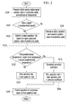
- FIG. 2 is a flowchart of a method for controlling a compressor according to an exemplary embodiment of the present invention
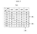
- FIG. 3 is a diagram showing a first operation rate map according to an exemplary embodiment of the present invention
- FIG. 4 is a diagram showing a second operation rate map according to an exemplary embodiment of the present invention.
- a method for controlling a compressor may begin with measuring the vehicle speed, the engine speed, the position value of the accelerator pedal, and the external air temperature at step S100 using various sensors.
- the vehicle speed sensor 12 may be configured to measure the vehicle speed
- the engine speed sensor 14 may be configured to measure the engine speed
- the accelerator pedal position sensor 16 may be configured to measure the position value of the accelerator pedal
- the external air temperature sensor 18 may be configured to measure the external air temperature.
- the controller 40 may then be configured to compare the vehicle speed with a predetermined speed at step S110.
- the predetermined speed may be set to a value to determine whether the vehicle is propelled. For example, the predetermined speed may be about 15 KPH.
- the controller 40 may be configured to determine a basic operation rate of the compressor 32 based on the engine speed and the position value of the accelerator pedal at step S120.
- the controller 40 may be configured to determine the basic operation rate of the compressor 32 using a first operation map Map1 based on the engine speed and the position value of the accelerator pedal.
- the first operation rate map Map1 shown in FIG. 3 is merely an example for describing the exemplary embodiment of the present invention, and the present invention is not limited thereto.
- the basic operation rate of the compressor 32 based on the engine speed and the position value of the accelerator pedal may be set in the first operation rate map Map1.
- the first operation rate map Map1 may include a plurality of sub-regions.
- FIG. 3 illustrates that the first operation rate map Map1 may be divided into three sub-regions SR1, SR2 and SR3, but the present invention is not limited thereto.
- the controller 40 may be configured to determine the basic operation rate of the compressor 32 as a maximum operation rate of the compressor 32.
- the maximum operation rate of the compressor 32 is 100 %.
- the controller 40 may be configured to determine the basic operation rate of the compressor 32 as a value between the maximum operation rate and a minimum operation rate of the compressor 32.
- the value between the maximum operation rate and the minimum operation rate may be about 50 % or 35 %.
- the controller 40 may be configured to determine the basic operation rate of the compressor 32 as the minimum operation rate of the compressor 32.
- the minimum operation rate of the compressor 32 is 0 %.
- the controller 40 may be configured to determine a final operation rate of the compressor 32 based on the external air temperature and the determined basic operation rate at step S130.
- the controller 40 may be configured to determine whether the external air temperature is within a predetermined temperature range at step S132.
- the controller 40 may be configured to determine whether the external air temperature is between a first predetermined temperature and a second predetermined temperature.
- the first predetermined temperature and the second predetermined temperature are reference values used to determine whether to correct the determined basic operation rate, and may be set by a person of ordinary skill in the art.
- the first predetermined temperature may be about 10 °C
- the second predetermined temperature may be about 35 °C.
- the controller 40 may be configured to determine the final operation rate of the compressor 32 as the determined basic operation rate at step S134.
- the controller 40 may be configured to determine a correction coefficient based on the external air temperature at step S 136.
- Table 1 shows an example of the correction coefficient. Table 1 is merely an example for describing the exemplary embodiment of the present invention, and the present invention is not limited thereto.
- the controller 40 may be configured to the final operation rate of the compressor 32 by applying the determined correction coefficient to the determined basic operation rate.
- the final operation rate may be calculated by multiplying the determined basic operation rate by the determined correction coefficient.
- the correction coefficient may be set to a value that increases as the external air temperature increases. Accordingly, when the external air temperature is high (i.e., high cooling performance is required), the operation rate of the compressor 32 may be increased. When the external air temperature is low (i.e., low cooling performance is required), the operation rate of the compressor 32 may be decreased.
- the final operation rate may be determined as the maximum operation rate.
- the controller 40 may then be configured to operate the compressor 32 based on the determined final operation rate at step S140.
- the controller 40 may be configured to determine the basic operation rate of the compressor 32 based on the position value of the accelerator pedal at step S150.
- the controller 40 may be configured to determine the basic operation rate of the compressor 32 using a second operation rate map Map2 based on the position value of the accelerator pedal.
- the second operation rate map Map2 shown in FIG. 4 is merely an example for describing the exemplary embodiment of the present invention, and the present invention is not limited thereto.
- the basic operation rate of the compressor 32 based on the position value of the accelerator pedal may be set in the second operation rate map Map2.
- cooling performance of the air conditioning system 30 may be improved by expanding an operation range of the compressor 32.
- fuel efficiency of the vehicle may be improved by adjusting the operation rate of the compressor 32 based on the vehicle speed, the engine speed, the position value of the accelerator pedal, and the external air temperature.
Landscapes
- Physics & Mathematics (AREA)
- Thermal Sciences (AREA)
- Engineering & Computer Science (AREA)
- Mechanical Engineering (AREA)
- Air-Conditioning For Vehicles (AREA)
- Control Of Vehicle Engines Or Engines For Specific Uses (AREA)
Abstract
Description
- This application claims priority to and the benefit of Korean Patent Application No.
10-2015-0177474 - The present invention relates to a method and an apparatus for controlling a compressor, and more particularly, to a method and apparatus for controlling a compressor and expanding an operation range of the compressor to improve fuel efficiency of a vehicle.
- Recently, exhaust regulations and fuel efficiency regulations have become more stringent to retard progress of global warming and to mitigation potential depletion of petroleum resources. To enhance fuel efficiency, improvement of auxiliary machinery such as an air conditioning system is required. The air conditioning system includes a compressor, an evaporator, and a condenser. The compressor is configured to compress a refrigerant that flows in from the evaporator, and then discharge the compressed refrigerant to the condenser. The compressor is further configured to receive power of an engine.
- According the related art, the compressor is operated by a heater controller based on an external air temperature of a vehicle. Since a substantial amount of power of the engine is consumed when a position value of an accelerator pedal is greater than or equal to a predetermined value, an engine controller stops operation of the compressor. In other words, the engine controller has a priority related to a stopping operation of the compressor.
- According to the related art, even when the external air temperature is high, the compressor may be stopped, and thus cooling performance of the air conditioning system may deteriorate. In addition, when the position value of the accelerator pedal is less than the predetermined value, the heater controller is configured to operate the compressor based only the external air temperature without considering the position value of the accelerator pedal, and thus power of the engine for driving the vehicle may become insufficient.
- The above information disclosed in this section is merely for enhancement of understanding of the background of the invention and therefore it may contain information that does not form the prior art that is already known in this country to a person of ordinary skill in the art.
- The present invention provides a method and an apparatus for controlling a compressor having advantages of expanding an operation range of the compressor and improving fuel efficiency of a vehicle.
- A method for controlling a compressor according to an exemplary embodiment of the present invention may include: measuring a vehicle speed, an engine speed, a position value of an accelerator pedal, and an external air temperature; comparing the vehicle speed with a predetermined speed; determining a basic operation rate of the compressor based on the engine speed and the position value of the accelerator pedal when the vehicle speed is equal to or less than the predetermined speed; determining a final operation rate of the compressor based on the external air temperature and the determined basic operation rate; and operating the compressor based on the determined final operation rate.
- The method may further include determining the basic operation rate of the compressor based on the position value of the accelerator pedal when the vehicle speed is greater than the predetermined speed. In the determination of the basic operation rate of the compressor based on the engine speed and the position value of the accelerator pedal when the vehicle speed is equal to or less than to the predetermined speed, the basic operation rate of the compressor may be determined using a first operation rate map in which the basic operation rate based on the engine speed and the position value of the accelerator pedal may be set.
- The first operation rate map may include a plurality of sub-regions including a first sub-region, a second sub-region, and a third sub-region, and the basic operation rate of the compressor may be determined as a maximum operation rate of the compressor when the engine speed and the position value of the accelerator pedal correspond to the first sub-region. The basic operation rate of the compressor may be determined as a value between the maximum operation rate and a minimum operation rate of the compressor when the engine speed and the position value of the accelerator pedal correspond to the second sub-region. The basic operation rate of the compressor may be determined as a minimum operation rate of the compressor when the engine speed and the position value of the accelerator pedal correspond to the third sub-region.
- Additionally, the determination of the final operation rate of the compressor based on the external air temperature and the determined basic operation rate may include determining whether the external air temperature is within a predetermined temperature range; and determining the final operation rate of the compressor as the determined basic operation rate when the external air temperature is within the predetermined temperature range.
- The determination of the final operation rate of the compressor based on the external air temperature and the determined basic operation rate may include: determining a correction coefficient based on the external air temperature when the external air temperature is beyond the predetermined temperature range; and determining the final operation rate of the compressor by applying the determined correction coefficient to the determined basic operation rate. The correction coefficient may be set to a value that increases as the external air temperature increases.
- An apparatus for controlling a compressor according to an exemplary embodiment of the present invention may include: a vehicle speed sensor configured to measure a vehicle speed; an engine speed sensor configured to measure an engine speed; an accelerator pedal position sensor configured to measure a position value of an accelerator pedal; an external air temperature sensor configured to measure an external air temperature; and a controller configured to operate the compressor based on signals of the vehicle speed sensor, the engine speed sensor, the accelerator pedal position sensor, and the external air temperature sensor.
- In particular, the controller may be configured to determine a basic operation rate of the compressor based on the engine speed and the position value of the accelerator pedal when the vehicle speed is equal to or less than a predetermined speed, may be configured to determine a final operation rate of the compressor based on the external air temperature and the determined basic operation rate, and may be configured to operate the compressor based on the determined final operation rate.
- Further, the controller may be configured to determine the basic operation rate of the compressor based on the position value of the accelerator pedal when the vehicle speed is greater than the predetermined speed and determine the basic operation rate of the compressor using a first operation rate map in which the basic operation rate based on the engine speed and the position value of the accelerator pedal may be set.
- The first operation rate map may include a plurality of sub-regions including a first sub-region, a second sub-region, and a third sub-region, and the controller may be configured to determine the basic operation rate of the compressor as a maximum operation rate of the compressor when the engine speed and the position value of the accelerator pedal correspond to the first sub-region. The controller may also be configured to determine the basic operation rate of the compressor as a value between the maximum operation rate and a minimum operation rate of the compressor when the engine speed and the position value of the accelerator pedal correspond to the second sub-region. The controller may be configured to determine the basic operation rate of the compressor as a minimum operation rate of the compressor when the engine speed and the position value of the accelerator pedal correspond to the third sub-region.
- Further, the controller may be configured to determine whether the external air temperature is within a predetermined temperature range, and determine the final operation rate of the compressor as the determined basic operation rate when the external air temperature is within the predetermined temperature range. The controller may also be configured to determine a correction coefficient based on the external air temperature when the external air temperature is beyond the predetermined temperature range, and determine the final operation rate of the compressor by applying the correction coefficient to the determined basic operation rate. The correction coefficient may be set to a value that increases as the external air temperature increases.
- According to an exemplary embodiment of the present invention, cooling performance of an air conditioning system may be improved by expanding an operation range of the compressor. In addition, fuel efficiency of a vehicle may be improved by adjusting the operation rate of the compressor based on the vehicle speed, the engine speed, the position value of the accelerator pedal, and the external air temperature.
- The above and other objects, features and other advantages of the present invention will be more clearly understood from the following detailed description when taken in conjunction with the accompanying drawings, in which:
-
FIG. 1 is a block diagram of an apparatus for controlling a compressor according to an exemplary embodiment of the present invention; -
FIG. 2 is a flowchart of a method for controlling a compressor according to an exemplary embodiment of the present invention; -
FIG. 3 is a diagram showing a first operation rate map according to an exemplary embodiment of the present invention; and -
FIG. 4 is a diagram showing a second operation rate map according to an exemplary embodiment of the present invention. -
- 10:
- data detector
- 12:
- vehicle speed sensor
- 14:
- engine speed sensor
- 16:
- accelerator pedal position sensor
- 18:
- external air temperature sensor
- 20:
- engine
- 30:
- air conditioning system
- 32:
- compressor
- 34:
- condenser
- 36:
- evaporator
- 40:
- controller
- 42:
- engine controller
- 44:
- heater controller
- It is understood that the term "vehicle" or "vehicular" or other similar term as used herein is inclusive of motor vehicles in general such as passenger automobiles including sports utility vehicles (SUV), buses, trucks, various commercial vehicles, watercraft including a variety of boats and ships, aircraft, and the like, and includes hybrid vehicles, electric vehicles, combustion, plug-in hybrid electric vehicles, hydrogen-powered vehicles and other alternative fuel vehicles (e.g. fuels derived from resources other than petroleum).
- Although exemplary embodiment is described as using a plurality of units to perform the exemplary process, it is understood that the exemplary processes may also be performed by one or plurality of modules. Additionally, it is understood that the term controller/control unit refers to a hardware device that includes a memory and a processor. The memory is configured to store the modules and the processor is specifically configured to execute said modules to perform one or more processes which are described further below.
- Furthermore, control logic of the present invention may be embodied as non-transitory computer readable media on a computer readable medium containing executable program instructions executed by a processor, controller/control unit or the like. Examples of the computer readable mediums include, but are not limited to, ROM, RAM, compact disc (CD)-ROMs, magnetic tapes, floppy disks, flash drives, smart cards and optical data storage devices. The computer readable recording medium can also be distributed in network coupled computer systems so that the computer readable media is stored and executed in a distributed fashion, e.g., by a telematics server or a Controller Area Network (CAN).
- The terminology used herein is for the purpose of describing particular embodiments only and is not intended to be limiting of the invention. As used herein, the singular forms "a", "an" and "the" are intended to include the plural forms as well, unless the context clearly indicates otherwise. It will be further understood that the terms "comprises" and/or "comprising," when used in this specification, specify the presence of stated features, integers, steps, operations, elements, and/or components, but do not preclude the presence or addition of one or more other features, integers, steps, operations, elements, components, and/or groups thereof. As used herein, the term "and/or" includes any and all combinations of one or more of the associated listed items.
- Unless specifically stated or obvious from context, as used herein, the term "about" is understood as within a range of normal tolerance in the art, for example within 2 standard deviations of the mean. "About" can be understood as within 10%, 9%, 8%, 7%, 6%, 5%, 4%, 3%, 2%, 1%, 0.5%, 0.1%, 0.05%, or 0.01% of the stated value. Unless otherwise clear from the context, all numerical values provided herein are modified by the term "about."
- Hereinafter, the present invention will be described more fully with reference to the accompanying drawings, in which exemplary embodiments of the invention are shown. However, the present invention is not limited to the exemplary embodiments which are described herein, and may modified in various different ways. Since each component shown in the drawings is arbitrarily illustrated for easy description, the present invention is not particularly limited to the components illustrated in the drawings.
-
FIG. 1 is a block diagram of an apparatus for controlling a compressor according to an exemplary embodiment of the present invention. As shown inFIG. 1 , an apparatus for controlling a compressor according to an exemplary embodiment of the present invention may include adata detector 10 and acontroller 40. - The
data detector 10 may be configured to detect data for controlling (e.g., operating) acompressor 32, and may be configured to transmit the data detected by thedata detector 10 to thecontroller 40. Thedata detector 10 may include avehicle speed sensor 12, anengine speed sensor 14, an acceleratorpedal position sensor 16, and an externalair temperature sensor 18. Thedata detector 10 may further include various sensors (e.g., a brake pedal sensor, an exhaust temperature sensor, and an oxygen sensor) configured to operate anengine 20. Particularly, thevehicle speed sensor 12 may be configured to measure or sense a vehicle speed, and transmit a signal corresponding thereto to anengine controller 42. Theengine speed sensor 14 may be configured to measure or sense an engine speed, and transmit a signal corresponding thereto to theengine controller 42. - Further, the accelerator
pedal position sensor 16 may be configured to measure or sense a position value of an accelerator pedal (i.e., an engagement degree of the accelerator pedal or the amount of pressure exerted onto the pedal), and transmit a signal corresponding thereto to theengine controller 42. When the accelerator pedal is completely engaged, the position value of the accelerator pedal is 100 %, and when the accelerator pedal is disengaged (e.g., no pressure is exerted onto the pedal), the position value of the accelerator pedal is 0 %. The externalair temperature sensor 18 may be configured to measure or sense an external air temperature of a vehicle, and transmit a signal corresponding thereto to aheater controller 44. Theengine 20 may be configured to combust a fuel to generate torque, and various engines such as a gasoline engine, a diesel engine, and a liquefied petroleum injection (LPI) engine may be used as theengine 20. Theengine 20 may then be configured to supply power to thecompressor 32. - An
air conditioning system 30 may be used for warming, ventilating, and cooling the cabin of the vehicle. Theair conditioning system 30 may include thecompressor 32, acondenser 34, and anevaporator 36. Thecompressor 32 may be configured to compress a refrigerant flowing in from theevaporator 36. Compressors of variable-capacity types are widely used for vehicles. Thecompressor 32 may include a pressure control valve, and pressure of the refrigerant may be adjusted by the pressure control valve. As an operation rate of thecompressor 32 is increased, cooling performance may be increased. Thecondenser 34 may be configured to condense and liquefy the compressed refrigerant. Theevaporator 36 may be configured to evaporate the liquefied refrigerant. Such anair conditioning system 30 is well known to a person of ordinary skill in the art, and a detailed description thereof will be omitted. - The
controller 40 may include theengine controller 42 and theheater controller 44. Theengine controller 42 may be configured to operate theengine 20 based on the data detected by thedata detector 10. For this purpose, theengine controller 42 may be implemented with one or more processors executed by a predetermined program, and the predetermined program may include a series of commands for performing each step included in a method for controlling theengine 20. Theengine controller 42 may be connected to theheater controller 44 via in-vehicle communication (e.g., via a controller area network (CAN)). Theengine controller 42 may be configured to transmit the vehicle speed, the engine speed, and the position value of the accelerator pedal to theheater controller 44. - Further, the
heater controller 44 may be configured to operate theair conditioning system 30 based on the data detected by thedata detector 10. In particular, theheater controller 44 may be configured to determine the operation rate of thecompressor 32 based on the vehicle speed, the engine speed, the position value of the accelerator pedal, and the external air temperature. For this purpose, theheater controller 44 may be implemented with one or more processors executed by a predetermined program, and the predetermined program may include a series of commands for performing each step included in a method for controlling theair conditioning system 30. - Among processes of a method for controlling a compressor according to an exemplary embodiment of the present invention, which will be described later, some processes may be performed by the
engine controller 42 and some other processes may be performed by theheater controller 44. Therefore, since a method for controlling a compressor according to an exemplary embodiment of the present invention may be described by defining theengine controller 42 and theheater controller 44 as asingle controller 40, theengine controller 42 and theheater controller 44 will be referred to as thecontroller 40 in the present specification. - Hereinafter, a method for controlling a compressor according to an exemplary embodiment of the present invention will be described in detail with reference to
FIG. 2 to FIG. 4 .FIG. 2 is a flowchart of a method for controlling a compressor according to an exemplary embodiment of the present invention,FIG. 3 is a diagram showing a first operation rate map according to an exemplary embodiment of the present invention, andFIG. 4 is a diagram showing a second operation rate map according to an exemplary embodiment of the present invention. - As shown in
FIG. 2 , a method for controlling a compressor according to an exemplary embodiment of the present invention may begin with measuring the vehicle speed, the engine speed, the position value of the accelerator pedal, and the external air temperature at step S100 using various sensors. Particularly, thevehicle speed sensor 12 may be configured to measure the vehicle speed, theengine speed sensor 14 may be configured to measure the engine speed, the acceleratorpedal position sensor 16 may be configured to measure the position value of the accelerator pedal, and the externalair temperature sensor 18 may be configured to measure the external air temperature. Thecontroller 40 may then be configured to compare the vehicle speed with a predetermined speed at step S110. The predetermined speed may be set to a value to determine whether the vehicle is propelled. For example, the predetermined speed may be about 15 KPH. - When the vehicle speed is equal to or less than the predetermined speed at step S110, the
controller 40 may be configured to determine a basic operation rate of thecompressor 32 based on the engine speed and the position value of the accelerator pedal at step S120. For example, thecontroller 40 may be configured to determine the basic operation rate of thecompressor 32 using a first operation map Map1 based on the engine speed and the position value of the accelerator pedal. The first operation rate map Map1 shown inFIG. 3 is merely an example for describing the exemplary embodiment of the present invention, and the present invention is not limited thereto. - As shown in
FIG. 3 , the basic operation rate of thecompressor 32 based on the engine speed and the position value of the accelerator pedal may be set in the first operation rate map Map1. The first operation rate map Map1 may include a plurality of sub-regions.FIG. 3 illustrates that the first operation rate map Map1 may be divided into three sub-regions SR1, SR2 and SR3, but the present invention is not limited thereto. When the engine speed and the position value of the accelerator pedal correspond to a first sub-region SR1, thecontroller 40 may be configured to determine the basic operation rate of thecompressor 32 as a maximum operation rate of thecompressor 32. The maximum operation rate of thecompressor 32 is 100 %. - When the engine speed and the position value of the accelerator pedal correspond to a second sub-region SR2, the
controller 40 may be configured to determine the basic operation rate of thecompressor 32 as a value between the maximum operation rate and a minimum operation rate of thecompressor 32. The value between the maximum operation rate and the minimum operation rate may be about 50 % or 35 %. When the engine speed and the position value of the accelerator pedal correspond to a third sub-region SR3, thecontroller 40 may be configured to determine the basic operation rate of thecompressor 32 as the minimum operation rate of thecompressor 32. The minimum operation rate of thecompressor 32 is 0 %. - Additionally, the
controller 40 may be configured to determine a final operation rate of thecompressor 32 based on the external air temperature and the determined basic operation rate at step S130. Thecontroller 40 may be configured to determine whether the external air temperature is within a predetermined temperature range at step S132. Particularly, thecontroller 40 may be configured to determine whether the external air temperature is between a first predetermined temperature and a second predetermined temperature. The first predetermined temperature and the second predetermined temperature are reference values used to determine whether to correct the determined basic operation rate, and may be set by a person of ordinary skill in the art. For example, the first predetermined temperature may be about 10 °C, and the second predetermined temperature may be about 35 °C. - When the external air temperature is within the predetermined temperature range at step S 132, the
controller 40 may be configured to determine the final operation rate of thecompressor 32 as the determined basic operation rate at step S134. When the external air temperature is beyond the predetermined temperature range at step S132, thecontroller 40 may be configured to determine a correction coefficient based on the external air temperature at step S 136. Table 1 shows an example of the correction coefficient. Table 1 is merely an example for describing the exemplary embodiment of the present invention, and the present invention is not limited thereto.Table 1 External air temperature (T) T < 10 ° C 10 °C ≤T < 20 ° C 40 °C≤T < 45 °C 45 °C≤T < 50 ° C 50 °C≤ T Correction coefficient 0.8 0.9 1.3 1.4 1.5 - Furthermore, the
controller 40 may be configured to the final operation rate of thecompressor 32 by applying the determined correction coefficient to the determined basic operation rate. Particularly, the final operation rate may be calculated by multiplying the determined basic operation rate by the determined correction coefficient. The correction coefficient may be set to a value that increases as the external air temperature increases. Accordingly, when the external air temperature is high (i.e., high cooling performance is required), the operation rate of thecompressor 32 may be increased. When the external air temperature is low (i.e., low cooling performance is required), the operation rate of thecompressor 32 may be decreased. When the determined basic operation rate is the maximum operation rate of thecompressor 32, even though the correction coefficient (e.g., 1.3, 1.4, or 1.5) is applied to the determined basic operation rate, the final operation rate may be determined as the maximum operation rate. Thecontroller 40 may then be configured to operate thecompressor 32 based on the determined final operation rate at step S140. - Meanwhile, when the vehicle speed is greater than the predetermined speed at step S110, the
controller 40 may be configured to determine the basic operation rate of thecompressor 32 based on the position value of the accelerator pedal at step S150. For example, thecontroller 40 may be configured to determine the basic operation rate of thecompressor 32 using a second operation rate map Map2 based on the position value of the accelerator pedal. The second operation rate map Map2 shown inFIG. 4 is merely an example for describing the exemplary embodiment of the present invention, and the present invention is not limited thereto. As shown inFIG. 4 , the basic operation rate of thecompressor 32 based on the position value of the accelerator pedal may be set in the second operation rate map Map2. - As described above, according to an exemplary embodiment of the present invention, cooling performance of the
air conditioning system 30 may be improved by expanding an operation range of thecompressor 32. In addition, fuel efficiency of the vehicle may be improved by adjusting the operation rate of thecompressor 32 based on the vehicle speed, the engine speed, the position value of the accelerator pedal, and the external air temperature. - While this invention has been described in connection with what is presently considered to be exemplary embodiments, it is to be understood that the invention is not limited to the disclosed exemplary embodiments, but, on the contrary, is intended to cover various modifications and equivalent arrangements included within the spirit and scope of the appended claims.
Claims (18)
- A method for controlling a compressor, comprising:measuring, by a controller, a vehicle speed, an engine speed, a position value of an accelerator pedal, and an external air temperature using various sensors;comparing, by the controller, the vehicle speed with a predetermined speed;determining, by the controller, a basic operation rate of the compressor based on the engine speed and the position value of the accelerator pedal when the vehicle speed is equal to or less than the predetermined speed;determining, by the controller, a final operation rate of the compressor based on the external air temperature and the determined basic operation rate; andoperating, by the controller, the compressor based on the determined final operation rate.
- The method of claim 1, further comprising:determining, by the controller, the basic operation rate of the compressor based on the position value of the accelerator pedal when the vehicle speed is greater than the predetermined speed.
- The method of claim 1 or 2, wherein in the determination of the basic operation rate of the compressor based on the engine speed and the position value of the accelerator pedal when the vehicle speed is equal to or less than the predetermined speed, the basic operation rate of the compressor is determined using a first operation rate map in which the basic operation rate based on the engine speed and the position value of the accelerator pedal is set.
- The method of claim 3, wherein the first operation rate map comprises a plurality of sub-regions including a first sub-region, a second sub-region, and a third sub-region, and the basic operation rate of the compressor is determined as a maximum operation rate of the compressor when the engine speed and the position value of the accelerator pedal correspond to the first sub-region.
- The method of claim any one of claims 1 to 4, wherein the basic operation rate of the compressor is determined as a value between the maximum operation rate and a minimum operation rate of the compressor when the engine speed and the position value of the accelerator pedal correspond to the second sub-region.
- The method of claim any one of claims 1 to 4, wherein the basic operation rate of the compressor is determined as a minimum operation rate of the compressor when the engine speed and the position value of the accelerator pedal correspond to the third sub-region.
- The method of any one of claims 1 to 6, wherein the determination of the final operation rate of the compressor based on the external air temperature and the determined basic operation rate comprises:determining, by the controller, whether the external air temperature is within a predetermined temperature range; anddetermining, by the controller, the final operation rate of the compressor as the determined basic operation rate when the external air temperature is within the predetermined temperature range.
- The method of claim any one of claims 1 to 7, wherein the determination of the final operation rate of the compressor based on the external air temperature and the determined basic operation rate further comprises:determining, by the controller, a correction coefficient based on the external air temperature when the external air temperature is beyond the predetermined temperature range; anddetermining, by the controller, the final operation rate of the compressor by applying the determined correction coefficient to the determined basic operation rate.
- The method of claim 8, wherein the correction coefficient is set to a value that increases as the external air temperature increases.
- An apparatus for controlling a compressor, comprising:a vehicle speed sensor configured to measure a vehicle speed;an engine speed sensor configured to measure an engine speed;an accelerator pedal position sensor configured to measure a position value of an accelerator pedal;an external air temperature sensor configured to measure an external air temperature; anda controller configured to operate the compressor based on signals of the vehicle speed sensor, the engine speed sensor, the accelerator pedal position sensor, and the external air temperature sensor,wherein the controller is configured to determine a basic operation rate of the compressor based on the engine speed and the position value of the accelerator pedal when the vehicle speed is equal to or less than a predetermined speed, determine a final operation rate of the compressor based on the external air temperature and the determined basic operation rate, and operate the compressor based on the determined final operation rate.
- The apparatus of claim 10, wherein the controller is configured to determine the basic operation rate of the compressor based on the position value of the accelerator pedal when the vehicle speed is greater than the predetermined speed.
- The apparatus of claim 10, wherein the controller is configured to determine the basic operation rate of the compressor using a first operation rate map in which the basic operation rate based on the engine speed and the position value of the accelerator pedal is set.
- The apparatus of claim 12, wherein the first operation rate map comprises a plurality of sub-regions including a first sub-region, a second sub-region, and a third sub-region, and the controller is configured to determine the basic operation rate of the compressor as a maximum operation rate of the compressor when the engine speed and the position value of the accelerator pedal correspond to the first sub-region.
- The apparatus of any one of claims 10 to 13, wherein the controller is configured to determine the basic operation rate of the compressor as a value between the maximum operation rate and a minimum operation rate when the engine speed and the position value of the accelerator pedal correspond to the second sub-region.
- The apparatus of any one of claims 10 to 13, wherein the controller is configured to determine the basic operation rate of the compressor as a minimum operation rate of the compressor when the engine speed and the position value of the accelerator pedal correspond to the third sub-region.
- The apparatus of claim any one of claims 10 to 15, wherein the controller is configured to determine whether the external air temperature is within a predetermined temperature range, and determine the final operation rate of the compressor as the determined basic operation rate when the external air temperature is within the predetermined temperature range.
- The apparatus of claims 16, wherein the controller is configured to determine a correction coefficient based on the external air temperature when the external air temperature is beyond the predetermined temperature range, and determine the final operation rate of the compressor by applying the correction coefficient to the determined basic operation rate.
- The apparatus of claim 17, wherein the correction coefficient is set to a value that increases as the external air temperature increases.
Applications Claiming Priority (1)
| Application Number | Priority Date | Filing Date | Title |
|---|---|---|---|
| KR1020150177474A KR101776744B1 (en) | 2015-12-11 | 2015-12-11 | Method and apparatus for controlling compressor |
Publications (2)
| Publication Number | Publication Date |
|---|---|
| EP3178683A1 true EP3178683A1 (en) | 2017-06-14 |
| EP3178683B1 EP3178683B1 (en) | 2021-09-01 |
Family
ID=56292472
Family Applications (1)
| Application Number | Title | Priority Date | Filing Date |
|---|---|---|---|
| EP16175930.3A Active EP3178683B1 (en) | 2015-12-11 | 2016-06-23 | Method and apparatus for controlling a compressor of a vehicle air conditioning system |
Country Status (5)
| Country | Link |
|---|---|
| US (1) | US10086678B2 (en) |
| EP (1) | EP3178683B1 (en) |
| JP (1) | JP6823396B2 (en) |
| KR (1) | KR101776744B1 (en) |
| CN (1) | CN106864213B (en) |
Families Citing this family (3)
| Publication number | Priority date | Publication date | Assignee | Title |
|---|---|---|---|---|
| KR102474376B1 (en) * | 2018-02-12 | 2022-12-05 | 현대자동차 주식회사 | Apparatus and method for controlling compressor |
| CN114506190A (en) * | 2020-11-17 | 2022-05-17 | 郑州宇通客车股份有限公司 | Air conditioner control method and system under weak vehicle power state |
| CN116771659A (en) * | 2023-06-15 | 2023-09-19 | 东风商用车有限公司 | Electric air compressor rotation speed control method and device, operation control equipment and vehicle |
Citations (3)
| Publication number | Priority date | Publication date | Assignee | Title |
|---|---|---|---|---|
| EP1700725A1 (en) * | 2005-03-11 | 2006-09-13 | Sanden Corporation | Air conditioning system for vehicles |
| DE102007030954A1 (en) * | 2006-07-06 | 2008-01-31 | Denso Corp., Kariya | Refrigerant circuit device for vehicle, has refrigerant circuit with compressor for compressing refrigerant in high temperature and high pressure refrigerant, and for discharging compressed refrigerant, and controller is also provided |
| EP1897712A2 (en) * | 2006-09-07 | 2008-03-12 | Sanden Corporation | Air-conditioning system for vehicle |
Family Cites Families (12)
| Publication number | Priority date | Publication date | Assignee | Title |
|---|---|---|---|---|
| JPS58211909A (en) * | 1982-06-03 | 1983-12-09 | Diesel Kiki Co Ltd | Cooler-mode control method of air conditioning device for vehicle |
| US6889132B2 (en) * | 2001-02-01 | 2005-05-03 | Ford Global Technologies, Llc | Vehicle drive control for 4×4 mode |
| CN100339654C (en) * | 2004-05-27 | 2007-09-26 | 三洋电机株式会社 | Engine driving type air-conditioning device |
| KR20090019622A (en) | 2007-08-21 | 2009-02-25 | 한라공조주식회사 | Control Method of Electric Compressor |
| KR101152037B1 (en) | 2009-02-13 | 2012-06-08 | 한라공조주식회사 | Method for controlling electric compressor of air conditioner for vehicle |
| US9050957B2 (en) * | 2009-02-23 | 2015-06-09 | Nabtesco Automotive Corporation | Compressed air supply system, compressed air supply device for vehicle, and method of controlling air compressor |
| JP5433387B2 (en) | 2009-11-30 | 2014-03-05 | 株式会社日立製作所 | Vehicle equipment cooling and heating system |
| KR101209724B1 (en) * | 2010-06-30 | 2012-12-07 | 기아자동차주식회사 | Device and method for controlling compressor of vehicles |
| KR101304066B1 (en) | 2010-12-06 | 2013-09-04 | 한라비스테온공조 주식회사 | Method for controlling electric compressor of air conditioner for vehicle |
| KR101326424B1 (en) | 2012-01-31 | 2013-11-11 | 쌍용자동차 주식회사 | Apparatus for controlling air conditioner of vehicle and method thereof |
| JP5959301B2 (en) * | 2012-05-16 | 2016-08-02 | 株式会社ヴァレオジャパン | Vehicle air conditioner and vehicle |
| US9989286B2 (en) * | 2013-12-17 | 2018-06-05 | Lennox Industries Inc. | Compressor operation management in air conditioners |
-
2015
- 2015-12-11 KR KR1020150177474A patent/KR101776744B1/en active Active
-
2016
- 2016-05-27 US US15/166,522 patent/US10086678B2/en active Active
- 2016-06-23 EP EP16175930.3A patent/EP3178683B1/en active Active
- 2016-07-22 JP JP2016144396A patent/JP6823396B2/en active Active
- 2016-08-23 CN CN201610709854.6A patent/CN106864213B/en active Active
Patent Citations (3)
| Publication number | Priority date | Publication date | Assignee | Title |
|---|---|---|---|---|
| EP1700725A1 (en) * | 2005-03-11 | 2006-09-13 | Sanden Corporation | Air conditioning system for vehicles |
| DE102007030954A1 (en) * | 2006-07-06 | 2008-01-31 | Denso Corp., Kariya | Refrigerant circuit device for vehicle, has refrigerant circuit with compressor for compressing refrigerant in high temperature and high pressure refrigerant, and for discharging compressed refrigerant, and controller is also provided |
| EP1897712A2 (en) * | 2006-09-07 | 2008-03-12 | Sanden Corporation | Air-conditioning system for vehicle |
Also Published As
| Publication number | Publication date |
|---|---|
| US20170166034A1 (en) | 2017-06-15 |
| JP6823396B2 (en) | 2021-02-03 |
| CN106864213B (en) | 2021-10-26 |
| US10086678B2 (en) | 2018-10-02 |
| EP3178683B1 (en) | 2021-09-01 |
| KR101776744B1 (en) | 2017-09-08 |
| KR20170069808A (en) | 2017-06-21 |
| JP2017105430A (en) | 2017-06-15 |
| CN106864213A (en) | 2017-06-20 |
Similar Documents
| Publication | Publication Date | Title |
|---|---|---|
| US9150169B2 (en) | Method and system for diagnosing failure of oil pressure sensor | |
| US9744965B2 (en) | Engine operation control system and method of eco-friendly vehicle | |
| US9809086B2 (en) | Method and system for controlling vehicle radiator flap | |
| US20160190616A1 (en) | Structure of fuel cell system and controlling method thereof | |
| US9109485B2 (en) | Method of controlling low-pressure fuel pump for GDI engine | |
| US9664586B2 (en) | System and method for compensating offset of pressure sensor | |
| US9616769B2 (en) | Torque control apparatus and method for drive motor | |
| US10464546B2 (en) | Apparatus and method for determining failure of engine clutch | |
| US9616767B2 (en) | System and method for power distribution of fuel cell hybrid vehicle | |
| US10704454B2 (en) | Control method of cooling system | |
| US9573488B2 (en) | Driving control method and system of fuel cell vehicle | |
| EP3178683B1 (en) | Method and apparatus for controlling a compressor of a vehicle air conditioning system | |
| US9541023B2 (en) | Method and system for determining causes of engine stop using ignition power monitoring | |
| US20170027022A1 (en) | Driver selection type rapid heating control method and eco vehicle thereof | |
| US9612175B2 (en) | Method and system for setting offset of oil pressure sensor | |
| US10930945B2 (en) | Fuel cell system and control method thereof | |
| US10087809B2 (en) | System and method for preventing failure of exhaust heat recovery device | |
| US10876489B2 (en) | Method and system of correcting fuel injection quantity of vehicle | |
| US20170284719A1 (en) | Compressor control apparatus and method for vehicle | |
| US20150308331A1 (en) | Engine control method for cold start stabilization | |
| US9425474B2 (en) | Method and system for controlling air intake of fuel cell vehicle | |
| US10696138B2 (en) | Control apparatus and method for compressor of vehicle | |
| US11306671B2 (en) | Method and apparatus for controlling part load mode engine torque | |
| CN106194440B (en) | Method for controlling air control valve in diesel hybrid vehicle | |
| US20220089172A1 (en) | Method and System for On-Board Diagnosis in a Vehicle |
Legal Events
| Date | Code | Title | Description |
|---|---|---|---|
| PUAI | Public reference made under article 153(3) epc to a published international application that has entered the european phase |
Free format text: ORIGINAL CODE: 0009012 |
|
| STAA | Information on the status of an ep patent application or granted ep patent |
Free format text: STATUS: THE APPLICATION HAS BEEN PUBLISHED |
|
| AK | Designated contracting states |
Kind code of ref document: A1 Designated state(s): AL AT BE BG CH CY CZ DE DK EE ES FI FR GB GR HR HU IE IS IT LI LT LU LV MC MK MT NL NO PL PT RO RS SE SI SK SM TR |
|
| AX | Request for extension of the european patent |
Extension state: BA ME |
|
| STAA | Information on the status of an ep patent application or granted ep patent |
Free format text: STATUS: REQUEST FOR EXAMINATION WAS MADE |
|
| 17P | Request for examination filed |
Effective date: 20171214 |
|
| RBV | Designated contracting states (corrected) |
Designated state(s): AL AT BE BG CH CY CZ DE DK EE ES FI FR GB GR HR HU IE IS IT LI LT LU LV MC MK MT NL NO PL PT RO RS SE SI SK SM TR |
|
| STAA | Information on the status of an ep patent application or granted ep patent |
Free format text: STATUS: EXAMINATION IS IN PROGRESS |
|
| 17Q | First examination report despatched |
Effective date: 20191210 |
|
| GRAP | Despatch of communication of intention to grant a patent |
Free format text: ORIGINAL CODE: EPIDOSNIGR1 |
|
| STAA | Information on the status of an ep patent application or granted ep patent |
Free format text: STATUS: GRANT OF PATENT IS INTENDED |
|
| INTG | Intention to grant announced |
Effective date: 20210406 |
|
| GRAS | Grant fee paid |
Free format text: ORIGINAL CODE: EPIDOSNIGR3 |
|
| GRAA | (expected) grant |
Free format text: ORIGINAL CODE: 0009210 |
|
| STAA | Information on the status of an ep patent application or granted ep patent |
Free format text: STATUS: THE PATENT HAS BEEN GRANTED |
|
| RAP3 | Party data changed (applicant data changed or rights of an application transferred) |
Owner name: KIA CORPORATION Owner name: HYUNDAI MOTOR COMPANY |
|
| AK | Designated contracting states |
Kind code of ref document: B1 Designated state(s): AL AT BE BG CH CY CZ DE DK EE ES FI FR GB GR HR HU IE IS IT LI LT LU LV MC MK MT NL NO PL PT RO RS SE SI SK SM TR |
|
| REG | Reference to a national code |
Ref country code: GB Ref legal event code: FG4D |
|
| REG | Reference to a national code |
Ref country code: CH Ref legal event code: EP Ref country code: AT Ref legal event code: REF Ref document number: 1425853 Country of ref document: AT Kind code of ref document: T Effective date: 20210915 |
|
| REG | Reference to a national code |
Ref country code: DE Ref legal event code: R096 Ref document number: 602016062972 Country of ref document: DE |
|
| REG | Reference to a national code |
Ref country code: IE Ref legal event code: FG4D |
|
| REG | Reference to a national code |
Ref country code: LT Ref legal event code: MG9D |
|
| REG | Reference to a national code |
Ref country code: NL Ref legal event code: MP Effective date: 20210901 |
|
| PG25 | Lapsed in a contracting state [announced via postgrant information from national office to epo] |
Ref country code: BG Free format text: LAPSE BECAUSE OF FAILURE TO SUBMIT A TRANSLATION OF THE DESCRIPTION OR TO PAY THE FEE WITHIN THE PRESCRIBED TIME-LIMIT Effective date: 20211201 Ref country code: LT Free format text: LAPSE BECAUSE OF FAILURE TO SUBMIT A TRANSLATION OF THE DESCRIPTION OR TO PAY THE FEE WITHIN THE PRESCRIBED TIME-LIMIT Effective date: 20210901 Ref country code: NO Free format text: LAPSE BECAUSE OF FAILURE TO SUBMIT A TRANSLATION OF THE DESCRIPTION OR TO PAY THE FEE WITHIN THE PRESCRIBED TIME-LIMIT Effective date: 20211201 Ref country code: FI Free format text: LAPSE BECAUSE OF FAILURE TO SUBMIT A TRANSLATION OF THE DESCRIPTION OR TO PAY THE FEE WITHIN THE PRESCRIBED TIME-LIMIT Effective date: 20210901 Ref country code: ES Free format text: LAPSE BECAUSE OF FAILURE TO SUBMIT A TRANSLATION OF THE DESCRIPTION OR TO PAY THE FEE WITHIN THE PRESCRIBED TIME-LIMIT Effective date: 20210901 Ref country code: RS Free format text: LAPSE BECAUSE OF FAILURE TO SUBMIT A TRANSLATION OF THE DESCRIPTION OR TO PAY THE FEE WITHIN THE PRESCRIBED TIME-LIMIT Effective date: 20210901 Ref country code: SE Free format text: LAPSE BECAUSE OF FAILURE TO SUBMIT A TRANSLATION OF THE DESCRIPTION OR TO PAY THE FEE WITHIN THE PRESCRIBED TIME-LIMIT Effective date: 20210901 Ref country code: HR Free format text: LAPSE BECAUSE OF FAILURE TO SUBMIT A TRANSLATION OF THE DESCRIPTION OR TO PAY THE FEE WITHIN THE PRESCRIBED TIME-LIMIT Effective date: 20210901 |
|
| REG | Reference to a national code |
Ref country code: AT Ref legal event code: MK05 Ref document number: 1425853 Country of ref document: AT Kind code of ref document: T Effective date: 20210901 |
|
| PG25 | Lapsed in a contracting state [announced via postgrant information from national office to epo] |
Ref country code: PL Free format text: LAPSE BECAUSE OF FAILURE TO SUBMIT A TRANSLATION OF THE DESCRIPTION OR TO PAY THE FEE WITHIN THE PRESCRIBED TIME-LIMIT Effective date: 20210901 Ref country code: LV Free format text: LAPSE BECAUSE OF FAILURE TO SUBMIT A TRANSLATION OF THE DESCRIPTION OR TO PAY THE FEE WITHIN THE PRESCRIBED TIME-LIMIT Effective date: 20210901 Ref country code: GR Free format text: LAPSE BECAUSE OF FAILURE TO SUBMIT A TRANSLATION OF THE DESCRIPTION OR TO PAY THE FEE WITHIN THE PRESCRIBED TIME-LIMIT Effective date: 20211202 |
|
| PG25 | Lapsed in a contracting state [announced via postgrant information from national office to epo] |
Ref country code: AT Free format text: LAPSE BECAUSE OF FAILURE TO SUBMIT A TRANSLATION OF THE DESCRIPTION OR TO PAY THE FEE WITHIN THE PRESCRIBED TIME-LIMIT Effective date: 20210901 |
|
| PG25 | Lapsed in a contracting state [announced via postgrant information from national office to epo] |
Ref country code: IS Free format text: LAPSE BECAUSE OF FAILURE TO SUBMIT A TRANSLATION OF THE DESCRIPTION OR TO PAY THE FEE WITHIN THE PRESCRIBED TIME-LIMIT Effective date: 20220101 Ref country code: SM Free format text: LAPSE BECAUSE OF FAILURE TO SUBMIT A TRANSLATION OF THE DESCRIPTION OR TO PAY THE FEE WITHIN THE PRESCRIBED TIME-LIMIT Effective date: 20210901 Ref country code: SK Free format text: LAPSE BECAUSE OF FAILURE TO SUBMIT A TRANSLATION OF THE DESCRIPTION OR TO PAY THE FEE WITHIN THE PRESCRIBED TIME-LIMIT Effective date: 20210901 Ref country code: RO Free format text: LAPSE BECAUSE OF FAILURE TO SUBMIT A TRANSLATION OF THE DESCRIPTION OR TO PAY THE FEE WITHIN THE PRESCRIBED TIME-LIMIT Effective date: 20210901 Ref country code: PT Free format text: LAPSE BECAUSE OF FAILURE TO SUBMIT A TRANSLATION OF THE DESCRIPTION OR TO PAY THE FEE WITHIN THE PRESCRIBED TIME-LIMIT Effective date: 20220103 Ref country code: NL Free format text: LAPSE BECAUSE OF FAILURE TO SUBMIT A TRANSLATION OF THE DESCRIPTION OR TO PAY THE FEE WITHIN THE PRESCRIBED TIME-LIMIT Effective date: 20210901 Ref country code: EE Free format text: LAPSE BECAUSE OF FAILURE TO SUBMIT A TRANSLATION OF THE DESCRIPTION OR TO PAY THE FEE WITHIN THE PRESCRIBED TIME-LIMIT Effective date: 20210901 Ref country code: CZ Free format text: LAPSE BECAUSE OF FAILURE TO SUBMIT A TRANSLATION OF THE DESCRIPTION OR TO PAY THE FEE WITHIN THE PRESCRIBED TIME-LIMIT Effective date: 20210901 Ref country code: AL Free format text: LAPSE BECAUSE OF FAILURE TO SUBMIT A TRANSLATION OF THE DESCRIPTION OR TO PAY THE FEE WITHIN THE PRESCRIBED TIME-LIMIT Effective date: 20210901 |
|
| REG | Reference to a national code |
Ref country code: DE Ref legal event code: R097 Ref document number: 602016062972 Country of ref document: DE |
|
| PLBE | No opposition filed within time limit |
Free format text: ORIGINAL CODE: 0009261 |
|
| STAA | Information on the status of an ep patent application or granted ep patent |
Free format text: STATUS: NO OPPOSITION FILED WITHIN TIME LIMIT |
|
| PG25 | Lapsed in a contracting state [announced via postgrant information from national office to epo] |
Ref country code: IT Free format text: LAPSE BECAUSE OF FAILURE TO SUBMIT A TRANSLATION OF THE DESCRIPTION OR TO PAY THE FEE WITHIN THE PRESCRIBED TIME-LIMIT Effective date: 20210901 Ref country code: DK Free format text: LAPSE BECAUSE OF FAILURE TO SUBMIT A TRANSLATION OF THE DESCRIPTION OR TO PAY THE FEE WITHIN THE PRESCRIBED TIME-LIMIT Effective date: 20210901 |
|
| 26N | No opposition filed |
Effective date: 20220602 |
|
| PG25 | Lapsed in a contracting state [announced via postgrant information from national office to epo] |
Ref country code: SI Free format text: LAPSE BECAUSE OF FAILURE TO SUBMIT A TRANSLATION OF THE DESCRIPTION OR TO PAY THE FEE WITHIN THE PRESCRIBED TIME-LIMIT Effective date: 20210901 |
|
| PG25 | Lapsed in a contracting state [announced via postgrant information from national office to epo] |
Ref country code: MC Free format text: LAPSE BECAUSE OF FAILURE TO SUBMIT A TRANSLATION OF THE DESCRIPTION OR TO PAY THE FEE WITHIN THE PRESCRIBED TIME-LIMIT Effective date: 20210901 |
|
| REG | Reference to a national code |
Ref country code: CH Ref legal event code: PL |
|
| REG | Reference to a national code |
Ref country code: BE Ref legal event code: MM Effective date: 20220630 |
|
| PG25 | Lapsed in a contracting state [announced via postgrant information from national office to epo] |
Ref country code: LU Free format text: LAPSE BECAUSE OF NON-PAYMENT OF DUE FEES Effective date: 20220623 Ref country code: LI Free format text: LAPSE BECAUSE OF NON-PAYMENT OF DUE FEES Effective date: 20220630 Ref country code: IE Free format text: LAPSE BECAUSE OF NON-PAYMENT OF DUE FEES Effective date: 20220623 Ref country code: CH Free format text: LAPSE BECAUSE OF NON-PAYMENT OF DUE FEES Effective date: 20220630 |
|
| PG25 | Lapsed in a contracting state [announced via postgrant information from national office to epo] |
Ref country code: BE Free format text: LAPSE BECAUSE OF NON-PAYMENT OF DUE FEES Effective date: 20220630 |
|
| P01 | Opt-out of the competence of the unified patent court (upc) registered |
Effective date: 20230530 |
|
| PG25 | Lapsed in a contracting state [announced via postgrant information from national office to epo] |
Ref country code: HU Free format text: LAPSE BECAUSE OF FAILURE TO SUBMIT A TRANSLATION OF THE DESCRIPTION OR TO PAY THE FEE WITHIN THE PRESCRIBED TIME-LIMIT; INVALID AB INITIO Effective date: 20160623 |
|
| PG25 | Lapsed in a contracting state [announced via postgrant information from national office to epo] |
Ref country code: MK Free format text: LAPSE BECAUSE OF FAILURE TO SUBMIT A TRANSLATION OF THE DESCRIPTION OR TO PAY THE FEE WITHIN THE PRESCRIBED TIME-LIMIT Effective date: 20210901 Ref country code: CY Free format text: LAPSE BECAUSE OF FAILURE TO SUBMIT A TRANSLATION OF THE DESCRIPTION OR TO PAY THE FEE WITHIN THE PRESCRIBED TIME-LIMIT Effective date: 20210901 |
|
| PGFP | Annual fee paid to national office [announced via postgrant information from national office to epo] |
Ref country code: GB Payment date: 20240520 Year of fee payment: 9 |
|
| PGFP | Annual fee paid to national office [announced via postgrant information from national office to epo] |
Ref country code: FR Payment date: 20240524 Year of fee payment: 9 |
|
| PG25 | Lapsed in a contracting state [announced via postgrant information from national office to epo] |
Ref country code: MT Free format text: LAPSE BECAUSE OF FAILURE TO SUBMIT A TRANSLATION OF THE DESCRIPTION OR TO PAY THE FEE WITHIN THE PRESCRIBED TIME-LIMIT Effective date: 20210901 |
|
| PGFP | Annual fee paid to national office [announced via postgrant information from national office to epo] |
Ref country code: DE Payment date: 20250520 Year of fee payment: 10 |
|
| PG25 | Lapsed in a contracting state [announced via postgrant information from national office to epo] |
Ref country code: TR Free format text: LAPSE BECAUSE OF FAILURE TO SUBMIT A TRANSLATION OF THE DESCRIPTION OR TO PAY THE FEE WITHIN THE PRESCRIBED TIME-LIMIT Effective date: 20210901 |
|
| GBPC | Gb: european patent ceased through non-payment of renewal fee |
Effective date: 20250623 |
|
| PG25 | Lapsed in a contracting state [announced via postgrant information from national office to epo] |
Ref country code: GB Free format text: LAPSE BECAUSE OF NON-PAYMENT OF DUE FEES Effective date: 20250623 |
|
| PG25 | Lapsed in a contracting state [announced via postgrant information from national office to epo] |
Ref country code: FR Free format text: LAPSE BECAUSE OF NON-PAYMENT OF DUE FEES Effective date: 20250630 |