EP3178635A1 - Method and apparatus for welding together a first object and a second object - Google Patents
Method and apparatus for welding together a first object and a second object Download PDFInfo
- Publication number
- EP3178635A1 EP3178635A1 EP15199470.4A EP15199470A EP3178635A1 EP 3178635 A1 EP3178635 A1 EP 3178635A1 EP 15199470 A EP15199470 A EP 15199470A EP 3178635 A1 EP3178635 A1 EP 3178635A1
- Authority
- EP
- European Patent Office
- Prior art keywords
- carbon nanotubes
- layer
- voltage
- contact
- temperature
- Prior art date
- Legal status (The legal status is an assumption and is not a legal conclusion. Google has not performed a legal analysis and makes no representation as to the accuracy of the status listed.)
- Granted
Links
Images



Classifications
-
- B—PERFORMING OPERATIONS; TRANSPORTING
- B29—WORKING OF PLASTICS; WORKING OF SUBSTANCES IN A PLASTIC STATE IN GENERAL
- B29C—SHAPING OR JOINING OF PLASTICS; SHAPING OF MATERIAL IN A PLASTIC STATE, NOT OTHERWISE PROVIDED FOR; AFTER-TREATMENT OF THE SHAPED PRODUCTS, e.g. REPAIRING
- B29C66/00—General aspects of processes or apparatus for joining preformed parts
- B29C66/70—General aspects of processes or apparatus for joining preformed parts characterised by the composition, physical properties or the structure of the material of the parts to be joined; Joining with non-plastics material
- B29C66/72—General aspects of processes or apparatus for joining preformed parts characterised by the composition, physical properties or the structure of the material of the parts to be joined; Joining with non-plastics material characterised by the structure of the material of the parts to be joined
- B29C66/723—General aspects of processes or apparatus for joining preformed parts characterised by the composition, physical properties or the structure of the material of the parts to be joined; Joining with non-plastics material characterised by the structure of the material of the parts to be joined being multi-layered
- B29C66/7232—General aspects of processes or apparatus for joining preformed parts characterised by the composition, physical properties or the structure of the material of the parts to be joined; Joining with non-plastics material characterised by the structure of the material of the parts to be joined being multi-layered comprising a non-plastics layer
- B29C66/72322—General aspects of processes or apparatus for joining preformed parts characterised by the composition, physical properties or the structure of the material of the parts to be joined; Joining with non-plastics material characterised by the structure of the material of the parts to be joined being multi-layered comprising a non-plastics layer consisting of elements other than metals, e.g. boron
- B29C66/72323—Carbon
-
- B—PERFORMING OPERATIONS; TRANSPORTING
- B29—WORKING OF PLASTICS; WORKING OF SUBSTANCES IN A PLASTIC STATE IN GENERAL
- B29C—SHAPING OR JOINING OF PLASTICS; SHAPING OF MATERIAL IN A PLASTIC STATE, NOT OTHERWISE PROVIDED FOR; AFTER-TREATMENT OF THE SHAPED PRODUCTS, e.g. REPAIRING
- B29C65/00—Joining or sealing of preformed parts, e.g. welding of plastics materials; Apparatus therefor
- B29C65/02—Joining or sealing of preformed parts, e.g. welding of plastics materials; Apparatus therefor by heating, with or without pressure
- B29C65/34—Joining or sealing of preformed parts, e.g. welding of plastics materials; Apparatus therefor by heating, with or without pressure using heated elements which remain in the joint, e.g. "verlorenes Schweisselement"
- B29C65/3404—Joining or sealing of preformed parts, e.g. welding of plastics materials; Apparatus therefor by heating, with or without pressure using heated elements which remain in the joint, e.g. "verlorenes Schweisselement" characterised by the type of heated elements which remain in the joint
- B29C65/3408—Joining or sealing of preformed parts, e.g. welding of plastics materials; Apparatus therefor by heating, with or without pressure using heated elements which remain in the joint, e.g. "verlorenes Schweisselement" characterised by the type of heated elements which remain in the joint comprising single particles, e.g. fillers or discontinuous fibre-reinforcements
- B29C65/3412—Joining or sealing of preformed parts, e.g. welding of plastics materials; Apparatus therefor by heating, with or without pressure using heated elements which remain in the joint, e.g. "verlorenes Schweisselement" characterised by the type of heated elements which remain in the joint comprising single particles, e.g. fillers or discontinuous fibre-reinforcements comprising fillers
-
- B—PERFORMING OPERATIONS; TRANSPORTING
- B29—WORKING OF PLASTICS; WORKING OF SUBSTANCES IN A PLASTIC STATE IN GENERAL
- B29C—SHAPING OR JOINING OF PLASTICS; SHAPING OF MATERIAL IN A PLASTIC STATE, NOT OTHERWISE PROVIDED FOR; AFTER-TREATMENT OF THE SHAPED PRODUCTS, e.g. REPAIRING
- B29C65/00—Joining or sealing of preformed parts, e.g. welding of plastics materials; Apparatus therefor
- B29C65/02—Joining or sealing of preformed parts, e.g. welding of plastics materials; Apparatus therefor by heating, with or without pressure
- B29C65/34—Joining or sealing of preformed parts, e.g. welding of plastics materials; Apparatus therefor by heating, with or without pressure using heated elements which remain in the joint, e.g. "verlorenes Schweisselement"
- B29C65/3404—Joining or sealing of preformed parts, e.g. welding of plastics materials; Apparatus therefor by heating, with or without pressure using heated elements which remain in the joint, e.g. "verlorenes Schweisselement" characterised by the type of heated elements which remain in the joint
- B29C65/344—Joining or sealing of preformed parts, e.g. welding of plastics materials; Apparatus therefor by heating, with or without pressure using heated elements which remain in the joint, e.g. "verlorenes Schweisselement" characterised by the type of heated elements which remain in the joint being a woven or non-woven fabric or being a mesh
-
- B—PERFORMING OPERATIONS; TRANSPORTING
- B29—WORKING OF PLASTICS; WORKING OF SUBSTANCES IN A PLASTIC STATE IN GENERAL
- B29C—SHAPING OR JOINING OF PLASTICS; SHAPING OF MATERIAL IN A PLASTIC STATE, NOT OTHERWISE PROVIDED FOR; AFTER-TREATMENT OF THE SHAPED PRODUCTS, e.g. REPAIRING
- B29C65/00—Joining or sealing of preformed parts, e.g. welding of plastics materials; Apparatus therefor
- B29C65/02—Joining or sealing of preformed parts, e.g. welding of plastics materials; Apparatus therefor by heating, with or without pressure
- B29C65/34—Joining or sealing of preformed parts, e.g. welding of plastics materials; Apparatus therefor by heating, with or without pressure using heated elements which remain in the joint, e.g. "verlorenes Schweisselement"
- B29C65/3404—Joining or sealing of preformed parts, e.g. welding of plastics materials; Apparatus therefor by heating, with or without pressure using heated elements which remain in the joint, e.g. "verlorenes Schweisselement" characterised by the type of heated elements which remain in the joint
- B29C65/3456—Joining or sealing of preformed parts, e.g. welding of plastics materials; Apparatus therefor by heating, with or without pressure using heated elements which remain in the joint, e.g. "verlorenes Schweisselement" characterised by the type of heated elements which remain in the joint being a layer of a multilayer part to be joined, e.g. for joining plastic-metal laminates
-
- B—PERFORMING OPERATIONS; TRANSPORTING
- B29—WORKING OF PLASTICS; WORKING OF SUBSTANCES IN A PLASTIC STATE IN GENERAL
- B29C—SHAPING OR JOINING OF PLASTICS; SHAPING OF MATERIAL IN A PLASTIC STATE, NOT OTHERWISE PROVIDED FOR; AFTER-TREATMENT OF THE SHAPED PRODUCTS, e.g. REPAIRING
- B29C65/00—Joining or sealing of preformed parts, e.g. welding of plastics materials; Apparatus therefor
- B29C65/02—Joining or sealing of preformed parts, e.g. welding of plastics materials; Apparatus therefor by heating, with or without pressure
- B29C65/34—Joining or sealing of preformed parts, e.g. welding of plastics materials; Apparatus therefor by heating, with or without pressure using heated elements which remain in the joint, e.g. "verlorenes Schweisselement"
- B29C65/3472—Joining or sealing of preformed parts, e.g. welding of plastics materials; Apparatus therefor by heating, with or without pressure using heated elements which remain in the joint, e.g. "verlorenes Schweisselement" characterised by the composition of the heated elements which remain in the joint
- B29C65/3484—Joining or sealing of preformed parts, e.g. welding of plastics materials; Apparatus therefor by heating, with or without pressure using heated elements which remain in the joint, e.g. "verlorenes Schweisselement" characterised by the composition of the heated elements which remain in the joint being non-metallic
- B29C65/3492—Joining or sealing of preformed parts, e.g. welding of plastics materials; Apparatus therefor by heating, with or without pressure using heated elements which remain in the joint, e.g. "verlorenes Schweisselement" characterised by the composition of the heated elements which remain in the joint being non-metallic being carbon
-
- B—PERFORMING OPERATIONS; TRANSPORTING
- B29—WORKING OF PLASTICS; WORKING OF SUBSTANCES IN A PLASTIC STATE IN GENERAL
- B29C—SHAPING OR JOINING OF PLASTICS; SHAPING OF MATERIAL IN A PLASTIC STATE, NOT OTHERWISE PROVIDED FOR; AFTER-TREATMENT OF THE SHAPED PRODUCTS, e.g. REPAIRING
- B29C66/00—General aspects of processes or apparatus for joining preformed parts
- B29C66/01—General aspects dealing with the joint area or with the area to be joined
- B29C66/05—Particular design of joint configurations
- B29C66/10—Particular design of joint configurations particular design of the joint cross-sections
- B29C66/11—Joint cross-sections comprising a single joint-segment, i.e. one of the parts to be joined comprising a single joint-segment in the joint cross-section
- B29C66/112—Single lapped joints
- B29C66/1122—Single lap to lap joints, i.e. overlap joints
-
- B—PERFORMING OPERATIONS; TRANSPORTING
- B29—WORKING OF PLASTICS; WORKING OF SUBSTANCES IN A PLASTIC STATE IN GENERAL
- B29C—SHAPING OR JOINING OF PLASTICS; SHAPING OF MATERIAL IN A PLASTIC STATE, NOT OTHERWISE PROVIDED FOR; AFTER-TREATMENT OF THE SHAPED PRODUCTS, e.g. REPAIRING
- B29C66/00—General aspects of processes or apparatus for joining preformed parts
- B29C66/40—General aspects of joining substantially flat articles, e.g. plates, sheets or web-like materials; Making flat seams in tubular or hollow articles; Joining single elements to substantially flat surfaces
- B29C66/41—Joining substantially flat articles ; Making flat seams in tubular or hollow articles
- B29C66/45—Joining of substantially the whole surface of the articles
-
- B—PERFORMING OPERATIONS; TRANSPORTING
- B29—WORKING OF PLASTICS; WORKING OF SUBSTANCES IN A PLASTIC STATE IN GENERAL
- B29C—SHAPING OR JOINING OF PLASTICS; SHAPING OF MATERIAL IN A PLASTIC STATE, NOT OTHERWISE PROVIDED FOR; AFTER-TREATMENT OF THE SHAPED PRODUCTS, e.g. REPAIRING
- B29C66/00—General aspects of processes or apparatus for joining preformed parts
- B29C66/70—General aspects of processes or apparatus for joining preformed parts characterised by the composition, physical properties or the structure of the material of the parts to be joined; Joining with non-plastics material
- B29C66/72—General aspects of processes or apparatus for joining preformed parts characterised by the composition, physical properties or the structure of the material of the parts to be joined; Joining with non-plastics material characterised by the structure of the material of the parts to be joined
- B29C66/721—Fibre-reinforced materials
- B29C66/7212—Fibre-reinforced materials characterised by the composition of the fibres
-
- B—PERFORMING OPERATIONS; TRANSPORTING
- B29—WORKING OF PLASTICS; WORKING OF SUBSTANCES IN A PLASTIC STATE IN GENERAL
- B29C—SHAPING OR JOINING OF PLASTICS; SHAPING OF MATERIAL IN A PLASTIC STATE, NOT OTHERWISE PROVIDED FOR; AFTER-TREATMENT OF THE SHAPED PRODUCTS, e.g. REPAIRING
- B29C66/00—General aspects of processes or apparatus for joining preformed parts
- B29C66/70—General aspects of processes or apparatus for joining preformed parts characterised by the composition, physical properties or the structure of the material of the parts to be joined; Joining with non-plastics material
- B29C66/73—General aspects of processes or apparatus for joining preformed parts characterised by the composition, physical properties or the structure of the material of the parts to be joined; Joining with non-plastics material characterised by the intensive physical properties of the material of the parts to be joined, by the optical properties of the material of the parts to be joined, by the extensive physical properties of the parts to be joined, by the state of the material of the parts to be joined or by the material of the parts to be joined being a thermoplastic or a thermoset
- B29C66/739—General aspects of processes or apparatus for joining preformed parts characterised by the composition, physical properties or the structure of the material of the parts to be joined; Joining with non-plastics material characterised by the intensive physical properties of the material of the parts to be joined, by the optical properties of the material of the parts to be joined, by the extensive physical properties of the parts to be joined, by the state of the material of the parts to be joined or by the material of the parts to be joined being a thermoplastic or a thermoset characterised by the material of the parts to be joined being a thermoplastic or a thermoset
- B29C66/7392—General aspects of processes or apparatus for joining preformed parts characterised by the composition, physical properties or the structure of the material of the parts to be joined; Joining with non-plastics material characterised by the intensive physical properties of the material of the parts to be joined, by the optical properties of the material of the parts to be joined, by the extensive physical properties of the parts to be joined, by the state of the material of the parts to be joined or by the material of the parts to be joined being a thermoplastic or a thermoset characterised by the material of the parts to be joined being a thermoplastic or a thermoset characterised by the material of at least one of the parts being a thermoplastic
- B29C66/73921—General aspects of processes or apparatus for joining preformed parts characterised by the composition, physical properties or the structure of the material of the parts to be joined; Joining with non-plastics material characterised by the intensive physical properties of the material of the parts to be joined, by the optical properties of the material of the parts to be joined, by the extensive physical properties of the parts to be joined, by the state of the material of the parts to be joined or by the material of the parts to be joined being a thermoplastic or a thermoset characterised by the material of the parts to be joined being a thermoplastic or a thermoset characterised by the material of at least one of the parts being a thermoplastic characterised by the materials of both parts being thermoplastics
-
- B—PERFORMING OPERATIONS; TRANSPORTING
- B29—WORKING OF PLASTICS; WORKING OF SUBSTANCES IN A PLASTIC STATE IN GENERAL
- B29C—SHAPING OR JOINING OF PLASTICS; SHAPING OF MATERIAL IN A PLASTIC STATE, NOT OTHERWISE PROVIDED FOR; AFTER-TREATMENT OF THE SHAPED PRODUCTS, e.g. REPAIRING
- B29C66/00—General aspects of processes or apparatus for joining preformed parts
- B29C66/90—Measuring or controlling the joining process
- B29C66/91—Measuring or controlling the joining process by measuring or controlling the temperature, the heat or the thermal flux
- B29C66/912—Measuring or controlling the joining process by measuring or controlling the temperature, the heat or the thermal flux by measuring the temperature, the heat or the thermal flux
- B29C66/9121—Measuring or controlling the joining process by measuring or controlling the temperature, the heat or the thermal flux by measuring the temperature, the heat or the thermal flux by measuring the temperature
- B29C66/91211—Measuring or controlling the joining process by measuring or controlling the temperature, the heat or the thermal flux by measuring the temperature, the heat or the thermal flux by measuring the temperature with special temperature measurement means or methods
- B29C66/91216—Measuring or controlling the joining process by measuring or controlling the temperature, the heat or the thermal flux by measuring the temperature, the heat or the thermal flux by measuring the temperature with special temperature measurement means or methods enabling contactless temperature measurements, e.g. using a pyrometer
-
- B—PERFORMING OPERATIONS; TRANSPORTING
- B29—WORKING OF PLASTICS; WORKING OF SUBSTANCES IN A PLASTIC STATE IN GENERAL
- B29C—SHAPING OR JOINING OF PLASTICS; SHAPING OF MATERIAL IN A PLASTIC STATE, NOT OTHERWISE PROVIDED FOR; AFTER-TREATMENT OF THE SHAPED PRODUCTS, e.g. REPAIRING
- B29C66/00—General aspects of processes or apparatus for joining preformed parts
- B29C66/90—Measuring or controlling the joining process
- B29C66/91—Measuring or controlling the joining process by measuring or controlling the temperature, the heat or the thermal flux
- B29C66/912—Measuring or controlling the joining process by measuring or controlling the temperature, the heat or the thermal flux by measuring the temperature, the heat or the thermal flux
- B29C66/9121—Measuring or controlling the joining process by measuring or controlling the temperature, the heat or the thermal flux by measuring the temperature, the heat or the thermal flux by measuring the temperature
- B29C66/91221—Measuring or controlling the joining process by measuring or controlling the temperature, the heat or the thermal flux by measuring the temperature, the heat or the thermal flux by measuring the temperature of the parts to be joined
-
- B—PERFORMING OPERATIONS; TRANSPORTING
- B29—WORKING OF PLASTICS; WORKING OF SUBSTANCES IN A PLASTIC STATE IN GENERAL
- B29C—SHAPING OR JOINING OF PLASTICS; SHAPING OF MATERIAL IN A PLASTIC STATE, NOT OTHERWISE PROVIDED FOR; AFTER-TREATMENT OF THE SHAPED PRODUCTS, e.g. REPAIRING
- B29C66/00—General aspects of processes or apparatus for joining preformed parts
- B29C66/90—Measuring or controlling the joining process
- B29C66/91—Measuring or controlling the joining process by measuring or controlling the temperature, the heat or the thermal flux
- B29C66/914—Measuring or controlling the joining process by measuring or controlling the temperature, the heat or the thermal flux by controlling or regulating the temperature, the heat or the thermal flux
- B29C66/9161—Measuring or controlling the joining process by measuring or controlling the temperature, the heat or the thermal flux by controlling or regulating the temperature, the heat or the thermal flux by controlling or regulating the heat or the thermal flux, i.e. the heat flux
- B29C66/91651—Measuring or controlling the joining process by measuring or controlling the temperature, the heat or the thermal flux by controlling or regulating the temperature, the heat or the thermal flux by controlling or regulating the heat or the thermal flux, i.e. the heat flux by controlling or regulating the heat generated by Joule heating or induction heating
- B29C66/91653—Measuring or controlling the joining process by measuring or controlling the temperature, the heat or the thermal flux by controlling or regulating the temperature, the heat or the thermal flux by controlling or regulating the heat or the thermal flux, i.e. the heat flux by controlling or regulating the heat generated by Joule heating or induction heating by controlling or regulating the voltage, i.e. the electric potential difference or electric tension
-
- B—PERFORMING OPERATIONS; TRANSPORTING
- B29—WORKING OF PLASTICS; WORKING OF SUBSTANCES IN A PLASTIC STATE IN GENERAL
- B29C—SHAPING OR JOINING OF PLASTICS; SHAPING OF MATERIAL IN A PLASTIC STATE, NOT OTHERWISE PROVIDED FOR; AFTER-TREATMENT OF THE SHAPED PRODUCTS, e.g. REPAIRING
- B29C66/00—General aspects of processes or apparatus for joining preformed parts
- B29C66/90—Measuring or controlling the joining process
- B29C66/96—Measuring or controlling the joining process characterised by the method for implementing the controlling of the joining process
- B29C66/961—Measuring or controlling the joining process characterised by the method for implementing the controlling of the joining process involving a feedback loop mechanism, e.g. comparison with a desired value
-
- B—PERFORMING OPERATIONS; TRANSPORTING
- B29—WORKING OF PLASTICS; WORKING OF SUBSTANCES IN A PLASTIC STATE IN GENERAL
- B29C—SHAPING OR JOINING OF PLASTICS; SHAPING OF MATERIAL IN A PLASTIC STATE, NOT OTHERWISE PROVIDED FOR; AFTER-TREATMENT OF THE SHAPED PRODUCTS, e.g. REPAIRING
- B29C65/00—Joining or sealing of preformed parts, e.g. welding of plastics materials; Apparatus therefor
- B29C65/02—Joining or sealing of preformed parts, e.g. welding of plastics materials; Apparatus therefor by heating, with or without pressure
- B29C65/34—Joining or sealing of preformed parts, e.g. welding of plastics materials; Apparatus therefor by heating, with or without pressure using heated elements which remain in the joint, e.g. "verlorenes Schweisselement"
- B29C65/3404—Joining or sealing of preformed parts, e.g. welding of plastics materials; Apparatus therefor by heating, with or without pressure using heated elements which remain in the joint, e.g. "verlorenes Schweisselement" characterised by the type of heated elements which remain in the joint
- B29C65/3408—Joining or sealing of preformed parts, e.g. welding of plastics materials; Apparatus therefor by heating, with or without pressure using heated elements which remain in the joint, e.g. "verlorenes Schweisselement" characterised by the type of heated elements which remain in the joint comprising single particles, e.g. fillers or discontinuous fibre-reinforcements
- B29C65/3416—Joining or sealing of preformed parts, e.g. welding of plastics materials; Apparatus therefor by heating, with or without pressure using heated elements which remain in the joint, e.g. "verlorenes Schweisselement" characterised by the type of heated elements which remain in the joint comprising single particles, e.g. fillers or discontinuous fibre-reinforcements comprising discontinuous fibre-reinforcements
-
- B—PERFORMING OPERATIONS; TRANSPORTING
- B29—WORKING OF PLASTICS; WORKING OF SUBSTANCES IN A PLASTIC STATE IN GENERAL
- B29C—SHAPING OR JOINING OF PLASTICS; SHAPING OF MATERIAL IN A PLASTIC STATE, NOT OTHERWISE PROVIDED FOR; AFTER-TREATMENT OF THE SHAPED PRODUCTS, e.g. REPAIRING
- B29C65/00—Joining or sealing of preformed parts, e.g. welding of plastics materials; Apparatus therefor
- B29C65/02—Joining or sealing of preformed parts, e.g. welding of plastics materials; Apparatus therefor by heating, with or without pressure
- B29C65/34—Joining or sealing of preformed parts, e.g. welding of plastics materials; Apparatus therefor by heating, with or without pressure using heated elements which remain in the joint, e.g. "verlorenes Schweisselement"
- B29C65/3468—Joining or sealing of preformed parts, e.g. welding of plastics materials; Apparatus therefor by heating, with or without pressure using heated elements which remain in the joint, e.g. "verlorenes Schweisselement" characterised by the means for supplying heat to said heated elements which remain in the join, e.g. special electrical connectors of windings
-
- B—PERFORMING OPERATIONS; TRANSPORTING
- B29—WORKING OF PLASTICS; WORKING OF SUBSTANCES IN A PLASTIC STATE IN GENERAL
- B29K—INDEXING SCHEME ASSOCIATED WITH SUBCLASSES B29B, B29C OR B29D, RELATING TO MOULDING MATERIALS OR TO MATERIALS FOR MOULDS, REINFORCEMENTS, FILLERS OR PREFORMED PARTS, e.g. INSERTS
- B29K2105/00—Condition, form or state of moulded material or of the material to be shaped
- B29K2105/06—Condition, form or state of moulded material or of the material to be shaped containing reinforcements, fillers or inserts
- B29K2105/16—Fillers
- B29K2105/165—Hollow fillers, e.g. microballoons or expanded particles
- B29K2105/167—Nanotubes
-
- B—PERFORMING OPERATIONS; TRANSPORTING
- B29—WORKING OF PLASTICS; WORKING OF SUBSTANCES IN A PLASTIC STATE IN GENERAL
- B29L—INDEXING SCHEME ASSOCIATED WITH SUBCLASS B29C, RELATING TO PARTICULAR ARTICLES
- B29L2031/00—Other particular articles
- B29L2031/30—Vehicles, e.g. ships or aircraft, or body parts thereof
- B29L2031/3076—Aircrafts
Definitions
- the present invention relates to a method and an apparatus for welding together a first object and a second object.
- thermoplastic CFRP carbon fiber-reinforced thermoplastic
- thermoplastic CFRP thermoplastic
- thermoplastic CFRP is recently increasingly used, e.g., in aircraft construction.
- some aspects regarding the processing of thermoplastic CFRP are still challenging.
- co-consolidation in an autoclave, i.e., a large pressurized heat oven, that consumes much energy and requires a long process time.
- Improvement has been achieved in recent years by better thermoplastic resins requiring a scaled down version of the autoclave, i.e. TP-ovens.
- Separate welding processes for thermoplastic parts have also been developed, but have not yet reached an optimum.
- thermoplastic objects typically all require external heating sources, such as: torches, infrared radiation, on ultrasonic devices applying mechanical vibrations.
- external heating sources such as: torches, infrared radiation
- known welding processes for thermoplastic objects sometimes require separate induction circuits or electrical circuits that need to be attached to the objects to be welded in order to cause heating.
- the invention is directed to the object of providing a method and an apparatus for welding together a first object and a second object, which reduces the aforementioned problems and which is simplified compared to known welding methods and apparatuses, respectively.
- the above-mentioned object is achieved by a method for welding together a first object and a second object according to claim 1.
- the above-mentioned object is further achieved by an apparatus for welding together a first object and a second object according to claim 10.
- Advantageous embodiments are defined in the dependent claims.
- a method for welding together a first object and a second object comprises applying a layer of carbon nanotubes onto a surface of the first object and bringing the first object and the second object into contact, such that the layer of carbon nanotubes on the surface of the first object is in contact with a surface of the second object.
- the method further comprises applying a voltage to the layer of carbon nanotubes, such that an electrical current flows through the layer of carbon nanotubes, wherein material of the first object adjacent to the layer of carbon nanotubes and material of the second object adjacent to the layer of carbon nanotubes is heated and melted by the electrical current and thereby welded together.
- the first object and the second object may be objects of any desired material or shape.
- the shape and/or material of the first object does not have to be identical to the shape and/or material of the second object.
- the first object and the second object may each be formed of one or a plurality of layers of carbon fiber-reinforced thermoplastic, i.e., thermoplastic carbon fiber-reinforced plastic (thermoplastic CFRP).
- thermoplastic CFRP thermoplastic carbon fiber-reinforced plastic
- Applying a layer of carbon nanotubes (CNTs) is not limited to a single layer of carbon nanotubes.
- a plurality of sub-layers of carbon nanotubes may be applied, which, in their entirety, are considered as the layer of carbon nanotubes.
- a plurality of carbon nanotubes may be stacked above each other in the layer of carbon nanotubes.
- the layer of carbon nanotubes may comprise long carbon nanotubes, which are applied in a grid-like structure.
- the layer of carbon nanotubes may be applied such that the individual carbon nanotubes overlap each other and thereby form a continuous layer of electrically interconnected carbon nanotubes.
- the surface of the first object and the surface of the second object may each be flat surfaces. Further, the surface of the first object may have a curvature, whereas the surface of the second object has a curvature corresponding to the curvature of the surface of the first object.
- the surface of the first object and the surface of the second object may be pressed together by a predefined pressure. This pressure may be maintained during the step of applying a voltage to the layer of carbon nanotubes.
- a control can be carried out, such that a predefined voltage is applied. Further, control can be carried out, such that a predefined current flows through the layer of carbon nanotubes.
- the voltage may be applied for a predefined amount of time.
- the first object and the second object may be pressed together.
- the material of the first object and/or the material of the second object may be thermoplastic material.
- the material of the first object and/or the material of the second object may be thermoplastic material used as thermoplastic resin material in the respective object made of thermoplastic CFRP.
- a cooling step may follow in order to harden the melted material.
- the method may further comprise, before the step of bringing the first object and the second object into contact, applying a further layer of carbon nanotubes onto the surface of the second object, wherein in the step of applying the voltage, the electrical current also flows through the further layer of carbon nanotubes.
- the further layer of carbon nanotubes onto the surface of the second object both surfaces that are brought into contact are provided with an associated layer of carbon nanotubes.
- the two layers of carbon nanotubes may conjoin to one layer of carbon nanotubes between the two objects.
- the carbon nanotubes in the layer of carbon nanotubes as well as the carbon nanotubes in the further layer of carbo nanotubes may be homogeneously distributed over the entire surface of the first object and/or the second object, respectively.
- the carbon nanotubes in the layer of carbon nanotubes or in the conjoined layer of carbon nanotubes may be arranged such that an electric current may flow through the layer of carbon nanotubes or through the conjoined layer of carbon nanotubes from one end of the respective layer to another, opposite end of the respective layer.
- the material of the first object and the material of the second object may be heated by remote Joule heating.
- the material of the first object and the material of the second object adjacent to the layer of carbon nanotubes may be heated such, that a current flow is generated in the carbon nanotubes of the layer of carbon nanotubes, wherein this current couples to vibrational modes of surrounding material.
- Atoms of the surrounding material may be caused to oscillate, which causes a heating of the material. In case the heating reaches a particular temperature (a melting temperature of the respective material), the material will start melting.
- At least one of the first object and the second object may comprise carbon fiber-reinforced plastic.
- the carbon fiber-reinforced plastic CFRP
- CFRP carbon fiber-reinforced plastic
- the carbon fiber-reinforced plastic may be provided in one layer or in a plurality of layers stacked upon each other.
- the carbon fiber-reinforced plastic may comprise a plurality of carbon fibers embedded in a matrix of plastic resin.
- the first object and/or the second object may each either be entirely formed of carbon fiber-reinforced plastic or comprise parts which are made of carbon fiber-reinforced plastic.
- At least the one of the first object and the second object may comprise carbon fiber-reinforced thermoplastic.
- the one of the first object and the second object may comprise CFRP having thermoplastic properties.
- the used CFRP may comprise a resin having thermoplastic properties.
- the layer of carbon nanotubes may be applied by using a solvent comprising a plurality of carbon nanotubes.
- the layer of carbon nanotubes may be applied by pouring the solvent under controlled conditions.
- the solvent may be a solvent comprising a plurality of long carbon nanotubes.
- the layer of carbon nanotubes may also be applied by spraying the solvent onto the surface of the first object. Further, other types of application of the solvent are possible, wherein the solvent is applied in a controlled manner, such that a uniform layer of solvent is achieved on the surface on the first object and, alternatively, on the surface of the second object.
- the carbon nanotubes in the layer of carbon nanotubes may be arranged in a grid-like structure.
- the individual carbon nanotubes may be arranged such that the carbon nanotubes overlap each other and thereby form an electrical connection between them.
- the carbon nanotubes in the grid may be arranged such that an electrical connection between one end of the layer of carbon nanotubes to an opposite end of the layer of carbon nanotubes is established.
- the layer of carbon nanotubes may be arranged such that the grid-like structure homogeneously covers the surface of the first object.
- the layer of carbon nanotubes may be arranged such that it extends up to at least two edges of the first object.
- the method may further comprise, during the step of applying the voltage, measuring a temperature of the material of the first object and/or of the material of the second object.
- the method may further comprise controlling the applied voltage based on the measured temperature.
- the temperature may be measured at one particular point at the first object or the second object.
- the temperature may be measured at an interface between the first object and the second object, i.e., where the first object contacts the second object.
- the temperature may be measured in the layer of carbon nanotubes.
- not only one but a plurality of temperatures may be measured.
- a two-dimensional thermal image may be generated for an entire contact surface of the first object and the second object.
- the applied voltage may be controlled such that the measured temperature remains substantially constant.
- a feedback loop may be used.
- the applied voltage may be controlled such that each measured temperature is higher than a particular threshold temperature.
- the measured temperature may be fed into a control unit in the form of an electrical signal.
- the electrical signal may be used by the control unit in order to control the applied voltage based on the measured temperature.
- a thermal camera may be used for measuring the temperature.
- the thermal camera may be used, e.g., for generating a two-dimensional thermal image.
- the two-dimensional thermal image may show a temperature distribution of the entire contact surface between the first object and the second object.
- an apparatus for welding together a first object and a second object comprises at least two contact units configured to apply a voltage to a layer of carbon nanotubes, which is arranged at a contact surface between a first object and a second object.
- the apparatus further comprises a temperature measuring device configured to measure a temperature of material of the first object adjacent to the layer of carbon nanotubes and/or of material of the second object adjacent to the layer of carbon nanotubes and a control unit configured to apply a voltage to the layer of carbon nanotubes via the contact units, and to control the applied voltage based on the measured temperature.
- the contact units may be electrically connected to the control unit.
- the temperature measuring device may be configured to output an electrical signal indicative of the measured temperature.
- the control device may comprise an input interface for receiving the electrical signal of the temperature measuring device.
- the control unit may be configured to control the applied voltage, such that a predefined current is flowing through the layer of carbon nanotubes.
- the control unit may be configured to control the voltage, such that the measured temperature is maintained substantially constant at a predefined temperature value.
- the temperature measuring device may be a thermal camera.
- the thermal camera may be configured to generate a thermal image and to output the thermal image in the form of an electrical signal.
- the control unit may comprise an input interface for receiving an electrical signal indicative of a thermal image generated by the thermal camera.
- thermoplastic CFRP thermoplastic CFRP
- the present disclosure describes a welding process with reference to the physical phenomenon called "remote Joule heating", other physical principles, such as direct (or classical) Joule heating, may be used for generating heat at a contact surface between the two objects.
- Fig. 1 schematically shows the principle of remote Joule heating by a carbon nanotube 2.
- the phenomenon of remote Joule heating was discovered by Kamal H. Baloch et al. at the University of Maryland in 2012. It has been discovered that if a carbon nanotube 2 is placed under electric current I and is inserted in a surrounding material 4, the electric current I in the carbon nanotube 2 can couple to the vibrational modes of the surrounding material 4, heating it remotely. More precisely, atoms 6 of the surrounding material 4 start to vibrate or oscillate, as indicated by arrows in Fig. 1 . Therefore, by applying a voltage, which leads to an electrical current I through the carbon nanotube 2, material 4 surrounding the carbon nanotube 2 can be "remotely" heated.
- the phenomenon of remote Joule heating significantly differs from the typically expected principle of (direct) Joule heating, where it is assumed that electrons collide with the atoms of a conductor, generating heat locally and only in regions of non-zero current density.
- the surrounding material 4 may also be heated by the current I in the carbon nanotube 2 in case the carbon nanotube 2 should exhibit direct (or classical) Joule heating. In this case, the heat is transferred from the carbon nanotube 2 to the surrounding material 4.
- a voltage source 8 is used to apply a particular voltage U, which leads to a predetermined current I in the carbon nanotube 2.
- the current I in the carbon nanotube 2 may be monitored by a current measurement device (not shown) and the voltage U of the voltage source 8 may be controlled accordingly.
- Fig. 2 shows a step of applying a layer of carbon nanotubes 2 onto a surface 10 of a first object 12.
- the first object 12 consists of thermoplastic CFRP.
- the first object 12 is shown as a platelike object having one large top surface 10.
- the surface 10 of the first object 12 shall be welded to a corresponding surface of a second object.
- a layer of carbon nanotubes 2 is applied on the surface 10 of the first object 12.
- a carbon nanotube grid is applied on the surface 10 of the first object 12, by pouring a solvent 14 containing long carbon nanotubes 2 onto the surface 10 under controlled conditions.
- a dispensing device 16 may be used, which is configured to apply a homogeneous layer of carbon nanotubes 2 onto the surface 10 of the first object 12.
- the grid-like structure shown in Fig. 2 is only a schematic representation and that the layer of carbon nanotubes 2 may be much denser and the carbon nanotubes may be much smaller than shown in Fig. 2 .
- the individual carbon nanotubes 2 do not need to have a particular orientation. It is rather desirable that the layer of carbon nanotubes 2 covers the entire surface 10 to be welded. Further, the individual carbon nanotubes 2 overlap each other, as shown in the magnified representation in Fig. 2 . By these overlapping carbon nanotubes 2, an electrical connection is established from one end of the surface 10 to another end of the surface 10 (in the representation of Fig. 2 , for example, from left to right).
- the same process step as shown in Fig. 2 may be used for depositing a layer of carbon nanotubes 2 onto a surface of the second object that shall be welded together with the first object 12.
- this step is optional and also a second object may be used, which has no layer of carbon nanotubes 2 deposited on it.
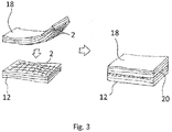
- Fig. 3 shows a step of bringing the first object 12 and the second object 18 into contact.
- the first object 12 comprises a layer of carbon nanotubes 2 on a surface 10 thereof.
- the layer of carbon nanotubes 2 has been applied, for example, by using the method step described with reference to Fig. 2 .
- the second object 18 has a surface, on which a layer of carbon nanotubes 2 has been applied.
- the layer of carbon nanotubes 2 on the second object 18 is optional.
- both the first object 12 and the second object 18 are made of thermoplastic CFRP.
- the first object 12 and the second object 18 are brought into contact, such that the layer of carbon nanotubes 2 on the surface 10 of the first object 12 is in contact with the surface of the second object 18, which shall be welded to the surface 10 of the first object 12.
- a contact surface 20 is formed between the first object 12 and the second object 18. At this contact surface 20, the layer of carbon nanotubes 2 of the first object 12 is present.
- Fig. 4 shows a schematic representation of a step of applying a voltage to the layer of carbon nanotubes 2, such that an electrical current flows through the layer of carbon nanotubes 2.
- an apparatus 21 for welding together the first object 12 and the second object 18 is used.
- Fig. 4 shows the first object 12 and the second object 18 stacked together, as it is the result of the step shown in Fig. 3 .
- the layer of carbon nanotubes 2 in the contact layer 20 is electrically contacted on two opposite sides of the contact layer 20 by respective contact units 22 of the apparatus 21.
- the layer of carbon nanotubes 2 has been applied between the first object 12 and the second object 18, such it can be contacted by the contact unit 22.
- the layer of carbon nanotubes 2 may overlap over the edge of the contact surface 20 and the first object 12 and/or the second object 18. In that case, the layer of carbon nanotubes 2 can be contacted from outside. In case one of the surfaces of the first object 12 or the second object 18 is larger than the surface of the other object, the layer of carbon nanotubes 2 can extend over this larger surface in order to be connectable by the connecting unit 22 when the two objects 12 and 18 have been brought into contact. Further, the connecting unit 22 may be deposited between the first object 12 and the second object 18 before the step of bringing the two objects together, such that the connecting unit 22 contacts the layer of carbon nanotubes 2 inside the combined objects 12 and 18.
- a voltage is applied to the layer of carbon nanotubes 2 by a control unit 24 of the apparatus 21.
- the control unit 24 comprises a voltage source 8.
- the voltage may be controlled by the control unit 24 such that a constant, predefined current I flows through the layer of carbon nanotubes 2.
- a temperature measuring device 26 for measuring a temperature T of the material of the first object 12 and/or of the material of the second object 18 may be provided.
- this temperature measuring device 26 of the apparatus 21 is a thermal camera 26 configured to output an electrical signal representative of a two-dimensional thermal image.
- the thermal image may indicate a temperature distribution within the contact surface 20. Thus, it is possible to monitor the temperature within the two combined objects 12 and 18.
- a temperature rise is caused by the current flowing through the layer of carbon nanotubes 2.
- the current flowing through the layer of carbon nanotubes 2 causes the material surrounding the carbon nanotubes 2 to be heated.
- This heating is observed by the thermal camera 26 in the form of temperature values.
- the electrical signal output by the thermal camera 26 is input into the control device 24 of the apparatus 21 via a respective input interface (not shown).
- a feedback loop may be used in the control unit 24.
- the control unit 24 may carried out control such that it is ensured that the temperature T at the contact surface 20 is within a predetermined temperature range.
- the predetermined temperature range may be set such that the temperature is high enough to melt the material of the first object 12 and the second object 18 at the contact surface 20, but not too high in order to not burn the surrounding material.
- a processor for example, a CPU
- a respective programming by software and/or by hardware may be used with a respective programming by software and/or by hardware.
- the layer of carbon nanotubes 2 may be contacted by using one large contact unit 22 over an entire length of the layer of carbon nanotubes 2.
- the layer of carbon nanotubes 2 may be contacted by using a contact unit 22 that is configured to apply different voltage values U to different positions of the layer of carbon nanotubes 2.
- certain regions of the layer of carbon nanotubes 2 may be individually supplied with a predefined current value I in order to individually control a temperature T in this region.
- the contact surface 20 is heated up by the effect of remote Joule heating, which causes material adjacent to the layer of carbon nanotubes 2 to melt.
- Material of the first object 12 and of the second object 18 melts and conjoins with each other, which welds the first object 12 and the second object 18 together.
- the material is hardened again and the first object 12 and the second object 18 are welded together.
- the above-described technique provides a method and an apparatus for welding together a first object and a second object without requiring an external heating source or an external vibration source, and without connecting any magnetic circuits or complex electric circuits.
- the presented technique is cheap, easy to use and convenient, compared to welding techniques of the prior art.
- first object and/or the second object are not limited to the shape shown in the figures.
- first object and the second object are not limited to the shape shown in the figures.
- a plurality of layers of carbon nanotubes may be formed between the first object and the second object. This conjoined layer of carbon nanotubes may be contacted in any desired way suitable for letting a current flow through the layer of carbon nanotubes.
Landscapes
- Engineering & Computer Science (AREA)
- Mechanical Engineering (AREA)
- Physics & Mathematics (AREA)
- Thermal Sciences (AREA)
- Textile Engineering (AREA)
- Lining Or Joining Of Plastics Or The Like (AREA)
- Carbon And Carbon Compounds (AREA)
Abstract
Description
- The present invention relates to a method and an apparatus for welding together a first object and a second object.
- In aircraft construction efforts are being made increasingly to use, as load-bearing components, components that are made entirely or partially of fiber-reinforced composite materials, for example carbon fiber-reinforced plastics (CFRP). One type of carbon fiber-reinforced plastic is carbon fiber-reinforced thermoplastic (thermoplastic CFRP), which comprises thermoplastic resin having thermoplastic properties. Compared to other types of carbon fiber-reinforced plastic materials (e.g., thermoset CFRP), thermoplastic CFRP has a plurality of advantages, in particular with regard to its curing process.
- In particular due to these advantages, thermoplastic CFRP is recently increasingly used, e.g., in aircraft construction. However, some aspects regarding the processing of thermoplastic CFRP are still challenging. For example, until now the most common way of joining two thermoplastic CFRP objects is by so-called "co-consolidation" in an autoclave, i.e., a large pressurized heat oven, that consumes much energy and requires a long process time. Improvement has been achieved in recent years by better thermoplastic resins requiring a scaled down version of the autoclave, i.e. TP-ovens. Separate welding processes for thermoplastic parts have also been developed, but have not yet reached an optimum. They typically all require external heating sources, such as: torches, infrared radiation, on ultrasonic devices applying mechanical vibrations. Further, known welding processes for thermoplastic objects sometimes require separate induction circuits or electrical circuits that need to be attached to the objects to be welded in order to cause heating.
- The invention is directed to the object of providing a method and an apparatus for welding together a first object and a second object, which reduces the aforementioned problems and which is simplified compared to known welding methods and apparatuses, respectively.
- The above-mentioned object is achieved by a method for welding together a first object and a second object according to claim 1. The above-mentioned object is further achieved by an apparatus for welding together a first object and a second object according to
claim 10. Advantageous embodiments are defined in the dependent claims. - According to a first aspect of the disclosure, a method for welding together a first object and a second object comprises applying a layer of carbon nanotubes onto a surface of the first object and bringing the first object and the second object into contact, such that the layer of carbon nanotubes on the surface of the first object is in contact with a surface of the second object. The method further comprises applying a voltage to the layer of carbon nanotubes, such that an electrical current flows through the layer of carbon nanotubes, wherein material of the first object adjacent to the layer of carbon nanotubes and material of the second object adjacent to the layer of carbon nanotubes is heated and melted by the electrical current and thereby welded together.
- The first object and the second object may be objects of any desired material or shape. The shape and/or material of the first object does not have to be identical to the shape and/or material of the second object. In particular, the first object and the second object may each be formed of one or a plurality of layers of carbon fiber-reinforced thermoplastic, i.e., thermoplastic carbon fiber-reinforced plastic (thermoplastic CFRP). Applying a layer of carbon nanotubes (CNTs) is not limited to a single layer of carbon nanotubes. A plurality of sub-layers of carbon nanotubes may be applied, which, in their entirety, are considered as the layer of carbon nanotubes. Thus, a plurality of carbon nanotubes may be stacked above each other in the layer of carbon nanotubes. The layer of carbon nanotubes may comprise long carbon nanotubes, which are applied in a grid-like structure. The layer of carbon nanotubes may be applied such that the individual carbon nanotubes overlap each other and thereby form a continuous layer of electrically interconnected carbon nanotubes. The surface of the first object and the surface of the second object may each be flat surfaces. Further, the surface of the first object may have a curvature, whereas the surface of the second object has a curvature corresponding to the curvature of the surface of the first object.
- In the step of bringing the first object and the second object into contact, the surface of the first object and the surface of the second object may be pressed together by a predefined pressure. This pressure may be maintained during the step of applying a voltage to the layer of carbon nanotubes.
- In the step of applying a voltage to the layer of carbon nanotubes, a control can be carried out, such that a predefined voltage is applied. Further, control can be carried out, such that a predefined current flows through the layer of carbon nanotubes. The voltage may be applied for a predefined amount of time. During the step of applying a voltage to the layer of carbon nanotubes, the first object and the second object may be pressed together. The material of the first object and/or the material of the second object may be thermoplastic material. In particular, the material of the first object and/or the material of the second object may be thermoplastic material used as thermoplastic resin material in the respective object made of thermoplastic CFRP. After the step of applying a voltage to the layer of carbon nanotubes, a cooling step may follow in order to harden the melted material.
- The method may further comprise, before the step of bringing the first object and the second object into contact, applying a further layer of carbon nanotubes onto the surface of the second object, wherein in the step of applying the voltage, the electrical current also flows through the further layer of carbon nanotubes. By applying the further layer of carbon nanotubes onto the surface of the second object, both surfaces that are brought into contact are provided with an associated layer of carbon nanotubes. In the step of bringing the first object and the second object into contact, the two layers of carbon nanotubes may conjoin to one layer of carbon nanotubes between the two objects. The carbon nanotubes in the layer of carbon nanotubes as well as the carbon nanotubes in the further layer of carbo nanotubes may be homogeneously distributed over the entire surface of the first object and/or the second object, respectively. After the first object and the second object have been brought into contact, the carbon nanotubes in the layer of carbon nanotubes or in the conjoined layer of carbon nanotubes may be arranged such that an electric current may flow through the layer of carbon nanotubes or through the conjoined layer of carbon nanotubes from one end of the respective layer to another, opposite end of the respective layer.
- The material of the first object and the material of the second object may be heated by remote Joule heating. The material of the first object and the material of the second object adjacent to the layer of carbon nanotubes may be heated such, that a current flow is generated in the carbon nanotubes of the layer of carbon nanotubes, wherein this current couples to vibrational modes of surrounding material. Atoms of the surrounding material may be caused to oscillate, which causes a heating of the material. In case the heating reaches a particular temperature (a melting temperature of the respective material), the material will start melting.
- At least one of the first object and the second object may comprise carbon fiber-reinforced plastic. The carbon fiber-reinforced plastic (CFRP) may be provided in one layer or in a plurality of layers stacked upon each other. The carbon fiber-reinforced plastic may comprise a plurality of carbon fibers embedded in a matrix of plastic resin. The first object and/or the second object may each either be entirely formed of carbon fiber-reinforced plastic or comprise parts which are made of carbon fiber-reinforced plastic.
- At least the one of the first object and the second object may comprise carbon fiber-reinforced thermoplastic. In other words, the one of the first object and the second object may comprise CFRP having thermoplastic properties. The used CFRP may comprise a resin having thermoplastic properties.
- The layer of carbon nanotubes may be applied by using a solvent comprising a plurality of carbon nanotubes. The layer of carbon nanotubes may be applied by pouring the solvent under controlled conditions. The solvent may be a solvent comprising a plurality of long carbon nanotubes. The layer of carbon nanotubes may also be applied by spraying the solvent onto the surface of the first object. Further, other types of application of the solvent are possible, wherein the solvent is applied in a controlled manner, such that a uniform layer of solvent is achieved on the surface on the first object and, alternatively, on the surface of the second object.
- The carbon nanotubes in the layer of carbon nanotubes may be arranged in a grid-like structure. In the grid-like structure, the individual carbon nanotubes may be arranged such that the carbon nanotubes overlap each other and thereby form an electrical connection between them. Although not every single carbon nanotube needs to overlap another carbon nanotube, the carbon nanotubes in the grid may be arranged such that an electrical connection between one end of the layer of carbon nanotubes to an opposite end of the layer of carbon nanotubes is established. The layer of carbon nanotubes may be arranged such that the grid-like structure homogeneously covers the surface of the first object. The layer of carbon nanotubes may be arranged such that it extends up to at least two edges of the first object.
- The method may further comprise, during the step of applying the voltage, measuring a temperature of the material of the first object and/or of the material of the second object. The method may further comprise controlling the applied voltage based on the measured temperature. The temperature may be measured at one particular point at the first object or the second object. For example, the temperature may be measured at an interface between the first object and the second object, i.e., where the first object contacts the second object. For example, the temperature may be measured in the layer of carbon nanotubes. Further, not only one but a plurality of temperatures may be measured. For example, a two-dimensional thermal image may be generated for an entire contact surface of the first object and the second object. The applied voltage may be controlled such that the measured temperature remains substantially constant. For example, a feedback loop may be used. In case a plurality of temperatures is measured, the applied voltage may be controlled such that each measured temperature is higher than a particular threshold temperature. The measured temperature may be fed into a control unit in the form of an electrical signal. The electrical signal may be used by the control unit in order to control the applied voltage based on the measured temperature.
- A thermal camera may be used for measuring the temperature. The thermal camera may be used, e.g., for generating a two-dimensional thermal image. The two-dimensional thermal image may show a temperature distribution of the entire contact surface between the first object and the second object.
- According to a second aspect of the present disclosure, an apparatus for welding together a first object and a second object comprises at least two contact units configured to apply a voltage to a layer of carbon nanotubes, which is arranged at a contact surface between a first object and a second object. The apparatus further comprises a temperature measuring device configured to measure a temperature of material of the first object adjacent to the layer of carbon nanotubes and/or of material of the second object adjacent to the layer of carbon nanotubes and a control unit configured to apply a voltage to the layer of carbon nanotubes via the contact units, and to control the applied voltage based on the measured temperature.
- The contact units may be electrically connected to the control unit. The temperature measuring device may be configured to output an electrical signal indicative of the measured temperature. The control device may comprise an input interface for receiving the electrical signal of the temperature measuring device. The control unit may be configured to control the applied voltage, such that a predefined current is flowing through the layer of carbon nanotubes. The control unit may be configured to control the voltage, such that the measured temperature is maintained substantially constant at a predefined temperature value.
- The temperature measuring device may be a thermal camera. The thermal camera may be configured to generate a thermal image and to output the thermal image in the form of an electrical signal. The control unit may comprise an input interface for receiving an electrical signal indicative of a thermal image generated by the thermal camera.
- Preferred embodiments of the invention are now described in greater detail with reference to the appended schematic drawings, wherein
- Fig. 1
- shows the principle of remote Joule heating, whereas, exemplarily, one single carbon nanotube is embedded in surrounding material and a current is flowing through the carbon nanotube;
- Fig. 2
- shows a step of applying a layer of carbon nanotubes onto a surface of a first object;
- Fig. 3
- shows a step of bringing the first object and a second object into contact; and
- Fig. 4
- shows an apparatus for welding together the first object and the second object, during a step of applying a voltage to the layer of carbon nanotubes, such that an electrical current flows through the layer of carbon nanotubes and such that the first object and the second object are welded together.
- Although the following disclosure describes welding of two objects together, wherein each of these objects comprises at least one layer of thermoplastic CFRP, it should be appreciated by those skilled in the art that the invention is not limited to this material. Any kind of suitable materials may be welded together by the method described herein, as long as these materials are suitable for being welded by heat. Further, only one of the two objects that are welded together may comprise thermoplastic CFRP, whereas the other object may be made of another suitable material. Further, although the present disclosure describes a welding process with reference to the physical phenomenon called "remote Joule heating", other physical principles, such as direct (or classical) Joule heating, may be used for generating heat at a contact surface between the two objects.
-
Fig. 1 schematically shows the principle of remote Joule heating by acarbon nanotube 2. The phenomenon of remote Joule heating was discovered by Kamal H. Baloch et al. at the University of Maryland in 2012. It has been discovered that if acarbon nanotube 2 is placed under electric current I and is inserted in a surroundingmaterial 4, the electric current I in thecarbon nanotube 2 can couple to the vibrational modes of the surroundingmaterial 4, heating it remotely. More precisely,atoms 6 of the surroundingmaterial 4 start to vibrate or oscillate, as indicated by arrows inFig. 1 . Therefore, by applying a voltage, which leads to an electrical current I through thecarbon nanotube 2,material 4 surrounding thecarbon nanotube 2 can be "remotely" heated. The phenomenon of remote Joule heating significantly differs from the typically expected principle of (direct) Joule heating, where it is assumed that electrons collide with the atoms of a conductor, generating heat locally and only in regions of non-zero current density. Although the present disclosure focuses on the phenomenon of remote Joule heating, the surroundingmaterial 4 may also be heated by the current I in thecarbon nanotube 2 in case thecarbon nanotube 2 should exhibit direct (or classical) Joule heating. In this case, the heat is transferred from thecarbon nanotube 2 to the surroundingmaterial 4. - A
voltage source 8 is used to apply a particular voltage U, which leads to a predetermined current I in thecarbon nanotube 2. For this, the current I in thecarbon nanotube 2 may be monitored by a current measurement device (not shown) and the voltage U of thevoltage source 8 may be controlled accordingly. -
Fig. 2 shows a step of applying a layer ofcarbon nanotubes 2 onto asurface 10 of afirst object 12. In the described embodiment, thefirst object 12 consists of thermoplastic CFRP. For the sake of simplicity, thefirst object 12 is shown as a platelike object having one largetop surface 10. In the shown example, thesurface 10 of thefirst object 12 shall be welded to a corresponding surface of a second object. - In the first step shown in
Fig. 2 , a layer ofcarbon nanotubes 2 is applied on thesurface 10 of thefirst object 12. As shown inFig. 2 , a carbon nanotube grid is applied on thesurface 10 of thefirst object 12, by pouring a solvent 14 containinglong carbon nanotubes 2 onto thesurface 10 under controlled conditions. For this step, a dispensingdevice 16 may be used, which is configured to apply a homogeneous layer ofcarbon nanotubes 2 onto thesurface 10 of thefirst object 12. - As shown in
Fig. 2 , theentire surface 10 of thefirst object 12, which shall later represent a contact surface with regard to the second object, is covered withcarbon nanotubes 2 in a grid-like structure. It is to be noted, that the grid-like structure shown inFig. 2 is only a schematic representation and that the layer ofcarbon nanotubes 2 may be much denser and the carbon nanotubes may be much smaller than shown inFig. 2 . Further, theindividual carbon nanotubes 2 do not need to have a particular orientation. It is rather desirable that the layer ofcarbon nanotubes 2 covers theentire surface 10 to be welded. Further, theindividual carbon nanotubes 2 overlap each other, as shown in the magnified representation inFig. 2 . By these overlappingcarbon nanotubes 2, an electrical connection is established from one end of thesurface 10 to another end of the surface 10 (in the representation ofFig. 2 , for example, from left to right). - Further, the same process step as shown in
Fig. 2 may be used for depositing a layer ofcarbon nanotubes 2 onto a surface of the second object that shall be welded together with thefirst object 12. However, this step is optional and also a second object may be used, which has no layer ofcarbon nanotubes 2 deposited on it. -
Fig. 3 shows a step of bringing thefirst object 12 and thesecond object 18 into contact. As shown in the left part ofFig. 3 , thefirst object 12 comprises a layer ofcarbon nanotubes 2 on asurface 10 thereof. The layer ofcarbon nanotubes 2 has been applied, for example, by using the method step described with reference toFig. 2 . - Further, also the
second object 18 has a surface, on which a layer ofcarbon nanotubes 2 has been applied. However, the layer ofcarbon nanotubes 2 on thesecond object 18 is optional. In the described example, both thefirst object 12 and thesecond object 18 are made of thermoplastic CFRP. As shown inFig. 3 , thefirst object 12 and thesecond object 18 are brought into contact, such that the layer ofcarbon nanotubes 2 on thesurface 10 of thefirst object 12 is in contact with the surface of thesecond object 18, which shall be welded to thesurface 10 of thefirst object 12. After bringing thefirst object 12 and thesecond object 18 into contact, acontact surface 20 is formed between thefirst object 12 and thesecond object 18. At thiscontact surface 20, the layer ofcarbon nanotubes 2 of thefirst object 12 is present. In case also a layer ofcarbon nanotubes 2 has been applied onto thesecond object 18, the two layers ofcarbon nanotubes 2 conjoin with each other and form a conjoined layer ofcarbon nanotubes 2 at thecontact surface 20. Pressure may be applied during bringing the twoobjects -
Fig. 4 shows a schematic representation of a step of applying a voltage to the layer ofcarbon nanotubes 2, such that an electrical current flows through the layer ofcarbon nanotubes 2. For carrying out this step of applying the voltage, anapparatus 21 for welding together thefirst object 12 and thesecond object 18 is used.Fig. 4 shows thefirst object 12 and thesecond object 18 stacked together, as it is the result of the step shown inFig. 3 . The layer ofcarbon nanotubes 2 in thecontact layer 20 is electrically contacted on two opposite sides of thecontact layer 20 byrespective contact units 22 of theapparatus 21. The layer ofcarbon nanotubes 2 has been applied between thefirst object 12 and thesecond object 18, such it can be contacted by thecontact unit 22. For example, the layer ofcarbon nanotubes 2 may overlap over the edge of thecontact surface 20 and thefirst object 12 and/or thesecond object 18. In that case, the layer ofcarbon nanotubes 2 can be contacted from outside. In case one of the surfaces of thefirst object 12 or thesecond object 18 is larger than the surface of the other object, the layer ofcarbon nanotubes 2 can extend over this larger surface in order to be connectable by the connectingunit 22 when the twoobjects unit 22 may be deposited between thefirst object 12 and thesecond object 18 before the step of bringing the two objects together, such that the connectingunit 22 contacts the layer ofcarbon nanotubes 2 inside the combinedobjects - A voltage is applied to the layer of
carbon nanotubes 2 by acontrol unit 24 of theapparatus 21. Thecontrol unit 24 comprises avoltage source 8. The voltage may be controlled by thecontrol unit 24 such that a constant, predefined current I flows through the layer ofcarbon nanotubes 2. Atemperature measuring device 26 for measuring a temperature T of the material of thefirst object 12 and/or of the material of thesecond object 18 may be provided. In the example shown inFig. 4 , thistemperature measuring device 26 of theapparatus 21 is athermal camera 26 configured to output an electrical signal representative of a two-dimensional thermal image. The thermal image may indicate a temperature distribution within thecontact surface 20. Thus, it is possible to monitor the temperature within the two combinedobjects carbon nanotubes 2. - According to the principle of remote Joule heating (see above) the current flowing through the layer of
carbon nanotubes 2 causes the material surrounding thecarbon nanotubes 2 to be heated. This heating is observed by thethermal camera 26 in the form of temperature values. The electrical signal output by thethermal camera 26 is input into thecontrol device 24 of theapparatus 21 via a respective input interface (not shown). This makes it possible for thecontrol unit 24 to control the applied voltage U and/or the flowing current I based on a measured temperature T. For example, a feedback loop may be used in thecontrol unit 24. For example, thecontrol unit 24 may carried out control such that it is ensured that the temperature T at thecontact surface 20 is within a predetermined temperature range. The predetermined temperature range may be set such that the temperature is high enough to melt the material of thefirst object 12 and thesecond object 18 at thecontact surface 20, but not too high in order to not burn the surrounding material. - For carrying out the control of the
control unit 24, a processor (for example, a CPU) may be used with a respective programming by software and/or by hardware. - As shown in
Fig. 4 , the layer ofcarbon nanotubes 2 may be contacted by using onelarge contact unit 22 over an entire length of the layer ofcarbon nanotubes 2. Alternatively, the layer ofcarbon nanotubes 2 may be contacted by using acontact unit 22 that is configured to apply different voltage values U to different positions of the layer ofcarbon nanotubes 2. Thus, certain regions of the layer ofcarbon nanotubes 2 may be individually supplied with a predefined current value I in order to individually control a temperature T in this region. - As described above, the
contact surface 20 is heated up by the effect of remote Joule heating, which causes material adjacent to the layer ofcarbon nanotubes 2 to melt. Material of thefirst object 12 and of thesecond object 18 melts and conjoins with each other, which welds thefirst object 12 and thesecond object 18 together. After a step of cooling, the material is hardened again and thefirst object 12 and thesecond object 18 are welded together. - The above-described technique provides a method and an apparatus for welding together a first object and a second object without requiring an external heating source or an external vibration source, and without connecting any magnetic circuits or complex electric circuits. Thus, the presented technique is cheap, easy to use and convenient, compared to welding techniques of the prior art.
- Although the above description is given with reference to the appended
figures 1 to 4 , it should be appreciated that the present disclosure is not limited to these specific embodiments. For example, a different material may be used for the first object and/or the second object. Further, the first object and the second object (and, in particular, their surfaces) are not limited to the shape shown in the figures. Further, a plurality of layers of carbon nanotubes may be formed between the first object and the second object. This conjoined layer of carbon nanotubes may be contacted in any desired way suitable for letting a current flow through the layer of carbon nanotubes.
Claims (11)
- A method for welding together a first object (12) and a second object (18), comprising:applying a layer of carbon nanotubes (2) onto a surface (10) of the first object (12);bringing the first object (12) and the second object (18) into contact, such that the layer of carbon nanotubes (2) on the surface (10) of the first object (12) is in contact with a surface of the second object (18);applying a voltage to the layer of carbon nanotubes (2), such that an electrical current flows through the layer of carbon nanotubes (2), wherein material of the first object (12) adjacent to the layer of carbon nanotubes (2) and material of the second object (18) adjacent to the layer of carbon nanotubes (2) is heated and melted by the electrical current and thereby welded together.
- The method according to claim 1, further comprising:before the step of bringing the first object (12) and the second object (18) into contact, applying a further layer of carbon nanotubes (2) onto the surface of the second object (18), whereinin the step of applying the voltage, the electrical current also flows through the further layer of carbon nanotubes (2).
- The method according to claim 1 or 2, wherein the material of the first object (12) and the material of the second object (18) is heated by remote Joule heating.
- The method according to any one of claims 1 to 3, wherein at least one of the first object (12) and the second object (18) comprises carbon fiber-reinforced plastic.
- The method according to claim 4, wherein at least the one of the first object (12) and the second object (18) comprises carbon fiber-reinforced thermoplastic.
- The method according to any one of claims 1 to 5, wherein the layer of carbon nanotubes (2) is applied by using a solvent (14) comprising a plurality of carbon nanotubes (2).
- The method according to any one of claims 1 to 6, wherein the carbon nanotubes (2) in the layer of carbon nanotubes (2) are arranged in a grid-like structure.
- The method according to any one of claims 1 to 7, further comprising:during the step of applying the voltage, measuring a temperature of the material of the first object (12) and/or of the material of the second object (18); andcontrolling the applied voltage based on the measured temperature.
- The method according to claim 8, wherein a thermal camera (26) is used for measuring the temperature.
- An apparatus (21) for welding together a first object (12) and a second object (18), comprising:at least two contact units (22) configured to apply a voltage to a layer of carbon nanotubes (2), which is arranged at a contact surface (20) between a first object (12) and a second object (18);a temperature measuring device (26) configured to measure a temperature of material of the first object (12) adjacent to the layer of carbon nanotubes (2) and/or of material of the second object (18) adjacent to the layer of carbon nanotubes (2); anda control unit (24) configured to apply a voltage to the layer of carbon nanotubes (2) via the contact units (22), and to control the applied voltage based on the measured temperature.
- The apparatus (21) of claim 10, wherein the temperature measuring device (26) is a thermal camera (26).
Priority Applications (3)
| Application Number | Priority Date | Filing Date | Title |
|---|---|---|---|
| EP15199470.4A EP3178635B1 (en) | 2015-12-11 | 2015-12-11 | Method for welding together a first object and a second object |
| CA2946022A CA2946022A1 (en) | 2015-12-11 | 2016-10-14 | Method and apparatus for welding together a first object and a second object |
| US15/375,517 US20170165903A1 (en) | 2015-12-11 | 2016-12-12 | Method and apparatus for welding together a first object and a second object |
Applications Claiming Priority (1)
| Application Number | Priority Date | Filing Date | Title |
|---|---|---|---|
| EP15199470.4A EP3178635B1 (en) | 2015-12-11 | 2015-12-11 | Method for welding together a first object and a second object |
Publications (2)
| Publication Number | Publication Date |
|---|---|
| EP3178635A1 true EP3178635A1 (en) | 2017-06-14 |
| EP3178635B1 EP3178635B1 (en) | 2019-10-30 |
Family
ID=54979387
Family Applications (1)
| Application Number | Title | Priority Date | Filing Date |
|---|---|---|---|
| EP15199470.4A Active EP3178635B1 (en) | 2015-12-11 | 2015-12-11 | Method for welding together a first object and a second object |
Country Status (3)
| Country | Link |
|---|---|
| US (1) | US20170165903A1 (en) |
| EP (1) | EP3178635B1 (en) |
| CA (1) | CA2946022A1 (en) |
Cited By (1)
| Publication number | Priority date | Publication date | Assignee | Title |
|---|---|---|---|---|
| DE102017130927A1 (en) * | 2017-12-21 | 2019-06-27 | Airbus Operations Gmbh | Method for producing a vehicle component from a fiber-reinforced plastic |
Families Citing this family (4)
| Publication number | Priority date | Publication date | Assignee | Title |
|---|---|---|---|---|
| DE102017119491A1 (en) * | 2017-08-25 | 2019-02-28 | Airbus Operations Gmbh | Method and apparatus for welding a thermoset object to another object via thermoplastic outer layers |
| CN110293298B (en) * | 2019-06-06 | 2021-06-04 | 沈阳航空航天大学 | CNT (carbon nanotube) -reinforced lightweight alloy resistance welding resin welding head and preparation method thereof |
| EP4431266A1 (en) * | 2023-03-13 | 2024-09-18 | Facc Ag | Induction welding method and device for inductive welding |
| WO2025210268A1 (en) * | 2024-04-05 | 2025-10-09 | Airbus Defence And Space Sas | Manufacture of at least one portion of an object, corresponding assembly tool, method for controlling the tool, and resulting objects |
Citations (5)
| Publication number | Priority date | Publication date | Assignee | Title |
|---|---|---|---|---|
| US20110094671A1 (en) * | 2009-10-22 | 2011-04-28 | Tsinghua University | Method for bonding members |
| US20120103509A1 (en) * | 2010-10-29 | 2012-05-03 | Hon Hai Precision Industry Co., Ltd. | Method for bonding members |
| US20130062902A1 (en) * | 2010-03-30 | 2013-03-14 | Lisa Draexlmaier Gmbh | Method for producing inner cladding parts by lamination, and inner cladding part |
| US20130087278A1 (en) * | 2011-10-07 | 2013-04-11 | National Tsing Hua University | Method for bonding components by utilizing joule heating to cure carbon nanotube-epoxy resin composite adhesive |
| CN103333621B (en) * | 2013-07-10 | 2015-02-04 | 昆明纳太能源科技有限公司 | Bucky paper electrocaloric effect-based fusion method and composite material thereof |
Family Cites Families (5)
| Publication number | Priority date | Publication date | Assignee | Title |
|---|---|---|---|---|
| JP2005536583A (en) * | 2002-06-28 | 2005-12-02 | テルミオン システムズ インターナショナル | How to accelerate joint hardening |
| TWI392582B (en) * | 2009-12-18 | 2013-04-11 | 鴻海精密工業股份有限公司 | Method for bonding two substrates |
| US20160059534A1 (en) * | 2012-06-27 | 2016-03-03 | Metna Co | Joining via Slender Nanomaterials: Materials, Procedures and Applications Thereof |
| US20140008907A1 (en) * | 2012-07-05 | 2014-01-09 | Thercom Holdings, Llc | Method and coupler for joining polymeric tubular objects |
| GB2525614A (en) * | 2014-04-29 | 2015-11-04 | Tods Aerospace Ltd | Resistance welding of thermoplastic composite components |
-
2015
- 2015-12-11 EP EP15199470.4A patent/EP3178635B1/en active Active
-
2016
- 2016-10-14 CA CA2946022A patent/CA2946022A1/en not_active Abandoned
- 2016-12-12 US US15/375,517 patent/US20170165903A1/en not_active Abandoned
Patent Citations (5)
| Publication number | Priority date | Publication date | Assignee | Title |
|---|---|---|---|---|
| US20110094671A1 (en) * | 2009-10-22 | 2011-04-28 | Tsinghua University | Method for bonding members |
| US20130062902A1 (en) * | 2010-03-30 | 2013-03-14 | Lisa Draexlmaier Gmbh | Method for producing inner cladding parts by lamination, and inner cladding part |
| US20120103509A1 (en) * | 2010-10-29 | 2012-05-03 | Hon Hai Precision Industry Co., Ltd. | Method for bonding members |
| US20130087278A1 (en) * | 2011-10-07 | 2013-04-11 | National Tsing Hua University | Method for bonding components by utilizing joule heating to cure carbon nanotube-epoxy resin composite adhesive |
| CN103333621B (en) * | 2013-07-10 | 2015-02-04 | 昆明纳太能源科技有限公司 | Bucky paper electrocaloric effect-based fusion method and composite material thereof |
Non-Patent Citations (2)
| Title |
|---|
| DUBE ET AL: "Current leakage prevention in resistance welding of carbon fibre reinforced thermoplastics", COMPOSITES SCIENCE AND TECHNOLOGY, ELSEVIER, UK, vol. 68, no. 6, 13 March 2008 (2008-03-13), pages 1579 - 1587, XP022527277, ISSN: 0266-3538, DOI: 10.1016/J.COMPSCITECH.2007.09.008 * |
| MCKNIGHT S H ET AL: "SCALING ISSUES IN RESISTANCE-WELDED THERMOPLASTIC COMPOSITE JOINTS", ADVANCES IN POLYMER TECHNOLOGY, WILEY AND SONS, HOBOKEN, NJ, US, vol. 16, no. 4, 21 December 1997 (1997-12-21), pages 279 - 295, XP000727181, ISSN: 0730-6679, DOI: 10.1002/(SICI)1098-2329(199711)16:4<279::AID-ADV3>3.0.CO;2-S * |
Cited By (1)
| Publication number | Priority date | Publication date | Assignee | Title |
|---|---|---|---|---|
| DE102017130927A1 (en) * | 2017-12-21 | 2019-06-27 | Airbus Operations Gmbh | Method for producing a vehicle component from a fiber-reinforced plastic |
Also Published As
| Publication number | Publication date |
|---|---|
| EP3178635B1 (en) | 2019-10-30 |
| CA2946022A1 (en) | 2017-06-11 |
| US20170165903A1 (en) | 2017-06-15 |
Similar Documents
| Publication | Publication Date | Title |
|---|---|---|
| US20170165903A1 (en) | Method and apparatus for welding together a first object and a second object | |
| EP3318389A1 (en) | Systems and methods for thermal control of additive manufacturing | |
| NL2000615C2 (en) | Method and device for electromagnetic welding of molded parts. | |
| JP2014513641A (en) | Thermoplastic induction welding apparatus and method | |
| US20180235030A1 (en) | Additively manufactured composite heater | |
| US20040055699A1 (en) | Method for accelerated bondline curing | |
| CN105983742A (en) | Method and system for additive manufacturing using high energy source and hot-wire | |
| CN104228059B (en) | Thermosetting polymer matrix composite resistance welding device and method | |
| KR102202248B1 (en) | Shim manufacturing system | |
| CN105983741A (en) | Method and system for additive manufacturing using high energy source and hot-wire | |
| CN1557628A (en) | Ultrasonic vibration assisted resistor implant welding method for thermoplastic resin matrix composites | |
| JP2021526471A (en) | Methods and equipment for joining molded parts by electromagnetic welding | |
| US11452178B2 (en) | Highly formable smart susceptor blankets | |
| JP6358818B2 (en) | Method for fusing fiber reinforced thermoplastic resin member | |
| CN112776379B (en) | Component and method for repairing thermoplastic composite material | |
| JP7594148B2 (en) | Method and system for curing thermoset composite materials - Patents.com | |
| CN110014660B (en) | Method for manufacturing a carrier component, carrier component and carrier having the carrier component | |
| JP2019093714A (en) | Joint method of thermoplastic element | |
| JP2012187903A (en) | Method of fusing cfrtp material | |
| JP6481085B2 (en) | Solder joining method and solder joining apparatus | |
| WO2016006265A1 (en) | Method for repairing damaged part of material including thermoplastic resin | |
| US10744721B2 (en) | Joining method and apparatus | |
| GB2628175A (en) | Composite manufacturing method and apparatus | |
| EP0924054A2 (en) | Welding element for thermoplastic parts | |
| JP7402741B2 (en) | Fusion method and joined body |
Legal Events
| Date | Code | Title | Description |
|---|---|---|---|
| PUAI | Public reference made under article 153(3) epc to a published international application that has entered the european phase |
Free format text: ORIGINAL CODE: 0009012 |
|
| STAA | Information on the status of an ep patent application or granted ep patent |
Free format text: STATUS: THE APPLICATION HAS BEEN PUBLISHED |
|
| AK | Designated contracting states |
Kind code of ref document: A1 Designated state(s): AL AT BE BG CH CY CZ DE DK EE ES FI FR GB GR HR HU IE IS IT LI LT LU LV MC MK MT NL NO PL PT RO RS SE SI SK SM TR |
|
| AX | Request for extension of the european patent |
Extension state: BA ME |
|
| STAA | Information on the status of an ep patent application or granted ep patent |
Free format text: STATUS: REQUEST FOR EXAMINATION WAS MADE |
|
| 17P | Request for examination filed |
Effective date: 20170911 |
|
| RBV | Designated contracting states (corrected) |
Designated state(s): AL AT BE BG CH CY CZ DE DK EE ES FI FR GB GR HR HU IE IS IT LI LT LU LV MC MK MT NL NO PL PT RO RS SE SI SK SM TR |
|
| STAA | Information on the status of an ep patent application or granted ep patent |
Free format text: STATUS: EXAMINATION IS IN PROGRESS |
|
| 17Q | First examination report despatched |
Effective date: 20181126 |
|
| GRAP | Despatch of communication of intention to grant a patent |
Free format text: ORIGINAL CODE: EPIDOSNIGR1 |
|
| STAA | Information on the status of an ep patent application or granted ep patent |
Free format text: STATUS: GRANT OF PATENT IS INTENDED |
|
| RIC1 | Information provided on ipc code assigned before grant |
Ipc: B29K 105/06 20060101ALN20190527BHEP Ipc: B29C 65/34 20060101AFI20190527BHEP Ipc: B29K 307/04 20060101ALN20190527BHEP |
|
| INTG | Intention to grant announced |
Effective date: 20190621 |
|
| GRAS | Grant fee paid |
Free format text: ORIGINAL CODE: EPIDOSNIGR3 |
|
| GRAA | (expected) grant |
Free format text: ORIGINAL CODE: 0009210 |
|
| STAA | Information on the status of an ep patent application or granted ep patent |
Free format text: STATUS: THE PATENT HAS BEEN GRANTED |
|
| AK | Designated contracting states |
Kind code of ref document: B1 Designated state(s): AL AT BE BG CH CY CZ DE DK EE ES FI FR GB GR HR HU IE IS IT LI LT LU LV MC MK MT NL NO PL PT RO RS SE SI SK SM TR |
|
| REG | Reference to a national code |
Ref country code: GB Ref legal event code: FG4D |
|
| REG | Reference to a national code |
Ref country code: CH Ref legal event code: EP |
|
| REG | Reference to a national code |
Ref country code: AT Ref legal event code: REF Ref document number: 1195678 Country of ref document: AT Kind code of ref document: T Effective date: 20191115 |
|
| REG | Reference to a national code |
Ref country code: DE Ref legal event code: R096 Ref document number: 602015040625 Country of ref document: DE |
|
| REG | Reference to a national code |
Ref country code: IE Ref legal event code: FG4D |
|
| REG | Reference to a national code |
Ref country code: LT Ref legal event code: MG4D |
|
| PG25 | Lapsed in a contracting state [announced via postgrant information from national office to epo] |
Ref country code: SE Free format text: LAPSE BECAUSE OF FAILURE TO SUBMIT A TRANSLATION OF THE DESCRIPTION OR TO PAY THE FEE WITHIN THE PRESCRIBED TIME-LIMIT Effective date: 20191030 Ref country code: LV Free format text: LAPSE BECAUSE OF FAILURE TO SUBMIT A TRANSLATION OF THE DESCRIPTION OR TO PAY THE FEE WITHIN THE PRESCRIBED TIME-LIMIT Effective date: 20191030 Ref country code: PL Free format text: LAPSE BECAUSE OF FAILURE TO SUBMIT A TRANSLATION OF THE DESCRIPTION OR TO PAY THE FEE WITHIN THE PRESCRIBED TIME-LIMIT Effective date: 20191030 Ref country code: GR Free format text: LAPSE BECAUSE OF FAILURE TO SUBMIT A TRANSLATION OF THE DESCRIPTION OR TO PAY THE FEE WITHIN THE PRESCRIBED TIME-LIMIT Effective date: 20200131 Ref country code: NL Free format text: LAPSE BECAUSE OF FAILURE TO SUBMIT A TRANSLATION OF THE DESCRIPTION OR TO PAY THE FEE WITHIN THE PRESCRIBED TIME-LIMIT Effective date: 20191030 Ref country code: LT Free format text: LAPSE BECAUSE OF FAILURE TO SUBMIT A TRANSLATION OF THE DESCRIPTION OR TO PAY THE FEE WITHIN THE PRESCRIBED TIME-LIMIT Effective date: 20191030 Ref country code: FI Free format text: LAPSE BECAUSE OF FAILURE TO SUBMIT A TRANSLATION OF THE DESCRIPTION OR TO PAY THE FEE WITHIN THE PRESCRIBED TIME-LIMIT Effective date: 20191030 Ref country code: NO Free format text: LAPSE BECAUSE OF FAILURE TO SUBMIT A TRANSLATION OF THE DESCRIPTION OR TO PAY THE FEE WITHIN THE PRESCRIBED TIME-LIMIT Effective date: 20200130 Ref country code: PT Free format text: LAPSE BECAUSE OF FAILURE TO SUBMIT A TRANSLATION OF THE DESCRIPTION OR TO PAY THE FEE WITHIN THE PRESCRIBED TIME-LIMIT Effective date: 20200302 Ref country code: BG Free format text: LAPSE BECAUSE OF FAILURE TO SUBMIT A TRANSLATION OF THE DESCRIPTION OR TO PAY THE FEE WITHIN THE PRESCRIBED TIME-LIMIT Effective date: 20200130 |
|
| PGFP | Annual fee paid to national office [announced via postgrant information from national office to epo] |
Ref country code: ES Payment date: 20200121 Year of fee payment: 5 |
|
| REG | Reference to a national code |
Ref country code: NL Ref legal event code: MP Effective date: 20191030 |
|
| PG25 | Lapsed in a contracting state [announced via postgrant information from national office to epo] |
Ref country code: RS Free format text: LAPSE BECAUSE OF FAILURE TO SUBMIT A TRANSLATION OF THE DESCRIPTION OR TO PAY THE FEE WITHIN THE PRESCRIBED TIME-LIMIT Effective date: 20191030 Ref country code: IS Free format text: LAPSE BECAUSE OF FAILURE TO SUBMIT A TRANSLATION OF THE DESCRIPTION OR TO PAY THE FEE WITHIN THE PRESCRIBED TIME-LIMIT Effective date: 20200229 Ref country code: HR Free format text: LAPSE BECAUSE OF FAILURE TO SUBMIT A TRANSLATION OF THE DESCRIPTION OR TO PAY THE FEE WITHIN THE PRESCRIBED TIME-LIMIT Effective date: 20191030 |
|
| PG25 | Lapsed in a contracting state [announced via postgrant information from national office to epo] |
Ref country code: AL Free format text: LAPSE BECAUSE OF FAILURE TO SUBMIT A TRANSLATION OF THE DESCRIPTION OR TO PAY THE FEE WITHIN THE PRESCRIBED TIME-LIMIT Effective date: 20191030 |
|
| PG25 | Lapsed in a contracting state [announced via postgrant information from national office to epo] |
Ref country code: ES Free format text: LAPSE BECAUSE OF FAILURE TO SUBMIT A TRANSLATION OF THE DESCRIPTION OR TO PAY THE FEE WITHIN THE PRESCRIBED TIME-LIMIT Effective date: 20191030 Ref country code: DK Free format text: LAPSE BECAUSE OF FAILURE TO SUBMIT A TRANSLATION OF THE DESCRIPTION OR TO PAY THE FEE WITHIN THE PRESCRIBED TIME-LIMIT Effective date: 20191030 Ref country code: EE Free format text: LAPSE BECAUSE OF FAILURE TO SUBMIT A TRANSLATION OF THE DESCRIPTION OR TO PAY THE FEE WITHIN THE PRESCRIBED TIME-LIMIT Effective date: 20191030 Ref country code: CZ Free format text: LAPSE BECAUSE OF FAILURE TO SUBMIT A TRANSLATION OF THE DESCRIPTION OR TO PAY THE FEE WITHIN THE PRESCRIBED TIME-LIMIT Effective date: 20191030 Ref country code: RO Free format text: LAPSE BECAUSE OF FAILURE TO SUBMIT A TRANSLATION OF THE DESCRIPTION OR TO PAY THE FEE WITHIN THE PRESCRIBED TIME-LIMIT Effective date: 20191030 |
|
| REG | Reference to a national code |
Ref country code: CH Ref legal event code: PL Ref country code: DE Ref legal event code: R097 Ref document number: 602015040625 Country of ref document: DE |
|
| REG | Reference to a national code |
Ref country code: AT Ref legal event code: MK05 Ref document number: 1195678 Country of ref document: AT Kind code of ref document: T Effective date: 20191030 |
|
| REG | Reference to a national code |
Ref country code: BE Ref legal event code: MM Effective date: 20191231 |
|
| PG25 | Lapsed in a contracting state [announced via postgrant information from national office to epo] |
Ref country code: SM Free format text: LAPSE BECAUSE OF FAILURE TO SUBMIT A TRANSLATION OF THE DESCRIPTION OR TO PAY THE FEE WITHIN THE PRESCRIBED TIME-LIMIT Effective date: 20191030 Ref country code: IT Free format text: LAPSE BECAUSE OF FAILURE TO SUBMIT A TRANSLATION OF THE DESCRIPTION OR TO PAY THE FEE WITHIN THE PRESCRIBED TIME-LIMIT Effective date: 20191030 Ref country code: SK Free format text: LAPSE BECAUSE OF FAILURE TO SUBMIT A TRANSLATION OF THE DESCRIPTION OR TO PAY THE FEE WITHIN THE PRESCRIBED TIME-LIMIT Effective date: 20191030 Ref country code: MC Free format text: LAPSE BECAUSE OF FAILURE TO SUBMIT A TRANSLATION OF THE DESCRIPTION OR TO PAY THE FEE WITHIN THE PRESCRIBED TIME-LIMIT Effective date: 20191030 |
|
| PLBE | No opposition filed within time limit |
Free format text: ORIGINAL CODE: 0009261 |
|
| STAA | Information on the status of an ep patent application or granted ep patent |
Free format text: STATUS: NO OPPOSITION FILED WITHIN TIME LIMIT |
|
| 26N | No opposition filed |
Effective date: 20200731 |
|
| PG25 | Lapsed in a contracting state [announced via postgrant information from national office to epo] |
Ref country code: LU Free format text: LAPSE BECAUSE OF NON-PAYMENT OF DUE FEES Effective date: 20191211 Ref country code: IE Free format text: LAPSE BECAUSE OF NON-PAYMENT OF DUE FEES Effective date: 20191211 |
|
| PG25 | Lapsed in a contracting state [announced via postgrant information from national office to epo] |
Ref country code: SI Free format text: LAPSE BECAUSE OF FAILURE TO SUBMIT A TRANSLATION OF THE DESCRIPTION OR TO PAY THE FEE WITHIN THE PRESCRIBED TIME-LIMIT Effective date: 20191030 Ref country code: BE Free format text: LAPSE BECAUSE OF NON-PAYMENT OF DUE FEES Effective date: 20191231 Ref country code: LI Free format text: LAPSE BECAUSE OF NON-PAYMENT OF DUE FEES Effective date: 20191231 Ref country code: CH Free format text: LAPSE BECAUSE OF NON-PAYMENT OF DUE FEES Effective date: 20191231 Ref country code: AT Free format text: LAPSE BECAUSE OF FAILURE TO SUBMIT A TRANSLATION OF THE DESCRIPTION OR TO PAY THE FEE WITHIN THE PRESCRIBED TIME-LIMIT Effective date: 20191030 |
|
| PG25 | Lapsed in a contracting state [announced via postgrant information from national office to epo] |
Ref country code: CY Free format text: LAPSE BECAUSE OF FAILURE TO SUBMIT A TRANSLATION OF THE DESCRIPTION OR TO PAY THE FEE WITHIN THE PRESCRIBED TIME-LIMIT Effective date: 20191030 |
|
| PG25 | Lapsed in a contracting state [announced via postgrant information from national office to epo] |
Ref country code: HU Free format text: LAPSE BECAUSE OF FAILURE TO SUBMIT A TRANSLATION OF THE DESCRIPTION OR TO PAY THE FEE WITHIN THE PRESCRIBED TIME-LIMIT; INVALID AB INITIO Effective date: 20151211 Ref country code: MT Free format text: LAPSE BECAUSE OF FAILURE TO SUBMIT A TRANSLATION OF THE DESCRIPTION OR TO PAY THE FEE WITHIN THE PRESCRIBED TIME-LIMIT Effective date: 20191030 |
|
| PGFP | Annual fee paid to national office [announced via postgrant information from national office to epo] |
Ref country code: DE Payment date: 20211210 Year of fee payment: 7 |
|
| PG25 | Lapsed in a contracting state [announced via postgrant information from national office to epo] |
Ref country code: TR Free format text: LAPSE BECAUSE OF FAILURE TO SUBMIT A TRANSLATION OF THE DESCRIPTION OR TO PAY THE FEE WITHIN THE PRESCRIBED TIME-LIMIT Effective date: 20191030 |
|
| PG25 | Lapsed in a contracting state [announced via postgrant information from national office to epo] |
Ref country code: MK Free format text: LAPSE BECAUSE OF FAILURE TO SUBMIT A TRANSLATION OF THE DESCRIPTION OR TO PAY THE FEE WITHIN THE PRESCRIBED TIME-LIMIT Effective date: 20191030 |
|
| REG | Reference to a national code |
Ref country code: DE Ref legal event code: R119 Ref document number: 602015040625 Country of ref document: DE |
|
| PG25 | Lapsed in a contracting state [announced via postgrant information from national office to epo] |
Ref country code: DE Free format text: LAPSE BECAUSE OF NON-PAYMENT OF DUE FEES Effective date: 20230701 |
|
| PGFP | Annual fee paid to national office [announced via postgrant information from national office to epo] |
Ref country code: GB Payment date: 20251219 Year of fee payment: 11 |
|
| PGFP | Annual fee paid to national office [announced via postgrant information from national office to epo] |
Ref country code: FR Payment date: 20251223 Year of fee payment: 11 |