EP3178537A1 - Co2 recovery device and co2 recovery method - Google Patents
Co2 recovery device and co2 recovery method Download PDFInfo
- Publication number
- EP3178537A1 EP3178537A1 EP15856351.0A EP15856351A EP3178537A1 EP 3178537 A1 EP3178537 A1 EP 3178537A1 EP 15856351 A EP15856351 A EP 15856351A EP 3178537 A1 EP3178537 A1 EP 3178537A1
- Authority
- EP
- European Patent Office
- Prior art keywords
- section
- rinse
- water
- absorption
- column
- Prior art date
- Legal status (The legal status is an assumption and is not a legal conclusion. Google has not performed a legal analysis and makes no representation as to the accuracy of the status listed.)
- Granted
Links
Images



Classifications
-
- B—PERFORMING OPERATIONS; TRANSPORTING
- B01—PHYSICAL OR CHEMICAL PROCESSES OR APPARATUS IN GENERAL
- B01D—SEPARATION
- B01D53/00—Separation of gases or vapours; Recovering vapours of volatile solvents from gases; Chemical or biological purification of waste gases, e.g. engine exhaust gases, smoke, fumes, flue gases, aerosols
- B01D53/34—Chemical or biological purification of waste gases
- B01D53/46—Removing components of defined structure
- B01D53/62—Carbon oxides
-
- B—PERFORMING OPERATIONS; TRANSPORTING
- B01—PHYSICAL OR CHEMICAL PROCESSES OR APPARATUS IN GENERAL
- B01D—SEPARATION
- B01D53/00—Separation of gases or vapours; Recovering vapours of volatile solvents from gases; Chemical or biological purification of waste gases, e.g. engine exhaust gases, smoke, fumes, flue gases, aerosols
- B01D53/14—Separation of gases or vapours; Recovering vapours of volatile solvents from gases; Chemical or biological purification of waste gases, e.g. engine exhaust gases, smoke, fumes, flue gases, aerosols by absorption
-
- B—PERFORMING OPERATIONS; TRANSPORTING
- B01—PHYSICAL OR CHEMICAL PROCESSES OR APPARATUS IN GENERAL
- B01D—SEPARATION
- B01D53/00—Separation of gases or vapours; Recovering vapours of volatile solvents from gases; Chemical or biological purification of waste gases, e.g. engine exhaust gases, smoke, fumes, flue gases, aerosols
- B01D53/14—Separation of gases or vapours; Recovering vapours of volatile solvents from gases; Chemical or biological purification of waste gases, e.g. engine exhaust gases, smoke, fumes, flue gases, aerosols by absorption
- B01D53/1418—Recovery of products
-
- B—PERFORMING OPERATIONS; TRANSPORTING
- B01—PHYSICAL OR CHEMICAL PROCESSES OR APPARATUS IN GENERAL
- B01D—SEPARATION
- B01D53/00—Separation of gases or vapours; Recovering vapours of volatile solvents from gases; Chemical or biological purification of waste gases, e.g. engine exhaust gases, smoke, fumes, flue gases, aerosols
- B01D53/14—Separation of gases or vapours; Recovering vapours of volatile solvents from gases; Chemical or biological purification of waste gases, e.g. engine exhaust gases, smoke, fumes, flue gases, aerosols by absorption
- B01D53/1456—Removing acid components
- B01D53/1475—Removing carbon dioxide
-
- B—PERFORMING OPERATIONS; TRANSPORTING
- B01—PHYSICAL OR CHEMICAL PROCESSES OR APPARATUS IN GENERAL
- B01D—SEPARATION
- B01D53/00—Separation of gases or vapours; Recovering vapours of volatile solvents from gases; Chemical or biological purification of waste gases, e.g. engine exhaust gases, smoke, fumes, flue gases, aerosols
- B01D53/34—Chemical or biological purification of waste gases
- B01D53/73—After-treatment of removed components
-
- B—PERFORMING OPERATIONS; TRANSPORTING
- B01—PHYSICAL OR CHEMICAL PROCESSES OR APPARATUS IN GENERAL
- B01D—SEPARATION
- B01D53/00—Separation of gases or vapours; Recovering vapours of volatile solvents from gases; Chemical or biological purification of waste gases, e.g. engine exhaust gases, smoke, fumes, flue gases, aerosols
- B01D53/34—Chemical or biological purification of waste gases
- B01D53/74—General processes for purification of waste gases; Apparatus or devices specially adapted therefor
- B01D53/77—Liquid phase processes
- B01D53/78—Liquid phase processes with gas-liquid contact
-
- B—PERFORMING OPERATIONS; TRANSPORTING
- B01—PHYSICAL OR CHEMICAL PROCESSES OR APPARATUS IN GENERAL
- B01D—SEPARATION
- B01D53/00—Separation of gases or vapours; Recovering vapours of volatile solvents from gases; Chemical or biological purification of waste gases, e.g. engine exhaust gases, smoke, fumes, flue gases, aerosols
- B01D53/34—Chemical or biological purification of waste gases
- B01D53/74—General processes for purification of waste gases; Apparatus or devices specially adapted therefor
- B01D53/77—Liquid phase processes
- B01D53/79—Injecting reactants
-
- B—PERFORMING OPERATIONS; TRANSPORTING
- B01—PHYSICAL OR CHEMICAL PROCESSES OR APPARATUS IN GENERAL
- B01D—SEPARATION
- B01D53/00—Separation of gases or vapours; Recovering vapours of volatile solvents from gases; Chemical or biological purification of waste gases, e.g. engine exhaust gases, smoke, fumes, flue gases, aerosols
- B01D53/34—Chemical or biological purification of waste gases
- B01D53/96—Regeneration, reactivation or recycling of reactants
-
- F—MECHANICAL ENGINEERING; LIGHTING; HEATING; WEAPONS; BLASTING
- F01—MACHINES OR ENGINES IN GENERAL; ENGINE PLANTS IN GENERAL; STEAM ENGINES
- F01K—STEAM ENGINE PLANTS; STEAM ACCUMULATORS; ENGINE PLANTS NOT OTHERWISE PROVIDED FOR; ENGINES USING SPECIAL WORKING FLUIDS OR CYCLES
- F01K23/00—Plants characterised by more than one engine delivering power external to the plant, the engines being driven by different fluids
- F01K23/02—Plants characterised by more than one engine delivering power external to the plant, the engines being driven by different fluids the engine cycles being thermally coupled
- F01K23/06—Plants characterised by more than one engine delivering power external to the plant, the engines being driven by different fluids the engine cycles being thermally coupled combustion heat from one cycle heating the fluid in another cycle
- F01K23/10—Plants characterised by more than one engine delivering power external to the plant, the engines being driven by different fluids the engine cycles being thermally coupled combustion heat from one cycle heating the fluid in another cycle with exhaust fluid of one cycle heating the fluid in another cycle
- F01K23/103—Plants characterised by more than one engine delivering power external to the plant, the engines being driven by different fluids the engine cycles being thermally coupled combustion heat from one cycle heating the fluid in another cycle with exhaust fluid of one cycle heating the fluid in another cycle with afterburner in exhaust boiler
- F01K23/105—Regulating means specially adapted therefor
-
- F—MECHANICAL ENGINEERING; LIGHTING; HEATING; WEAPONS; BLASTING
- F02—COMBUSTION ENGINES; HOT-GAS OR COMBUSTION-PRODUCT ENGINE PLANTS
- F02C—GAS-TURBINE PLANTS; AIR INTAKES FOR JET-PROPULSION PLANTS; CONTROLLING FUEL SUPPLY IN AIR-BREATHING JET-PROPULSION PLANTS
- F02C6/00—Plural gas-turbine plants; Combinations of gas-turbine plants with other apparatus; Adaptations of gas-turbine plants for special use
- F02C6/18—Plural gas-turbine plants; Combinations of gas-turbine plants with other apparatus; Adaptations of gas-turbine plants for special use using the waste heat of gas-turbine plants outside the plants themselves, e.g. gas-turbine power heat plants
-
- B—PERFORMING OPERATIONS; TRANSPORTING
- B01—PHYSICAL OR CHEMICAL PROCESSES OR APPARATUS IN GENERAL
- B01D—SEPARATION
- B01D2257/00—Components to be removed
- B01D2257/50—Carbon oxides
- B01D2257/504—Carbon dioxide
-
- B—PERFORMING OPERATIONS; TRANSPORTING
- B01—PHYSICAL OR CHEMICAL PROCESSES OR APPARATUS IN GENERAL
- B01D—SEPARATION
- B01D2258/00—Sources of waste gases
- B01D2258/02—Other waste gases
- B01D2258/0283—Flue gases
-
- Y—GENERAL TAGGING OF NEW TECHNOLOGICAL DEVELOPMENTS; GENERAL TAGGING OF CROSS-SECTIONAL TECHNOLOGIES SPANNING OVER SEVERAL SECTIONS OF THE IPC; TECHNICAL SUBJECTS COVERED BY FORMER USPC CROSS-REFERENCE ART COLLECTIONS [XRACs] AND DIGESTS
- Y02—TECHNOLOGIES OR APPLICATIONS FOR MITIGATION OR ADAPTATION AGAINST CLIMATE CHANGE
- Y02A—TECHNOLOGIES FOR ADAPTATION TO CLIMATE CHANGE
- Y02A50/00—TECHNOLOGIES FOR ADAPTATION TO CLIMATE CHANGE in human health protection, e.g. against extreme weather
- Y02A50/20—Air quality improvement or preservation, e.g. vehicle emission control or emission reduction by using catalytic converters
-
- Y—GENERAL TAGGING OF NEW TECHNOLOGICAL DEVELOPMENTS; GENERAL TAGGING OF CROSS-SECTIONAL TECHNOLOGIES SPANNING OVER SEVERAL SECTIONS OF THE IPC; TECHNICAL SUBJECTS COVERED BY FORMER USPC CROSS-REFERENCE ART COLLECTIONS [XRACs] AND DIGESTS
- Y02—TECHNOLOGIES OR APPLICATIONS FOR MITIGATION OR ADAPTATION AGAINST CLIMATE CHANGE
- Y02C—CAPTURE, STORAGE, SEQUESTRATION OR DISPOSAL OF GREENHOUSE GASES [GHG]
- Y02C20/00—Capture or disposal of greenhouse gases
- Y02C20/40—Capture or disposal of greenhouse gases of CO2
Definitions
- the present invention relates to a CO 2 recovery device and a CO 2 recovery method that reduce the concentration of basic amine compounds released while remaining in a CO 2 -removed flue gas that comes into contact with an absorption liquid with CO 2 removed therefrom.
- PTL 1 discloses providing a plurality of rinse sections that bring rinse water into gas-liquid contact with CO 2 -removed flue gas from which CO 2 has been absorbed and removed by gas-liquid contact with an absorption liquid, thereby recovering amine compounds entrained in the CO 2 -removed flue gas, and sequentially performing recovery processing of amines entrained in the CO 2 -removed flue gas in the plurality of rinse sections.
- condensed water separated by condensing moisture contained in CO 2 in the processing of removing CO 2 from the amine-based absorption liquid that has absorbed CO 2 , and regenerating the amine-based absorption liquid is used.
- PTL 2 discloses providing a cooling section that cools CO 2 -removed flue gas from which CO 2 has been absorbed and removed by the gas-liquid contact with an absorption liquid, and a contacting section that brings condensed water condensed in the cooling section into countercurrent contact with the CO 2 -removed flue gas.
- PTL 2 discloses providing a rinse section that brings rinse water into gas-liquid contact with the CO 2 -removed flue gas from which CO 2 has been absorbed and removed by gas-liquid contact with the absorption liquid, thereby recovering amine compounds entrained in the CO 2 -removed flue gas, and condensed water that has been condensed in a cooling column that cools the flue gas before CO 2 is recovered and is used as rinse water.
- the invention solves the above-described problems, and an object thereof is to provide a CO 2 recovery device and a CO 2 recovery method that can further reduce the concentration of basic amine compounds released while remaining in a CO 2 -removed flue gas.
- a first invention of the invention for solving the above problems is a CO 2 recovery device including a CO 2 absorption column that brings a CO 2 -containing flue gas containing CO 2 into contact with a CO 2 absorption liquid and removes CO 2 , and an absorption liquid regeneration column that regenerates the CO 2 absorption liquid that has absorbed the CO 2 .
- the CO 2 absorption column includes a CO 2 absorption section that absorbs CO 2 in the CO 2 -containing flue gas with the CO 2 absorption liquid, a main rinse section that is provided on a gas flow downstream side of the CO 2 absorption section, cools flue gas after CO 2 removal with rinse water, and recovers an entrained CO 2 absorbent with the rinse water, a rinse water circulation line that supplies and circulates the rinse water containing the CO 2 absorbent recovered in a liquid storage section of the main rinse section from a top part side of the main rinse section, a pre-rinse section that is provided between the CO 2 absorption section and the main rinse section, a rinse section extraction liquid supply line that extracts a portion of the rinse water containing the CO 2 absorbent from the rinse water circulation line, is connected to a top part side of a reflux section, of the absorption liquid regeneration column, and introduces the portion of the rinse water into the reflux section, and a refluxed water supply line that extracts a portion of refluxed water from a side closer to
- a second invention is the CO 2 recovery device based on the first invention in which the pre-rinse section includes a pre-rinse water circulation line that supplies and circulates pre-rinse water from a top part side of the pre-rinse section, the refluxed water supply line is connected to the pre-rinse water circulation line, and a portion of the refluxed water is introduced as the pre-rinse water.
- the pre-rinse section includes a pre-rinse water circulation line that supplies and circulates pre-rinse water from a top part side of the pre-rinse section, the refluxed water supply line is connected to the pre-rinse water circulation line, and a portion of the refluxed water is introduced as the pre-rinse water.
- a third invention is the CO 2 recovery device based on the first or second, further including a deep rinse section that is provided on a gas flow downstream side of the main rinse section, and performs deep rinsing of the flue gas after CO 2 removal after main rinsing with rinse water supplied from the outside.
- a fourth invention is a CO 2 recovery method of circulating and reusing a lean solution, from which CO 2 has been removed in an absorption liquid regeneration column, in a CO 2 absorption column, using the CO 2 absorption column that brings a CO 2 -containing flue gas containing CO 2 into contact with a CO 2 absorption liquid and removes CO 2 ; and an absorption liquid regeneration column that separates CO 2 absorption liquid and regenerates the CO 2 absorption liquid that has absorbed the CO 2 .
- the method includes pre-rinsing the CO 2 -removed flue gas is performed using pre-rinse water extracted from a portion of reflux section obtained by a portion of rinse water used for the main rinsing being extracted, introduced into a reflux section of the absorption liquid regeneration column, and mixed with high-temperature refluxed water in the reflux section when main rinsing of CO 2 -removed flue gas is performed with rinse water on a downstream side of the CO 2 absorption column, and pre-rinsing of the CO 2 -removed flue gas after CO 2 recovery is performed on an upstream side where the main rinsing is performed.
- a fifth invention is the CO 2 recovery method based on the fourth invention in which deep rinsing is performed with deep rinsing water supplied from the outside of a rinse section on a downstream side of the main rinse section.
- the concentration of basic amine compounds of the absorption liquid released while remaining in the CO 2 -removed flue gas can be further reduced, and the recovered absorption liquid can be reused.
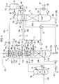
- Fig. 1 is a schematic view of the CO 2 recovery device according to Embodiment 1.
- a CO 2 recovery device 10A is a CO 2 recovery device that includes a CO 2 absorption column (hereinafter referred to as an "absorption column") 13 that brings a CO 2 -containing flue gas 11A containing CO 2 into contact with a CO 2 absorption liquid (lean solution 12B) and removes CO 2 , and an absorption liquid regeneration column (hereinafter referred to as a "regeneration column") 14 that regenerates the CO 2 absorption liquid (rich solution 12A) that has absorbed the CO 2 .
- the lean solution 12B, from which CO 2 has been removed in the regeneration column 14, is reused in the CO 2 absorption column 13.
- the absorption column 13 includes a CO 2 absorption section 13A that absorbs CO 2 in the CO 2 -containing flue gas 11A with the CO 2 absorption liquid (lean solution) 12B, a main rinse section 13C that is provided on a gas flow downstream side of the CO 2 absorption section 13A, cools the flue gas 11B after CO 2 removal with rinse water 20, and recovers an entrained CO 2 absorbent with the rinse water 20, a rinse water circulation line L 1 that supplies and circulates the rinse water 20 containing the CO 2 absorbent recovered in a liquid storage section 21 of the main rinse section 13C from a top part side of the main rinse section 13C, a pre-rinse section 13B that is provided between the CO 2 absorption section 13A and the main rinse section 13C, a rinse section extraction liquid supply line L 2 that extracts a portion 20a of the rinse water 20 containing the CO 2 absorbent from the rinse water circulation line L 1 , is connected to a top part side of a reflux section 17 of the absorption liquid regeneration column 14, and introduce
- the portion 20a of the rinse water 20 containing the CO 2 absorption liquid is extracted as it is from the rinse water circulation line L 1 .
- the invention is not limited to this.
- a storage part that temporarily stores the portion 20a of the rinse water 20 containing the CO 2 absorption liquid may be provided separately from the rinse water circulation line L 1 such that the portion 20a is extracted from this storage part.
- the CO 2 recovery device 10A of the present embodiment has the absorption column 13 that brings the CO 2 -containing flue gas 11A containing CO 2 into contact with the lean solution 12B and removes CO 2 , and the regeneration column 14 that regenerates the rich solution 12A that has absorbed CO 2 , and efficiently removes CO 2 from the CO 2 -containing flue gas 11A containing CO 2 , circulating and reusing the lean solution 12B, from which the CO 2 has been removed in the regeneration column 14, in the CO 2 absorption column 13.
- the CO 2 absorption column 13 of the present embodiment includes the CO 2 absorption section 13A that absorbs CO 2 in the CO 2 -containing flue gas 11A, the pre-rinse section 13B that is provided on the gas flow downstream side of the CO 2 absorption section 13A, and performs pre-rinsing of the flue gas 11B after CO 2 removal, and the main rinse section 13C that performs main rinsing of flue gas 11C after CO 2 removal after the pre-rinsing.
- the CO 2 -containing flue gas 11A introduced from the outside in the absorption column bottom part 13b is brought into countercurrent contact with the CO 2 absorption liquid 12 having a CO 2 absorbent, such as alkanolamine, as a base, in the CO 2 absorption section 13A provided on a lower part side of the CO 2 absorption column 13.
- CO 2 in the CO 2 -containing flue gas 11A is absorbed into the CO 2 absorption liquid 12 by a chemical reaction (R-NH 2 + H 2 O + CO 2 ⁇ R-NH 3 HCO 3 ).
- CO 2 hardly remains in the flue gas 11B after CO 2 removal that passes through the CO 2 absorption section 13A and rises inside the CO 2 absorption column 13.
- the flue gas 11B after CO 2 removal is rinsed by the main rinse section 13C on the gas flow downstream side.
- the pre-rinse section 13B before the flue gas is introduced into this main rinse section 13C, the pre-rinse section 13B is provided, and the pre-rinsing is performed in the pre-rinse section.
- the flue gas 11B after CO 2 removal is brought into gas-liquid contact with the pre-rinse water 20b and is pre-rinsed, and the CO 2 absorbent entrained in the flue gas 11B after CO 2 removal is rinsed.
- the a CO 2 absorbent is slightly included in the flue gas 11B after CO 2 removal that has passed through the CO 2 absorption section 13A.
- the CO 2 absorbent is slightly included in the rinse water 20.
- the CO 2 absorbent in the flue gas 11B after CO 2 removal is rinsed and removed in the pre-rinse water 20b.
- the flue gas 11C after CO 2 removal after having passed through the pre-rinse section 13B rises to the main rinse section 13C side via a chimney tray 16, comes into gas-liquid contact with the rinse water 20 supplied from the top part side of the main rinse section 13C, and recovers the CO 2 absorbent entrained in the flue gas 11C after CO 2 removal through circulation rinsing.
- the rinse water 20 stored in the liquid storage section 21 of the chimney tray 16 is circulated in the rinse water circulation line L 1 so as to perform circulation rinsing.
- a cooling section 22 is provided in the rinse water circulation line L 1 , and performs cooling to a predetermined temperature (for example, 40°C or lower).
- the rinse water 20 is circulated by a circulation pump 57 provided in the rinse water circulation line L 1 .
- the CO 2 absorbent entrained in the flue gas 11C after CO 2 removal can be further recovered and removed by the main rinsing using this circulating rinse water 20.
- reference sign 75 represents a mist eliminator that traps mist in gas.
- the pre-rinse section 13B and the main rinse section 13C are provided, and the CO 2 absorption liquid dissolved in the condensed water entrained in the flue gases 11B and 11C after CO 2 removal is rinsed and removed in two steps.
- the CO 2 absorption liquid entrained in the flue gases 11B and 11C after CO 2 removal can be reliably recovered and removed.
- the concentration of a CO 2 absorbent such as basic amine compounds released while remaining in the flue gas 11D after CO 2 removal released to the outside, can be further reduced.
- the rich solution 12A that has absorbed CO 2 is raised in pressure by a rich solvent pump 51 interposed in a rich solution supply pipe 50, is heated in a rich/lean solution heat exchanger 52 with the lean solution 12B regenerated in the absorption liquid regeneration column 14, and is supplied to a top part side of the absorption liquid regeneration column 14.
- the rich solution 12A released from the top part side of the regeneration column 14 to the inside of the column releases most of CO 2 in a CO 2 release part 14A through heating using the steam from a column bottom part 14b.
- the CO 2 absorption liquid 12 that released a portion or most of CO 2 within the regeneration column 14 is referred to as "semi-lean solution”.
- This semi-lean solution that is not illustrated becomes the lean solution 12B from which substantially all CO 2 has been removed when flowing down to a bottom part of the regeneration column 14.
- the lean solution 12B is heated with saturated steam 62 in a regenerative heater 61 interposed in a circulation line L 20 .
- the saturated steam 62 after heating becomes steam condensed water 63.
- CO 2 gas 41 that has entrained the water vapor dissipated from the rich solution 12A and the semi-lean solution (not illustrated) inside the column is released from a column top part 14a of the regeneration column 14. Then, the CO 2 gas 41 which has entrained the water vapor is led out by a gas release line L 21 , and the water vapor is condensed by a condenser 42 interposed in the gas release line L 21 , condensed water 44 is separated by a separation drum 43, CO 2 gas 45 is emitted to the outside of the system, and post-processing, such as compression recovery, is separately performed.
- the condensed water 44 separated in the separation drum 43 is supplied to an upper part of the absorption liquid regeneration column 14 by a condensed water circulation pump 46 interposed in a condensed water line L 22 .
- a portion of the condensed water 44 may be supplied to the rinse water circulation line L 1 of the rinse water 20 containing the CO 2 absorption liquid, and may be used for absorption of the CO 2 absorption liquid 12 entrained in the flue gas 11C after CO 2 removal.
- the regenerated CO 2 absorption liquid (lean solution 12B) is sent to the CO 2 absorption column 13 side by a lean solution pump 54 via a lean solution supply pipe 53, and is circulated and used as the CO 2 absorption liquid 12.
- the lean solution 12B is cooled up to a predetermined temperature by the cooling section 55, and is supplied into the CO 2 absorption section 13A via a nozzle 56.
- the CO 2 absorption liquid 12 forms a closed path that circulates through the CO 2 absorption column 13 and the absorption liquid regeneration column 14, and is reused in the CO 2 absorption section 13A of the CO 2 absorption column 13.
- the CO 2 absorption liquid 12 is supplied by a supply line (not illustrated) if necessary, and the CO 2 absorption liquid is regenerated by a reclaimer (not illustrated) if necessary.
- the CO 2 -containing flue gas 11A supplied to the CO 2 absorption column 13 is cooled with cooling water 71 in a cooling column 70 provided on the upstream side of the CO 2 absorption column, and is introduced into the CO 2 absorption column 13 after that.
- a portion of the cooling water 71 may also be supplied to a top part of the main rinse section 13C as the rinse water 20 of the CO 2 absorption column 13, and may be used for rinsing of the CO 2 absorption liquid 12 entrained in the flue gas 11B after CO 2 removal.
- reference sign 72 represents a circulation pump
- 73 represents a cooler
- 74 represents a circulation line.
- the portion 20a of the rinse water 20 used in the main rinse section 13C is introduced into the reflux section 17 of the regeneration column 14, and a portion of refluxed water extracted from this reflux section 17 is used as the rinse water to be used in the pre-rinse section 13B within the absorption column 13.
- the portion 20a of the rinse water 20 containing the CO 2 absorbent is extracted from the rinse water circulation line L 1 of the main rinse section 13C by the rinse section extraction liquid supply line L 2 .
- the rinse section extraction liquid supply line L 2 is connected to an introduction position X on the column top part 14a side of the reflux section 17 of the absorption liquid regeneration column 14, and the portion 20a of the rinse water 20 containing the CO 2 absorbent is introduced into the reflux section 17 at this introduction position.
- the extraction amount of the portion 20a of the rinse water 20 is adjusted by an adjusting valve 24 interposed in the rinse section extraction liquid supply line L 2 .
- the condensed water 44 is introduced, becomes refluxed water, and is mixed with this refluxed water. Then, a portion of the refluxed water is extracted from a position Y closer to the column bottom part 14b than the introduction position X of the portion 20a of the rinse water 20 containing the CO 2 absorbent by the refluxed water supply line L 3 . Then, the refluxed water is introduced as the pre-rinse water 20b of the pre-rinse section 13B by the refluxed water supply line L 3 connected to the pre-rinse section 13B side.
- Fig. 2 is a schematic view of the main sections of the absorption liquid regeneration column according to Embodiment 1.
- the refluxed water generated by the CO 2 gas 41 that has entrained the water vapor from a lower part of the regeneration column 14 in the reflux section 17, and the portion 20a of the rinse water 20 containing the CO 2 absorbent are mixed with each other when fall from the shelf stage trays 17a to 17d.
- the portion 20a of the rinse water 20 rises in temperature, is then extracted as a portion of the refluxed water from the extraction position Y closer to the column bottom part 14b side than the portion 20a of the introduction position X of the rinse water 20, and is used as the pre-rinse water 20b of the pre-rinse section 13B.
- the regeneration column reflux section may be a plate column or a packed column.
- this plate column for example, a valve tray, a bubble cap tray, a porous plate tray, and the like of a cross current contact type having a downcomer can be exemplified.
- the number of stages of the reflux section 17 are four or more stages from a viewpoint of gas-liquid contact efficiency.
- a cross current contact type four-stage tray is illustrated in Example of Fig. 2 .
- the liquid supply from an upper stage tray 17a to a lower stage tray 17b may be performed by a method of making a liquid flow down inside the column in a downcomer part or a method of supplying a liquid to a lower stage via a pipe outside the column from the downcomer part.
- the embodiment illustrated in Fig. 2 is an example of liquid supply to a lower stage inside the column.
- gas temperature falls to, for example, about 5°C, due to the contact of the CO 2 gas 41 containing water vapor at a temperature of about 100°C with the reflux liquid and a rinse section extraction supply liquid at a low temperature, in a lowest stage tray 17d of the reflux section 17.
- the water vapor in the CO 2 gas 41 containing the water vapor is condensed. Therefore, as compared to a rinse section extraction liquid supply amount (with no supply to the reflux section) as in the related art, in the present embodiment, for example, a liquid flow rate of about 1.6 times is obtained by supplying the portion 20a of the rinse water 20 to the reflux section 17, and the condensation.
- the concentration of the absorbent in the rinse section extraction liquid falls to, for example, about 0.6 times as compared to the related art, and an extraction liquid temperature (T 1 ) of a portion of the refluxed water from the reflux section 17 rises to, for example, about 36°C higher than an introduction temperature (T 0 ) of the portion 20a of the rinse water 20 containing the CO 2 absorbent introduced into the reflux section 17.
- an equilibrium point is the concentration of the absorbent in the rinse section rinse water. If the absorbent in the rinse water has low concentration as in the present embodiment, a difference from the concentration of the absorbent in the mist is large, and the desorption of the CO 2 absorbent from the mist is markedly promoted compared to the related art.
- the liquid temperature of the pre-rinse water 20b introduced into the pre-rinse section 13B is high as in the present embodiment, not only a driving force of the above absorbent concentration difference in the liquid (absorbent equilibrium pressure difference) but also a mass transfer coefficient rises. Therefore, an absorbent desorption rate expressed by the product of the mass transfer coefficient and the driving force is markedly improved compared to the related art.
- the reboiler amount of the regenerative heater 61 can be reduced.
- the CO 2 absorption liquid 12 that is used to circulate through the CO 2 absorption column 13 and the absorption liquid regeneration column 14 is prevented from being released to the outside of the absorption column 13 by bringing the flue gases 11B and 11C after CO 2 removal into counter-current contact with the rinse water 20, thereby absorbing and removing the CO 2 absorption liquid 12 entrained in the CO 2 -removed flue gases 11B and 11C with the rinse water 20, in the pre-rinse section 13B and the main rinse section 13C.
- carbon dioxide was removed by supplying 200 Nm 3 /h of combustion flue gas containing 14% of carbon dioxide to the CO 2 absorption section 13A of the absorption column 13, and brining the combustion flue gas into countercurrent contact with a basic amine solution (CO 2 absorption liquid).
- the pre-rinse section 13B was provided on a downstream (upper part) side of the CO 2 absorption section 13A.
- the pre-rinse water 20b of the pre-rinse section 13B there was used one obtained by the portion 20a of the rinse water 20 used in the main rinse section 13C being extracted, introduced into the reflux section 17 on the regeneration column 14 side, mixed with the high-temperature refluxed water in the reflux section 17, and extracted therefrom.
- the pre-rinse water 20b and the flue gas 11B after CO 2 removal were brought into countercurrent contact with each other, were made to flow down directly to the CO 2 absorption liquid of the CO 2 absorption section 13A, were brought into countercurrent contact with the rinse water in a liquid/gas ratio of 4L/Nm 3 in the main rinse section 13C, and were passed through a mist eliminator 75 at an outlet.
- Fig. 5 is a graph in which the concentrations of entrained substances in absorption column outlet gases in Test Example 1 are contrasted.
- the left side represents a related-art method that is a case where a portion of the rinse water 20 was supplied as it is from the main rinse section to the pre-rinse section.
- the right side represents a case where high-temperature diluted pre-rinse water 20b obtained by the portion 20a of the rinse water 20 used in the main rinse section 13C being extracted, introduced into the reflux section 17 on the regeneration column 14, mixed with the high-temperature refluxed water in the reflux section 17, and extracted therefrom was used for the pre-rinse section 13B according to the present embodiment.
- the concentration ratio of an entrained substance in the absorption column outlet gas (CO 2 absorption liquid-removed flue gas 11D) was reduced to 0.96 in the present test example if the concentration ratio was set to 1 in the related art.
- a CO 2 recovery device 10B of the present embodiment further includes a deep rinse section 13D, which is provided on the gas flow downstream side (column upper stage side) of the main rinse section 13C, and performs deep rinsing with the rinse water supplied from the outside of the rinse section, in the CO 2 recovery device 10A illustrated in Fig. 1 .
- a branch line L 23 which supplies a portion 44a of the condensed water 44 separated out of the CO 2 gas 41 that has entrained the water vapor released from the column top part 14a of the regeneration column 14 to the outside, is connected to the deep rinse section 13D. Then, the portion 44a of the condensed water 44 is supplied by the branch line L 23 , and is used as the rinse water in the deep rinse section 13D.
- a cooling section 25 may be provided in the branch line L 23 so as to cool the portion 44a of the condensed water 44 to a predetermined temperature (for example, 40°C or lower).
- the portion 44a of the condensed water 44 is separated out of the CO 2 gas 41 that has entrained the water vapor released from the regeneration column 14 to the outside. Hence, since the condensed water 44 is water with almost no entrainment of the CO 2 absorption liquid, the rinsing effects of the deep rinsing are exhibited.
- ion exchanged water may be separately provided as the deep rinse water in the deep rinse section 13D besides using the portion 44a of the condensed water 44.
- a liquid with a low gas-entrained substance concentration such as the CO 2 absorption liquid
- the deep rinse water is used as the deep rinse water, and is brought into gas-liquid contact with the flue gas 11D after CO 2 removal on a rearmost downstream side (column top part 13a side) on the final stage of the rinse section. Accordingly, the concentration of the CO 2 absorption liquid diffused from the column top part 13a of the absorption column 13 to the outside can be further reduced.
- FIG. 4 is a schematic view of the CO 2 recovery device according to Embodiment 3.
- the same components as those of the CO 2 recovery devices 10A and 10B according to Embodiments 1 and 2 illustrated in Figs. 1 and 3 will be designated by the same reference signs, and the duplicate description thereof will be omitted.
- a pre-rinse water circulation line L 4 through which the pre-rinse water 20b circulates is installed in the pre-rinse section 13B, in the CO 2 recovery device 10B illustrated in Fig. 3 .
- the pre-rinse water 20b stored in the liquid storage section 21 of the chimney tray 16 of the pre-rinse section 13B is introduced into the pre-rinse water circulation line L 4 . Also, the pre-rinse water 20b is circulated by a circulation pump 58 provided in the pre-rinse water circulation line L 4 . Therefore, in the pre-rinse section 13B of the present embodiment, the pre-rinse water 20b that falls in the liquid storage section 21 is recovered, and is circulated and reused in the pre-rinse water circulation line L 4 .
- an end part of the refluxed water supply line L 3 that extracts a portion of the refluxed water is connected to the pre-rinse water circulation line L 4 such that the portion is introduce as the pre-rinse water 20b of the pre-rinse section 13B.
- the present embodiment includes a pre-rinse water surplus extraction line L 5 that extracts a portion of the pre-rinse water 20b as the surplus water from the pre-rinse water circulation line L 4 .
- An end part of the pre-rinse water surplus extraction line L 5 is connected to the lean solution supply pipe 53 that supplies the lean solution 12B. Accordingly, the extraction water obtained by extracting a portion of the pre-rinse water 20b joins the lean solution 12B so as to be introduced into the CO 2 absorption section 13A.
- the surplus water extracted from the pre-rinse water surplus extraction line L 5 , and supplied to the lean solution supply pipe 53 is uniformly mixed with the lean solution 12B.
- This mixed lean solution is then cooled by the cooling section 55 provided in the lean solution supply pipe 53, so that further efficient absorption of CO 2 in the CO 2 absorption section 13A can be achieved.
Landscapes
- Engineering & Computer Science (AREA)
- Chemical & Material Sciences (AREA)
- Chemical Kinetics & Catalysis (AREA)
- Analytical Chemistry (AREA)
- General Chemical & Material Sciences (AREA)
- Oil, Petroleum & Natural Gas (AREA)
- Environmental & Geological Engineering (AREA)
- Biomedical Technology (AREA)
- Health & Medical Sciences (AREA)
- Combustion & Propulsion (AREA)
- Mechanical Engineering (AREA)
- General Engineering & Computer Science (AREA)
- Sustainable Development (AREA)
- Life Sciences & Earth Sciences (AREA)
- Treating Waste Gases (AREA)
- Gas Separation By Absorption (AREA)
Abstract
Description
- The present invention relates to a CO2 recovery device and a CO2 recovery method that reduce the concentration of basic amine compounds released while remaining in a CO2-removed flue gas that comes into contact with an absorption liquid with CO2 removed therefrom.
- As one of the causes of the global warming phenomenon, the greenhouse effect caused by CO2 is pointed out, and countermeasures thereagainst have also been required internationally in order to protect the environment of earth. As generation sources of CO2, in the fields of activity of all the human beings that combust fossil fuels, the requirement for suppression of emission of CO2 tends to become stronger. Along with this, methods of bringing flue gas of boilers into contact with amine-based absorption liquids, such as aqueous amine compound solutions and removing and recovering CO2 in the flue gas have been energetically studied for, for example, power generation facilities, such as thermoelectric power plants that use a large quantity of fossil fuels.
- In a case where CO2 is recovered from flue gas using such absorption liquids, amine compounds are entrained in CO2-removed flue gas from which CO2 has been recovered. Also, in order to prevent a situation in which air pollution caused by the amine compounds occurs, it is necessary to reduce the emission amount of the amine compounds emitted together with the CO2-removed flue gas.
- In the related art, PTL 1 discloses providing a plurality of rinse sections that bring rinse water into gas-liquid contact with CO2-removed flue gas from which CO2 has been absorbed and removed by gas-liquid contact with an absorption liquid, thereby recovering amine compounds entrained in the CO2-removed flue gas, and sequentially performing recovery processing of amines entrained in the CO2-removed flue gas in the plurality of rinse sections. As the rinse water of this PTL 1, condensed water separated by condensing moisture contained in CO2 in the processing of removing CO2 from the amine-based absorption liquid that has absorbed CO2, and regenerating the amine-based absorption liquid is used.
- Additionally, in the related art, PTL 2 discloses providing a cooling section that cools CO2-removed flue gas from which CO2 has been absorbed and removed by the gas-liquid contact with an absorption liquid, and a contacting section that brings condensed water condensed in the cooling section into countercurrent contact with the CO2-removed flue gas. Moreover, PTL 2 discloses providing a rinse section that brings rinse water into gas-liquid contact with the CO2-removed flue gas from which CO2 has been absorbed and removed by gas-liquid contact with the absorption liquid, thereby recovering amine compounds entrained in the CO2-removed flue gas, and condensed water that has been condensed in a cooling column that cools the flue gas before CO2 is recovered and is used as rinse water.
-
- [PTL 1] Japanese Unexamined Patent Application Publication No.
2002-126439 - [PTL 2] Japanese Unexamined Patent Application Publication No.
8-80421 - However, in recent years, it has been desired to further reduce the concentration of an absorption liquid component emitted while remaining in the CO2-removed flue gas from a viewpoint of environmental preservation. Particularly, in a case where a CO2 recovery device is installed with respect to flue gas from thermoelectric power plants or the like with a high processing gas flow rate expected in the future, since the emission amount of the flue gas is large, the emission amount of the absorption liquid component emitted while remaining in the CO2-removed flue gas tends to increase, and it is required to further reduce the concentration of basic amine compounds (absorption liquid component) to be emitted.
- The invention solves the above-described problems, and an object thereof is to provide a CO2 recovery device and a CO2 recovery method that can further reduce the concentration of basic amine compounds released while remaining in a CO2-removed flue gas.
- A first invention of the invention for solving the above problems is a CO2 recovery device including a CO2 absorption column that brings a CO2-containing flue gas containing CO2 into contact with a CO2 absorption liquid and removes CO2, and an absorption liquid regeneration column that regenerates the CO2 absorption liquid that has absorbed the CO2. A lean solution, from which CO2 has been removed in the absorption liquid regeneration column, being reused in the CO2 absorption column. The CO2 absorption column includes a CO2 absorption section that absorbs CO2 in the CO2-containing flue gas with the CO2 absorption liquid, a main rinse section that is provided on a gas flow downstream side of the CO2 absorption section, cools flue gas after CO2 removal with rinse water, and recovers an entrained CO2 absorbent with the rinse water, a rinse water circulation line that supplies and circulates the rinse water containing the CO2 absorbent recovered in a liquid storage section of the main rinse section from a top part side of the main rinse section, a pre-rinse section that is provided between the CO2 absorption section and the main rinse section, a rinse section extraction liquid supply line that extracts a portion of the rinse water containing the CO2 absorbent from the rinse water circulation line, is connected to a top part side of a reflux section, of the absorption liquid regeneration column, and introduces the portion of the rinse water into the reflux section, and a refluxed water supply line that extracts a portion of refluxed water from a side closer to a column bottom part than an introduction position of the reflux section, is connected to the pre-rinse section side, and introduces the portion of the refluxed water as pre-rinse water of the pre-rinse section.
- A second invention is the CO2 recovery device based on the first invention in which the pre-rinse section includes a pre-rinse water circulation line that supplies and circulates pre-rinse water from a top part side of the pre-rinse section, the refluxed water supply line is connected to the pre-rinse water circulation line, and a portion of the refluxed water is introduced as the pre-rinse water.
- A third invention is the CO2 recovery device based on the first or second, further including a deep rinse section that is provided on a gas flow downstream side of the main rinse section, and performs deep rinsing of the flue gas after CO2 removal after main rinsing with rinse water supplied from the outside.
- A fourth invention is a CO2 recovery method of circulating and reusing a lean solution, from which CO2 has been removed in an absorption liquid regeneration column, in a CO2 absorption column, using the CO2 absorption column that brings a CO2-containing flue gas containing CO2 into contact with a CO2 absorption liquid and removes CO2; and an absorption liquid regeneration column that separates CO2 absorption liquid and regenerates the CO2 absorption liquid that has absorbed the CO2. The method includes pre-rinsing the CO2-removed flue gas is performed using pre-rinse water extracted from a portion of reflux section obtained by a portion of rinse water used for the main rinsing being extracted, introduced into a reflux section of the absorption liquid regeneration column, and mixed with high-temperature refluxed water in the reflux section when main rinsing of CO2-removed flue gas is performed with rinse water on a downstream side of the CO2 absorption column, and pre-rinsing of the CO2-removed flue gas after CO2 recovery is performed on an upstream side where the main rinsing is performed.
- A fifth invention is the CO2 recovery method based on the fourth invention in which deep rinsing is performed with deep rinsing water supplied from the outside of a rinse section on a downstream side of the main rinse section.
- According to the invention, the concentration of basic amine compounds of the absorption liquid released while remaining in the CO2-removed flue gas can be further reduced, and the recovered absorption liquid can be reused.
-
-
Fig. 1 is a schematic view of a CO2 recovery device according to Embodiment 1. -
Fig. 2 is a schematic view of main sections of an absorption liquid regeneration column according to Embodiment 1. -
Fig. 3 is a schematic view of a CO2 recovery device according to Embodiment 2. -
Fig. 4 is a schematic view of a CO2 recovery device according to Embodiment 3. -
Fig. 5 is a graph of a concentration ratio of an entrained absorbent in an absorption column outlet gas in a test example. - Preferred embodiments of the invention will be described below in detail with reference to the entrained drawings. In addition, the invention is not limited by the embodiments and includes those configured by combining respective embodiments in a case where there are a plurality of embodiments.
- A CO2 recovery device according to an example according to the invention will be described with reference to the drawings.
Fig. 1 is a schematic view of the CO2 recovery device according to Embodiment 1. - As illustrated in
Fig. 1 , a CO2 recovery device 10A according to the present embodiment is a CO2 recovery device that includes a CO2 absorption column (hereinafter referred to as an "absorption column") 13 that brings a CO2-containing flue gas 11A containing CO2 into contact with a CO2 absorption liquid (lean solution 12B) and removes CO2, and an absorption liquid regeneration column (hereinafter referred to as a "regeneration column") 14 that regenerates the CO2 absorption liquid (rich solution 12A) that has absorbed the CO2. Thelean solution 12B, from which CO2 has been removed in theregeneration column 14, is reused in the CO2 absorption column 13. Theabsorption column 13 includes a CO2 absorption section 13A that absorbs CO2 in the CO2-containing flue gas 11A with the CO2 absorption liquid (lean solution) 12B, amain rinse section 13C that is provided on a gas flow downstream side of the CO2 absorption section 13A, cools theflue gas 11B after CO2 removal withrinse water 20, and recovers an entrained CO2 absorbent with therinse water 20, a rinse water circulation line L1 that supplies and circulates therinse water 20 containing the CO2 absorbent recovered in aliquid storage section 21 of themain rinse section 13C from a top part side of themain rinse section 13C, apre-rinse section 13B that is provided between the CO2 absorption section 13A and themain rinse section 13C, a rinse section extraction liquid supply line L2 that extracts aportion 20a of therinse water 20 containing the CO2 absorbent from the rinse water circulation line L1, is connected to a top part side of areflux section 17 of the absorptionliquid regeneration column 14, and introduces theportion 20a of therinse water 20 into thereflux section 17, and a refluxed water supply line L3 that extracts a portion of refluxed water from a side closer to a column bottom part than an introduction position of thereflux section 17, is connected to thepre-rinse section 13B side, and introduces the portion of the refluxed water aspre-rinse water 20b of thepre-rinse section 13B. - In addition, in the present embodiment, the
portion 20a of therinse water 20 containing the CO2 absorption liquid is extracted as it is from the rinse water circulation line L1. However, the invention is not limited to this. A storage part that temporarily stores theportion 20a of therinse water 20 containing the CO2 absorption liquid may be provided separately from the rinse water circulation line L1 such that theportion 20a is extracted from this storage part. - The CO2 recovery device 10A of the present embodiment has the
absorption column 13 that brings the CO2-containing flue gas 11A containing CO2 into contact with thelean solution 12B and removes CO2, and theregeneration column 14 that regenerates therich solution 12A that has absorbed CO2, and efficiently removes CO2 from the CO2-containing flue gas 11A containing CO2, circulating and reusing thelean solution 12B, from which the CO2 has been removed in theregeneration column 14, in the CO2 absorption column 13. - The CO2 absorption column 13 of the present embodiment includes the CO2 absorption section 13A that absorbs CO2 in the CO2-containing flue gas 11A, the
pre-rinse section 13B that is provided on the gas flow downstream side of the CO2 absorption section 13A, and performs pre-rinsing of theflue gas 11B after CO2 removal, and themain rinse section 13C that performs main rinsing offlue gas 11C after CO2 removal after the pre-rinsing. - Here, inside the CO2 absorption column 13, the CO2-containing flue gas 11A introduced from the outside in the absorption
column bottom part 13b is brought into countercurrent contact with the CO2 absorption liquid 12 having a CO2 absorbent, such as alkanolamine, as a base, in the CO2 absorption section 13A provided on a lower part side of the CO2 absorption column 13. The, as a result of this countercurrent contact, CO2 in the CO2-containing flue gas 11A is absorbed into the CO2 absorption liquid 12 by a chemical reaction (R-NH2 + H2O + CO2 → R-NH3HCO3). As a result, CO2 hardly remains in theflue gas 11B after CO2 removal that passes through the CO2 absorption section 13A and rises inside the CO2 absorption column 13. - The
flue gas 11B after CO2 removal is rinsed by themain rinse section 13C on the gas flow downstream side. However, in the present embodiment, before the flue gas is introduced into thismain rinse section 13C, thepre-rinse section 13B is provided, and the pre-rinsing is performed in the pre-rinse section. - In the
pre-rinse section 13B, theflue gas 11B after CO2 removal is brought into gas-liquid contact with thepre-rinse water 20b and is pre-rinsed, and the CO2 absorbent entrained in theflue gas 11B after CO2 removal is rinsed. - Here, the reason why the CO2 absorbent in the CO2 absorption liquid 12 is entrained in the
flue gas 11B after CO2 removal will be described. Water vapor is entrained in the CO2-containing flue gas 11A that rises inside the CO2 absorption section 13A within theabsorption column 13, from a relationship of a saturated water vapor pressure at the temperature of the flue gas. - When the
flue gas 11B after CO2 removal containing this water vapor is brought into counter-current contact with the CO2 absorption liquid 12, an extremely small portion of the CO2 absorbent is entrained in theflue gas 11B after CO2 removal as mist through entrainment, as water vapor from the relationship of the saturated water vapor pressure. - As a result, the a CO2 absorbent is slightly included in the
flue gas 11B after CO2 removal that has passed through the CO2 absorption section 13A. - Additionally, in the
main rinse section 13C, when therinse water 20 that is condensed water is produced from the water vapor entrained in theflue gas 11B through the cooling of theflue gas 11B after CO2 removal, and the entrained CO2 absorbent is dissolved in theflue gas 11B, the CO2 absorbent is slightly included in therinse water 20. - Therefore, in the present embodiment, first, in the
pre-rinse section 13B, the CO2 absorbent in theflue gas 11B after CO2 removal is rinsed and removed in thepre-rinse water 20b. - The
flue gas 11C after CO2 removal after having passed through thepre-rinse section 13B rises to themain rinse section 13C side via achimney tray 16, comes into gas-liquid contact with therinse water 20 supplied from the top part side of themain rinse section 13C, and recovers the CO2 absorbent entrained in theflue gas 11C after CO2 removal through circulation rinsing. - In the
main rinse section 13C, therinse water 20 stored in theliquid storage section 21 of thechimney tray 16 is circulated in the rinse water circulation line L1 so as to perform circulation rinsing. In addition, acooling section 22 is provided in the rinse water circulation line L1, and performs cooling to a predetermined temperature (for example, 40°C or lower). Therinse water 20 is circulated by acirculation pump 57 provided in the rinse water circulation line L1. The CO2 absorbent entrained in theflue gas 11C after CO2 removal can be further recovered and removed by the main rinsing using this circulatingrinse water 20. - Thereafter,
flue gas 11D after CO2 removal from which the CO2 absorbent has been removed is released from a columntop part 13a of the CO2 absorption column 13 to the outside. In addition,reference sign 75 represents a mist eliminator that traps mist in gas. - In this way, in the present embodiment, the
pre-rinse section 13B and the main rinsesection 13C are provided, and the CO2 absorption liquid dissolved in the condensed water entrained in theflue gases flue gases - As a result, the concentration of a CO2 absorbent, such as basic amine compounds released while remaining in the
flue gas 11D after CO2 removal released to the outside, can be further reduced. - The
rich solution 12A that has absorbed CO2 is raised in pressure by a richsolvent pump 51 interposed in a richsolution supply pipe 50, is heated in a rich/leansolution heat exchanger 52 with thelean solution 12B regenerated in the absorptionliquid regeneration column 14, and is supplied to a top part side of the absorptionliquid regeneration column 14. - The
rich solution 12A released from the top part side of theregeneration column 14 to the inside of the column releases most of CO2 in a CO2 release part 14A through heating using the steam from a columnbottom part 14b. The CO2 absorption liquid 12 that released a portion or most of CO2 within theregeneration column 14 is referred to as "semi-lean solution". This semi-lean solution that is not illustrated becomes thelean solution 12B from which substantially all CO2 has been removed when flowing down to a bottom part of theregeneration column 14. Thelean solution 12B is heated with saturatedsteam 62 in aregenerative heater 61 interposed in a circulation line L20. The saturatedsteam 62 after heating becomes steam condensedwater 63. - Meanwhile, CO2 gas 41 that has entrained the water vapor dissipated from the
rich solution 12A and the semi-lean solution (not illustrated) inside the column is released from a columntop part 14a of theregeneration column 14. Then, the CO2 gas 41 which has entrained the water vapor is led out by a gas release line L21, and the water vapor is condensed by acondenser 42 interposed in the gas release line L21,condensed water 44 is separated by aseparation drum 43, CO2 gas 45 is emitted to the outside of the system, and post-processing, such as compression recovery, is separately performed. Thecondensed water 44 separated in theseparation drum 43 is supplied to an upper part of the absorptionliquid regeneration column 14 by a condensedwater circulation pump 46 interposed in a condensed water line L22. In addition, although not illustrated, a portion of thecondensed water 44 may be supplied to the rinse water circulation line L1 of the rinsewater 20 containing the CO2 absorption liquid, and may be used for absorption of the CO2 absorption liquid 12 entrained in theflue gas 11C after CO2 removal. - The regenerated CO2 absorption liquid (
lean solution 12B) is sent to the CO2 absorption column 13 side by alean solution pump 54 via a leansolution supply pipe 53, and is circulated and used as the CO2 absorption liquid 12. In this case, thelean solution 12B is cooled up to a predetermined temperature by thecooling section 55, and is supplied into the CO2 absorption section 13A via anozzle 56. - Therefore, the CO2 absorption liquid 12 forms a closed path that circulates through the CO2 absorption column 13 and the absorption
liquid regeneration column 14, and is reused in the CO2 absorption section 13A of the CO2 absorption column 13. In addition, the CO2 absorption liquid 12 is supplied by a supply line (not illustrated) if necessary, and the CO2 absorption liquid is regenerated by a reclaimer (not illustrated) if necessary. - In addition, the CO2-containing flue gas 11A supplied to the CO2 absorption column 13 is cooled with cooling
water 71 in acooling column 70 provided on the upstream side of the CO2 absorption column, and is introduced into the CO2 absorption column 13 after that. In addition, a portion of the coolingwater 71 may also be supplied to a top part of the main rinsesection 13C as the rinsewater 20 of the CO2 absorption column 13, and may be used for rinsing of the CO2 absorption liquid 12 entrained in theflue gas 11B after CO2 removal. In addition,reference sign 72 represents a circulation pump, 73 represents a cooler, and 74 represents a circulation line. - In the present embodiment, the
portion 20a of the rinsewater 20 used in the main rinsesection 13C is introduced into thereflux section 17 of theregeneration column 14, and a portion of refluxed water extracted from thisreflux section 17 is used as the rinse water to be used in thepre-rinse section 13B within theabsorption column 13. - Here, in the present embodiment, the
portion 20a of the rinsewater 20 containing the CO2 absorbent is extracted from the rinse water circulation line L1 of the main rinsesection 13C by the rinse section extraction liquid supply line L2. The rinse section extraction liquid supply line L2 is connected to an introduction position X on the columntop part 14a side of thereflux section 17 of the absorptionliquid regeneration column 14, and theportion 20a of the rinsewater 20 containing the CO2 absorbent is introduced into thereflux section 17 at this introduction position. In addition, the extraction amount of theportion 20a of the rinsewater 20 is adjusted by an adjustingvalve 24 interposed in the rinse section extraction liquid supply line L2. - Then, in the
reflux section 17, thecondensed water 44 is introduced, becomes refluxed water, and is mixed with this refluxed water. Then, a portion of the refluxed water is extracted from a position Y closer to the columnbottom part 14b than the introduction position X of theportion 20a of the rinsewater 20 containing the CO2 absorbent by the refluxed water supply line L3. Then, the refluxed water is introduced as thepre-rinse water 20b of thepre-rinse section 13B by the refluxed water supply line L3 connected to thepre-rinse section 13B side. -
Fig. 2 is a schematic view of the main sections of the absorption liquid regeneration column according to Embodiment 1. - As illustrated in
Fig. 2 , in thereflux section 17 of theregeneration column 14, a plurality ofstage trays 17a to 17d are arranged, and the CO2 gas 41, which has entrained the water vapor after CO2 is released in the CO2 release part 14A of theregeneration column 14, is raised. - That is, as illustrated in
Fig. 2 , in thereflux section 17 of theregeneration column 14, the refluxed water generated by the CO2 gas 41 that has entrained the water vapor from a lower part of theregeneration column 14 in thereflux section 17, and theportion 20a of the rinsewater 20 containing the CO2 absorbent are mixed with each other when fall from theshelf stage trays 17a to 17d. - In the
reflux section 17, theportion 20a of the rinsewater 20 rises in temperature, is then extracted as a portion of the refluxed water from the extraction position Y closer to the columnbottom part 14b side than theportion 20a of the introduction position X of the rinsewater 20, and is used as thepre-rinse water 20b of thepre-rinse section 13B. - Here, the regeneration column reflux section may be a plate column or a packed column. In addition, it is preferable to adopt the plate column under the condition of a low liquid flow rate.
- As specific examples of this plate column, for example, a valve tray, a bubble cap tray, a porous plate tray, and the like of a cross current contact type having a downcomer can be exemplified.
- In the present embodiment, it is preferable that the number of stages of the
reflux section 17 are four or more stages from a viewpoint of gas-liquid contact efficiency. In addition, a cross current contact type four-stage tray is illustrated in Example ofFig. 2 . - Although there is no particular limitation to a method of supplying the liquid from the outside of the column, in the present embodiment, an aspect in which liquid supply is supplied by the
condensed water 44 of the downcomer, and the rinse section extraction liquid supply line L2 from an opposite direction is exemplified. - The liquid supply from an
upper stage tray 17a to alower stage tray 17b may be performed by a method of making a liquid flow down inside the column in a downcomer part or a method of supplying a liquid to a lower stage via a pipe outside the column from the downcomer part. In addition, the embodiment illustrated inFig. 2 is an example of liquid supply to a lower stage inside the column. - As for the moisture condensation of the
reflux section 17, gas temperature falls to, for example, about 5°C, due to the contact of the CO2 gas 41 containing water vapor at a temperature of about 100°C with the reflux liquid and a rinse section extraction supply liquid at a low temperature, in alowest stage tray 17d of thereflux section 17. As a result, the water vapor in the CO2 gas 41 containing the water vapor is condensed. Therefore, as compared to a rinse section extraction liquid supply amount (with no supply to the reflux section) as in the related art, in the present embodiment, for example, a liquid flow rate of about 1.6 times is obtained by supplying theportion 20a of the rinsewater 20 to thereflux section 17, and the condensation. - In this case, the concentration of the absorbent in the rinse section extraction liquid falls to, for example, about 0.6 times as compared to the related art, and an extraction liquid temperature (T1) of a portion of the refluxed water from the
reflux section 17 rises to, for example, about 36°C higher than an introduction temperature (T0) of theportion 20a of the rinsewater 20 containing the CO2 absorbent introduced into thereflux section 17. - Since a partial extraction liquid of the refluxed water from the
reflux section 17 of which the temperature has risen is introduced into thepre-rinse section 13B as thepre-rinse water 20b, pre-rinsing efficiency increases as compared to the related art. - In the
pre-rinse section 13B, in the desroption of the absorbent from the absorption liquid mist entrained in theflue gas 11B after CO2 removal, an equilibrium point is the concentration of the absorbent in the rinse section rinse water. If the absorbent in the rinse water has low concentration as in the present embodiment, a difference from the concentration of the absorbent in the mist is large, and the desorption of the CO2 absorbent from the mist is markedly promoted compared to the related art. - Moreover, since the liquid temperature of the
pre-rinse water 20b introduced into thepre-rinse section 13B is high as in the present embodiment, not only a driving force of the above absorbent concentration difference in the liquid (absorbent equilibrium pressure difference) but also a mass transfer coefficient rises. Therefore, an absorbent desorption rate expressed by the product of the mass transfer coefficient and the driving force is markedly improved compared to the related art. - Additionally, since a total amount of the
portion 20a of the rinsewater 20 is not supplied to the columnbottom part 14b of theregeneration column 14, the reboiler amount of theregenerative heater 61 can be reduced. - In this way, the CO2 absorption liquid 12 that is used to circulate through the CO2 absorption column 13 and the absorption
liquid regeneration column 14 is prevented from being released to the outside of theabsorption column 13 by bringing theflue gases water 20, thereby absorbing and removing the CO2 absorption liquid 12 entrained in the CO2-removed flue gases 11B and 11C with the rinsewater 20, in thepre-rinse section 13B and the main rinsesection 13C. - In this rinsing, a portion of the refluxed water, of which the liquid temperature is raised and the concentration of the absorbent is lowered by the
portion 20a of the rinsewater 20 used in the main rinsesection 13C being extracted, introduced into thereflux section 17 on theregeneration column 14 side, and mixed with high-temperature refluxed water in thereflux section 17, is used as thepre-rinse water 20b to be used in thepre-rinse section 13B. Thus, efficient recovery of the absorbent resulting from by promotion of the diffusion of the absorbent from the mist on the basis of higher temperature of thepre-rinse water 20b and lower concentration of the contained absorbent in thepre-rinse section 13B can be achieved, and the amount of diffusion of the absorbent entrained in the gases can be reduced. - A test in which the effects of Embodiment 1 of the invention were confirmed was performed.
- That is, carbon dioxide was removed by supplying 200 Nm3/h of combustion flue gas containing 14% of carbon dioxide to the CO2 absorption section 13A of the
absorption column 13, and brining the combustion flue gas into countercurrent contact with a basic amine solution (CO2 absorption liquid). In the present test example thepre-rinse section 13B was provided on a downstream (upper part) side of the CO2 absorption section 13A. As thepre-rinse water 20b of thepre-rinse section 13B, there was used one obtained by theportion 20a of the rinsewater 20 used in the main rinsesection 13C being extracted, introduced into thereflux section 17 on theregeneration column 14 side, mixed with the high-temperature refluxed water in thereflux section 17, and extracted therefrom. Thepre-rinse water 20b and theflue gas 11B after CO2 removal were brought into countercurrent contact with each other, were made to flow down directly to the CO2 absorption liquid of the CO2 absorption section 13A, were brought into countercurrent contact with the rinse water in a liquid/gas ratio of 4L/Nm3 in the main rinsesection 13C, and were passed through amist eliminator 75 at an outlet. - The results are illustrated in
Fig. 5. Fig. 5 is a graph in which the concentrations of entrained substances in absorption column outlet gases in Test Example 1 are contrasted. InFig. 5 , the left side represents a related-art method that is a case where a portion of the rinsewater 20 was supplied as it is from the main rinse section to the pre-rinse section. In contrast, the right side represents a case where high-temperature dilutedpre-rinse water 20b obtained by theportion 20a of the rinsewater 20 used in the main rinsesection 13C being extracted, introduced into thereflux section 17 on theregeneration column 14, mixed with the high-temperature refluxed water in thereflux section 17, and extracted therefrom was used for thepre-rinse section 13B according to the present embodiment. In a case where the high-temperature dilutedpre-rinse water 20b was used for thepre-rinse section 13B as in the test example, the concentration ratio of an entrained substance in the absorption column outlet gas (CO2 absorption liquid-removedflue gas 11D) was reduced to 0.96 in the present test example if the concentration ratio was set to 1 in the related art. - A CO2 recovery device according to another embodiment according to the invention will be described with reference to the drawings.
Fig. 3 is a schematic view of the CO2 recovery device according to Embodiment 2. In addition, the same components as those of the CO2 recovery device 10A according to Embodiment 1 illustrated inFig. 1 will be designated by the same reference signs, and the duplicate description thereof will be omitted. As illustrated inFig. 3 , a CO2 recovery device 10B of the present embodiment further includes a deep rinsesection 13D, which is provided on the gas flow downstream side (column upper stage side) of the main rinsesection 13C, and performs deep rinsing with the rinse water supplied from the outside of the rinse section, in the CO2 recovery device 10A illustrated inFig. 1 . - In the present embodiment, a branch line L23, which supplies a
portion 44a of thecondensed water 44 separated out of the CO2 gas 41 that has entrained the water vapor released from the columntop part 14a of theregeneration column 14 to the outside, is connected to the deep rinsesection 13D. Then, theportion 44a of thecondensed water 44 is supplied by the branch line L23, and is used as the rinse water in the deep rinsesection 13D. - Additionally, a cooling section 25 may be provided in the branch line L23 so as to cool the
portion 44a of thecondensed water 44 to a predetermined temperature (for example, 40°C or lower). - The
portion 44a of thecondensed water 44 is separated out of the CO2 gas 41 that has entrained the water vapor released from theregeneration column 14 to the outside. Hence, since thecondensed water 44 is water with almost no entrainment of the CO2 absorption liquid, the rinsing effects of the deep rinsing are exhibited. - Additionally, ion exchanged water may be separately provided as the deep rinse water in the deep rinse
section 13D besides using theportion 44a of thecondensed water 44. - In this way, in the present embodiment, a liquid with a low gas-entrained substance concentration, such as the CO2 absorption liquid, is used as the deep rinse water, and is brought into gas-liquid contact with the
flue gas 11D after CO2 removal on a rearmost downstream side (columntop part 13a side) on the final stage of the rinse section. Accordingly, the concentration of the CO2 absorption liquid diffused from the columntop part 13a of theabsorption column 13 to the outside can be further reduced. - As a result, the concentration of basic amine compounds released while remaining in CO2-removed flue gas 11El released to the outside can be further reduced compared to Embodiment 1.
- A CO2 recovery device according to still another embodiment according to the invention will be described with reference to the drawings.
Fig. 4 is a schematic view of the CO2 recovery device according to Embodiment 3. In addition, the same components as those of the CO2 recovery devices 10A and 10B according to Embodiments 1 and 2 illustrated inFigs. 1 and3 will be designated by the same reference signs, and the duplicate description thereof will be omitted. As illustrated inFig. 4 , in a CO2 recovery device 10C of the present embodiment, a pre-rinse water circulation line L4 through which thepre-rinse water 20b circulates is installed in thepre-rinse section 13B, in the CO2 recovery device 10B illustrated inFig. 3 . Thepre-rinse water 20b stored in theliquid storage section 21 of thechimney tray 16 of thepre-rinse section 13B is introduced into the pre-rinse water circulation line L4. Also, thepre-rinse water 20b is circulated by a circulation pump 58 provided in the pre-rinse water circulation line L4. Therefore, in thepre-rinse section 13B of the present embodiment, thepre-rinse water 20b that falls in theliquid storage section 21 is recovered, and is circulated and reused in the pre-rinse water circulation line L4. - Additionally, in the present embodiment, an end part of the refluxed water supply line L3 that extracts a portion of the refluxed water is connected to the pre-rinse water circulation line L4 such that the portion is introduce as the
pre-rinse water 20b of thepre-rinse section 13B. - As a result, according to the present embodiment, efficient recovery of the absorbent resulting from the promotion of the diffusion of the absorbent from the mist based on higher temperature of the
pre-rinse water 20b and lower concentration of the contained absorbent in thepre-rinse section 13B can be achieved, and the amount of diffusion of the absorbent entrained in the gases can be reduced. - Here, in the present embodiment, all of the
pre-rinse water 20b is not dropped to the CO2 absorption section 13A unlike Example 2. Thus, in order to maintain the liquid level of theliquid storage section 21 at a height in a certain range, surplus water is generated. For this reason, the present embodiment includes a pre-rinse water surplus extraction line L5 that extracts a portion of thepre-rinse water 20b as the surplus water from the pre-rinse water circulation line L4. An end part of the pre-rinse water surplus extraction line L5 is connected to the leansolution supply pipe 53 that supplies thelean solution 12B. Accordingly, the extraction water obtained by extracting a portion of thepre-rinse water 20b joins thelean solution 12B so as to be introduced into the CO2 absorption section 13A. - As a result, the surplus water extracted from the pre-rinse water surplus extraction line L5, and supplied to the lean
solution supply pipe 53 is uniformly mixed with thelean solution 12B. This mixed lean solution is then cooled by thecooling section 55 provided in the leansolution supply pipe 53, so that further efficient absorption of CO2 in the CO2 absorption section 13A can be achieved. -
- 10A to 10C: CO2 RECOVERY DEVICE
- 11A: CO2-CONTAINING FLUE GAS
- 12: CO2 ABSORPTION LIQUID
- 12A: RICH SOLUTION
- 12B: LEAN SOLUTION
- 13: CO2 ABSORPTION COLUMN (ABSORPTION COLUMN)
- 13A: CO2 ABSORPTION SECTION
- 13B: PRE-RINSE SECTION
- 13C: MAIN RINSE SECTION
- 13D: DEEP RINSE SECTION
- 14: ABSORPTION LIQUID REGENERATION COLUMN (REGENERATION COLUMN)
- 20: RINSE WATER
- 20a: PORTION OF RINSE WATER
- 20b: PRE-RINSE WATER
- L1: RINSE WATER CIRCULATION LINE
- L2: RINSE SECTION EXTRACTION LIQUID SUPPLY LINE
- L3: REFLUXED WATER SUPPLY LINE
- L4: PRE-RINSE WATER CIRCULATION LINE
- L5: PRE-RINSE WATER SURPLUS EXTRACTION LINE
Claims (5)
- A CO2 recovery device comprising:a CO2 absorption column that brings a CO2-containing flue gas containing CO2 into contact with a CO2 absorption liquid and removes CO2; andan absorption liquid regeneration column that regenerates the CO2 absorption liquid that has absorbed the CO2,wherein a lean solution, from which CO2 has been removed in the absorption liquid regeneration column, is reused in the CO2 absorption column,the CO2 absorption column includesa CO2 absorption section that absorbs CO2 in the CO2- containing flue gas with the CO2 absorption liquid,a main rinse section that is provided on a gas flow downstream side of the CO2 absorption section, cools flue gas after CO2 removal with rinse water, and recovers an entrained CO2 absorbent with the rinse water,a rinse water circulation line that supplies and circulates the rinse water containing the CO2 absorbent recovered in a liquid storage section of the main rinse section from a top part side of the main rinse section,a pre-rinse section that is provided between the CO2 absorption section and the main rinse section,a rinse section extraction liquid supply line that extracts a portion of the rinse water containing the CO2 absorbent from the rinse water circulation line, is connected to a top part side of a reflux section, of the absorption liquid regeneration column, and introduces the portion of the rinse water into the reflux section, anda refluxed water supply line that extracts a portion of refluxed water from a side closer to a column bottom part than an introduction position of the reflux section, is connected to the pre-rinse section side, and introduces the portion of the refluxed water as pre-rinse water of the pre-rinse section.
- The CO2 recovery device according to Claim 1,
wherein the pre-rinse section includes a pre-rinse water circulation line that supplies and circulates pre-rinse water from a top part side of the pre-rinse section, and
wherein the refluxed water supply line is connected to the pre-rinse water circulation line, and a portion of the refluxed water is introduced as the pre-rinse water. - The CO2 recovery device according to Claim 1 or 2, further comprising:a deep rinse section that is provided on a gas flow downstream side of the main rinse section, and further performs deep rinsing of the flue gas after CO2 removal after main rinsing with rinse water supplied from the outside.
- A CO2 recovery method of reusing a lean solution, from which CO2 has been removed in an absorption liquid regeneration column, in a CO2 absorption column, using the CO2 absorption column that brings a CO2-containing flue gas containing CO2 into contact with a CO2 absorption liquid and removes CO2, and an absorption liquid regeneration column that regenerates the CO2 absorption liquid that separates CO2 from the CO2 absorption liquid that has absorbed the CO2, the method comprising:pre-rinsing the CO2-removed flue gas using pre-rinse water extracted from a portion of reflux section obtained by a portion of rinse water used for the main rinsing being extracted, introduced into a reflux section of the absorption liquid regeneration column, and mixed with high-temperature refluxed water in the reflux section when main rinsing of CO2-removed flue gas is performed with rinse water on a downstream side of the CO2 absorption column, and pre-rinsing of the CO2-removed flue gas after CO2 recovery is performed on an upstream side where the main rinsing is performed.
- The CO2 recovery method according to Claim 4,
wherein deep rinsing is performed with deep rinsing water supplied from the outside of a rinse section on a downstream side of the main rinse section.
Applications Claiming Priority (2)
| Application Number | Priority Date | Filing Date | Title |
|---|---|---|---|
| JP2014224255A JP6581768B2 (en) | 2014-11-04 | 2014-11-04 | CO2 recovery apparatus and CO2 recovery method |
| PCT/JP2015/079935 WO2016072292A1 (en) | 2014-11-04 | 2015-10-23 | Co2 recovery device and co2 recovery method |
Publications (3)
| Publication Number | Publication Date |
|---|---|
| EP3178537A1 true EP3178537A1 (en) | 2017-06-14 |
| EP3178537A4 EP3178537A4 (en) | 2017-09-13 |
| EP3178537B1 EP3178537B1 (en) | 2019-04-17 |
Family
ID=55909018
Family Applications (1)
| Application Number | Title | Priority Date | Filing Date |
|---|---|---|---|
| EP15856351.0A Active EP3178537B1 (en) | 2014-11-04 | 2015-10-23 | Co2 recovery device and co2 recovery method |
Country Status (6)
| Country | Link |
|---|---|
| US (2) | US10201781B2 (en) |
| EP (1) | EP3178537B1 (en) |
| JP (1) | JP6581768B2 (en) |
| AU (1) | AU2015344540B2 (en) |
| CA (1) | CA2958809C (en) |
| WO (1) | WO2016072292A1 (en) |
Cited By (1)
| Publication number | Priority date | Publication date | Assignee | Title |
|---|---|---|---|---|
| EP3705172A4 (en) * | 2017-10-31 | 2021-04-14 | Mitsubishi Heavy Industries Engineering, Ltd. | DEVICE AND METHOD FOR REMOVING ACID GASES |
Families Citing this family (3)
| Publication number | Priority date | Publication date | Assignee | Title |
|---|---|---|---|---|
| CN106310908A (en) * | 2016-11-01 | 2017-01-11 | 北镇市青岩节能设备制造有限公司 | Cyclonic water film dust collector with vacuum automatic water supply device |
| US11819777B2 (en) | 2017-08-22 | 2023-11-21 | Saudi Arabian Oil Company | Systems and methods for enhancing amine agent recovery with a reclaimer |
| US10773206B2 (en) * | 2018-10-10 | 2020-09-15 | Mitsubishi Heavy Industries Engineering, Ltd. | CO2 recovery device and CO2 recovery method |
Family Cites Families (14)
| Publication number | Priority date | Publication date | Assignee | Title |
|---|---|---|---|---|
| JPS5926926A (en) | 1982-07-30 | 1984-02-13 | Hitachi Zosen Corp | Apparatus for removing co2 with hot potassium carbonate |
| JP2539103B2 (en) | 1991-03-07 | 1996-10-02 | 三菱重工業株式会社 | Device and method for decarbonizing flue gas |
| JP3969949B2 (en) * | 2000-10-25 | 2007-09-05 | 関西電力株式会社 | Amine recovery method and apparatus, and decarbonation gas apparatus provided with the same |
| FR2938454B1 (en) | 2008-11-20 | 2014-08-22 | Inst Francais Du Petrole | METHOD FOR DEACIDIFYING GAS WITH AMINO-ABSORBENT SOLUTION WITH WATER-WASHING SECTION |
| JP5351728B2 (en) | 2009-12-03 | 2013-11-27 | 三菱重工業株式会社 | CO2 recovery apparatus and CO2 recovery method |
| NO333145B1 (en) | 2010-10-28 | 2013-03-18 | Sargas As | Heat integration in a CO2 capture plant |
| WO2012070523A1 (en) * | 2010-11-22 | 2012-05-31 | バブコック日立株式会社 | Device for removing carbon dioxide in combustion exhaust gas |
| JP5697250B2 (en) | 2011-06-07 | 2015-04-08 | 三菱日立パワーシステムズ株式会社 | Control method and control device for carbon dioxide removal device in combustion exhaust gas |
| JP5738137B2 (en) | 2011-09-13 | 2015-06-17 | 三菱重工業株式会社 | CO2 recovery apparatus and CO2 recovery method |
| FR2980374A1 (en) * | 2011-09-22 | 2013-03-29 | IFP Energies Nouvelles | CARBON DIOXIDE CAPTURE PROCESS WITH OPTIMIZED ACID WASH SECTION |
| JP5959882B2 (en) * | 2012-03-05 | 2016-08-02 | 三菱日立パワーシステムズ株式会社 | Carbon dioxide chemical absorption system in combustion exhaust gas |
| JP6004821B2 (en) * | 2012-08-08 | 2016-10-12 | 三菱重工業株式会社 | CO2 recovery apparatus and CO2 recovery method |
| US8501130B1 (en) | 2012-09-24 | 2013-08-06 | Mitsubishi Heavy Industries, Ltd. | Carbon dioxide recovery system and method |
| EP3685907B1 (en) * | 2012-10-11 | 2022-11-30 | Mitsubishi Heavy Industries Engineering, Ltd. | Air pollution control system and air pollution control method |
-
2014
- 2014-11-04 JP JP2014224255A patent/JP6581768B2/en active Active
-
2015
- 2015-10-23 US US15/505,313 patent/US10201781B2/en active Active
- 2015-10-23 CA CA2958809A patent/CA2958809C/en active Active
- 2015-10-23 WO PCT/JP2015/079935 patent/WO2016072292A1/en not_active Ceased
- 2015-10-23 AU AU2015344540A patent/AU2015344540B2/en active Active
- 2015-10-23 EP EP15856351.0A patent/EP3178537B1/en active Active
-
2018
- 2018-12-12 US US16/217,175 patent/US10835863B2/en active Active
Cited By (2)
| Publication number | Priority date | Publication date | Assignee | Title |
|---|---|---|---|---|
| EP3705172A4 (en) * | 2017-10-31 | 2021-04-14 | Mitsubishi Heavy Industries Engineering, Ltd. | DEVICE AND METHOD FOR REMOVING ACID GASES |
| US11273407B2 (en) | 2017-10-31 | 2022-03-15 | Mitsubishi Heavy Industries Engineering, Ltd. | Acid gas removal device and acid gas removal method |
Also Published As
| Publication number | Publication date |
|---|---|
| JP2016087540A (en) | 2016-05-23 |
| EP3178537B1 (en) | 2019-04-17 |
| US10201781B2 (en) | 2019-02-12 |
| US10835863B2 (en) | 2020-11-17 |
| US20170291138A1 (en) | 2017-10-12 |
| EP3178537A4 (en) | 2017-09-13 |
| JP6581768B2 (en) | 2019-09-25 |
| WO2016072292A1 (en) | 2016-05-12 |
| CA2958809A1 (en) | 2016-05-12 |
| CA2958809C (en) | 2019-01-22 |
| AU2015344540A1 (en) | 2017-03-16 |
| US20190111385A1 (en) | 2019-04-18 |
| AU2015344540B2 (en) | 2018-05-10 |
Similar Documents
| Publication | Publication Date | Title |
|---|---|---|
| CN102325579B (en) | A method and device for controlling amine emission | |
| EP2886183B1 (en) | Co2 recovery method with recovery of aldehydes | |
| CA2881159C (en) | Co2 recovery device and co2 recovery method | |
| US10835863B2 (en) | CO2 recovery device and CO2 recovery method | |
| EP2719441A1 (en) | Co2 recovery device, and co2 recovery method. | |
| AU2013300927B2 (en) | CO2 recovery device and CO2 recovery method | |
| JP5738137B2 (en) | CO2 recovery apparatus and CO2 recovery method | |
| US20150241059A1 (en) | Air pollution control system and air pollution control method | |
| WO2013039041A1 (en) | Co2 recovery device and co2 recovery method | |
| JP6811759B2 (en) | CO2 capture device and CO2 capture method |
Legal Events
| Date | Code | Title | Description |
|---|---|---|---|
| STAA | Information on the status of an ep patent application or granted ep patent |
Free format text: STATUS: THE INTERNATIONAL PUBLICATION HAS BEEN MADE |
|
| PUAI | Public reference made under article 153(3) epc to a published international application that has entered the european phase |
Free format text: ORIGINAL CODE: 0009012 |
|
| STAA | Information on the status of an ep patent application or granted ep patent |
Free format text: STATUS: REQUEST FOR EXAMINATION WAS MADE |
|
| 17P | Request for examination filed |
Effective date: 20170220 |
|
| AK | Designated contracting states |
Kind code of ref document: A1 Designated state(s): AL AT BE BG CH CY CZ DE DK EE ES FI FR GB GR HR HU IE IS IT LI LT LU LV MC MK MT NL NO PL PT RO RS SE SI SK SM TR |
|
| AX | Request for extension of the european patent |
Extension state: BA ME |
|
| A4 | Supplementary search report drawn up and despatched |
Effective date: 20170817 |
|
| RIC1 | Information provided on ipc code assigned before grant |
Ipc: B01D 53/14 20060101ALI20170810BHEP Ipc: B01D 53/73 20060101ALI20170810BHEP Ipc: B01D 53/79 20060101ALI20170810BHEP Ipc: B01D 53/96 20060101ALI20170810BHEP Ipc: B01D 53/78 20060101ALI20170810BHEP Ipc: B01D 53/62 20060101AFI20170810BHEP |
|
| DAV | Request for validation of the european patent (deleted) | ||
| DAX | Request for extension of the european patent (deleted) | ||
| STAA | Information on the status of an ep patent application or granted ep patent |
Free format text: STATUS: EXAMINATION IS IN PROGRESS |
|
| 17Q | First examination report despatched |
Effective date: 20180326 |
|
| RAP1 | Party data changed (applicant data changed or rights of an application transferred) |
Owner name: MITSUBISHI HEAVY INDUSTRIES ENGINEERING, LTD. |
|
| GRAP | Despatch of communication of intention to grant a patent |
Free format text: ORIGINAL CODE: EPIDOSNIGR1 |
|
| STAA | Information on the status of an ep patent application or granted ep patent |
Free format text: STATUS: GRANT OF PATENT IS INTENDED |
|
| INTG | Intention to grant announced |
Effective date: 20181109 |
|
| GRAS | Grant fee paid |
Free format text: ORIGINAL CODE: EPIDOSNIGR3 |
|
| GRAA | (expected) grant |
Free format text: ORIGINAL CODE: 0009210 |
|
| STAA | Information on the status of an ep patent application or granted ep patent |
Free format text: STATUS: THE PATENT HAS BEEN GRANTED |
|
| AK | Designated contracting states |
Kind code of ref document: B1 Designated state(s): AL AT BE BG CH CY CZ DE DK EE ES FI FR GB GR HR HU IE IS IT LI LT LU LV MC MK MT NL NO PL PT RO RS SE SI SK SM TR |
|
| REG | Reference to a national code |
Ref country code: GB Ref legal event code: FG4D |
|
| REG | Reference to a national code |
Ref country code: CH Ref legal event code: EP |
|
| REG | Reference to a national code |
Ref country code: DE Ref legal event code: R096 Ref document number: 602015028654 Country of ref document: DE |
|
| REG | Reference to a national code |
Ref country code: AT Ref legal event code: REF Ref document number: 1120937 Country of ref document: AT Kind code of ref document: T Effective date: 20190515 Ref country code: IE Ref legal event code: FG4D |
|
| REG | Reference to a national code |
Ref country code: NL Ref legal event code: FP |
|
| REG | Reference to a national code |
Ref country code: NO Ref legal event code: T2 Effective date: 20190417 |
|
| REG | Reference to a national code |
Ref country code: LT Ref legal event code: MG4D |
|
| PG25 | Lapsed in a contracting state [announced via postgrant information from national office to epo] |
Ref country code: SE Free format text: LAPSE BECAUSE OF FAILURE TO SUBMIT A TRANSLATION OF THE DESCRIPTION OR TO PAY THE FEE WITHIN THE PRESCRIBED TIME-LIMIT Effective date: 20190417 Ref country code: ES Free format text: LAPSE BECAUSE OF FAILURE TO SUBMIT A TRANSLATION OF THE DESCRIPTION OR TO PAY THE FEE WITHIN THE PRESCRIBED TIME-LIMIT Effective date: 20190417 Ref country code: PT Free format text: LAPSE BECAUSE OF FAILURE TO SUBMIT A TRANSLATION OF THE DESCRIPTION OR TO PAY THE FEE WITHIN THE PRESCRIBED TIME-LIMIT Effective date: 20190817 Ref country code: AL Free format text: LAPSE BECAUSE OF FAILURE TO SUBMIT A TRANSLATION OF THE DESCRIPTION OR TO PAY THE FEE WITHIN THE PRESCRIBED TIME-LIMIT Effective date: 20190417 Ref country code: LT Free format text: LAPSE BECAUSE OF FAILURE TO SUBMIT A TRANSLATION OF THE DESCRIPTION OR TO PAY THE FEE WITHIN THE PRESCRIBED TIME-LIMIT Effective date: 20190417 Ref country code: HR Free format text: LAPSE BECAUSE OF FAILURE TO SUBMIT A TRANSLATION OF THE DESCRIPTION OR TO PAY THE FEE WITHIN THE PRESCRIBED TIME-LIMIT Effective date: 20190417 Ref country code: FI Free format text: LAPSE BECAUSE OF FAILURE TO SUBMIT A TRANSLATION OF THE DESCRIPTION OR TO PAY THE FEE WITHIN THE PRESCRIBED TIME-LIMIT Effective date: 20190417 |
|
| PG25 | Lapsed in a contracting state [announced via postgrant information from national office to epo] |
Ref country code: PL Free format text: LAPSE BECAUSE OF FAILURE TO SUBMIT A TRANSLATION OF THE DESCRIPTION OR TO PAY THE FEE WITHIN THE PRESCRIBED TIME-LIMIT Effective date: 20190417 Ref country code: GR Free format text: LAPSE BECAUSE OF FAILURE TO SUBMIT A TRANSLATION OF THE DESCRIPTION OR TO PAY THE FEE WITHIN THE PRESCRIBED TIME-LIMIT Effective date: 20190718 Ref country code: BG Free format text: LAPSE BECAUSE OF FAILURE TO SUBMIT A TRANSLATION OF THE DESCRIPTION OR TO PAY THE FEE WITHIN THE PRESCRIBED TIME-LIMIT Effective date: 20190717 Ref country code: LV Free format text: LAPSE BECAUSE OF FAILURE TO SUBMIT A TRANSLATION OF THE DESCRIPTION OR TO PAY THE FEE WITHIN THE PRESCRIBED TIME-LIMIT Effective date: 20190417 Ref country code: RS Free format text: LAPSE BECAUSE OF FAILURE TO SUBMIT A TRANSLATION OF THE DESCRIPTION OR TO PAY THE FEE WITHIN THE PRESCRIBED TIME-LIMIT Effective date: 20190417 |
|
| REG | Reference to a national code |
Ref country code: AT Ref legal event code: MK05 Ref document number: 1120937 Country of ref document: AT Kind code of ref document: T Effective date: 20190417 |
|
| PG25 | Lapsed in a contracting state [announced via postgrant information from national office to epo] |
Ref country code: IS Free format text: LAPSE BECAUSE OF FAILURE TO SUBMIT A TRANSLATION OF THE DESCRIPTION OR TO PAY THE FEE WITHIN THE PRESCRIBED TIME-LIMIT Effective date: 20190817 |
|
| REG | Reference to a national code |
Ref country code: DE Ref legal event code: R097 Ref document number: 602015028654 Country of ref document: DE |
|
| PG25 | Lapsed in a contracting state [announced via postgrant information from national office to epo] |
Ref country code: AT Free format text: LAPSE BECAUSE OF FAILURE TO SUBMIT A TRANSLATION OF THE DESCRIPTION OR TO PAY THE FEE WITHIN THE PRESCRIBED TIME-LIMIT Effective date: 20190417 Ref country code: DK Free format text: LAPSE BECAUSE OF FAILURE TO SUBMIT A TRANSLATION OF THE DESCRIPTION OR TO PAY THE FEE WITHIN THE PRESCRIBED TIME-LIMIT Effective date: 20190417 Ref country code: SK Free format text: LAPSE BECAUSE OF FAILURE TO SUBMIT A TRANSLATION OF THE DESCRIPTION OR TO PAY THE FEE WITHIN THE PRESCRIBED TIME-LIMIT Effective date: 20190417 Ref country code: RO Free format text: LAPSE BECAUSE OF FAILURE TO SUBMIT A TRANSLATION OF THE DESCRIPTION OR TO PAY THE FEE WITHIN THE PRESCRIBED TIME-LIMIT Effective date: 20190417 Ref country code: CZ Free format text: LAPSE BECAUSE OF FAILURE TO SUBMIT A TRANSLATION OF THE DESCRIPTION OR TO PAY THE FEE WITHIN THE PRESCRIBED TIME-LIMIT Effective date: 20190417 Ref country code: EE Free format text: LAPSE BECAUSE OF FAILURE TO SUBMIT A TRANSLATION OF THE DESCRIPTION OR TO PAY THE FEE WITHIN THE PRESCRIBED TIME-LIMIT Effective date: 20190417 |
|
| PLBE | No opposition filed within time limit |
Free format text: ORIGINAL CODE: 0009261 |
|
| STAA | Information on the status of an ep patent application or granted ep patent |
Free format text: STATUS: NO OPPOSITION FILED WITHIN TIME LIMIT |
|
| PG25 | Lapsed in a contracting state [announced via postgrant information from national office to epo] |
Ref country code: SM Free format text: LAPSE BECAUSE OF FAILURE TO SUBMIT A TRANSLATION OF THE DESCRIPTION OR TO PAY THE FEE WITHIN THE PRESCRIBED TIME-LIMIT Effective date: 20190417 |
|
| 26N | No opposition filed |
Effective date: 20200120 |
|
| PG25 | Lapsed in a contracting state [announced via postgrant information from national office to epo] |
Ref country code: TR Free format text: LAPSE BECAUSE OF FAILURE TO SUBMIT A TRANSLATION OF THE DESCRIPTION OR TO PAY THE FEE WITHIN THE PRESCRIBED TIME-LIMIT Effective date: 20190417 |
|
| PG25 | Lapsed in a contracting state [announced via postgrant information from national office to epo] |
Ref country code: SI Free format text: LAPSE BECAUSE OF FAILURE TO SUBMIT A TRANSLATION OF THE DESCRIPTION OR TO PAY THE FEE WITHIN THE PRESCRIBED TIME-LIMIT Effective date: 20190417 Ref country code: MC Free format text: LAPSE BECAUSE OF FAILURE TO SUBMIT A TRANSLATION OF THE DESCRIPTION OR TO PAY THE FEE WITHIN THE PRESCRIBED TIME-LIMIT Effective date: 20190417 |
|
| REG | Reference to a national code |
Ref country code: CH Ref legal event code: PL |
|
| PG25 | Lapsed in a contracting state [announced via postgrant information from national office to epo] |
Ref country code: LU Free format text: LAPSE BECAUSE OF NON-PAYMENT OF DUE FEES Effective date: 20191023 Ref country code: CH Free format text: LAPSE BECAUSE OF NON-PAYMENT OF DUE FEES Effective date: 20191031 Ref country code: LI Free format text: LAPSE BECAUSE OF NON-PAYMENT OF DUE FEES Effective date: 20191031 |
|
| REG | Reference to a national code |
Ref country code: BE Ref legal event code: MM Effective date: 20191031 |
|
| PG25 | Lapsed in a contracting state [announced via postgrant information from national office to epo] |
Ref country code: BE Free format text: LAPSE BECAUSE OF NON-PAYMENT OF DUE FEES Effective date: 20191031 |
|
| PG25 | Lapsed in a contracting state [announced via postgrant information from national office to epo] |
Ref country code: IE Free format text: LAPSE BECAUSE OF NON-PAYMENT OF DUE FEES Effective date: 20191023 Ref country code: FR Free format text: LAPSE BECAUSE OF NON-PAYMENT OF DUE FEES Effective date: 20191031 |
|
| PG25 | Lapsed in a contracting state [announced via postgrant information from national office to epo] |
Ref country code: CY Free format text: LAPSE BECAUSE OF FAILURE TO SUBMIT A TRANSLATION OF THE DESCRIPTION OR TO PAY THE FEE WITHIN THE PRESCRIBED TIME-LIMIT Effective date: 20190417 |
|
| PG25 | Lapsed in a contracting state [announced via postgrant information from national office to epo] |
Ref country code: MT Free format text: LAPSE BECAUSE OF FAILURE TO SUBMIT A TRANSLATION OF THE DESCRIPTION OR TO PAY THE FEE WITHIN THE PRESCRIBED TIME-LIMIT Effective date: 20190417 Ref country code: HU Free format text: LAPSE BECAUSE OF FAILURE TO SUBMIT A TRANSLATION OF THE DESCRIPTION OR TO PAY THE FEE WITHIN THE PRESCRIBED TIME-LIMIT; INVALID AB INITIO Effective date: 20151023 |
|
| PG25 | Lapsed in a contracting state [announced via postgrant information from national office to epo] |
Ref country code: MK Free format text: LAPSE BECAUSE OF FAILURE TO SUBMIT A TRANSLATION OF THE DESCRIPTION OR TO PAY THE FEE WITHIN THE PRESCRIBED TIME-LIMIT Effective date: 20190417 |
|
| P01 | Opt-out of the competence of the unified patent court (upc) registered |
Effective date: 20230522 |
|
| REG | Reference to a national code |
Ref country code: DE Ref legal event code: R081 Ref document number: 602015028654 Country of ref document: DE Owner name: MHI ENGINEERING, LTD., YOKOHAMA-SHI, JP Free format text: FORMER OWNER: MITSUBISHI HEAVY INDUSTRIES ENGINEERING, LTD., YOKOHAMA-SHI, KANAGAWA, JP |
|
| REG | Reference to a national code |
Ref country code: NL Ref legal event code: PD Owner name: MITSUBISHI HEAVY INDUSTRIES, LTD.; JP Free format text: DETAILS ASSIGNMENT: CHANGE OF OWNER(S), ASSIGNMENT; FORMER OWNER NAME: MHI ENGINEERING, LTD. Effective date: 20231206 Ref country code: NL Ref legal event code: HC Owner name: MHI ENGINEERING, LTD.; JP Free format text: DETAILS ASSIGNMENT: CHANGE OF OWNER(S), CHANGE OF OWNER(S) NAME; FORMER OWNER NAME: MITSUBISHI HEAVY INDUSTRIES ENGINEERING, LTD. Effective date: 20231206 |
|
| REG | Reference to a national code |
Ref country code: GB Ref legal event code: 732E Free format text: REGISTERED BETWEEN 20240404 AND 20240410 |
|
| PGFP | Annual fee paid to national office [announced via postgrant information from national office to epo] |
Ref country code: NL Payment date: 20250912 Year of fee payment: 11 Ref country code: IT Payment date: 20250922 Year of fee payment: 11 |
|
| PGFP | Annual fee paid to national office [announced via postgrant information from national office to epo] |
Ref country code: GB Payment date: 20250904 Year of fee payment: 11 |
|
| PGFP | Annual fee paid to national office [announced via postgrant information from national office to epo] |
Ref country code: DE Payment date: 20250902 Year of fee payment: 11 |
|
| PGFP | Annual fee paid to national office [announced via postgrant information from national office to epo] |
Ref country code: NO Payment date: 20251009 Year of fee payment: 11 |