EP3178407A1 - Adapter assembly for surgical device - Google Patents
Adapter assembly for surgical device Download PDFInfo
- Publication number
- EP3178407A1 EP3178407A1 EP16203270.0A EP16203270A EP3178407A1 EP 3178407 A1 EP3178407 A1 EP 3178407A1 EP 16203270 A EP16203270 A EP 16203270A EP 3178407 A1 EP3178407 A1 EP 3178407A1
- Authority
- EP
- European Patent Office
- Prior art keywords
- assembly
- drive
- jackscrew
- adapter
- adapter assembly
- Prior art date
- Legal status (The legal status is an assumption and is not a legal conclusion. Google has not performed a legal analysis and makes no representation as to the accuracy of the status listed.)
- Granted
Links
Images







Classifications
-
- A—HUMAN NECESSITIES
- A61—MEDICAL OR VETERINARY SCIENCE; HYGIENE
- A61B—DIAGNOSIS; SURGERY; IDENTIFICATION
- A61B17/00—Surgical instruments, devices or methods
- A61B17/068—Surgical staplers, e.g. containing multiple staples or clamps
- A61B17/072—Surgical staplers, e.g. containing multiple staples or clamps for applying a row of staples in a single action, e.g. the staples being applied simultaneously
- A61B17/07207—Surgical staplers, e.g. containing multiple staples or clamps for applying a row of staples in a single action, e.g. the staples being applied simultaneously the staples being applied sequentially
-
- A—HUMAN NECESSITIES
- A61—MEDICAL OR VETERINARY SCIENCE; HYGIENE
- A61B—DIAGNOSIS; SURGERY; IDENTIFICATION
- A61B17/00—Surgical instruments, devices or methods
- A61B17/11—Surgical instruments, devices or methods for performing anastomosis; Buttons for anastomosis
- A61B17/115—Staplers for performing anastomosis, e.g. in a single operation
- A61B17/1155—Circular staplers comprising a plurality of staples
-
- A—HUMAN NECESSITIES
- A61—MEDICAL OR VETERINARY SCIENCE; HYGIENE
- A61B—DIAGNOSIS; SURGERY; IDENTIFICATION
- A61B17/00—Surgical instruments, devices or methods
- A61B17/28—Surgical forceps
- A61B17/29—Forceps for use in minimally invasive surgery
- A61B17/295—Forceps for use in minimally invasive surgery combined with cutting implements
-
- A—HUMAN NECESSITIES
- A61—MEDICAL OR VETERINARY SCIENCE; HYGIENE
- A61B—DIAGNOSIS; SURGERY; IDENTIFICATION
- A61B17/00—Surgical instruments, devices or methods
- A61B2017/00367—Details of actuation of instruments, e.g. relations between pushing buttons, or the like, and activation of the tool, working tip, or the like
- A61B2017/00398—Details of actuation of instruments, e.g. relations between pushing buttons, or the like, and activation of the tool, working tip, or the like using powered actuators, e.g. stepper motors, solenoids
-
- A—HUMAN NECESSITIES
- A61—MEDICAL OR VETERINARY SCIENCE; HYGIENE
- A61B—DIAGNOSIS; SURGERY; IDENTIFICATION
- A61B17/00—Surgical instruments, devices or methods
- A61B2017/0046—Surgical instruments, devices or methods with a releasable handle; with handle and operating part separable
-
- A—HUMAN NECESSITIES
- A61—MEDICAL OR VETERINARY SCIENCE; HYGIENE
- A61B—DIAGNOSIS; SURGERY; IDENTIFICATION
- A61B17/00—Surgical instruments, devices or methods
- A61B2017/0046—Surgical instruments, devices or methods with a releasable handle; with handle and operating part separable
- A61B2017/00473—Distal part, e.g. tip or head
-
- A—HUMAN NECESSITIES
- A61—MEDICAL OR VETERINARY SCIENCE; HYGIENE
- A61B—DIAGNOSIS; SURGERY; IDENTIFICATION
- A61B17/00—Surgical instruments, devices or methods
- A61B2017/00477—Coupling
-
- A—HUMAN NECESSITIES
- A61—MEDICAL OR VETERINARY SCIENCE; HYGIENE
- A61B—DIAGNOSIS; SURGERY; IDENTIFICATION
- A61B17/00—Surgical instruments, devices or methods
- A61B17/068—Surgical staplers, e.g. containing multiple staples or clamps
- A61B17/072—Surgical staplers, e.g. containing multiple staples or clamps for applying a row of staples in a single action, e.g. the staples being applied simultaneously
- A61B2017/07214—Stapler heads
- A61B2017/07257—Stapler heads characterised by its anvil
-
- A—HUMAN NECESSITIES
- A61—MEDICAL OR VETERINARY SCIENCE; HYGIENE
- A61B—DIAGNOSIS; SURGERY; IDENTIFICATION
- A61B17/00—Surgical instruments, devices or methods
- A61B17/068—Surgical staplers, e.g. containing multiple staples or clamps
- A61B17/072—Surgical staplers, e.g. containing multiple staples or clamps for applying a row of staples in a single action, e.g. the staples being applied simultaneously
- A61B2017/07214—Stapler heads
- A61B2017/07285—Stapler heads characterised by its cutter
Definitions
- the present disclosure relates generally to powered surgical devices. More specifically, the present disclosure relates to adapter assemblies for selectively connecting end effectors to actuation units of powered surgical devices.
- Powered devices for use in surgical procedures typically convert rotational motion from the handle assembly to linear motion for effectuating one or more functions, e.g., clamping, stapling, cutting.
- adapter assemblies have been developed for selective attachment to the handle assemblies and to a variety of end effectors. Following use, the adapter assembly may be disposed of along with the end effector. In some instances, the adapter assembly may be sterilized for reuse.
- the adapter assembly includes a drive coupling assembly, a first drive assembly, a second drive assembly, and a third drive assembly.
- the first drive assembly includes a drive screw and is operably connected to the drive coupling assembly for effectuating a first function.
- the second drive assembly includes a first jackscrew assembly and is operably connected to the drive coupling assembly for effectuating a second function.
- the third drive assembly includes a second jackscrew assembly and is operably connected to the drive coupling assembly for effectuating a third function.
- the second drive assembly includes a second drive member operably connected to the first jackscrew assembly.
- the first jackscrew assembly may be movable from a collapsed configuration to an extended configuration to move the second drive member from a proximal position to a distal position.
- the third drive assembly may include a third drive member operably connected to the second jackscrew assembly.
- the second jackscrew assembly may be movable from a collapsed configuration to an extended configuration to move the third drive member from a proximal position to a distal position.
- Each of the second and third drive members may include a tubular portion.
- the tubular portion of the third drive member may be slidably disposed within the tubular portion of the second drive member.
- Each of the second and third drive assemblies may include a guide member, and each of the second and third drive members may include a guide portion slidably disposed within the respective guide members.
- the first drive member may be slidably disposed within the tubular portion of the second drive member.
- the drive coupling assembly includes a thruster plate and first, second, and third connector members.
- the first connector member may be operably connected to the drive screw.
- the second connector member may be operably connected to the first jackscrew assembly.
- the third connector member may be operably connected to the second jackscrew assembly.
- the first jackscrew assembly may include a housing, a drive shaft rotatably received within the housing, a worm drive operably disposed on the drive shaft, a jackscrew received within the housing and extending perpendicular to the drive shaft, a worm gear operably disposed about the jackscrew, first and second jackscrew carriers operably received on the jackscrew, and first and second link assemblies pivotally connected to the respective first and second jackscrew carriers.
- Each of the first and second link assemblies may include first and second links.
- the first and second links of each of the first and second link assemblies may define a first angle therebetween when the first jackscrew is in a collapsed configuration.
- the first and second links of each of the first and second link assemblies may define a second angle therebetween when the first jackscrew is in an extended configuration. The second angle may be greater than the first angle.
- the first jackscrew assembly may define a first effective length when the first jackscrew assembly is in a collapsed configuration and the first jackscrew assembly may define a second effective length when the first jackscrew assembly is in the extended configuration.
- the second effective length may be greater than the first effective length.
- the first function is the clamping of tissue
- the second function is the stapling of the tissue
- the third function is the cutting of the tissue.
- the adapter assembly may further include a rotation assembly including a base, a rotation handle rotatably secured to the base, and a sleeve fixedly secured to the rotation handle.
- the first, second, and third drive assemblies may be secured within the base.
- an adapter assembly in accordance with an embodiment of the present disclosure is configured for selective connection to a powered handheld electromechanical instrument shown, generally as surgical device 10.
- the surgical device 10 is configured for selective connection with the adapter assembly 100, and, in turn, the adapter assembly 100 is configured for selective connection with an extension assembly 20.
- the extension assembly 20 is configured for selective connection with a tool assembly or end effector, e.g. tool assembly 30, which may, in exemplary embodiments, include a loading unit 40 and an anvil assembly 50, for applying a circular array of staples (not shown) to tissue (not shown).
- the adapter assembly 100 includes a proximal portion 102 and a distal portion 104.
- the proximal portion 102 includes a rotation assembly 106 having a base 108, and a rotation handle 110 rotatable relative to the base 108 about a longitudinal axis "x" of the adapter assembly 100.
- the distal portion 104 includes a sleeve 112 fixedly secured to the rotation handle 110. Rotation of the rotation handle 110 causes rotation of the sleeve 112.
- an end effector e.g. tool assembly 30 ( FIG. 1 ) secured to the distal portion 104 of the adapter assembly 100, or an end effector secured to an extension assembly, e.g., extension assembly 20 ( FIG. 1 ), which is secured to the distal portion 104 of the adapter assembly 100 is rotatable about the longitudinal axis "x" independent of movement of the surgical device 10 ( FIG. 1 ) to which adapter assembly 100 is attached.
- a latch 114 is mounted to the rotation handle 110 and selectively secures the rotation handle 110 in a fixed orientation about the longitudinal axis "x".
- the latch 114 is configured to lock the rotation handle 110 relative to the base 108. Proximal movement of the latch 114, as indicated by arrow "A" in FIG. 2 , disengages the latch 114 from the base 108 to permit rotation of the rotation handle 110 relative to the base 106.
- a rotation assembly and latch mechanism please refer to commonly owned U.S. Provisional Patent Application Serial No. 62/066,518 , the content of which is incorporated by reference herein in its entirety.
- the adapter assembly 100 ( FIG. 2 ) includes a drive assembly 115 for effecting actuation of an end effector, e.g., tool assembly 30 ( FIG. 1 ), secured to the distal portion 104 ( FIG. 2 ) of the adapter assembly 100 ( FIG. 1 ) and/or an end effector, e.g., tool assembly 30, secured to an extension assembly, e.g., the extension assembly 20 ( FIG. 1 ), which is secured to the distal portion 104 of the adapter assembly 100.
- the drive assembly 115 is configured for transferring rotational motion from the surgical device 10 ( FIG. 1 ) to linear motion to effect actuation of an end effector.
- the drive assembly 115 includes a drive coupling assembly 120 ( FIG. 3 ), and first, second, and third drive assemblies 130, 140, 170 operably connected to the drive coupling assembly 120 for transferring rotation movement of respective first, second, and third drive shafts (not shown) of the surgical device 10 ( FIG. 1 ) to respective first, second, and third linear movement for effecting first, second, and third actuations of an attached end effector, e.g. tool assembly 30 ( FIG. 1 ), for performing respective first, second, and third operations of the tool assembly 30, e.g., clamping, stapling, and cutting.
- an attached end effector e.g. tool assembly 30 ( FIG. 1 )
- the drive coupling assembly 120 ( FIG. 3 ) is operably supported within the base 108 ( FIG. 1 ) of the rotation assembly 106 ( FIG. 1 ) and includes a thruster plate 122, and first, second, and third connector members 124, 126, 128 rotatably supported through the thruster plate 122.
- the thruster plate 122 includes first and second support tabs 122a, 122b ( FIG. 4 ; in phantom) extending distally therefrom.
- Proximal ends 124a, 126a, 128a of the respective first, second, and third connector members 124, 126, 128 are configured for operable connection with the respective first, second, and third drive shafts (not shown) of a surgical device, e.g., the surgical device 10 ( FIG. 1 ).
- the first drive assembly 130 ( FIG. 3 ) includes a drive screw 132 ( FIG. 4 ) integrally formed with or fixedly coupled to the first connector member 124 of the drive coupling assembly 120 and extending distally therefrom, and a first drive member 134 longitudinally movable relative to the drive screw 132.
- a proximal end 134a of the first drive member 134 defines a threaded longitudinal opening 135 through which the drive screw 132 is received.
- Rotation of the drive screw 132 in a first direction causes the first drive member 134 to move proximally, i.e., retract, and rotation of the drive screw 132 in a second direction causes the first drive member 134 to move in a distal direction, i.e., advance.
- a distal end 134b of the first drive member 134 is operably connectable to a drive member (not shown) of an anvil assembly, e.g., the anvil assembly 50
- FIG. 1 of an end effector, e.g., tool assembly 30 ( FIG. 1 ), to perform a first function, e.g., clamping of tissue.
- a first function e.g., clamping of tissue.
- the second drive assembly 140 ( FIG. 3 ) includes a second drive member 142, and a first jackscrew assembly 150 operably disposed between the second connector member 126 of the drive coupling assembly 120 and the second drive member 142.
- the second drive member 142 includes a tubular portion 144 and a guide portion 146 secured to the tubular portion 144 by a flange 145.
- a connector extension 146a extends proximally from the guide portion 146 and engages the first jackscrew assembly 150.
- the guide portion 146 of the second drive member 142 is slidably disposed within a first guide member 148.
- the guide member 148 is fixedly secured within the rotation handle 110 ( FIG.
- the tubular portion 144 of the second drive member 142 defines a longitudinal opening 141 through which the first drive member 134 of the first drive assembly 130 is received.
- the first jackscrew assembly 150 includes a housing 152, a drive shaft 154, a worm drive 156 ( FIG. 6 ) on a distal end 154b ( FIG. 6 ) of the drive shaft 154, a jackscrew 158, a worm gear 160 ( FIG. 6 ) supported by first and second bearing members 160a ( FIG. 6 ), 160b ( FIG. 6 ), first and second jackscrew carriers 162, 164 ( FIG. 6 ), and first and second link assemblies 166 ( FIG. 6 ), 168 ( FIG. 6 ).
- a proximal end 154a of the drive shaft 154 is rotatably supported within the thruster plate 122 ( FIG.
- the proximal end 154a of the drive shaft 154 is slidably disposed and rotationally fixed within a longitudinal cavity 127 ( FIG. 7 ) of second drive connector 126 to accommodate longitudinal movement of the first jackscrew assembly 150 during actuation of the second drive assembly 140.
- the distal end 154b of the drive shaft 154 including the worm drive 156, is rotatably supported within the housing 152.
- the jackscrew 158 is rotatably received within and through the housing 152 perpendicular to the drive shaft 154.
- the worm gear 160 is fixedly supported on the jackscrew 158 and operably engages the worm drive 156.
- rotation of the drive shaft 154 causes rotation of the jackscrew 158.
- a first end 158a of the jackscrew 158 includes a thread formed thereabout in a first direction, e.g., right-handed thread, and a second end 158b of the jackscrew 158 includes a thread formed thereabout in a second direction, e.g., left-handed thread.
- the first jackscrew carrier 162 is received about the first end 158a of the jackscrew 158
- the second jackscrew carrier 164 is received about the second end 158b of the jackscrew 158.
- the first and second jackscrew carriers 162, 164 are configured such that rotation of the jackscrew 158 in a first direction causes the first and second jackscrew carriers 162, 164 to move towards one another i.e., towards the housing 152, and rotation of the jackscrew 158 in a second direction causes the first and second jackscrew carriers 162, 164 to move away from one another, i.e., away from the housing 152.
- a first link 166a of the first link assembly 166 connects the first jackscrew carrier 162 to the thruster plate 122 ( FIG. 4 ), and a second link 166b of the first link assembly 166 connects the first jackscrew carrier 162 to the guide portion 146 ( FIG. 4 ) of the second drive member 142 ( FIG. 4 ). More specifically, a proximal end of the first link 166a of the first link assembly 166 is pivotally secured to the first support tab 122a ( FIG. 4 ) of the thruster plate 122, and a distal end of the first link 166a is pivotally secured to the first jackscrew carrier 162.
- a proximal end of the second link 166b of the first link assembly 166 is pivotally secured to the first jackscrew carrier 162, and a distal end of the second link 166b is pivotally secured to the connector extension 146a of the guide portion 146 of the second drive member 142.
- a first link 168a of the second link assembly 168 connects the first jackscrew carrier 162 to the thruster plate 122 ( FIG. 4 ), and a second link 168b of the second link assembly 168 connects the second jackscrew carrier 164 to the guide portion 146 of the second drive member 142. More specifically, a proximal end of the first link 168a of the second link assembly 168 is pivotally secured to the first support tab 122a ( FIG. 4 ) of the thruster plate 122, and a distal end of the first link 168a is pivotally secured to the second jackscrew carrier 164.
- a proximal end of the second link 168b of the second link assembly 168 is pivotally secured to the second jackscrew carrier 164 and a distal end of the second link 168b is pivotally secured to the connector extension 146a of the guide portion 146 of the second drive member 142.
- first and second jackscrew carriers 162, 164 are positioned on extreme ends of the jackscrew 158, the first and second links 166a, 166b, 168a, 168b of the respective first and second link assemblies 166, 168 define a first angle " ⁇ 1" ( FIG. 10 ) therebetween and the proximal ends of the first links 166a, 168b of the first and second link assemblies 166, 168 and the distal ends of the second links 166b, 168b of the first and second link assemblies 166, 168 define a first distance "d1" ( FIG. 10 ) therebetween.
- the first and second links 166a, 166b, 168a, 168b of the respective first and second link assemblies 166, 168 define a second angle " ⁇ 2" ( FIG. 14 ) therebetween, and the proximal ends of the first links 166a, 168b of the respective first and second link assemblies 166, 168 and the distal ends of the second links 166b, 168b of the respective first and second link assemblies 166, 168 define a second distance "d2" ( FIG. 14 ) therebetween.
- the second angle " ⁇ 2" is greater than the first angle " ⁇ 1" and the second distance “d2" is greater than the first distance "d1". In this manner, movement of the first and second jackscrew carriers 162, 164 from the position on the extreme ends of the jackscrew 158 to the position adjacent the housing 152 increases the effective length of the jackscrew assembly 150.
- the third drive assembly 170 includes a third drive member 172, and a second jackscrew assembly 180 operably disposed between the third connector member 128 of the drive coupling assembly 120 and the third drive member 172.
- the third drive member 172 includes a tubular portion 174, and a guide portion 176 secured to the tubular portion by a flange portion 175.
- a connector extension 176a extends proximally from the guide portion 176 and engages the second jackscrew assembly 180.
- the guide portion 176 of the third drive member 172 is slidably disposed within a second guide member 178.
- the guide member 178 is fixedly secured within rotation handle 110 ( FIG. 2 ) of the rotation assembly 106 ( FIG.
- the tubular portion 174 of the third drive member 172 defines a longitudinal opening 171 and a longitudinal slot 173 for accommodating longitudinal movement of the second drive member 142 of the second drive assembly 140 relative to the third drive member 172.
- the longitudinal opening 171 in the tubular portion 174 of the third drive member 172 receives the tubular portion 144 of the second drive member 142 and the longitudinal slot 173 receives the flange 145 connecting the guide portion 146 of the second drive member 142 to the tubular portion 144.
- This configuration permits the tubular portion 144 of the second drive member 142 to be entirely received within the tubular portion 174 of the third drive member 172, thereby reducing the overall length of the drive assembly 115 ( FIG. 3 ).
- the second jackscrew assembly 180 is a mirror image of the first jackscrew assembly 150 and will also be described with reference to FIGS. 5 and 6 .
- the second jackscrew assembly 180 includes a housing 182, a drive shaft 184, a worm drive 186 on a distal end 184b of the drive shaft 184, a jackscrew 188, a worm gear 190 supported by first and second bearing members 190a, 190b, first and second jackscrew carriers 192, 194, and first and second link assemblies 196, 198.
- a proximal end 184a of the drive shaft 184 is rotatably supported within the thruster plate 122 ( FIG. 3 ) of the drive coupling assembly 120 ( FIG.
- the proximal end 184a of the drive shaft 184 is slidably disposed and rotationally fixed within a longitudinal cavity 129 ( FIG. 7 ) of third drive connector 128 to accommodate longitudinal movement of the second jackscrew assembly 180 during actuation of the third drive assembly 170.
- the distal end 174b of the drive shaft 184, including the worm drive 186, is rotatably supported within the housing 182.
- the jackscrew 188 is rotatably received through the housing 182 perpendicular to the drive shaft 184.
- the worm gear 190 is supported on the jackscrew 188 and operably engages the worm drive 186.
- rotation of the drive shaft 184 causes rotation of the jackscrew 188.
- a first end 188a of the jackscrew 188 includes a thread formed thereabout in a first direction, e.g., right-handed thread, and a second end 188b of the jackscrew 188 includes a thread formed thereabout in a second direction, e.g., left-handed thread.
- the first jackscrew carrier 192 is received about the first end 188a of the jackscrew 188
- the second jackscrew carrier 194 is received about the second end 188b of the jackscrew 188.
- the first and second jackscrew carriers 192, 194 are configured such that rotation of the jackscrew 188 in a first direction causes the first and second jackscrew carriers 192, 194 to move towards each other, i.e., towards the housing 182, and rotation of the jackscrew 188 in a second direction causes the first and second jackscrew carriers 192, 194 to move away from each other, i.e., away from the housing 182.
- a first link 196a of the first link assembly 196 connects the first jackscrew carrier 192 to the thruster plate 122 ( FIG. 4 ), and a second link 196b of the first link assembly 196 connects the first jackscrew carrier 192 to the guide portion 176 of the second drive member 172.
- a proximal end of the first link 196a of the first link assembly 196 is pivotally secured to the second support tab 122b ( FIG. 4 ) of the thruster plate 122, and a distal end of the first link 196a is pivotally secured to the first jackscrew carrier 192.
- a proximal end of the second link 196b of the first link assembly 196 is pivotally secured to the first jackscrew carrier 192, and a distal end of the second link 196b is pivotally secured to the connector extension 176a of the guide portion 176 of the second drive member 172.
- a first link 198a of the second link assembly 198 connects the first jackscrew carrier 192 to the thruster plate 122 ( FIG. 4 ), and a second link 198b of the second link assembly 198 connects the second jackscrew carrier 194 to the guide portion 176 of the second drive member 172.
- a proximal end of the first link 198a of the second link assembly 198 is pivotally secured to the second support tab 122b of the thruster plate 122 and a distal end of the first link 198a is pivotally secured to the second jackscrew carrier 194.
- a proximal end of the second link 198b of the second link assembly 198 is pivotally secured to the second jackscrew carrier 194 and a distal end of the second link 198b is pivotally secured to the connector extension 176a of the guide portion 176 of the second drive member 172.
- first and second jackscrew carriers 192, 194 are positioned on extreme ends of the jackscrew 188, the first and second links 196a, 196b, 198a, 198b of the respective first and second link assemblies 196, 198 define the first angle " ⁇ 1" ( FIG. 10 ) therebetween and the proximal ends of the first links 196a, 198b of the first and second link assemblies 196, 198 and the distal ends of the second links 196b, 198b of the first and second link assemblies 196, 198 define the first distance "d1" ( FIG. 10 ) therebetween.
- the first and second links 166a, 166b, 168a, 168b of the respective first and second link assemblies 166, 168 define the second angle " ⁇ 2" therebetween, and the proximal ends of the first links 196a, 198b of the respective first and second link assemblies 196, 198 and the distal ends of the second links 196b, 198b of the respective first and second link assemblies 196, 198 define the second distance "d2" ( FIG. 14 ) therebetween.
- the second angle " ⁇ 2" is greater than the first angle " ⁇ 1" and the second distance “d2" is greater than the first distance "d1". In this manner, movement of the first and second jackscrew carriers 192, 194 from the position on the extreme ends of the jackscrew 188 to the position adjacent the housing 182 increases the effective length of the jackscrew assembly 180.
- first and second jackscrew assemblies 150, 180 may be different sizes and/or include different configurations.
- the threads on the jackscrews 158, 188 of the respective first and second jackscrew assemblies 150, 180 may include different pitches for moving the respective first and second jackscrew carriers 162, 164, 192, 194 at different rates.
- the drive assembly 115 is shown with the first, second, and third drive assemblies 130, 140, 170 in first or initial positions.
- the first drive member 134 of the first drive assembly 130 is in a distal-most position
- each of the second and third drive members 142, 172 are in a proximal-most position.
- the anvil assembly 50 ( FIG. 1 ) of the tool assembly 30 ( FIG. 1 ) is operably secured to the first drive member 134, in the first position, the anvil assembly 50 is spaced from the loading unit 40 ( FIG. 1 ), as shown in FIG. 1 .
- first drive member 134 of the first drive assembly 130 may require the first drive member 134 of the first drive assembly 130 to be in a proximal-most position, or at a location somewhere between the distal-most and proximal-most positions, when the first drive assembly 130 is in the first position.
- the operation of an end effector secured to the adapter assembly 100 may require either or both of the second and third drive members 142, 172 of the respective second and third drive assemblies 140, 170 to be in a distal-most position, or at a location somewhere between the proximal-most and distal-most positions, when the second and/or third drive assemblies 140, 170 are in the first position.
- the first and second jackscrew assemblies 150, 180 of the second and third drive assemblies 150, 180 are in a collapsed configuration, e.g., the first and second links 166a, 166b, 168a, 168b of the respective first and second link assemblies 166 ( FIG. 6 ), 168 ( FIG. 6 ) of the first jackscrew assembly 150 and the first and second links 196a, 196b, 198a, 198b of the respective first and second link assemblies 196 ( FIG. 6 ), 198 ( FIG. 6 ) of the second jackscrew assembly 180 define the first angle " ⁇ 1" ( FIG.
- first and second jackscrew assemblies 150, 180 are in the collapsed configuration, the first and second jackscrew assemblies 150, 180 are positioned adjacent the thruster plate 122 and the second and third drive members 142, 172 are in their proximal-most position.
- the collapsed configuration of the second jackscrew assembly 180 will be described in detail. Although described with reference to the second jackscrew assembly 180, as noted above, the first and second jackscrew assemblies 150, 180 are mirror images of one another and operate in a substantially similar manner.
- first and second jackscrew carriers 192, 194 are positioned on extreme ends of the respective first and second ends 188a, 188b of the jackscrew 188.
- the second jackscrew assembly 180 is configured such that the proximal ends of the first links 196a, 198a of the respective first and second link assemblies 196, 198, and the distal ends of the second links 196b, 198b of the respective first and second link assemblies 196, 198 are positioned adjacent the housing 152 of the jackscrew assembly 180 when the first and second carriers 192, 194 are positioned on the extreme ends of the jackscrew 188.
- the proximal ends of the first links 196a, 198a of the first and second link assemblies 196, 198, respectively, and the distal ends of the second links 196b, 198b of the respective first and second link assemblies 196, 198 define the distance "d1" therebetween.
- movement of the first drive member 134 of the first drive assembly 130 from the first position to a second position is effected by operation of the surgical device 10 ( FIG. 1 ). Specifically, rotation of a first drive shaft (not shown) of the surgical device 10 ( FIG. 1 ) causes rotation of the first connector member 124 of the drive coupling assembly 120. As the first connector member 124 rotates in a first direction, the drive screw 132 secured to the first connector member 124 rotates in the same first direction within the threaded passage 135 of the first drive member 134.
- Rotation of the drive screw 132 within the thread passage 135 of the first drive member 134 causes the first drive member 134 to move proximally, i.e., retract, as indicated by arrow "B". Conversely, when the first connector member 124 is rotated in a second direction, the drive screw 132 rotates in the second direction to cause the first drive member 134 to move distally, i.e., advance.
- Proximal movement of the first drive member 134 effectuates a first function of an end effector operably secured the adapter assembly 100 ( FIG. 1 ). If, for example, the tool assembly 30 ( FIG. 1 ) is operably secured to the adapter assembly 100 and the anvil assembly 50 ( FIG. 1 ) is operably secured to the distal end 134b of the first drive member 134, proximal movement of the first drive member 134 effectuates clamping of tissue between the anvil assembly 50 and the loading unit 40 ( FIG. 1 ).
- movement of the third drive assembly 170 from the first position to a second, extended position is effected by operation of the surgical device 10 ( FIG. 1 ).
- rotation of a third drive shaft (not shown) of the surgical device 10 ( FIG. 1 ) causes rotation of the third connector member 128 of the drive coupling assembly 120 ( FIG. 3 ).
- the second drive shaft 184 of the second jackscrew assembly 180 rotates in the same first direction. Rotation of the drive shaft 184 causes rotation of the jackscrew 188 of the second jackscrew assembly 180.
- the first and second jackscrew carriers 192, 194 of the second jackscrew assembly 180 move from the position on the extreme ends of the jackscrew 188 towards each other and the housing 182 of the second jackscrew assembly 180.
- first and second jackscrew carriers 192, 194 move towards the housing 182 the angle between the first and second links 196a, 196b, 198a, 198b of respective first and second link assemblies 196, 198 of the second jackscrew assembly 180 increases, thereby increasing the effective length of the second jackscrew assembly 180 and causing the third drive member 172 of the third drive assembly 170 to move distally, as indicated by arrow "C" in FIG. 13 .
- the drive shaft 182 rotates in the second direction to cause the jackscrew 188 to turn in the second direction which moves the first and second jackscrew carriers 192, 194 away from the housing 172 thereby causing the third drive member 174 to move proximally, i.e., retract.
- the guide member 178 maintains the third drive member 172 in axial alignment with the longitudinal axis "x" ( FIG. 2 ) of the adapter assembly 100 ( FIG. 2 ) during translation of the third drive member 172.
- Distal movement of the third drive member 172 effectuates a second function of an end effector operably secured to the adapter assembly 100 ( FIG. 2 ). If, for example, the tool assembly 30 ( FIG. 1 ) is operably secured to the adapter assembly 100 and the loading unit 40 ( FIG. 1 ) is operably secured to the third drive member 172, distal movement of the third drive member 172 advances a pusher assembly (not shown) to effectuate the stapling of tissue.
- movement of the second drive assembly 140 from the first position ( FIG. 8 ) to a second, extended position is effected by operation of the surgical device 10 ( FIG. 1 ).
- rotation of the second shaft (not shown) of the surgical device 10 ( FIG. 1 ) causes rotation of the second connector member 126 of the drive coupling assembly 120.
- the first drive shaft 154 of the first jackscrew assembly 150 rotates in the same first direction. Rotation of the first drive shaft 154 causes rotation of the jackscrew 158 of the first jackscrew assembly 150.
- the first and second jackscrew carriers 162, 164 of the first jackscrew assembly 150 move from the position on the extreme ends of the jackscrew 158 towards each other and the housing 152 of the first jackscrew assembly 150.
- first and second jackscrew carriers 162, 164 move towards the housing 152 the angle between the first and second links 166a, 166b, 168a, 168b of respective first and second link assemblies 166, 168 of the second jackscrew assembly 150 increases, thereby increasing the effective length of the second jackscrew assembly 150 and causing the second drive member 142 of the second drive assembly 140 to move distally, as indicated by arrow "D" in FIG. 16 .
- the drive shaft 152 rotates in the second direction to cause the jackscrew 158 to turn in the second direction which moves the first and second jackscrew carriers 162, 164 away from the housing 142 thereby causing the second drive member 142 to move proximally, i.e., retract.
- the guide member 148 maintains the second drive member 142 in axial alignment with the longitudinal axis "x" ( FIG. 2 ) of the adapter assembly 100 ( FIG. 2 ) during translation of the second drive member 142.
- Distal movement of the second drive member 142 effectuates a third function. If, for example, the tool assembly 30 ( FIG. 1 ) is operably secured to the adapter assembly 100 ( FIG. 2 ) and the loading unit 40 ( FIG. 1 ) is operably secured to the second drive member 142, distal movement of the second drive member 142 advances a knife assembly to effectuate the cutting of tissue.
- the drive assembly 115 ( FIG. 3 ) of the adapter assembly 100 ( FIG. 1 ) has been shown and described as relates to operation of the tool assembly 30 ( FIG. 1 ) including the loading unit 40 ( FIG. 1 ) and the anvil assembly 50 ( FIG. 1 ), the drive assembly 115 may be modified for operation with end effectors having different configurations.
- the drive assembly 115 may be modified for use with an end effector having only a single actuation, e.g., linear stapling.
- any of the components described herein may be fabricated from either metals, plastics, resins, composites or the like taking into consideration strength, durability, wearability, weight, resistance to corrosion, ease of manufacturing, cost of manufacturing, and the like.
Landscapes
- Health & Medical Sciences (AREA)
- Surgery (AREA)
- Life Sciences & Earth Sciences (AREA)
- Biomedical Technology (AREA)
- Nuclear Medicine, Radiotherapy & Molecular Imaging (AREA)
- Engineering & Computer Science (AREA)
- Heart & Thoracic Surgery (AREA)
- Medical Informatics (AREA)
- Molecular Biology (AREA)
- Animal Behavior & Ethology (AREA)
- General Health & Medical Sciences (AREA)
- Public Health (AREA)
- Veterinary Medicine (AREA)
- Ophthalmology & Optometry (AREA)
- Surgical Instruments (AREA)
Abstract
Description
- This application claims the benefit of and priority to
U.S. Provisional Patent Application No. 62/265,468, filed December 10, 2015 - The present disclosure relates generally to powered surgical devices. More specifically, the present disclosure relates to adapter assemblies for selectively connecting end effectors to actuation units of powered surgical devices.
- Powered devices for use in surgical procedures typically convert rotational motion from the handle assembly to linear motion for effectuating one or more functions, e.g., clamping, stapling, cutting. To permit reuse of the handle assemblies of these powered surgical devices and so that the handle assembly may be used with a variety of end effectors, adapter assemblies have been developed for selective attachment to the handle assemblies and to a variety of end effectors. Following use, the adapter assembly may be disposed of along with the end effector. In some instances, the adapter assembly may be sterilized for reuse.
- An adapter assembly for operably connecting an end effector to a powered surgical instrument is provided. The adapter assembly includes a drive coupling assembly, a first drive assembly, a second drive assembly, and a third drive assembly. The first drive assembly includes a drive screw and is operably connected to the drive coupling assembly for effectuating a first function. The second drive assembly includes a first jackscrew assembly and is operably connected to the drive coupling assembly for effectuating a second function. The third drive assembly includes a second jackscrew assembly and is operably connected to the drive coupling assembly for effectuating a third function.
- In some embodiments, the second drive assembly includes a second drive member operably connected to the first jackscrew assembly. The first jackscrew assembly may be movable from a collapsed configuration to an extended configuration to move the second drive member from a proximal position to a distal position. Similarly, the third drive assembly may include a third drive member operably connected to the second jackscrew assembly. The second jackscrew assembly may be movable from a collapsed configuration to an extended configuration to move the third drive member from a proximal position to a distal position. Each of the second and third drive members may include a tubular portion. The tubular portion of the third drive member may be slidably disposed within the tubular portion of the second drive member. Each of the second and third drive assemblies may include a guide member, and each of the second and third drive members may include a guide portion slidably disposed within the respective guide members. The first drive member may be slidably disposed within the tubular portion of the second drive member.
- In embodiments, the drive coupling assembly includes a thruster plate and first, second, and third connector members. The first connector member may be operably connected to the drive screw. The second connector member may be operably connected to the first jackscrew assembly. The third connector member may be operably connected to the second jackscrew assembly.
- The first jackscrew assembly may include a housing, a drive shaft rotatably received within the housing, a worm drive operably disposed on the drive shaft, a jackscrew received within the housing and extending perpendicular to the drive shaft, a worm gear operably disposed about the jackscrew, first and second jackscrew carriers operably received on the jackscrew, and first and second link assemblies pivotally connected to the respective first and second jackscrew carriers. Each of the first and second link assemblies may include first and second links. The first and second links of each of the first and second link assemblies may define a first angle therebetween when the first jackscrew is in a collapsed configuration. The first and second links of each of the first and second link assemblies may define a second angle therebetween when the first jackscrew is in an extended configuration. The second angle may be greater than the first angle.
- The first jackscrew assembly may define a first effective length when the first jackscrew assembly is in a collapsed configuration and the first jackscrew assembly may define a second effective length when the first jackscrew assembly is in the extended configuration. The second effective length may be greater than the first effective length.
- In embodiments of an adapter assembly, the first function is the clamping of tissue, the second function is the stapling of the tissue, and the third function is the cutting of the tissue. The adapter assembly may further include a rotation assembly including a base, a rotation handle rotatably secured to the base, and a sleeve fixedly secured to the rotation handle. The first, second, and third drive assemblies may be secured within the base.
- Embodiments of the present disclosure are described herein with reference to the accompanying drawings, wherein:
-
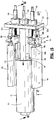
FIG. 1 is a perspective view of an adapter assembly, in accordance with an embodiment of the present disclosure, an exemplary electromechanical surgical device, an exemplary extension assembly, and an exemplary end effector; -
FIG. 2 is a perspective view of a drive assembly of the adapter assembly ofFIG. 1 ; -
FIG. 3 is a perspective view of the drive assembly ofFIG. 2 ; -
FIG. 4 is a perspective, separated view of the drive assembly ofFIG. 3 ; -
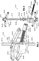
FIG. 5 is a perspective side view of a jackscrew assembly of the drive assembly ofFIG. 3 ; -
FIG. 6 is a perspective, separated side view of the jackscrew assembly ofFIG. 5 ; -
FIG. 7 is a cross-sectional top view of the drive assembly ofFIG. 3 taken along line 7-7 inFIG. 3 ; -
FIG. 8 is perspective view of the drive assembly ofFIG. 3 , with a first drive assembly in an extended position and each of a second and third drive member in a retracted position; -
FIG. 9 is a cross-sectional top view of the drive assembly ofFIG. 3 taken along line 9-9 ofFIG. 8 ; -
FIG. 10 is a cross-sectional side view of the drive assembly ofFIG. 3 taken along line 10-10 ofFIG. 9 ; -
FIG. 11 is the cross-sectional side view of the drive assembly ofFIG. 3 with the first drive sub-assembly in a retracted position; -
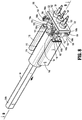
FIG. 12 is a perspective side view of the drive assembly ofFIG. 3 with the first drive sub-assembly in the extended position, the second drive sub-assembly in the retracted position, and the third drive sub-assembly in the extended position; -
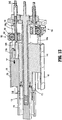
FIG. 13 is a cross-sectional top view of the drive assembly ofFIG. 3 taken along line 13-13 ofFIG. 12 ; -
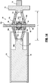
FIG. 14 is a cross-sectional side view taken along line 14-14 ofFIG. 13 ; -
FIG. 15 is a perspective top view of the drive assembly ofFIG. 3 with the first drive sub-assembly in the retracted position and each of the second and third drive subassemblies in the extended position; -
FIG. 16 is a cross-sectional top view of the drive assembly ofFIG. 3 taken along line 16-16 ofFIG. 15 ; and -
FIG. 17 is a cross-sectional side view of the drive assembly ofFIG. 3 taken along line 17-17 ofFIG. 15 . - Embodiments of the presently disclosed adapter assembly for surgical devices and/or handle assemblies are described in detail with reference to the drawings, in which like reference numerals designate identical or corresponding elements in each of the several views. As used herein the term "distal" refers to that portion of the adapter assembly or surgical device, or component thereof, farther from the user, while the term "proximal" refers to that portion of the adapter assembly or surgical device, or component thereof, closer to the user.
- With reference to
FIGS. 1 and 2 , an adapter assembly in accordance with an embodiment of the present disclosure, shown generally asadapter assembly 100, is configured for selective connection to a powered handheld electromechanical instrument shown, generally assurgical device 10. As illustrated inFIG. 1 , thesurgical device 10 is configured for selective connection with theadapter assembly 100, and, in turn, theadapter assembly 100 is configured for selective connection with anextension assembly 20. Theextension assembly 20 is configured for selective connection with a tool assembly or end effector,e.g. tool assembly 30, which may, in exemplary embodiments, include aloading unit 40 and ananvil assembly 50, for applying a circular array of staples (not shown) to tissue (not shown). - For a detailed description of the structure and function of an exemplary electromechanical instrument, please refer to commonly owned U.S. Pat. Appl. Publ. No.
2012/0253329 , the content of which is incorporated by reference herein in its entirety. - With continued reference to
FIG. 2 , theadapter assembly 100 includes aproximal portion 102 and adistal portion 104. Theproximal portion 102 includes arotation assembly 106 having a base 108, and arotation handle 110 rotatable relative to the base 108 about a longitudinal axis "x" of theadapter assembly 100. Thedistal portion 104 includes asleeve 112 fixedly secured to therotation handle 110. Rotation of the rotation handle 110 causes rotation of thesleeve 112. In this manner, an end effector, e.g. tool assembly 30 (FIG. 1 ), secured to thedistal portion 104 of theadapter assembly 100, or an end effector secured to an extension assembly, e.g., extension assembly 20 (FIG. 1 ), which is secured to thedistal portion 104 of theadapter assembly 100 is rotatable about the longitudinal axis "x" independent of movement of the surgical device 10 (FIG. 1 ) to whichadapter assembly 100 is attached. - Still referring to
FIG. 2 , alatch 114 is mounted to the rotation handle 110 and selectively secures the rotation handle 110 in a fixed orientation about the longitudinal axis "x". Thelatch 114 is configured to lock the rotation handle 110 relative to thebase 108. Proximal movement of thelatch 114, as indicated by arrow "A" inFIG. 2 , disengages thelatch 114 from the base 108 to permit rotation of the rotation handle 110 relative to thebase 106. For a detailed description of an exemplary rotation assembly and latch mechanism, please refer to commonly ownedU.S. Provisional Patent Application Serial No. 62/066,518 - Turning now to
FIGS. 3 and4 , the adapter assembly 100 (FIG. 2 ) includes adrive assembly 115 for effecting actuation of an end effector, e.g., tool assembly 30 (FIG. 1 ), secured to the distal portion 104 (FIG. 2 ) of the adapter assembly 100 (FIG. 1 ) and/or an end effector, e.g.,tool assembly 30, secured to an extension assembly, e.g., the extension assembly 20 (FIG. 1 ), which is secured to thedistal portion 104 of theadapter assembly 100. Thedrive assembly 115 is configured for transferring rotational motion from the surgical device 10 (FIG. 1 ) to linear motion to effect actuation of an end effector. More specifically, thedrive assembly 115 includes a drive coupling assembly 120 (FIG. 3 ), and first, second, andthird drive assemblies drive coupling assembly 120 for transferring rotation movement of respective first, second, and third drive shafts (not shown) of the surgical device 10 (FIG. 1 ) to respective first, second, and third linear movement for effecting first, second, and third actuations of an attached end effector, e.g. tool assembly 30 (FIG. 1 ), for performing respective first, second, and third operations of thetool assembly 30, e.g., clamping, stapling, and cutting. - The drive coupling assembly 120 (
FIG. 3 ) is operably supported within the base 108 (FIG. 1 ) of the rotation assembly 106 (FIG. 1 ) and includes athruster plate 122, and first, second, andthird connector members thruster plate 122. Thethruster plate 122 includes first andsecond support tabs FIG. 4 ; in phantom) extending distally therefrom. Proximal ends 124a, 126a, 128a of the respective first, second, andthird connector members FIG. 1 ). - The first drive assembly 130 (
FIG. 3 ) includes a drive screw 132 (FIG. 4 ) integrally formed with or fixedly coupled to thefirst connector member 124 of thedrive coupling assembly 120 and extending distally therefrom, and afirst drive member 134 longitudinally movable relative to thedrive screw 132. Specifically, aproximal end 134a of thefirst drive member 134 defines a threadedlongitudinal opening 135 through which thedrive screw 132 is received. Rotation of thedrive screw 132 in a first direction causes thefirst drive member 134 to move proximally, i.e., retract, and rotation of thedrive screw 132 in a second direction causes thefirst drive member 134 to move in a distal direction, i.e., advance. As will be described in further detail below, adistal end 134b of thefirst drive member 134 is operably connectable to a drive member (not shown) of an anvil assembly, e.g., theanvil assembly 50 - (
FIG. 1 ), of an end effector, e.g., tool assembly 30 (FIG. 1 ), to perform a first function, e.g., clamping of tissue. - Still referring to
FIGS. 3 and4 , the second drive assembly 140 (FIG. 3 ) includes asecond drive member 142, and afirst jackscrew assembly 150 operably disposed between thesecond connector member 126 of thedrive coupling assembly 120 and thesecond drive member 142. Thesecond drive member 142 includes atubular portion 144 and aguide portion 146 secured to thetubular portion 144 by aflange 145. Aconnector extension 146a extends proximally from theguide portion 146 and engages thefirst jackscrew assembly 150. Theguide portion 146 of thesecond drive member 142 is slidably disposed within afirst guide member 148. Although not shown, theguide member 148 is fixedly secured within the rotation handle 110 (FIG. 2 ) of the rotation assembly 106 (FIG. 2 ) and maintains thesecond drive member 142 in axial alignment with the longitudinal axis "x" (FIG. 2 ) of the adapter assembly 100 (FIG. 2 ) as operation of thefirst jackscrew assembly 150 longitudinally translates thesecond drive member 142. Thetubular portion 144 of thesecond drive member 142 defines alongitudinal opening 141 through which thefirst drive member 134 of thefirst drive assembly 130 is received. - With reference to
FIG. 5 , and particular reference toFIG. 6 , thefirst jackscrew assembly 150 includes ahousing 152, a drive shaft 154, a worm drive 156 (FIG. 6 ) on a distal end 154b (FIG. 6 ) of the drive shaft 154, ajackscrew 158, a worm gear 160 (FIG. 6 ) supported by first andsecond bearing members 160a (FIG. 6 ), 160b (FIG. 6 ), first andsecond jackscrew carriers 162, 164 (FIG. 6 ), and first and second link assemblies 166 (FIG. 6 ), 168 (FIG. 6 ). Aproximal end 154a of the drive shaft 154 is rotatably supported within the thruster plate 122 (FIG. 4 ) of the drive coupling assembly 120 (FIG. 3 ) by a bearingmember 155 and is operably connected to the second drive connector 126 (FIG. 3 ) of thedrive coupling assembly 120. More particularly, theproximal end 154a of the drive shaft 154 is slidably disposed and rotationally fixed within a longitudinal cavity 127 (FIG. 7 ) ofsecond drive connector 126 to accommodate longitudinal movement of thefirst jackscrew assembly 150 during actuation of thesecond drive assembly 140. The distal end 154b of the drive shaft 154, including the worm drive 156, is rotatably supported within thehousing 152. Thejackscrew 158 is rotatably received within and through thehousing 152 perpendicular to the drive shaft 154. The worm gear 160 is fixedly supported on thejackscrew 158 and operably engages the worm drive 156. As will be described in further detail below, rotation of the drive shaft 154 causes rotation of thejackscrew 158. - A
first end 158a of thejackscrew 158 includes a thread formed thereabout in a first direction, e.g., right-handed thread, and asecond end 158b of thejackscrew 158 includes a thread formed thereabout in a second direction, e.g., left-handed thread. Thefirst jackscrew carrier 162 is received about thefirst end 158a of thejackscrew 158, and thesecond jackscrew carrier 164 is received about thesecond end 158b of thejackscrew 158. The first andsecond jackscrew carriers jackscrew 158 in a first direction causes the first andsecond jackscrew carriers housing 152, and rotation of thejackscrew 158 in a second direction causes the first andsecond jackscrew carriers housing 152. - A
first link 166a of the first link assembly 166 connects thefirst jackscrew carrier 162 to the thruster plate 122 (FIG. 4 ), and asecond link 166b of the first link assembly 166 connects thefirst jackscrew carrier 162 to the guide portion 146 (FIG. 4 ) of the second drive member 142 (FIG. 4 ). More specifically, a proximal end of thefirst link 166a of the first link assembly 166 is pivotally secured to thefirst support tab 122a (FIG. 4 ) of thethruster plate 122, and a distal end of thefirst link 166a is pivotally secured to thefirst jackscrew carrier 162. A proximal end of thesecond link 166b of the first link assembly 166 is pivotally secured to thefirst jackscrew carrier 162, and a distal end of thesecond link 166b is pivotally secured to theconnector extension 146a of theguide portion 146 of thesecond drive member 142. - Similarly, a
first link 168a of the second link assembly 168 connects thefirst jackscrew carrier 162 to the thruster plate 122 (FIG. 4 ), and asecond link 168b of the second link assembly 168 connects thesecond jackscrew carrier 164 to theguide portion 146 of thesecond drive member 142. More specifically, a proximal end of thefirst link 168a of the second link assembly 168 is pivotally secured to thefirst support tab 122a (FIG. 4 ) of thethruster plate 122, and a distal end of thefirst link 168a is pivotally secured to thesecond jackscrew carrier 164. A proximal end of thesecond link 168b of the second link assembly 168 is pivotally secured to thesecond jackscrew carrier 164 and a distal end of thesecond link 168b is pivotally secured to theconnector extension 146a of theguide portion 146 of thesecond drive member 142. - As will be described in further detail below, when the first and
second jackscrew carriers jackscrew 158, the first andsecond links FIG. 10 ) therebetween and the proximal ends of thefirst links second links FIG. 10 ) therebetween. - When the first and
second jackscrew carriers jackscrew 158 adjacent thehousing 152, the first andsecond links FIG. 14 ) therebetween, and the proximal ends of thefirst links second links FIG. 14 ) therebetween. The second angle "α2" is greater than the first angle "α1" and the second distance "d2" is greater than the first distance "d1". In this manner, movement of the first andsecond jackscrew carriers jackscrew 158 to the position adjacent thehousing 152 increases the effective length of thejackscrew assembly 150. - With reference still to
FIGS. 3 and4 , thethird drive assembly 170 includes athird drive member 172, and asecond jackscrew assembly 180 operably disposed between thethird connector member 128 of thedrive coupling assembly 120 and thethird drive member 172. Thethird drive member 172 includes atubular portion 174, and aguide portion 176 secured to the tubular portion by aflange portion 175. Aconnector extension 176a extends proximally from theguide portion 176 and engages thesecond jackscrew assembly 180. Theguide portion 176 of thethird drive member 172 is slidably disposed within asecond guide member 178. Although not shown, theguide member 178 is fixedly secured within rotation handle 110 (FIG. 2 ) of the rotation assembly 106 (FIG. 2 ) and maintains thethird drive member 172 in axial alignment with the longitudinal axis "x" (FIG. 2 ) of the adapter assembly 100 (FIG. 2 ) as operation of thesecond jackscrew assembly 180 longitudinally translates thethird drive member 172. - The
tubular portion 174 of thethird drive member 172 defines alongitudinal opening 171 and alongitudinal slot 173 for accommodating longitudinal movement of thesecond drive member 142 of thesecond drive assembly 140 relative to thethird drive member 172. Specifically, thelongitudinal opening 171 in thetubular portion 174 of thethird drive member 172 receives thetubular portion 144 of thesecond drive member 142 and thelongitudinal slot 173 receives theflange 145 connecting theguide portion 146 of thesecond drive member 142 to thetubular portion 144. This configuration permits thetubular portion 144 of thesecond drive member 142 to be entirely received within thetubular portion 174 of thethird drive member 172, thereby reducing the overall length of the drive assembly 115 (FIG. 3 ). - The
second jackscrew assembly 180 is a mirror image of thefirst jackscrew assembly 150 and will also be described with reference toFIGS. 5 and 6 . Thesecond jackscrew assembly 180 includes ahousing 182, adrive shaft 184, a worm drive 186 on a distal end 184b of thedrive shaft 184, ajackscrew 188, a worm gear 190 supported by first andsecond bearing members second jackscrew carriers second link assemblies 196, 198. Aproximal end 184a of thedrive shaft 184 is rotatably supported within the thruster plate 122 (FIG. 3 ) of the drive coupling assembly 120 (FIG. 3 ) by a bearingmember 185 and is operably connected to the third drive connector 128 (FIG. 3 ) of the drive coupling assembly. More particularly, theproximal end 184a of thedrive shaft 184 is slidably disposed and rotationally fixed within a longitudinal cavity 129 (FIG. 7 ) ofthird drive connector 128 to accommodate longitudinal movement of thesecond jackscrew assembly 180 during actuation of thethird drive assembly 170. The distal end 174b of thedrive shaft 184, including the worm drive 186, is rotatably supported within thehousing 182. Thejackscrew 188 is rotatably received through thehousing 182 perpendicular to thedrive shaft 184. The worm gear 190 is supported on thejackscrew 188 and operably engages the worm drive 186. As will be described in further detail below, rotation of thedrive shaft 184 causes rotation of thejackscrew 188. - A
first end 188a of thejackscrew 188 includes a thread formed thereabout in a first direction, e.g., right-handed thread, and asecond end 188b of thejackscrew 188 includes a thread formed thereabout in a second direction, e.g., left-handed thread. Thefirst jackscrew carrier 192 is received about thefirst end 188a of thejackscrew 188, and thesecond jackscrew carrier 194 is received about thesecond end 188b of thejackscrew 188. The first andsecond jackscrew carriers jackscrew 188 in a first direction causes the first andsecond jackscrew carriers housing 182, and rotation of thejackscrew 188 in a second direction causes the first andsecond jackscrew carriers housing 182. - A
first link 196a of the first link assembly 196 connects thefirst jackscrew carrier 192 to the thruster plate 122 (FIG. 4 ), and asecond link 196b of the first link assembly 196 connects thefirst jackscrew carrier 192 to theguide portion 176 of thesecond drive member 172. Specifically, a proximal end of thefirst link 196a of the first link assembly 196 is pivotally secured to thesecond support tab 122b (FIG. 4 ) of thethruster plate 122, and a distal end of thefirst link 196a is pivotally secured to thefirst jackscrew carrier 192. A proximal end of thesecond link 196b of the first link assembly 196 is pivotally secured to thefirst jackscrew carrier 192, and a distal end of thesecond link 196b is pivotally secured to theconnector extension 176a of theguide portion 176 of thesecond drive member 172. - Similarly, a
first link 198a of thesecond link assembly 198 connects thefirst jackscrew carrier 192 to the thruster plate 122 (FIG. 4 ), and asecond link 198b of thesecond link assembly 198 connects thesecond jackscrew carrier 194 to theguide portion 176 of thesecond drive member 172. Specifically, a proximal end of thefirst link 198a of thesecond link assembly 198 is pivotally secured to thesecond support tab 122b of thethruster plate 122 and a distal end of thefirst link 198a is pivotally secured to thesecond jackscrew carrier 194. A proximal end of thesecond link 198b of thesecond link assembly 198 is pivotally secured to thesecond jackscrew carrier 194 and a distal end of thesecond link 198b is pivotally secured to theconnector extension 176a of theguide portion 176 of thesecond drive member 172. - As will be described in further detail below, when the first and
second jackscrew carriers jackscrew 188, the first andsecond links second link assemblies 196, 198 define the first angle "α1" (FIG. 10 ) therebetween and the proximal ends of thefirst links second link assemblies 196, 198 and the distal ends of thesecond links second link assemblies 196, 198 define the first distance "d1" (FIG. 10 ) therebetween. - When the first and
second jackscrew carriers jackscrew 158 adjacent thehousing 152, the first andsecond links first links second link assemblies 196, 198 and the distal ends of thesecond links second link assemblies 196, 198 define the second distance "d2" (FIG. 14 ) therebetween. As noted above with respect to thefirst jackscrew assembly 150, the second angle "α2" is greater than the first angle "α1" and the second distance "d2" is greater than the first distance "d1". In this manner, movement of the first andsecond jackscrew carriers jackscrew 188 to the position adjacent thehousing 182 increases the effective length of thejackscrew assembly 180. - Although shown being of substantially the same size and configuration, it is envisioned that the first and
second jackscrew assemblies jackscrews second jackscrew assemblies second jackscrew carriers - The operation of the
drive assembly 115 will now be described with reference toFIGS. 8-17 . Referring initially toFIGS. 8-10 , thedrive assembly 115 is shown with the first, second, andthird drive assemblies first drive member 134 of thefirst drive assembly 130 is in a distal-most position, and each of the second andthird drive members FIG. 1 ) of the tool assembly 30 (FIG. 1 ) is operably secured to thefirst drive member 134, in the first position, theanvil assembly 50 is spaced from the loading unit 40 (FIG. 1 ), as shown inFIG. 1 . - Although shown and described with the
first drive member 134 of thefirst drive assembly 130 in a distal-most position when thefirst drive assembly 130 is in the first position, it is envisioned that the operation of an end effector (not shown) secured to the adapter assembly 100 (FIG. 1 ) may require thefirst drive member 134 of thefirst drive assembly 130 to be in a proximal-most position, or at a location somewhere between the distal-most and proximal-most positions, when thefirst drive assembly 130 is in the first position. Similarly, although shown and described with the second andthird drive members third drive assemblies third drive assemblies FIG. 1 ) may require either or both of the second andthird drive members third drive assemblies third drive assemblies - With reference still to
FIGS. 8 and9 , when the second andthird drive assemblies second jackscrew assemblies third drive assemblies second links FIG. 6 ), 168 (FIG. 6 ) of thefirst jackscrew assembly 150 and the first andsecond links FIG. 6 ), 198 (FIG. 6 ) of thesecond jackscrew assembly 180 define the first angle "α1" (FIG. 10 ) therebetween. When the first andsecond jackscrew assemblies second jackscrew assemblies thruster plate 122 and the second andthird drive members - With particular reference to
FIG. 10 , the collapsed configuration of thesecond jackscrew assembly 180 will be described in detail. Although described with reference to thesecond jackscrew assembly 180, as noted above, the first andsecond jackscrew assemblies - In the collapsed configuration, the first and
second jackscrew carriers second ends jackscrew 188. Thesecond jackscrew assembly 180 is configured such that the proximal ends of thefirst links second link assemblies 196, 198, and the distal ends of thesecond links second link assemblies 196, 198 are positioned adjacent thehousing 152 of thejackscrew assembly 180 when the first andsecond carriers jackscrew 188. When in the collapsed configuration, the proximal ends of thefirst links second link assemblies 196, 198, respectively, and the distal ends of thesecond links second link assemblies 196, 198 define the distance "d1" therebetween. - Turning now to
FIG. 11 , movement of thefirst drive member 134 of thefirst drive assembly 130 from the first position to a second position is effected by operation of the surgical device 10 (FIG. 1 ). Specifically, rotation of a first drive shaft (not shown) of the surgical device 10 (FIG. 1 ) causes rotation of thefirst connector member 124 of thedrive coupling assembly 120. As thefirst connector member 124 rotates in a first direction, thedrive screw 132 secured to thefirst connector member 124 rotates in the same first direction within the threadedpassage 135 of thefirst drive member 134. Rotation of thedrive screw 132 within thethread passage 135 of thefirst drive member 134 causes thefirst drive member 134 to move proximally, i.e., retract, as indicated by arrow "B". Conversely, when thefirst connector member 124 is rotated in a second direction, thedrive screw 132 rotates in the second direction to cause thefirst drive member 134 to move distally, i.e., advance. - Proximal movement of the
first drive member 134 effectuates a first function of an end effector operably secured the adapter assembly 100 (FIG. 1 ). If, for example, the tool assembly 30 (FIG. 1 ) is operably secured to theadapter assembly 100 and the anvil assembly 50 (FIG. 1 ) is operably secured to thedistal end 134b of thefirst drive member 134, proximal movement of thefirst drive member 134 effectuates clamping of tissue between theanvil assembly 50 and the loading unit 40 (FIG. 1 ). - Turing now to
FIGS. 12-14 , movement of thethird drive assembly 170 from the first position to a second, extended position is effected by operation of the surgical device 10 (FIG. 1 ). Specifically, rotation of a third drive shaft (not shown) of the surgical device 10 (FIG. 1 ) causes rotation of thethird connector member 128 of the drive coupling assembly 120 (FIG. 3 ). As thethird connector member 128 rotates in a first direction, thesecond drive shaft 184 of thesecond jackscrew assembly 180 rotates in the same first direction. Rotation of thedrive shaft 184 causes rotation of thejackscrew 188 of thesecond jackscrew assembly 180. As thejackscrew 188 rotates, the first andsecond jackscrew carriers second jackscrew assembly 180 move from the position on the extreme ends of thejackscrew 188 towards each other and thehousing 182 of thesecond jackscrew assembly 180. - As the first and
second jackscrew carriers housing 182 the angle between the first andsecond links second link assemblies 196, 198 of thesecond jackscrew assembly 180 increases, thereby increasing the effective length of thesecond jackscrew assembly 180 and causing thethird drive member 172 of thethird drive assembly 170 to move distally, as indicated by arrow "C" inFIG. 13 . Conversely, when thethird connector member 128 is rotated in a second direction, thedrive shaft 182 rotates in the second direction to cause thejackscrew 188 to turn in the second direction which moves the first andsecond jackscrew carriers housing 172 thereby causing thethird drive member 174 to move proximally, i.e., retract. As noted above, theguide member 178 maintains thethird drive member 172 in axial alignment with the longitudinal axis "x" (FIG. 2 ) of the adapter assembly 100 (FIG. 2 ) during translation of thethird drive member 172. - Distal movement of the
third drive member 172 effectuates a second function of an end effector operably secured to the adapter assembly 100 (FIG. 2 ). If, for example, the tool assembly 30 (FIG. 1 ) is operably secured to theadapter assembly 100 and the loading unit 40 (FIG. 1 ) is operably secured to thethird drive member 172, distal movement of thethird drive member 172 advances a pusher assembly (not shown) to effectuate the stapling of tissue. - Turing now to
FIGS. 15-17 , movement of thesecond drive assembly 140 from the first position (FIG. 8 ) to a second, extended position is effected by operation of the surgical device 10 (FIG. 1 ). Specifically, rotation of the second shaft (not shown) of the surgical device 10 (FIG. 1 ) causes rotation of thesecond connector member 126 of thedrive coupling assembly 120. As thesecond connector member 126 rotates in a first direction, the first drive shaft 154 of thefirst jackscrew assembly 150 rotates in the same first direction. Rotation of the first drive shaft 154 causes rotation of thejackscrew 158 of thefirst jackscrew assembly 150. As thejackscrew 158 rotates, the first andsecond jackscrew carriers first jackscrew assembly 150 move from the position on the extreme ends of thejackscrew 158 towards each other and thehousing 152 of thefirst jackscrew assembly 150. - As the first and
second jackscrew carriers housing 152 the angle between the first andsecond links second jackscrew assembly 150 increases, thereby increasing the effective length of thesecond jackscrew assembly 150 and causing thesecond drive member 142 of thesecond drive assembly 140 to move distally, as indicated by arrow "D" inFIG. 16 . Conversely, when thesecond connector member 126 is rotated in a second direction, thedrive shaft 152 rotates in the second direction to cause thejackscrew 158 to turn in the second direction which moves the first andsecond jackscrew carriers housing 142 thereby causing thesecond drive member 142 to move proximally, i.e., retract. As noted above, theguide member 148 maintains thesecond drive member 142 in axial alignment with the longitudinal axis "x" (FIG. 2 ) of the adapter assembly 100 (FIG. 2 ) during translation of thesecond drive member 142. - Distal movement of the
second drive member 142 effectuates a third function. If, for example, the tool assembly 30 (FIG. 1 ) is operably secured to the adapter assembly 100 (FIG. 2 ) and the loading unit 40 (FIG. 1 ) is operably secured to thesecond drive member 142, distal movement of thesecond drive member 142 advances a knife assembly to effectuate the cutting of tissue. - Although the drive assembly 115 (
FIG. 3 ) of the adapter assembly 100 (FIG. 1 ) has been shown and described as relates to operation of the tool assembly 30 (FIG. 1 ) including the loading unit 40 (FIG. 1 ) and the anvil assembly 50 (FIG. 1 ), thedrive assembly 115 may be modified for operation with end effectors having different configurations. For example, thedrive assembly 115 may be modified for use with an end effector having only a single actuation, e.g., linear stapling. - Any of the components described herein may be fabricated from either metals, plastics, resins, composites or the like taking into consideration strength, durability, wearability, weight, resistance to corrosion, ease of manufacturing, cost of manufacturing, and the like.
- Persons skilled in the art will understand that the devices and methods specifically described herein and illustrated in the accompanying drawings are non-limiting exemplary embodiments. It is envisioned that the elements and features illustrated or described in connection with one exemplary embodiment may be combined with the elements and features of another without departing from the scope of the present disclosure. As well, one skilled in the art will appreciate further features and advantages of the disclosure based on the above-described embodiments. Accordingly, the disclosure is not to be limited by what has been particularly shown and described, except as indicated by the appended claims.
- The invention may be described by reference to the following numbered paragraphs:-
- 1. An adapter assembly for operably connecting an end effector to an electromechanical surgical instrument, the adapter assembly comprising:
- a drive coupling assembly;
- a first drive assembly operably connected to the drive coupling assembly, the first drive assembly including a drive screw;
- a second drive assembly operably connected to the drive coupling assembly, the second drive assembly including a first jackscrew assembly; and
- a third drive assembly operably connected to the drive coupling assembly, the third drive assembly including a second jackscrew assembly.
- 2. The adapter assembly of
paragraph 1, wherein the second drive assembly includes a second drive member operably connected to the first jackscrew assembly, the first jackscrew assembly being movable from a collapsed configuration to an extended configuration to move the second drive member from a proximal position to a distal position. - 3. The adapter assembly of paragraph 2, wherein the third drive assembly includes a third drive member operably connected to the second jackscrew assembly, the second jackscrew assembly being movable from a collapsed configuration to an extended configuration to move the third drive member from a proximal position to a distal position.
- 4. The adapter assembly of paragraph 3, wherein each of the second and third drive members includes a tubular portion, the tubular portion of the third drive member being slidably disposed within the tubular portion of the second drive member.
- 5. The adapter assembly of paragraph 4, wherein each of the second and third drive assemblies includes a guide member, and each of the second and third drive members include a guide portion slidably disposed within the respective guide members.
- 6. The adapter assembly of paragraph 4, wherein the first drive member is slidably disposed within the tubular portion of the second drive member.
- 7. The adapter assembly of
paragraph 1, wherein the drive coupling assembly includes a thruster plate and first, second, and third connector members. - 8. The adapter assembly of
paragraph 7, wherein the first connector member is operably connected to the drive screw, the second connector member is operably connected to the first jackscrew assembly, and the third connector member is operably connected to the second jackscrew assembly. - 9. The adapter assembly of
paragraph 1, wherein the first jackscrew assembly includes a housing, a drive shaft rotatably received within the housing, a worm drive operably disposed on the drive shaft, a jackscrew received within the housing and extending perpendicular to the drive shaft, a worm gear operably disposed about the jackscrew, first and second jackscrew carriers operably received on the jackscrew, and first and second link assemblies pivotally connected to the respective first and second jackscrew carriers. - 10. The adapter assembly of
paragraph 1, wherein the first jackscrew assembly includes first and second link assemblies, each of the first and second link assemblies including first and second links, the first and second links of each of the first and second link assemblies defining a first angle therebetween when the first jackscrew assembly is in a collapsed configuration. - 11. The adapter assembly of
paragraph 10, wherein the first and second links of each of the first and second link assemblies define a second angle therebetween when the first jackscrew assembly is in an extended configuration. - 12. The adapter assembly of paragraph 11, wherein the second angle is greater than the first angle.
- 13. The adapter assembly of paragraph 11, wherein the first jackscrew assembly defines a first effective length when the first jackscrew assembly is in the collapsed configuration and the first jackscrew assembly defines a second effective length when the first jackscrew assembly is in the extended configuration, the second effective length being greater than the first effective length.
- 14. The adapter assembly of
paragraph 1, further including a rotation assembly including a base and a rotation handle rotatably secured to the base. - 15. The adapter assembly of
paragraph 14, further including a sleeve fixedly secured to the rotation handle. - 16. The adapter assembly of paragraph 15, wherein the first, second, and third drive assemblies are secured within the base.
Claims (15)
- An adapter assembly for operably connecting an end effector to an electromechanical surgical instrument, the adapter assembly comprising:a drive coupling assembly;
a first drive assembly operably connected to the drive coupling assembly, the first drive assembly including a drive screw;
a second drive assembly operably connected to the drive coupling assembly, the second drive assembly including a first jackscrew assembly; and
a third drive assembly operably connected to the drive coupling assembly, the third drive assembly including a second jackscrew assembly. - The adapter assembly of claim 1, wherein the second drive assembly includes a second drive member operably connected to the first jackscrew assembly, the first jackscrew assembly being movable from a collapsed configuration to an extended configuration to move the second drive member from a proximal position to a distal position.
- The adapter assembly of claim 2, wherein the third drive assembly includes a third drive member operably connected to the second jackscrew assembly, the second jackscrew assembly being movable from a collapsed configuration to an extended configuration to move the third drive member from a proximal position to a distal position.
- The adapter assembly of claim 3, wherein each of the second and third drive members includes a tubular portion, the tubular portion of the third drive member being slidably disposed within the tubular portion of the second drive member.
- The adapter assembly of claim 4, wherein each of the second and third drive assemblies includes a guide member, and each of the second and third drive members include a guide portion slidably disposed within the respective guide members.
- The adapter assembly of claim 4, wherein the first drive member is slidably disposed within the tubular portion of the second drive member.
- The adapter assembly of any preceding claim, wherein the drive coupling assembly includes a thruster plate and first, second, and third connector members.
- The adapter assembly of claim 7, wherein the first connector member is operably connected to the drive screw, the second connector member is operably connected to the first jackscrew assembly, and the third connector member is operably connected to the second jackscrew assembly.
- The adapter assembly of any preceding claim, wherein the first jackscrew assembly includes a housing, a drive shaft rotatably received within the housing, a worm drive operably disposed on the drive shaft, a jackscrew received within the housing and extending perpendicular to the drive shaft, a worm gear operably disposed about the jackscrew, first and second jackscrew carriers operably received on the jackscrew, and first and second link assemblies pivotally connected to the respective first and second jackscrew carriers.
- The adapter assembly of any preceding claim, wherein the first jackscrew assembly includes first and second link assemblies, each of the first and second link assemblies including first and second links, the first and second links of each of the first and second link assemblies defining a first angle therebetween when the first jackscrew assembly is in a collapsed configuration.
- The adapter assembly of claim 10, wherein the first and second links of each of the first and second link assemblies define a second angle therebetween when the first jackscrew assembly is in an extended configuration.
- The adapter assembly of claim 11, wherein the second angle is greater than the first angle.
- The adapter assembly of claim 11 or claim 12, wherein the first jackscrew assembly defines a first effective length when the first jackscrew assembly is in the collapsed configuration and the first jackscrew assembly defines a second effective length when the first jackscrew assembly is in the extended configuration, the second effective length being greater than the first effective length.
- The adapter assembly of any preceding claim, further including a rotation assembly including a base and a rotation handle rotatably secured to the base.
- The adapter assembly of claim 14, further including a sleeve fixedly secured to the rotation handle; preferably wherein the first, second, and third drive assemblies are secured within the base.
Applications Claiming Priority (2)
| Application Number | Priority Date | Filing Date | Title |
|---|---|---|---|
| US201562265468P | 2015-12-10 | 2015-12-10 | |
| US15/363,074 US10433841B2 (en) | 2015-12-10 | 2016-11-29 | Adapter assembly for surgical device |
Publications (2)
| Publication Number | Publication Date |
|---|---|
| EP3178407A1 true EP3178407A1 (en) | 2017-06-14 |
| EP3178407B1 EP3178407B1 (en) | 2020-03-18 |
Family
ID=57539171
Family Applications (1)
| Application Number | Title | Priority Date | Filing Date |
|---|---|---|---|
| EP16203270.0A Active EP3178407B1 (en) | 2015-12-10 | 2016-12-09 | Adapter assembly for surgical device |
Country Status (2)
| Country | Link |
|---|---|
| US (1) | US10433841B2 (en) |
| EP (1) | EP3178407B1 (en) |
Families Citing this family (4)
| Publication number | Priority date | Publication date | Assignee | Title |
|---|---|---|---|---|
| ES2755485T3 (en) * | 2013-12-09 | 2020-04-22 | Covidien Lp | Adapter assembly for the interconnection of electromechanical surgical devices and surgical load units, and surgical systems thereof |
| US9918713B2 (en) * | 2013-12-09 | 2018-03-20 | Covidien Lp | Adapter assembly for interconnecting electromechanical surgical devices and surgical loading units, and surgical systems thereof |
| US11268607B1 (en) * | 2016-02-17 | 2022-03-08 | Helix Linear Technologies | Lead screw nuts having threads formed from different materials |
| USD1016599S1 (en) | 2017-02-17 | 2024-03-05 | Helix Linear Technologies | Nut |
Citations (5)
| Publication number | Priority date | Publication date | Assignee | Title |
|---|---|---|---|---|
| US20120253329A1 (en) | 2007-09-21 | 2012-10-04 | Michael Zemlok | Hand held surgical handle assembly, surgical adapters for use between surgical handle assembly and surgical end effectors, and methods of use |
| JP2014155826A (en) * | 2013-02-18 | 2014-08-28 | Covidien Lp | Apparatus for endoscopic procedures |
| CN203879441U (en) * | 2014-05-23 | 2014-10-15 | 什邡慧丰采油机械有限责任公司 | Jackscrew assembly structure for well head device |
| EP2889009A2 (en) * | 2013-12-09 | 2015-07-01 | Covidien LP | Adapter assembly for interconnecting electromechanical surgical devices and surgical loading units, and surgical systems thereof |
| EP2944276A1 (en) * | 2014-05-16 | 2015-11-18 | Covidien LP | Adaptor for surgical instrument for converting rotary input to linear output |
Family Cites Families (361)
| Publication number | Priority date | Publication date | Assignee | Title |
|---|---|---|---|---|
| US2669135A (en) * | 1953-05-13 | 1954-02-16 | Jack K Moore | Machine tool construction |
| US2777340A (en) | 1955-09-28 | 1957-01-15 | Leonard J Hettwer | Offset drilling attachment |
| US2957353A (en) | 1958-08-26 | 1960-10-25 | Teleflex Inc | Connector |
| US3111328A (en) | 1961-07-03 | 1963-11-19 | Rito Vincent L J Di | Multiuse adapter for manipulators |
| US3409090A (en) * | 1966-12-28 | 1968-11-05 | Paul C. Brown | Convertible power tool apparatus |
| US3734515A (en) | 1971-01-29 | 1973-05-22 | Thor Power Tool Co | Power wrench with interchangeable adapters |
| US3695058A (en) | 1971-05-26 | 1972-10-03 | Marvin W Keith Jr | Flexible link rotatable drive coupling |
| US3759336A (en) | 1972-01-21 | 1973-09-18 | D Marcovitz | Interchangeable power operated tools |
| US4090803A (en) * | 1977-03-01 | 1978-05-23 | Haley Ernest K | Drilling head system for I-beams |
| US4162399A (en) | 1977-09-16 | 1979-07-24 | Bei Electronics, Inc. | Optical encoder with fiber optics |
| US4203570A (en) * | 1978-08-23 | 1980-05-20 | The Western States Machine Company | Power-operated loading gate for centrifugal machines incorporating an auxiliary drive device |
| US4606343A (en) | 1980-08-18 | 1986-08-19 | United States Surgical Corporation | Self-powered surgical fastening instrument |
| US4705038A (en) | 1985-01-23 | 1987-11-10 | Dyonics, Inc. | Surgical system for powered instruments |
| US4722685A (en) | 1985-05-30 | 1988-02-02 | Estrada Juan M De | Tool for adapting a portable lathe to treat the back molar teeth of horses |
| US4823807A (en) | 1988-02-11 | 1989-04-25 | Board Of Regents, Univ. Of Texas System | Device for non-invasive diagnosis and monitoring of articular and periarticular pathology |
| US4874181A (en) | 1988-05-31 | 1989-10-17 | Hsu Shing Wang | Coupling member for securing a drilling head to the rotatable rod of a pneumatic tool body |
| US5301061A (en) | 1989-07-27 | 1994-04-05 | Olympus Optical Co., Ltd. | Endoscope system |
| US5152744A (en) | 1990-02-07 | 1992-10-06 | Smith & Nephew Dyonics | Surgical instrument |
| JP3034019B2 (en) | 1990-11-26 | 2000-04-17 | 旭光学工業株式会社 | Endoscope tip |
| US5129570A (en) | 1990-11-30 | 1992-07-14 | Ethicon, Inc. | Surgical stapler |
| US5413267A (en) | 1991-05-14 | 1995-05-09 | United States Surgical Corporation | Surgical stapler with spent cartridge sensing and lockout means |
| US5129118A (en) | 1991-07-29 | 1992-07-14 | Walmesley Mark W | Accessory tool apparatus for use on power drills |
| US5478003A (en) | 1991-10-18 | 1995-12-26 | United States Surgical Corporation | Surgical apparatus |
| US5326013A (en) | 1991-10-18 | 1994-07-05 | United States Surgical Corporation | Self contained gas powered surgical apparatus |
| US5312023A (en) | 1991-10-18 | 1994-05-17 | United States Surgical Corporation | Self contained gas powered surgical apparatus |
| US5197649A (en) | 1991-10-29 | 1993-03-30 | The Trustees Of Columbia University In The City Of New York | Gastrointestinal endoscoptic stapler |
| US5383874A (en) | 1991-11-08 | 1995-01-24 | Ep Technologies, Inc. | Systems for identifying catheters and monitoring their use |
| US5433721A (en) | 1992-01-17 | 1995-07-18 | Ethicon, Inc. | Endoscopic instrument having a torsionally stiff drive shaft for applying fasteners to tissue |
| US5383880A (en) | 1992-01-17 | 1995-01-24 | Ethicon, Inc. | Endoscopic surgical system with sensing means |
| US5350355A (en) | 1992-02-14 | 1994-09-27 | Automated Medical Instruments, Inc. | Automated surgical instrument |
| US5389098A (en) | 1992-05-19 | 1995-02-14 | Olympus Optical Co., Ltd. | Surgical device for stapling and/or fastening body tissues |
| US5658300A (en) | 1992-06-04 | 1997-08-19 | Olympus Optical Co., Ltd. | Tissue fixing surgical instrument, tissue-fixing device, and method of fixing tissues |
| US5609560A (en) | 1992-08-19 | 1997-03-11 | Olympus Optical Co., Ltd. | Medical operation device control system for controlling a operation devices accessed respectively by ID codes |
| US5431323A (en) | 1992-10-09 | 1995-07-11 | Ethicon, Inc. | Endoscopic surgical instrument with pivotable and rotatable staple cartridge |
| US5626587A (en) | 1992-10-09 | 1997-05-06 | Ethicon Endo-Surgery, Inc. | Method for operating a surgical instrument |
| US5662662A (en) | 1992-10-09 | 1997-09-02 | Ethicon Endo-Surgery, Inc. | Surgical instrument and method |
| US5601224A (en) | 1992-10-09 | 1997-02-11 | Ethicon, Inc. | Surgical instrument |
| US5400267A (en) | 1992-12-08 | 1995-03-21 | Hemostatix Corporation | Local in-device memory feature for electrically powered medical equipment |
| US5540706A (en) | 1993-01-25 | 1996-07-30 | Aust; Gilbert M. | Surgical instrument |
| US5540375A (en) | 1993-04-20 | 1996-07-30 | United States Surgical Corporation | Endoscopic stapler |
| US5467911A (en) | 1993-04-27 | 1995-11-21 | Olympus Optical Co., Ltd. | Surgical device for stapling and fastening body tissues |
| CA2124109A1 (en) | 1993-05-24 | 1994-11-25 | Mark T. Byrne | Endoscopic surgical instrument with electromagnetic sensor |
| US5542594A (en) | 1993-10-06 | 1996-08-06 | United States Surgical Corporation | Surgical stapling apparatus with biocompatible surgical fabric |
| US5487499A (en) | 1993-10-08 | 1996-01-30 | United States Surgical Corporation | Surgical apparatus for applying surgical fasteners including a counter |
| US5476379A (en) | 1993-11-04 | 1995-12-19 | Disel; Jimmy D. | Illumination system and connector assembly for a dental handpiece |
| AU1558995A (en) | 1994-01-04 | 1995-08-01 | Alpha Surgical Technologies, Inc. | Stapling device |
| US6165169A (en) | 1994-03-04 | 2000-12-26 | Ep Technologies, Inc. | Systems and methods for identifying the physical, mechanical, and functional attributes of multiple electrode arrays |
| US5526822A (en) | 1994-03-24 | 1996-06-18 | Biopsys Medical, Inc. | Method and apparatus for automated biopsy and collection of soft tissue |
| US5529235A (en) | 1994-04-28 | 1996-06-25 | Ethicon Endo-Surgery, Inc. | Identification device for surgical instrument |
| US5553675A (en) | 1994-06-10 | 1996-09-10 | Minnesota Mining And Manufacturing Company | Orthopedic surgical device |
| US5779130A (en) | 1994-08-05 | 1998-07-14 | United States Surgical Corporation | Self-contained powered surgical apparatus |
| EP0699418A1 (en) | 1994-08-05 | 1996-03-06 | United States Surgical Corporation | Self-contained powered surgical apparatus |
| EP0705571A1 (en) | 1994-10-07 | 1996-04-10 | United States Surgical Corporation | Self-contained powered surgical apparatus |
| US5549637A (en) | 1994-11-10 | 1996-08-27 | Crainich; Lawrence | Articulated medical instrument |
| US5868760A (en) | 1994-12-07 | 1999-02-09 | Mcguckin, Jr.; James F. | Method and apparatus for endolumenally resectioning tissue |
| US5632432A (en) | 1994-12-19 | 1997-05-27 | Ethicon Endo-Surgery, Inc. | Surgical instrument |
| US5704534A (en) | 1994-12-19 | 1998-01-06 | Ethicon Endo-Surgery, Inc. | Articulation assembly for surgical instruments |
| US5713505A (en) | 1996-05-13 | 1998-02-03 | Ethicon Endo-Surgery, Inc. | Articulation transmission mechanism for surgical instruments |
| US6321855B1 (en) | 1994-12-29 | 2001-11-27 | George Edward Barnes | Anti-vibration adaptor |
| US5649956A (en) | 1995-06-07 | 1997-07-22 | Sri International | System and method for releasably holding a surgical instrument |
| US5762256A (en) | 1995-08-28 | 1998-06-09 | United States Surgical Corporation | Surgical stapler |
| US5782396A (en) | 1995-08-28 | 1998-07-21 | United States Surgical Corporation | Surgical stapler |
| US6032849A (en) | 1995-08-28 | 2000-03-07 | United States Surgical | Surgical stapler |
| WO1997011634A1 (en) | 1995-09-15 | 1997-04-03 | Robert Lee Thompson | Surgical/diagnostic imaging device |
| US7141049B2 (en) | 1999-03-09 | 2006-11-28 | Thermage, Inc. | Handpiece for treatment of tissue |
| US6010054A (en) | 1996-02-20 | 2000-01-04 | Imagyn Medical Technologies | Linear stapling instrument with improved staple cartridge |
| US6699177B1 (en) | 1996-02-20 | 2004-03-02 | Computer Motion, Inc. | Method and apparatus for performing minimally invasive surgical procedures |
| US5820009A (en) | 1996-02-20 | 1998-10-13 | Richard-Allan Medical Industries, Inc. | Articulated surgical instrument with improved jaw closure mechanism |
| US6119913A (en) | 1996-06-14 | 2000-09-19 | Boston Scientific Corporation | Endoscopic stapler |
| US6017354A (en) | 1996-08-15 | 2000-01-25 | Stryker Corporation | Integrated system for powered surgical tools |
| US6129547A (en) | 1997-05-06 | 2000-10-10 | Ballard Medical Products | Oral care system |
| WO1999007441A1 (en) | 1997-08-11 | 1999-02-18 | Mayer Paul W | Motorized motion-canceling suture tool holder |
| US6434507B1 (en) | 1997-09-05 | 2002-08-13 | Surgical Navigation Technologies, Inc. | Medical instrument and method for use with computer-assisted image guided surgery |
| US5865361A (en) | 1997-09-23 | 1999-02-02 | United States Surgical Corporation | Surgical stapling apparatus |
| US5863159A (en) | 1997-12-12 | 1999-01-26 | Lasko; Leonard J. | Drill angle attachment coupling |
| CA2321488C (en) | 1998-02-19 | 2008-02-12 | California Institute Of Technology | Apparatus and method for providing spherical viewing during endoscopic procedures |
| US6239732B1 (en) | 1998-04-13 | 2001-05-29 | Dallas Semiconductor Corporation | One-wire device with A-to-D converter |
| US6126058A (en) | 1998-06-19 | 2000-10-03 | Scimed Life Systems, Inc. | Method and device for full thickness resectioning of an organ |
| US6256859B1 (en) | 1998-09-25 | 2001-07-10 | Sherwood Services Ag | Method of manufacturing an aspiring tool |
| US5993454A (en) | 1998-09-29 | 1999-11-30 | Stryker Corporation | Drill attachment for a surgical drill |
| US7238021B1 (en) | 1998-12-03 | 2007-07-03 | Johnson Gary E | Powered cutting surface with protective guard for equine teeth |
| US6860892B1 (en) | 1999-05-28 | 2005-03-01 | General Surgical Innovations, Inc. | Specially shaped balloon device for use in surgery and method of use |
| US6264087B1 (en) | 1999-07-12 | 2001-07-24 | Powermed, Inc. | Expanding parallel jaw device for use with an electromechanical driver device |
| US7951071B2 (en) | 1999-06-02 | 2011-05-31 | Tyco Healthcare Group Lp | Moisture-detecting shaft for use with an electro-mechanical surgical device |
| US7032798B2 (en) | 1999-06-02 | 2006-04-25 | Power Medical Interventions, Inc. | Electro-mechanical surgical device |
| US6491201B1 (en) | 2000-02-22 | 2002-12-10 | Power Medical Interventions, Inc. | Fluid delivery mechanism for use with anastomosing, stapling, and resecting instruments |
| US8025199B2 (en) | 2004-02-23 | 2011-09-27 | Tyco Healthcare Group Lp | Surgical cutting and stapling device |
| US6716233B1 (en) | 1999-06-02 | 2004-04-06 | Power Medical Interventions, Inc. | Electromechanical driver and remote surgical instrument attachment having computer assisted control capabilities |
| US6443973B1 (en) | 1999-06-02 | 2002-09-03 | Power Medical Interventions, Inc. | Electromechanical driver device for use with anastomosing, stapling, and resecting instruments |
| US6315184B1 (en) | 1999-06-02 | 2001-11-13 | Powermed, Inc. | Stapling device for use with an electromechanical driver device for use with anastomosing, stapling, and resecting instruments |
| US6793652B1 (en) | 1999-06-02 | 2004-09-21 | Power Medical Interventions, Inc. | Electro-mechanical surgical device |
| US8241322B2 (en) | 2005-07-27 | 2012-08-14 | Tyco Healthcare Group Lp | Surgical device |
| US6981941B2 (en) | 1999-06-02 | 2006-01-03 | Power Medical Interventions | Electro-mechanical surgical device |
| US6451007B1 (en) | 1999-07-29 | 2002-09-17 | Dale E. Koop | Thermal quenching of tissue |
| US6611793B1 (en) | 1999-09-07 | 2003-08-26 | Scimed Life Systems, Inc. | Systems and methods to identify and disable re-use single use devices based on detecting environmental changes |
| US6368324B1 (en) | 1999-09-24 | 2002-04-09 | Medtronic Xomed, Inc. | Powered surgical handpiece assemblies and handpiece adapter assemblies |
| US7803151B2 (en) | 2001-12-04 | 2010-09-28 | Power Medical Interventions, Llc | System and method for calibrating a surgical instrument |
| US6488197B1 (en) | 2000-02-22 | 2002-12-03 | Power Medical Interventions, Inc. | Fluid delivery device for use with anastomosing resecting and stapling instruments |
| US8016855B2 (en) | 2002-01-08 | 2011-09-13 | Tyco Healthcare Group Lp | Surgical device |
| US7770773B2 (en) | 2005-07-27 | 2010-08-10 | Power Medical Interventions, Llc | Surgical device |
| US6533157B1 (en) | 2000-02-22 | 2003-03-18 | Power Medical Interventions, Inc. | Tissue stapling attachment for use with an electromechanical driver device |
| US6348061B1 (en) | 2000-02-22 | 2002-02-19 | Powermed, Inc. | Vessel and lumen expander attachment for use with an electromechanical driver device |
| JP3897962B2 (en) | 2000-07-19 | 2007-03-28 | 株式会社モリタ製作所 | Identification-type instrument body, identification-type adapter, identification-type tube, and medical device using these |
| EP1313401A4 (en) | 2000-08-30 | 2006-09-20 | Cerebral Vascular Applic Inc | MEDICAL INSTRUMENT |
| US6817508B1 (en) | 2000-10-13 | 2004-11-16 | Tyco Healthcare Group, Lp | Surgical stapling device |
| US6716226B2 (en) | 2001-06-25 | 2004-04-06 | Inscope Development, Llc | Surgical clip |
| US20050004559A1 (en) | 2003-06-03 | 2005-01-06 | Senorx, Inc. | Universal medical device control console |
| US8313496B2 (en) | 2001-02-02 | 2012-11-20 | Lsi Solutions, Inc. | System for endoscopic suturing |
| US7699835B2 (en) | 2001-02-15 | 2010-04-20 | Hansen Medical, Inc. | Robotically controlled surgical instruments |
| US7905897B2 (en) | 2001-03-14 | 2011-03-15 | Tyco Healthcare Group Lp | Trocar device |
| ES2381407T3 (en) | 2001-04-20 | 2012-05-28 | Tyco Healthcare Group Lp | Bipolar or ultrasonic surgical device |
| EP2330522A1 (en) | 2001-06-20 | 2011-06-08 | Tyco Healthcare Group LP | Method and system for integrated medical tracking |
| EP3158942B1 (en) | 2001-06-22 | 2018-08-08 | Covidien LP | Electro-mechanical surgical device |
| US7044911B2 (en) | 2001-06-29 | 2006-05-16 | Philometron, Inc. | Gateway platform for biological monitoring and delivery of therapeutic compounds |
| US20030093103A1 (en) | 2001-08-08 | 2003-05-15 | Don Malackowski | Surgical tool system with components that perform inductive data transfer |
| DE10147145C2 (en) | 2001-09-25 | 2003-12-18 | Kunz Reiner | Multi-function instrument for micro-invasive surgery |
| EP2347722B1 (en) | 2001-10-05 | 2014-09-17 | Covidien LP | Surgical stapling device |
| US10285694B2 (en) | 2001-10-20 | 2019-05-14 | Covidien Lp | Surgical stapler with timer and feedback display |
| US7464847B2 (en) | 2005-06-03 | 2008-12-16 | Tyco Healthcare Group Lp | Surgical stapler with timer and feedback display |
| US6783533B2 (en) | 2001-11-21 | 2004-08-31 | Sythes Ag Chur | Attachable/detachable reaming head for surgical reamer |
| IL148702A (en) | 2002-03-14 | 2008-04-13 | Innoventions Inc | Insertion and retrieval system for inflatable devices |
| EP1496805B1 (en) | 2002-04-25 | 2012-01-11 | Tyco Healthcare Group LP | Surgical instruments including micro-electromechanical systems (mems) |
| CA2489727C (en) | 2002-06-14 | 2011-04-26 | Power Medical Interventions, Inc. | Surgical device |
| US20030038938A1 (en) | 2002-06-20 | 2003-02-27 | Jung Wayne D. | Apparatus and method for measuring optical characteristics of an object or material |
| US8182494B1 (en) | 2002-07-31 | 2012-05-22 | Cardica, Inc. | Minimally-invasive surgical system |
| US6645218B1 (en) | 2002-08-05 | 2003-11-11 | Endius Incorporated | Surgical instrument |
| US20040176751A1 (en) | 2002-08-14 | 2004-09-09 | Endovia Medical, Inc. | Robotic medical instrument system |
| EP1545289B1 (en) | 2002-09-30 | 2010-04-28 | Power Medical Interventions, LLC | Self-contained sterilizable surgical system |
| CA2500785C (en) | 2002-10-04 | 2011-04-26 | Philip C. Roy | Pneumatic powered surgical stapling device |
| US7559927B2 (en) | 2002-12-20 | 2009-07-14 | Medtronic Xomed, Inc. | Surgical instrument with telescoping attachment |
| JP2004208922A (en) | 2002-12-27 | 2004-07-29 | Olympus Corp | Medical apparatus, medical manipulator and control process for medical apparatus |
| US7044352B2 (en) | 2003-05-20 | 2006-05-16 | Ethicon Endo-Surgery, Inc. | Surgical stapling instrument having a single lockout mechanism for prevention of firing |
| US7380696B2 (en) | 2003-05-20 | 2008-06-03 | Ethicon Endo-Surgery, Inc. | Articulating surgical stapling instrument incorporating a two-piece E-beam firing mechanism |
| US7380695B2 (en) | 2003-05-20 | 2008-06-03 | Ethicon Endo-Surgery, Inc. | Surgical stapling instrument having a single lockout mechanism for prevention of firing |
| US7140528B2 (en) | 2003-05-20 | 2006-11-28 | Ethicon Endo-Surgery, Inc. | Surgical stapling instrument having an electroactive polymer actuated single lockout mechanism for prevention of firing |
| US20070084897A1 (en) | 2003-05-20 | 2007-04-19 | Shelton Frederick E Iv | Articulating surgical stapling instrument incorporating a two-piece e-beam firing mechanism |
| US6988649B2 (en) | 2003-05-20 | 2006-01-24 | Ethicon Endo-Surgery, Inc. | Surgical stapling instrument having a spent cartridge lockout |
| US7143923B2 (en) | 2003-05-20 | 2006-12-05 | Ethicon Endo-Surgery, Inc. | Surgical stapling instrument having a firing lockout for an unclosed anvil |
| US8365633B2 (en) | 2003-05-21 | 2013-02-05 | The Johns Hopkins University | Devices, systems and methods for minimally invasive surgery of the throat and other portions of mammalian body |
| ES2550808T3 (en) | 2003-06-20 | 2015-11-12 | Covidien Lp | Surgical stapling instrument |
| US6981628B2 (en) | 2003-07-09 | 2006-01-03 | Ethicon Endo-Surgery, Inc. | Surgical instrument with a lateral-moving articulation control |
| US7055731B2 (en) | 2003-07-09 | 2006-06-06 | Ethicon Endo-Surgery Inc. | Surgical stapling instrument incorporating a tapered firing bar for increased flexibility around the articulation joint |
| US6964363B2 (en) | 2003-07-09 | 2005-11-15 | Ethicon Endo-Surgery, Inc. | Surgical stapling instrument having articulation joint support plates for supporting a firing bar |
| US7111769B2 (en) | 2003-07-09 | 2006-09-26 | Ethicon Endo-Surgery, Inc. | Surgical instrument incorporating an articulation mechanism having rotation about the longitudinal axis |
| JP4398813B2 (en) | 2003-07-18 | 2010-01-13 | ヤーマン株式会社 | Skin care equipment |
| US6905057B2 (en) | 2003-09-29 | 2005-06-14 | Ethicon Endo-Surgery, Inc. | Surgical stapling instrument incorporating a firing mechanism having a linked rack transmission |
| US6959852B2 (en) | 2003-09-29 | 2005-11-01 | Ethicon Endo-Surgery, Inc. | Surgical stapling instrument with multistroke firing incorporating an anti-backup mechanism |
| US7364061B2 (en) | 2003-09-29 | 2008-04-29 | Ethicon Endo-Surgery, Inc. | Surgical stapling instrument incorporating a multistroke firing position indicator and retraction mechanism |
| US20090090763A1 (en) | 2007-10-05 | 2009-04-09 | Tyco Healthcare Group Lp | Powered surgical stapling device |
| US8806973B2 (en) | 2009-12-02 | 2014-08-19 | Covidien Lp | Adapters for use between surgical handle assembly and surgical end effector |
| US8770459B2 (en) | 2003-10-17 | 2014-07-08 | Covidien Lp | Surgical stapling device with independent tip rotation |
| US10105140B2 (en) | 2009-11-20 | 2018-10-23 | Covidien Lp | Surgical console and hand-held surgical device |
| US10022123B2 (en) | 2012-07-09 | 2018-07-17 | Covidien Lp | Surgical adapter assemblies for use between surgical handle assembly and surgical end effectors |
| US8968276B2 (en) | 2007-09-21 | 2015-03-03 | Covidien Lp | Hand held surgical handle assembly, surgical adapters for use between surgical handle assembly and surgical end effectors, and methods of use |
| US10588629B2 (en) | 2009-11-20 | 2020-03-17 | Covidien Lp | Surgical console and hand-held surgical device |
| US7172415B2 (en) | 2003-11-22 | 2007-02-06 | Flexi-Float, Llc | Equine dental grinding apparatus |
| DE10357105B3 (en) | 2003-12-06 | 2005-04-07 | Richard Wolf Gmbh | Medical instrument for medical applications comprises an insert and a handle detachedly connected to each other |
| ES2286725T3 (en) | 2004-02-17 | 2007-12-01 | Tyco Healthcare Group Lp | SURGICAL STAPLING APPARATUS. |
| EP1723913A1 (en) | 2004-03-10 | 2006-11-22 | Olympus Corporation | Treatment tool for surgery |
| US7059508B2 (en) | 2004-06-30 | 2006-06-13 | Ethicon Endo-Surgery, Inc. | Surgical stapling instrument incorporating an uneven multistroke firing mechanism having a rotary transmission |
| US20060142744A1 (en) | 2004-07-27 | 2006-06-29 | Dmitri Boutoussov | Identification connector for a medical laser handpiece |
| US7487899B2 (en) | 2004-07-28 | 2009-02-10 | Ethicon Endo-Surgery, Inc. | Surgical instrument incorporating EAP complete firing system lockout mechanism |
| US7143926B2 (en) | 2005-02-07 | 2006-12-05 | Ethicon Endo-Surgery, Inc. | Surgical stapling instrument incorporating a multi-stroke firing mechanism with return spring rotary manual retraction system |
| US7143925B2 (en) | 2004-07-28 | 2006-12-05 | Ethicon Endo-Surgery, Inc. | Surgical instrument incorporating EAP blocking lockout mechanism |
| US7147138B2 (en) | 2004-07-28 | 2006-12-12 | Ethicon Endo-Surgery, Inc. | Surgical stapling instrument having an electroactive polymer actuated buttress deployment mechanism |
| US7947034B2 (en) | 2004-07-30 | 2011-05-24 | Tyco Healthcare Group Lp | Flexible shaft extender and method of using same |
| US7922719B2 (en) | 2004-10-06 | 2011-04-12 | Biodynamics, Llc | Adjustable angle pawl handle for surgical instruments |
| JP5009159B2 (en) | 2004-10-08 | 2012-08-22 | エシコン・エンド−サージェリィ・インコーポレイテッド | Ultrasonic surgical instrument |
| US20060142656A1 (en) | 2004-12-09 | 2006-06-29 | Don Malackowski | Wireless system for providing instrument and implant data to a surgical navigation unit |
| US20060142740A1 (en) | 2004-12-29 | 2006-06-29 | Sherman Jason T | Method and apparatus for performing a voice-assisted orthopaedic surgical procedure |
| US7822458B2 (en) | 2005-05-19 | 2010-10-26 | The Johns Hopkins University | Distal bevel-tip needle control device and algorithm |
| EP1736112B1 (en) | 2005-06-20 | 2011-08-17 | Heribert Schmid | Medical device |
| US8579176B2 (en) | 2005-07-26 | 2013-11-12 | Ethicon Endo-Surgery, Inc. | Surgical stapling and cutting device and method for using the device |
| US8573462B2 (en) | 2006-05-19 | 2013-11-05 | Ethicon Endo-Surgery, Inc. | Electrical surgical instrument with optimized power supply and drive |
| US8627995B2 (en) | 2006-05-19 | 2014-01-14 | Ethicon Endo-Sugery, Inc. | Electrically self-powered surgical instrument with cryptographic identification of interchangeable part |
| JP5043842B2 (en) | 2005-07-27 | 2012-10-10 | タイコ ヘルスケア グループ リミテッド パートナーシップ | Shaft for electromechanical surgical device |
| US20070029363A1 (en) | 2005-08-07 | 2007-02-08 | Sergey Popov | Surgical apparatus with remote drive |
| US8348855B2 (en) | 2005-08-29 | 2013-01-08 | Galil Medical Ltd. | Multiple sensor device for measuring tissue temperature during thermal treatment |
| US7407078B2 (en) | 2005-09-21 | 2008-08-05 | Ehthicon Endo-Surgery, Inc. | Surgical stapling instrument having force controlled spacing end effector |
| CA2561473C (en) | 2005-09-30 | 2014-07-29 | Ethicon Endo-Surgery, Inc. | Electroactive polymer-based actuation mechanism for linear surgical stapler |
| US7641091B2 (en) | 2005-10-04 | 2010-01-05 | Tyco Healthcare Group Lp | Staple drive assembly |
| US20070102472A1 (en) | 2005-11-04 | 2007-05-10 | Ethicon Endo-Surgery, Inc. | Electrosurgical stapling instrument with disposable severing / stapling unit |
| US7328828B2 (en) | 2005-11-04 | 2008-02-12 | Ethicon Endo-Surgery, Inc, | Lockout mechanisms and surgical instruments including same |
| US7673780B2 (en) | 2005-11-09 | 2010-03-09 | Ethicon Endo-Surgery, Inc. | Articulation joint with improved moment arm extension for articulating an end effector of a surgical instrument |
| US20070106317A1 (en) | 2005-11-09 | 2007-05-10 | Shelton Frederick E Iv | Hydraulically and electrically actuated articulation joints for surgical instruments |
| US7799039B2 (en) | 2005-11-09 | 2010-09-21 | Ethicon Endo-Surgery, Inc. | Surgical instrument having a hydraulically actuated end effector |
| US7246734B2 (en) | 2005-12-05 | 2007-07-24 | Ethicon Endo-Surgery, Inc. | Rotary hydraulic pump actuated multi-stroke surgical instrument |
| US8672922B2 (en) | 2005-12-20 | 2014-03-18 | Intuitive Surgical Operations, Inc. | Wireless communication in a robotic surgical system |
| US7481824B2 (en) | 2005-12-30 | 2009-01-27 | Ethicon Endo-Surgery, Inc. | Surgical instrument with bending articulation controlled articulation pivot joint |
| US7670334B2 (en) | 2006-01-10 | 2010-03-02 | Ethicon Endo-Surgery, Inc. | Surgical instrument having an articulating end effector |
| US8186555B2 (en) | 2006-01-31 | 2012-05-29 | Ethicon Endo-Surgery, Inc. | Motor-driven surgical cutting and fastening instrument with mechanical closure system |
| US7416101B2 (en) | 2006-01-31 | 2008-08-26 | Ethicon Endo-Surgery, Inc. | Motor-driven surgical cutting and fastening instrument with loading force feedback |
| US20070175951A1 (en) | 2006-01-31 | 2007-08-02 | Shelton Frederick E Iv | Gearing selector for a powered surgical cutting and fastening instrument |
| US7568603B2 (en) | 2006-01-31 | 2009-08-04 | Ethicon Endo-Surgery, Inc. | Motor-driven surgical cutting and fastening instrument with articulatable end effector |
| US7575144B2 (en) | 2006-01-31 | 2009-08-18 | Ethicon Endo-Surgery, Inc. | Surgical fastener and cutter with single cable actuator |
| US7644848B2 (en) | 2006-01-31 | 2010-01-12 | Ethicon Endo-Surgery, Inc. | Electronic lockouts and surgical instrument including same |
| US20070175950A1 (en) | 2006-01-31 | 2007-08-02 | Shelton Frederick E Iv | Disposable staple cartridge having an anvil with tissue locator for use with a surgical cutting and fastening instrument and modular end effector system therefor |
| US7766210B2 (en) | 2006-01-31 | 2010-08-03 | Ethicon Endo-Surgery, Inc. | Motor-driven surgical cutting and fastening instrument with user feedback system |
| US7464849B2 (en) | 2006-01-31 | 2008-12-16 | Ethicon Endo-Surgery, Inc. | Electro-mechanical surgical instrument with closure system and anvil alignment components |
| US20070175955A1 (en) | 2006-01-31 | 2007-08-02 | Shelton Frederick E Iv | Surgical cutting and fastening instrument with closure trigger locking mechanism |
| US7422139B2 (en) | 2006-01-31 | 2008-09-09 | Ethicon Endo-Surgery, Inc. | Motor-driven surgical cutting fastening instrument with tactile position feedback |
| US7845537B2 (en) | 2006-01-31 | 2010-12-07 | Ethicon Endo-Surgery, Inc. | Surgical instrument having recording capabilities |
| US8708213B2 (en) | 2006-01-31 | 2014-04-29 | Ethicon Endo-Surgery, Inc. | Surgical instrument having a feedback system |
| US7464846B2 (en) | 2006-01-31 | 2008-12-16 | Ethicon Endo-Surgery, Inc. | Surgical instrument having a removable battery |
| US7770775B2 (en) | 2006-01-31 | 2010-08-10 | Ethicon Endo-Surgery, Inc. | Motor-driven surgical cutting and fastening instrument with adaptive user feedback |
| US8992422B2 (en) | 2006-03-23 | 2015-03-31 | Ethicon Endo-Surgery, Inc. | Robotically-controlled endoscopic accessory channel |
| US8551076B2 (en) | 2006-06-13 | 2013-10-08 | Intuitive Surgical Operations, Inc. | Retrograde instrument |
| US20080029574A1 (en) | 2006-08-02 | 2008-02-07 | Shelton Frederick E | Pneumatically powered surgical cutting and fastening instrument with actuator at distal end |
| US7740159B2 (en) | 2006-08-02 | 2010-06-22 | Ethicon Endo-Surgery, Inc. | Pneumatically powered surgical cutting and fastening instrument with a variable control of the actuating rate of firing with mechanical power assist |
| US7431189B2 (en) | 2006-08-02 | 2008-10-07 | Ethicon Endo-Surgery, Inc. | Pneumatically powered surgical cutting and fastening instrument with mechanical linkage coupling end effector and trigger motion |
| US9554843B2 (en) | 2006-09-01 | 2017-01-31 | Conmed Corporation | Adapter and method for converting gas-enhanced electrosurgical coagulation instrument for cutting |
| US7967178B2 (en) | 2006-10-06 | 2011-06-28 | Tyco Healthcare Group Lp | Grasping jaw mechanism |
| US8584921B2 (en) | 2006-10-06 | 2013-11-19 | Covidien Lp | Surgical instrument with articulating tool assembly |
| US8733614B2 (en) | 2006-10-06 | 2014-05-27 | Covidien Lp | End effector identification by mechanical features |
| JP5085996B2 (en) | 2006-10-25 | 2012-11-28 | テルモ株式会社 | Manipulator system |
| US20080109012A1 (en) | 2006-11-03 | 2008-05-08 | General Electric Company | System, method and apparatus for tableside remote connections of medical instruments and systems using wireless communications |
| US8882113B2 (en) | 2006-11-09 | 2014-11-11 | Westport Medical, Inc. | Bit holders |
| US7721930B2 (en) | 2006-11-10 | 2010-05-25 | Thicon Endo-Surgery, Inc. | Disposable cartridge with adhesive for use with a stapling device |
| WO2008061313A1 (en) | 2006-11-24 | 2008-05-29 | Mems-Id Pty Ltd | Tagging methods and apparatus |
| US7900805B2 (en) | 2007-01-10 | 2011-03-08 | Ethicon Endo-Surgery, Inc. | Surgical instrument with enhanced battery performance |
| US7738971B2 (en) | 2007-01-10 | 2010-06-15 | Ethicon Endo-Surgery, Inc. | Post-sterilization programming of surgical instruments |
| US7721931B2 (en) | 2007-01-10 | 2010-05-25 | Ethicon Endo-Surgery, Inc. | Prevention of cartridge reuse in a surgical instrument |
| US7954682B2 (en) | 2007-01-10 | 2011-06-07 | Ethicon Endo-Surgery, Inc. | Surgical instrument with elements to communicate between control unit and end effector |
| WO2008097902A2 (en) | 2007-02-05 | 2008-08-14 | Novian Health, Inc. | Interstitial laser therapy kits and interstitial laser therapy control system |
| US8413871B2 (en) | 2007-03-06 | 2013-04-09 | Covidien Lp | Surgical stapling apparatus |
| US8011550B2 (en) | 2009-03-31 | 2011-09-06 | Tyco Healthcare Group Lp | Surgical stapling apparatus |
| US7422136B1 (en) | 2007-03-15 | 2008-09-09 | Tyco Healthcare Group Lp | Powered surgical stapling device |
| EP2139422B1 (en) | 2007-03-26 | 2016-10-26 | Hansen Medical, Inc. | Robotic catheter systems and methods |
| US8893946B2 (en) | 2007-03-28 | 2014-11-25 | Ethicon Endo-Surgery, Inc. | Laparoscopic tissue thickness and clamp load measuring devices |
| US8056787B2 (en) | 2007-03-28 | 2011-11-15 | Ethicon Endo-Surgery, Inc. | Surgical stapling and cutting instrument with travel-indicating retraction member |
| US20080251561A1 (en) | 2007-04-13 | 2008-10-16 | Chad Eades | Quick connect base plate for powder actuated tool |
| US8800837B2 (en) | 2007-04-13 | 2014-08-12 | Covidien Lp | Powered surgical instrument |
| US20080255413A1 (en) | 2007-04-13 | 2008-10-16 | Michael Zemlok | Powered surgical instrument |
| US20080281301A1 (en) | 2007-04-20 | 2008-11-13 | Deboer Charles | Personal Surgical Center |
| WO2008131357A1 (en) | 2007-04-20 | 2008-10-30 | Doheny Eye Institute | Independent surgical center |
| US20090012533A1 (en) | 2007-04-23 | 2009-01-08 | Hansen Medical, Inc. | Robotic instrument control system |
| US7549564B2 (en) | 2007-06-22 | 2009-06-23 | Ethicon Endo-Surgery, Inc. | Surgical stapling instrument with an articulating end effector |
| US8931682B2 (en) | 2007-06-04 | 2015-01-13 | Ethicon Endo-Surgery, Inc. | Robotically-controlled shaft based rotary drive systems for surgical instruments |
| US8534528B2 (en) | 2007-06-04 | 2013-09-17 | Ethicon Endo-Surgery, Inc. | Surgical instrument having a multiple rate directional switching mechanism |
| US7588176B2 (en) | 2007-06-18 | 2009-09-15 | Ethicon Endo-Surgery, Inc. | Surgical cutting instrument with improved closure system |
| US9023014B2 (en) | 2007-09-21 | 2015-05-05 | Covidien Lp | Quick connect assembly for use between surgical handle assembly and surgical accessories |
| US7918230B2 (en) | 2007-09-21 | 2011-04-05 | Tyco Healthcare Group Lp | Surgical device having a rotatable jaw portion |
| EP3111854B1 (en) | 2007-09-21 | 2021-01-20 | Covidien LP | Surgical device |
| US8967443B2 (en) | 2007-10-05 | 2015-03-03 | Covidien Lp | Method and apparatus for determining parameters of linear motion in a surgical instrument |
| US10779818B2 (en) | 2007-10-05 | 2020-09-22 | Covidien Lp | Powered surgical stapling device |
| US8960520B2 (en) | 2007-10-05 | 2015-02-24 | Covidien Lp | Method and apparatus for determining parameters of linear motion in a surgical instrument |
| US20130214025A1 (en) | 2007-10-05 | 2013-08-22 | Covidien Lp | Powered surgical stapling device |
| AU2008229795B2 (en) | 2007-10-05 | 2014-02-13 | Covidien Lp | Surgical stapler having an articulation mechanism |
| US8517241B2 (en) | 2010-04-16 | 2013-08-27 | Covidien Lp | Hand-held surgical devices |
| US7922063B2 (en) | 2007-10-31 | 2011-04-12 | Tyco Healthcare Group, Lp | Powered surgical instrument |
| US8758342B2 (en) | 2007-11-28 | 2014-06-24 | Covidien Ag | Cordless power-assisted medical cauterization and cutting device |
| EP2214575A2 (en) | 2007-11-29 | 2010-08-11 | SurgiQuest, Incorporated | Surgical instruments with improved dexterity for use in minimally invasive surgical procedures |
| US20090171147A1 (en) | 2007-12-31 | 2009-07-02 | Woojin Lee | Surgical instrument |
| CA2711130C (en) | 2008-01-10 | 2016-08-30 | Power Medical Interventions, Llc | Imaging system for a surgical device |
| US8647258B2 (en) | 2008-01-10 | 2014-02-11 | Covidien Lp | Apparatus for endoscopic procedures |
| TW200934621A (en) | 2008-02-01 | 2009-08-16 | Mobiletron Electronics Co Ltd | Extended transmission rod for power tool |
| US8758391B2 (en) | 2008-02-14 | 2014-06-24 | Ethicon Endo-Surgery, Inc. | Interchangeable tools for surgical instruments |
| US7819298B2 (en) | 2008-02-14 | 2010-10-26 | Ethicon Endo-Surgery, Inc. | Surgical stapling apparatus with control features operable with one hand |
| US8573465B2 (en) * | 2008-02-14 | 2013-11-05 | Ethicon Endo-Surgery, Inc. | Robotically-controlled surgical end effector system with rotary actuated closure systems |
| US8657174B2 (en) | 2008-02-14 | 2014-02-25 | Ethicon Endo-Surgery, Inc. | Motorized surgical cutting and fastening instrument having handle based power source |
| US7793812B2 (en) | 2008-02-14 | 2010-09-14 | Ethicon Endo-Surgery, Inc. | Disposable motor-driven loading unit for use with a surgical cutting and stapling apparatus |
| US7857185B2 (en) | 2008-02-14 | 2010-12-28 | Ethicon Endo-Surgery, Inc. | Disposable loading unit for surgical stapling apparatus |
| US20090206131A1 (en) | 2008-02-15 | 2009-08-20 | Ethicon Endo-Surgery, Inc. | End effector coupling arrangements for a surgical cutting and stapling instrument |
| US7959051B2 (en) | 2008-02-15 | 2011-06-14 | Ethicon Endo-Surgery, Inc. | Closure systems for a surgical cutting and stapling instrument |
| US8733611B2 (en) | 2008-03-12 | 2014-05-27 | Covidien Lp | Ratcheting mechanism for surgical stapling device |
| US20090254094A1 (en) | 2008-04-08 | 2009-10-08 | Knapp Troy D | Ratcheting mechanical driver for cannulated surgical systems |
| WO2009132359A2 (en) | 2008-04-25 | 2009-10-29 | Downey Earl C | Laparoscopic surgical instrument |
| US7922061B2 (en) | 2008-05-21 | 2011-04-12 | Ethicon Endo-Surgery, Inc. | Surgical instrument with automatically reconfigurable articulating end effector |
| US8403926B2 (en) | 2008-06-05 | 2013-03-26 | Ethicon Endo-Surgery, Inc. | Manually articulating devices |
| US20100023022A1 (en) | 2008-07-25 | 2010-01-28 | Zeiner Mark S | Reloadable laparoscopic fastener deploying device with disposable cartridge use in a gastric volume reduction procedure |
| JP5575379B2 (en) | 2008-07-25 | 2014-08-20 | 東京電力株式会社 | Compressor and refrigerator |
| KR101056232B1 (en) | 2008-09-12 | 2011-08-11 | 정창욱 | Minimally invasive surgical instruments and how to use them |
| US20100069942A1 (en) | 2008-09-18 | 2010-03-18 | Ethicon Endo-Surgery, Inc. | Surgical instrument with apparatus for measuring elapsed time between actions |
| US9386983B2 (en) | 2008-09-23 | 2016-07-12 | Ethicon Endo-Surgery, Llc | Robotically-controlled motorized surgical instrument |
| US8210411B2 (en) | 2008-09-23 | 2012-07-03 | Ethicon Endo-Surgery, Inc. | Motor-driven surgical cutting instrument |
| US8372057B2 (en) | 2008-10-10 | 2013-02-12 | Coeur, Inc. | Luer lock adapter |
| US8020743B2 (en) | 2008-10-15 | 2011-09-20 | Ethicon Endo-Surgery, Inc. | Powered articulatable surgical cutting and fastening instrument with flexible drive member |
| DE102008053842B4 (en) | 2008-10-30 | 2010-08-26 | Kirchner, Hilmar O. | Surgical cutting device |
| US8517239B2 (en) | 2009-02-05 | 2013-08-27 | Ethicon Endo-Surgery, Inc. | Surgical stapling instrument comprising a magnetic element driver |
| US8016178B2 (en) | 2009-03-31 | 2011-09-13 | Tyco Healthcare Group Lp | Surgical stapling apparatus |
| US8365972B2 (en) | 2009-03-31 | 2013-02-05 | Covidien Lp | Surgical stapling apparatus |
| US8348126B2 (en) | 2009-03-31 | 2013-01-08 | Covidien Lp | Crimp and release of suture holding buttress material |
| US7967179B2 (en) | 2009-03-31 | 2011-06-28 | Tyco Healthcare Group Lp | Center cinch and release of buttress material |
| US8827134B2 (en) | 2009-06-19 | 2014-09-09 | Covidien Lp | Flexible surgical stapler with motor in the head |
| US8146790B2 (en) | 2009-07-11 | 2012-04-03 | Tyco Healthcare Group Lp | Surgical instrument with safety mechanism |
| US8314354B2 (en) | 2009-07-27 | 2012-11-20 | Apple Inc. | Accessory controller for electronic devices |
| US20110077673A1 (en) | 2009-09-29 | 2011-03-31 | Cardiovascular Systems, Inc. | Rotational atherectomy device with frictional clutch having magnetic normal force |
| ES2333509B2 (en) | 2009-10-07 | 2011-01-03 | Universidad De Cantabria | INSTRUMENT FOR ENDOSCOPIC SURGERY. |
| US8157151B2 (en) | 2009-10-15 | 2012-04-17 | Tyco Healthcare Group Lp | Staple line reinforcement for anvil and cartridge |
| US8322590B2 (en) | 2009-10-28 | 2012-12-04 | Covidien Lp | Surgical stapling instrument |
| US8561871B2 (en) | 2009-12-31 | 2013-10-22 | Covidien Lp | Indicators for surgical staplers |
| US8376937B2 (en) | 2010-01-28 | 2013-02-19 | Warsaw Orhtopedic, Inc. | Tissue monitoring surgical retractor system |
| KR101765727B1 (en) | 2010-09-01 | 2017-08-08 | (주)미래컴퍼니 | Coupling structure and zero point calibration method of surgical instrument |
| WO2011108840A2 (en) | 2010-03-05 | 2011-09-09 | 주식회사 이턴 | Surgical instrument, coupling structure of the surgical instrument, and method for adjusting origin point |
| US8562592B2 (en) | 2010-05-07 | 2013-10-22 | Ethicon Endo-Surgery, Inc. | Compound angle laparoscopic methods and devices |
| US8968337B2 (en) | 2010-07-28 | 2015-03-03 | Covidien Lp | Articulating clip applier |
| CN101966093B (en) | 2010-09-28 | 2012-01-11 | 常州市康迪医用吻合器有限公司 | Cavity mirror surgical incision anastomat with replaceable nail bin |
| US8292150B2 (en) | 2010-11-02 | 2012-10-23 | Tyco Healthcare Group Lp | Adapter for powered surgical devices |
| US20120116368A1 (en) | 2010-11-10 | 2012-05-10 | Viola Frank J | Surgical instrument with add-on power adapter for accessory |
| US8523043B2 (en) | 2010-12-07 | 2013-09-03 | Immersion Corporation | Surgical stapler having haptic feedback |
| US8348130B2 (en) | 2010-12-10 | 2013-01-08 | Covidien Lp | Surgical apparatus including surgical buttress |
| US8936614B2 (en) | 2010-12-30 | 2015-01-20 | Covidien Lp | Combined unilateral/bilateral jaws on a surgical instrument |
| US20120211542A1 (en) | 2011-02-23 | 2012-08-23 | Tyco Healthcare Group I.P | Controlled tissue compression systems and methods |
| US9549758B2 (en) | 2011-03-23 | 2017-01-24 | Covidien Lp | Surgical access assembly with adapter |
| CN102247182A (en) | 2011-04-29 | 2011-11-23 | 常州市康迪医用吻合器有限公司 | Electric anastomat for surgical department |
| US9017314B2 (en) | 2011-06-01 | 2015-04-28 | Covidien Lp | Surgical articulation assembly |
| US9381010B2 (en) | 2011-06-27 | 2016-07-05 | Covidien Lp | Surgical instrument with adapter for facilitating multi-direction end effector articulation |
| DE102011084499A1 (en) | 2011-10-14 | 2013-04-18 | Robert Bosch Gmbh | tool attachment |
| US9492146B2 (en) | 2011-10-25 | 2016-11-15 | Covidien Lp | Apparatus for endoscopic procedures |
| US8899462B2 (en) | 2011-10-25 | 2014-12-02 | Covidien Lp | Apparatus for endoscopic procedures |
| US9480492B2 (en) | 2011-10-25 | 2016-11-01 | Covidien Lp | Apparatus for endoscopic procedures |
| US8672206B2 (en) | 2011-10-25 | 2014-03-18 | Covidien Lp | Apparatus for endoscopic procedures |
| US8657177B2 (en) | 2011-10-25 | 2014-02-25 | Covidien Lp | Surgical apparatus and method for endoscopic surgery |
| US9113899B2 (en) | 2011-11-29 | 2015-08-25 | Covidien Lp | Coupling mechanisms for surgical instruments |
| US9168042B2 (en) | 2012-01-12 | 2015-10-27 | Covidien Lp | Circular stapling instruments |
| US9241757B2 (en) | 2012-01-13 | 2016-01-26 | Covidien Lp | System and method for performing surgical procedures with a reusable instrument module |
| US9532883B2 (en) * | 2012-04-13 | 2017-01-03 | Neuropro Technologies, Inc. | Bone fusion device |
| AU2013203675B2 (en) | 2012-05-31 | 2014-11-27 | Covidien Lp | Hand held surgical handle assembly, surgical adapters for use between surgical handle assembly and surgical end effectors, and methods of use |
| US10080563B2 (en) | 2012-06-01 | 2018-09-25 | Covidien Lp | Loading unit detection assembly and surgical device for use therewith |
| US9868198B2 (en) | 2012-06-01 | 2018-01-16 | Covidien Lp | Hand held surgical handle assembly, surgical adapters for use between surgical handle assembly and surgical loading units, and methods of use |
| US9597104B2 (en) | 2012-06-01 | 2017-03-21 | Covidien Lp | Handheld surgical handle assembly, surgical adapters for use between surgical handle assembly and surgical end effectors, and methods of use |
| US9364220B2 (en) | 2012-06-19 | 2016-06-14 | Covidien Lp | Apparatus for endoscopic procedures |
| US8747238B2 (en) * | 2012-06-28 | 2014-06-10 | Ethicon Endo-Surgery, Inc. | Rotary drive shaft assemblies for surgical instruments with articulatable end effectors |
| US10492814B2 (en) | 2012-07-09 | 2019-12-03 | Covidien Lp | Apparatus for endoscopic procedures |
| US9839480B2 (en) | 2012-07-09 | 2017-12-12 | Covidien Lp | Surgical adapter assemblies for use between surgical handle assembly and surgical end effectors |
| US9402604B2 (en) | 2012-07-20 | 2016-08-02 | Covidien Lp | Apparatus for endoscopic procedures |
| US9421014B2 (en) | 2012-10-18 | 2016-08-23 | Covidien Lp | Loading unit velocity and position feedback |
| US10828019B2 (en) | 2013-01-18 | 2020-11-10 | W.L. Gore & Associates, Inc. | Sealing device and delivery system |
| US9782187B2 (en) | 2013-01-18 | 2017-10-10 | Covidien Lp | Adapter load button lockout |
| US10918364B2 (en) | 2013-01-24 | 2021-02-16 | Covidien Lp | Intelligent adapter assembly for use with an electromechanical surgical system |
| US9216013B2 (en) | 2013-02-18 | 2015-12-22 | Covidien Lp | Apparatus for endoscopic procedures |
| US20140249557A1 (en) | 2013-03-01 | 2014-09-04 | Ethicon Endo-Surgery, Inc. | Thumbwheel switch arrangements for surgical instruments |
| US9492189B2 (en) | 2013-03-13 | 2016-11-15 | Covidien Lp | Apparatus for endoscopic procedures |
| CN104042292A (en) * | 2013-03-15 | 2014-09-17 | 柯惠Lp公司 | Surgical anastomosis device comprising assemblies capable of being repeatedly utilized |
| US9700318B2 (en) | 2013-04-09 | 2017-07-11 | Covidien Lp | Apparatus for endoscopic procedures |
| US9775610B2 (en) | 2013-04-09 | 2017-10-03 | Covidien Lp | Apparatus for endoscopic procedures |
| US9801646B2 (en) | 2013-05-30 | 2017-10-31 | Covidien Lp | Adapter load button decoupled from loading unit sensor |
| US9797486B2 (en) | 2013-06-20 | 2017-10-24 | Covidien Lp | Adapter direct drive with manual retraction, lockout and connection mechanisms |
| US9629633B2 (en) | 2013-07-09 | 2017-04-25 | Covidien Lp | Surgical device, surgical adapters for use between surgical handle assembly and surgical loading units, and methods of use |
| US9955966B2 (en) | 2013-09-17 | 2018-05-01 | Covidien Lp | Adapter direct drive with manual retraction, lockout, and connection mechanisms for improper use prevention |
| US10271840B2 (en) | 2013-09-18 | 2019-04-30 | Covidien Lp | Apparatus and method for differentiating between tissue and mechanical obstruction in a surgical instrument |
| US9974540B2 (en) | 2013-10-18 | 2018-05-22 | Covidien Lp | Adapter direct drive twist-lock retention mechanism |
| US9295522B2 (en) | 2013-11-08 | 2016-03-29 | Covidien Lp | Medical device adapter with wrist mechanism |
| US20150150574A1 (en) | 2013-12-04 | 2015-06-04 | Covidien Lp | Adapter direct drive push button retention mechanism |
| US10236616B2 (en) | 2013-12-04 | 2019-03-19 | Covidien Lp | Adapter assembly for interconnecting surgical devices and surgical attachments, and surgical systems thereof |
| US9808245B2 (en) | 2013-12-13 | 2017-11-07 | Covidien Lp | Coupling assembly for interconnecting an adapter assembly and a surgical device, and surgical systems thereof |
| US9839424B2 (en) | 2014-01-17 | 2017-12-12 | Covidien Lp | Electromechanical surgical assembly |
| WO2015134322A1 (en) * | 2014-03-05 | 2015-09-11 | Boss Instruments, Ltd | Rotating retractor arm |
| US10164466B2 (en) | 2014-04-17 | 2018-12-25 | Covidien Lp | Non-contact surgical adapter electrical interface |
| US10080552B2 (en) | 2014-04-21 | 2018-09-25 | Covidien Lp | Adapter assembly with gimbal for interconnecting electromechanical surgical devices and surgical loading units, and surgical systems thereof |
| US9913643B2 (en) | 2014-05-09 | 2018-03-13 | Covidien Lp | Interlock assemblies for replaceable loading unit |
| US10163589B2 (en) | 2014-06-26 | 2018-12-25 | Covidien Lp | Adapter assemblies for interconnecting surgical loading units and handle assemblies |
| US20150374372A1 (en) | 2014-06-26 | 2015-12-31 | Covidien Lp | Hand held surgical handle assembly, surgical adapters for use between surgical handle assembly and surgical end effectors, and methods of use |
| US9763661B2 (en) | 2014-06-26 | 2017-09-19 | Covidien Lp | Adapter assembly for interconnecting electromechanical surgical devices and surgical loading units, and surgical systems thereof |
| US9987095B2 (en) | 2014-06-26 | 2018-06-05 | Covidien Lp | Adapter assemblies for interconnecting electromechanical handle assemblies and surgical loading units |
| US10561418B2 (en) | 2014-06-26 | 2020-02-18 | Covidien Lp | Adapter assemblies for interconnecting surgical loading units and handle assemblies |
| US9839425B2 (en) | 2014-06-26 | 2017-12-12 | Covidien Lp | Adapter assembly for interconnecting electromechanical surgical devices and surgical loading units, and surgical systems thereof |
| US10603128B2 (en) | 2014-10-07 | 2020-03-31 | Covidien Lp | Handheld electromechanical surgical system |
| US10226254B2 (en) | 2014-10-21 | 2019-03-12 | Covidien Lp | Adapter, extension, and connector assemblies for surgical devices |
| US10085750B2 (en) | 2014-10-22 | 2018-10-02 | Covidien Lp | Adapter with fire rod J-hook lockout |
| US9949737B2 (en) | 2014-10-22 | 2018-04-24 | Covidien Lp | Adapter assemblies for interconnecting surgical loading units and handle assemblies |
-
2016
- 2016-11-29 US US15/363,074 patent/US10433841B2/en active Active
- 2016-12-09 EP EP16203270.0A patent/EP3178407B1/en active Active
Patent Citations (5)
| Publication number | Priority date | Publication date | Assignee | Title |
|---|---|---|---|---|
| US20120253329A1 (en) | 2007-09-21 | 2012-10-04 | Michael Zemlok | Hand held surgical handle assembly, surgical adapters for use between surgical handle assembly and surgical end effectors, and methods of use |
| JP2014155826A (en) * | 2013-02-18 | 2014-08-28 | Covidien Lp | Apparatus for endoscopic procedures |
| EP2889009A2 (en) * | 2013-12-09 | 2015-07-01 | Covidien LP | Adapter assembly for interconnecting electromechanical surgical devices and surgical loading units, and surgical systems thereof |
| EP2944276A1 (en) * | 2014-05-16 | 2015-11-18 | Covidien LP | Adaptor for surgical instrument for converting rotary input to linear output |
| CN203879441U (en) * | 2014-05-23 | 2014-10-15 | 什邡慧丰采油机械有限责任公司 | Jackscrew assembly structure for well head device |
Also Published As
| Publication number | Publication date |
|---|---|
| US10433841B2 (en) | 2019-10-08 |
| US20170164946A1 (en) | 2017-06-15 |
| EP3178407B1 (en) | 2020-03-18 |
Similar Documents
| Publication | Publication Date | Title |
|---|---|---|
| EP3175800B1 (en) | Adapter, extension, and connector assemblies for surgical devices | |
| US11839376B2 (en) | Hand-held electromechanical surgical instruments | |
| EP2823771B1 (en) | Surgical device for use between surgical handle assembly and surgical loading units | |
| EP3165180B1 (en) | Adapter assembly for surgical device | |
| EP2446834B1 (en) | Surgical device with adapter assembly | |
| EP3178407B1 (en) | Adapter assembly for surgical device | |
| US20170340351A1 (en) | Flexible trocar assembly for surgical circular stapling devices | |
| EP3192455B1 (en) | Centering mechanism for articulation joint | |
| EP3155979B1 (en) | Adapter assembly for surgical devices | |
| EP3123960B1 (en) | Adapter assemblies for surgical devices | |
| EP3153113A1 (en) | Adapter assembly for surgical device | |
| EP3243450B1 (en) | Brake for adapter assemblies for surgical devices |
Legal Events
| Date | Code | Title | Description |
|---|---|---|---|
| PUAI | Public reference made under article 153(3) epc to a published international application that has entered the european phase |
Free format text: ORIGINAL CODE: 0009012 |
|
| STAA | Information on the status of an ep patent application or granted ep patent |
Free format text: STATUS: THE APPLICATION HAS BEEN PUBLISHED |
|
| AK | Designated contracting states |
Kind code of ref document: A1 Designated state(s): AL AT BE BG CH CY CZ DE DK EE ES FI FR GB GR HR HU IE IS IT LI LT LU LV MC MK MT NL NO PL PT RO RS SE SI SK SM TR |
|
| AX | Request for extension of the european patent |
Extension state: BA ME |
|
| STAA | Information on the status of an ep patent application or granted ep patent |
Free format text: STATUS: REQUEST FOR EXAMINATION WAS MADE |
|
| 17P | Request for examination filed |
Effective date: 20171212 |
|
| RBV | Designated contracting states (corrected) |
Designated state(s): AL AT BE BG CH CY CZ DE DK EE ES FI FR GB GR HR HU IE IS IT LI LT LU LV MC MK MT NL NO PL PT RO RS SE SI SK SM TR |
|
| GRAP | Despatch of communication of intention to grant a patent |
Free format text: ORIGINAL CODE: EPIDOSNIGR1 |
|
| STAA | Information on the status of an ep patent application or granted ep patent |
Free format text: STATUS: GRANT OF PATENT IS INTENDED |
|
| INTG | Intention to grant announced |
Effective date: 20191007 |
|
| GRAS | Grant fee paid |
Free format text: ORIGINAL CODE: EPIDOSNIGR3 |
|
| GRAA | (expected) grant |
Free format text: ORIGINAL CODE: 0009210 |
|
| STAA | Information on the status of an ep patent application or granted ep patent |
Free format text: STATUS: THE PATENT HAS BEEN GRANTED |
|
| AK | Designated contracting states |
Kind code of ref document: B1 Designated state(s): AL AT BE BG CH CY CZ DE DK EE ES FI FR GB GR HR HU IE IS IT LI LT LU LV MC MK MT NL NO PL PT RO RS SE SI SK SM TR |
|
| REG | Reference to a national code |
Ref country code: GB Ref legal event code: FG4D |
|
| REG | Reference to a national code |
Ref country code: DE Ref legal event code: R096 Ref document number: 602016031932 Country of ref document: DE |
|
| REG | Reference to a national code |
Ref country code: AT Ref legal event code: REF Ref document number: 1244976 Country of ref document: AT Kind code of ref document: T Effective date: 20200415 Ref country code: IE Ref legal event code: FG4D |
|
| PG25 | Lapsed in a contracting state [announced via postgrant information from national office to epo] |
Ref country code: RS Free format text: LAPSE BECAUSE OF FAILURE TO SUBMIT A TRANSLATION OF THE DESCRIPTION OR TO PAY THE FEE WITHIN THE PRESCRIBED TIME-LIMIT Effective date: 20200318 Ref country code: FI Free format text: LAPSE BECAUSE OF FAILURE TO SUBMIT A TRANSLATION OF THE DESCRIPTION OR TO PAY THE FEE WITHIN THE PRESCRIBED TIME-LIMIT Effective date: 20200318 Ref country code: NO Free format text: LAPSE BECAUSE OF FAILURE TO SUBMIT A TRANSLATION OF THE DESCRIPTION OR TO PAY THE FEE WITHIN THE PRESCRIBED TIME-LIMIT Effective date: 20200618 |
|
| REG | Reference to a national code |
Ref country code: NL Ref legal event code: MP Effective date: 20200318 |
|
| PG25 | Lapsed in a contracting state [announced via postgrant information from national office to epo] |
Ref country code: HR Free format text: LAPSE BECAUSE OF FAILURE TO SUBMIT A TRANSLATION OF THE DESCRIPTION OR TO PAY THE FEE WITHIN THE PRESCRIBED TIME-LIMIT Effective date: 20200318 Ref country code: SE Free format text: LAPSE BECAUSE OF FAILURE TO SUBMIT A TRANSLATION OF THE DESCRIPTION OR TO PAY THE FEE WITHIN THE PRESCRIBED TIME-LIMIT Effective date: 20200318 Ref country code: LV Free format text: LAPSE BECAUSE OF FAILURE TO SUBMIT A TRANSLATION OF THE DESCRIPTION OR TO PAY THE FEE WITHIN THE PRESCRIBED TIME-LIMIT Effective date: 20200318 Ref country code: BG Free format text: LAPSE BECAUSE OF FAILURE TO SUBMIT A TRANSLATION OF THE DESCRIPTION OR TO PAY THE FEE WITHIN THE PRESCRIBED TIME-LIMIT Effective date: 20200618 Ref country code: GR Free format text: LAPSE BECAUSE OF FAILURE TO SUBMIT A TRANSLATION OF THE DESCRIPTION OR TO PAY THE FEE WITHIN THE PRESCRIBED TIME-LIMIT Effective date: 20200619 |
|
| REG | Reference to a national code |
Ref country code: LT Ref legal event code: MG4D |
|
| PG25 | Lapsed in a contracting state [announced via postgrant information from national office to epo] |
Ref country code: NL Free format text: LAPSE BECAUSE OF FAILURE TO SUBMIT A TRANSLATION OF THE DESCRIPTION OR TO PAY THE FEE WITHIN THE PRESCRIBED TIME-LIMIT Effective date: 20200318 |
|
| PG25 | Lapsed in a contracting state [announced via postgrant information from national office to epo] |
Ref country code: RO Free format text: LAPSE BECAUSE OF FAILURE TO SUBMIT A TRANSLATION OF THE DESCRIPTION OR TO PAY THE FEE WITHIN THE PRESCRIBED TIME-LIMIT Effective date: 20200318 Ref country code: PT Free format text: LAPSE BECAUSE OF FAILURE TO SUBMIT A TRANSLATION OF THE DESCRIPTION OR TO PAY THE FEE WITHIN THE PRESCRIBED TIME-LIMIT Effective date: 20200812 Ref country code: CZ Free format text: LAPSE BECAUSE OF FAILURE TO SUBMIT A TRANSLATION OF THE DESCRIPTION OR TO PAY THE FEE WITHIN THE PRESCRIBED TIME-LIMIT Effective date: 20200318 Ref country code: SM Free format text: LAPSE BECAUSE OF FAILURE TO SUBMIT A TRANSLATION OF THE DESCRIPTION OR TO PAY THE FEE WITHIN THE PRESCRIBED TIME-LIMIT Effective date: 20200318 Ref country code: EE Free format text: LAPSE BECAUSE OF FAILURE TO SUBMIT A TRANSLATION OF THE DESCRIPTION OR TO PAY THE FEE WITHIN THE PRESCRIBED TIME-LIMIT Effective date: 20200318 Ref country code: LT Free format text: LAPSE BECAUSE OF FAILURE TO SUBMIT A TRANSLATION OF THE DESCRIPTION OR TO PAY THE FEE WITHIN THE PRESCRIBED TIME-LIMIT Effective date: 20200318 Ref country code: IS Free format text: LAPSE BECAUSE OF FAILURE TO SUBMIT A TRANSLATION OF THE DESCRIPTION OR TO PAY THE FEE WITHIN THE PRESCRIBED TIME-LIMIT Effective date: 20200718 Ref country code: SK Free format text: LAPSE BECAUSE OF FAILURE TO SUBMIT A TRANSLATION OF THE DESCRIPTION OR TO PAY THE FEE WITHIN THE PRESCRIBED TIME-LIMIT Effective date: 20200318 |
|
| REG | Reference to a national code |
Ref country code: AT Ref legal event code: MK05 Ref document number: 1244976 Country of ref document: AT Kind code of ref document: T Effective date: 20200318 |
|
| REG | Reference to a national code |
Ref country code: DE Ref legal event code: R097 Ref document number: 602016031932 Country of ref document: DE |
|
| PLBE | No opposition filed within time limit |
Free format text: ORIGINAL CODE: 0009261 |
|
| STAA | Information on the status of an ep patent application or granted ep patent |
Free format text: STATUS: NO OPPOSITION FILED WITHIN TIME LIMIT |
|
| PG25 | Lapsed in a contracting state [announced via postgrant information from national office to epo] |
Ref country code: AT Free format text: LAPSE BECAUSE OF FAILURE TO SUBMIT A TRANSLATION OF THE DESCRIPTION OR TO PAY THE FEE WITHIN THE PRESCRIBED TIME-LIMIT Effective date: 20200318 Ref country code: ES Free format text: LAPSE BECAUSE OF FAILURE TO SUBMIT A TRANSLATION OF THE DESCRIPTION OR TO PAY THE FEE WITHIN THE PRESCRIBED TIME-LIMIT Effective date: 20200318 Ref country code: DK Free format text: LAPSE BECAUSE OF FAILURE TO SUBMIT A TRANSLATION OF THE DESCRIPTION OR TO PAY THE FEE WITHIN THE PRESCRIBED TIME-LIMIT Effective date: 20200318 Ref country code: IT Free format text: LAPSE BECAUSE OF FAILURE TO SUBMIT A TRANSLATION OF THE DESCRIPTION OR TO PAY THE FEE WITHIN THE PRESCRIBED TIME-LIMIT Effective date: 20200318 |
|
| 26N | No opposition filed |
Effective date: 20201221 |
|
| PG25 | Lapsed in a contracting state [announced via postgrant information from national office to epo] |
Ref country code: PL Free format text: LAPSE BECAUSE OF FAILURE TO SUBMIT A TRANSLATION OF THE DESCRIPTION OR TO PAY THE FEE WITHIN THE PRESCRIBED TIME-LIMIT Effective date: 20200318 |
|
| PG25 | Lapsed in a contracting state [announced via postgrant information from national office to epo] |
Ref country code: SI Free format text: LAPSE BECAUSE OF FAILURE TO SUBMIT A TRANSLATION OF THE DESCRIPTION OR TO PAY THE FEE WITHIN THE PRESCRIBED TIME-LIMIT Effective date: 20200318 |
|
| REG | Reference to a national code |
Ref country code: DE Ref legal event code: R119 Ref document number: 602016031932 Country of ref document: DE |
|
| REG | Reference to a national code |
Ref country code: CH Ref legal event code: PL |
|
| GBPC | Gb: european patent ceased through non-payment of renewal fee |
Effective date: 20201209 |
|
| PG25 | Lapsed in a contracting state [announced via postgrant information from national office to epo] |
Ref country code: MC Free format text: LAPSE BECAUSE OF FAILURE TO SUBMIT A TRANSLATION OF THE DESCRIPTION OR TO PAY THE FEE WITHIN THE PRESCRIBED TIME-LIMIT Effective date: 20200318 |
|
| REG | Reference to a national code |
Ref country code: BE Ref legal event code: MM Effective date: 20201231 |
|
| PG25 | Lapsed in a contracting state [announced via postgrant information from national office to epo] |
Ref country code: IE Free format text: LAPSE BECAUSE OF NON-PAYMENT OF DUE FEES Effective date: 20201209 Ref country code: FR Free format text: LAPSE BECAUSE OF NON-PAYMENT OF DUE FEES Effective date: 20201231 Ref country code: LU Free format text: LAPSE BECAUSE OF NON-PAYMENT OF DUE FEES Effective date: 20201209 |
|
| PG25 | Lapsed in a contracting state [announced via postgrant information from national office to epo] |
Ref country code: GB Free format text: LAPSE BECAUSE OF NON-PAYMENT OF DUE FEES Effective date: 20201209 Ref country code: LI Free format text: LAPSE BECAUSE OF NON-PAYMENT OF DUE FEES Effective date: 20201231 Ref country code: DE Free format text: LAPSE BECAUSE OF NON-PAYMENT OF DUE FEES Effective date: 20210701 Ref country code: CH Free format text: LAPSE BECAUSE OF NON-PAYMENT OF DUE FEES Effective date: 20201231 |
|
| PG25 | Lapsed in a contracting state [announced via postgrant information from national office to epo] |
Ref country code: TR Free format text: LAPSE BECAUSE OF FAILURE TO SUBMIT A TRANSLATION OF THE DESCRIPTION OR TO PAY THE FEE WITHIN THE PRESCRIBED TIME-LIMIT Effective date: 20200318 Ref country code: MT Free format text: LAPSE BECAUSE OF FAILURE TO SUBMIT A TRANSLATION OF THE DESCRIPTION OR TO PAY THE FEE WITHIN THE PRESCRIBED TIME-LIMIT Effective date: 20200318 Ref country code: CY Free format text: LAPSE BECAUSE OF FAILURE TO SUBMIT A TRANSLATION OF THE DESCRIPTION OR TO PAY THE FEE WITHIN THE PRESCRIBED TIME-LIMIT Effective date: 20200318 |
|
| PG25 | Lapsed in a contracting state [announced via postgrant information from national office to epo] |
Ref country code: MK Free format text: LAPSE BECAUSE OF FAILURE TO SUBMIT A TRANSLATION OF THE DESCRIPTION OR TO PAY THE FEE WITHIN THE PRESCRIBED TIME-LIMIT Effective date: 20200318 Ref country code: AL Free format text: LAPSE BECAUSE OF FAILURE TO SUBMIT A TRANSLATION OF THE DESCRIPTION OR TO PAY THE FEE WITHIN THE PRESCRIBED TIME-LIMIT Effective date: 20200318 |
|
| PG25 | Lapsed in a contracting state [announced via postgrant information from national office to epo] |
Ref country code: BE Free format text: LAPSE BECAUSE OF NON-PAYMENT OF DUE FEES Effective date: 20201231 |
|
| PG25 | Lapsed in a contracting state [announced via postgrant information from national office to epo] |
Ref country code: IS Free format text: LAPSE BECAUSE OF NON-PAYMENT OF DUE FEES Effective date: 20200718 |