EP3178148B1 - Coil overlap - Google Patents
Coil overlap Download PDFInfo
- Publication number
- EP3178148B1 EP3178148B1 EP15747456.0A EP15747456A EP3178148B1 EP 3178148 B1 EP3178148 B1 EP 3178148B1 EP 15747456 A EP15747456 A EP 15747456A EP 3178148 B1 EP3178148 B1 EP 3178148B1
- Authority
- EP
- European Patent Office
- Prior art keywords
- conductor loop
- magnetic field
- coarse
- position information
- array
- Prior art date
- Legal status (The legal status is an assumption and is not a legal conclusion. Google has not performed a legal analysis and makes no representation as to the accuracy of the status listed.)
- Active
Links
- 239000004020 conductor Substances 0.000 claims description 241
- 230000005540 biological transmission Effects 0.000 claims description 64
- 238000000034 method Methods 0.000 claims description 40
- 238000011156 evaluation Methods 0.000 claims description 33
- 238000004590 computer program Methods 0.000 claims description 13
- 238000004146 energy storage Methods 0.000 claims description 2
- 230000010363 phase shift Effects 0.000 claims 1
- 238000010586 diagram Methods 0.000 description 15
- 230000000712 assembly Effects 0.000 description 12
- 238000000429 assembly Methods 0.000 description 12
- 238000012546 transfer Methods 0.000 description 11
- 230000005484 gravity Effects 0.000 description 8
- 238000005259 measurement Methods 0.000 description 7
- 239000013598 vector Substances 0.000 description 7
- 238000004891 communication Methods 0.000 description 5
- 230000008878 coupling Effects 0.000 description 4
- 238000010168 coupling process Methods 0.000 description 4
- 238000005859 coupling reaction Methods 0.000 description 4
- 230000001939 inductive effect Effects 0.000 description 3
- 238000013459 approach Methods 0.000 description 2
- 238000012937 correction Methods 0.000 description 2
- 230000001419 dependent effect Effects 0.000 description 2
- 238000001514 detection method Methods 0.000 description 2
- 230000010354 integration Effects 0.000 description 2
- 230000008859 change Effects 0.000 description 1
- 238000011161 development Methods 0.000 description 1
- 230000018109 developmental process Effects 0.000 description 1
- 230000000694 effects Effects 0.000 description 1
- 230000005684 electric field Effects 0.000 description 1
- 230000006870 function Effects 0.000 description 1
- 238000000691 measurement method Methods 0.000 description 1
- 238000012986 modification Methods 0.000 description 1
- 230000004048 modification Effects 0.000 description 1
- 230000003287 optical effect Effects 0.000 description 1
- 238000005457 optimization Methods 0.000 description 1
- 230000008569 process Effects 0.000 description 1
- 238000012545 processing Methods 0.000 description 1
- 230000002441 reversible effect Effects 0.000 description 1
- 230000000630 rising effect Effects 0.000 description 1
Images


Classifications
-
- B—PERFORMING OPERATIONS; TRANSPORTING
- B60—VEHICLES IN GENERAL
- B60L—PROPULSION OF ELECTRICALLY-PROPELLED VEHICLES; SUPPLYING ELECTRIC POWER FOR AUXILIARY EQUIPMENT OF ELECTRICALLY-PROPELLED VEHICLES; ELECTRODYNAMIC BRAKE SYSTEMS FOR VEHICLES IN GENERAL; MAGNETIC SUSPENSION OR LEVITATION FOR VEHICLES; MONITORING OPERATING VARIABLES OF ELECTRICALLY-PROPELLED VEHICLES; ELECTRIC SAFETY DEVICES FOR ELECTRICALLY-PROPELLED VEHICLES
- B60L53/00—Methods of charging batteries, specially adapted for electric vehicles; Charging stations or on-board charging equipment therefor; Exchange of energy storage elements in electric vehicles
- B60L53/10—Methods of charging batteries, specially adapted for electric vehicles; Charging stations or on-board charging equipment therefor; Exchange of energy storage elements in electric vehicles characterised by the energy transfer between the charging station and the vehicle
- B60L53/12—Inductive energy transfer
- B60L53/126—Methods for pairing a vehicle and a charging station, e.g. establishing a one-to-one relation between a wireless power transmitter and a wireless power receiver
-
- B—PERFORMING OPERATIONS; TRANSPORTING
- B60—VEHICLES IN GENERAL
- B60L—PROPULSION OF ELECTRICALLY-PROPELLED VEHICLES; SUPPLYING ELECTRIC POWER FOR AUXILIARY EQUIPMENT OF ELECTRICALLY-PROPELLED VEHICLES; ELECTRODYNAMIC BRAKE SYSTEMS FOR VEHICLES IN GENERAL; MAGNETIC SUSPENSION OR LEVITATION FOR VEHICLES; MONITORING OPERATING VARIABLES OF ELECTRICALLY-PROPELLED VEHICLES; ELECTRIC SAFETY DEVICES FOR ELECTRICALLY-PROPELLED VEHICLES
- B60L53/00—Methods of charging batteries, specially adapted for electric vehicles; Charging stations or on-board charging equipment therefor; Exchange of energy storage elements in electric vehicles
- B60L53/10—Methods of charging batteries, specially adapted for electric vehicles; Charging stations or on-board charging equipment therefor; Exchange of energy storage elements in electric vehicles characterised by the energy transfer between the charging station and the vehicle
- B60L53/12—Inductive energy transfer
-
- B—PERFORMING OPERATIONS; TRANSPORTING
- B60—VEHICLES IN GENERAL
- B60L—PROPULSION OF ELECTRICALLY-PROPELLED VEHICLES; SUPPLYING ELECTRIC POWER FOR AUXILIARY EQUIPMENT OF ELECTRICALLY-PROPELLED VEHICLES; ELECTRODYNAMIC BRAKE SYSTEMS FOR VEHICLES IN GENERAL; MAGNETIC SUSPENSION OR LEVITATION FOR VEHICLES; MONITORING OPERATING VARIABLES OF ELECTRICALLY-PROPELLED VEHICLES; ELECTRIC SAFETY DEVICES FOR ELECTRICALLY-PROPELLED VEHICLES
- B60L53/00—Methods of charging batteries, specially adapted for electric vehicles; Charging stations or on-board charging equipment therefor; Exchange of energy storage elements in electric vehicles
- B60L53/30—Constructional details of charging stations
- B60L53/35—Means for automatic or assisted adjustment of the relative position of charging devices and vehicles
- B60L53/36—Means for automatic or assisted adjustment of the relative position of charging devices and vehicles by positioning the vehicle
-
- B—PERFORMING OPERATIONS; TRANSPORTING
- B60—VEHICLES IN GENERAL
- B60L—PROPULSION OF ELECTRICALLY-PROPELLED VEHICLES; SUPPLYING ELECTRIC POWER FOR AUXILIARY EQUIPMENT OF ELECTRICALLY-PROPELLED VEHICLES; ELECTRODYNAMIC BRAKE SYSTEMS FOR VEHICLES IN GENERAL; MAGNETIC SUSPENSION OR LEVITATION FOR VEHICLES; MONITORING OPERATING VARIABLES OF ELECTRICALLY-PROPELLED VEHICLES; ELECTRIC SAFETY DEVICES FOR ELECTRICALLY-PROPELLED VEHICLES
- B60L53/00—Methods of charging batteries, specially adapted for electric vehicles; Charging stations or on-board charging equipment therefor; Exchange of energy storage elements in electric vehicles
- B60L53/30—Constructional details of charging stations
- B60L53/35—Means for automatic or assisted adjustment of the relative position of charging devices and vehicles
- B60L53/38—Means for automatic or assisted adjustment of the relative position of charging devices and vehicles specially adapted for charging by inductive energy transfer
-
- G—PHYSICS
- G01—MEASURING; TESTING
- G01D—MEASURING NOT SPECIALLY ADAPTED FOR A SPECIFIC VARIABLE; ARRANGEMENTS FOR MEASURING TWO OR MORE VARIABLES NOT COVERED IN A SINGLE OTHER SUBCLASS; TARIFF METERING APPARATUS; MEASURING OR TESTING NOT OTHERWISE PROVIDED FOR
- G01D5/00—Mechanical means for transferring the output of a sensing member; Means for converting the output of a sensing member to another variable where the form or nature of the sensing member does not constrain the means for converting; Transducers not specially adapted for a specific variable
- G01D5/12—Mechanical means for transferring the output of a sensing member; Means for converting the output of a sensing member to another variable where the form or nature of the sensing member does not constrain the means for converting; Transducers not specially adapted for a specific variable using electric or magnetic means
- G01D5/14—Mechanical means for transferring the output of a sensing member; Means for converting the output of a sensing member to another variable where the form or nature of the sensing member does not constrain the means for converting; Transducers not specially adapted for a specific variable using electric or magnetic means influencing the magnitude of a current or voltage
- G01D5/20—Mechanical means for transferring the output of a sensing member; Means for converting the output of a sensing member to another variable where the form or nature of the sensing member does not constrain the means for converting; Transducers not specially adapted for a specific variable using electric or magnetic means influencing the magnitude of a current or voltage by varying inductance, e.g. by a movable armature
- G01D5/2006—Mechanical means for transferring the output of a sensing member; Means for converting the output of a sensing member to another variable where the form or nature of the sensing member does not constrain the means for converting; Transducers not specially adapted for a specific variable using electric or magnetic means influencing the magnitude of a current or voltage by varying inductance, e.g. by a movable armature by influencing the self-induction of one or more coils
-
- H—ELECTRICITY
- H02—GENERATION; CONVERSION OR DISTRIBUTION OF ELECTRIC POWER
- H02J—CIRCUIT ARRANGEMENTS OR SYSTEMS FOR SUPPLYING OR DISTRIBUTING ELECTRIC POWER; SYSTEMS FOR STORING ELECTRIC ENERGY
- H02J50/00—Circuit arrangements or systems for wireless supply or distribution of electric power
- H02J50/10—Circuit arrangements or systems for wireless supply or distribution of electric power using inductive coupling
-
- H—ELECTRICITY
- H02—GENERATION; CONVERSION OR DISTRIBUTION OF ELECTRIC POWER
- H02J—CIRCUIT ARRANGEMENTS OR SYSTEMS FOR SUPPLYING OR DISTRIBUTING ELECTRIC POWER; SYSTEMS FOR STORING ELECTRIC ENERGY
- H02J50/00—Circuit arrangements or systems for wireless supply or distribution of electric power
- H02J50/80—Circuit arrangements or systems for wireless supply or distribution of electric power involving the exchange of data, concerning supply or distribution of electric power, between transmitting devices and receiving devices
-
- H—ELECTRICITY
- H02—GENERATION; CONVERSION OR DISTRIBUTION OF ELECTRIC POWER
- H02J—CIRCUIT ARRANGEMENTS OR SYSTEMS FOR SUPPLYING OR DISTRIBUTING ELECTRIC POWER; SYSTEMS FOR STORING ELECTRIC ENERGY
- H02J50/00—Circuit arrangements or systems for wireless supply or distribution of electric power
- H02J50/90—Circuit arrangements or systems for wireless supply or distribution of electric power involving detection or optimisation of position, e.g. alignment
-
- H04B5/24—
-
- Y—GENERAL TAGGING OF NEW TECHNOLOGICAL DEVELOPMENTS; GENERAL TAGGING OF CROSS-SECTIONAL TECHNOLOGIES SPANNING OVER SEVERAL SECTIONS OF THE IPC; TECHNICAL SUBJECTS COVERED BY FORMER USPC CROSS-REFERENCE ART COLLECTIONS [XRACs] AND DIGESTS
- Y02—TECHNOLOGIES OR APPLICATIONS FOR MITIGATION OR ADAPTATION AGAINST CLIMATE CHANGE
- Y02T—CLIMATE CHANGE MITIGATION TECHNOLOGIES RELATED TO TRANSPORTATION
- Y02T10/00—Road transport of goods or passengers
- Y02T10/60—Other road transportation technologies with climate change mitigation effect
- Y02T10/70—Energy storage systems for electromobility, e.g. batteries
-
- Y—GENERAL TAGGING OF NEW TECHNOLOGICAL DEVELOPMENTS; GENERAL TAGGING OF CROSS-SECTIONAL TECHNOLOGIES SPANNING OVER SEVERAL SECTIONS OF THE IPC; TECHNICAL SUBJECTS COVERED BY FORMER USPC CROSS-REFERENCE ART COLLECTIONS [XRACs] AND DIGESTS
- Y02—TECHNOLOGIES OR APPLICATIONS FOR MITIGATION OR ADAPTATION AGAINST CLIMATE CHANGE
- Y02T—CLIMATE CHANGE MITIGATION TECHNOLOGIES RELATED TO TRANSPORTATION
- Y02T10/00—Road transport of goods or passengers
- Y02T10/60—Other road transportation technologies with climate change mitigation effect
- Y02T10/7072—Electromobility specific charging systems or methods for batteries, ultracapacitors, supercapacitors or double-layer capacitors
-
- Y—GENERAL TAGGING OF NEW TECHNOLOGICAL DEVELOPMENTS; GENERAL TAGGING OF CROSS-SECTIONAL TECHNOLOGIES SPANNING OVER SEVERAL SECTIONS OF THE IPC; TECHNICAL SUBJECTS COVERED BY FORMER USPC CROSS-REFERENCE ART COLLECTIONS [XRACs] AND DIGESTS
- Y02—TECHNOLOGIES OR APPLICATIONS FOR MITIGATION OR ADAPTATION AGAINST CLIMATE CHANGE
- Y02T—CLIMATE CHANGE MITIGATION TECHNOLOGIES RELATED TO TRANSPORTATION
- Y02T90/00—Enabling technologies or technologies with a potential or indirect contribution to GHG emissions mitigation
- Y02T90/10—Technologies relating to charging of electric vehicles
- Y02T90/12—Electric charging stations
-
- Y—GENERAL TAGGING OF NEW TECHNOLOGICAL DEVELOPMENTS; GENERAL TAGGING OF CROSS-SECTIONAL TECHNOLOGIES SPANNING OVER SEVERAL SECTIONS OF THE IPC; TECHNICAL SUBJECTS COVERED BY FORMER USPC CROSS-REFERENCE ART COLLECTIONS [XRACs] AND DIGESTS
- Y02—TECHNOLOGIES OR APPLICATIONS FOR MITIGATION OR ADAPTATION AGAINST CLIMATE CHANGE
- Y02T—CLIMATE CHANGE MITIGATION TECHNOLOGIES RELATED TO TRANSPORTATION
- Y02T90/00—Enabling technologies or technologies with a potential or indirect contribution to GHG emissions mitigation
- Y02T90/10—Technologies relating to charging of electric vehicles
- Y02T90/14—Plug-in electric vehicles
Definitions
- Embodiments of the present invention relate to a measuring device, a positioning system and a measuring method. Further embodiments relate to a data transmission device, a data transmission system and a method for data transmission at a predetermined position. Some embodiments relate to a coil overlap.
- a mechanical fixation of the coil by means of housing form or magnets is known, whereby the primary and secondary coils are forced to the correct position.
- a one-sided use of a coil array is known, which is optimally connected depending on the position of the other transmission side.
- movable coils are known on a transmission side, which are guided by measuring the coupling between the two coils to the optimum position.
- special coil geometries are known which allow a broader field profile and thus a position-tolerant positioning.
- the WO 2013/088238 A2 describes the detection of debris in an Inductive Energy Transfer (IPT) system and the detection of alignment or relative position of magnetic power transfer structures in an IPT system.
- IPT Inductive Energy Transfer
- the present invention is therefore based on the object to provide a concept which allows an improved relationship between implementation effort and exact positioning of mobile coils.
- Embodiments of the present invention provide a measuring device with a receiver coil arrangement and an evaluation device.
- the receiver coil assembly is configured to detect three magnetic field components of a magnetic field generated by an AC electrical signal of a conductor loop assembly and to provide a magnetic field component signal for each of the detected three magnetic field components.
- the evaluation device is configured to evaluate the magnetic field component signals in order to determine the phase relationship associated with the magnetic field component signals relative to the electrical alternating current signal, the phase relationships each having coarse position information of the conductor loop arrangement relative to the conductor loop arrangement, and wherein the evaluation device is designed to generate a resulting intersection of the Determine coarse position information, wherein the resulting intersection has a fine position information of the receiver coil assembly relative to the conductor loop arrangement or results.
- a position of a receiver coil assembly relative to a magnetic field transmitting loop assembly can be determined by detecting along linearly independent directions three components of the magnetic field to obtain magnetic field component signals, wherein phase relationship of these magnetic field component signals to electrical AC signal generating the magnetic field has coarse position information of the receiver coil assembly relative to the conductor loop assembly.
- the coarse position information that can be extracted from the phase relationships between the magnetic field component signals and the AC electric signal is also independent, such that by forming the intersection of the coarse position information, a fine position information of the receiver coil assembly relative to the conductor loop assembly is determined can be.
- the measuring device may be used, for example, to position a vehicle on a charging device for charging an electrical energy storage device of the vehicle, the charging device having the conductor loop arrangement.
- the measuring method comprises a step of detecting three magnetic field components of a magnetic field generated by an AC electric signal of a conductor loop arrangement, the magnetic field components being detected along linearly independent directions; a step of providing a magnetic field component signal for each of the detected three magnetic field components; and a step of evaluating the magnetic field component signals to determine phase relationships to the AC electrical signal associated with the magnetic field component signals, the phase relationships each having coarse position information of the receiver coil assembly relative to the transmitter coil assembly, wherein the evaluating comprises determining a resulting intersection of the coarse position information, the resulting intersection has fine position information of the receiver coil assembly relative to the conductor loop assembly.
- the evaluator is configured to evaluate the magnetic field component signal to determine a phase relationship between the magnetic field component signal and the AC electrical signal, wherein the phase relationship includes position information indicating whether a projection of the receiver coil assembly is perpendicular to a conductor loop surface within the conductor loop surface, the conductor loop surface lies in a plane which is spanned by the conductor loop arrangement, and wherein the conductor loop surface is limited by the conductor loop arrangement.
- the control device is designed to enable a data transmission of the data transmission and / or data reception device only if the projection of the receiver coil arrangement is perpendicular to the conductor loop surface inside or outside the conductor loop surface.
- Fig. 1a shows a schematic block diagram of a measuring device 100 according to an embodiment of the present invention.
- the measuring device 100 has a receiver coil arrangement 102 and an evaluation device 104.
- the receiver coil assembly 102 is configured to include three magnetic field components of a magnetic field generated by an AC electrical signal 108 of a conductor loop arrangement 110 and to provide a magnetic field component signal 112 for each of the detected three magnetic field components.
- the evaluation device 104 is designed to evaluate the magnetic field component signals 112 in order to determine phase relationships to the alternating electrical signal 106 assigned to the magnetic field component signals 112, the phase relationships each having coarse position information of the receiver coil arrangement 102 relative to the conductor loop arrangement 110, and wherein the evaluation device 104 is formed to determine a resulting intersection of the coarse position information, the resulting intersection having a fine position information of the receiver coil assembly 102 relative to the conductor loop assembly 110.
- the receiver coil assembly 102 is configured to detect the three magnetic field components along linearly independent directions.
- Fig. 1 shows by way of example a coordinate system with three linearly independent directions, along which the receiver coil assembly 102 can detect the three magnetic field components of the magnetic field 108.
- the receiver coil assembly 102 may include three coils 116_1 to 116_3 disposed relative to one another to detect the three magnetic field components of the generated magnetic field 108 of the conductor loop assembly 110.
- Each of the three coils 116_1 to 116_3 can thereby provide one of the three magnetic field component signals 112.
- a first coil 116_1 of the three coils 116_1 to 116_3 may provide a first magnetic field component signal of the three magnetic field component signals
- a second coil 116_2 of the three coils 116_1 to 116_3 may provide a second magnetic field component signal of the three magnetic field component signals
- a third coil 116_3 of the three coils 116_1 to 116_3 can provide a third magnetic field component signal of the three magnetic field component signals.
- the receiver coil assembly 102 may be configured to detect the three magnetic field components along orthogonal directions.
- the in Fig. 1 shown coordinate system a Cartesian (xyz coordinate system), wherein the first coil 116_1 of the three coils 116_1 to 116_3 of the receiver coil assembly 102 may be arranged parallel to an x-axis of the Cartesian coordinate system, the second coil 116_2 of the three coils 116_1 to 116_3 of the receiver coil assembly 102 parallel to a y-axis of the Cartesian coordinate system may be arranged, and wherein the third coil 116_3 of the three coils of the receiver coil assembly 102 may be arranged parallel to a z-axis of the Cartesian coordinate system.
- the receiver coil assembly 102 is configured to detect three magnetic field components along orthogonal directions, i. parallel to x-y-z axes of the Cartesian coordinate system. It should be noted, however, that the invention is not limited to such embodiments. Rather, the receiver coil assembly 102 may be configured to detect magnetic field components of the magnetic field 108 of the conductor loop assembly 110 along linearly independent directions.
- a circular conductor loop assembly 110 is shown, the invention is not limited to such embodiments. Rather, the conductor loop assembly 110 may have any shape, such as a rectangular, square, triangular, polygonal, or circular shape.
- the exact positioning of the coils involved in the transmission is crucial for an efficient and error-free transmission.
- a special signal form which is emitted by a coil or (transmitting) conductor loop arrangement 110 and is received by another coil or (receiving) conductor loop arrangement, the orientation of the two coils relative to one another can be determined on the basis of the received signals and also the offset of Coils are detected to each other. With this information, the alignment of the coils can be corrected to each other and so the transmission can be optimized.
- the position of the coils involved can be checked.
- the measurement apparatus 100 makes it possible to obtain information about the orientation and position of the coils involved. With this information is an optimization the arrangement with incorrect positioning possible to achieve higher transmission efficiency. This also makes it possible to ensure that the coils involved are positioned as desired to each other. This is particularly interesting when several systems are in the immediate vicinity and otherwise, for example, due to overreach can lead to incorrect assignments of communication partners.
- Fig. 1b shows a schematic view of a vehicle 114 with correct positioning 115_1 and incorrect positioning 115_2 on a loading device 117 with a conductor loop assembly 110 for loading the vehicle.
- the conductor loop arrangement 110 (transmitter conductor loop arrangement) can be embedded or integrated in a bottom of the charging device or the charging area 117, for example.
- the vehicle 114 may also include a conductor loop arrangement (receive conductor loop arrangement) 111, wherein the energy transfer from the loading area to the vehicle 114 may be via the conductor loop assemblies 110 and 111.
- the measuring system 100 shown can be used to position the vehicle on the loading device 117.
- the receiver coil arrangement 102 of the measuring system 100 can be positioned, for example, at a predetermined position relative to the receiver coil arrangement 111 or at a geometric center of gravity of the receiver coil arrangement 111.
- fine position information can now be determined whether the vehicle is correctly positioned 115_1 or not correctly positioned 115_2.
- Embodiments solve the problem of locating the position of a mobile conductor loop arrangement (eg charging coil in an electric car) 111 as part of an inductively coupled charging system with respect to the stationary primary coil 110 and deriving therefrom control information for the movement of the mobile coil 111 (vehicle), to maneuver the mobile spool 111 into the optimum position for loading and / or communicating.
- Fig. 1b shows such a system with a transmitting coil 110 and a mounted on a mobile vehicle 114 receiving coil 111 (opposite thereto on a parallel plane), once optimally positioned (left) 115_1 and not optimal (right) 115_2 to each other.
- control information for an automatic coupling system can still be obtained via a corresponding coil system.
- data for positioning such systems can be obtained at short distances (within a few meters).
- Embodiments make it possible to determine where a receiver coil is with respect to the transmitter coil 110. If a plurality of receiver coils are present, the orientation of the receiver system to a transmitter coil 110 can be determined from a known position of these receiver coils relative to each other and the signals received by them. With the obtained signals so the positioning of the transmission system can be optimized to each other. Since the determined values can be directly converted into position data, this method is more exact than a position control on the basis of signal strength measurements, since additional information about position can be determined.
- the solution consists of two aspects. Once from the evaluation of the phase jump in the z-component of a sensor coil of the receiver coil assembly when crossing a transmitting coil (bottom coil) 110 in combination with unbalanced transmission signals 106 for clear distinction between inside and outside of the transmitting coil 110.
- This principle is achieved by the use of a 3D receiving coil 102nd extended.
- a direction vector to the field source (bottom coil 110) can be determined. If several vectors of such 3D receiving coils 102 are combined, positioning information can be generated therefrom.
- an electrical alternating signal for example a sinusoidal or triangular current signal 106
- a conductor loop arrangement 110 eg a transmitting coil or first coil
- an alternating magnetic field 108 is produced in the near field around this conductor loop arrangement 110, which is connected to a receiver conducting loop arrangement (eg a receiver coil or second coil) Coil) 111 can be received.
- the current position can be determined by the analysis of the received signal (magnetic field component signal), since when crossing or crossing the conductor loop arrangement 110 (Transmitting coil), the phase of the received signal has a jump, that is, rotates through 180 °, as in Fig. 2 is shown.
- Fig. 2 shows a schematic view of a conductor loop assembly 110 and a receiver coil assembly 102 with a z-coil 116_3 and in a diagram a profile of the magnetic field component signal of the z-coil 116_3, when the receiver coil assembly 102 with the z-coil 116_3 along the in Fig. 2 shown movement direction 120 a first conductor portion 110_1 of the conductor loop assembly 110 crosses.
- the ordinate describes both amplitude 122 and phase 124 of the magnetic field component signal of the z-coil 116_3, while the abscissa describes the normalized distance in the x-direction of the receiver coil arrangement 102 to the conductor region 110_1 of the conductor loop arrangement 110.
- Fig. 2 shows a schematic view of a conductor loop assembly 110 and a receiver coil assembly 102 with a z-coil 116_3 and in a diagram a profile of the magnetic field component signal of the z-coil 116_3, when the receiver coil assembly
- the magnetic field component signal of the z-coil 116_3 has a phase jump in the moment in which the z-coil 116_3 traverses the first conductor region 110_1 of the conductor loop arrangement 110.
- the magnetic field component signal of the z coil 116_3 has the phase jump if a projection of the coil surface (eg active surface or sensor surface) of the z coil 116_3 is orthogonal on the first conductor loop region 110_1 of the conductor loop arrangement 110.
- the magnetic field component signal of the z-coil 116_3 has another phase jump as the z-coil 116_3 traverses the second conductor portion 110_2 of the conductor loop assembly 110.
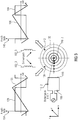
- Fig. 3 1 shows a schematic view of the conductor loop arrangement 110, a cross section of the current-carrying second conductor region 110_2 of the conductor loop arrangement 110 together with field lines 108 of the magnetic field which is generated by the current-carrying conductor region 110_2 of the conductor loop arrangement 110, and in a first diagram 134 a profile of a first Position 136 of the receiver coil assembly 102 is applied to the z-coil 116_3 induced voltage 138 over time and in a second diagram 140 a plot of a voltage 144 induced at a second position 142 of the receiver coil assembly 102 into the z-coil 116_3 is plotted over time. Furthermore, in the first diagram 134 and the second diagram 140, a profile of the current 106 through the second conductor region 110_2 of the conductor loop arrangement 110 is shown.
- an unbalanced signal (AC signal) 106 such as a triangular signal, is used.
- AC signal an unbalanced signal
- One possible evaluation method in a circuit is the time measurement between rising and falling edges of the in Fig. 3 shown voltage waveforms 138 and 144 of the voltages induced in the z-coil 116_3.
- the measuring device 100 can thus additionally evaluate the amplitude of the magnetic field component signal (received signal) 112.
- this position information can be determined without knowing the previous position of the receiver coil arrangement (sensor coil) 102 solely on the basis of the induced voltage.
- the corresponding signals are in Fig. 3 shown.
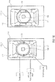
- Fig. 4a shows a schematic view of the conductor loop assembly (bottom coil) 110 and the z-coil 116_3 of the receiver coil assembly 102.
- the conductor loop surface 113 of the conductor loop arrangement 110 and the coil surface 119 of the z-coil 116_3 are aligned parallel to one another.
- the conductor loop surface 113 of the conductor loop arrangement 110 lies in a plane which is spanned by the conductor loop arrangement 110 and which is bounded by the conductor loop arrangement 110.
- the coil surface 119 of the z-coil 116_3 lies in a plane which is spanned by the z-coil 116_3 and is limited by the z-coil 116_3.
- the conductor loop assembly 110 and the z-coil 116_3 are arranged along directions that are parallel to the z-axis.
- Fig. 4b 12 shows a schematic view of the conductor loop arrangement 110, the x-coil 116_1 of the receiver coil arrangement 102, cross sections of the first and second current-carrying conductor region 110_1 of the conductor loop arrangement as well as field lines 108 of the magnetic field which is caused by the current flow through the first conductor region 110_1 and the second conductor region 110_2 ,
- Fig. 4b shows on the left side the new vertical orientation (x, y orientation) and on the right an enlargement.
- page assignment There is the possibility of page assignment by the phase jump of the magnetic field component signals of the x-coil 116_1 and the y-coil 116_2.
- the x-coil 116_1 of the receiver coil assembly 102 is moved along a direction of movement 120 that is antiparallel to the x-axis.
- the phase jump when passing the conductor loop arrangement (transmitting coil) 110 occurs when the receiving coil (eg x-coil 116_1) the influence of one side (eg right of the geometric center or center of gravity of the conductor coil assembly or bottom coil 110)
- Conductor loop arrangement (transmitting coil) 110 leaves and enters the sphere of influence of the other side (eg left of the geometric center or center of gravity of the conductor loop arrangement or bottom coil 110).
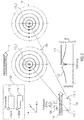
- Fig. 5a shows a schematic view of three x-coarse areas 152_x0 to 152_x2 a positioning surface 151, which can determine the measuring device 100 based on the magnetic field component signal of the x-coil 116_1.
- the positioning surface 151 (bounded by the ring 150 in FIG Fig. 5a ), which may be associated with the conductor loop assembly 110, may be parallel to a conductor loop plane spanned by the conductor loop assembly 110.
- the positioning surface can be equal to or greater than the conductor loop surface 113, which lies in the conductor loop plane and is limited by the conductor loop arrangement 110.
- the evaluation device 104 may be configured to evaluate the magnetic field component signal of the x-coil 116_1 to determine a phase relationship between the magnetic field component signal of the x-coil 116_1 and the electrical AC signal to determine.
- the phase relationship may include coarse position information of the x-coil 116_1 relative to the conductor loop arrangement 110, as will be explained below.
- phase relationship between the magnetic field component signal of the x-coil 116_1 and the ac electrical signal 106 will have a phase jump if the x-coil 116_1 is the geometric center the conductor loop assembly 110 crosses.
- the phase relationship prior to the occurrence of the phase jump, the phase relationship has a first phase, whereas after the occurrence of the phase jump, the phase relationship has a second phase.
- phase relationship between the magnetic field component signal of the x-coil 116_1 and the alternating electrical signal 106 can thus assume three different states depending on the position of the x-coil 116_1 relative to the conductor loop arrangement 110, namely a phase jump (state 0), a first phase ( State 1), eg - 90 °, and a second phase (state 2), e.g. + 90 °.
- the phase relationship thus has coarse-position information which, as a function of the current phase relationship between the magnetic field component signal of the x-coil 116_1 and the alternating electrical signal 106, indicates one of three possible x-coarse ranges 152_x1 to 152_x3, the three possible x-coarse ranges 152_x1 to 152_x3 do not overlap or overlap.
- FIG. 5b a schematic view of three y-coarse areas 152_y0 to 152_y2 of the positioning surface 151, which can determine the measuring device 100 based on the magnetic field component signal of the y-coil 116_2, while Fig. 5c shows a schematic view of three z-coarse regions 152_z0 to 152_z2 of the positioning surface 151, which can determine the measuring device 100 based on the magnetic field component signal of the z-coil 116_3.
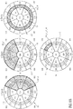
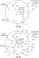
- Fig. 6a Fig. 12 is a schematic view showing coarse areas indicated by the coarse position information of the phase relationships of the magnetic field component signals of the x coil 116_1, y coil 116_2 and z coil 116_3, and a fine range resulting from the intersection of the indicated coarse areas.
- the phase relationship between the magnetic field component signal of the x coil 116_1 and the AC electric signal 106 has a phase jump (state 0), so that the first rough position information indicates the first x coarse region 152_x0.
- the phase relationship between the magnetic field component signal of the y-coil 116_2 and the ac electrical signal 106 has a second phase (state 2), so that the second coarse position information indicates the third y-coarse region 152_y2.
- the phase relationship between the magnetic field component signal of the z-coil 116_3 and the AC electrical signal 106 has a first phase (state 1), so that the third coarse position information indicates the second z-coarse region 152_z1.
- the indicated coarse areas 152_x0, 152_y2 and 152_z1 overlap in the fine area 154_x0_y2_z1.
- the fine region 154_x0_y2_z1 indicates the position of the receiver coil assembly 102 relative to the conductor loop assembly 110.
- Fig. 6b Fig. 12 is a schematic view showing coarse areas indicated by the coarse position information of the phase relationships of the magnetic field component signals of the x coil 116_1, y coil 116_2 and z coil 116_3, and a fine range resulting from the intersection of the indicated coarse areas.
- the phase relationship between the magnetic field component signal of the x coil 116_1 and the AC electric signal 106 has a first phase (state 1), so that the first coarse position information indicates the second x coarse region 152_x1.
- the phase relationship between the magnetic field component signal of the y-coil 116_2 and the ac electrical signal 106 has a first phase (state 1), so that the second coarse position information indicates the second y-coarse region 152_y1.
- the phase relationship between the magnetic field component signal of the z-coil 116_3 and the ac electrical signal 106 has a phase jump (state 0), so that the third coarse position information indicates the first z-coarse region 152_z0.
- the indicated coarse areas 152_x1, 152_y1 and 152_z1 overlap in the fine area 154_x1_y1_z0.
- the fine region 154_x1_y1_z0 indicates the position of the receiver coil assembly 102 relative to the conductor loop assembly 110.
- Fig. 6c Fig. 12 is a schematic view showing coarse areas indicated by the coarse position information of the phase relationships of the magnetic field component signals of the x coil 116_1, y coil 116_2 and z coil 116_3, and a fine range resulting from the intersection of the indicated coarse areas.
- the phase relationship between the magnetic field component signal of the x coil 116_1 and the AC electric signal 106 has a second phase (state 2), so that the first coarse position information (or x coarse position information) indicates the third x coarse region 152_x2.
- the phase relationship between the magnetic field component signal of 116_2 and the AC electrical signal 106 has a phase jump (state 0) such that the second coarse position information (or y coarse position information) indicates the first y coarse region 152_y0.
- phase relationship between the magnetic field component signal of the z-coil 116_3 and the ac electrical signal 106 has a second phase (state 2) such that the third coarse position information (or z-coarse position information) indicates the third z-coarse region 152_z2.
- the indicated coarse areas 152_x2, 152_y0 and 152_z2 overlap in the fine area 154_x2_y0_z2.
- the fine region 154_x2_y0_z2 indicates the position of the receiver coil assembly 102 relative to the conductor loop assembly 110.
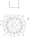
- Fig. 7 shows a schematic view of the conductor loop assembly 110 and the positioning surface 151, which is bounded by the circle 150 and the conductor loop assembly 110 is assigned.
- Fig. 7 In an example with a circular conductor loop arrangement (bottom coil) 110, the individual fields or sectors are shown.
- the in Fig. 7 shown 26 possible fine areas. Theoretically, 27 different fine ranges are possible, but the state 002 does not occur in the real structure.
- each of the fine areas can be described by a three-digit state.
- the first digit of the three-digit state indicates the coarse position information of the x-coil 116_1, while the second digit of the three-digit state indicates the rough position information of 116_2, and while the third digit of the three-digit state indicates the coarse position information of the z-coil 116_3.
- Each digit of the three-digit state can assume the values 0, 1 or 2.
- the possible states are summarized in the following table: conditions x-coil y coil z coil 0 undefined undefined undefined 1 right above Inside 2 Left below Outside
- Fig. 7 thus shows the distinguishable states when a 3D sensor coil 102 is moved over the conductor loop assembly (bottom coil) 110.
- the state 0 or undefined designates the position at which the direction information which can be determined from the asymmetrical transmission signal cancel and therefore lead to an undefined state, which as such can also be recognized and evaluated. This is particularly true because at this point, although no decision based on the magnetic field component signal can be made, but the magnetic field component signal can be detected per se. If all three coils of the 3D sensor coil 102 show this state, this means that this sensor coil 102 is outside the signal range of the conductor loop arrangement (bottom coil) 110, which is shown in FIG Fig. 7 is characterized by the state 000.
- receiver coil assemblies 102 are additionally integrated into the receiver side of a coil system in which the mutual coverage is to be maximized, and sends on the other side of the corresponding signal, this principle can be applied several times.
- Fig. 8a shows a schematic view of a conductor strip assembly 110 and a measuring device 100 with three receiver coil assemblies 102_1 to 102_3.
- the evaluation of the magnetic field component signals of the two further receiver coil arrangements 102_2 and 102_3 by the evaluation device takes place analogously to the evaluation of the receiver coil arrangement 102_1.
- the fine areas 154 of the positioning surface may be associated with directional information indicative of the geometric center of the conductor loop assembly 110, wherein the evaluator 104 may be configured to determine, based on the directional information associated with the fine range, the intersection of the indicated gross ranges results in outputting a direction signal indicative of an estimated direction to the geometric center of gravity of the conductor loop assembly 110.
- the evaluation device 102 can thus determine a first direction information 180_1 based on the magnetic field component signals of the first receiver coil arrangement 102_1, a second direction information 180_2 based on the magnetic field component signals of the second receiver coil arrangement 102_2 and a third direction information 180_3 based on the magnetic field component signals of the third receiver coil arrangement 102_3.
- These three directional information 180_1, 180_2, and 180_3 may be combined to obtain resultant direction information 182, as shown in FIG Fig. 8a is shown.
- the resulting direction information 182 can point from a current position 184 of the measuring device to the geometric center 186 of the conductor loop arrangement 110.
- the current position 184 may be a geometric center of gravity of a (receiver) conductor loop arrangement 111 of a vehicle, wherein the three receiver coil arrangements 102_1 to 102_3 of the measuring device 100 at equal intervals (equidistant) to the geometric center of the (receiver) 184 Conductor loop assembly 111 may be arranged.
- Fig. 8a Example relative target positions 187_1 to 187_3 the receiver coil assemblies 102_1 to 102_3 located.
- Current positions of the receiver coil arrangements 102_1 to 102_3 coincide with the relative target positions 187_1 to 187_3 if the current position 184 of the measuring apparatus, eg the geometric center or center of gravity of the (receiver) conductor loop arrangement 111, with the geometric center or shear point 186 of the conductor loop assembly 110 matches.
- Fig. 8b shows a schematic view of a conductor loop assembly 110 and a measuring device 100 with six receiver coil assemblies 102_1 to 102_6.
- the evaluation device 102 may have a first direction information 180_1 based on the magnetic field component signals of the first receiver coil arrangement 102_1, a second direction information 180_2 based on the magnetic field component signals of the second receiver coil arrangement 102_2, third direction information 180_3 based on the magnetic field component signals of the third receiver coil arrangement 102_3, fourth direction information 180_4 based on determine the magnetic field component signals of the fourth receiver coil assembly 102_4, fifth direction information 180_5 based on the magnetic field component signals of the fifth receiver coil assembly 102_5, and sixth direction information 180_6 based on the magnetic field component signals of the sixth receiver coil assembly 102_6.
- the resulting direction information 182 can point from a current position 184 of the measuring device to the geometric center 186 of the conductor loop arrangement 110.
- the current position 184 may be a geometric center of gravity of a (receiver) conductor loop arrangement 111 of a vehicle, the three receiver coil arrangements 102_1 to 102_6 of the measuring device 100 being equidistant from the geometric center 184 of the (receiver).
- Conductor loop assembly 111 may be arranged.
- Fig. 8b by way of example, relative target positions 187_1 to 187_6 of the receiver coil arrangements 102_1 to 102_6 are shown.
- Current positions of the receiver coil assemblies 102_1 to 102_6 coincide with the relative target positions 187_1 to 187_6 when the current position 184 of the measuring device, eg, the geometric center of the (receiver) conductor loop assembly 111, coincides with the geometric center or shear point 186 of the conductor loop arrangement 110 matches.
- Fig. 8a shows a large conductor loop assembly (bottom coil) 110 and three receiver coil assemblies (sensor coils) 102_1 to 102_3.
- the conductor loop arrangement 110 sends out a position signal.
- Each of the receiver coil assemblies (sensor coils) 102_1 to 102_3 may provide a single vector 180_1 to 180_3 due to phase measurements relative to the target position (geometric center 186 of the conductor loop assembly 110).
- the resulting vector 182 yields a directional indication of the correct position 186.
- the following describes how the accuracy of this result, which is based only on the phase measurement, can be improved.
- the field vector 182 can be determined more accurately. As the number of sensor coils increases, so does the accuracy of the resulting position correction vector, as shown in FIG Fig. 8b is shown.
- This evaluation only relates to a signal evaluation (amplitude / phase) with 3D sensor coils independent of the signal form of the transmission signal. By combining this method with the above-described asymmetric signal, the accuracy of the positioning can be further increased.
- the described system is also reversible, so that the movable system part transmits the positioning signal.
- FIG. 12 shows a flowchart of a measurement method 200 according to an exemplary embodiment of the present invention.
- the measuring method 200 includes a step 202 of detecting three magnetic field components of a magnetic field generated by an AC electric signal of a conductor loop arrangement, wherein the magnetic field components are detected along linearly independent directions; a step 204 of providing a magnetic field component signal for each of the detected three magnetic field components; and a step 206 of evaluating the magnetic field component signals to determine phase relationships associated with the magnetic field component signals to the AC electrical signal, the phase relationships each having coarse position information of the receiver coil assembly relative to the transmitter coil assembly, wherein the evaluating comprises determining a resulting intersection of the coarse position information; Intersection has a fine position information of the receiver coil assembly relative to the Porterschleifenanssen employs.
- Fig. 10 shows a schematic block diagram of a data transfer device 190 according to an embodiment of the present invention.
- the data transmission device has a data transmission and / or data reception device 192, a receiver coil arrangement 102, an evaluation device 104 and a control device 194.
- the receiver coil arrangement 102 is designed to detect at least one magnetic field component of a magnetic field 108 generated by an electrical alternating current signal 106 of a conductor loop arrangement 110 of another data transmission device 198 and to provide a magnetic field component signal 112 for the detected magnetic field component 108.
- the evaluation device 104 is configured to evaluate the magnetic field component signal 112 to determine a phase relationship between the magnetic field component signal 112 and the AC electrical signal 106, the phase relationships having position information indicating whether projection of the receiver coil assembly 102 is perpendicular to a conductor loop surface within the conductor loop surface wherein the conductor loop surface lies in a plane which is spanned by the conductor loop arrangement 110, and wherein the conductor loop surface is limited by the conductor loop arrangement 110.
- the control device 194 is designed to enable data transmission of the data transmission and / or data reception device 192 only if the projection of the receiver coil arrangement 102 lies perpendicular to the conductor loop surface inside or outside the conductor loop surface.
- the receiver coil assembly 102 may be configured to detect a magnetic field component of the magnetic field of the conductor loop assembly that is orthogonal to the conductor loop surface 113.
- the receiver coil arrangement 102 can have, for example, the z-coil 116_3.
- the receiver coil assembly 102 may also include the x-coil 116_1 and / or the y-coil 116_2, wherein the evaluation device 104 may be configured to provide the Further, the position of receiver coil assembly 102 relative to conductor loop assembly 110 may be determined based on the magnetic field component signals of x-coil 116_1 and y-coil 116_2.
- the data transmission device 190 may comprise the measuring device 100 described above, wherein the control device 194 may be configured to release the data transmission of the data transmission and / or data reception device 192 based on the fine position determined by the evaluation device 104.
- the receiver coil 116_3 may be geometrically smaller than the transmitter coil 110 of the system or the signal evaluation as in principle Fig. 3 shown to be applicable.
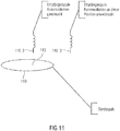
- the step of determining the position may take place, for example, before the actual communication transmission. This is precisely in adjacent transmission stations misallocation of the communication partners, eg due to overreach prevented, see. Fig. 11 ,
- Fig. 12 shows a flowchart of a method for data transmission between a data transmission device and another data transmission device.
- the method comprises a step 222 of detecting a magnetic field component of a magnetic field generated by an AC electrical signal of a conductor loop arrangement; a step 224 of providing a magnetic field component signal for the detected magnetic field component; a step 226 of evaluating the magnetic field component signal to determine a phase relationship between the magnetic field component signal and the AC electrical signal, wherein the phase relationships include position information indicating whether a projection of the receiver coil assembly is perpendicular to a conductor loop surface within the conductor loop surface, the conductor loop surface in one Plane which is spanned by the conductor loop arrangement, and wherein the conductor loop surface is limited by the conductor loop arrangement; and a step 228 of enabling the data transfer between the data transfer device and the further data transfer device if the projection of the receiver coil assembly is perpendicular to the conductor loop surface inside or outside the conductor loop surface.
- aspects have been described in the context of a device, it will be understood that these aspects also constitute a description of the corresponding method, so that a block or a component of a device is also to be understood as a corresponding method step or as a feature of a method step. Similarly, aspects described in connection with or as a method step also represent a description of a corresponding block or detail or feature of a corresponding device.
- Some or all of the method steps may be performed by a hardware device (or using a hardware device). Apparatus), such as a microprocessor, a programmable computer or an electronic circuit. In some embodiments, some or more of the most important method steps may be performed by such an apparatus.
- embodiments of the invention may be implemented in hardware or in software.
- the implementation may be performed using a digital storage medium, such as a floppy disk, a DVD, a Blu-ray Disc, a CD, a ROM, a PROM, an EPROM, an EEPROM or FLASH memory, a hard disk, or other magnetic disk or optical memory are stored on the electronically readable control signals that can cooperate with a programmable computer system or cooperate such that the respective method is performed. Therefore, the digital storage medium can be computer readable.
- some embodiments according to the invention include a data carrier having electronically readable control signals capable of interacting with a programmable computer system such that one of the methods described herein is performed.
- embodiments of the present invention may be implemented as a computer program product having a program code, wherein the program code is operable to perform one of the methods when the computer program product runs on a computer.
- the program code can also be stored, for example, on a machine-readable carrier.
- an embodiment of the method according to the invention is thus a computer program which has a program code for performing one of the methods described herein when the computer program runs on a computer.
- a further embodiment of the inventive method is thus a data carrier (or a digital storage medium or a computer-readable medium) on which the computer program is recorded for carrying out one of the methods described herein.
- a further embodiment of the method according to the invention is thus a data stream or a sequence of signals, which represent the computer program for performing one of the methods described herein.
- the data stream or the sequence of signals may be configured, for example, to be transferred via a data communication connection, for example via the Internet.
- Another embodiment includes a processing device, such as a computer or a programmable logic device, that is configured or adapted to perform one of the methods described herein.
- a processing device such as a computer or a programmable logic device, that is configured or adapted to perform one of the methods described herein.
- Another embodiment includes a computer on which the computer program is installed to perform one of the methods described herein.
- Another embodiment according to the invention comprises a device or system adapted to transmit a computer program for performing at least one of the methods described herein to a receiver.
- the transmission can be done for example electronically or optically.
- the receiver may be, for example, a computer, a mobile device, a storage device or a similar device.
- the device or system may include a file server for transmitting the computer program to the recipient.
- a programmable logic device eg, a field programmable gate array, an FPGA
- a field programmable gate array may cooperate with a microprocessor to perform one of the methods described herein.
- the methods are performed by any hardware device. This may be a universal hardware such as a computer processor (CPU) or hardware specific to the process, such as an ASIC.
Description
Ausführungsbeispiele der vorliegenden Erfindung beziehen sich auf eine Messvorrichtung, ein Positionierungssystem und ein Messverfahren. Weitere Ausführungsbeispiele beziehen sich auf eine Datenübertragungsvorrichtung, ein Datenübertragungssystem und ein Verfahren zur Datenübertragung bei vorgegebener Position. Manche Ausführungsbeispiele beziehen sich auf eine Spulenüberdeckung.Embodiments of the present invention relate to a measuring device, a positioning system and a measuring method. Further embodiments relate to a data transmission device, a data transmission system and a method for data transmission at a predetermined position. Some embodiments relate to a coil overlap.
Systeme zur drahtlosen Energieübertragung mittels Spulen (magnetisches Feld) sind in ihrer Effizienz stark von der korrekten Ausrichtung und damit genügenden Verkoppelung von Sende- und Empfangsspule abhängig. Schon kleine Abweichungen von der idealen Position haben große Auswirkung auf die erreichbare Signalstärke am Empfänger und den Systemwirkungsgrad.Systems for wireless energy transmission by means of coils (magnetic field) are highly dependent on the correct alignment and thus sufficient coupling of transmitting and receiving coil in their efficiency. Even small deviations from the ideal position have a major impact on the achievable signal strength at the receiver and the system efficiency.
Aktuell gibt es mehrere Ansätze, um die exakte Positionierung zu gewährleisten. Bekannt ist eine mechanische Fixierung der Spule mittels Gehäuseform oder Magneten, wodurch Primär- und Sekundärspule auf die korrekte Position gezwungen werden. Ferner ist eine einseitige Verwendung eines Spulenarrays bekannt, das je nach Position der anderen Übertragungsseite optimal verschaltet wird. Des Weiteren sind bewegliche Spulen auf einer Übertragungsseite bekannt, die durch Messung der Kopplung zwischen beiden Spulen an die optimale Position geführt werden. Darüber hinaus sind besondere Spulengeometrien bekannt, die einen breiteren Feldverlauf und somit eine positionstolerantere Positionierung ermöglichen.Currently, there are several approaches to ensure the exact positioning. A mechanical fixation of the coil by means of housing form or magnets is known, whereby the primary and secondary coils are forced to the correct position. Furthermore, a one-sided use of a coil array is known, which is optimally connected depending on the position of the other transmission side. Furthermore, movable coils are known on a transmission side, which are guided by measuring the coupling between the two coils to the optimum position. In addition, special coil geometries are known which allow a broader field profile and thus a position-tolerant positioning.
Die
Die oben beschriebenen Ansätze zur Positionierung von Spulen sind jedoch entweder sehr aufwendig zu implementieren oder nicht für die Positionierung von mobilen Spulen geeignet.However, the above-described approaches for positioning coils are either very expensive to implement or not suitable for the positioning of mobile coils.
Der vorliegenden Erfindung liegt somit die Aufgabe zugrunde, ein Konzept zu schaffen, welches ein verbessertes Verhältnis zwischen Implementierungsaufwand und exakter Positionierung mobiler Spulen ermöglicht.The present invention is therefore based on the object to provide a concept which allows an improved relationship between implementation effort and exact positioning of mobile coils.
Diese Aufgabe wird durch die unabhängigen Patentansprüche gelöst. Weiterbildungen befinden sich in den abhängigen Patentansprüchen.This object is solved by the independent claims. Further developments are in the dependent claims.
Ausführungsbeispiele der vorliegenden Erfindung schaffen eine Messvorrichtung mit einer Empfängerspulenanordnung und einer Auswerteeinrichtung. Die Empfängerspulenanordnung ist ausgebildet, um drei Magnetfeldkomponenten eines durch ein elektrisches Wechselstromsignal erzeugten magnetischen Feldes einer Leiterschleifenanordnung zu erfassen und um für jede der erfassten drei Magnetfeldkomponenten ein Magnetfeldkomponentensignal bereitzustellen. Die Auswerteeinrichtung ist ausgebildet, um die Magnetfeldkomponentensignale auszuwerten, um die für die Magnetfeldkomponentensignale zugeordnete Phasenbeziehung zu dem elektrischen Wechselstromsignal zu bestimmen, wobei die Phasenbeziehungen jeweils eine Grobpositionsinformation der Leiterschleifenanordnung relativ zu der Leiterschleifenanordnung aufweisen, und wobei die Auswerteeinrichtung ausgebildet ist, um eine resultierende Schnittmenge der Grobpositionsinformationen zu ermitteln, wobei die resultierende Schnittmenge eine Feinpositionsinformation der Empfängerspulenanordnung relativ zu der Leiterschleifenanordnung aufweist bzw. ergibt.Embodiments of the present invention provide a measuring device with a receiver coil arrangement and an evaluation device. The receiver coil assembly is configured to detect three magnetic field components of a magnetic field generated by an AC electrical signal of a conductor loop assembly and to provide a magnetic field component signal for each of the detected three magnetic field components. The evaluation device is configured to evaluate the magnetic field component signals in order to determine the phase relationship associated with the magnetic field component signals relative to the electrical alternating current signal, the phase relationships each having coarse position information of the conductor loop arrangement relative to the conductor loop arrangement, and wherein the evaluation device is designed to generate a resulting intersection of the Determine coarse position information, wherein the resulting intersection has a fine position information of the receiver coil assembly relative to the conductor loop arrangement or results.
Gemäß dem Konzept der vorliegenden Erfindung kann eine Position einer Empfängerspulenanordnung relativ zu einer Leiterschleifenanordnung, die ein magnetisches Feld aussendet, ermittelt werden, indem entlang linear unabhängiger Richtungen drei Komponenten des magnetische Feldes erfasst werden, um Magnetfeldkomponentensignale zu erhalten, wobei Phasenbeziehung dieser Magnetfeldkomponentensignale zu einem elektrischen Wechselstromsignal, das das magnetische Feld erzeugt, Grobpositionsinformationen der Empfängerspulenanordnung relativ zu der Leiterschleifenanordnung aufweist. Dadurch, dass die Magnetfeldkomponenten entlang linear unabhängiger Richtungen erfasst werden, sind auch die Grobpositionsinformationen, die den Phasenbeziehungen zwischen den Magnetfeldkomponentensignalen und dem elektrischem Wechselstromsignal entnommen werden können, unabhängig, so dass durch Bilden der Schnittmenge der Grobpositionsinformationen eine Feinpositionsinformation der Empfängerspulenanordnung relativ zu der Leiterschleifenanordnung ermittelt werden kann.In accordance with the concept of the present invention, a position of a receiver coil assembly relative to a magnetic field transmitting loop assembly can be determined by detecting along linearly independent directions three components of the magnetic field to obtain magnetic field component signals, wherein phase relationship of these magnetic field component signals to electrical AC signal generating the magnetic field has coarse position information of the receiver coil assembly relative to the conductor loop assembly. By detecting the magnetic field components along linearly independent directions, the coarse position information that can be extracted from the phase relationships between the magnetic field component signals and the AC electric signal is also independent, such that by forming the intersection of the coarse position information, a fine position information of the receiver coil assembly relative to the conductor loop assembly is determined can be.
Bei Ausführungsbeispielen kann die Messvorrichtung beispielsweise verwendet werden, um ein Fahrzeug auf einer Ladevorrichtung zum Laden eines elektrischen Energiespeichers des Fahrzeugs zu positionieren, wobei die Ladevorrichtung die Leiterschleifenanordnung aufweist.In embodiments, the measuring device may be used, for example, to position a vehicle on a charging device for charging an electrical energy storage device of the vehicle, the charging device having the conductor loop arrangement.
Weitere Ausführungsbeispiele schaffen ein Messverfahren. Das Messverfahren umfasst einen Schritt des Erfassens von drei Magnetfeldkomponenten eines durch ein elektrisches Wechselstromsignal erzeugten magnetischen Feldes einer Leiterschleifenanordnung, wobei die Magnetfeldkomponenten entlang linear unabhängiger Richtungen erfasst werden; einen Schritt des Bereitstellens eines Magnetfeldkomponentensignals für jede der erfassten drei Magnetfeldkomponenten; und einen Schritt des Auswertens der Magnetfeldkomponentensignale, um für die Magnetfeldkomponentensignale zugeordnete Phasenbeziehungen zu dem elektrischen Wechselstromsignal zu bestimmen, wobei die Phasenbeziehungen jeweils eine Grobpositionsinformation der Empfängerspulenanordnung relativ zu der Senderingspulenanordnung aufweisen, wobei das Auswerten Ermitteln einer resultierenden Schnittmenge der Grobpositionsinformationen aufweist, wobei die resultierende Schnittmenge eine Feinpositionsinformation der Empfängerspulenanordnung relativ zu der Leiterschleifenanordnung aufweist/ergibt.Further embodiments provide a measuring method. The measuring method comprises a step of detecting three magnetic field components of a magnetic field generated by an AC electric signal of a conductor loop arrangement, the magnetic field components being detected along linearly independent directions; a step of providing a magnetic field component signal for each of the detected three magnetic field components; and a step of evaluating the magnetic field component signals to determine phase relationships to the AC electrical signal associated with the magnetic field component signals, the phase relationships each having coarse position information of the receiver coil assembly relative to the transmitter coil assembly, wherein the evaluating comprises determining a resulting intersection of the coarse position information, the resulting intersection has fine position information of the receiver coil assembly relative to the conductor loop assembly.
Weitere Ausführungsbeispiele schaffen eine Datenübertragungsvorrichtung mit einer Datensende- und/oder Datenempfangseinrichtung, einer Empfängerspulenanordnung, einer Auswerteeinrichtung und einer Steuervorrichtung. Die Empfängerspulenanordnung ist ausgebildet, um zumindest eine Magnetfeldkomponente eines durch ein elektrisches Wechselstromsignal erzeugten magnetischen Feldes einer Leiterschleifenanordnung einer weiteren Datenübertragungsvorrichtung zu erfassen und um für die erfasste Magnetfeldkomponente ein Magnetfeldkomponentensignal bereitzustellen. Die Auswerteeinrichtung ist ausgebildet, um das Magnetfeldkomponentensignal auszuwerten, um eine Phasenbeziehung zwischen dem Magnetfeldkomponentensignal und dem elektrischen Wechselstromsignal zu bestimmen, wobei die Phasenbeziehung eine Positionsinformation aufweist, die angibt, ob eine Projektion der Empfängerspulenanordnung senkrecht zu einer Leiterschleifenfläche innerhalb der Leiterschleifenfläche liegt, wobei die Leiterschleifenfläche in einer Ebene liegt, die durch die Leiterschleifenanordnung aufgespannt wird, und wobei die Leiterschleifenfläche durch die Leiterschleifenanordnung begrenzt wird. Die Steuervorrichtung ist ausgebildet, um eine Datenübertragung der Datensende- und/oder Datenempfangseinrichtung nur dann freizugeben, wenn die Projektion der Empfängerspulenanordnung senkrecht zur Leiterschleifenfläche innerhalb oder außerhalb der Leiterschleifenfläche liegt.Further embodiments provide a data transmission device with a data transmission and / or data reception device, a receiver coil arrangement, an evaluation device and a control device. The receiver coil arrangement is designed to detect at least one magnetic field component of a magnetic field generated by an electrical alternating current signal of a conductor loop arrangement of a further data transmission device and to provide a magnetic field component signal for the detected magnetic field component. The evaluator is configured to evaluate the magnetic field component signal to determine a phase relationship between the magnetic field component signal and the AC electrical signal, wherein the phase relationship includes position information indicating whether a projection of the receiver coil assembly is perpendicular to a conductor loop surface within the conductor loop surface, the conductor loop surface lies in a plane which is spanned by the conductor loop arrangement, and wherein the conductor loop surface is limited by the conductor loop arrangement. The control device is designed to enable a data transmission of the data transmission and / or data reception device only if the projection of the receiver coil arrangement is perpendicular to the conductor loop surface inside or outside the conductor loop surface.
Weitere Ausführungsbeispiele schaffen ein Verfahren zur Datenübertragung zwischen einer Datenübertragungsvorrichtung und einer weiteren Datenübertragungsvorrichtung. Das Verfahren umfasst Erfassen einer Magnetfeldkomponente eines durch ein elektrisches Wechselstromsignal erzeugten magnetischen Feldes einer Leiterschleifenanordnung; Bereitstellen eines Magnetfeldkomponentensignals für die erfasste Magnetfeldkomponente; Auswerten des Magnetfeldkomponentensignals, um eine Phasenbeziehung zwischen dem Magnetfeldkomponentensignal und dem elektrischen Wechselstromsignal zu bestimmen, wobei die Phasenbeziehungen eine Positionsinformation aufweisen, die angibt, ob eine Projektion der Empfängerspulenanordnung senkrecht zu einer Leiterschleifenfläche innerhalb der Leiterschleifenfläche liegt, wobei die Leiterschleifenfläche in einer Ebene liegt, die durch die Leiterschleifenanordnung aufgespannt wird, und wobei die Leiterschleifenfläche durch die Leiterschleifenanordnung begrenzt wird; und Freigeben der Datenübertragung zwischen der Datenübertragungsvorrichtung und der weiteren Datenübertragungsvorrichtung, sofern die Projektion der Empfängerspulenanordnung senkrecht zu der Leiterschleifenfläche innerhalb oder außerhalb der Leiterschleifenfläche liegt.Further embodiments provide a method for data transmission between a data transmission device and another data transmission device. The method includes detecting a magnetic field component of an electric field AC signal generated magnetic field of a conductor loop arrangement; Providing a magnetic field component signal for the detected magnetic field component; Evaluating the magnetic field component signal to determine a phase relationship between the magnetic field component signal and the AC electrical signal, wherein the phase relationships include position information indicating whether a projection of the receiver coil assembly is perpendicular to a conductor loop surface within the conductor loop surface, the conductor loop surface lying in a plane is clamped by the conductor loop arrangement, and wherein the conductor loop surface is limited by the conductor loop arrangement; and enabling data transfer between the data transfer device and the other data transfer device if the projection of the receiver coil assembly is perpendicular to the loop surface within or outside the loop surface.
Ausführungsbeispiele der vorliegenden Erfindung werden Bezug nehmend auf die beiliegenden Zeichnungen näher erläutert. Es zeigen:
- Fig. 1a
- ein schematisches Blockschaltbild einer Messvorrichtung gemäß einem Ausführungsbeispiel der vorliegenden Erfindung;
- Fig. 1b
- eine schematische Ansicht eines Fahrzeugs bei korrekter Positionierung und nicht korrekter Positionierung auf einer Ladevorrichtung mit einer Leiterschleifenanordnung zum Laden des Fahrzeugs;
- Fig. 2
- eine schematische Ansicht einer Leiterschleifenanordnung und einer Empfängerspulenanordnung mit einer z-Spule sowie in einem Diagramm einen Verlauf des Magnetfeldkomponentensignals der z-Spule, wenn die Empfängerspulenanordnung mit der z-Spule entlang der in
Fig. 2 gezeigten Bewegungsrichtung einen ersten Leiterbereich der Leiterschleifenanordnung überquert; - Fig. 3
- eine schematische Ansicht der Leiterschleifenanordnung, eines Querschnitts des stromdurchflossenen zweiten Leiterbereichs der Leiterschleifenanordnung zusammen mit Feldlinien des magnetischen Feldes, das durch ein unsymmetrisches Wechselstromsignal erzeugt wird, sowie in einem ersten Diagramm einen Verlauf einer an einer ersten Position der Empfängerspulenanordnung in die zSpule induzierte Spannung aufgetragen über die Zeit und in einem zweiten Diagramm einen Verlauf einer an einer zweiten Position der Empfängerspulenanordnung in die z-Spule induzierte Spannung aufgetragen über die Zeit;
- Fig. 4a
- eine schematische Ansicht der Leiterschleifenanordnung und der z-Spule der Empfängerspulenanordnung;
- Fig. 4b
- eine schematische Ansicht der Leiterschleifenanordnung, der x-Spule der Empfängerspulenanordnung, Querschnitte des ersten und zweiten stromdurchflossenen Leiterbereichs der Leiterschleifenanordnung sowie Feldlinien des magnetischen Feldes, das durch den Stromfluss durch den ersten Leiterbereich und den zweiten Leiterbereich hervorgerufen wird;
- Fig. 5a
- eine schematischen Ansicht von drei x-Grobbereichen einer Positionierungsfläche, die die Messeinrichtung basierend auf dem Magnetfeldkomponentensignal der x-Spule ermitteln kann;
- Fig. 5b
- eine schematischen Ansicht von drei y-Grobbereichen einer Positionierungsfläche, die die Messeinrichtung basierend auf dem Magnetfeldkomponentensignal der y-Spule ermitteln kann;
- Fig. 5c
- eine schematischen Ansicht von drei z-Grobbereichen einer Positionierungsfläche, die die Messeinrichtung basierend auf dem Magnetfeldkomponentensignal der z-Spule ermitteln kann;
- Fig. 6a
- in einer schematischen Ansicht Grobbereiche, die von den Grobpositionsinformationen der Phasenbeziehungen der Magnetfeldkomponentensignale der x-Spule, y-Spule und z-Spule angezeigt werden, sowie ein Feinbereich, der aus der Schnittmenge der angezeigten Grobbereiche resultiert;
- Fig. 6b
- in einer schematischen Ansicht Grobbereiche, die von den Grobpositionsinformationen der Phasenbeziehungen der Magnetfeldkomponentensignale der x-Spule, y-Spule und z-Spule angezeigt werden, sowie ein Feinbereich, der aus der Schnittmenge der angezeigten Grobbereiche resultiert;
- Fig. 6c
- in einer schematischen Ansicht Grobbereiche, die von den Grobpositionsinformationen der Phasenbeziehungen der Magnetfeldkomponentensignale der x-Spule, y-Spule und z-Spule angezeigt werden, sowie ein Feinbereich, der aus der Schnittmenge der angezeigten Grobbereiche resultiert;
- Fig. 7
- eine schematische Ansicht der Leiterschleifenanordnung sowie der Positionierungsfläche, die durch einen Kreis begrenzt wird und der Leiterschleifenanordnung zugeordnet ist;
- Fig. 8a
- eine schematische Ansicht einer Leiterstreifenanordnung und einer Messvorrichtung mit drei Empfängerspulenanordnungen;
- Fig. 8b
- eine schematische Ansicht einer Leiterstreifenanordnung und einer Messvorrichtung mit drei Empfängerspulenanordnungen;
- Fig. 9
- ein Flussdiagramm eines Messverfahrens gemäß einem Ausführungsbeispiel der vorliegenden Erfindung;
- Fig. 10
- ein schematisches Blockschaltbild einer Datenübertragungsvorrichtung gemäß einem Ausführungsbeispiel der vorliegenden Erfindung;
- Fig. 11
- ein schematisches Blockschaltbild einer Leiterschleifenanordnung sowie einer korrekt positionierten z-Spule und einer nicht korrekt positionierten z-Spule; und
- Fig. 12
- ein Flussdiagramm eines Verfahrens zur Datenübertragung zwischen einer Datenübertragungsvorrichtung und einer weiteren Datenübertragungsvorrichtung.
- Fig. 1a
- a schematic block diagram of a measuring device according to an embodiment of the present invention;
- Fig. 1b
- a schematic view of a vehicle with correct positioning and incorrect positioning on a loading device with a conductor loop arrangement for loading the vehicle;
- Fig. 2
- a schematic view of a conductor loop arrangement and a receiver coil arrangement with a z-coil and a diagram of a course of the magnetic field component signal of the z-coil when the receiver coil assembly with the z-coil along the in
Fig. 2 shown movement direction crosses a first conductor region of the conductor loop arrangement; - Fig. 3
- a schematic view of the conductor loop arrangement, a cross section of the current-carrying second conductor region of the conductor loop arrangement together with field lines of the magnetic field, which is generated by an asymmetrical AC signal, and in a first diagram, a curve of a voltage induced at a first position of the receiver coil assembly in the z-coil voltage over the time and in a second diagram a plot of a voltage induced in the z-coil at a second position of the receiver coil assembly plotted over time;
- Fig. 4a
- a schematic view of the conductor loop assembly and the z-coil of the receiver coil assembly;
- Fig. 4b
- a schematic view of the conductor loop arrangement, the x-coil of the receiver coil assembly, cross sections of the first and second current-carrying conductor region of the conductor loop arrangement and field lines of the magnetic field, which is caused by the current flow through the first conductor region and the second conductor region;
- Fig. 5a
- a schematic view of three x-coarse regions of a positioning surface, which can determine the measuring device based on the magnetic field component signal of the x-coil;
- Fig. 5b
- a schematic view of three y-coarse regions of a positioning surface, which can determine the measuring device based on the magnetic field component signal of the y-coil;
- Fig. 5c
- a schematic view of three z-coarse regions of a positioning surface, which can determine the measuring device based on the magnetic field component signal of the z-coil;
- Fig. 6a
- in a schematic view, coarse areas indicated by the coarse position information of the phase relationships of the magnetic field component signals of the x coil, y coil, and z coil and a fine range resulting from the intersection of the indicated coarse areas;
- Fig. 6b
- in a schematic view, coarse areas indicated by the coarse position information of the phase relationships of the magnetic field component signals of the x coil, y coil, and z coil and a fine range resulting from the intersection of the indicated coarse areas;
- Fig. 6c
- in a schematic view of coarse areas, which are the coarse position information of the phase relationships of the magnetic field component signals of the x-coil, y coil and z coil, as well as a fine range resulting from the intersection of the indicated coarse ranges;
- Fig. 7
- a schematic view of the conductor loop assembly and the positioning surface, which is bounded by a circle and associated with the conductor loop assembly;
- Fig. 8a
- a schematic view of a conductor strip assembly and a measuring device with three receiver coil assemblies;
- Fig. 8b
- a schematic view of a conductor strip assembly and a measuring device with three receiver coil assemblies;
- Fig. 9
- a flowchart of a measuring method according to an embodiment of the present invention;
- Fig. 10
- a schematic block diagram of a data transmission device according to an embodiment of the present invention;
- Fig. 11
- a schematic block diagram of a conductor loop arrangement and a correctly positioned z-coil and a not correctly positioned z-coil; and
- Fig. 12
- a flowchart of a method for data transmission between a data transmission device and another data transmission device.
In der nachfolgenden Beschreibung von Ausführungsbeispielen der vorliegenden Erfindung werden gleiche oder gleichwirkende Elemente mit den gleichen Bezugszeichen versehen, so dass deren Beschreibung untereinander austauschbar ist.In the following description of exemplary embodiments of the present invention, identical or equivalent elements are given the same reference numerals, so that their description is interchangeable.
Die Empfängerspulenanordnung 102 ist ausgebildet, um drei Magnetfeldkomponenten eines durch ein elektrisches Wechselstromsignal 106 erzeugten magnetischen Feldes 108 einer Leiterschleifenanordnung 110 zu erfassen und um für jede der erfassten drei Magnetfeldkomponenten ein Magnetfeldkomponentensignal 112 bereitzustellen.The
Die Auswerteeinrichtung 104 ist ausgebildet, um die Magnetfeldkomponentensignale 112 auszuwerten, um für die Magnetfeldkomponentensignale 112 zugeordnete Phasenbeziehungen zu dem elektrischen Wechselstromsignal 106 zu bestimmen, wobei die Phasenbeziehungen jeweils eine Grobpositionsinformation der Empfängerspulenanordnung 102 relativ zu der Leiterschleifenanordnung 110 aufweisen, und wobei die Auswerteeinrichtung 104 ausgebildet ist, um eine resultierende Schnittmenge der Grobpositionsinformationen zu ermitteln, wobei die resultierende Schnittmenge eine Feinpositionsinformation der Empfängerspulenanordnung 102 relativ zu der Leiterschleifenanordnung 110 aufweist bzw. ergibt.The
Die Empfängerspulenanordnung 102 ist dabei ausgebildet, um die drei Magnetfeldkomponenten entlang linear unabhängiger Richtungen zu erfassen.
Bei Ausführungsbeispielen kann die Empfängerspulenanordnung 102 drei Spulen 116_1 bis 116_3 aufweisen, die relativ zueinander angeordnet sind, um die drei Magnetfeldkomponenten des erzeugten magnetischen Feldes 108 der Leiterschleifenanordnung 110 zu erfassen.In embodiments, the
Jede der drei Spulen 116_1 bis 116_3 kann dabei eines der drei Magnetfeldkomponentensignale 112 bereitstellen. Beispielsweise kann eine erste Spule 116_1 der drei Spulen 116_1 bis 116_3 ein erstes Magnetfeldkomponentensignal der drei Magnetfeldkomponentensignale bereitstellen, während eine zweite Spule 116_2 der drei Spulen 116_1 bis 116_3 ein zweites Magnetfeldkomponentensignal der drei Magnetfeldkomponentensignale bereitstellen kann, und während eine dritte Spule 116_3 der drei Spulen 116_1 bis 116_3 ein drittes Magnetfeldkomponentensignal der drei Magnetfeldkomponentensignale bereitstellen kann.Each of the three coils 116_1 to 116_3 can thereby provide one of the three magnetic field component signals 112. For example, a first coil 116_1 of the three coils 116_1 to 116_3 may provide a first magnetic field component signal of the three magnetic field component signals, while a second coil 116_2 of the three coils 116_1 to 116_3 may provide a second magnetic field component signal of the three magnetic field component signals, and while a third coil 116_3 of the three coils 116_1 to 116_3 can provide a third magnetic field component signal of the three magnetic field component signals.
Bei Ausführungsbeispielen kann die Empfängerspulenanordnung 102 ausgebildet sein, um die die drei Magnetfeldkomponenten entlang orthogonaler Richtungen zu erfassen. Beispielsweise kann in diesem Fall das in
In der nachfolgenden Beschreibung wird vereinfacht davon ausgegangen, dass die Empfängerspulenanordnung 102 ausgebildet ist, um drei Magnetfeldkomponenten entlang orthogonaler Richtung, d.h. parallel zu x-y-z-Achsen des kartesischen Koordinatensystems zu erfassen. Es sei jedoch darauf hingewiesen, dass die Erfindung nicht auf solche Ausführungsbespiele beschränkt ist. Vielmehr kann die Empfängerspulenanordnung 102 ausgebildet sein, um Magnetfeldkomponenten des magnetischen Feldes 108 der Leiterschleifenanordnung 110 entlang linear unabhängiger Richtungen zu erfassen.In the following description, it is simplified to assume that the
Ferner sei darauf hingewiesen, dass, obwohl in
Bei der Übertragung von Daten und oder Energie mittels verkoppelter Spulen (Leiterschleifenanordnungen) ist die exakte Positionierung der an der Übertragung beteiligten Spulen zueinander entscheidend für eine effiziente und fehlerfreie Übertragung. Durch eine spezielle Signalform, die von einer Spule bzw. (Sende)Leiterschleifenanordnung 110 ausgesendet wird und von einer weiteren Spule bzw. (Empfangs) Leiterschleifenanordnung empfangen wird, kann anhand der empfangenen Signale die Orientierung der beiden Spulen zueinander ermittelt werden und auch der Versatz der Spulen zueinander festgestellt werden. Mit diesen Informationen kann die Ausrichtung der Spulen zueinander korrigiert und so die Übertragung optimiert werden. Zudem kann bei einem Kommunikationssystem die Lage der beteiligten Spulen zueinander überprüft werden.In the transmission of data and / or energy by means of coupled coils (conductor loop arrangements), the exact positioning of the coils involved in the transmission is crucial for an efficient and error-free transmission. By means of a special signal form which is emitted by a coil or (transmitting)
Die Messvorrichtung 100 ermöglicht es somit bei Daten- und/oder Energieübertragungssystemen mit Spulen (Leiterschleifenanordnungen; Sendeleiterschleifenanordnung und Empfangsleiterschleifenanordnung), Informationen über die Orientierung und Lage der beteiligten Spulen zueinander zu gewinnen. Mit diesen Informationen ist eine Optimierung der Anordnung bei Fehlpositionierung möglich um höhere Übertragungseffizienz zu erreichen. Dadurch ist es auch möglich sicherzustellen, dass die beteiligten Spulen wie gewünscht zueinander positioniert sind. Dies ist vor allem dann interessant wenn sich mehrere Systeme in unmittelbarer Nachbarschaft befinden und es sonst, z.B. aufgrund von Überreichweiten zu falschen Zuordnungen von Kommunikationspartnern kommen kann.Thus, in data and / or energy transmission systems with coils (conductor loop arrangements, transmit conductor loop arrangement and receive conductor loop arrangement), the
Das in
Ausführungsbeispiele lösen die Aufgabe die Position einer mobilen Leiterschleifenanordnung bzw. mobilen Spule (z.B. Ladespule in einem Elektroauto) 111 als Teil eines induktiv gekoppelten Ladesystems in Bezug zur stationären Primärspule 110 zu orten und daraus Steuerinformationen für die Bewegung der mobilen Spule 111 (Fahrzeug) abzuleiten, um die mobile Spule 111 in die für das Laden und/oder Kommunizieren optimale Position zu manövrieren.
Ausführungsbeispiele ermöglichen es festzustellen, wo sich eine Empfängerspule in Bezug auf die Sendespule 110 befindet. Wenn mehrere Empfängerspulen vorhanden sind, so kann aus einer bekannten Lage dieser Empfängerspulen zueinander und den von ihnen empfangenen Signalen die Orientierung des Empfängersystems zu einer Sendespule 110 bestimmt werden. Mit den gewonnenen Signalen kann so die Positionierung des Übertragungssystems zueinander optimiert werden. Da die ermittelten Werte sich unmittelbar in Positionsangaben umsetzen lassen ist diese Methode exakter als eine Positionskontrolle auf Grundlage von Signalstärkemessungen da zusätzliche Information zu Lage ermittelt werden.Embodiments make it possible to determine where a receiver coil is with respect to the
Die Lösung setzt sich aus zwei Teilaspekten zusammen. Einmal aus dem Auswerten des Phasensprungs in der z-Komponente einer Sensorspule der Empfängerspulenanordnung beim Überqueren einer Sendespule (Bodenspule) 110 in Kombination mit unsymmetrischen Sendesignalen 106 zur eindeutigen Unterscheidung zwischen Innen und Außen der Sendespule 110. Dieses Prinzip wird durch die Verwendung einer 3D Empfangsspule 102 erweitert. Zum anderen kann durch das Auswerten der Empfangsfeldstärken bei einer 3D Empfangsspule 102 ein Richtungsvektor zur Feldquelle (Bodenspule 110) ermittelt werden. Werden mehrere Vektoren solcher 3D Empfangsspulen 102 kombiniert so lassen sich daraus Positionierungsangaben generieren.The solution consists of two aspects. Once from the evaluation of the phase jump in the z-component of a sensor coil of the receiver coil assembly when crossing a transmitting coil (bottom coil) 110 in combination with unbalanced transmission signals 106 for clear distinction between inside and outside of the transmitting
Im Folgenden wird die Funktionsweise der in
Wird durch eine Leiterschleifenanordnung 110 (z.B. eine Sendespule oder erste Spule) ein elektrisches Wechselsignal, z.B. ein sinusförmiges oder dreieckförmiges Stromsignal 106, geleitet, so entsteht im Nahfeld um diese Leiterschleifenanordnung 110 ein magnetisches Wechselfeld 108, das mit einer Empfängerleitschleifenanordnung (z.B. eine Empfängerspule oder zweiten Spule) 111 empfangen werden kann. Die aktuelle Position kann durch die Analyse des empfangenen Signals (Magnetfeldkomponentensignal) ermittelt werden, da sich beim Überfahren oder Überqueren der Leiterschleifenanordnung 110 (Sendespule) die Phase des empfangenen Signals einen Sprung aufweist, d.h. sich um 180° dreht, wie dies in
Aus dem Diagramm in
Wenn die Empfängerspulenanordnung 102 weiter entlang der Bewegungsrichtung 120 bewegt wird, weist das Magnetfeldkomponentensignal der z-Spule 116_3 einen weiteren Phasensprung auf, wenn die z-Spule 116_3 den zweiten Leiterbereich 110_2 der Leiterschleifenanordnung 110 überquert.As the
Wie in
Weiterhin ist es möglich, Signale über einen Schnitt-Trigger zu führen und anschließend durch eine Integration des induzierten Spulensignals (Magnetfeldkomponentensignals) und einem Vergleich mit einem Mittelwert des empfangenen Signals eine eindeutige Zuordnung des Spulensignals zu einer Leiterseite zu treffen, da sich aufgrund des Phasensprungs auf der einen Seite des Leiterbereichs 110_2 (z.B. erste Position 136) ein kleinerer Integrationswert als auf der anderen Seite des Leiterbereichs 110_2 (z.B. zweite Position 142) ergibt.Furthermore, it is possible to carry signals via a cut trigger and then by an integration of the induced coil signal (magnetic field component signal) and a comparison with an average value of the received signal to make a clear assignment of the coil signal to a conductor side, as due to the phase jump on the one side of the conductor region 110_2 (eg first position 136) yields a smaller integration value than on the other side of the conductor region 110_2 (eg second position 142).
Die Messvorrichtung 100 kann somit zusätzlich die Amplitude des Magnetfeldkomponentensignals (Empfangssignals) 112 auswerten. Bei einer unsymmetrischen Signalform des durch die Leiterschleifenanordnung 110 (Bodenspule) laufenden Stroms 106 kann diese Positionsinformation ohne Kenntnis der vorherigen Position der Empfängerspulenanordnung (Sensorspule) 102 allein anhand der induzierten Spannung ermittelt werden. Die entsprechenden Signale sind in
Im Gegensatz zu Ausführungsbeispielen der vorliegenden Erfindung, lassen sich mit dem aus der
Bei Ausführungsbeispielen wird hingegen die Kombination der im Folgenden beschriebenen technische Effekte genutzt.In embodiments, however, the combination of the technical effects described below is used.
Aus
Wenn die Empfängerspulenfläche hingegen orthogonal zu der Leiterschleifenfläche (Sendespulenfläche) angeordnet ist, wie dies beispielsweise bei der x-Spule 116_1 der Fall ist und in
Kombiniert man nun diese beiden Überlegungen und fügt noch eine dritte Spule (z.B. y-Spule 116_2) hinzu, die senkrecht zu den anderen beiden steht (3D-Spule), ergibt sich eine Anordnung, die in x-, y- und z-Richtung jeweils drei Zustände erkennt, was z.B. bei einer kreisförmigen Leiterschleifenanordnung (Bodenspule) 110 eine Unterteilung in theoretisch 27, praktisch 26 verschiedene Bereiche zulässt, wie im Folgenden erläutert wird.Combining these two considerations and adding a third coil (eg y-coil 116_2), which is perpendicular to the other two (3D coil), results in an arrangement in the x-, y- and z-direction each three states recognizes what eg in a circular conductor loop arrangement (ground coil) 110 allows a division into theoretically 27, practically 26 different areas, as will be explained below.
Die Positionierungsfläche 151 (begrenzt durch den Ring 150 in
Bei Ausführungsbeispielen kann die Auswerteeinrichtung 104 ausgebildet sein, um das Magnetfeldkomponentensignal der x-Spule 116_1 auszuwerten, um eine Phasenbeziehung zwischen dem Magnetfeldkomponentensignal der x-Spule 116_1 und dem elektrischen Wechselstromsignal zu bestimmen. Die Phasenbeziehung kann dabei eine Grobpositionsinformation der x-Spule 116_1 relativ zu der Leiterschleifenanordnung 110 aufweisen, wie im Folgenden erläutert wird.In embodiments, the
Wenn die x-Spule 116_1 die Leiterschleifenanordnung 110 in x-Richtung vollständig überquert, dann weist die Phasenbeziehung zwischen dem Magnetfeldkomponentensignal der x-Spule 116_1 und dem elektrischen Wechselstromsignal 106 einen Phasensprung dann auf, wenn die x-Spule 116_1 den geometrischen Mittelpunkt bzw. Schwerpunkt der Leiterschleifenanordnung 110 überquert. Vor dem Auftreten des Phasensprungs weist die Phasenbeziehung also eine erste Phase auf, wohingegen nach dem Auftreten des Phasensprungs die Phasenbeziehung eine zweite Phase aufweist.When the x-coil 116_1 completely traverses the
Die Phasenbeziehung zwischen dem Magnetfeldkomponentensignal der x-Spule 116_1 und dem elektrischen Wechselstromsignal 106 kann demnach in Abhängigkeit von der Position der x-Spule 116_1 relativ zu der Leiterschleifenanordnung 110 drei verschiedene Zustände einnehmen, und zwar einen Phasensprung (Zustand 0), eine erste Phase (Zustand 1), z.B. - 90°, und eine zweite Phase (Zustand 2), z.B. +90°. Die Phasenbeziehung weist somit eine Grobpositionsinformation auf, die in Abhängigkeit von der aktuellen Phasenbeziehung zwischen dem Magnetfeldkomponentensignal der x-Spule 116_1 und dem elektrischen Wechselstromsignal 106 einen von drei möglichen x-Grobbereichen 152_x1 bis 152_x3 anzeigt, wobei sich die drei möglichen x-Grobbereiche 152_x1 bis 152_x3 nicht überlappen bzw. überschneiden.The phase relationship between the magnetic field component signal of the x-coil 116_1 and the alternating
Analog hierzu zeigt
In
Die angezeigten Grobbereiche 152_x0, 152_y2 und 152_z1 überlappen sich in dem Feinbereich 154_x0_y2_z1. Der Feinbereich 154_x0_y2_z1 zeigt die Position der Empfängerspulenanordnung 102 relativ zu der Leiterschleifenanordnung 110 an.The indicated coarse areas 152_x0, 152_y2 and 152_z1 overlap in the fine area 154_x0_y2_z1. The fine region 154_x0_y2_z1 indicates the position of the
In
Die angezeigten Grobbereiche 152_x1, 152_y1 und 152_z1 überlappen sich in dem Feinbereich 154_x1_y1_z0. Der Feinbereich 154_x1_y1_z0 zeigt die Position der Empfängerspulenanordnung 102 relativ zu der Leiterschleifenanordnung 110 an.The indicated coarse areas 152_x1, 152_y1 and 152_z1 overlap in the fine area 154_x1_y1_z0. The fine region 154_x1_y1_z0 indicates the position of the
In
Die angezeigten Grobbereiche 152_x2, 152_y0 und 152_z2 überlappen sich in dem Feinbereich 154_x2_y0_z2. Der Feinbereich 154_x2_y0_z2 zeigt die Position der Empfängerspulenanordnung 102 relativ zu der Leiterschleifenanordnung 110 an.The indicated coarse areas 152_x2, 152_y0 and 152_z2 overlap in the fine area 154_x2_y0_z2. The fine region 154_x2_y0_z2 indicates the position of the
Wie in
Werden mehrere solcher Empfängerspulenanordnungen 102 zusätzlich in die Empfängerseite eines Spulensystems integriert, bei denen die gegenseitige Abdeckung maximiert werden soll, und sendet auf der anderen Seite das entsprechende Signal, so kann dieses Prinzip mehrmals angewendet werden.If several such
Zusätzlich kann durch Feldstärkemessungen an 3D-Sensorspulen 110 mit einer gewissen Genauigkeit (abhängig von Anzahl und Position der Sensorspulen) auf die aktuelle Positionierung der Systemspulen 110 und 111 zueinander geschlossen werden und entsprechende Korrekturdaten für die Positionierung des Übertragungssystems gewonnen werden. Dem System aus
Bei Ausführungsbeispielen können den Feinbereichen 154 der Positionierungsfläche Richtungsinformationen zugeordnet sein, die auf den geometrischen Schwerpunkt bzw. Mittelpunkt der Leiterschleifenanordnung 110 hindeuten, wobei die Auswerteeinrichtung 104 ausgebildet sein kann, um basierend auf der Richtungsinformation, die dem Feinbereich zugeordnet ist, der durch die Schnittmenge der angezeigten Grobbereiche resultiert, ein Richtungssignal auszugeben, das eine geschätzte Richtung zu dem geometrischen Schwerpunkt der Leiterschleifenanordnung 110 hindeutet bzw. zeigt.In embodiments, the fine areas 154 of the positioning surface may be associated with directional information indicative of the geometric center of the
Bezogen auf
Ferner sind in
Ferner sind in
Mit anderen Worten,
Erfolgt eine Phasen- und Amplitudenmessung, so kann der Feldvektor 182 genauer bestimmt werden. Wird die Anzahl der Sensorspulen erhöht, so erhöht sich auch die Genauigkeit des resultierenden Vektors zur Positionskorrektur, wie dies in
Das beschriebene System ist auch umkehrbar, so dass der bewegliche Systemteil das Positionierungssignal aussendet.The described system is also reversible, so that the movable system part transmits the positioning signal.
Wie bereits erwähnt ist bei der Übertragung von Daten und oder Energie mittels verkoppelter Spulen (Leiterschleifenanordnungen) die exakte Positionierung der an der Übertragung beteiligten Spulen zueinander entscheidend für eine effiziente und fehlerfreie Übertragung. Im Folgenden wird eine Datenübertragungsvorrichtung beschrieben, bei der die Übertragung von Daten mittels verkoppelter Spulen (Leiterschleifenanordnungen) erfolgt. Die oben beschriebenen Merkmale sind dabei ebenfalls auf die Datenübertragungsvorrichtung anwendbar bzw. übertragbar.As already mentioned, in the transmission of data and / or energy by means of coupled coils (conductor loop arrangements), the exact positioning of the coils involved in the transmission is crucial for an efficient and error-free transmission. The following describes a data transmission device in which the transmission of data takes place by means of coupled coils (conductor loop arrangements). The features described above are also applicable to the data transmission device or transferable.
Bei Ausführungsbeispielen kann die Empfängerspulenanordnung 102 ausgebildet sein, um eine Magnetfeldkomponente des magnetischen Feldes der Leiterschleifenanordnung zu erfassen, die orthogonal zu der Leiterschleifenfläche 113 verläuft. Hierzu kann die Empfängerspulenanordnung 102 beispielsweise die z-Spule 116_3 aufweisen.In embodiments, the
Natürlich kann die Empfängerspulenanordnung 102 auch die x-Spule 116_1 und/oder y-Spule 116_2 aufweisen, wobei die Auswerteinrichtung 104 ausgebildet sein kann, um die Position der Empfängerspulenanordnung 102 relativ zu der Leiterschleifenanordnung 110 ferner basierend auf den Magnetfeldkomponentensignalen der x-Spule 116_1 und y-Spule 116_2 zu ermitteln. Mit anderen Worten, die Datenübertragungsvorrichtung 190 kann die oben beschriebene Messvorrichtung 100 aufweisen, wobei die Steuervorrichtung 194 ausgebildet sein kann, um basierend auf der von der Auswerteinrichtung 104 ermittelten Feinposition die Datenübertragung der Datensende- und/oder Datenempfangseinrichtung 192 freizugeben.Of course, the
Mit der oben beschriebenen Vorrichtung 100 bzw. dem oben beschrieben Verfahren 200 ist es somit auch möglich bei einem induktiven Datenübertragungssystem zu gewährleisten dass eine Übertragung nur stattfinden kann wenn sich die Empfängerspule innerhalb 113 oder sogar an einer bestimmten Position innerhalb 113 der Senderspule 110 befindet. Dazu kann die Empfängerspule 116_3 geometrisch kleiner als die Senderspule 110 des Systems sein bzw. die Signalauswertung wie prinzipiell in
Obwohl manche Aspekte im Zusammenhang mit einer Vorrichtung beschrieben wurden, versteht es sich, dass diese Aspekte auch eine Beschreibung des entsprechenden Verfahrens darstellen, sodass ein Block oder ein Bauelement einer Vorrichtung auch als ein entsprechender Verfahrensschritt oder als ein Merkmal eines Verfahrensschrittes zu verstehen ist. Analog dazu stellen Aspekte, die im Zusammenhang mit einem oder als ein Verfahrensschritt beschrieben wurden, auch eine Beschreibung eines entsprechenden Blocks oder Details oder Merkmals einer entsprechenden Vorrichtung dar. Einige oder alle der Verfahrensschritte können durch einen Hardware-Apparat (oder unter Verwendung eine Hardware-Apparats), wie zum Beispiel einen Mikroprozessor, einen programmierbaren Computer oder eine elektronische Schaltung. Bei einigen Ausführungsbeispielen können einige oder mehrere der wichtigsten Verfahrensschritte durch einen solchen Apparat ausgeführt werden.Although some aspects have been described in the context of a device, it will be understood that these aspects also constitute a description of the corresponding method, so that a block or a component of a device is also to be understood as a corresponding method step or as a feature of a method step. Similarly, aspects described in connection with or as a method step also represent a description of a corresponding block or detail or feature of a corresponding device. Some or all of the method steps may be performed by a hardware device (or using a hardware device). Apparatus), such as a microprocessor, a programmable computer or an electronic circuit. In some embodiments, some or more of the most important method steps may be performed by such an apparatus.
Je nach bestimmten Implementierungsanforderungen können Ausführungsbeispiele der Erfindung in Hardware oder in Software implementiert sein. Die Implementierung kann unter Verwendung eines digitalen Speichermediums, beispielsweise einer Floppy-Disk, einer DVD, einer Blu-ray Disc, einer CD, eines ROM, eines PROM, eines EPROM, eines EEPROM oder eines FLASH-Speichers, einer Festplatte oder eines anderen magnetischen oder optischen Speichers durchgeführt werden, auf dem elektronisch lesbare Steuersignale gespeichert sind, die mit einem programmierbaren Computersystem derart zusammenwirken können oder zusammenwirken, dass das jeweilige Verfahren durchgeführt wird. Deshalb kann das digitale Speichermedium computerlesbar sein.Depending on particular implementation requirements, embodiments of the invention may be implemented in hardware or in software. The implementation may be performed using a digital storage medium, such as a floppy disk, a DVD, a Blu-ray Disc, a CD, a ROM, a PROM, an EPROM, an EEPROM or FLASH memory, a hard disk, or other magnetic disk or optical memory are stored on the electronically readable control signals that can cooperate with a programmable computer system or cooperate such that the respective method is performed. Therefore, the digital storage medium can be computer readable.
Manche Ausführungsbeispiele gemäß der Erfindung umfassen also einen Datenträger, der elektronisch lesbare Steuersignale aufweist, die in der Lage sind, mit einem programmierbaren Computersystem derart zusammenzuwirken, dass eines der hierin beschriebenen Verfahren durchgeführt wird.Thus, some embodiments according to the invention include a data carrier having electronically readable control signals capable of interacting with a programmable computer system such that one of the methods described herein is performed.
Allgemein können Ausführungsbeispiele der vorliegenden Erfindung als Computerprogrammprodukt mit einem Programmcode implementiert sein, wobei der Programmcode dahin gehend wirksam ist, eines der Verfahren durchzuführen, wenn das Computerprogrammprodukt auf einem Computer abläuft.In general, embodiments of the present invention may be implemented as a computer program product having a program code, wherein the program code is operable to perform one of the methods when the computer program product runs on a computer.
Der Programmcode kann beispielsweise auch auf einem maschinenlesbaren Träger gespeichert sein.The program code can also be stored, for example, on a machine-readable carrier.
Andere Ausführungsbeispiele umfassen das Computerprogramm zum Durchführen eines der hierin beschriebenen Verfahren, wobei das Computerprogramm auf einem maschinenlesbaren Träger gespeichert ist. Mit anderen Worten ist ein Ausführungsbeispiel des erfindungsgemäßen Verfahrens somit ein Computerprogramm, das einen Programmcode zum Durchführen eines der hierin beschriebenen Verfahren aufweist, wenn das Computerprogramm auf einem Computer abläuft.Other embodiments include the computer program for performing any of the methods described herein, wherein the computer program is stored on a machine-readable medium. In other words, an embodiment of the method according to the invention is thus a computer program which has a program code for performing one of the methods described herein when the computer program runs on a computer.
Ein weiteres Ausführungsbeispiel der erfindungsgemäßen Verfahren ist somit ein Datenträger (oder ein digitales Speichermedium oder ein computerlesbares Medium), auf dem das Computerprogramm zum Durchführen eines der hierin beschriebenen Verfahren aufgezeichnet ist.A further embodiment of the inventive method is thus a data carrier (or a digital storage medium or a computer-readable medium) on which the computer program is recorded for carrying out one of the methods described herein.
Ein weiteres Ausführungsbeispiel des erfindungsgemäßen Verfahrens ist somit ein Datenstrom oder eine Sequenz von Signalen, der bzw. die das Computerprogramm zum Durchführen eines der hierin beschriebenen Verfahren darstellt bzw. darstellen. Der Datenstrom oder die Sequenz von Signalen kann bzw. können beispielsweise dahin gehend konfiguriert sein, über eine Datenkommunikationsverbindung, beispielsweise über das Internet, transferiert zu werden.A further embodiment of the method according to the invention is thus a data stream or a sequence of signals, which represent the computer program for performing one of the methods described herein. The data stream or the sequence of signals may be configured, for example, to be transferred via a data communication connection, for example via the Internet.
Ein weiteres Ausführungsbeispiel umfasst eine Verarbeitungseinrichtung, beispielsweise einen Computer oder ein programmierbares Logikbauelement, die dahin gehend konfiguriert oder angepasst ist, eines der hierin beschriebenen Verfahren durchzuführen.Another embodiment includes a processing device, such as a computer or a programmable logic device, that is configured or adapted to perform one of the methods described herein.
Ein weiteres Ausführungsbeispiel umfasst einen Computer, auf dem das Computerprogramm zum Durchführen eines der hierin beschriebenen Verfahren installiert ist.Another embodiment includes a computer on which the computer program is installed to perform one of the methods described herein.
Ein weiteres Ausführungsbeispiel gemäß der Erfindung umfasst eine Vorrichtung oder ein System, die bzw. das ausgelegt ist, um ein Computerprogramm zur Durchführung zumindest eines der hierin beschriebenen Verfahren zu einem Empfänger zu übertragen. Die Übertragung kann beispielsweise elektronisch oder optisch erfolgen. Der Empfänger kann beispielsweise ein Computer, ein Mobilgerät, ein Speichergerät oder eine ähnliche Vorrichtung sein. Die Vorrichtung oder das System kann beispielsweise einen Datei-Server zur Übertragung des Computerprogramms zu dem Empfänger umfassen.Another embodiment according to the invention comprises a device or system adapted to transmit a computer program for performing at least one of the methods described herein to a receiver. The transmission can be done for example electronically or optically. The receiver may be, for example, a computer, a mobile device, a storage device or a similar device. For example, the device or system may include a file server for transmitting the computer program to the recipient.
Bei manchen Ausführungsbeispielen kann ein programmierbares Logikbauelement (beispielsweise ein feldprogrammierbares Gatterarray, ein FPGA) dazu verwendet werden, manche oder alle Funktionalitäten der hierin beschriebenen Verfahren durchzuführen. Bei manchen Ausführungsbeispielen kann ein feldprogrammierbares Gatterarray mit einem Mikroprozessor zusammenwirken, um eines der hierin beschriebenen Verfahren durchzuführen. Allgemein werden die Verfahren bei einigen Ausführungsbeispielen seitens einer beliebigen Hardwarevorrichtung durchgeführt. Diese kann eine universell einsetzbare Hardware wie ein Computerprozessor (CPU) sein oder für das Verfahren spezifische Hardware, wie beispielsweise ein ASIC.In some embodiments, a programmable logic device (eg, a field programmable gate array, an FPGA) may be used to to perform some or all of the functionalities of the methods described herein. In some embodiments, a field programmable gate array may cooperate with a microprocessor to perform one of the methods described herein. In general, in some embodiments, the methods are performed by any hardware device. This may be a universal hardware such as a computer processor (CPU) or hardware specific to the process, such as an ASIC.
Die oben beschriebenen Ausführungsbeispiele stellen lediglich eine Veranschaulichung der Prinzipien der vorliegenden Erfindung dar. Es versteht sich, dass Modifikationen und Variationen der hierin beschriebenen Anordnungen und Einzelheiten anderen Fachleuten einleuchten werden. Deshalb ist beabsichtigt, dass die Erfindung lediglich durch den Schutzumfang der nachstehenden Patentansprüche und nicht durch die spezifischen Einzelheiten, die anhand der Beschreibung und der Erläuterung der Ausführungsbeispiele hierin präsentiert wurden, beschränkt sei.The embodiments described above are merely illustrative of the principles of the present invention. It will be understood that modifications and variations of the arrangements and details described herein will be apparent to others of ordinary skill in the art. Therefore, it is intended that the invention be limited only by the scope of the appended claims and not by the specific details presented in the description and explanation of the embodiments herein.
Claims (18)
- Measuring device (100), comprising:a receiver coil array (102) configured to detect three magnetic field components of a magnetic field (108), generated by an electric alternating current signal (106), of a conductor loop array (110) and to provide a magnetic field component signal (112) for each of the detected three magnetic field components, wherein the receiver coil array (102) is configured to detect the three magnetic field components along linearly independent directions; andevaluation means (104) that is configured to evaluate the magnetic field component signals (112) for determining, for the magnetic field component signals (112), allocated phase relations to the electric alternating current signal (106), wherein the phase relations each comprise coarse position information (152) of the receiver coil array 102 relative to the conductor loop array (110), and wherein the evaluation means (104) is configured to determine a resulting intersection of the coarse position information, wherein the resulting intersection comprises fine position information of the receiver coil array (102) relative to the conductor loop array (110);wherein a positioning area (151) is allocated to the conductor loop array (110), wherein the positioning area (151) runs parallel to a conductor loop plane that is spanned by the conductor loop array (110) and wherein the positioning area (151) is of the same size or greater than a conductor loop area (113) that is within the conductor loop plane and is limited by the conductor loop array (110);wherein the coarse position information each indicates a coarse region of several possible coarse regions (152_x0:152_x2:152_y0:152_y2; 152_z0:152_y2) of the positioning area (151), wherein the coarse regions (152_x0:152_x2:152_y0:152_y2; 152_z0:152_y2) indicated by the coarse position information overlap; andwherein the fine position information indicates a fine region of several possible fine regions (154_x0_y0_z0:154_x2_y2_z2) of the positioning area (151) resulting from the intersection of the indicated coarse regions (152_x0:152_2:152_y0:152_y2; 152_z0:152_y2).
- Measuring device (100) according to claim 1, wherein the evaluation means (104) is configured to output a position signal based on the fine region (54_x0_y0_z0:154_x2_y2_z2) resulting from the intersection of the indicated coarse regions (152_x0:152_x2:152_y0:152_y2; 152_z0:152_y2), indicating a position of the receiver coil array (102) relative to the conductor loop array (110).
- Measuring device (100) according to claim 1 or 2, wherein directional information (180_1:180_6) pointing to the geometric centroid (186) of the conductor loop array is allocated to the fine regions (154_x0_y0_z0:154_x2_y2_z2) of the positioning area (151), wherein the evaluation means (104) is configured to output a directional signal (133) indicating an estimated direction to the geometric centroid (186_1:186:6) of the conductor loop array (110) based on the directional information (180_1:180_6) allocated to the fine region (154_x0_y0_z0:154_x2_y2_z2) resulting from the intersection of the indicated coarse regions (152_x0:152_x2:152_y0:152_y2; 152_z0:152_y2).
- Measuring device (100) according to one of claims 1 to 3, wherein the phase relations that are allocated to the magnetic field component signals (112) are respectively one of a first phase, a second phase or a phase jump, wherein the coarse position information comprised by the phase relations indicates in the phase jump a first coarse region (152_x0:152_y0:152_z0) of the possible coarse regions (152_x0:152_x2:152_y0:152_y2; 152_z0:152_y2), wherein the coarse position information indicates in the first phase a second coarse region (152_x2:152_y2:152_z2) of the possible coarse regions (152_x0:152_x2:152_y0:152_y2; 152_z0:152_y2) and wherein the coarse position information indicates in the second phase a third coarse region (152_x2:152_y2:152_z2) of the possible coarse regions (152_x0:152_x2:152_y0:152_y2; 152_z0:152_y2), wherein the first coarse region (152_x0:152_y0:152_z0), the second coarse region (152_x1:152_y1:152_z1) and the third coarse region (152_x2:152_y2:152_z2) that are indicated by the respective coarse position information do not overlap.
- Measuring device (100) according to one of claims 1 to 4, wherein the magnetic field (108) of the conductor loop array (110) is generated by an unbalanced electric alternating current signal (106); and
wherein the evaluation means (104) is configured to evaluate the magnetic field component signals (112) for determining amplitude curves of the magnetic field components (138, 144), wherein the amplitude curves (138, 144) each comprise additional position information of the receiver coil array (102) relative to the conductor loop array (110), and wherein the evaluation means (104) is configured to combine the additional position information and the coarse position information or fine position information. - Measuring device (100) according to one of claims 1 to 5, wherein the phase relation is a phase shift to the electric alternating current signal or a phase jump.
- Measuring device (100) according to one of claims 1 to 6, wherein a first phase-relation allocated to a first magnetic field component signal of the magnetic field component signals (112) comprises a phase jump when crossing a conductor region (110_1, 110_2) of the conductor loop array (110).
- Measuring device (100) according to one of claims 1 to 7, wherein at least a second phase relation allocated to a second magnetic field component signal of the magnetic field component signals (112) comprises a phase jump when crossing a geometric centroid (186) of the conductor loop array (110).
- Measuring device (100) according to one of claims 1 to 8, wherein the three linearly independent directions are orthogonal directions.
- Measuring device (100) according to one of claims 1 to 9, wherein the receiver coil array (102) comprises three coils (116_1:116_3) that are arranged relative to one another to detect the three magnetic field components of the generated magnetic field (108) of the conductor loop array (110).
- Positioning system, comprising:measuring means (100) according to one of claims 1 to 10; anda conductor loop array (110).
- Usage of a measuring device (100) according to one of claims 1 to 11 for positioning a vehicle (114) on a charging device (117) for charging an electric energy storage of the vehicle (114), wherein the charging device comprises the conductor loop array (110).
- Measuring method (200), comprising:detecting (202) three magnetic field components of a magnetic field of a conductor loop array generated by an electric alternating current signal, wherein the magnetic field components are detected along linearly independent directions;providing (204) a magnetic field component signal for each of the detected three magnetic field components; andevaluating (206) the magnetic field component signals for determining, for the magnetic field component signals, allocated phase relations to the electric alternating current signal, wherein the phase relations each comprise coarse position information of the receiver coil array relative to the toroidal transmitter coil array;wherein evaluating (206) comprises determining a resulting intersection of the coarse position information, wherein the resulting intersection comprises/results in fine position information of the receiver coil array relative to the conductor loop array;wherein a positioning area (151) is allocated to the conductor loop array (110), wherein the positioning area (151) runs parallel to a conductor loop plane that is spanned by the conductor loop array (110) and wherein the positioning area (151) is of the same size or greater than a conductor loop area (113) that is within the conductor loop plane and is limited by the conductor loop array (110);wherein the coarse position information each indicates a coarse region of several possible coarse regions (152_x0:152_x2:152_y0:152_y2; 152_z0:152_y2) of the positioning area (151), wherein the coarse regions (152_x0:152_x2:152_y0:152_y2; 152_z0:152_y2) indicated by the coarse position information overlap, andwherein the fine position information indicates a fine region of several possible fine regions (154_x0_y0_z0:154_x2_y2_z2) of the positioning area (151) resulting from the intersection of the indicated coarse regions (152_x0:152_x2:152_y0:152_y2; 152_z0: 152_y2).
- Computer program for performing the method according to claim 13 when the computer program is executed on a computer or microprocessor.
- Data transmission device (190), comprising:a data transceiver (192);a receiver coil array (102) configured to detect three magnetic field components of a magnetic field (108), generated by an electric alternating current signal (106), of a conductor loop array (110) of a further data transmission device (198) and to provide a magnetic field component signal (112) for each of the detected magnetic field components, the receiver coil array (102) being configured to detect the three magnetic field components along linearly independent directions;evaluation means (104) configured to evaluate magnetic field component signals (112) for determining, for the magnetic field component signals (112), associated phase relations to the electric alternating current signal (106), wherein the phase relations each comprise coarse position information (152) of the receiver coil array 102 in relation to the conductor loop array (110), and wherein the evaluation means (104) is configured to determine a resulting intersection of the coarse position information, the resulting intersection comprising fine position information of the receiver coil array (102) in relation to the conductor loop array (110), said fine position information indicating whether a projection of the receiver coil array (102) is perpendicular to a conductor loop area (113) inside the conductor loop area (113), wherein the conductor loop area (113) is within a plane spanned by the conductor loop array (110), and wherein the conductor loop area (113) is limited by the conductor loop array (110); andcontrol means (194) configured to enable data transmission of the data transceiver (192) only when the projection of the receiver coil array (102) is perpendicular to the conductor loop area (113) inside or outside the conductor loop area (113);wherein a positioning area (151) is allocated to the conductor loop array (110), wherein the positioning area (151) runs parallel to a conductor loop plane that is spanned by the conductor loop array (110) and wherein the positioning area (151) is of the same size or greater than a conductor loop area (113) that is within the conductor loop plane and is limited by the conductor loop array (110);wherein the coarse position information each indicates a coarse region of several possible coarse regions (152_x0:152_x2:152_y0:152_y2; 152_z0:152_y2) of the positioning area (151), wherein the coarse regions (152_x0;152_x2:152_y0:152_y2; 152_z0:152_y2) indicated by the coarse position information overlap, andwherein the fine position information indicates a fine region of several possible fine regions (154_x0_y0_z0:154_x2_y2_z2) of the positioning area (151) resulting from the intersection of the indicated coarse regions (152_x0:152_x2:152_y0:152_y2; 152_z0:152_y2).
- Data transmission device (190) according to claim 15, wherein the receiver coil array (102) is configured to detect a magnetic field component of the magnetic field (108) of the conductor loop array (110) running orthogonally to the conductor loop area.
- Data transmission system, comprising:a data transmission device (190) according to claim 17 or 18; anda further data transmission device (198) with the conductor loop array (110).
- Method (220) for data transmission between a data transmission device (190) and a further data transmission device (198) comprising:detecting (222) three magnetic field components of a magnetic field of a conductor loop array generated by an electric alternating current signal, the magnetic field components being detected along linearly independent directions;providing (224) a magnetic field component signal for each of the detected magnetic field components;evaluating (226) magnetic field component signals for determining, for the magnetic field component signals, associated phase relations to the electric alternating current signal, wherein the phase relations each comprise coarse position information of the receiver coil array in relation to the toroidal transmitter coil array, wherein said evaluating (206) comprises determining a resulting intersection of the coarse position information, the resulting intersection comprising/resulting in fine position information of the receiver coil array in relation to the conductor loop array, said fine position information indicating whether a projection of the receiver coil array is perpendicular to a conductor loop area inside the conductor loop area, wherein the conductor loop area is within a plane that is spanned by the conductor loop array and wherein the conductor loop area is limited by the conductor loop array;enabling (228) data transmission between the data transmission device and the further data transmission device if the projection of the receiver coil array perpendicular to the conductor loop area is inside or outside the conductor loop area;wherein a positioning area (151) is allocated to the conductor loop array (110), wherein the positioning area (151) runs parallel to a conductor loop plane that is spanned by the conductor loop array (110) and wherein the positioning area (151) is of the same size or greater than a conductor loop area (113) that is within the conductor loop plane and is limited by the conductor loop array (110);wherein the coarse position information each indicates a coarse region of several possible coarse regions (152_x0:152_x2:152_y0:152_y2; 152_z0:152_y2) of the positioning area (151), wherein the coarse regions (152_x0:152_x2:152_y0;152_y2; 152_z0:152_y2) indicated by the coarse position information overlap, andwherein the fine position information indicates a fine region of several possible fine regions (154_x0_y0_z0:154_x2_y2_z2) of the positioning area (151) resulting from the intersection of the indicated coarse regions (152_x0:152_x2:152_y0:152_y2; 152_z0:152_y2).
Applications Claiming Priority (2)
| Application Number | Priority Date | Filing Date | Title |
|---|---|---|---|
| DE102014215350.6A DE102014215350A1 (en) | 2014-08-04 | 2014-08-04 | COIL OVER COVER |
| PCT/EP2015/067827 WO2016020326A1 (en) | 2014-08-04 | 2015-08-03 | Coil overlap |
Publications (2)
| Publication Number | Publication Date |
|---|---|
| EP3178148A1 EP3178148A1 (en) | 2017-06-14 |
| EP3178148B1 true EP3178148B1 (en) | 2018-09-26 |
Family
ID=53783732
Family Applications (1)
| Application Number | Title | Priority Date | Filing Date |
|---|---|---|---|
| EP15747456.0A Active EP3178148B1 (en) | 2014-08-04 | 2015-08-03 | Coil overlap |
Country Status (6)
| Country | Link |
|---|---|
| US (1) | US10081266B2 (en) |
| EP (1) | EP3178148B1 (en) |
| JP (1) | JP6605582B2 (en) |
| KR (1) | KR101950490B1 (en) |
| DE (1) | DE102014215350A1 (en) |
| WO (1) | WO2016020326A1 (en) |
Families Citing this family (11)
| Publication number | Priority date | Publication date | Assignee | Title |
|---|---|---|---|---|
| US9815342B2 (en) | 2015-11-20 | 2017-11-14 | Ford Global Technologies, Llc | Vehicle positioning to charge TPMS batteries |
| FR3048387B1 (en) | 2016-03-02 | 2019-06-21 | Alstom Transport Technologies | IMPROVED RECHARGE INSTALLATION BY CONDUCTING A VEHICLE |
| US11647678B2 (en) | 2016-08-23 | 2023-05-09 | Analog Devices International Unlimited Company | Compact integrated device packages |
| US10697800B2 (en) * | 2016-11-04 | 2020-06-30 | Analog Devices Global | Multi-dimensional measurement using magnetic sensors and related systems, methods, and integrated circuits |
| DE102017216726A1 (en) | 2017-09-21 | 2019-03-21 | Robert Bosch Gmbh | Method for operating an inductive transmission device |
| FR3073790B1 (en) * | 2017-11-22 | 2019-11-29 | Alstom Transport Technologies | POSITIONING SYSTEM OF AN ELECTRIC VEHICLE IN RELATION TO A CHARGING STATION |
| EP3520695A3 (en) | 2018-01-31 | 2019-11-06 | Analog Devices, Inc. | Electronic devices |
| WO2020002237A1 (en) * | 2018-06-29 | 2020-01-02 | Brusa Elektronik Ag | Vehicle charging system for charging an energy store arranged in a vehicle |
| JP2020167833A (en) * | 2019-03-29 | 2020-10-08 | ローム株式会社 | Wireless power reception device and electronic device |
| EP4012349B1 (en) * | 2020-12-08 | 2023-03-15 | Dr. Johannes Heidenhain GmbH | Scanning element and inductive position measuring device with the same |
| CN114050668B (en) * | 2022-01-07 | 2022-04-15 | 合肥有感科技有限责任公司 | Wireless charging transmitting device |
Family Cites Families (13)
| Publication number | Priority date | Publication date | Assignee | Title |
|---|---|---|---|---|
| GB8625365D0 (en) * | 1986-10-23 | 1986-11-26 | Radiodetection Ltd | Positional information systems |
| US6593884B1 (en) * | 1998-08-02 | 2003-07-15 | Super Dimension Ltd. | Intrabody navigation system for medical applications |
| WO2008146492A1 (en) * | 2007-06-01 | 2008-12-04 | Panasonic Corporation | Communication system, wireless communication terminal device, position estimation device, communication relay device and connecting station |
| DE102007052946B4 (en) | 2007-10-15 | 2016-02-18 | Fraunhofer-Gesellschaft zur Förderung der angewandten Forschung e.V. | Apparatus, method and system for detecting when an object or a person exceeds a boundary marked by a magnetic field |
| US9472097B2 (en) * | 2010-11-15 | 2016-10-18 | Image Sensing Systems, Inc. | Roadway sensing systems |
| US10090885B2 (en) | 2011-04-13 | 2018-10-02 | Qualcomm Incorporated | Antenna alignment and vehicle guidance for wireless charging of electric vehicles |
| KR102490017B1 (en) * | 2011-12-16 | 2023-01-18 | 오클랜드 유니서비시즈 리미티드 | Inductive power transfer system and method |
| DE102012006919A1 (en) * | 2012-04-05 | 2013-10-10 | Sew-Eurodrive Gmbh & Co. Kg | Measuring device for determining relative position of transmitter, connected to charging device of charging plant for electric car, has evaluation unit to automatic determine phase difference between receiving units of receiver |
| DE102012010014B3 (en) * | 2012-05-22 | 2013-09-26 | Sew-Eurodrive Gmbh & Co. Kg | Method for determining the position of a mobile unit and installation for carrying out a method |
| KR20140024741A (en) * | 2012-08-21 | 2014-03-03 | 삼성전기주식회사 | Digitizer |
| US9831705B2 (en) * | 2012-12-12 | 2017-11-28 | Qualcomm Incorporated | Resolving communcations in a wireless power system with co-located transmitters |
| DE102013214238A1 (en) | 2013-07-22 | 2015-01-22 | Zf Friedrichshafen Ag | Drive unit and method for operating the same |
| DE102013214283A1 (en) | 2013-07-22 | 2015-01-22 | Fraunhofer-Gesellschaft zur Förderung der angewandten Forschung e.V. | Apparatus and method for monitoring access to a storage area of a plurality of storage areas for goods |
-
2014
- 2014-08-04 DE DE102014215350.6A patent/DE102014215350A1/en not_active Ceased
-
2015
- 2015-08-03 KR KR1020177006046A patent/KR101950490B1/en active IP Right Grant
- 2015-08-03 JP JP2017506265A patent/JP6605582B2/en not_active Expired - Fee Related
- 2015-08-03 WO PCT/EP2015/067827 patent/WO2016020326A1/en active Application Filing
- 2015-08-03 EP EP15747456.0A patent/EP3178148B1/en active Active
-
2017
- 2017-01-26 US US15/416,413 patent/US10081266B2/en active Active
Non-Patent Citations (1)
| Title |
|---|
| None * |
Also Published As
| Publication number | Publication date |
|---|---|
| KR20170039717A (en) | 2017-04-11 |
| JP2017528703A (en) | 2017-09-28 |
| KR101950490B1 (en) | 2019-02-19 |
| EP3178148A1 (en) | 2017-06-14 |
| WO2016020326A1 (en) | 2016-02-11 |
| JP6605582B2 (en) | 2019-11-13 |
| US20170136906A1 (en) | 2017-05-18 |
| DE102014215350A1 (en) | 2016-02-04 |
| US10081266B2 (en) | 2018-09-25 |
Similar Documents
| Publication | Publication Date | Title |
|---|---|---|
| EP3178148B1 (en) | Coil overlap | |
| EP2782775B1 (en) | System for determining the position of objects which can move with respect to one another | |
| DE102012204634A1 (en) | Magnetic field sensor, actuator and method for determining a relative position | |
| DE102009014801A1 (en) | Inductive proximity switch | |
| WO2013143926A1 (en) | Device for inductive power transmission | |
| DE102014202747A1 (en) | Device for detecting a positional deviation of the passive coil relative to the primary coil of an inductive charging system for a vehicle and associated method | |
| DE102016215212A1 (en) | Movement device with magnetic position determination and data transmission device | |
| EP3008424B1 (en) | Device and method for monitoring access to one storage region of a plurality of storage regions for goods | |
| EP2852818B1 (en) | Method and installation for inductively determining the position of a mobile unit | |
| DE102016217254A1 (en) | Angle of rotation sensor, stator element and rotor element for this | |
| DE102012102855A1 (en) | Method and arrangement for determining the position of a component and sensor | |
| EP1698861B1 (en) | Method and device for determining the respective position of at least one measuring point in a permanent magnetic field | |
| DE102015115447A1 (en) | Measuring method for the determination of iron losses | |
| DE112018000642T5 (en) | Magnetic encoder and method for its production | |
| WO2017137525A1 (en) | Device and method for determining the position of a transmitter in relation to a detection area | |
| DE102019219049A1 (en) | Measuring system for detecting slip in a roller bearing | |
| DE102008012534B4 (en) | Device and method for determining the relative position relative to a transponder or an RFID tag | |
| DE102006044060A1 (en) | Two or multidimensional coil arrangement for wireless energy feeding to e.g. sensor, has two resonance coils attached on central coil body and/or core, where ferrite pieces are fastened on edge regions of coil body and/or core | |
| DE102007018503B4 (en) | Arrangement for determining the position or location of a transponder | |
| WO2019011570A1 (en) | Method for determining a direction of travel and/or position, track-side device, and device for a vehicle | |
| DE102019209324A1 (en) | Method for positioning a vehicle over a floor plate for inductive charging of a vehicle battery | |
| DE102021122249A1 (en) | Measuring device for pantographs and method for operating the measuring device and a calibration device | |
| EP3477245A1 (en) | Method for determining the distance between a first object and a second object | |
| WO2022152865A1 (en) | Device for automatically positioning a charge plug | |
| DE10314737A1 (en) | Equipment determining position of moving transponder in e.g. vehicle, detects and analyses signals from antennas with overlapping characteristic diagrams |
Legal Events
| Date | Code | Title | Description |
|---|---|---|---|
| STAA | Information on the status of an ep patent application or granted ep patent |
Free format text: STATUS: THE INTERNATIONAL PUBLICATION HAS BEEN MADE |
|
| PUAI | Public reference made under article 153(3) epc to a published international application that has entered the european phase |
Free format text: ORIGINAL CODE: 0009012 |
|
| STAA | Information on the status of an ep patent application or granted ep patent |
Free format text: STATUS: REQUEST FOR EXAMINATION WAS MADE |
|
| 17P | Request for examination filed |
Effective date: 20170119 |
|
| AK | Designated contracting states |
Kind code of ref document: A1 Designated state(s): AL AT BE BG CH CY CZ DE DK EE ES FI FR GB GR HR HU IE IS IT LI LT LU LV MC MK MT NL NO PL PT RO RS SE SI SK SM TR |
|
| AX | Request for extension of the european patent |
Extension state: BA ME |
|
| DAV | Request for validation of the european patent (deleted) | ||
| DAX | Request for extension of the european patent (deleted) | ||
| GRAP | Despatch of communication of intention to grant a patent |
Free format text: ORIGINAL CODE: EPIDOSNIGR1 |
|
| STAA | Information on the status of an ep patent application or granted ep patent |
Free format text: STATUS: GRANT OF PATENT IS INTENDED |
|
| INTG | Intention to grant announced |
Effective date: 20180328 |
|
| GRAS | Grant fee paid |
Free format text: ORIGINAL CODE: EPIDOSNIGR3 |
|
| GRAA | (expected) grant |
Free format text: ORIGINAL CODE: 0009210 |
|
| STAA | Information on the status of an ep patent application or granted ep patent |
Free format text: STATUS: THE PATENT HAS BEEN GRANTED |
|
| AK | Designated contracting states |
Kind code of ref document: B1 Designated state(s): AL AT BE BG CH CY CZ DE DK EE ES FI FR GB GR HR HU IE IS IT LI LT LU LV MC MK MT NL NO PL PT RO RS SE SI SK SM TR |
|
| REG | Reference to a national code |
Ref country code: GB Ref legal event code: FG4D Free format text: NOT ENGLISH |
|
| REG | Reference to a national code |
Ref country code: CH Ref legal event code: EP |
|
| REG | Reference to a national code |
Ref country code: AT Ref legal event code: REF Ref document number: 1047173 Country of ref document: AT Kind code of ref document: T Effective date: 20181015 |
|
| REG | Reference to a national code |
Ref country code: IE Ref legal event code: FG4D Free format text: LANGUAGE OF EP DOCUMENT: GERMAN |
|
| REG | Reference to a national code |
Ref country code: DE Ref legal event code: R096 Ref document number: 502015006117 Country of ref document: DE |
|
| REG | Reference to a national code |
Ref country code: NL Ref legal event code: MP Effective date: 20180926 |
|
| PG25 | Lapsed in a contracting state [announced via postgrant information from national office to epo] |
Ref country code: NO Free format text: LAPSE BECAUSE OF FAILURE TO SUBMIT A TRANSLATION OF THE DESCRIPTION OR TO PAY THE FEE WITHIN THE PRESCRIBED TIME-LIMIT Effective date: 20181226 Ref country code: BG Free format text: LAPSE BECAUSE OF FAILURE TO SUBMIT A TRANSLATION OF THE DESCRIPTION OR TO PAY THE FEE WITHIN THE PRESCRIBED TIME-LIMIT Effective date: 20181226 Ref country code: LT Free format text: LAPSE BECAUSE OF FAILURE TO SUBMIT A TRANSLATION OF THE DESCRIPTION OR TO PAY THE FEE WITHIN THE PRESCRIBED TIME-LIMIT Effective date: 20180926 Ref country code: RS Free format text: LAPSE BECAUSE OF FAILURE TO SUBMIT A TRANSLATION OF THE DESCRIPTION OR TO PAY THE FEE WITHIN THE PRESCRIBED TIME-LIMIT Effective date: 20180926 Ref country code: GR Free format text: LAPSE BECAUSE OF FAILURE TO SUBMIT A TRANSLATION OF THE DESCRIPTION OR TO PAY THE FEE WITHIN THE PRESCRIBED TIME-LIMIT Effective date: 20181227 Ref country code: FI Free format text: LAPSE BECAUSE OF FAILURE TO SUBMIT A TRANSLATION OF THE DESCRIPTION OR TO PAY THE FEE WITHIN THE PRESCRIBED TIME-LIMIT Effective date: 20180926 Ref country code: SE Free format text: LAPSE BECAUSE OF FAILURE TO SUBMIT A TRANSLATION OF THE DESCRIPTION OR TO PAY THE FEE WITHIN THE PRESCRIBED TIME-LIMIT Effective date: 20180926 |
|
| REG | Reference to a national code |
Ref country code: LT Ref legal event code: MG4D |
|
| PG25 | Lapsed in a contracting state [announced via postgrant information from national office to epo] |
Ref country code: AL Free format text: LAPSE BECAUSE OF FAILURE TO SUBMIT A TRANSLATION OF THE DESCRIPTION OR TO PAY THE FEE WITHIN THE PRESCRIBED TIME-LIMIT Effective date: 20180926 Ref country code: HR Free format text: LAPSE BECAUSE OF FAILURE TO SUBMIT A TRANSLATION OF THE DESCRIPTION OR TO PAY THE FEE WITHIN THE PRESCRIBED TIME-LIMIT Effective date: 20180926 Ref country code: LV Free format text: LAPSE BECAUSE OF FAILURE TO SUBMIT A TRANSLATION OF THE DESCRIPTION OR TO PAY THE FEE WITHIN THE PRESCRIBED TIME-LIMIT Effective date: 20180926 |
|
| PG25 | Lapsed in a contracting state [announced via postgrant information from national office to epo] |
Ref country code: EE Free format text: LAPSE BECAUSE OF FAILURE TO SUBMIT A TRANSLATION OF THE DESCRIPTION OR TO PAY THE FEE WITHIN THE PRESCRIBED TIME-LIMIT Effective date: 20180926 Ref country code: IS Free format text: LAPSE BECAUSE OF FAILURE TO SUBMIT A TRANSLATION OF THE DESCRIPTION OR TO PAY THE FEE WITHIN THE PRESCRIBED TIME-LIMIT Effective date: 20190126 Ref country code: PL Free format text: LAPSE BECAUSE OF FAILURE TO SUBMIT A TRANSLATION OF THE DESCRIPTION OR TO PAY THE FEE WITHIN THE PRESCRIBED TIME-LIMIT Effective date: 20180926 Ref country code: CZ Free format text: LAPSE BECAUSE OF FAILURE TO SUBMIT A TRANSLATION OF THE DESCRIPTION OR TO PAY THE FEE WITHIN THE PRESCRIBED TIME-LIMIT Effective date: 20180926 Ref country code: ES Free format text: LAPSE BECAUSE OF FAILURE TO SUBMIT A TRANSLATION OF THE DESCRIPTION OR TO PAY THE FEE WITHIN THE PRESCRIBED TIME-LIMIT Effective date: 20180926 Ref country code: RO Free format text: LAPSE BECAUSE OF FAILURE TO SUBMIT A TRANSLATION OF THE DESCRIPTION OR TO PAY THE FEE WITHIN THE PRESCRIBED TIME-LIMIT Effective date: 20180926 Ref country code: NL Free format text: LAPSE BECAUSE OF FAILURE TO SUBMIT A TRANSLATION OF THE DESCRIPTION OR TO PAY THE FEE WITHIN THE PRESCRIBED TIME-LIMIT Effective date: 20180926 |
|
| PG25 | Lapsed in a contracting state [announced via postgrant information from national office to epo] |
Ref country code: PT Free format text: LAPSE BECAUSE OF FAILURE TO SUBMIT A TRANSLATION OF THE DESCRIPTION OR TO PAY THE FEE WITHIN THE PRESCRIBED TIME-LIMIT Effective date: 20190126 Ref country code: SM Free format text: LAPSE BECAUSE OF FAILURE TO SUBMIT A TRANSLATION OF THE DESCRIPTION OR TO PAY THE FEE WITHIN THE PRESCRIBED TIME-LIMIT Effective date: 20180926 Ref country code: SK Free format text: LAPSE BECAUSE OF FAILURE TO SUBMIT A TRANSLATION OF THE DESCRIPTION OR TO PAY THE FEE WITHIN THE PRESCRIBED TIME-LIMIT Effective date: 20180926 |
|
| REG | Reference to a national code |
Ref country code: DE Ref legal event code: R097 Ref document number: 502015006117 Country of ref document: DE |
|
| PG25 | Lapsed in a contracting state [announced via postgrant information from national office to epo] |
Ref country code: DK Free format text: LAPSE BECAUSE OF FAILURE TO SUBMIT A TRANSLATION OF THE DESCRIPTION OR TO PAY THE FEE WITHIN THE PRESCRIBED TIME-LIMIT Effective date: 20180926 |
|
| PLBE | No opposition filed within time limit |
Free format text: ORIGINAL CODE: 0009261 |
|
| STAA | Information on the status of an ep patent application or granted ep patent |
Free format text: STATUS: NO OPPOSITION FILED WITHIN TIME LIMIT |
|
| 26N | No opposition filed |
Effective date: 20190627 |
|
| PG25 | Lapsed in a contracting state [announced via postgrant information from national office to epo] |
Ref country code: SI Free format text: LAPSE BECAUSE OF FAILURE TO SUBMIT A TRANSLATION OF THE DESCRIPTION OR TO PAY THE FEE WITHIN THE PRESCRIBED TIME-LIMIT Effective date: 20180926 |
|
| PG25 | Lapsed in a contracting state [announced via postgrant information from national office to epo] |
Ref country code: TR Free format text: LAPSE BECAUSE OF FAILURE TO SUBMIT A TRANSLATION OF THE DESCRIPTION OR TO PAY THE FEE WITHIN THE PRESCRIBED TIME-LIMIT Effective date: 20180926 |
|
| PG25 | Lapsed in a contracting state [announced via postgrant information from national office to epo] |
Ref country code: MC Free format text: LAPSE BECAUSE OF FAILURE TO SUBMIT A TRANSLATION OF THE DESCRIPTION OR TO PAY THE FEE WITHIN THE PRESCRIBED TIME-LIMIT Effective date: 20180926 Ref country code: LU Free format text: LAPSE BECAUSE OF NON-PAYMENT OF DUE FEES Effective date: 20190803 Ref country code: CH Free format text: LAPSE BECAUSE OF NON-PAYMENT OF DUE FEES Effective date: 20190831 Ref country code: LI Free format text: LAPSE BECAUSE OF NON-PAYMENT OF DUE FEES Effective date: 20190831 |
|
| REG | Reference to a national code |
Ref country code: BE Ref legal event code: MM Effective date: 20190831 |
|
| PG25 | Lapsed in a contracting state [announced via postgrant information from national office to epo] |
Ref country code: IE Free format text: LAPSE BECAUSE OF NON-PAYMENT OF DUE FEES Effective date: 20190803 |
|
| PG25 | Lapsed in a contracting state [announced via postgrant information from national office to epo] |
Ref country code: BE Free format text: LAPSE BECAUSE OF NON-PAYMENT OF DUE FEES Effective date: 20190831 |
|
| PG25 | Lapsed in a contracting state [announced via postgrant information from national office to epo] |
Ref country code: CY Free format text: LAPSE BECAUSE OF FAILURE TO SUBMIT A TRANSLATION OF THE DESCRIPTION OR TO PAY THE FEE WITHIN THE PRESCRIBED TIME-LIMIT Effective date: 20180926 |
|
| PG25 | Lapsed in a contracting state [announced via postgrant information from national office to epo] |
Ref country code: MT Free format text: LAPSE BECAUSE OF FAILURE TO SUBMIT A TRANSLATION OF THE DESCRIPTION OR TO PAY THE FEE WITHIN THE PRESCRIBED TIME-LIMIT Effective date: 20180926 Ref country code: HU Free format text: LAPSE BECAUSE OF FAILURE TO SUBMIT A TRANSLATION OF THE DESCRIPTION OR TO PAY THE FEE WITHIN THE PRESCRIBED TIME-LIMIT; INVALID AB INITIO Effective date: 20150803 |
|
| REG | Reference to a national code |
Ref country code: AT Ref legal event code: MM01 Ref document number: 1047173 Country of ref document: AT Kind code of ref document: T Effective date: 20200803 |
|
| PG25 | Lapsed in a contracting state [announced via postgrant information from national office to epo] |
Ref country code: AT Free format text: LAPSE BECAUSE OF NON-PAYMENT OF DUE FEES Effective date: 20200803 |
|
| PG25 | Lapsed in a contracting state [announced via postgrant information from national office to epo] |
Ref country code: MK Free format text: LAPSE BECAUSE OF FAILURE TO SUBMIT A TRANSLATION OF THE DESCRIPTION OR TO PAY THE FEE WITHIN THE PRESCRIBED TIME-LIMIT Effective date: 20180926 |
|
| P01 | Opt-out of the competence of the unified patent court (upc) registered |
Effective date: 20230524 |
|
| PGFP | Annual fee paid to national office [announced via postgrant information from national office to epo] |
Ref country code: IT Payment date: 20230831 Year of fee payment: 9 Ref country code: GB Payment date: 20230824 Year of fee payment: 9 |
|
| PGFP | Annual fee paid to national office [announced via postgrant information from national office to epo] |
Ref country code: FR Payment date: 20230821 Year of fee payment: 9 Ref country code: DE Payment date: 20230822 Year of fee payment: 9 |