EP3177754B1 - Method for the production of hydrogen peroxide - Google Patents
Method for the production of hydrogen peroxide Download PDFInfo
- Publication number
- EP3177754B1 EP3177754B1 EP15750326.9A EP15750326A EP3177754B1 EP 3177754 B1 EP3177754 B1 EP 3177754B1 EP 15750326 A EP15750326 A EP 15750326A EP 3177754 B1 EP3177754 B1 EP 3177754B1
- Authority
- EP
- European Patent Office
- Prior art keywords
- acid
- oxygen
- weak
- catholyte
- electrolyte
- Prior art date
- Legal status (The legal status is an assumption and is not a legal conclusion. Google has not performed a legal analysis and makes no representation as to the accuracy of the status listed.)
- Not-in-force
Links
- MHAJPDPJQMAIIY-UHFFFAOYSA-N Hydrogen peroxide Chemical compound OO MHAJPDPJQMAIIY-UHFFFAOYSA-N 0.000 title claims description 193
- 238000000034 method Methods 0.000 title claims description 52
- 238000004519 manufacturing process Methods 0.000 title claims description 30
- QVGXLLKOCUKJST-UHFFFAOYSA-N atomic oxygen Chemical compound [O] QVGXLLKOCUKJST-UHFFFAOYSA-N 0.000 claims description 68
- 239000003792 electrolyte Substances 0.000 claims description 68
- 239000001301 oxygen Substances 0.000 claims description 68
- 229910052760 oxygen Inorganic materials 0.000 claims description 68
- OKTJSMMVPCPJKN-UHFFFAOYSA-N Carbon Chemical compound [C] OKTJSMMVPCPJKN-UHFFFAOYSA-N 0.000 claims description 49
- KRKNYBCHXYNGOX-UHFFFAOYSA-N citric acid Chemical compound OC(=O)CC(O)(C(O)=O)CC(O)=O KRKNYBCHXYNGOX-UHFFFAOYSA-N 0.000 claims description 42
- 238000006722 reduction reaction Methods 0.000 claims description 42
- 239000002253 acid Substances 0.000 claims description 40
- 239000007789 gas Substances 0.000 claims description 36
- 238000006243 chemical reaction Methods 0.000 claims description 35
- 239000000463 material Substances 0.000 claims description 34
- 230000009467 reduction Effects 0.000 claims description 27
- 238000009792 diffusion process Methods 0.000 claims description 25
- XLYOFNOQVPJJNP-UHFFFAOYSA-N water Substances O XLYOFNOQVPJJNP-UHFFFAOYSA-N 0.000 claims description 25
- 239000000203 mixture Substances 0.000 claims description 23
- QTBSBXVTEAMEQO-UHFFFAOYSA-N Acetic acid Chemical compound CC(O)=O QTBSBXVTEAMEQO-UHFFFAOYSA-N 0.000 claims description 21
- 229910001868 water Inorganic materials 0.000 claims description 21
- 239000012528 membrane Substances 0.000 claims description 15
- 229910052799 carbon Inorganic materials 0.000 claims description 14
- 239000002245 particle Substances 0.000 claims description 14
- NLXLAEXVIDQMFP-UHFFFAOYSA-N Ammonia chloride Chemical compound [NH4+].[Cl-] NLXLAEXVIDQMFP-UHFFFAOYSA-N 0.000 claims description 12
- MUBZPKHOEPUJKR-UHFFFAOYSA-N Oxalic acid Chemical compound OC(=O)C(O)=O MUBZPKHOEPUJKR-UHFFFAOYSA-N 0.000 claims description 12
- 235000015165 citric acid Nutrition 0.000 claims description 12
- 150000002500 ions Chemical class 0.000 claims description 12
- -1 polytetrafluoroethylene Polymers 0.000 claims description 12
- 239000012530 fluid Substances 0.000 claims description 11
- ZPWVASYFFYYZEW-UHFFFAOYSA-L dipotassium hydrogen phosphate Chemical compound [K+].[K+].OP([O-])([O-])=O ZPWVASYFFYYZEW-UHFFFAOYSA-L 0.000 claims description 10
- 229910000396 dipotassium phosphate Inorganic materials 0.000 claims description 10
- 238000012546 transfer Methods 0.000 claims description 10
- 239000007864 aqueous solution Substances 0.000 claims description 9
- 230000002209 hydrophobic effect Effects 0.000 claims description 9
- 229920001343 polytetrafluoroethylene Polymers 0.000 claims description 9
- CIWBSHSKHKDKBQ-JLAZNSOCSA-N Ascorbic acid Chemical compound OC[C@H](O)[C@H]1OC(=O)C(O)=C1O CIWBSHSKHKDKBQ-JLAZNSOCSA-N 0.000 claims description 8
- RGHNJXZEOKUKBD-SQOUGZDYSA-N D-gluconic acid Chemical compound OC[C@@H](O)[C@@H](O)[C@H](O)[C@@H](O)C(O)=O RGHNJXZEOKUKBD-SQOUGZDYSA-N 0.000 claims description 8
- AEMRFAOFKBGASW-UHFFFAOYSA-N Glycolic acid Chemical compound OCC(O)=O AEMRFAOFKBGASW-UHFFFAOYSA-N 0.000 claims description 8
- UIIMBOGNXHQVGW-UHFFFAOYSA-M Sodium bicarbonate Chemical compound [Na+].OC([O-])=O UIIMBOGNXHQVGW-UHFFFAOYSA-M 0.000 claims description 8
- 230000002378 acidificating effect Effects 0.000 claims description 8
- 150000001875 compounds Chemical class 0.000 claims description 8
- JVTAAEKCZFNVCJ-UHFFFAOYSA-N lactic acid Chemical compound CC(O)C(O)=O JVTAAEKCZFNVCJ-UHFFFAOYSA-N 0.000 claims description 8
- BDAGIHXWWSANSR-UHFFFAOYSA-N methanoic acid Natural products OC=O BDAGIHXWWSANSR-UHFFFAOYSA-N 0.000 claims description 8
- 229910000402 monopotassium phosphate Inorganic materials 0.000 claims description 8
- 235000011054 acetic acid Nutrition 0.000 claims description 7
- 125000000524 functional group Chemical group 0.000 claims description 7
- 235000019270 ammonium chloride Nutrition 0.000 claims description 6
- PMZURENOXWZQFD-UHFFFAOYSA-L sodium sulphate Substances [Na+].[Na+].[O-]S([O-])(=O)=O PMZURENOXWZQFD-UHFFFAOYSA-L 0.000 claims description 6
- OSWFIVFLDKOXQC-UHFFFAOYSA-N 4-(3-methoxyphenyl)aniline Chemical compound COC1=CC=CC(C=2C=CC(N)=CC=2)=C1 OSWFIVFLDKOXQC-UHFFFAOYSA-N 0.000 claims description 4
- QGZKDVFQNNGYKY-UHFFFAOYSA-N Ammonia Chemical compound N QGZKDVFQNNGYKY-UHFFFAOYSA-N 0.000 claims description 4
- RGHNJXZEOKUKBD-UHFFFAOYSA-N D-gluconic acid Natural products OCC(O)C(O)C(O)C(O)C(O)=O RGHNJXZEOKUKBD-UHFFFAOYSA-N 0.000 claims description 4
- JUJWROOIHBZHMG-UHFFFAOYSA-N Pyridine Chemical compound C1=CC=NC=C1 JUJWROOIHBZHMG-UHFFFAOYSA-N 0.000 claims description 4
- 235000010323 ascorbic acid Nutrition 0.000 claims description 4
- 239000011668 ascorbic acid Substances 0.000 claims description 4
- 229960005070 ascorbic acid Drugs 0.000 claims description 4
- KGBXLFKZBHKPEV-UHFFFAOYSA-N boric acid Chemical compound OB(O)O KGBXLFKZBHKPEV-UHFFFAOYSA-N 0.000 claims description 4
- 239000004327 boric acid Substances 0.000 claims description 4
- 235000010338 boric acid Nutrition 0.000 claims description 4
- 150000001768 cations Chemical class 0.000 claims description 4
- 235000019797 dipotassium phosphate Nutrition 0.000 claims description 4
- 235000019253 formic acid Nutrition 0.000 claims description 4
- 239000000174 gluconic acid Substances 0.000 claims description 4
- 235000012208 gluconic acid Nutrition 0.000 claims description 4
- 239000004310 lactic acid Substances 0.000 claims description 4
- 235000014655 lactic acid Nutrition 0.000 claims description 4
- 235000006408 oxalic acid Nutrition 0.000 claims description 4
- 239000004810 polytetrafluoroethylene Substances 0.000 claims description 4
- 235000017557 sodium bicarbonate Nutrition 0.000 claims description 4
- 229910000030 sodium bicarbonate Inorganic materials 0.000 claims description 4
- WBHQBSYUUJJSRZ-UHFFFAOYSA-M sodium bisulfate Chemical compound [Na+].OS([O-])(=O)=O WBHQBSYUUJJSRZ-UHFFFAOYSA-M 0.000 claims description 4
- MYMOFIZGZYHOMD-UHFFFAOYSA-N Dioxygen Chemical compound O=O MYMOFIZGZYHOMD-UHFFFAOYSA-N 0.000 claims description 3
- 239000004809 Teflon Substances 0.000 claims description 3
- 229920006362 Teflon® Polymers 0.000 claims description 3
- 238000004891 communication Methods 0.000 claims description 3
- 235000019796 monopotassium phosphate Nutrition 0.000 claims description 3
- PJNZPQUBCPKICU-UHFFFAOYSA-N phosphoric acid;potassium Chemical compound [K].OP(O)(O)=O PJNZPQUBCPKICU-UHFFFAOYSA-N 0.000 claims description 3
- VHUUQVKOLVNVRT-UHFFFAOYSA-N Ammonium hydroxide Chemical compound [NH4+].[OH-] VHUUQVKOLVNVRT-UHFFFAOYSA-N 0.000 claims description 2
- 229910021529 ammonia Inorganic materials 0.000 claims description 2
- 239000000908 ammonium hydroxide Substances 0.000 claims description 2
- 235000011114 ammonium hydroxide Nutrition 0.000 claims description 2
- 229940043379 ammonium hydroxide Drugs 0.000 claims description 2
- 239000011261 inert gas Substances 0.000 claims description 2
- UMJSCPRVCHMLSP-UHFFFAOYSA-N pyridine Natural products COC1=CC=CN=C1 UMJSCPRVCHMLSP-UHFFFAOYSA-N 0.000 claims description 2
- GETQZCLCWQTVFV-UHFFFAOYSA-N trimethylamine Chemical compound CN(C)C GETQZCLCWQTVFV-UHFFFAOYSA-N 0.000 claims description 2
- 238000010924 continuous production Methods 0.000 claims 1
- 150000007522 mineralic acids Chemical class 0.000 claims 1
- 239000003054 catalyst Substances 0.000 description 18
- 230000008569 process Effects 0.000 description 18
- 238000002474 experimental method Methods 0.000 description 17
- 239000000243 solution Substances 0.000 description 15
- 229910019142 PO4 Inorganic materials 0.000 description 12
- 150000007513 acids Chemical class 0.000 description 12
- 229910021607 Silver chloride Inorganic materials 0.000 description 10
- 239000003575 carbonaceous material Substances 0.000 description 10
- 229910052751 metal Inorganic materials 0.000 description 10
- 239000002184 metal Substances 0.000 description 10
- 230000003647 oxidation Effects 0.000 description 10
- 238000007254 oxidation reaction Methods 0.000 description 10
- HKZLPVFGJNLROG-UHFFFAOYSA-M silver monochloride Chemical compound [Cl-].[Ag+] HKZLPVFGJNLROG-UHFFFAOYSA-M 0.000 description 10
- LYCAIKOWRPUZTN-UHFFFAOYSA-N Ethylene glycol Chemical compound OCCO LYCAIKOWRPUZTN-UHFFFAOYSA-N 0.000 description 9
- 239000011262 electrochemically active material Substances 0.000 description 9
- 235000021317 phosphate Nutrition 0.000 description 9
- 229910002804 graphite Inorganic materials 0.000 description 8
- 239000010439 graphite Substances 0.000 description 8
- 230000003197 catalytic effect Effects 0.000 description 7
- 238000010494 dissociation reaction Methods 0.000 description 7
- 239000010452 phosphate Substances 0.000 description 7
- NBIIXXVUZAFLBC-UHFFFAOYSA-K phosphate Chemical compound [O-]P([O-])([O-])=O NBIIXXVUZAFLBC-UHFFFAOYSA-K 0.000 description 7
- BASFCYQUMIYNBI-UHFFFAOYSA-N platinum Substances [Pt] BASFCYQUMIYNBI-UHFFFAOYSA-N 0.000 description 7
- KRKNYBCHXYNGOX-UHFFFAOYSA-K Citrate Chemical compound [O-]C(=O)CC(O)(CC([O-])=O)C([O-])=O KRKNYBCHXYNGOX-UHFFFAOYSA-K 0.000 description 6
- NBIIXXVUZAFLBC-UHFFFAOYSA-N Phosphoric acid Chemical compound OP(O)(O)=O NBIIXXVUZAFLBC-UHFFFAOYSA-N 0.000 description 6
- HEMHJVSKTPXQMS-UHFFFAOYSA-M Sodium hydroxide Chemical compound [OH-].[Na+] HEMHJVSKTPXQMS-UHFFFAOYSA-M 0.000 description 6
- 239000011149 active material Substances 0.000 description 6
- 230000015572 biosynthetic process Effects 0.000 description 6
- 230000005593 dissociations Effects 0.000 description 6
- 230000001965 increasing effect Effects 0.000 description 6
- GNSKLFRGEWLPPA-UHFFFAOYSA-M potassium dihydrogen phosphate Chemical compound [K+].OP(O)([O-])=O GNSKLFRGEWLPPA-UHFFFAOYSA-M 0.000 description 6
- 238000003786 synthesis reaction Methods 0.000 description 6
- VEXZGXHMUGYJMC-UHFFFAOYSA-N Hydrochloric acid Chemical compound Cl VEXZGXHMUGYJMC-UHFFFAOYSA-N 0.000 description 5
- 239000007836 KH2PO4 Substances 0.000 description 5
- 229920000642 polymer Polymers 0.000 description 5
- 230000002829 reductive effect Effects 0.000 description 5
- AZQWKYJCGOJGHM-UHFFFAOYSA-N 1,4-benzoquinone Chemical compound O=C1C=CC(=O)C=C1 AZQWKYJCGOJGHM-UHFFFAOYSA-N 0.000 description 4
- LFQSCWFLJHTTHZ-UHFFFAOYSA-N Ethanol Chemical compound CCO LFQSCWFLJHTTHZ-UHFFFAOYSA-N 0.000 description 4
- KDLHZDBZIXYQEI-UHFFFAOYSA-N Palladium Chemical compound [Pd] KDLHZDBZIXYQEI-UHFFFAOYSA-N 0.000 description 4
- KFSLWBXXFJQRDL-UHFFFAOYSA-N Peracetic acid Chemical compound CC(=O)OO KFSLWBXXFJQRDL-UHFFFAOYSA-N 0.000 description 4
- FAPWRFPIFSIZLT-UHFFFAOYSA-M Sodium chloride Chemical compound [Na+].[Cl-] FAPWRFPIFSIZLT-UHFFFAOYSA-M 0.000 description 4
- QAOWNCQODCNURD-UHFFFAOYSA-N Sulfuric acid Chemical compound OS(O)(=O)=O QAOWNCQODCNURD-UHFFFAOYSA-N 0.000 description 4
- 238000004458 analytical method Methods 0.000 description 4
- 150000001450 anions Chemical class 0.000 description 4
- 239000011230 binding agent Substances 0.000 description 4
- 239000006172 buffering agent Substances 0.000 description 4
- 239000003153 chemical reaction reagent Substances 0.000 description 4
- 239000004020 conductor Substances 0.000 description 4
- 239000008367 deionised water Substances 0.000 description 4
- 229910021641 deionized water Inorganic materials 0.000 description 4
- 229920005596 polymer binder Polymers 0.000 description 4
- 239000002491 polymer binding agent Substances 0.000 description 4
- 239000000126 substance Substances 0.000 description 4
- 239000010936 titanium Substances 0.000 description 4
- PXRKCOCTEMYUEG-UHFFFAOYSA-N 5-aminoisoindole-1,3-dione Chemical compound NC1=CC=C2C(=O)NC(=O)C2=C1 PXRKCOCTEMYUEG-UHFFFAOYSA-N 0.000 description 3
- 239000004801 Chlorinated PVC Substances 0.000 description 3
- RTAQQCXQSZGOHL-UHFFFAOYSA-N Titanium Chemical compound [Ti] RTAQQCXQSZGOHL-UHFFFAOYSA-N 0.000 description 3
- 239000006230 acetylene black Substances 0.000 description 3
- 229910000147 aluminium phosphate Inorganic materials 0.000 description 3
- PYKYMHQGRFAEBM-UHFFFAOYSA-N anthraquinone Natural products CCC(=O)c1c(O)c2C(=O)C3C(C=CC=C3O)C(=O)c2cc1CC(=O)OC PYKYMHQGRFAEBM-UHFFFAOYSA-N 0.000 description 3
- 150000004056 anthraquinones Chemical class 0.000 description 3
- CETPSERCERDGAM-UHFFFAOYSA-N ceric oxide Chemical compound O=[Ce]=O CETPSERCERDGAM-UHFFFAOYSA-N 0.000 description 3
- 229910000422 cerium(IV) oxide Inorganic materials 0.000 description 3
- 229920000457 chlorinated polyvinyl chloride Polymers 0.000 description 3
- 230000000694 effects Effects 0.000 description 3
- 230000005611 electricity Effects 0.000 description 3
- 229920000840 ethylene tetrafluoroethylene copolymer Polymers 0.000 description 3
- 239000011888 foil Substances 0.000 description 3
- 229910021397 glassy carbon Inorganic materials 0.000 description 3
- 229910044991 metal oxide Inorganic materials 0.000 description 3
- 150000004706 metal oxides Chemical class 0.000 description 3
- 150000002739 metals Chemical class 0.000 description 3
- 235000011007 phosphoric acid Nutrition 0.000 description 3
- 229910052697 platinum Inorganic materials 0.000 description 3
- 229920003229 poly(methyl methacrylate) Polymers 0.000 description 3
- 229920002492 poly(sulfone) Polymers 0.000 description 3
- 239000004926 polymethyl methacrylate Substances 0.000 description 3
- NLKNQRATVPKPDG-UHFFFAOYSA-M potassium iodide Chemical compound [K+].[I-] NLKNQRATVPKPDG-UHFFFAOYSA-M 0.000 description 3
- 238000002360 preparation method Methods 0.000 description 3
- 239000012429 reaction media Substances 0.000 description 3
- 238000003860 storage Methods 0.000 description 3
- 229910052719 titanium Inorganic materials 0.000 description 3
- 229910052723 transition metal Inorganic materials 0.000 description 3
- 238000004438 BET method Methods 0.000 description 2
- RTZKZFJDLAIYFH-UHFFFAOYSA-N Diethyl ether Chemical compound CCOCC RTZKZFJDLAIYFH-UHFFFAOYSA-N 0.000 description 2
- UFHFLCQGNIYNRP-UHFFFAOYSA-N Hydrogen Chemical compound [H][H] UFHFLCQGNIYNRP-UHFFFAOYSA-N 0.000 description 2
- DGAQECJNVWCQMB-PUAWFVPOSA-M Ilexoside XXIX Chemical compound C[C@@H]1CC[C@@]2(CC[C@@]3(C(=CC[C@H]4[C@]3(CC[C@@H]5[C@@]4(CC[C@@H](C5(C)C)OS(=O)(=O)[O-])C)C)[C@@H]2[C@]1(C)O)C)C(=O)O[C@H]6[C@@H]([C@H]([C@@H]([C@H](O6)CO)O)O)O.[Na+] DGAQECJNVWCQMB-PUAWFVPOSA-M 0.000 description 2
- GRYLNZFGIOXLOG-UHFFFAOYSA-N Nitric acid Chemical compound O[N+]([O-])=O GRYLNZFGIOXLOG-UHFFFAOYSA-N 0.000 description 2
- 239000004743 Polypropylene Substances 0.000 description 2
- ZLMJMSJWJFRBEC-UHFFFAOYSA-N Potassium Chemical compound [K] ZLMJMSJWJFRBEC-UHFFFAOYSA-N 0.000 description 2
- CDBYLPFSWZWCQE-UHFFFAOYSA-L Sodium Carbonate Chemical compound [Na+].[Na+].[O-]C([O-])=O CDBYLPFSWZWCQE-UHFFFAOYSA-L 0.000 description 2
- VMHLLURERBWHNL-UHFFFAOYSA-M Sodium acetate Chemical compound [Na+].CC([O-])=O VMHLLURERBWHNL-UHFFFAOYSA-M 0.000 description 2
- PDHXHYRJLUNSDZ-UHFFFAOYSA-N [C].C#C Chemical group [C].C#C PDHXHYRJLUNSDZ-UHFFFAOYSA-N 0.000 description 2
- 238000002835 absorbance Methods 0.000 description 2
- 230000002411 adverse Effects 0.000 description 2
- 238000011088 calibration curve Methods 0.000 description 2
- 239000006229 carbon black Substances 0.000 description 2
- 229910021393 carbon nanotube Inorganic materials 0.000 description 2
- 239000002041 carbon nanotube Substances 0.000 description 2
- 150000001805 chlorine compounds Chemical class 0.000 description 2
- 230000000052 comparative effect Effects 0.000 description 2
- 239000002131 composite material Substances 0.000 description 2
- 238000002484 cyclic voltammetry Methods 0.000 description 2
- 238000000354 decomposition reaction Methods 0.000 description 2
- 239000010411 electrocatalyst Substances 0.000 description 2
- 238000000157 electrochemical-induced impedance spectroscopy Methods 0.000 description 2
- 239000002360 explosive Substances 0.000 description 2
- 239000000835 fiber Substances 0.000 description 2
- PCHJSUWPFVWCPO-UHFFFAOYSA-N gold Chemical compound [Au] PCHJSUWPFVWCPO-UHFFFAOYSA-N 0.000 description 2
- 229910052737 gold Inorganic materials 0.000 description 2
- 239000010931 gold Substances 0.000 description 2
- 239000003863 metallic catalyst Substances 0.000 description 2
- 238000013508 migration Methods 0.000 description 2
- 230000005012 migration Effects 0.000 description 2
- 229910052759 nickel Inorganic materials 0.000 description 2
- 229910017604 nitric acid Inorganic materials 0.000 description 2
- 229910052763 palladium Inorganic materials 0.000 description 2
- 150000003013 phosphoric acid derivatives Chemical class 0.000 description 2
- 230000010287 polarization Effects 0.000 description 2
- 229920001155 polypropylene Polymers 0.000 description 2
- 239000004800 polyvinyl chloride Substances 0.000 description 2
- 229920002981 polyvinylidene fluoride Polymers 0.000 description 2
- 239000011591 potassium Substances 0.000 description 2
- 229910052700 potassium Inorganic materials 0.000 description 2
- IWZKICVEHNUQTL-UHFFFAOYSA-M potassium hydrogen phthalate Chemical compound [K+].OC(=O)C1=CC=CC=C1C([O-])=O IWZKICVEHNUQTL-UHFFFAOYSA-M 0.000 description 2
- 239000000843 powder Substances 0.000 description 2
- 239000002243 precursor Substances 0.000 description 2
- 230000035484 reaction time Effects 0.000 description 2
- 229920005989 resin Polymers 0.000 description 2
- 239000011347 resin Substances 0.000 description 2
- 229910052703 rhodium Inorganic materials 0.000 description 2
- 239000012266 salt solution Substances 0.000 description 2
- 150000003839 salts Chemical class 0.000 description 2
- 238000007086 side reaction Methods 0.000 description 2
- 229910052709 silver Inorganic materials 0.000 description 2
- 239000011734 sodium Substances 0.000 description 2
- 229910052708 sodium Inorganic materials 0.000 description 2
- 239000011780 sodium chloride Substances 0.000 description 2
- 239000002904 solvent Substances 0.000 description 2
- 150000003467 sulfuric acid derivatives Chemical class 0.000 description 2
- PUPZLCDOIYMWBV-UHFFFAOYSA-N (+/-)-1,3-Butanediol Chemical compound CC(O)CCO PUPZLCDOIYMWBV-UHFFFAOYSA-N 0.000 description 1
- BQCIDUSAKPWEOX-UHFFFAOYSA-N 1,1-Difluoroethene Chemical compound FC(F)=C BQCIDUSAKPWEOX-UHFFFAOYSA-N 0.000 description 1
- LCZVSXRMYJUNFX-UHFFFAOYSA-N 2-[2-(2-hydroxypropoxy)propoxy]propan-1-ol Chemical compound CC(O)COC(C)COC(C)CO LCZVSXRMYJUNFX-UHFFFAOYSA-N 0.000 description 1
- BMYNFMYTOJXKLE-UHFFFAOYSA-N 3-azaniumyl-2-hydroxypropanoate Chemical compound NCC(O)C(O)=O BMYNFMYTOJXKLE-UHFFFAOYSA-N 0.000 description 1
- QTBSBXVTEAMEQO-UHFFFAOYSA-M Acetate Chemical compound CC([O-])=O QTBSBXVTEAMEQO-UHFFFAOYSA-M 0.000 description 1
- 241001479434 Agfa Species 0.000 description 1
- 101100317222 Borrelia hermsii vsp3 gene Proteins 0.000 description 1
- ZAMOUSCENKQFHK-UHFFFAOYSA-N Chlorine atom Chemical compound [Cl] ZAMOUSCENKQFHK-UHFFFAOYSA-N 0.000 description 1
- RYGMFSIKBFXOCR-UHFFFAOYSA-N Copper Chemical compound [Cu] RYGMFSIKBFXOCR-UHFFFAOYSA-N 0.000 description 1
- YZCKVEUIGOORGS-OUBTZVSYSA-N Deuterium Chemical compound [2H] YZCKVEUIGOORGS-OUBTZVSYSA-N 0.000 description 1
- 229910002651 NO3 Inorganic materials 0.000 description 1
- 229920000557 Nafion® Polymers 0.000 description 1
- NHNBFGGVMKEFGY-UHFFFAOYSA-N Nitrate Chemical compound [O-][N+]([O-])=O NHNBFGGVMKEFGY-UHFFFAOYSA-N 0.000 description 1
- 239000002033 PVDF binder Substances 0.000 description 1
- NBIIXXVUZAFLBC-UHFFFAOYSA-L Phosphate ion(2-) Chemical compound OP([O-])([O-])=O NBIIXXVUZAFLBC-UHFFFAOYSA-L 0.000 description 1
- 229920003171 Poly (ethylene oxide) Polymers 0.000 description 1
- 239000004734 Polyphenylene sulfide Substances 0.000 description 1
- BQCADISMDOOEFD-UHFFFAOYSA-N Silver Chemical compound [Ag] BQCADISMDOOEFD-UHFFFAOYSA-N 0.000 description 1
- 229910000831 Steel Inorganic materials 0.000 description 1
- QAOWNCQODCNURD-UHFFFAOYSA-L Sulfate Chemical compound [O-]S([O-])(=O)=O QAOWNCQODCNURD-UHFFFAOYSA-L 0.000 description 1
- 230000001133 acceleration Effects 0.000 description 1
- 125000000218 acetic acid group Chemical group C(C)(=O)* 0.000 description 1
- 150000001298 alcohols Chemical class 0.000 description 1
- 229910045601 alloy Inorganic materials 0.000 description 1
- 239000000956 alloy Substances 0.000 description 1
- HSFWRNGVRCDJHI-UHFFFAOYSA-N alpha-acetylene Natural products C#C HSFWRNGVRCDJHI-UHFFFAOYSA-N 0.000 description 1
- 239000012378 ammonium molybdate tetrahydrate Substances 0.000 description 1
- 230000000845 anti-microbial effect Effects 0.000 description 1
- 239000004599 antimicrobial Substances 0.000 description 1
- 239000012736 aqueous medium Substances 0.000 description 1
- 239000004760 aramid Substances 0.000 description 1
- 229920003235 aromatic polyamide Polymers 0.000 description 1
- FIXLYHHVMHXSCP-UHFFFAOYSA-H azane;dihydroxy(dioxo)molybdenum;trioxomolybdenum;tetrahydrate Chemical compound N.N.N.N.N.N.O.O.O.O.O=[Mo](=O)=O.O=[Mo](=O)=O.O=[Mo](=O)=O.O=[Mo](=O)=O.O[Mo](O)(=O)=O.O[Mo](O)(=O)=O.O[Mo](O)(=O)=O FIXLYHHVMHXSCP-UHFFFAOYSA-H 0.000 description 1
- 230000004888 barrier function Effects 0.000 description 1
- 230000009286 beneficial effect Effects 0.000 description 1
- 230000008901 benefit Effects 0.000 description 1
- 239000012620 biological material Substances 0.000 description 1
- 229910021538 borax Inorganic materials 0.000 description 1
- 239000007853 buffer solution Substances 0.000 description 1
- 239000006227 byproduct Substances 0.000 description 1
- 238000003490 calendering Methods 0.000 description 1
- 238000009903 catalytic hydrogenation reaction Methods 0.000 description 1
- 238000006555 catalytic reaction Methods 0.000 description 1
- 238000005341 cation exchange Methods 0.000 description 1
- 239000013522 chelant Substances 0.000 description 1
- 239000007795 chemical reaction product Substances 0.000 description 1
- 239000000460 chlorine Substances 0.000 description 1
- 229910052801 chlorine Inorganic materials 0.000 description 1
- UUAGAQFQZIEFAH-UHFFFAOYSA-N chlorotrifluoroethylene Chemical group FC(F)=C(F)Cl UUAGAQFQZIEFAH-UHFFFAOYSA-N 0.000 description 1
- 239000003426 co-catalyst Substances 0.000 description 1
- 238000005097 cold rolling Methods 0.000 description 1
- 230000002860 competitive effect Effects 0.000 description 1
- 229920001577 copolymer Polymers 0.000 description 1
- 229910052802 copper Inorganic materials 0.000 description 1
- 239000010949 copper Substances 0.000 description 1
- 230000007797 corrosion Effects 0.000 description 1
- 238000005260 corrosion Methods 0.000 description 1
- 230000008878 coupling Effects 0.000 description 1
- 238000010168 coupling process Methods 0.000 description 1
- 238000005859 coupling reaction Methods 0.000 description 1
- 230000006378 damage Effects 0.000 description 1
- 230000001419 dependent effect Effects 0.000 description 1
- 230000005595 deprotonation Effects 0.000 description 1
- 238000010537 deprotonation reaction Methods 0.000 description 1
- 238000013461 design Methods 0.000 description 1
- 238000011161 development Methods 0.000 description 1
- 230000018109 developmental process Effects 0.000 description 1
- 239000012895 dilution Substances 0.000 description 1
- 238000010790 dilution Methods 0.000 description 1
- 229910001882 dioxygen Inorganic materials 0.000 description 1
- 239000006185 dispersion Substances 0.000 description 1
- 208000018459 dissociative disease Diseases 0.000 description 1
- 238000002848 electrochemical method Methods 0.000 description 1
- 239000007772 electrode material Substances 0.000 description 1
- 238000005868 electrolysis reaction Methods 0.000 description 1
- 239000008151 electrolyte solution Substances 0.000 description 1
- 229940021013 electrolyte solution Drugs 0.000 description 1
- 238000005265 energy consumption Methods 0.000 description 1
- 238000005516 engineering process Methods 0.000 description 1
- 230000007613 environmental effect Effects 0.000 description 1
- QHSJIZLJUFMIFP-UHFFFAOYSA-N ethene;1,1,2,2-tetrafluoroethene Chemical group C=C.FC(F)=C(F)F QHSJIZLJUFMIFP-UHFFFAOYSA-N 0.000 description 1
- 125000002534 ethynyl group Chemical group [H]C#C* 0.000 description 1
- 230000002349 favourable effect Effects 0.000 description 1
- UQSQSQZYBQSBJZ-UHFFFAOYSA-N fluorosulfonic acid Chemical compound OS(F)(=O)=O UQSQSQZYBQSBJZ-UHFFFAOYSA-N 0.000 description 1
- 239000006260 foam Substances 0.000 description 1
- 229910021389 graphene Inorganic materials 0.000 description 1
- 230000036541 health Effects 0.000 description 1
- 229910052739 hydrogen Inorganic materials 0.000 description 1
- 239000001257 hydrogen Substances 0.000 description 1
- 230000006872 improvement Effects 0.000 description 1
- 230000001939 inductive effect Effects 0.000 description 1
- 238000012994 industrial processing Methods 0.000 description 1
- 150000002484 inorganic compounds Chemical class 0.000 description 1
- 229910010272 inorganic material Inorganic materials 0.000 description 1
- 229910052500 inorganic mineral Inorganic materials 0.000 description 1
- 238000005342 ion exchange Methods 0.000 description 1
- 229910052741 iridium Inorganic materials 0.000 description 1
- 230000000670 limiting effect Effects 0.000 description 1
- 239000011244 liquid electrolyte Substances 0.000 description 1
- 229910052748 manganese Inorganic materials 0.000 description 1
- 239000011159 matrix material Substances 0.000 description 1
- 239000002609 medium Substances 0.000 description 1
- 229910000000 metal hydroxide Inorganic materials 0.000 description 1
- 150000004692 metal hydroxides Chemical class 0.000 description 1
- 229910021645 metal ion Inorganic materials 0.000 description 1
- 230000000813 microbial effect Effects 0.000 description 1
- 239000011707 mineral Substances 0.000 description 1
- 235000010755 mineral Nutrition 0.000 description 1
- 238000005065 mining Methods 0.000 description 1
- 238000002156 mixing Methods 0.000 description 1
- 239000002105 nanoparticle Substances 0.000 description 1
- 239000011858 nanopowder Substances 0.000 description 1
- 238000006386 neutralization reaction Methods 0.000 description 1
- 239000012299 nitrogen atmosphere Substances 0.000 description 1
- 229910000510 noble metal Inorganic materials 0.000 description 1
- 239000012811 non-conductive material Substances 0.000 description 1
- 238000005457 optimization Methods 0.000 description 1
- 150000002894 organic compounds Chemical class 0.000 description 1
- 150000002902 organometallic compounds Chemical class 0.000 description 1
- 239000007800 oxidant agent Substances 0.000 description 1
- 230000001590 oxidative effect Effects 0.000 description 1
- 230000036961 partial effect Effects 0.000 description 1
- 230000002572 peristaltic effect Effects 0.000 description 1
- 150000002978 peroxides Chemical class 0.000 description 1
- 229920000058 polyacrylate Polymers 0.000 description 1
- 229920002239 polyacrylonitrile Polymers 0.000 description 1
- 239000004417 polycarbonate Substances 0.000 description 1
- 229920000515 polycarbonate Polymers 0.000 description 1
- 229920000728 polyester Polymers 0.000 description 1
- 239000002861 polymer material Substances 0.000 description 1
- 239000012704 polymeric precursor Substances 0.000 description 1
- 229920005672 polyolefin resin Polymers 0.000 description 1
- 229920000069 polyphenylene sulfide Polymers 0.000 description 1
- 229920000915 polyvinyl chloride Polymers 0.000 description 1
- CHKVPAROMQMJNQ-UHFFFAOYSA-M potassium bisulfate Chemical compound [K+].OS([O-])(=O)=O CHKVPAROMQMJNQ-UHFFFAOYSA-M 0.000 description 1
- 239000010970 precious metal Substances 0.000 description 1
- 238000012545 processing Methods 0.000 description 1
- 239000000047 product Substances 0.000 description 1
- 230000005588 protonation Effects 0.000 description 1
- 230000004044 response Effects 0.000 description 1
- 238000012552 review Methods 0.000 description 1
- 229910052707 ruthenium Inorganic materials 0.000 description 1
- 229910052710 silicon Inorganic materials 0.000 description 1
- 239000010703 silicon Substances 0.000 description 1
- 239000004332 silver Substances 0.000 description 1
- 239000001632 sodium acetate Substances 0.000 description 1
- 235000017281 sodium acetate Nutrition 0.000 description 1
- 229910000029 sodium carbonate Inorganic materials 0.000 description 1
- 229910052938 sodium sulfate Inorganic materials 0.000 description 1
- 235000011152 sodium sulphate Nutrition 0.000 description 1
- 235000010339 sodium tetraborate Nutrition 0.000 description 1
- 239000007787 solid Substances 0.000 description 1
- 125000006850 spacer group Chemical group 0.000 description 1
- 241000894007 species Species 0.000 description 1
- 238000002798 spectrophotometry method Methods 0.000 description 1
- 239000010935 stainless steel Substances 0.000 description 1
- 229910001220 stainless steel Inorganic materials 0.000 description 1
- 239000010959 steel Substances 0.000 description 1
- 239000000758 substrate Substances 0.000 description 1
- 229920001059 synthetic polymer Polymers 0.000 description 1
- 229920001897 terpolymer Polymers 0.000 description 1
- 239000004753 textile Substances 0.000 description 1
- 230000001988 toxicity Effects 0.000 description 1
- 231100000419 toxicity Toxicity 0.000 description 1
- 230000001960 triggered effect Effects 0.000 description 1
- BSVBQGMMJUBVOD-UHFFFAOYSA-N trisodium borate Chemical compound [Na+].[Na+].[Na+].[O-]B([O-])[O-] BSVBQGMMJUBVOD-UHFFFAOYSA-N 0.000 description 1
- 229910052721 tungsten Inorganic materials 0.000 description 1
- 229910021642 ultra pure water Inorganic materials 0.000 description 1
- 239000012498 ultrapure water Substances 0.000 description 1
- 238000011179 visual inspection Methods 0.000 description 1
- 239000002699 waste material Substances 0.000 description 1
- 239000002351 wastewater Substances 0.000 description 1
- 238000003466 welding Methods 0.000 description 1
Images


Classifications
-
- C—CHEMISTRY; METALLURGY
- C25—ELECTROLYTIC OR ELECTROPHORETIC PROCESSES; APPARATUS THEREFOR
- C25B—ELECTROLYTIC OR ELECTROPHORETIC PROCESSES FOR THE PRODUCTION OF COMPOUNDS OR NON-METALS; APPARATUS THEREFOR
- C25B1/00—Electrolytic production of inorganic compounds or non-metals
- C25B1/01—Products
- C25B1/28—Per-compounds
- C25B1/30—Peroxides
-
- C—CHEMISTRY; METALLURGY
- C02—TREATMENT OF WATER, WASTE WATER, SEWAGE, OR SLUDGE
- C02F—TREATMENT OF WATER, WASTE WATER, SEWAGE, OR SLUDGE
- C02F1/00—Treatment of water, waste water, or sewage
- C02F1/46—Treatment of water, waste water, or sewage by electrochemical methods
- C02F1/461—Treatment of water, waste water, or sewage by electrochemical methods by electrolysis
- C02F1/46104—Devices therefor; Their operating or servicing
- C02F1/4618—Devices therefor; Their operating or servicing for producing "ionised" acidic or basic water
-
- C—CHEMISTRY; METALLURGY
- C02—TREATMENT OF WATER, WASTE WATER, SEWAGE, OR SLUDGE
- C02F—TREATMENT OF WATER, WASTE WATER, SEWAGE, OR SLUDGE
- C02F1/00—Treatment of water, waste water, or sewage
- C02F1/72—Treatment of water, waste water, or sewage by oxidation
- C02F1/722—Oxidation by peroxides
-
- C—CHEMISTRY; METALLURGY
- C25—ELECTROLYTIC OR ELECTROPHORETIC PROCESSES; APPARATUS THEREFOR
- C25B—ELECTROLYTIC OR ELECTROPHORETIC PROCESSES FOR THE PRODUCTION OF COMPOUNDS OR NON-METALS; APPARATUS THEREFOR
- C25B15/00—Operating or servicing cells
- C25B15/08—Supplying or removing reactants or electrolytes; Regeneration of electrolytes
-
- C—CHEMISTRY; METALLURGY
- C25—ELECTROLYTIC OR ELECTROPHORETIC PROCESSES; APPARATUS THEREFOR
- C25B—ELECTROLYTIC OR ELECTROPHORETIC PROCESSES FOR THE PRODUCTION OF COMPOUNDS OR NON-METALS; APPARATUS THEREFOR
- C25B9/00—Cells or assemblies of cells; Constructional parts of cells; Assemblies of constructional parts, e.g. electrode-diaphragm assemblies; Process-related cell features
- C25B9/17—Cells comprising dimensionally-stable non-movable electrodes; Assemblies of constructional parts thereof
- C25B9/19—Cells comprising dimensionally-stable non-movable electrodes; Assemblies of constructional parts thereof with diaphragms
-
- C—CHEMISTRY; METALLURGY
- C02—TREATMENT OF WATER, WASTE WATER, SEWAGE, OR SLUDGE
- C02F—TREATMENT OF WATER, WASTE WATER, SEWAGE, OR SLUDGE
- C02F1/00—Treatment of water, waste water, or sewage
- C02F1/46—Treatment of water, waste water, or sewage by electrochemical methods
- C02F1/461—Treatment of water, waste water, or sewage by electrochemical methods by electrolysis
- C02F1/46104—Devices therefor; Their operating or servicing
- C02F1/46109—Electrodes
- C02F2001/46152—Electrodes characterised by the shape or form
- C02F2001/46157—Perforated or foraminous electrodes
- C02F2001/46161—Porous electrodes
- C02F2001/46166—Gas diffusion electrodes
-
- C—CHEMISTRY; METALLURGY
- C02—TREATMENT OF WATER, WASTE WATER, SEWAGE, OR SLUDGE
- C02F—TREATMENT OF WATER, WASTE WATER, SEWAGE, OR SLUDGE
- C02F1/00—Treatment of water, waste water, or sewage
- C02F1/46—Treatment of water, waste water, or sewage by electrochemical methods
- C02F1/461—Treatment of water, waste water, or sewage by electrochemical methods by electrolysis
- C02F1/46104—Devices therefor; Their operating or servicing
- C02F1/4618—Devices therefor; Their operating or servicing for producing "ionised" acidic or basic water
- C02F2001/4619—Devices therefor; Their operating or servicing for producing "ionised" acidic or basic water only cathodic or alkaline water, e.g. for reducing
Definitions
- the present invention relates to a method for the production of hydrogen peroxide in an aqueous solution by electrochemical reduction of oxygen in a cathodic compartment of the device, the cathodic compartment comprising at least one cathode and an aqeous catholyte fluid, the device further comprising at least one anodic compartment in fluid communication with the cathodic compartment, wherein the cathode comprises a porous gas diffusion electrode one side of which comprises a carbon based electrochemically active layer capable of catalyzing the reduction of oxygen to hydrogen peroxide, according to the preamble of the first claim.
- Hydrogen peroxide (H 2 O 2 ) is a strong oxidizing agent, which is commercially available in a wide range of concentrations. Hydrogen peroxide finds application in numerous industrial processes of a.o. textile, pulp and paper, chemical, food processing, and pharmaceutical industries, industrial processing, treatment of waste water, mining industry and medical applications.
- the widespread applications of H 2 O 2 and the disadvantages of the existing production processes have incurred an enhanced interest for processes which involve an electrochemical synthesis of H 2 O 2 .
- H 2 O 2 is based on the primary and secondary partial oxidations of alcohols (Harris CR et al. 1949, Rust FF 1955). Although alcohol oxidation could provide an alternative to the anthraquinone oxidation, the purity of the hydrogen peroxide produced is not better, mainly due to the high solubility of H 2 O 2 in alcohol.
- H 2 /O 2 mixtures are explosive (Samanta C 2008, Edwards J 2009), there is a risk to the occurrence of simultaneous unwanted side reactions involving decomposition of hydrogen peroxide, and the reduction of H 2 O 2 solvent to name a few.
- Electrochemical synthesis of H 2 O 2 may proceed over an oxygen reduction reaction.
- the low solubility of oxygen in aqueous solutions is one of the main problems limiting mass transfer rates in the oxygen reduction reaction.
- concentrations up to 0.1-7 wt. % could be achieved (Yamanaka et al. 2011).
- the active layer of gas diffusion electrodes used for the cathodic reduction of oxygen to H 2 O 2 is often made of carbon based materials, because of their large specific surface area, strong corrosion resistance and acceptable cost.
- Precious metals such as Pt, Ce, Ru, Ir and Rh are the most commonly used catalytic materials when O 2 reduction is carried out in an acidic electrolyte, whereas Mn, Ag, Ni foam, carbon or Ni mesh are frequently used to catalyse the oxygen reduction reaction in alkaline electrolytes (Giomo et al. 2008, Assumpçao et al. 2012). Some authors have used systems which do not employ metal catalysts, however they make use of carbon nano powders, which pose environmental and toxicity concerns (Yamanaka et al. 2011). The major factor contributing to the costs of operation for an electrochemical H 2 O 2 production is electricity consumption.
- US7754064 discloses a device and a process for producing H 2 O 2 from H 2 O using electrosynthesis.
- the device comprises an anolyte chamber coupled to at least one anode, which comprises a conductive, catalytically active material for example titanium, platinum, gold, silver, copper, steel, graphite, silicon, anodized titanium, reticulated vitreous carbon, or combinations thereof or a substrate coated with a metal oxide or a doped metal oxide.
- a conductive, catalytically active material for example titanium, platinum, gold, silver, copper, steel, graphite, silicon, anodized titanium, reticulated vitreous carbon, or combinations thereof or a substrate coated with a metal oxide or a doped metal oxide.
- the anolyte feed stream contains an inert electrolyte dissolved in water, for example a sulfate, phosphate, citrate, acetate or nitrate of sodium or potassium, hydrochloric acid, hydrobromic acid, hydrogen potassium sulfate, sulfuric acid, nitric acid, citric acid, acetic acid, or combinations thereof.
- the catholyte chamber is coupled to at least one cathode, which is made of a conductive and catalytically active material, for example carbon, graphite, glassy carbon, reticulated vitreous carbon, carbon felt, gold, or combinations thereof.
- the catholyte feed stream comprises an electrolyte such as sodium chloride and/or other suitable ions in solution.
- a central chamber prevents migration of anions from the catholyte to the anolyte chamber, and thereby counteracts formation of unwanted side-products such as chlorine.
- the central chamber also controls the pH balance between the catholyte chamber and the anolyte chamber, and may thereto comprise an acid buffer and/or a sodium or potassium containing electrolyte.
- protons formed by oxidation of the water containing anolyte stream move through the central chamber to the catholyte chamber, where the oxygen containing catholyte feed stream is reduced to form peroxide ions, which react with the protons to form a catholyte exit stream containing hydrogen peroxide.
- the acidity of the electrolytic medium in the central chamber increases.
- the method for producing hydrogen peroxide disclosed in US6712949 involves oxidation of water at the anode of an electrolytic cell to form oxygen and protons, which are transported to the cathode in a compartmentalized electrolytic cell to prevent destruction of peroxide at the counter electrode or anode. Simultaneously, the redox catalyst of the cathode is continuously reduced by the protons formed in the anodic water reaction. Oxygen introduced at the cathode is reduced to hydrogen peroxide, preferably at current densities of at least 50 mA/cm 2 . The redox catalyst which is bound to the cathode becomes oxidized, and is continuously regenerated electrochemically by cathodic reduction.
- the reaction medium comprises electrolyte solutions with strong mineral acids, such as hydrochloric acid, nitric acid, phosphoric acid, sulfuric acid, etc. Alternatively, soluble salts may be used in place of the foregoing acids.
- US6254762 discloses an electrolytic cell for producing hydrogen peroxide.
- the cell is partitioned into an anode and a cathode chamber with a diaphragm, and has a solid ion-conductive material packed in at least one of the anode and cathode chambers for electrically connecting the diaphragm to the anode or cathode.
- Pure or ultrapure water is supplied to the cathode chamber, which is used as solution chamber and where hydrogen peroxide is to be generated.
- the anode chamber may be used as either a gas chamber or a solution chamber. However, virtually no electrolyte is dissolved.
- Oxygen-containing gas is supplied to the cathode, hydrogen gas or water is supplied to the anode.
- US8377384 discloses an electrochemical cell arrangement for the generation of hydrogen peroxide, comprising anode and cathode electrodes with a cation exchange membrane disposed between them.
- An aqueous salt solution is supplied to the anode compartment and water and oxygen are supplied to the cathode compartment.
- An aqueous salt solution may be supplied to enhance conductivity.
- US8591719 discloses an electrolysis cell for producing a 1 to 5 wt. % hydrogen peroxide containing aqueous solution, from oxygen.
- a separator divides the cell into a cathodic compartment and an anodic compartment.
- the separator comprises a first surface facing the cathodic compartment equipped with a gas-diffusion cathode comprising a catalytic porous film for the reduction of oxygen to hydrogen peroxide and with a second surface facing the anodic compartment.
- the cathodic compartment comprises an oxygen feed
- the anodic compartment comprises an aqueous anolyte feed.
- the anode is equipped with a catalyst for oxygen evolution.
- An electric current is applied to the cell while establishing a water flow-rate of 10 to 100 l/h.m 2 across the separator.
- US6.387.238 discloses a method for preparing an antimicrobial solution containing per-acetic acid.
- the method includes the electrolytic generation of hydrogen peroxide in the cathode chamber by reduction of oxygen in water and reacting such reduction species with an acetyl donor to form per-acetic acid.
- An oxygen containing gas such as air is used as oxygen source.
- a buffering agent is added to maintain the pH of the alkaline electrolyte between 5 and 14, more preferably between 7 and 9, most preferably between 7 and 7.5.
- alkaline is meant that the electrolyte has a higher pH than the electrolyte that is fed to the anode chamber.
- Suitable acidic buffering agents include acetic acid or citric acid, acetic acid having a pKa of 4.76, citric acid having successive pKa's of respectively 3.13, 4.76 and 6.39.
- US5.358.609 discloses an apparatus for producing hydrogen peroxide by reduction of oxygen produced by the oxidation of water.
- the devices comprises a water oxidizing anode, a gas-diffusion cathode for reducing oxygen to hydrogen peroxide.
- the anode and cathode compartment both contain the same alkaline electrolyte, in particular an aqueous sodium hydroxide solution.
- the alkaline catholyte may be chosen from aqueous solutions of salts such as sodium carbonate or sodium borate. It is explained that acid is not consumed because H+ ions are generated by dissociation of water.
- US5.358.609 is however silent on the pH of the catholyte
- the present invention seeks to provide a method with which H 2 O 2 may be produced from an oxygen containing gas at industrially interesting yields.
- the inventors have surprisingly found that the presence in the catholyte fluid of a weak protonic electrolyte having a pKa which is at least one unit higher than the pH of the catholyte at the onset of the electrochemical reduction of oxygen to hydrogen peroxide, results in an increased amount of H 2 O 2 produced per time unit.
- the onset of the electrochemical reduction of oxygen to hydrogen peroxide' is meant that the pH is measured at the start of the electrochemical reduction of oxygen.
- the onset of the electrochemical reduction of oxygen to hydrogen peroxide' is also meant that the pH is measured before oxygen has been supplied to the catholyte, or before conversion of oxygen to hydrogen peroxide has occurred.
- the inventors have not only found that the rate with which H 2 O 2 is produced may be accelerated, but also that the H 2 O 2 product yield may be increased. Without wanting to be bound to this theory, the inventors believe that the weak protonic electrolyte acts as a catalyst in the conversion of oxygen to hydrogen peroxide at the cathode.
- the presence of the weak protonic electrolyte has the effect that the cathode polarization potential at which hydrogen peroxide can be formed at a given amount of current may be reduced, without adverse effect to the hydrogen peroxide yield and production rate. Furthermore, it has been found that the presence of the weak protonic electrolyte may not only lead to an increased conductivity of the catholyte, but also that the current density over the cathode may be increased, which explains the observed higher H 2 O 2 yield.
- the pH is left to evolve with time, and the reaction medium will not contain a buffering agent.
- the pH of the catholyte will usually increase in the course of the reaction as may be understood from reactions (2), (3) and (4) below. If it is desired to control the pH within a certain range, it may be considered to operate the device in a continuous mode and to continuously supply fresh catholyte, in particular fresh electrolyte, or it may be considerd to supply batches of fresh catholyte, in particular to supply fresh electrolyte when operating the device or reaction in a batch mode.
- the present invention shows the advantage that the presence of the claimed weak protonic electrolyte in the catholyte fluid may render the process of this invention particularly suitable for use in or for direct coupling to processes employing biological material or to other processes which are highly pH dependent.
- the present invention thus provides an alternative to existing processes for the production of hydrogen peroxide by electrochemical reduction of oxygen.
- weak protonic electrolytes are understood to comprise those electrolytes whose pKa is at least one unit higher than the pH of the catholyte, so that a desired minimum degree of dissociation of the weak electrolyte in the catholyte may be ensured at the onset of the reaction.
- the weak protonic electrolyte is selected such that it has a pKa which is at least 1.25 units higher than the pH of the catholyte at the onset of the electrochemical reduction of oxygen, preferably at least 1.50 units higher, more preferably at least 2.0 units higher than the pH of the catholyte.
- a weak protonic electrolyte is meant according to the invention, either a weak protonic acid or a weak protonic base, which is present in the catholyte in a partially dissociated state.
- Weak protonic electrolytes suitable for use with this invention include weak mono protonic acids and weak mono protonic bases, but also weak polyprotonic acids and weak polyprotonic bases.
- the weak electrolyte is a weak protonic acid, in particular a weak polyprotonic acid.
- a weak monoprotonic acid is a protonic acid which only partially dissociates in aqueous medium : HA (aq) ⁇ H + (aq) + A - (aq)
- a weak polyprotonic acid is a weak acid which has more than one ionisable proton per molecule.
- a weak polyprotonic acid may be represented by the chemical reaction : H n A ⁇ H n-1 A - + H +
- weak protonic acids suitable for use with the present invention include those which have a pKa in the range of 2.0 ⁇ pKa ⁇ 8.0, in particular a pKa in the range of 3.0 ⁇ pKa ⁇ 7.0, more preferably about 7.0.
- the weak protonic acid will however be chosen such that the pKa of the acid is at least one unit higher than the pH of the catholyte at the onset of the reduction reaction of oxygen to hydrogen peroxide.
- weak protonic acids suitable for use with the device and method of the present invention include the weak protonic acids selected from the group of weak organic and weak inorganic protonic acids, in particular acetic acid, citric acid, oxalic acid, lactic acid, gluconic acid, ascorbic acid, formic acid, glycolic acid, potassium monohydrogen phosphate, potassium dihydrogen phosphate, ammonium chloride, boric acid, sodium hydrogen sulphate, sodium hydrogen carbonate, phosphoric acid, ammonium chloride, and mixtures of two or more hereof.
- the weak protonic acid will be chosen such that its pKa is at least one unit higher than the pH of the catholyte at the onset of the oxygen reduction reaction to hydrogen peroxide.
- the use of phosphoric acid is particularly preferred.
- the weak protonic electrolyte is preferably a weak protonic base.
- a weak protonic base is understood to include a base that does not fully ionize in an aqueous solution or those bases in which protonation is incomplete: BH + ⁇ B + H + represents the dissociation reaction of a monoprotonic base.
- Examples of weak protonic bases suitable for use with the device and method of the present invention include those which have a pKa of between 6.0 ⁇ pKa ⁇ 12.0, in particular 7.0 ⁇ pKa ⁇ 11.0. Thereby, the weak protonic base will be chosen such that it has a pKa which is at least one unit higher than the pH of the catholyte at the onset of the oxygen reduction reaction.
- weak protonic bases suitable for use with this invention may be organic compounds or inorganic compounds, for example compounds selected from the group of ammonia, trimethylammonia, ammoniumhydroxide, pyridine, but also the conjugated bases of acetic acid, citric acid, oxalic acid, lactic acid, gluconic acid, ascorbic acid, formic acid, glycolic acid, potassium mono-hydrogenphosphate, potassium di-hydrogenphosphate, ammonium chloride, boric acid, sodium hydrogensulphate, sodium sulphate, sodium hydrogen carbonate, or a mixture of two or more of the afore mentioned compounds.
- weak protonic bases considered suitable by the skilled person may be used as well.
- the cathode comprises a porous gas diffusion electrode, wherein one side of the gas diffusion electrode comprises a layer of at least one electrochemically active material capable of catalyzing the reduction of oxygen to hydrogen peroxide.
- Porous gas diffusion electrodes are well known to the skilled person and are for example disclosed in Y. Alvarez-Gallego et al, Electrochimica Acta, 2012, vol. 82, p. 415-426 .
- the electrochemically active material suitable for use within the cathode, and having a catalytically active surface capable of catalyzing the reduction of oxygen to hydrogen peroxide are generally, may be one of the frequently used materials, generally known to the skilled person .
- Preferred are those materials which have a surface comprising protonic acid functional groups.
- Particularly preferred are those materials which comprise electrically conductive particles of carbonaceous origin, more preferably those comprising electrically conductive particles of carbonaceous origin with a catalytically active surface comprising a plurality of protonic acid groups.
- the use of a porous carbon based material as or in the electrochemically active layer is preferred, because of its catalytic activity in combination with a reasonable cost and abundant availability in comparison to other materials.
- electrochemically active materials suitable for use with this invention include carbonaceous materials the surface of which has been chemically modified to adapt its catalytic activity and compatibility with the reaction medium. Without wanting to be bound by this theory, it is believed that the presence of oxygen-containing functional groups support the oxygen reduction reaction to hydrogen peroxide. Particularly preferred carbon materials have a surface with quinone-type functional groups.
- the voltage difference between the anode and cathode induces at the cathode a dissociation of the water contained in the catholyte.
- the OH- ions which originate therefrom are capable of diffusing through the porous electrochemically active material of the cathode towards the bulk of the catholyte. This may give rise to a local increase of the pH in the vicinity of the active surface of the carbonaceous material, thus inducing dissociation of the protonic acid groups present on the surface : C*-RH + OH - ⁇ C-R* - + H 2 O (1).
- C*-RH represents a protonic acidic group present on the active surface of the catalytically active material.
- the protonic acidic functional groups present on the catalytically active surface of the carbonaceous material may partly dissociate at a corresponding pH and thereby become available for neutralization of the thus formed OH - group.
- the inventors also believe that the thus dissociated surface groups C-R* - are active in the electro-synthesis of H 2 O 2 , because of their high affinity for the oxygen supplied to the cathode.
- the presence of weak acid is believed to replenish the H + that may have reacted in reaction (1) above, thereby restore the acid-base equilibrium of the catalytically active sites and ensure that variations in the pH of the catholyte may be reduced to a minimum.
- the inventors have observed that optimum acceleration of the oxygen reduction reaction to hydrogen peroxide as represented by chemical reactions (2), (3), (6) below may be achieved if the pH of the catholyte at the onset of the oxygen reduction reaction is at least 2.5 and the weak protonic electrolyte has a pKa of at least 3.5. More preferably the pH of the catholyte at the onset of the oxygen reduction reaction is about 2.7 and the weak protonic electrolyte has a pKa of 3.7 or more.
- the inventors believe that the catalytic effect induced by the weak protonic electrolyte can be explained as outlined in the reactions (2), (3) and (6) below.
- the weak protonic electrolyte in particular the weak protonic acid is believed to provide an immediate proton source to the catalytically active surface, which then becomes available for reaction with oxygen to form hydrogen peroxide.
- H + transport on the electrochemically active surface of the electrode as represented by reactions (2), (3) and (6) or alternatively (4), (5) and (6) is believed to be significantly faster than H + transport in solution. It is further believed that optimal reaction rate of reactions (2), (3) and (6) or alternatively (4) and (5) may be obtained at a pH of at least 2.5, preferably a pH of about 2.7.
- reaction 3 In the presence of the weak acid, reaction 3 would be as follows: C* - ROOH + C* - RH ads + e - ⁇ H 2 O 2 + 2 C* - R - (6)
- H 2 PO 4 - as an example of a weak acid, dissociation can be described as follows : C* - R - + H 2 PO 4 + e - ⁇ C* - RH ads + HPO 4 2- (4) C* - R - + HPO 4 2- + e - - C* - RH ads + PO 4 3- (5)
- the inventors have observed that the reactions described above take place when use is made of a weak acid, the pKa of which is at least one unit higher than the pH of the catholyte.
- reaction (4), (5) and (6) proceed at a much higher reaction rate than reaction (3) alone, in other words, the sum of the reaction rates of reactions (4), (5) and (6) is higher than the reaction rate of reaction (3) alone.
- Suitable particles of carbonaceous origin include those having a small BET surface area, but preferred are those with a high specific surface area as measured by the BET method described in ASTM D5665, in particular carbonaceous particles selected from the group of graphite, carbon nanotubes, grapheme, carbon black, activated carbon or synthetic carbons.
- Preferred conductive carbonaceous particles have a BET surface area of at least 50 m 2 /g, preferably at least 100 m 2 /g, more preferably at least 200 or 250 m 2 /g, most preferably at least 500 m 2 /g.
- the above described electrochemically layer may be the only electrochemically active material present on the cathode. However, according to another embodiment, the above described electrochemically layer may function as a carrier for at least one other catalytic material, capable of catalyzing the reduction of oxygen to hydrogen peroxide.
- Materials capable of catalyzing this reaction include one or more metal selected from the group of noble metals, in particular one or more metals selected from the group of Pd, Pt, Ru, Rh, Ni, W, Fe, Se and alloys of two or more hereof, mixtures of two or more of the afore mentioned metals with their oxides, or organometallic compounds containing one or more of the afore mentioned metals.
- Frequently used catalysts are Pt based, and include Pt as well as PtO.
- Alternative catalysts suitable for use in the present invention include quinone and derivatives, transition metal macrocyclic compounds, transition metal chalcogenides and transition metal carbides.
- a binder material may be used, preferably a binder of a polymeric material.
- the polymer binder may also function to bind particles with a hydrophilic and/or hydrophobic properties to the current density distributor.
- a wide variety of binder materials may suitably be applied.
- binder materials include polymeric materials such as polysulphone, polyethersulphone, polyphenylenesulfide, polyvinylchloride, chlorinated polyvinyl chloride, polyvinylidene fluoride, polyacrylonitrile, polyethyleneoxide, polymethylmethacrylate or copolymers thereof, sulfonated polymers such as perfluorosulfonic acid for example materials available under the commercial name of Nafion, terpolymers of vinylidene fluoride, hexafluroropropylene, chlorotrifluoroethylene, PTFE and mixtures or blends of two or more of these materials.
- polymeric materials such as polysulphone, polyethersulphone, polyphenylenesulfide, polyvinylchloride, chlorinated polyvinyl chloride, polyvinylidene fluoride, polyacrylonitrile, polyethyleneoxide, polymethylmethacrylate or copolymers thereof, sulfonated polymers such as per
- the at least one anodic compartment and the at least one cathodic compartment are preferably separated from each other by means of an ion permeable membrane, preferably comprising a synthetic polymer material.
- the ion permeable membrane on the one hand ensures that cations, in particular protons, may migrate from the anode to the cathode compartment, and on the other hand serves as a gas barrier and therewith counteracts the occurrence of so-called chemical short cuts.
- the ion permeable membrane may also permit migration of anions from the cathode to the anode compartment.
- Suitable materials for use in ion permeable membranes include polyvinyldifluoride (PVDF), polytetrafluoroethylene (PTFE or Teflon), poly(ethene-co-tetrafluoroethene (EFTE), polyesters, aromatic polyamides, polyhenylenesulfide, polyolefin resins, polysulphone resins, perfltiolorovinyl ether (PFVE), tripropylene glycol, poly-1,3-butanediol or blends of two or more of these compounds.
- PVDF polyvinyldifluoride
- PTFE or Teflon polytetrafluoroethylene
- EFTE poly(ethene-co-tetrafluoroethene)
- polyesters aromatic polyamides
- polyhenylenesulfide polyolefin resins
- polysulphone resins polysulphone resins
- PFVE perfltioloroviny
- the ion permeable membrane will usually be a composite containing one or more of the afore-mentioned compounds and be obtained by dispersion of a metal oxide and/or a metal hydroxide in a solution of the polymer to increase the ionic conductivity.
- the ion permeable membrane may also comprise an ion exchange material if so desired.
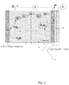
- the device used in the method of the present invention for the production of hydrogen peroxide in an aqueous solution or aqueous electrolyte by reduction of oxygen shown in fig. 1 comprises at least one anodic compartment 5 and at least one cathode compartment 15. If so desired a plurality of anodic and cathode compartments may be present as well. If a plurality of anode and cathode compartments is provided, they are preferably arranged in a unipolar arrangement, with a plurality of alternating positive and negative electrodes forming a stack separated by ion permeable membranes. In a unipolar design, electrochemical cells forming the stack are externally connected, the cathodes are electrically connected in parallel as well as the anodes.
- the anode or anodes 1 are immersed in an anode compartment comprising an aqueous anolyte fluid 2.
- the cathode or cathodes 10 are immersed in a cathode compartment comprising an aqueous catholyte fluid 12.
- the anodic compartment and cathodic compartment are in fluid communication to allow transport of cations, in particular transport of protons from the anodic compartment to the catholyte compartment, and transport of anions from the cathodic compartment to the anodic compartment.
- anolyte fluid any anolyte considered suitable by the skilled person may be used.
- any aqueous electrolyte conventionally used in electrochemical reduction reactions may be used.
- the anolyte may for example comprise an aqueous solution of an electrolyte selected from the group of sulphates, phosphates, chlorides and mixtures of two or more of these compounds.
- the anolyte chamber may comprise a supply member for feeding anolyte fluid.
- the catholyte chamber may comprise a supply member for feeding catholyte fluid.
- the catholyte may be different from the anolyte, but anolyte and catholyte may also be the same.
- Suitable catholyte materials include an aqueous solution of an electrolyte selected from the group of sulphates, phosphates, chlorides and mixtures of two or more of these compounds.
- the device used in the method of the present invention may be operated in batch or continuous mode.
- electrolyte When operated in continuous mode, electrolyte may continuously be recirculated or fresh electrolyte may be supplied, in particular to the cathode compartment.
- electrolyte containing the reaction product When operated in batch mode, electrolyte containing the reaction product may be withdrawn in particular from the cathode compartment and replenished by a corresponding batch of fresh electrolyte.
- the anode and cathode compartment 5, 15 may be made of any material considered suitable by the skilled person, but are preferably made of a polymeric material. Suitable materials include polyvinylidene difluoride (PVDF), polytetrafluorethylene (PTFE), ethylene tetrafluoroethylene (EFTE), polyvinylchloride (PVC), chlorinated polyvinyl chloride (CPVC), polyacrylate, polymethylmethacrylate (PMMA), polypropylene (PP), high density polytethylene, polycarbonate and blends or composites of two or more of these compounds.
- PVDF polyvinylidene difluoride
- PTFE polytetrafluorethylene
- EFTE ethylene tetrafluoroethylene
- PVC polyvinylchloride
- CPVC chlorinated polyvinyl chloride
- PMMA polymethylmethacrylate
- PP polypropylene
- high density polytethylene polycarbonate and blends or composites of two or more of
- the anode and cathode compartment 5, 15 are separated from each other by an ion permeable membrane 11 to control exchange of cations and anions between both compartments, as described above.
- the ion-permeable membrane 11 separating the anode and cathode compartment 5, 15 may be reinforced with a rigid support, for example a rigid support made of a sheet, a fleece, which may be woven or non-woven or otherwise made of a porous polymer or a web or a mesh of metal fibres or metal fibres arranged in a woven or non-woven structure.
- the cathode 10 used is preferably a gas diffusion electrode, to ensure a suffiently high mass transfer of oxygen to the electrochemically active layer present at the cathode, and a sufficiently high reaction yield, taking into account the limited solubility of oxygen in water.
- the gas diffusion electrode is preferably a multilayered electrode comprising a current density distributor 3 for supplying electric current to an electrochemically active layer 4 deposited on top of the current distributor.
- the electrochemically active layer 4 is chosen such that it is active in the catalysis of the reduction of oxygen to hydrogen peroxide.
- the electrochemically active material 4 is preferably a material which has a higher electric conductivity than the current density distributor. This permits the electrochemically active material to take away or bring the electron from and to the current density distributor.
- electrochemically active layer is meant a layer of a material in which the electrochemical reduction of oxygen to hydrogen peroxide takes place, in particular a layer of a material having high electrical conductivity, which is porous to gas, in particular oxygen, and electrolyte.
- Electrode particles comprising surface functional group with acidic protons, having a high specific surface area as measured by the BET method described in ASTM D5665, in particular carbon particles selected from the group of graphite, carbon nanotubes, graphene, carbon black, activated carbon or synthetic carbons.
- the gas diffusion electrode that is used as the cathode 10 preferably comprises a current density distributor 3 or a current distributor, which may be made of any material and form considered suitable by the skilled person.
- a current density distributor 3 or a current distributor, which may be made of any material and form considered suitable by the skilled person.
- a mesh type current density distributor having a porous mesh received in a circumferential electrically conductive frame or an array of several porous meshes.
- the current density distributor is connected to a source of electric energy along a current feeder, for supplying electrical energy to the current density distributor.
- the mesh comprises a plurality of electrically conductive paths.
- mesh a woven, knitted, braided, welded, expanded mesh, bars or threads of electrically conductive fibers, having holes between the bars, fibers or threads to provide porosity, or a plate, sheet, foil, film made of an electrically conductive material having a plurality of perforations or holes to provide porosity.
- the wording "mesh” is meant to include a square meshes with a substantially rectangular shape and orientation of the conductive wires and insulating threads, but the mesh may also be tubular, or a coil film, or a otherwise shaped three-dimensional materials.
- Still other types of meshes suitable for use with this invention include perforated sheets, plates or foils made of a non-conductive material, having a plurality of wires or threads of a conductive material interlaced in the direction parallel to the current flow.
- a further type of mesh suitable for use with the present invention includes lines/wires of a conductive material, which extend parallel to the current flow direction, printed on a perforated sheet, foil or plate.
- the layer of electrochemically active material 4 i.e. the layer which is catalytically active in the reduction of oxygen to hydrogen peroxide as described above, is preferably applied to the side of the current density distributor facing the gas phase.
- the electrochemically active layer usually has an interface with electrolyte on one surface (i.e. the side facing the current distributor) and a water repellant (hydrophobic gas diffusion) layer 13 on the other.
- the electrochemically active layer 4 may be coated on the side facing the gas phase 13, with a water repellant layer 13 or a hydrophobic gas diffusion layer to minimize the risk of water leaking through the electrode into the gas phase.
- This water repellant layer 13 may also be deposited on top of the electrochemically active layer 4.
- Suitable materials for use as the water repellant layer include polyvinyldifluoride (PVDF), polytetrafluoroethylene (PTFE or Teflon), PSU, but other materials considered suitable by the skilled person may be used as well.
- the device preferably comprises a supply member for supplying an oxygen containing gas to the side of the cathode comprising the electrochemically active layer.
- Any oxygen containing gas considered suitable by the skilled person may suitably be used. Examples include pure oxygen, a mixture of oxygen with one or more inert gases for example N 2 , Ar, He or a mixture thereof, air, etc.
- the gas supply rate may be adapted, to permit controlling the hydrogen peroxide production rate and yield.
- the cathodic compartment comprises on a side 6 opposite the side of the cathode comprising the electrochemically active layer 4, an inlet for supplying at least one weak protonic electrolyte, preferably an aqueous electrolyte.
- the flow rate with which the weak protonic electrolyte is variable may be adapted taking into account the oxygen conversion rate to hydrogen peroxide.
- the anode 1 used in the method of this invention may be a conventional electrode, or may be a gas diffusion electrode similar to the cathode.
- the method may further comprise means for creating convective mass transfer in the catholyte. This may improve H 2 O 2 reclamation from the electrochemically active layer, by increasing convective mass transfer at the catholyte site. This may also improve replenishment of H + at the position of the acidic active sites present on the surface of the electrochemically active layer.
- Means for creating convective mass transfer may also be provided at the anolyte site, to promote proton transfer towards and through the ion permeable membrane.
- the means for creating convective mass transfer may comprise those known to the skilled person, for example a stirrer, gas supply, a spacer material capable of creating turbulent flow conditions.
- the method of this invention may also comprise means for optimizing the oxygen residence time at the cathode. This may be achieved by the presence of means for creating convective mass transfer in the gas phase at the cathode.
- a Bio-Logic VMP3 potentiostat/galvanostat and frequency response analyzer was used in order to perform the electrochemical measurements.
- EC-Lab v.10.23 software was used for data acquisition and analysis.
- Electrochemical Impedance Spectroscopy was recorded at a frequency range from 10 kHz to 10 mHz, with 6 points per logarithmic decade, using an amplitude of 10 mV. Validity of the data was verified by using the Kramers-Kronig transforms. Data consistency was assessed by visual inspection of successful regression to experimental data with several electrical analogues, composed of Voigt elements (Dominguez-Benetton et al., 2012). Subsequently, cyclic voltammetries (CV) were recorded in 3 cycles at 1, 10 and 100 mV s-1, respectively, in a potential range from - 0.450 to 0.450 V vs Ag/AgCl.
- EIS Electrochemical Impedance Spectroscopy
- Reagent A was prepared by mixing 33 g potassium iodide, 1.0 g sodium hydroxide, and 0.1 g ammonium molybdate tetrahydrate dissolved and diluted into 500 mL deionized water. This solution was kept in dark conditions to inhibit the oxidation of I-. If the solution becomes colored, it should be remade.
- Reagent B was prepared by 10.0 g of potassium hydrogen phthalate (KHP) dissolved in deionized water and diluted to 500 mL.
- KHP potassium hydrogen phthalate
- the standard calibration curve was prepared from known concentrations of H 2 O 2 . 60 ⁇ L of 30% H 2 O 2 were mixed with 100 mL of deionized water, in a volumetric flask. The concentration of this standard is 200 mg L -1 H 2 O 2 . The series of dilutions were done by taking an appropriate amount of H 2 O 2 solution for the desired concentrations, as shown in Table 1. Table 1:- mL of 200 mg L-1 H 2 O 2 standard Final volume with deionized water (mL) Known concentrations of H 2 O 2 for calibration curve. H 2 O 2 concentration in standard samples (mg L -1 ) 0.0 0.0 100 0.5 0.25 100 1.0 0.50 100 2.0 1.0 100 3.0 1.5 100
- CeO 2 at 4% by weight on the carbon support material was prepared by using the PPM (Polymeric Precursor Method).
- Precursor solution was prepared with 40 g of citric acid (CA) and 320 g of ethylene glycol (EG) at a 50:400 wt% ratio, at 60 °C.
- the catalyst was prepared by adding 0.8 g of metal into precursor solution, to satisfy 1:50:400 (Metal:CA:EG) ratio. 19.2 g of activated carbon were added into the resin. This mixture was homogenized in an ultrasonic bath for 60 min and thermally treated at 400 °C for 2 h, under N2 atmosphere.
- the PPM is used to produce the catalyst with a high surface area, to effectively mix different metal ions and to produce stable metal-chelate complexes to enhance H2O2 production (Assumpçao MHMT et al. 2012).
- Electrodes with and without catalyst were prepared according to the method described by (Alvarez-Gallego Y et al. 2012).
- the multilayered electrodes consisted of a current density distributor (metal gauze), with a layer of an electrocatalyst on a carbon support embedded in a porous polymer matrix applied on one side, and a hydrophobic gas-diffusion layer was present on the opposite side .
- a cold-rolling method was utilized for the preparation of the gas diffusion cathodes, from carbonaceous powders and polymer binder.
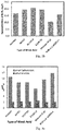
- the carbonaceous powders and combinations thereof utilized to fabricate the different types of electrodes object of this study are described in Table 2.
- Stainless steel 316L gauze (wire diameter ⁇ 100 m, mesh 44) was used as the current density distributor.
- Polyvinilydenefluoride (PVDF) was chosen as polymer binder, for both the active layer and the hydrophobic gas-diffusion layer (HGDL).
- the hydrophobic particles in the hydrophobic backing were FEP 8000.
- a typical HGDL is composed of 50% by weight PVDF and 50% by weight of FEP 8000.
- the percentage of the carbon materials for the fabrication of electrodes was identified on the basis of performance during the cold calendaring of carbon materials.
- the maximum possible percentage of carbon to incorporate with Norit was found 30% by weight, due to manufacturing restrictions.
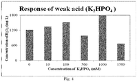
- Example 1 was repeated, this time using K 2 HPO 4 as a weak acid, in varying concentrations as illustrated in Figure 4 .
- Example 2 was repeated, this time using a cathode whose active layer consisted of 80% graphite and 20% polymer binder.
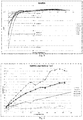
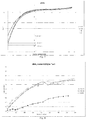
- KH 2 PO 4 was selected as weak acid, in varying concentrations as illustrated in Figures 5 and 6 and in table 3 below. From table 3 it may be observed that there is a dependence between the concentration of KH 2 PO 4 used and the power administrated to the system for the electrosynthseis reaction to take place, the power density required was up to 40% of the value without KH 2 PO 4
- Example 1 was repeated, this time using citric acid as a weak acid, in varying concentrations as illustrated in figures 7 and 8 and in table 4 below. From table 4 it may be observed that the concentration of citric acid/citrate electrolyte did not affect substantially the power suministrated to the system for the electro synthesis reaction to take place. From Fig 8 it can be appreciated that, in contrast with experiments using phosphate as electrolyte (example 3), with citrate H 2 O 2 mole production did not vary substantially when citrate concentration increases from 100 mM to 500 mM, or even increased (making the process less favourable).
- Figure 10 shows the evolution of the pH of the catholyte with time, for varying concentrations of citric acid as weak protonic electrolyte.
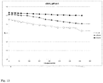
- Figure 11 shows the evolution of the pH of the catholyte with time, for varying concentrations of HKH 2 PO 4 as weak protonic electrolyte.
Landscapes
- Chemical & Material Sciences (AREA)
- Engineering & Computer Science (AREA)
- Organic Chemistry (AREA)
- Electrochemistry (AREA)
- Chemical Kinetics & Catalysis (AREA)
- Materials Engineering (AREA)
- Metallurgy (AREA)
- Water Supply & Treatment (AREA)
- Environmental & Geological Engineering (AREA)
- Hydrology & Water Resources (AREA)
- Life Sciences & Earth Sciences (AREA)
- Inorganic Chemistry (AREA)
- General Chemical & Material Sciences (AREA)
- Electrolytic Production Of Non-Metals, Compounds, Apparatuses Therefor (AREA)
Description
- The present invention relates to a method for the production of hydrogen peroxide in an aqueous solution by electrochemical reduction of oxygen in a cathodic compartment of the device, the cathodic compartment comprising at least one cathode and an aqeous catholyte fluid, the device further comprising at least one anodic compartment in fluid communication with the cathodic compartment, wherein the cathode comprises a porous gas diffusion electrode one side of which comprises a carbon based electrochemically active layer capable of catalyzing the reduction of oxygen to hydrogen peroxide, according to the preamble of the first claim.
- Hydrogen peroxide (H2O2) is a strong oxidizing agent, which is commercially available in a wide range of concentrations. Hydrogen peroxide finds application in numerous industrial processes of a.o. textile, pulp and paper, chemical, food processing, and pharmaceutical industries, industrial processing, treatment of waste water, mining industry and medical applications. The widespread applications of H2O2 and the disadvantages of the existing production processes (anthraquinone, alcohol auto oxidation, direct production) have incurred an enhanced interest for processes which involve an electrochemical synthesis of H2O2.
- Early developed electrolytic processes for the production of hydrogen peroxide made use of the catalytic hydrogenation of substituted 2-alkyl-anthraquinone and subsequent reaction of the resulting 2-alkyl antraquinone with molecular oxygen to yield hydrogen peroxide and 2-alkyl antraquinone. Current commercial hydrogen peroxide production processes which supply the present demand of H2O2 worldwide, use a multistage anthraquinone oxidation. Disadvantages of this process are situated in terms of energy consumption, waste management, high production cost, adverse sustainability due to the scarcity of resources, and risks related to health and safety (Ntainjua EN et al. 2011). Another process for producing H2O2 is based on the primary and secondary partial oxidations of alcohols (Harris CR et al. 1949, Rust FF 1955). Although alcohol oxidation could provide an alternative to the anthraquinone oxidation, the purity of the hydrogen peroxide produced is not better, mainly due to the high solubility of H2O2 in alcohol.
- The simplest method for the production of hydrogen peroxide is a direct synthesis by the direct reaction of H2 and O2. Such a process could be the future technology to replace the auto oxidation process in the presence of a suitable catalyst (Hoelderich WF et al. 2000). Nonetheless, a production process based on the direct reaction of H2 and O2 has limitations. H2/O2 mixtures are explosive (Samanta C 2008, Edwards J 2009), there is a risk to the occurrence of simultaneous unwanted side reactions involving decomposition of hydrogen peroxide, and the reduction of H2O2 solvent to name a few. Although it is assumed that the use of an active catalyst strictly based on palladium nano particles deposited on carbon, with an appropriate solvent (in general an alcohol), would limit side reactions (Samanta C 2008, Schlummer B et al. 2004), such a process is energy consuming and safety issues are still an important point of concern. Other catalytic processes carried out in the presence of a group VIII catalyst or an Ir based catalyst are equally inherently unsafe as they use potentially explosive H2-O2 mixtures in pressurized reaction vessels. An important issue is that in all of the above described processes, H2O2 decomposition reactions are intensely triggered and even when the H2O2 produced would be stabilized, the performance of the catalyst appears to be insufficient to provide an economically feasible process. Synthesis routes employing a Pd based catalyst seem to be more safe, but even in the presence of a quinone co-catalyst the H2O2 yield remains moderate (Vulpescu et al. 2004).
- The existing industrial processes for hydrogen peroxide production further present significant problems of transport and storage costs, as well as storage risks, since hydrogen peroxide is produced in bulk quantities, which need to be transported to the hydrogen peroxide user and stored by this user. On-site production of hydrogen peroxide would solve these problems and would permit to reduce storage and transportation costs, as well as the associated hazards, which may even be more important.
- Electrochemical synthesis of H2O2 may proceed over an oxygen reduction reaction. However, the low solubility of oxygen in aqueous solutions is one of the main problems limiting mass transfer rates in the oxygen reduction reaction. The use of gas diffusion electrodes, with a large electrochemically active reaction area, allowing for higher mass transfer rates, appeared to offer a promising option (Forti et al. 2007a ; Forti et al. 2007b). By using gas diffusion electrodes, concentrations up to 0.1-7 wt. % could be achieved (Yamanaka et al. 2011). The active layer of gas diffusion electrodes used for the cathodic reduction of oxygen to H2O2 is often made of carbon based materials, because of their large specific surface area, strong corrosion resistance and acceptable cost. Precious metals such as Pt, Ce, Ru, Ir and Rh are the most commonly used catalytic materials when O2 reduction is carried out in an acidic electrolyte, whereas Mn, Ag, Ni foam, carbon or Ni mesh are frequently used to catalyse the oxygen reduction reaction in alkaline electrolytes (Giomo et al. 2008, Assumpçao et al. 2012). Some authors have used systems which do not employ metal catalysts, however they make use of carbon nano powders, which pose environmental and toxicity concerns (Yamanaka et al. 2011). The major factor contributing to the costs of operation for an electrochemical H2O2 production is electricity consumption.
- Competitive H2O2 production processes should be able to produce H2O2 in a concentration of at least 0.1 wt. %, preferably at least 1.0 wt. %, while keeping electricity input as low as possible.
-
US7754064 discloses a device and a process for producing H2O2 from H2O using electrosynthesis. The device comprises an anolyte chamber coupled to at least one anode, which comprises a conductive, catalytically active material for example titanium, platinum, gold, silver, copper, steel, graphite, silicon, anodized titanium, reticulated vitreous carbon, or combinations thereof or a substrate coated with a metal oxide or a doped metal oxide. The anolyte feed stream contains an inert electrolyte dissolved in water, for example a sulfate, phosphate, citrate, acetate or nitrate of sodium or potassium, hydrochloric acid, hydrobromic acid, hydrogen potassium sulfate, sulfuric acid, nitric acid, citric acid, acetic acid, or combinations thereof. The catholyte chamber is coupled to at least one cathode, which is made of a conductive and catalytically active material, for example carbon, graphite, glassy carbon, reticulated vitreous carbon, carbon felt, gold, or combinations thereof. The catholyte feed stream comprises an electrolyte such as sodium chloride and/or other suitable ions in solution. A central chamber prevents migration of anions from the catholyte to the anolyte chamber, and thereby counteracts formation of unwanted side-products such as chlorine. The central chamber also controls the pH balance between the catholyte chamber and the anolyte chamber, and may thereto comprise an acid buffer and/or a sodium or potassium containing electrolyte. - In the process of
US7754064 , protons formed by oxidation of the water containing anolyte stream move through the central chamber to the catholyte chamber, where the oxygen containing catholyte feed stream is reduced to form peroxide ions, which react with the protons to form a catholyte exit stream containing hydrogen peroxide. As protons migrate from the anolyte chamber to the central chamber, the acidity of the electrolytic medium in the central chamber increases. - The H2O2 yields that may be achieved with the device and method disclosed in
US7754064 are however limited, which may compromise the economic feasibility of the process. - The method for producing hydrogen peroxide disclosed in
US6712949 involves oxidation of water at the anode of an electrolytic cell to form oxygen and protons, which are transported to the cathode in a compartmentalized electrolytic cell to prevent destruction of peroxide at the counter electrode or anode. Simultaneously, the redox catalyst of the cathode is continuously reduced by the protons formed in the anodic water reaction. Oxygen introduced at the cathode is reduced to hydrogen peroxide, preferably at current densities of at least 50 mA/cm2. The redox catalyst which is bound to the cathode becomes oxidized, and is continuously regenerated electrochemically by cathodic reduction. The reaction medium comprises electrolyte solutions with strong mineral acids, such as hydrochloric acid, nitric acid, phosphoric acid, sulfuric acid, etc. Alternatively, soluble salts may be used in place of the foregoing acids. -
US6254762 discloses an electrolytic cell for producing hydrogen peroxide. The cell is partitioned into an anode and a cathode chamber with a diaphragm, and has a solid ion-conductive material packed in at least one of the anode and cathode chambers for electrically connecting the diaphragm to the anode or cathode. Pure or ultrapure water is supplied to the cathode chamber, which is used as solution chamber and where hydrogen peroxide is to be generated. The anode chamber may be used as either a gas chamber or a solution chamber. However, virtually no electrolyte is dissolved. Oxygen-containing gas is supplied to the cathode, hydrogen gas or water is supplied to the anode. -
US8377384 discloses an electrochemical cell arrangement for the generation of hydrogen peroxide, comprising anode and cathode electrodes with a cation exchange membrane disposed between them. An aqueous salt solution is supplied to the anode compartment and water and oxygen are supplied to the cathode compartment. An aqueous salt solution may be supplied to enhance conductivity. -
US8591719 discloses an electrolysis cell for producing a 1 to 5 wt. % hydrogen peroxide containing aqueous solution, from oxygen. A separator divides the cell into a cathodic compartment and an anodic compartment. The separator comprises a first surface facing the cathodic compartment equipped with a gas-diffusion cathode comprising a catalytic porous film for the reduction of oxygen to hydrogen peroxide and with a second surface facing the anodic compartment. The cathodic compartment comprises an oxygen feed, the anodic compartment comprises an aqueous anolyte feed. The anode is equipped with a catalyst for oxygen evolution. An electric current is applied to the cell while establishing a water flow-rate of 10 to 100 l/h.m2 across the separator. -
US6.387.238 discloses a method for preparing an antimicrobial solution containing per-acetic acid. The method includes the electrolytic generation of hydrogen peroxide in the cathode chamber by reduction of oxygen in water and reacting such reduction species with an acetyl donor to form per-acetic acid. As a cathode use is made of a gas diffusion electrode, An oxygen containing gas, such as air is used as oxygen source. A buffering agent is added to maintain the pH of the alkaline electrolyte between 5 and 14, more preferably between 7 and 9, most preferably between 7 and 7.5. With "alkaline" is meant that the electrolyte has a higher pH than the electrolyte that is fed to the anode chamber. Suitable acidic buffering agents include acetic acid or citric acid, acetic acid having a pKa of 4.76, citric acid having successive pKa's of respectively 3.13, 4.76 and 6.39. -
US5.358.609 discloses an apparatus for producing hydrogen peroxide by reduction of oxygen produced by the oxidation of water. The devices comprises a water oxidizing anode, a gas-diffusion cathode for reducing oxygen to hydrogen peroxide. The anode and cathode compartment both contain the same alkaline electrolyte, in particular an aqueous sodium hydroxide solution. The alkaline catholyte may be chosen from aqueous solutions of salts such as sodium carbonate or sodium borate. It is explained that acid is not consumed because H+ ions are generated by dissociation of water.US5.358.609 is however silent on the pH of the catholyte - The present invention seeks to provide a method with which H2O2 may be produced from an oxygen containing gas at industrially interesting yields.
- This is achieved according to the present invention with a method according to
claim 1. - The inventors have surprisingly found that the presence in the catholyte fluid of a weak protonic electrolyte having a pKa which is at least one unit higher than the pH of the catholyte at the onset of the electrochemical reduction of oxygen to hydrogen peroxide, results in an increased amount of H2O2 produced per time unit. With 'the onset of the electrochemical reduction of oxygen to hydrogen peroxide' is meant that the pH is measured at the start of the electrochemical reduction of oxygen. With 'the onset of the electrochemical reduction of oxygen to hydrogen peroxide' is also meant that the pH is measured before oxygen has been supplied to the catholyte, or before conversion of oxygen to hydrogen peroxide has occurred.
- The inventors have not only found that the rate with which H2O2 is produced may be accelerated, but also that the H2O2 product yield may be increased. Without wanting to be bound to this theory, the inventors believe that the weak protonic electrolyte acts as a catalyst in the conversion of oxygen to hydrogen peroxide at the cathode.
- The inventors have also observed that the presence of the weak protonic electrolyte has the effect that the cathode polarization potential at which hydrogen peroxide can be formed at a given amount of current may be reduced, without adverse effect to the hydrogen peroxide yield and production rate. Furthermore, it has been found that the presence of the weak protonic electrolyte may not only lead to an increased conductivity of the catholyte, but also that the current density over the cathode may be increased, which explains the observed higher H2O2 yield.
- Although some of the weak protonic electrolytes may have the ability to control or minimize pH variations in the course of the oxygen reduction reaction to a certain extent, in the present invention the pH is left to evolve with time, and the reaction medium will not contain a buffering agent. In the absence of a buffering agent, the pH of the catholyte will usually increase in the course of the reaction as may be understood from reactions (2), (3) and (4) below. If it is desired to control the pH within a certain range, it may be considered to operate the device in a continuous mode and to continuously supply fresh catholyte, in particular fresh electrolyte, or it may be considerd to supply batches of fresh catholyte, in particular to supply fresh electrolyte when operating the device or reaction in a batch mode.
- The present invention shows the advantage that the presence of the claimed weak protonic electrolyte in the catholyte fluid may render the process of this invention particularly suitable for use in or for direct coupling to processes employing biological material or to other processes which are highly pH dependent.
- The present invention thus provides an alternative to existing processes for the production of hydrogen peroxide by electrochemical reduction of oxygen.
- According to the present invention weak protonic electrolytes are understood to comprise those electrolytes whose pKa is at least one unit higher than the pH of the catholyte, so that a desired minimum degree of dissociation of the weak electrolyte in the catholyte may be ensured at the onset of the reaction. In a preferred embodiment, the weak protonic electrolyte is selected such that it has a pKa which is at least 1.25 units higher than the pH of the catholyte at the onset of the electrochemical reduction of oxygen, preferably at least 1.50 units higher, more preferably at least 2.0 units higher than the pH of the catholyte.
- With a weak protonic electrolyte is meant according to the invention, either a weak protonic acid or a weak protonic base, which is present in the catholyte in a partially dissociated state. Weak protonic electrolytes suitable for use with this invention include weak mono protonic acids and weak mono protonic bases, but also weak polyprotonic acids and weak polyprotonic bases.
- According to a first preferred embodiment, the weak electrolyte is a weak protonic acid, in particular a weak polyprotonic acid. A weak monoprotonic acid is a protonic acid which only partially dissociates in aqueous medium :
HA(aq) ↔ H+ (aq) + A- (aq)
- The dissociation constant of a weak monoprotonic acid may be represented by the formula below :

- A weak polyprotonic acid is a weak acid which has more than one ionisable proton per molecule. A weak polyprotonic acid may be represented by the chemical reaction :
HnA ↔ Hn-1A- + H+
- Examples of weak protonic acids suitable for use with the present invention include those which have a pKa in the range of 2.0 ≤ pKa ≤8.0, in particular a pKa in the range of 3.0 ≤ pKa ≤ 7.0, more preferably about 7.0. The weak protonic acid will however be chosen such that the pKa of the acid is at least one unit higher than the pH of the catholyte at the onset of the reduction reaction of oxygen to hydrogen peroxide. Examples of weak protonic acids suitable for use with the device and method of the present invention include the weak protonic acids selected from the group of weak organic and weak inorganic protonic acids, in particular acetic acid, citric acid, oxalic acid, lactic acid, gluconic acid, ascorbic acid, formic acid, glycolic acid, potassium monohydrogen phosphate, potassium dihydrogen phosphate, ammonium chloride, boric acid, sodium hydrogen sulphate, sodium hydrogen carbonate, phosphoric acid, ammonium chloride, and mixtures of two or more hereof. However other weak acids considered suitable by the skilled person may be used as well. Thereby the weak protonic acid will be chosen such that its pKa is at least one unit higher than the pH of the catholyte at the onset of the oxygen reduction reaction to hydrogen peroxide. The use of phosphoric acid is particularly preferred.
- According to a second preferred embodiment of this invention, the weak protonic electrolyte is preferably a weak protonic base. A weak protonic base is understood to include a base that does not fully ionize in an aqueous solution or those bases in which protonation is incomplete:
BH+ ↔ B + H+
represents the dissociation reaction of a monoprotonic base. - Examples of weak protonic bases suitable for use with the device and method of the present invention include those which have a pKa of between 6.0 ≤ pKa ≤ 12.0, in particular 7.0 ≤ pKa ≤ 11.0. Thereby, the weak protonic base will be chosen such that it has a pKa which is at least one unit higher than the pH of the catholyte at the onset of the oxygen reduction reaction. Examples of weak protonic bases suitable for use with this invention may be organic compounds or inorganic compounds, for example compounds selected from the group of ammonia, trimethylammonia, ammoniumhydroxide, pyridine, but also the conjugated bases of acetic acid, citric acid, oxalic acid, lactic acid, gluconic acid, ascorbic acid, formic acid, glycolic acid, potassium mono-hydrogenphosphate, potassium di-hydrogenphosphate, ammonium chloride, boric acid, sodium hydrogensulphate, sodium sulphate, sodium hydrogen carbonate, or a mixture of two or more of the afore mentioned compounds. However other weak protonic bases considered suitable by the skilled person may be used as well.
- In the method of this invention, the cathode comprises a porous gas diffusion electrode, wherein one side of the gas diffusion electrode comprises a layer of at least one electrochemically active material capable of catalyzing the reduction of oxygen to hydrogen peroxide. Porous gas diffusion electrodes are well known to the skilled person and are for example disclosed in Y. Alvarez-Gallego et al, Electrochimica Acta, 2012, vol. 82, p. 415-426.
- The electrochemically active material suitable for use within the cathode, and having a catalytically active surface capable of catalyzing the reduction of oxygen to hydrogen peroxide are generally, may be one of the frequently used materials, generally known to the skilled person . Preferred are those materials which have a surface comprising protonic acid functional groups. Particularly preferred are those materials which comprise electrically conductive particles of carbonaceous origin, more preferably those comprising electrically conductive particles of carbonaceous origin with a catalytically active surface comprising a plurality of protonic acid groups. The use of a porous carbon based material as or in the electrochemically active layer is preferred, because of its catalytic activity in combination with a reasonable cost and abundant availability in comparison to other materials.
- Other electrochemically active materials suitable for use with this invention include carbonaceous materials the surface of which has been chemically modified to adapt its catalytic activity and compatibility with the reaction medium. Without wanting to be bound by this theory, it is believed that the presence of oxygen-containing functional groups support the oxygen reduction reaction to hydrogen peroxide. Particularly preferred carbon materials have a surface with quinone-type functional groups.
- The voltage difference between the anode and cathode, induces at the cathode a dissociation of the water contained in the catholyte. It is assumed that the OH- ions which originate therefrom are capable of diffusing through the porous electrochemically active material of the cathode towards the bulk of the catholyte. This may give rise to a local increase of the pH in the vicinity of the active surface of the carbonaceous material, thus inducing dissociation of the protonic acid groups present on the surface :
C*-RH + OH- → C-R*- + H2O (1).
wherein C*-RH represents a protonic acidic group present on the active surface of the catalytically active material. - It is believed that the protonic acidic functional groups present on the catalytically active surface of the carbonaceous material, in particular acidic functional groups of the type R-H, may partly dissociate at a corresponding pH and thereby become available for neutralization of the thus formed OH- group. The inventors also believe that the thus dissociated surface groups C-R*- are active in the electro-synthesis of H2O2, because of their high affinity for the oxygen supplied to the cathode. The presence of weak acid is believed to replenish the H+ that may have reacted in reaction (1) above, thereby restore the acid-base equilibrium of the catalytically active sites and ensure that variations in the pH of the catholyte may be reduced to a minimum.
- The inventors have observed that optimum acceleration of the oxygen reduction reaction to hydrogen peroxide as represented by chemical reactions (2), (3), (6) below may be achieved if the pH of the catholyte at the onset of the oxygen reduction reaction is at least 2.5 and the weak protonic electrolyte has a pKa of at least 3.5. More preferably the pH of the catholyte at the onset of the oxygen reduction reaction is about 2.7 and the weak protonic electrolyte has a pKa of 3.7 or more.
- Without wanting to be bound by this theory, the inventors believe that the catalytic effect induced by the weak protonic electrolyte can be explained as outlined in the reactions (2), (3) and (6) below. The weak protonic electrolyte, in particular the weak protonic acid is believed to provide an immediate proton source to the catalytically active surface, which then becomes available for reaction with oxygen to form hydrogen peroxide. H+ transport on the electrochemically active surface of the electrode as represented by reactions (2), (3) and (6) or alternatively (4), (5) and (6) is believed to be significantly faster than H+ transport in solution. It is further believed that optimal reaction rate of reactions (2), (3) and (6) or alternatively (4) and (5) may be obtained at a pH of at least 2.5, preferably a pH of about 2.7.
4C* - R- + O 2(aq) + 2H 2 O + 4e- → 4C* - ROOHads (2)
C* - ROOH + H + + e - → H 2 O 2 + C* - R- (3)
- In the presence of the weak acid,
reaction 3 would be as follows:
C* - ROOH + C* - RHads + e- → H 2 O 2 + 2C* - R- (6)
- With H 2 PO 4- as an example of a weak acid, dissociation can be described as follows :
C* - R- + H 2 PO 4 + e- → C* - RHads + HPO 4 2- (4)
C* - R- + HPO 4 2- + e- - C* - RHads + PO 4 3- (5)
- The inventors have observed that the reactions described above take place when use is made of a weak acid, the pKa of which is at least one unit higher than the pH of the catholyte.
- The inventors have also observed that reactions (4), (5) and (6) proceed at a much higher reaction rate than reaction (3) alone, in other words, the sum of the reaction rates of reactions (4), (5) and (6) is higher than the reaction rate of reaction (3) alone.
- Suitable particles of carbonaceous origin include those having a small BET surface area, but preferred are those with a high specific surface area as measured by the BET method described in ASTM D5665, in particular carbonaceous particles selected from the group of graphite, carbon nanotubes, grapheme, carbon black, activated carbon or synthetic carbons. Preferred conductive carbonaceous particles have a BET surface area of at least 50 m2/g, preferably at least 100 m2/g, more preferably at least 200 or 250 m2/g, most preferably at least 500 m2/g.
- The above described electrochemically layer may be the only electrochemically active material present on the cathode. However, according to another embodiment, the above described electrochemically layer may function as a carrier for at least one other catalytic material, capable of catalyzing the reduction of oxygen to hydrogen peroxide. Materials capable of catalyzing this reaction include one or more metal selected from the group of noble metals, in particular one or more metals selected from the group of Pd, Pt, Ru, Rh, Ni, W, Fe, Se and alloys of two or more hereof, mixtures of two or more of the afore mentioned metals with their oxides, or organometallic compounds containing one or more of the afore mentioned metals. Frequently used catalysts are Pt based, and include Pt as well as PtO. Alternative catalysts suitable for use in the present invention include quinone and derivatives, transition metal macrocyclic compounds, transition metal chalcogenides and transition metal carbides.
- In order to ensure a sufficiently strong binding of the electrochemically active material to the surface of the current density distributor present in the cathode, a binder material may be used, preferably a binder of a polymeric material. The polymer binder may also function to bind particles with a hydrophilic and/or hydrophobic properties to the current density distributor. A wide variety of binder materials may suitably be applied. Examples of suitable binder materials include polymeric materials such as polysulphone, polyethersulphone, polyphenylenesulfide, polyvinylchloride, chlorinated polyvinyl chloride, polyvinylidene fluoride, polyacrylonitrile, polyethyleneoxide, polymethylmethacrylate or copolymers thereof, sulfonated polymers such as perfluorosulfonic acid for example materials available under the commercial name of Nafion, terpolymers of vinylidene fluoride, hexafluroropropylene, chlorotrifluoroethylene, PTFE and mixtures or blends of two or more of these materials. Other materials considered suitable by the skilled person may be used as well.
- In the method of this invention, the at least one anodic compartment and the at least one cathodic compartment are preferably separated from each other by means of an ion permeable membrane, preferably comprising a synthetic polymer material. The ion permeable membrane on the one hand ensures that cations, in particular protons, may migrate from the anode to the cathode compartment, and on the other hand serves as a gas barrier and therewith counteracts the occurrence of so-called chemical short cuts. The ion permeable membrane may also permit migration of anions from the cathode to the anode compartment. Suitable materials for use in ion permeable membranes include polyvinyldifluoride (PVDF), polytetrafluoroethylene (PTFE or Teflon), poly(ethene-co-tetrafluoroethene (EFTE), polyesters, aromatic polyamides, polyhenylenesulfide, polyolefin resins, polysulphone resins, perfltiolorovinyl ether (PFVE), tripropylene glycol, poly-1,3-butanediol or blends of two or more of these compounds. The ion permeable membrane will usually be a composite containing one or more of the afore-mentioned compounds and be obtained by dispersion of a metal oxide and/or a metal hydroxide in a solution of the polymer to increase the ionic conductivity. The ion permeable membrane may also comprise an ion exchange material if so desired.
- The present invention is further illustrated in the figures and description of the figures below.
-
Fig. 1 is a schematic view of the device used in the method of the present invention. -
Fig. 2 shows the steady state current density as a function of time for different oxygen-reducing gas-diffusion cathodes, with and without CeO2 catalyst, after 120 min of electrocatalytic production of hydrogen peroxide. N: Norit, V: Vulcan-Norit, AB: Acetylene Black-Norit. All electrodes were composed of a combination of 80% carbon mixture and 20% polymer (PVDF). -
Fig. 3 shows: Experiments with a cathode based on activated carbon particles in the active layer, using different concentrations of phosphate as electrolyte :-
Fig. 3a ) Concentration of H2O2, obtained as per CE. -
Fig. 3b ) Concentration obtained based on the analytical method. -
Fig. 3c ) pH of Anolyte and Catholyte.
-
-
Fig. 4 shows the analytical concentrations of the H2O2 obtained in the experiments of Example 2. -
Fig. 5 shows electrokinetic biasing curves plotted varying the potential of the cathode vs Ag/AgCl in the range -0.5 to 0.5 at a scan rate of 1 mV.s-1, experiments with a cathode based on graphite particles as electrocatalytically active material, using different concentrations of phosphate as electrolyte. -
Figure 6 shows H2O2 production as a function of reaction time and concentration of phosphate added to the catholyte. -
Fig. 7 shows the electrokinetic biasing curves plotted varying the potential of the cathode vs Ag/AgCl in the range -0.5 to 0.5 at a scan rate of 1 mV.s-1, experiments with a cathode based on graphite particles as electrocatalytically active material, using different concentrations of citrate as electrolyte. -
Fig. 8 shows H2O2 production as a function of reaction time and concentration of phosphate added to the catholyte. -
Fig. 9 shows experiments with a cathode based on graphite particles as electrocatalytically active material, using different concentrations of weak acid as electrolyte. a) moles produced after 4h experiment, using hydrogen phosphate as electrolyte; b) moles produced after 4h experiment, using citrate as electrolyte. -
Figure 10 shows the evolution of the pH of the catholyte with time, for varying concentrations of citric acid as weak protonic electrolyte. -
Figure 11 shows the evolution of the pH of the catholyte with time, for varying concentrations of HKH2PO4 as weak protonic electrolyte. - The device used in the method of the present invention for the production of hydrogen peroxide in an aqueous solution or aqueous electrolyte by reduction of oxygen shown in
fig. 1 , comprises at least oneanodic compartment 5 and at least onecathode compartment 15. If so desired a plurality of anodic and cathode compartments may be present as well. If a plurality of anode and cathode compartments is provided, they are preferably arranged in a unipolar arrangement, with a plurality of alternating positive and negative electrodes forming a stack separated by ion permeable membranes. In a unipolar design, electrochemical cells forming the stack are externally connected, the cathodes are electrically connected in parallel as well as the anodes. - The anode or
anodes 1 are immersed in an anode compartment comprising anaqueous anolyte fluid 2. The cathode orcathodes 10 are immersed in a cathode compartment comprising anaqueous catholyte fluid 12. The anodic compartment and cathodic compartment are in fluid communication to allow transport of cations, in particular transport of protons from the anodic compartment to the catholyte compartment, and transport of anions from the cathodic compartment to the anodic compartment. As anolyte fluid, any anolyte considered suitable by the skilled person may be used. In particular any aqueous electrolyte, conventionally used in electrochemical reduction reactions may be used. The anolyte may for example comprise an aqueous solution of an electrolyte selected from the group of sulphates, phosphates, chlorides and mixtures of two or more of these compounds. The anolyte chamber may comprise a supply member for feeding anolyte fluid. The catholyte chamber may comprise a supply member for feeding catholyte fluid. The catholyte may be different from the anolyte, but anolyte and catholyte may also be the same. Suitable catholyte materials include an aqueous solution of an electrolyte selected from the group of sulphates, phosphates, chlorides and mixtures of two or more of these compounds. - The device used in the method of the present invention may be operated in batch or continuous mode. When operated in continuous mode, electrolyte may continuously be recirculated or fresh electrolyte may be supplied, in particular to the cathode compartment. When operated in batch mode, electrolyte containing the reaction product may be withdrawn in particular from the cathode compartment and replenished by a corresponding batch of fresh electrolyte.
- The anode and
cathode compartment - The anode and
cathode compartment permeable membrane 11 to control exchange of cations and anions between both compartments, as described above. To improve structural integrity, the ion-permeable membrane 11 separating the anode andcathode compartment - The
cathode 10 used is preferably a gas diffusion electrode, to ensure a suffiently high mass transfer of oxygen to the electrochemically active layer present at the cathode, and a sufficiently high reaction yield, taking into account the limited solubility of oxygen in water. The gas diffusion electrode is preferably a multilayered electrode comprising acurrent density distributor 3 for supplying electric current to an electrochemically active layer 4 deposited on top of the current distributor. The electrochemically active layer 4 is chosen such that it is active in the catalysis of the reduction of oxygen to hydrogen peroxide. - The electrochemically active material 4 is preferably a material which has a higher electric conductivity than the current density distributor. This permits the electrochemically active material to take away or bring the electron from and to the current density distributor. With "electrochemically active layer" is meant a layer of a material in which the electrochemical reduction of oxygen to hydrogen peroxide takes place, in particular a layer of a material having high electrical conductivity, which is porous to gas, in particular oxygen, and electrolyte. Materials suitable for use as electrochemically active layer have been described above, and comprise electrically conductive carbon particles comprising surface functional group with acidic protons, having a high specific surface area as measured by the BET method described in ASTM D5665, in particular carbon particles selected from the group of graphite, carbon nanotubes, graphene, carbon black, activated carbon or synthetic carbons.
- The gas diffusion electrode that is used as the
cathode 10 preferably comprises acurrent density distributor 3 or a current distributor, which may be made of any material and form considered suitable by the skilled person. Preferably however, use is made of a mesh type current density distributor, having a porous mesh received in a circumferential electrically conductive frame or an array of several porous meshes. The current density distributor is connected to a source of electric energy along a current feeder, for supplying electrical energy to the current density distributor. The mesh comprises a plurality of electrically conductive paths. Within the scope of the present invention with "mesh" is meant a woven, knitted, braided, welded, expanded mesh, bars or threads of electrically conductive fibers, having holes between the bars, fibers or threads to provide porosity, or a plate, sheet, foil, film made of an electrically conductive material having a plurality of perforations or holes to provide porosity. The wording "mesh" is meant to include a square meshes with a substantially rectangular shape and orientation of the conductive wires and insulating threads, but the mesh may also be tubular, or a coil film, or a otherwise shaped three-dimensional materials. Still other types of meshes suitable for use with this invention include perforated sheets, plates or foils made of a non-conductive material, having a plurality of wires or threads of a conductive material interlaced in the direction parallel to the current flow. A further type of mesh suitable for use with the present invention includes lines/wires of a conductive material, which extend parallel to the current flow direction, printed on a perforated sheet, foil or plate. - One side of the
current density distributor 3 is coated with an electrochemically active layer 4 capable of catalyzing the reduction of oxygen to hydrogen. The layer of electrochemically active material 4, i.e. the layer which is catalytically active in the reduction of oxygen to hydrogen peroxide as described above, is preferably applied to the side of the current density distributor facing the gas phase. The electrochemically active layer usually has an interface with electrolyte on one surface (i.e. the side facing the current distributor) and a water repellant (hydrophobic gas diffusion)layer 13 on the other. - The electrochemically active layer 4 may be coated on the side facing the
gas phase 13, with awater repellant layer 13 or a hydrophobic gas diffusion layer to minimize the risk of water leaking through the electrode into the gas phase. Thiswater repellant layer 13 may also be deposited on top of the electrochemically active layer 4. Suitable materials for use as the water repellant layer include polyvinyldifluoride (PVDF), polytetrafluoroethylene (PTFE or Teflon), PSU, but other materials considered suitable by the skilled person may be used as well. - The device preferably comprises a supply member for supplying an oxygen containing gas to the side of the cathode comprising the electrochemically active layer. Any oxygen containing gas considered suitable by the skilled person may suitably be used. Examples include pure oxygen, a mixture of oxygen with one or more inert gases for example N2, Ar, He or a mixture thereof, air, etc. Preferably, in the device of this invention the gas supply rate may be adapted, to permit controlling the hydrogen peroxide production rate and yield.
- The cathodic compartment comprises on a side 6 opposite the side of the cathode comprising the electrochemically active layer 4, an inlet for supplying at least one weak protonic electrolyte, preferably an aqueous electrolyte. Preferably the flow rate with which the weak protonic electrolyte is variable and may be adapted taking into account the oxygen conversion rate to hydrogen peroxide.
- The
anode 1 used in the method of this invention may be a conventional electrode, or may be a gas diffusion electrode similar to the cathode. - The method may further comprise means for creating convective mass transfer in the catholyte. This may improve H2O2 reclamation from the electrochemically active layer, by increasing convective mass transfer at the catholyte site. This may also improve replenishment of H+ at the position of the acidic active sites present on the surface of the electrochemically active layer. Means for creating convective mass transfer may also be provided at the anolyte site, to promote proton transfer towards and through the ion permeable membrane. The means for creating convective mass transfer may comprise those known to the skilled person, for example a stirrer, gas supply, a spacer material capable of creating turbulent flow conditions.
- The method of this invention may also comprise means for optimizing the oxygen residence time at the cathode. This may be achieved by the presence of means for creating convective mass transfer in the gas phase at the cathode.
- The invention is further illustrated by the examples and comparative experiments described below.
- Experiments were performed in a half cell electrochemical reactor (
Figure 1 ), which contained a cathode (working electrode), a reference electrode, a counter electrode, and an ionic separator between working and counter electrode. Ag/AgCl 3 M KCl (+200 mV vs SHE) was used as reference electrode (Koslow Scientific), whereas a Pt disk fixed by laser welding over a titanium (Ti) plate was used as a counter electrode. Cathode and counter electrode were separated by liquid electrolyte and the separating membrane, Zirfon® (AGFA), unless otherwise stated. The electrodes and membrane have a projected electrode surface area of 10 cm2. - Sodium chloride solution (0.07 M) was used as both anolyte and catholyte, adjusted at pH 2.7 with 37% HCl. Air was fed to the cathodic air-compartment, at a flow rate of 402 mL min-1 and an overpressure of 10 mbar. Electrolyte recirculated in batch mode through the cells, with a peristaltic pump (Watson-Marlow), at 20 rpm speed (equivalent to ∼100 mL min-1). The experiments were carried out at room temperature (18±2 °C).
- A Bio-Logic VMP3 potentiostat/galvanostat and frequency response analyzer was used in order to perform the electrochemical measurements. EC-Lab v.10.23 software was used for data acquisition and analysis.
- Chronoamperometric experiments were carried out at a different set of independent potentials (0.350, 0.250, 0.150, 0.050, -0.050, -0.150, -0.250, and -0.350, V vs Ag/AgCl, respectively) during a period of 120 minutes at each condition. After that time, steady state was achieved in all systems.
- Afterwards, Electrochemical Impedance Spectroscopy (EIS) was recorded at a frequency range from 10 kHz to 10 mHz, with 6 points per logarithmic decade, using an amplitude of 10 mV. Validity of the data was verified by using the Kramers-Kronig transforms. Data consistency was assessed by visual inspection of successful regression to experimental data with several electrical analogues, composed of Voigt elements (Dominguez-Benetton et al., 2012). Subsequently, cyclic voltammetries (CV) were recorded in 3 cycles at 1, 10 and 100 mV s-1, respectively, in a potential range from - 0.450 to 0.450 V vs Ag/AgCl.
- A spectrophotometric method was used to determine the concentration of H2O2 in solution. Reagent A was prepared by mixing 33 g potassium iodide, 1.0 g sodium hydroxide, and 0.1 g ammonium molybdate tetrahydrate dissolved and diluted into 500 mL deionized water. This solution was kept in dark conditions to inhibit the oxidation of I-. If the solution becomes colored, it should be remade. Reagent B was prepared by 10.0 g of potassium hydrogen phthalate (KHP) dissolved in deionized water and diluted to 500 mL.
- The standard calibration curve was prepared from known concentrations of H2O2. 60 µL of 30% H2O2 were mixed with 100 mL of deionized water, in a volumetric flask. The concentration of this standard is 200 mg L-1 H2O2. The series of dilutions were done by taking an appropriate amount of H2O2 solution for the desired concentrations, as shown in Table 1.
Table 1:- mL of 200 mg L-1 H2O2 standard Final volume with deionized water (mL) Known concentrations of H2O2 for calibration curve. H2O2 concentration in standard samples (mg L-1) 0.0 0.0 100 0.5 0.25 100 1.0 0.50 100 2.0 1.0 100 3.0 1.5 100 - Further analysis was done by pipetting 3.0 mL of "Reagent A", 3.0 mL of "Reagent B", and 3.0 mL of standard or sample into a beaker. The contents of the mixture was allowed to react for a minimum of 5 minutes, before reading the absorbance of the solution at 351 nm (reference needed). Besides the known concentrations, problem sample obtained after chronoamperometric experiments were scanned to validate the absorbance wavelength.
- CeO2 at 4% by weight on the carbon support material was prepared by using the PPM (Polymeric Precursor Method). Precursor solution was prepared with 40 g of citric acid (CA) and 320 g of ethylene glycol (EG) at a 50:400 wt% ratio, at 60 °C. The catalyst was prepared by adding 0.8 g of metal into precursor solution, to satisfy 1:50:400 (Metal:CA:EG) ratio. 19.2 g of activated carbon were added into the resin. This mixture was homogenized in an ultrasonic bath for 60 min and thermally treated at 400 °C for 2 h, under N2 atmosphere. The PPM is used to produce the catalyst with a high surface area, to effectively mix different metal ions and to produce stable metal-chelate complexes to enhance H2O2 production (Assumpçao MHMT et al. 2012).
- Electrodes with and without catalyst were prepared according to the method described by (Alvarez-Gallego Y et al. 2012). The multilayered electrodes consisted of a current density distributor (metal gauze), with a layer of an electrocatalyst on a carbon support embedded in a porous polymer matrix applied on one side, and a hydrophobic gas-diffusion layer was present on the opposite side .
- A cold-rolling method was utilized for the preparation of the gas diffusion cathodes, from carbonaceous powders and polymer binder. The carbonaceous powders and combinations thereof utilized to fabricate the different types of electrodes object of this study are described in Table 2. Stainless steel 316L gauze (wire diameter µ100 m, mesh 44) was used as the current density distributor. Polyvinilydenefluoride (PVDF) was chosen as polymer binder, for both the active layer and the hydrophobic gas-diffusion layer (HGDL). The hydrophobic particles in the hydrophobic backing were FEP 8000. A typical HGDL is composed of 50% by weight PVDF and 50% by weight of FEP 8000.
Table 2: Carbon material used for cathode production (% wt) PVDF (% wt) Metallic Catalyst CeCl2 (% wt) 1 Norit (80) 20 - 2 Norit (76) 20 4 3 Norit (50), Vulcan (30) 20 - 4 Norit (46), Vulcan (30) 20 4 5 Norit (50) Carbon Acetylene Black (30) 20 - 6 Norit (46), Carbon Acetylene Black (30) 20 4 - The percentage of the carbon materials for the fabrication of electrodes was identified on the basis of performance during the cold calendaring of carbon materials. The maximum possible percentage of carbon to incorporate with Norit was found 30% by weight, due to manufacturing restrictions.
- Current density (j, A m-2) was recorded as a function of time (up to 120 min) for the different oxygen-reducing gas-diffusion cathodes, in chronoamperometric (CA) experiments at different potentials. These results were obtained at 18±1 °C, in batch mode with recirculation of electrolyte. As presented in
Figure 2 , the activated carbon electrode (Norit), without metallic electrocatalyst incorporated, was found to be the most active for oxygen reduction in terms of current density. Specially, this activity was significantly enhanced at -350 mV vs Ag/AgCl, where 51.75 A m-2 were reached. This was in good agreement with the evolution of H2O2 concentrations measured for this material, as presented inFigure 3a and3b . Both the highest current density and the highest concentration of H2O2 were found at -350 mV vs Ag/AgCl. Compared to the other electrode materials without metallic catalyst incorporated, at -350 mV vs Ag/AgCl (i.e.Vulcan-Norit (8.42 A m-2) and Vulcan-Acetylene Black (17.9 A m-2)), the electrode made with only Norit as carbon material showed improvement in current density on 6 and 2.9 times, respectively. - Addition of 10 mM of each of the following weak acids: KH2PO4, K2HPO4, CH3COONa and a mixture thereof were added in independent electrolytes and experiments were run for 2 h at the polarization potential-350mV vs Ag/AgCl, as described above. Concentration of hydrogen peroxide, pH and conductivity were measured. The highest concentration of 20.5 mg L-1 H2O2 was found at -350 mV vs Ag/AgCl with K2HPO4, whereas 19.4 mg L-1 were obtained from sodium acetate and KH2PO4. The lowest concentration was found with the mixture of all weak acids even though; the highest concentration of 423 mg L-1 was obtained in this case based on EC. Therefore, it is considered that in the latter case, the low efficiency is due to preferential cathodic deprotonation of the weak acids and not to the formation of H2O2. Despite of the concentration of H2O2, pH of the electrolyte was found 6.51 with K2HPO4, while without the weak acid it was 11.77. Based on the performance in pH and H2O2 production, K2HPO4 was selected for further optimization, by using 100 mM of K2HPO4.
- The results are illustrated in
fig. 3a-3c . - Example 1 was repeated, this time using K2HPO4 as a weak acid, in varying concentrations as illustrated in
Figure 4 . - Example 2 was repeated, this time using a cathode whose active layer consisted of 80% graphite and 20% polymer binder. KH2PO4 was selected as weak acid, in varying concentrations as illustrated in
Figures 5 and 6 and in table 3 below. From table 3 it may be observed that there is a dependence between the concentration of KH2PO4 used and the power administrated to the system for the electrosynthseis reaction to take place, the power density required was up to 40% of the value without KH2PO4 - In
figure 5 it can be appreciated that, at a selected cathode potential the current density increases as phosphate concentration increases in the electrolyte (meaning an increase in reaction rate)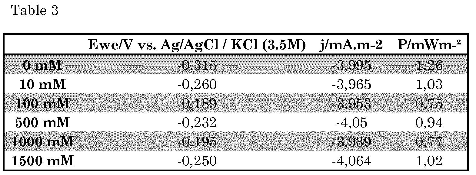
- Example 1 was repeated, this time using citric acid as a weak acid, in varying concentrations as illustrated in
figures 7 and 8 and in table 4 below. From table 4 it may be observed that the concentration of citric acid/citrate electrolyte did not affect substantially the power suministrated to the system for the electro synthesis reaction to take place. FromFig 8 it can be appreciated that, in contrast with experiments using phosphate as electrolyte (example 3), with citrate H2O2 mole production did not vary substantially when citrate concentration increases from 100 mM to 500 mM, or even increased (making the process less favourable).
- In
figure 9 the results obtained in terms of moles of H2O2 "produced after 4h of experiments in example 3 are compared with those obtained in example 4, making evident the beneficial effect of using HKH2PO4 as weak protonic electrolyte. -
Figure 10 shows the evolution of the pH of the catholyte with time, for varying concentrations of citric acid as weak protonic electrolyte. -
Figure 11 shows the evolution of the pH of the catholyte with time, for varying concentrations of HKH2PO4 as weak protonic electrolyte. -
- Alvarez-Gallego, Y., Dominguez-Benetton, X., Pant, D., Diels, L., Vanbroekhoven, K., Genné, I. & Vermeiren, P. (2012). Development of gas diffusion electrodes for cogeneration of chemicals and electricity. Electrochimica Acta .
- Dominguez-Benneton, X., Sveda, S., Vanbroekhoven, K. & Pant, D. (2012). The accurate use of impedance analysis for the study of microbial electrochemical systems. Chemical Society Reviews, 41 (21), 7228-7246.
- Edwards, K. (2009). Switching Off Hydrogen Peroxide Hydrogenation in the Direct Synthesis Process. Science, 323 (5917), 1037-1041
- Forti, J. C., Nunes, J. A., Lanza, M. R. V., & Bertazzoli, R. (2007). Azobenzene-modified oxygen-fed graphite/PTFE electrodes for hydrogen peroxide synthesis. Journal of applied electrochemistry, 37(4), 527-532.
- Forti, J. C., Rocha, R. S., Lanza, M. R. V., & Bertazzoli, R. (2007). Electrochemical synthesis of hydrogen peroxide on oxygen-fed graphite/PTFE electrodes modified by 2-ethylanthraquinone. Journal of Electroanalytical Chemistry, 601(1), 63-67.
- Giomo, M., Buso, A., Fier, P., Sandonà, G., Boye, B., & Farnia, G. (2008). A small-scale pilot plant using an oxygen-reducing gas-diffusion electrode for hydrogen peroxide electrosynthesis. Electrochimica Acta, 54(2), 808-815.
-
Harris, C. R. (1949). U.S. Patent No. 2,479,111 . Washington, DC: US Patent and Trademark Office. - Hoelderich, W. F. (2000). Environmentally benign manufacturing of fine and intermediate chemicals, Catalysis today, 62 (1), 115-130.
- Ntainjua, E. N., Piccinini, M., Prichard, J. C., Edwards, J. K., Carley, A. F., Kiely, C. J., & Hutchings, G. J. (2011). Direct synthesis of hydrogen peroxide using ceria-supported gold and palladium catalysts. Catalysis Today, 178(1), 47-50. doi: 10.1016/j.cattod.2011.06.024
-
Rust, F. F. (1955). US Patent No. 2,717,264 . Washington, DC: US Patent and Trademark Office. - Schlummer, B. & Scholz, U. (2004). Palladium, Catalyzed C, N, and C, O Coupling-A Practical Guide from an Industrial Vantage Point. Advanced Synthesis & Catalysis, 346 (13, 15), 1599-1626.
- Samanta, C. (2008). Direct synthesis of hydrogen peroxide from hydrogen and oxygen: An overview of recent developments in the process. Applied Catalysis A: General, 350(2), 133-149.
- Vulpescu, G. D., Ruitenbeek, M., van Lieshout, L. L. Correia, L. A., Meyer, D., & Pex, P. (2004). One-step selective oxidation over a Pd-based catalytic membrane; evaluation of the oxidation of benzene to phenol as a model reaction. Catalysis Communications, 5(6), 347-351. doi: 10.1016/1.catcom.2004.04.002
- Yamanaka, I., Onisawa, T., Hashimoto, T., & Murayama, T. (2011). A Fuel, Cell Reactor for the Direct Synthesis of Hydrogen Peroxide Alkaline Solutions from H2 and O2, ChemSusChem, 4(4), 494-501.
Claims (13)
- A method for producing hydrogen peroxide in an aqueous solution by electrochemical reduction of oxygen, wherein an oxygen containing gas is supplied to an electrochemically active side of a cathode contained in the cathodic compartment, wherein the cathode comprises a porous gas diffusion electrode one side of which comprises a carbon based electrochemically active layer capable of catalyzing the reduction of oxygen to hydrogen peroxide, the cathodic compartment being in fluid communication with an anodic compartment, characterized in that at least one at least partly water soluble, weak protonic electrolyte is supplied to the catholyte, wherein the weak protonic electrolyte has a pKa which is at least one unit higher than the pH of the catholyte at the onset of the oxygen reduction reaction to hydrogen peroxide, wherein the catholyte is not pH buffered and the pH of the catholyte is let to evolve in the course of the reaction.
- A method as claimed in claim 1, wherein the pKa of the weak protonic electrolyte is at least 1.25 units higher than the pH of the catholyte, preferably at least 1.50 units higher, more preferably at least 2.0 units higher than the pH of the catholyte at the onset of the oxygen reduction reaction.
- A method as claimed in claim 1 or 2, wherein the weak protonic electrolyte is a weak protonic acid having a pKa in the range of 2.0 ≤ pKa ≤8.0 or a weak protonic base having a pKa of between 6.0 ≤ pKa ≤ 12.0.
- A method as claimed in any one of claims 1-3, wherein the pH of the catholyte at the onset of the oxygen reduction reaction is at least 2.5 and the weak protonic electrolyte has a pKa of at least 3.5.
- A method as claimed in any of the previous claims, wherein the weak protonic acid is selected from the group of weak organic and weak inorganic acids, in particular acetic acid, citric acid, oxalic acid, lactic acid, gluconic acid, ascorbic acid, formic acid, glycolic acid, potassium monohydrogen phosphate, potassium dihydrogen phosphate, ammonium chloride, boric acid, sodium hydrogen sulphate, sodium hydrogen carbonate, ammonium chloride, and mixtures of two or more hereof.
- A method as claimed in any one of claims 1-4, wherein the weak protonic base has a pKa of between 7.0 and 11.0.
- A method as claimed in claim 6, wherein the weak protonic base is selected from the group of ammonia, trimethylammonia, ammoniumhydroxide, pyridine, the conjugated bases of acetic acid, citric acid, oxalic acid, lactic acid, gluconic acid, ascorbic acid, formic acid, glycolic acid, potassium monohydrogen phosphate, potassium dihydrogen phosphate, ammonium chloride, boric acid, sodium hydrogen sulphate, sodium hydrogen carbonate, or a mixture of two or more of the afore mentioned compounds.
- A method as claimed in any of claims 1 to 7, wherein the oxygen containing gas is selected from the group of air, pure oxygen, a mixture of oxygen with one or more inert gases for example N2, Ar, He, or a mixture of two or more of the afore mentioned gases.
- A method according to any one of claims 1-8, wherein the electrochemically active layer comprises electrically conductive carbonaceous particles with a catalytically active surface comprising protonic acidic functional groups.
- A method according to any one of claims 1 to 9, wherein the method is operated in a continuous process, and the weak protonic electrolyte is supplied with a constant flow rate or the flow rate of the weak protonic electrolyte is variable.
- A method according to any of the previous claims, wherein convective mass transfer is created in the catholyte and preferably also in the anolyte.
- A method as claimed in any of the claims 1-11, wherein the side of the electrochemically active layer of the gas diffusion electrode facing the gas phase, is coated with a layer of a hydrophobic material which is permeable to oxygen, preferably a hydrophobic material selected from the group of polyvinyldifluoride (PVDF), polytetrafluoroethylene (PTFE or Teflon), PSU.
- A method as claimed in any of claims 1-12, wherein the at least one anodic compartment and the at least one cathodic compartment are separated from each other by means of an ion permeable membrane, preferably a cation permeable membrane.
Applications Claiming Priority (2)
| Application Number | Priority Date | Filing Date | Title |
|---|---|---|---|
| EP14179927 | 2014-08-05 | ||
| PCT/EP2015/068091 WO2016020453A1 (en) | 2014-08-05 | 2015-08-05 | A device and method for the production of hydrogen peroxide |
Publications (2)
| Publication Number | Publication Date |
|---|---|
| EP3177754A1 EP3177754A1 (en) | 2017-06-14 |
| EP3177754B1 true EP3177754B1 (en) | 2018-10-03 |
Family
ID=51263334
Family Applications (1)
| Application Number | Title | Priority Date | Filing Date |
|---|---|---|---|
| EP15750326.9A Not-in-force EP3177754B1 (en) | 2014-08-05 | 2015-08-05 | Method for the production of hydrogen peroxide |
Country Status (3)
| Country | Link |
|---|---|
| US (1) | US20170226647A1 (en) |
| EP (1) | EP3177754B1 (en) |
| WO (1) | WO2016020453A1 (en) |
Families Citing this family (18)
| Publication number | Priority date | Publication date | Assignee | Title |
|---|---|---|---|---|
| JP6811444B2 (en) * | 2016-02-16 | 2021-01-13 | パナソニックIpマネジメント株式会社 | Electrochemical hydrogen pump |
| US10948451B2 (en) | 2017-06-15 | 2021-03-16 | Ramot At Tel-Aviv University Ltd. | Electrochemical detection of nitro-containing compounds |
| BR112019026721A2 (en) * | 2017-06-15 | 2020-06-30 | Ramot At Tel-Aviv University Ltd. | electrochemical detection of compounds containing peroxide |
| CN107317040A (en) * | 2017-06-22 | 2017-11-03 | 清华大学 | The floatation type gas-diffusion electrode reacted for gas consumption and its preparation |
| WO2019068488A1 (en) * | 2017-10-03 | 2019-04-11 | Vito Nv | Carbon based electrode with large geometric dimensions |
| WO2019118898A1 (en) * | 2017-12-15 | 2019-06-20 | The Board Of Trustees Of The Leland Stanford Junior University | High-efficiency oxygen reduction to hydrogen peroxide catalyzed by oxidized carbon materials |
| CN108101164A (en) * | 2018-01-08 | 2018-06-01 | 山西华鑫煤焦化实业集团有限公司 | A kind of three dimensional particles electrode for being applied to electro-Fenton reaction in situ and preparation method thereof |
| ES2858698T3 (en) * | 2018-06-05 | 2021-09-30 | Vito Nv | Carbon-based electrode with large geometric dimensions |
| DE102020103632A1 (en) * | 2020-02-12 | 2021-08-12 | Miele & Cie. Kg | Use of a component as an electrolyte for an electrochemical cell, method for operating a water-bearing electrical device and water-bearing electrical device |
| WO2021211852A1 (en) * | 2020-04-15 | 2021-10-21 | The Regents Of The University Of California | Electrocatalysts for h2o2 production |
| CN111380828A (en) * | 2020-04-28 | 2020-07-07 | 今麦郎饮品股份有限公司 | Method for detecting residual quantity of hydrogen peroxide in water |
| CN112760675A (en) * | 2020-12-22 | 2021-05-07 | 哈尔滨工业大学 | Method for electrosynthesis of hydrogen peroxide by using active coke-based gas diffusion electrode |
| CN114561652B (en) * | 2022-03-04 | 2023-05-02 | 安徽理工大学 | Membrane-process-free electrolytic water hydrogen production-reductive wastewater degradation coupling device and technology |
| CN114774978B (en) * | 2022-05-10 | 2024-04-09 | 浙江工业大学 | Ni-Fe MMO film modified foam nickel catalyst and preparation method and application thereof |
| CN114990610B (en) * | 2022-07-13 | 2023-06-13 | 郑州大学 | Method for preparing functionalized carbon material by in-situ oxidation, prepared carbon material and application thereof |
| CN116005179B (en) * | 2023-01-03 | 2025-04-01 | 万华化学集团股份有限公司 | A method for preparing FCAA by electrochemical in-situ oxidation of FCA |
| CN116043245B (en) * | 2023-02-27 | 2025-02-07 | 东华大学 | A method for preparing 1-aminoanthraquinone by electrocatalytic hydrogenation |
| CN119898860B (en) * | 2025-03-14 | 2026-01-06 | 广东工业大学 | A system and method for controlling the reduction of halogenated byproducts |
Family Cites Families (4)
| Publication number | Priority date | Publication date | Assignee | Title |
|---|---|---|---|---|
| US5112702A (en) * | 1990-03-19 | 1992-05-12 | E. I. Du Pont De Nemours And Company | Electrochemical synthesis of H2 O2 |
| GB9225421D0 (en) * | 1992-12-04 | 1993-01-27 | Chemetics Int | Electrolytic production of hydrogen peroxide using bipolar membranes |
| CA2378601A1 (en) * | 1999-08-05 | 2001-02-15 | Steris Inc. | Electrolytic synthesis of peracetic acid |
| US7754064B2 (en) * | 2006-09-29 | 2010-07-13 | Eltron Research & Development | Methods and apparatus for the on-site production of hydrogen peroxide |
-
2015
- 2015-08-05 WO PCT/EP2015/068091 patent/WO2016020453A1/en not_active Ceased
- 2015-08-05 EP EP15750326.9A patent/EP3177754B1/en not_active Not-in-force
- 2015-08-05 US US15/501,775 patent/US20170226647A1/en not_active Abandoned
Non-Patent Citations (1)
| Title |
|---|
| None * |
Also Published As
| Publication number | Publication date |
|---|---|
| US20170226647A1 (en) | 2017-08-10 |
| EP3177754A1 (en) | 2017-06-14 |
| WO2016020453A1 (en) | 2016-02-11 |
Similar Documents
| Publication | Publication Date | Title |
|---|---|---|
| EP3177754B1 (en) | Method for the production of hydrogen peroxide | |
| Tong et al. | Electrocatalytic oxygen reduction to produce hydrogen peroxide: rational design from single-atom catalysts to devices | |
| AU2020313943B2 (en) | A method for eficient electrocatalytic synthesis of pure liquid procuct solutions including H2O2, oxygenates, ammonia, and so on | |
| US11519082B2 (en) | Organic hydride production apparatus and method for producing organic hydride | |
| US4752364A (en) | Method for treating organic waste material and a catalyst/cocatalyst composition useful therefor | |
| US4699700A (en) | Method for hydrogen production and metal winning, and a catalyst/cocatalyst composition useful therefor | |
| EP2064367B1 (en) | Electrolysis cell for hydrogen peroxide production and method of use | |
| JP2000104189A (en) | Production of hydrogen peroxide and electrolytic cell for production | |
| CN104662203A (en) | Electrolysis cell of alkali solutions | |
| GB2028371A (en) | Electrolysis of aqueous alkali metal halides in a cell having catalytic electrodes bondes to the surface of a porous hydraulically permeable membrane/ separator | |
| US20230235465A1 (en) | Method for Electrochemical Production of a Product in a Cell Comprising a Polyelectrolyte | |
| AU2018232301B2 (en) | Electrodes comprising metal introduced into a solid-state electrolyte | |
| CN114481177A (en) | Reaction device for electrochemically preparing hydrogen peroxide by combining gas diffusion electrode with microchannel and application thereof | |
| Zhang et al. | Membrane electrode assembly for hydrogen peroxide electrosynthesis | |
| US20040053098A1 (en) | Electrochemical cell | |
| Theußl et al. | Technological advances in the electroreduction of CO2 to HCOOH: the impact of catalyst, gas diffusion electrode, and cell design | |
| JP2021138994A (en) | Electrode catalyst for reducing co2, method of producing electrode catalyst for reducing co2, co2 reducing electrode, and co2 reducing system | |
| Agladze et al. | DMFC with hydrogen peroxide cogeneration | |
| Löwe | Development and investigation of an efficient electrolysis process for the conversion of carbon dioxide to formate | |
| KR20240049164A (en) | Electrolysis apparatus and method of opreating the same | |
| Wan et al. | CO2 Electrochemical Reduction to CO: From Catalysts, Electrodes to Electrolytic Cells and Effect of Operating Conditions | |
| CA1152451A (en) | Electrolytic membrane and electrode structure including reduced platinum group metal oxide | |
| CN120153133A (en) | Electrolysis system and electrolysis method | |
| JP2025126596A (en) | Reaction device and method of producing chemical compound using the same | |
| Kveselava et al. | PROOF COPY [JES-10-0547R] 036009JES |
Legal Events
| Date | Code | Title | Description |
|---|---|---|---|
| STAA | Information on the status of an ep patent application or granted ep patent |
Free format text: STATUS: THE INTERNATIONAL PUBLICATION HAS BEEN MADE |
|
| PUAI | Public reference made under article 153(3) epc to a published international application that has entered the european phase |
Free format text: ORIGINAL CODE: 0009012 |
|
| STAA | Information on the status of an ep patent application or granted ep patent |
Free format text: STATUS: REQUEST FOR EXAMINATION WAS MADE |
|
| 17P | Request for examination filed |
Effective date: 20170220 |
|
| AK | Designated contracting states |
Kind code of ref document: A1 Designated state(s): AL AT BE BG CH CY CZ DE DK EE ES FI FR GB GR HR HU IE IS IT LI LT LU LV MC MK MT NL NO PL PT RO RS SE SI SK SM TR |
|
| AX | Request for extension of the european patent |
Extension state: BA ME |
|
| DAV | Request for validation of the european patent (deleted) | ||
| DAX | Request for extension of the european patent (deleted) | ||
| GRAP | Despatch of communication of intention to grant a patent |
Free format text: ORIGINAL CODE: EPIDOSNIGR1 |
|
| STAA | Information on the status of an ep patent application or granted ep patent |
Free format text: STATUS: GRANT OF PATENT IS INTENDED |
|
| INTG | Intention to grant announced |
Effective date: 20180413 |
|
| GRAS | Grant fee paid |
Free format text: ORIGINAL CODE: EPIDOSNIGR3 |
|
| GRAA | (expected) grant |
Free format text: ORIGINAL CODE: 0009210 |
|
| STAA | Information on the status of an ep patent application or granted ep patent |
Free format text: STATUS: THE PATENT HAS BEEN GRANTED |
|
| AK | Designated contracting states |
Kind code of ref document: B1 Designated state(s): AL AT BE BG CH CY CZ DE DK EE ES FI FR GB GR HR HU IE IS IT LI LT LU LV MC MK MT NL NO PL PT RO RS SE SI SK SM TR |
|
| REG | Reference to a national code |
Ref country code: GB Ref legal event code: FG4D |
|
| REG | Reference to a national code |
Ref country code: CH Ref legal event code: EP Ref country code: AT Ref legal event code: REF Ref document number: 1048703 Country of ref document: AT Kind code of ref document: T Effective date: 20181015 |
|
| REG | Reference to a national code |
Ref country code: IE Ref legal event code: FG4D Ref country code: DE Ref legal event code: R096 Ref document number: 602015017526 Country of ref document: DE |
|
| REG | Reference to a national code |
Ref country code: NL Ref legal event code: FP |
|
| REG | Reference to a national code |
Ref country code: LT Ref legal event code: MG4D |
|
| REG | Reference to a national code |
Ref country code: AT Ref legal event code: MK05 Ref document number: 1048703 Country of ref document: AT Kind code of ref document: T Effective date: 20181003 |
|
| PG25 | Lapsed in a contracting state [announced via postgrant information from national office to epo] |
Ref country code: LT Free format text: LAPSE BECAUSE OF FAILURE TO SUBMIT A TRANSLATION OF THE DESCRIPTION OR TO PAY THE FEE WITHIN THE PRESCRIBED TIME-LIMIT Effective date: 20181003 Ref country code: FI Free format text: LAPSE BECAUSE OF FAILURE TO SUBMIT A TRANSLATION OF THE DESCRIPTION OR TO PAY THE FEE WITHIN THE PRESCRIBED TIME-LIMIT Effective date: 20181003 Ref country code: HR Free format text: LAPSE BECAUSE OF FAILURE TO SUBMIT A TRANSLATION OF THE DESCRIPTION OR TO PAY THE FEE WITHIN THE PRESCRIBED TIME-LIMIT Effective date: 20181003 Ref country code: PL Free format text: LAPSE BECAUSE OF FAILURE TO SUBMIT A TRANSLATION OF THE DESCRIPTION OR TO PAY THE FEE WITHIN THE PRESCRIBED TIME-LIMIT Effective date: 20181003 Ref country code: BG Free format text: LAPSE BECAUSE OF FAILURE TO SUBMIT A TRANSLATION OF THE DESCRIPTION OR TO PAY THE FEE WITHIN THE PRESCRIBED TIME-LIMIT Effective date: 20190103 Ref country code: LV Free format text: LAPSE BECAUSE OF FAILURE TO SUBMIT A TRANSLATION OF THE DESCRIPTION OR TO PAY THE FEE WITHIN THE PRESCRIBED TIME-LIMIT Effective date: 20181003 Ref country code: ES Free format text: LAPSE BECAUSE OF FAILURE TO SUBMIT A TRANSLATION OF THE DESCRIPTION OR TO PAY THE FEE WITHIN THE PRESCRIBED TIME-LIMIT Effective date: 20181003 Ref country code: AT Free format text: LAPSE BECAUSE OF FAILURE TO SUBMIT A TRANSLATION OF THE DESCRIPTION OR TO PAY THE FEE WITHIN THE PRESCRIBED TIME-LIMIT Effective date: 20181003 Ref country code: IS Free format text: LAPSE BECAUSE OF FAILURE TO SUBMIT A TRANSLATION OF THE DESCRIPTION OR TO PAY THE FEE WITHIN THE PRESCRIBED TIME-LIMIT Effective date: 20190203 Ref country code: CZ Free format text: LAPSE BECAUSE OF FAILURE TO SUBMIT A TRANSLATION OF THE DESCRIPTION OR TO PAY THE FEE WITHIN THE PRESCRIBED TIME-LIMIT Effective date: 20181003 Ref country code: NO Free format text: LAPSE BECAUSE OF FAILURE TO SUBMIT A TRANSLATION OF THE DESCRIPTION OR TO PAY THE FEE WITHIN THE PRESCRIBED TIME-LIMIT Effective date: 20190103 |
|
| PG25 | Lapsed in a contracting state [announced via postgrant information from national office to epo] |
Ref country code: GR Free format text: LAPSE BECAUSE OF FAILURE TO SUBMIT A TRANSLATION OF THE DESCRIPTION OR TO PAY THE FEE WITHIN THE PRESCRIBED TIME-LIMIT Effective date: 20190104 Ref country code: PT Free format text: LAPSE BECAUSE OF FAILURE TO SUBMIT A TRANSLATION OF THE DESCRIPTION OR TO PAY THE FEE WITHIN THE PRESCRIBED TIME-LIMIT Effective date: 20190203 Ref country code: SE Free format text: LAPSE BECAUSE OF FAILURE TO SUBMIT A TRANSLATION OF THE DESCRIPTION OR TO PAY THE FEE WITHIN THE PRESCRIBED TIME-LIMIT Effective date: 20181003 Ref country code: RS Free format text: LAPSE BECAUSE OF FAILURE TO SUBMIT A TRANSLATION OF THE DESCRIPTION OR TO PAY THE FEE WITHIN THE PRESCRIBED TIME-LIMIT Effective date: 20181003 Ref country code: AL Free format text: LAPSE BECAUSE OF FAILURE TO SUBMIT A TRANSLATION OF THE DESCRIPTION OR TO PAY THE FEE WITHIN THE PRESCRIBED TIME-LIMIT Effective date: 20181003 |
|
| REG | Reference to a national code |
Ref country code: DE Ref legal event code: R097 Ref document number: 602015017526 Country of ref document: DE |
|
| PG25 | Lapsed in a contracting state [announced via postgrant information from national office to epo] |
Ref country code: DK Free format text: LAPSE BECAUSE OF FAILURE TO SUBMIT A TRANSLATION OF THE DESCRIPTION OR TO PAY THE FEE WITHIN THE PRESCRIBED TIME-LIMIT Effective date: 20181003 |
|
| PLBE | No opposition filed within time limit |
Free format text: ORIGINAL CODE: 0009261 |
|
| STAA | Information on the status of an ep patent application or granted ep patent |
Free format text: STATUS: NO OPPOSITION FILED WITHIN TIME LIMIT |
|
| PG25 | Lapsed in a contracting state [announced via postgrant information from national office to epo] |
Ref country code: SK Free format text: LAPSE BECAUSE OF FAILURE TO SUBMIT A TRANSLATION OF THE DESCRIPTION OR TO PAY THE FEE WITHIN THE PRESCRIBED TIME-LIMIT Effective date: 20181003 Ref country code: SM Free format text: LAPSE BECAUSE OF FAILURE TO SUBMIT A TRANSLATION OF THE DESCRIPTION OR TO PAY THE FEE WITHIN THE PRESCRIBED TIME-LIMIT Effective date: 20181003 Ref country code: EE Free format text: LAPSE BECAUSE OF FAILURE TO SUBMIT A TRANSLATION OF THE DESCRIPTION OR TO PAY THE FEE WITHIN THE PRESCRIBED TIME-LIMIT Effective date: 20181003 Ref country code: RO Free format text: LAPSE BECAUSE OF FAILURE TO SUBMIT A TRANSLATION OF THE DESCRIPTION OR TO PAY THE FEE WITHIN THE PRESCRIBED TIME-LIMIT Effective date: 20181003 |
|
| PGFP | Annual fee paid to national office [announced via postgrant information from national office to epo] |
Ref country code: LU Payment date: 20190725 Year of fee payment: 5 Ref country code: NL Payment date: 20190726 Year of fee payment: 5 |
|
| 26N | No opposition filed |
Effective date: 20190704 |
|
| PG25 | Lapsed in a contracting state [announced via postgrant information from national office to epo] |
Ref country code: SI Free format text: LAPSE BECAUSE OF FAILURE TO SUBMIT A TRANSLATION OF THE DESCRIPTION OR TO PAY THE FEE WITHIN THE PRESCRIBED TIME-LIMIT Effective date: 20181003 |
|
| PGFP | Annual fee paid to national office [announced via postgrant information from national office to epo] |
Ref country code: DE Payment date: 20190722 Year of fee payment: 5 Ref country code: IT Payment date: 20190722 Year of fee payment: 5 Ref country code: FR Payment date: 20190723 Year of fee payment: 5 |
|
| PGFP | Annual fee paid to national office [announced via postgrant information from national office to epo] |
Ref country code: BE Payment date: 20190725 Year of fee payment: 5 |
|
| PGFP | Annual fee paid to national office [announced via postgrant information from national office to epo] |
Ref country code: GB Payment date: 20190722 Year of fee payment: 5 |
|
| PG25 | Lapsed in a contracting state [announced via postgrant information from national office to epo] |
Ref country code: TR Free format text: LAPSE BECAUSE OF FAILURE TO SUBMIT A TRANSLATION OF THE DESCRIPTION OR TO PAY THE FEE WITHIN THE PRESCRIBED TIME-LIMIT Effective date: 20181003 |
|
| PG25 | Lapsed in a contracting state [announced via postgrant information from national office to epo] |
Ref country code: MC Free format text: LAPSE BECAUSE OF FAILURE TO SUBMIT A TRANSLATION OF THE DESCRIPTION OR TO PAY THE FEE WITHIN THE PRESCRIBED TIME-LIMIT Effective date: 20181003 Ref country code: LI Free format text: LAPSE BECAUSE OF NON-PAYMENT OF DUE FEES Effective date: 20190831 Ref country code: CH Free format text: LAPSE BECAUSE OF NON-PAYMENT OF DUE FEES Effective date: 20190831 |
|
| PG25 | Lapsed in a contracting state [announced via postgrant information from national office to epo] |
Ref country code: IE Free format text: LAPSE BECAUSE OF NON-PAYMENT OF DUE FEES Effective date: 20190805 |
|
| REG | Reference to a national code |
Ref country code: DE Ref legal event code: R119 Ref document number: 602015017526 Country of ref document: DE |
|
| REG | Reference to a national code |
Ref country code: NL Ref legal event code: MM Effective date: 20200901 |
|
| GBPC | Gb: european patent ceased through non-payment of renewal fee |
Effective date: 20200805 |
|
| PG25 | Lapsed in a contracting state [announced via postgrant information from national office to epo] |
Ref country code: LU Free format text: LAPSE BECAUSE OF NON-PAYMENT OF DUE FEES Effective date: 20200805 |
|
| REG | Reference to a national code |
Ref country code: BE Ref legal event code: MM Effective date: 20200831 |
|
| PG25 | Lapsed in a contracting state [announced via postgrant information from national office to epo] |
Ref country code: CY Free format text: LAPSE BECAUSE OF FAILURE TO SUBMIT A TRANSLATION OF THE DESCRIPTION OR TO PAY THE FEE WITHIN THE PRESCRIBED TIME-LIMIT Effective date: 20181003 |
|
| PG25 | Lapsed in a contracting state [announced via postgrant information from national office to epo] |
Ref country code: HU Free format text: LAPSE BECAUSE OF FAILURE TO SUBMIT A TRANSLATION OF THE DESCRIPTION OR TO PAY THE FEE WITHIN THE PRESCRIBED TIME-LIMIT; INVALID AB INITIO Effective date: 20150805 Ref country code: MT Free format text: LAPSE BECAUSE OF FAILURE TO SUBMIT A TRANSLATION OF THE DESCRIPTION OR TO PAY THE FEE WITHIN THE PRESCRIBED TIME-LIMIT Effective date: 20181003 Ref country code: DE Free format text: LAPSE BECAUSE OF NON-PAYMENT OF DUE FEES Effective date: 20210302 Ref country code: FR Free format text: LAPSE BECAUSE OF NON-PAYMENT OF DUE FEES Effective date: 20200831 Ref country code: IT Free format text: LAPSE BECAUSE OF NON-PAYMENT OF DUE FEES Effective date: 20200805 |
|
| PG25 | Lapsed in a contracting state [announced via postgrant information from national office to epo] |
Ref country code: BE Free format text: LAPSE BECAUSE OF NON-PAYMENT OF DUE FEES Effective date: 20200831 Ref country code: GB Free format text: LAPSE BECAUSE OF NON-PAYMENT OF DUE FEES Effective date: 20200805 |
|
| PG25 | Lapsed in a contracting state [announced via postgrant information from national office to epo] |
Ref country code: NL Free format text: LAPSE BECAUSE OF NON-PAYMENT OF DUE FEES Effective date: 20200901 |
|
| PG25 | Lapsed in a contracting state [announced via postgrant information from national office to epo] |
Ref country code: MK Free format text: LAPSE BECAUSE OF FAILURE TO SUBMIT A TRANSLATION OF THE DESCRIPTION OR TO PAY THE FEE WITHIN THE PRESCRIBED TIME-LIMIT Effective date: 20181003 |