EP3177131B1 - Forward support rotating assembly for a snapping roll of a snapping unit of a combine harvesting machine - Google Patents
Forward support rotating assembly for a snapping roll of a snapping unit of a combine harvesting machine Download PDFInfo
- Publication number
- EP3177131B1 EP3177131B1 EP15767299.9A EP15767299A EP3177131B1 EP 3177131 B1 EP3177131 B1 EP 3177131B1 EP 15767299 A EP15767299 A EP 15767299A EP 3177131 B1 EP3177131 B1 EP 3177131B1
- Authority
- EP
- European Patent Office
- Prior art keywords
- snapping
- seat
- snapping roll
- annular
- roll according
- Prior art date
- Legal status (The legal status is an assumption and is not a legal conclusion. Google has not performed a legal analysis and makes no representation as to the accuracy of the status listed.)
- Active
Links
- 238000003306 harvesting Methods 0.000 title claims description 9
- 238000012856 packing Methods 0.000 claims description 18
- OKTJSMMVPCPJKN-UHFFFAOYSA-N Carbon Chemical compound [C] OKTJSMMVPCPJKN-UHFFFAOYSA-N 0.000 claims description 4
- 239000000835 fiber Substances 0.000 claims description 4
- 239000000314 lubricant Substances 0.000 claims description 4
- 239000000463 material Substances 0.000 claims description 4
- 238000007789 sealing Methods 0.000 claims description 4
- 244000025254 Cannabis sativa Species 0.000 claims description 2
- 235000012766 Cannabis sativa ssp. sativa var. sativa Nutrition 0.000 claims description 2
- 235000012765 Cannabis sativa ssp. sativa var. spontanea Nutrition 0.000 claims description 2
- 229910000975 Carbon steel Inorganic materials 0.000 claims description 2
- 229920000742 Cotton Polymers 0.000 claims description 2
- 229920000271 Kevlar® Polymers 0.000 claims description 2
- 239000004809 Teflon Substances 0.000 claims description 2
- 229920006362 Teflon® Polymers 0.000 claims description 2
- 239000011230 binding agent Substances 0.000 claims description 2
- 235000009120 camo Nutrition 0.000 claims description 2
- 239000010962 carbon steel Substances 0.000 claims description 2
- 235000005607 chanvre indien Nutrition 0.000 claims description 2
- 230000007797 corrosion Effects 0.000 claims description 2
- 238000005260 corrosion Methods 0.000 claims description 2
- 229910002804 graphite Inorganic materials 0.000 claims description 2
- 239000010439 graphite Substances 0.000 claims description 2
- 239000011487 hemp Substances 0.000 claims description 2
- 239000003112 inhibitor Substances 0.000 claims description 2
- 239000004761 kevlar Substances 0.000 claims description 2
- 229920001343 polytetrafluoroethylene Polymers 0.000 claims description 2
- 239000004810 polytetrafluoroethylene Substances 0.000 claims description 2
- 239000003760 tallow Substances 0.000 claims description 2
- 230000000712 assembly Effects 0.000 description 4
- 238000000429 assembly Methods 0.000 description 4
- 238000012423 maintenance Methods 0.000 description 4
- 235000013339 cereals Nutrition 0.000 description 2
- 238000005265 energy consumption Methods 0.000 description 2
- 238000005461 lubrication Methods 0.000 description 2
- 241000196324 Embryophyta Species 0.000 description 1
- 239000003638 chemical reducing agent Substances 0.000 description 1
- 230000000694 effects Effects 0.000 description 1
- 210000004907 gland Anatomy 0.000 description 1
- 230000001050 lubricating effect Effects 0.000 description 1
- 238000004519 manufacturing process Methods 0.000 description 1
- 229920003052 natural elastomer Polymers 0.000 description 1
- 229920001194 natural rubber Polymers 0.000 description 1
- 238000013021 overheating Methods 0.000 description 1
- 239000007787 solid Substances 0.000 description 1
- 229920003051 synthetic elastomer Polymers 0.000 description 1
- 239000005061 synthetic rubber Substances 0.000 description 1
- 239000002699 waste material Substances 0.000 description 1
Images


Classifications
-
- A—HUMAN NECESSITIES
- A01—AGRICULTURE; FORESTRY; ANIMAL HUSBANDRY; HUNTING; TRAPPING; FISHING
- A01D—HARVESTING; MOWING
- A01D45/00—Harvesting of standing crops
- A01D45/02—Harvesting of standing crops of maize, i.e. kernel harvesting
- A01D45/021—Cornheaders
- A01D45/025—Snapping rolls
-
- A—HUMAN NECESSITIES
- A01—AGRICULTURE; FORESTRY; ANIMAL HUSBANDRY; HUNTING; TRAPPING; FISHING
- A01D—HARVESTING; MOWING
- A01D41/00—Combines, i.e. harvesters or mowers combined with threshing devices
- A01D41/12—Details of combines
-
- A—HUMAN NECESSITIES
- A01—AGRICULTURE; FORESTRY; ANIMAL HUSBANDRY; HUNTING; TRAPPING; FISHING
- A01D—HARVESTING; MOWING
- A01D45/00—Harvesting of standing crops
- A01D45/02—Harvesting of standing crops of maize, i.e. kernel harvesting
Definitions
- the invention relates to a forward support rotating assembly for a snapping roll of a snapping unit of a combine harvesting machine.
- Combine harvesting machines for cereals are equipped with a head which is arranged in the front part of the machine and includes a set of snapping units.
- the snapping units are intended for pulling the stalks of the cereal plants downwards, until causing the detachment of the cobs while the machine is moving forward.
- Each snapping unit comprises a support and motion transmitting unit, to which two counter-rotating snapping rolls are cinematically associated.
- the support and motion transmitting unit is generally equipped with a motor-reducer, to bring the snapping rolls into rotation.
- the snapping rolls are rotatably supported by the support and motion transmitting unit at their rear ends only, i.e. in cantilevered manner, or they are supported at both ends, i.e. at their front and rear ends.
- the snapping rolls comprise a substantially cylindrical body with a tapered, generally frustoconical front end portion, defining a draft region for making the entry of the stalks between the counter-rotating rolls easier.
- the side surface of each roll is provided with protruding portions, which give rise to the downward-pulling effect on the stalks by cooperating with the protruding portions of the adjacent roll in the same snapping unit.
- EP 1502492 and US 7237373 disclose examples of snapping units equipped with helical side protrusions and with protrusions shaped as longitudinal radial knives, respectively.
- the radial protrusions and the knives may be rectilinear and extend substantially along a generatrix of the cylindrical body, or they may be elliptical, continuous or interrupted, integrally formed in the roll body or removable in order to allow their replacement.
- the snapping rolls are to be rotatably associated to the support and motion transmitting unit of the snapping unit.
- US-A-2718821 discloses a forward support rotating assembly for a snapping roll with a frontally open axial seat, a cylindrical support pin with a support bracket, a sliding element between the support pin and the seat and a seal element.
- GB-A-2007777 and FR 2596484 disclose respective radial-shaft sealing arrangements comprising labyrinth seal elements.
- a not least object of the invention is to provide an assembly of the aforementioned kind that can be made industrially and with limited costs and requires lower energy consumption for being brought into rotation.
- the forward support rotating assembly for a snapping roll comprises an axial seat provided in the snapping roll.
- a cylindrical body, preferably solid, defining a support pin of the support assembly is received in the axial seat.
- the support pin extends axially in the seat of the snapping roll.
- the seat is frontally open and is provided with an inner circumferential abutment edge provided in a distal position with respect to the front opening of the seat.
- the abutment edge defines a support base for the components of the support assembly received in the axial seat.
- At least one sliding element and at least one labyrinth seal element are interposed between the support pin and the inner wall of the seat. The labyrinth seal element frontally closes the seat toward the outside, thus isolating the sliding element from the environment outside the snapping roll.
- an elastic ring for locking the sliding element and an elastic annular seal are preferably also provided.
- the sliding element comprises a ball bearing.
- the locking ring comprises a Seeger ring housed in a radial annular slot formed in the inner wall of the seat.
- the elastic annular seal is preferably a suitably shaped elastic ring made of a natural or synthetic rubber.
- the labyrinth seal element comprises a cylindrical gland having a labyrinth cross-section, in which there are defined an inner annular seat and an annular packing seal received in the annular seat and radially contacting the outer surface of the cylindrical support pin. The packing seal is received in the space between the outer surface of the cylindrical body and the inner wall of the seat.
- the packing seal preferably comprises a fiber, a binder and a lubricant.
- the packing seal comprises an elastic braid made of cotton and full of tallow.
- the packing seal is made of a weft of yarns made of a single material or different materials, braids or strands of hemp, soaked with fat in order to ensure tight-sealing and friction resistance thereof.
- the packing seal is made of fibers of teflon (or PTFE), kevlar and graphite.
- the elastic annular seal comprises a double-lip gasket having a U-shaped cross-section in which there are defined an outer annular portion, an inner annular portion having a double lip extending radially toward the inside, and a transverse connecting portion between the outer portion and the inner portion.
- the double lip comprises two corresponding elastic flaps radially diverging at an angle comprised between 60° and 120°, preferably at 90°.
- the cylindrical ferrule has a substantially F-shaped cross-section in which there is defined an outer annular portion and two parallel inner radial portions between which the slot for the packing seal is defined.
- the support rotating assembly 11 of a snapping roll 13 comprises an axial seat 15 in the roll 13.
- the seat 15 is frontally open and has an inner circumferential abutment edge 17.
- the seat 15 is frontally arranged in the roll 13.
- the support assembly 11 further comprises a cylindrical support pin 19 extending axially in the seat 15.
- the pin 19 is integral to a support bracket 21 for fixing the assembly 11 to a snapping unit 23 of a combine harvesting machine.
- the support assembly 11 comprises a sliding element 25 interposed between the support pin 19 and the seat 15.
- the sliding element 25 is a ball bearing.
- the outer ring 25a of the bearing 25 is radially in contact with the inner wall 27 of the seat 15.
- the inner ring 25b of the bearing 25 is radially in contact with the outer wall 29 of the pin 19.
- the bearing 25 is further axially in contact with the abutment edge 17 of the seat 15.
- a radial annular slot 31 housing an elastic ring 33 for locking the sliding element 25 is formed in the wall 27.
- the elastic ring 33 consists of a Seeger ring.
- An elastic annular seal 35 is provided between the support pin 19 and the inner wall 27 of the seat 15.
- the seal 35 consists of a double-lip gasket having a substantially U-shaped cross-section.
- an outer annular portion 35a, an inner annular portion 35b having a double lip 35c,35d and extending radially toward the inside, and a transverse connecting portion 35e arranged between the outer portion 35a and the inner portion 35b are defined in the seal 35.
- the double lip comprises two corresponding elastic flaps 35c,35d, radially diverging and forming between them an angle comprised between 60° and 120°, preferably an angle of 90°.
- the seal 35 is further axially in contact with the elastic ring 33.
- the support assembly 11 is further provided with a labyrinth seal element 37.
- the labyrinth seal element 37 comprises a cylindrical ferrule 39 and an annular packing seal 41.
- the ferrule 39 has a labyrinth cross-section in which an inner annular groove 39a housing the packing seal 41 is defined.
- the packing seal 41 is radially in contact with the outer surface 29 of the support pin 19.
- the cylindrical ferrule 39 has a substantially F-shaped cross-section in which there is defined an outer annular portion 39b and two parallel inner radial portions 39c,39d between which the groove 39a for the packing 41 is defined.
- the cylindrical ferrule 39 is made of carbon steel.
- the packing seal 41 comprises for instance a braid of synthetic yarn impregnated with graphite powder, a corrosion inhibitor and a lubricant.
- the assembly 11 according to the invention is substantially maintenance-free, i.e.
- the snapping roll 13 comprises a helical surface 51 at its front end supported by the support assembly 11.
- the snapping roll 13 extends longitudinally inside a support chamber 53 and is rotated by a support and motion transmitting unit 55.
- the snapping roll 13 is preferably hollow and further comprises a sealing plug 57 isolating the sliding element 25 from the chamber inside the roll 13, on the side opposite to the labyrinth seal 39.
- the snapping unit 23 will not be described further as it is part of the prior art known to the person skilled in the art.
- the invention is adapted to be applied to the industry of agricultural mechanics, namely to snapping units of either new produced or already existing combine harvesting machines. Indeed, it is advantageously possible to provide with the support rotating assembly also combine machines having conventional support assemblies.
Description
- The invention relates to a forward support rotating assembly for a snapping roll of a snapping unit of a combine harvesting machine.
- Combine harvesting machines for cereals are equipped with a head which is arranged in the front part of the machine and includes a set of snapping units. The snapping units are intended for pulling the stalks of the cereal plants downwards, until causing the detachment of the cobs while the machine is moving forward. Each snapping unit comprises a support and motion transmitting unit, to which two counter-rotating snapping rolls are cinematically associated. The support and motion transmitting unit is generally equipped with a motor-reducer, to bring the snapping rolls into rotation. Depending on the applications, the snapping rolls are rotatably supported by the support and motion transmitting unit at their rear ends only, i.e. in cantilevered manner, or they are supported at both ends, i.e. at their front and rear ends.
- The snapping rolls comprise a substantially cylindrical body with a tapered, generally frustoconical front end portion, defining a draft region for making the entry of the stalks between the counter-rotating rolls easier. The side surface of each roll is provided with protruding portions, which give rise to the downward-pulling effect on the stalks by cooperating with the protruding portions of the adjacent roll in the same snapping unit.
EP 1502492 andUS 7237373 disclose examples of snapping units equipped with helical side protrusions and with protrusions shaped as longitudinal radial knives, respectively. The radial protrusions and the knives may be rectilinear and extend substantially along a generatrix of the cylindrical body, or they may be elliptical, continuous or interrupted, integrally formed in the roll body or removable in order to allow their replacement. - As mentioned above, the snapping rolls are to be rotatably associated to the support and motion transmitting unit of the snapping unit.
-
US-A-2718821 discloses a forward support rotating assembly for a snapping roll with a frontally open axial seat, a cylindrical support pin with a support bracket, a sliding element between the support pin and the seat and a seal element. -
GB-A-2007777 FR 2596484 - At present support rotating assemblies requiring frequent lubrication are used. The need for frequent lubrication of the support assembly constitutes an important drawback. The snapping rolls, indeed, need to be manually lubricated while the machine is stopped, with the consequence of a remarkable waste of time and labor. Modern combine harvesting machines are indeed usually equipped with a plurality of snapping rolls and the step of lubricating the whole head can take remarkable time. In addition, the support assemblies currently used are not particularly reliable and robust and, even when they are subjected to regular maintenance interventions, they often cause a rise in the high energy consumption for rotating them as well as because of overheating, seizing and breaking.
- A first object of the invention is therefore to provide a forward support rotating assembly for a snapping roll of a snapping unit of a combine harvesting machine that has more dilated maintenance intervals than prior art assemblies. Another object of the invention is to provide an assembly of the aforementioned kind that requires substantially no maintenance. A further object of the invention is to provide a forward support rotating assembly for a snapping roll of snapping units of combine harvesting machines that is reliable and easy to manufacture. A not least object of the invention is to provide an assembly of the aforementioned kind that can be made industrially and with limited costs and requires lower energy consumption for being brought into rotation.
- These and other objects are achieved with the support rotating assembly according to the invention as claimed in the appended claims.
- The forward support rotating assembly for a snapping roll comprises an axial seat provided in the snapping roll. A cylindrical body, preferably solid, defining a support pin of the support assembly is received in the axial seat. The support pin extends axially in the seat of the snapping roll. The seat is frontally open and is provided with an inner circumferential abutment edge provided in a distal position with respect to the front opening of the seat. The abutment edge defines a support base for the components of the support assembly received in the axial seat. At least one sliding element and at least one labyrinth seal element are interposed between the support pin and the inner wall of the seat. The labyrinth seal element frontally closes the seat toward the outside, thus isolating the sliding element from the environment outside the snapping roll.
- In addition, an elastic ring for locking the sliding element and an elastic annular seal are preferably also provided. According to a preferred embodiment of the invention, the sliding element comprises a ball bearing. Still according to this embodiment, the locking ring comprises a Seeger ring housed in a radial annular slot formed in the inner wall of the seat. The elastic annular seal is preferably a suitably shaped elastic ring made of a natural or synthetic rubber. The labyrinth seal element comprises a cylindrical gland having a labyrinth cross-section, in which there are defined an inner annular seat and an annular packing seal received in the annular seat and radially contacting the outer surface of the cylindrical support pin. The packing seal is received in the space between the outer surface of the cylindrical body and the inner wall of the seat. The packing seal preferably comprises a fiber, a binder and a lubricant. In an embodiment of the invention, the packing seal comprises an elastic braid made of cotton and full of tallow. In other embodiments of the invention the packing seal is made of a weft of yarns made of a single material or different materials, braids or strands of hemp, soaked with fat in order to ensure tight-sealing and friction resistance thereof. In still other embodiments, the packing seal is made of fibers of teflon (or PTFE), kevlar and graphite. The elastic annular seal comprises a double-lip gasket having a U-shaped cross-section in which there are defined an outer annular portion, an inner annular portion having a double lip extending radially toward the inside, and a transverse connecting portion between the outer portion and the inner portion. The double lip comprises two corresponding elastic flaps radially diverging at an angle comprised between 60° and 120°, preferably at 90°. The cylindrical ferrule has a substantially F-shaped cross-section in which there is defined an outer annular portion and two parallel inner radial portions between which the slot for the packing seal is defined.
- Some preferred embodiments of the invention will be described below by way of non-limiting examples with reference to the annexed figures, in which:
-
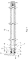
Fig.1 is a longitudinal section of a snapping roll provided with a forward support rotating assembly according to a preferred embodiment of the invention; -
Fig.2 is an enlarged view of the support assembly ofFig.1 ; -
Fig.3 is a top plan view of a snapping unit equipped with two snapping rolls provided with a support assembly according toFig. 1 . - Referring to
Figs. 1 to 3 , thesupport rotating assembly 11 of a snappingroll 13 comprises anaxial seat 15 in theroll 13. Theseat 15 is frontally open and has an innercircumferential abutment edge 17. Theseat 15 is frontally arranged in theroll 13. Thesupport assembly 11 further comprises acylindrical support pin 19 extending axially in theseat 15. Thepin 19 is integral to asupport bracket 21 for fixing theassembly 11 to a snappingunit 23 of a combine harvesting machine. Thesupport assembly 11 comprises a slidingelement 25 interposed between thesupport pin 19 and theseat 15. In the illustrated embodiment, the slidingelement 25 is a ball bearing. Theouter ring 25a of thebearing 25 is radially in contact with theinner wall 27 of theseat 15. Theinner ring 25b of thebearing 25 is radially in contact with theouter wall 29 of thepin 19. Thebearing 25 is further axially in contact with theabutment edge 17 of theseat 15. A radialannular slot 31 housing anelastic ring 33 for locking the slidingelement 25 is formed in thewall 27. In the illustrated embodiment, theelastic ring 33 consists of a Seeger ring. An elasticannular seal 35 is provided between thesupport pin 19 and theinner wall 27 of theseat 15. In the illustrated embodiment, theseal 35 consists of a double-lip gasket having a substantially U-shaped cross-section. An outer annular portion 35a, an innerannular portion 35b having adouble lip portion 35e arranged between the outer portion 35a and theinner portion 35b are defined in theseal 35. In the illustrated embodiment, the double lip comprises two correspondingelastic flaps seal 35 is further axially in contact with theelastic ring 33. According to the invention, thesupport assembly 11 is further provided with alabyrinth seal element 37. Thelabyrinth seal element 37 comprises acylindrical ferrule 39 and anannular packing seal 41. Theferrule 39 has a labyrinth cross-section in which an innerannular groove 39a housing the packingseal 41 is defined. The packingseal 41 is radially in contact with theouter surface 29 of thesupport pin 19. Thecylindrical ferrule 39 has a substantially F-shaped cross-section in which there is defined an outer annular portion 39b and two parallel innerradial portions groove 39a for the packing 41 is defined. According to a preferred embodiment of the invention thecylindrical ferrule 39 is made of carbon steel. The packingseal 41 comprises for instance a braid of synthetic yarn impregnated with graphite powder, a corrosion inhibitor and a lubricant. Theassembly 11 according to the invention is substantially maintenance-free, i.e. it does not require maintenance interventions, practically for the entire service life of the snappingroll 13. In the shown example, the snappingroll 13 comprises ahelical surface 51 at its front end supported by thesupport assembly 11. The snappingroll 13 extends longitudinally inside asupport chamber 53 and is rotated by a support andmotion transmitting unit 55. The snappingroll 13 is preferably hollow and further comprises a sealing plug 57 isolating the slidingelement 25 from the chamber inside theroll 13, on the side opposite to thelabyrinth seal 39. The snappingunit 23 will not be described further as it is part of the prior art known to the person skilled in the art. - The invention is adapted to be applied to the industry of agricultural mechanics, namely to snapping units of either new produced or already existing combine harvesting machines. Indeed, it is advantageously possible to provide with the support rotating assembly also combine machines having conventional support assemblies.
Claims (10)
- A snapping roll (13) of a snapping unit (23) of a combine harvesting machine, comprising a forward support rotating assembly (11) comprising:- a frontally open axial seat (15) provided in the snapping roll (13) and having an inner circumferential abutment edge (17);- a cylindrical support pin (19) extending axially in the seat (15) and being integral with a support bracket (21) for fixing the assembly (11) to a snapping unit (23);- a sliding element (25) interposed between the support pin (19) and the seat (15); - an elastic annular seal (35) between the cylindrical support pin (19) and the inner wall (27) of the eat (15);characterized in that said assembly further comprises:- a labyrinth seal element (37) comprising a cylindrical ferrule (39), having a labyrinth cross-section in which there is defined an inner annular seat (39a), and an annular packing seal (41), comprising a fiber, a binder and a lubricant, received in the annular seat (39a) and radially contacting the outer surface (29) of the cylindrical support pin (19), wherein the labyrinth seal element (37) frontally seals the seat (15) with respect to the outside, wherein said elastic annular seal (35) is axially located between said sliding element (25) and said cylindrical ferrule (39) and wherein the cylindrical ferrule (39) has a substantially F-shaped cross-section in which there is defined an outer annular portion (39b) and two parallel inner radial portions (39c,39d) between which the seat (39a) for the packing seal (41) is defined.
- Snapping roll according to claim 1, wherein the sliding element (25) is a ball bearing axially contacting the abutment edge (17).
- Snapping roll according to claim 2, comprising an elastic ring (33) adapted for locking the bearing (25) and housed in a radial annular slot (31) formed in the inner wall (27) of the seat (15) and wherein the bearing (25) axially contacts the elastic ring (33).
- Snapping roll according to claim 1 or 2 or 3, wherein the elastic annular seal (35) is a double-lip gasket having a U-shaped cross-section in which there are defined an outer annular portion (35a), an inner annular portion (35b) having a double lip (35c,35d) and extending radially toward the inside, and a transverse connecting portion (35e) between the outer portion (35a) and the inner portion (35b).
- Snapping roll according to claim 4, wherein the double lip comprises two corresponding elastic flaps (35c, 35d) radially diverging at an angle comprised between 60° and 120°.
- Snapping roll according to any of the preceding claims, wherein the cylindrical ferrule (39) is made of carbon steel.
- Snapping roll according to any of the preceding claims, wherein the packing seal (41) comprises a braid of synthetic yarn impregnated with graphite powder, a corrosion inhibitor and a lubricant.
- Snapping roll according to any claim from 1 to 6, wherein the packing seal (41) comprises an elastic braid made of cotton and full of tallow.
- Snapping roll according to any claim from 1 to 6, wherein the packing seal (41) is made of a weft of yarns made of a single material or different materials, braids or strands of hemp, soaked with fat in order to ensure tight-sealing and friction resistance thereof.
- Snapping roll according to any claim from 1 to 6, wherein the packing seal (41) is made of fibers of Teflon or PTFE, Kevlar and graphite.
Priority Applications (2)
| Application Number | Priority Date | Filing Date | Title |
|---|---|---|---|
| HUE15767299A HUE057408T2 (en) | 2014-08-04 | 2015-08-11 | Forward support rotating assembly for a snapping roll of a snapping unit of a combine harvesting machine |
| PL15767299T PL3177131T3 (en) | 2014-08-04 | 2015-08-11 | Forward support rotating assembly for a snapping roll of a snapping unit of a combine harvesting machine |
Applications Claiming Priority (2)
| Application Number | Priority Date | Filing Date | Title |
|---|---|---|---|
| ITTO20140627 | 2014-08-04 | ||
| PCT/IB2015/056116 WO2016020903A1 (en) | 2014-08-04 | 2015-08-11 | Forward support rotating assembly for a snapping roll of a snapping unit of a combine harvesting machine |
Publications (2)
| Publication Number | Publication Date |
|---|---|
| EP3177131A1 EP3177131A1 (en) | 2017-06-14 |
| EP3177131B1 true EP3177131B1 (en) | 2021-09-29 |
Family
ID=51663372
Family Applications (1)
| Application Number | Title | Priority Date | Filing Date |
|---|---|---|---|
| EP15767299.9A Active EP3177131B1 (en) | 2014-08-04 | 2015-08-11 | Forward support rotating assembly for a snapping roll of a snapping unit of a combine harvesting machine |
Country Status (10)
| Country | Link |
|---|---|
| US (1) | US10136580B2 (en) |
| EP (1) | EP3177131B1 (en) |
| CN (1) | CN106659120B (en) |
| BR (1) | BR112017002331B1 (en) |
| ES (1) | ES2902792T3 (en) |
| HU (1) | HUE057408T2 (en) |
| PL (1) | PL3177131T3 (en) |
| PT (1) | PT3177131T (en) |
| RU (1) | RU2689667C2 (en) |
| WO (1) | WO2016020903A1 (en) |
Families Citing this family (2)
| Publication number | Priority date | Publication date | Assignee | Title |
|---|---|---|---|---|
| IT201600131283A1 (en) | 2016-12-27 | 2018-06-27 | Capello S R L | Harvesting head for a cereal harvesting machine |
| US20180199510A1 (en) * | 2017-01-17 | 2018-07-19 | 360 Yield Center | Stalk roll shaft retention assembly |
Family Cites Families (32)
| Publication number | Priority date | Publication date | Assignee | Title |
|---|---|---|---|---|
| US1976705A (en) * | 1933-02-18 | 1934-10-09 | Blue Ridge Glass Corp | Apparatus for turning concave rolls |
| US2180594A (en) * | 1936-12-10 | 1939-11-21 | Kuhlman Mfg Company | Corn harvester |
| US2334945A (en) * | 1942-09-21 | 1943-11-23 | Int Harvester Co | Harvester |
| US2618113A (en) * | 1948-09-23 | 1952-11-18 | Int Harvester Co | Remote-control release of snapping rolls |
| US2708821A (en) * | 1951-05-31 | 1955-05-24 | Case Co J I | Self-aligning bearing for corn picker snapping roll |
| US2927414A (en) * | 1957-07-29 | 1960-03-08 | Deere & Co | Ear pick-up rollers for corn harvesters |
| FR79963E (en) | 1960-06-23 | 1963-02-22 | Braud Ets | Improvements to maize harvesting machines |
| SU144661A1 (en) * | 1961-04-17 | 1961-11-30 | В.В. Деревенко | Combine for harvesting corn |
| AT277633B (en) * | 1968-06-27 | 1969-12-29 | Epple Buxbaum Werke | Corn picking machine |
| BE795548A (en) * | 1972-02-16 | 1973-06-18 | Ciofi Mario | BOX FOR THE ACTUATION OF AN OSCILLATING COMB FROM A CARDING SYSTEM |
| CA960471A (en) * | 1972-03-20 | 1975-01-07 | Arved Maiste | Drive mechanism for corn header gathering unit |
| IT1016411B (en) | 1973-08-03 | 1977-05-30 | Freudenberg C | IMPROVEMENTS IN SEALING GASKETS IN PARTICULAR FOR ROTATING SHAFTS |
| US4049328A (en) | 1976-05-25 | 1977-09-20 | Stephens-Adamson, Inc. | Subassembly cartridge for sealing and adjusting bearing assemblies |
| DE2750462A1 (en) * | 1977-11-11 | 1979-05-17 | Daimler Benz Ag | RADIAL SHAFT SEAL, IN PARTICULAR FOR CRANKSHAFT IN COMBUSTION MACHINES IN TRUCKS |
| IL75234A (en) * | 1985-05-20 | 1988-10-31 | Technion Res & Dev Foundation | Equipment for producing compacted wafers from plants and stalks |
| IT207371Z2 (en) * | 1986-03-25 | 1988-01-04 | Ansaldo Motori Spa | SEALING GROUP FOR ROTATING MACHINES. |
| AT389361B (en) * | 1988-06-21 | 1989-11-27 | Steyr Daimler Puch Ag | SEALING A POLLUTION AND / OR CORROSION HAZARDOUS WAY THROUGH A LUBRICANT-CONTAINING HOUSING |
| DE9105116U1 (en) * | 1991-04-25 | 1991-09-05 | Latty International S.A., Orsay, Fr | |
| US7614668B1 (en) * | 1997-04-15 | 2009-11-10 | Swagelok Company | Ferrule with plural inner diameters |
| US5882050A (en) * | 1997-04-15 | 1999-03-16 | Williams; Peter C. | Ferrule with relief to reduce galling |
| DE19811156A1 (en) * | 1998-03-14 | 1999-09-16 | Claas Saulgau Gmbh | Agricultural stalk crop harvester |
| DE10250338A1 (en) | 2002-10-29 | 2004-05-19 | Maschinenfabrik Kemper Gmbh & Co. Kg | picking roll |
| EP1502492A3 (en) | 2003-07-24 | 2005-05-04 | Claas Saulgau Gmbh | Machine for harvesting corn |
| US7716908B2 (en) * | 2007-07-25 | 2010-05-18 | Deere & Company | Self-clearing row unit and stalk roll |
| US8037667B2 (en) * | 2008-01-29 | 2011-10-18 | Deere & Company | Stalk roll for use in an agricultural harvesting machine |
| DE102009010717B4 (en) * | 2009-02-27 | 2021-09-09 | Sew-Eurodrive Gmbh & Co Kg | Labyrinth seal and gear |
| US7874134B1 (en) * | 2009-07-17 | 2011-01-25 | Deere & Company | Converting a corn head row unit for harvesting corn stalks in addition to ears |
| PL2335472T3 (en) * | 2009-12-18 | 2012-12-31 | Olimac Srl | Stalk-chopper and machine for harvesting maize equipped with such stalk-chopper |
| CN202925043U (en) * | 2012-10-19 | 2013-05-08 | 中冶京诚工程技术有限公司 | Composite sealing device of mechanical trial rod winding drum box for blast furnace |
| US9386747B2 (en) * | 2014-05-07 | 2016-07-12 | Agco Corporation | Stalk roll integrated crop scraper |
| US9414542B2 (en) * | 2014-05-07 | 2016-08-16 | Agco Corporation | Minimizing bearing failure due to stalk roll misalignment |
| CN204392881U (en) * | 2014-12-01 | 2015-06-17 | 山东五征集团有限公司 | Novel reaping machine drive axle increases turns round stepless speed change device |
-
2015
- 2015-08-11 PT PT157672999T patent/PT3177131T/en unknown
- 2015-08-11 BR BR112017002331-8A patent/BR112017002331B1/en active IP Right Grant
- 2015-08-11 ES ES15767299T patent/ES2902792T3/en active Active
- 2015-08-11 WO PCT/IB2015/056116 patent/WO2016020903A1/en active Application Filing
- 2015-08-11 HU HUE15767299A patent/HUE057408T2/en unknown
- 2015-08-11 US US15/501,244 patent/US10136580B2/en active Active
- 2015-08-11 EP EP15767299.9A patent/EP3177131B1/en active Active
- 2015-08-11 RU RU2017107037A patent/RU2689667C2/en active
- 2015-08-11 PL PL15767299T patent/PL3177131T3/en unknown
- 2015-08-11 CN CN201580041172.6A patent/CN106659120B/en active Active
Also Published As
| Publication number | Publication date |
|---|---|
| US10136580B2 (en) | 2018-11-27 |
| US20170223895A1 (en) | 2017-08-10 |
| WO2016020903A1 (en) | 2016-02-11 |
| RU2017107037A3 (en) | 2018-12-13 |
| HUE057408T2 (en) | 2022-05-28 |
| PT3177131T (en) | 2022-01-06 |
| CN106659120B (en) | 2020-03-03 |
| CN106659120A (en) | 2017-05-10 |
| RU2017107037A (en) | 2018-09-10 |
| EP3177131A1 (en) | 2017-06-14 |
| RU2689667C2 (en) | 2019-05-28 |
| ES2902792T3 (en) | 2022-03-29 |
| BR112017002331B1 (en) | 2021-04-13 |
| BR112017002331A2 (en) | 2018-01-16 |
| PL3177131T3 (en) | 2022-03-21 |
Similar Documents
| Publication | Publication Date | Title |
|---|---|---|
| US9388890B2 (en) | Ball screw seal | |
| EP3177131B1 (en) | Forward support rotating assembly for a snapping roll of a snapping unit of a combine harvesting machine | |
| DE102009016017B4 (en) | Retaining element of a rolling bearing | |
| CN105443584B (en) | Sealing device for rolling bearing | |
| WO2005097634A1 (en) | Conveyor roller assembly, conveyor roller insert and axle for conveyor roller | |
| CN104246252A (en) | Flexible bearing cage | |
| EP1514966B1 (en) | Washing machine with sealing arrangement | |
| US20140304992A1 (en) | Method for replacing sealing elements on a rolling bearing assembly and set of sealing elements | |
| US2702868A (en) | Conveyer roll assembly | |
| EP2921732A2 (en) | Bearing outer race having a radially inwardly biased seal | |
| CN108207305A (en) | With the sugarcane feeding roll structure and correlation technique for sealingly connecting part | |
| EP2899307B1 (en) | Washing unit for a washing machine | |
| JP6656352B2 (en) | Chain fitting assembly | |
| DE102014214000B4 (en) | Arrangement with thrust bearing snap ring retainer | |
| DE102021205782A1 (en) | floating bearing arrangement | |
| JP2015086955A (en) | Split cage for rolling bearing | |
| CN105485173B (en) | Bearing retainer and bearing including it | |
| EP2628982B1 (en) | Seal assembly and its application | |
| RU141878U1 (en) | Gimbal | |
| DE102017105523B4 (en) | hub | |
| US10087991B2 (en) | Ball bearing comprising a cage provided with a wire and a seal | |
| KR102626375B1 (en) | Sealing device | |
| EP3642495B1 (en) | Sickle bar of a combine with dust boot for a tie rod end of the sickle bar and a method of making | |
| US2792265A (en) | Piston construction | |
| DE102015220136A1 (en) | roller bearing |
Legal Events
| Date | Code | Title | Description |
|---|---|---|---|
| STAA | Information on the status of an ep patent application or granted ep patent |
Free format text: STATUS: THE INTERNATIONAL PUBLICATION HAS BEEN MADE |
|
| PUAI | Public reference made under article 153(3) epc to a published international application that has entered the european phase |
Free format text: ORIGINAL CODE: 0009012 |
|
| STAA | Information on the status of an ep patent application or granted ep patent |
Free format text: STATUS: REQUEST FOR EXAMINATION WAS MADE |
|
| 17P | Request for examination filed |
Effective date: 20170113 |
|
| AK | Designated contracting states |
Kind code of ref document: A1 Designated state(s): AL AT BE BG CH CY CZ DE DK EE ES FI FR GB GR HR HU IE IS IT LI LT LU LV MC MK MT NL NO PL PT RO RS SE SI SK SM TR |
|
| AX | Request for extension of the european patent |
Extension state: BA ME |
|
| DAV | Request for validation of the european patent (deleted) | ||
| DAX | Request for extension of the european patent (deleted) | ||
| STAA | Information on the status of an ep patent application or granted ep patent |
Free format text: STATUS: EXAMINATION IS IN PROGRESS |
|
| 17Q | First examination report despatched |
Effective date: 20191028 |
|
| STAA | Information on the status of an ep patent application or granted ep patent |
Free format text: STATUS: EXAMINATION IS IN PROGRESS |
|
| GRAP | Despatch of communication of intention to grant a patent |
Free format text: ORIGINAL CODE: EPIDOSNIGR1 |
|
| STAA | Information on the status of an ep patent application or granted ep patent |
Free format text: STATUS: GRANT OF PATENT IS INTENDED |
|
| INTG | Intention to grant announced |
Effective date: 20210414 |
|
| GRAS | Grant fee paid |
Free format text: ORIGINAL CODE: EPIDOSNIGR3 |
|
| GRAA | (expected) grant |
Free format text: ORIGINAL CODE: 0009210 |
|
| STAA | Information on the status of an ep patent application or granted ep patent |
Free format text: STATUS: THE PATENT HAS BEEN GRANTED |
|
| AK | Designated contracting states |
Kind code of ref document: B1 Designated state(s): AL AT BE BG CH CY CZ DE DK EE ES FI FR GB GR HR HU IE IS IT LI LT LU LV MC MK MT NL NO PL PT RO RS SE SI SK SM TR |
|
| REG | Reference to a national code |
Ref country code: GB Ref legal event code: FG4D |
|
| REG | Reference to a national code |
Ref country code: CH Ref legal event code: EP Ref country code: AT Ref legal event code: REF Ref document number: 1433417 Country of ref document: AT Kind code of ref document: T Effective date: 20211015 |
|
| REG | Reference to a national code |
Ref country code: DE Ref legal event code: R096 Ref document number: 602015073706 Country of ref document: DE |
|
| REG | Reference to a national code |
Ref country code: IE Ref legal event code: FG4D |
|
| REG | Reference to a national code |
Ref country code: PT Ref legal event code: SC4A Ref document number: 3177131 Country of ref document: PT Date of ref document: 20220106 Kind code of ref document: T Free format text: AVAILABILITY OF NATIONAL TRANSLATION Effective date: 20211228 |
|
| REG | Reference to a national code |
Ref country code: LT Ref legal event code: MG9D |
|
| PG25 | Lapsed in a contracting state [announced via postgrant information from national office to epo] |
Ref country code: HR Free format text: LAPSE BECAUSE OF FAILURE TO SUBMIT A TRANSLATION OF THE DESCRIPTION OR TO PAY THE FEE WITHIN THE PRESCRIBED TIME-LIMIT Effective date: 20210929 Ref country code: SE Free format text: LAPSE BECAUSE OF FAILURE TO SUBMIT A TRANSLATION OF THE DESCRIPTION OR TO PAY THE FEE WITHIN THE PRESCRIBED TIME-LIMIT Effective date: 20210929 Ref country code: RS Free format text: LAPSE BECAUSE OF FAILURE TO SUBMIT A TRANSLATION OF THE DESCRIPTION OR TO PAY THE FEE WITHIN THE PRESCRIBED TIME-LIMIT Effective date: 20210929 Ref country code: NO Free format text: LAPSE BECAUSE OF FAILURE TO SUBMIT A TRANSLATION OF THE DESCRIPTION OR TO PAY THE FEE WITHIN THE PRESCRIBED TIME-LIMIT Effective date: 20211229 Ref country code: FI Free format text: LAPSE BECAUSE OF FAILURE TO SUBMIT A TRANSLATION OF THE DESCRIPTION OR TO PAY THE FEE WITHIN THE PRESCRIBED TIME-LIMIT Effective date: 20210929 Ref country code: LT Free format text: LAPSE BECAUSE OF FAILURE TO SUBMIT A TRANSLATION OF THE DESCRIPTION OR TO PAY THE FEE WITHIN THE PRESCRIBED TIME-LIMIT Effective date: 20210929 |
|
| REG | Reference to a national code |
Ref country code: NL Ref legal event code: MP Effective date: 20210929 |
|
| REG | Reference to a national code |
Ref country code: AT Ref legal event code: MK05 Ref document number: 1433417 Country of ref document: AT Kind code of ref document: T Effective date: 20210929 |
|
| PG25 | Lapsed in a contracting state [announced via postgrant information from national office to epo] |
Ref country code: LV Free format text: LAPSE BECAUSE OF FAILURE TO SUBMIT A TRANSLATION OF THE DESCRIPTION OR TO PAY THE FEE WITHIN THE PRESCRIBED TIME-LIMIT Effective date: 20210929 Ref country code: GR Free format text: LAPSE BECAUSE OF FAILURE TO SUBMIT A TRANSLATION OF THE DESCRIPTION OR TO PAY THE FEE WITHIN THE PRESCRIBED TIME-LIMIT Effective date: 20211230 |
|
| REG | Reference to a national code |
Ref country code: ES Ref legal event code: FG2A Ref document number: 2902792 Country of ref document: ES Kind code of ref document: T3 Effective date: 20220329 |
|
| PG25 | Lapsed in a contracting state [announced via postgrant information from national office to epo] |
Ref country code: AT Free format text: LAPSE BECAUSE OF FAILURE TO SUBMIT A TRANSLATION OF THE DESCRIPTION OR TO PAY THE FEE WITHIN THE PRESCRIBED TIME-LIMIT Effective date: 20210929 |
|
| REG | Reference to a national code |
Ref country code: HU Ref legal event code: AG4A Ref document number: E057408 Country of ref document: HU |
|
| PG25 | Lapsed in a contracting state [announced via postgrant information from national office to epo] |
Ref country code: IS Free format text: LAPSE BECAUSE OF FAILURE TO SUBMIT A TRANSLATION OF THE DESCRIPTION OR TO PAY THE FEE WITHIN THE PRESCRIBED TIME-LIMIT Effective date: 20220129 Ref country code: SK Free format text: LAPSE BECAUSE OF FAILURE TO SUBMIT A TRANSLATION OF THE DESCRIPTION OR TO PAY THE FEE WITHIN THE PRESCRIBED TIME-LIMIT Effective date: 20210929 Ref country code: NL Free format text: LAPSE BECAUSE OF FAILURE TO SUBMIT A TRANSLATION OF THE DESCRIPTION OR TO PAY THE FEE WITHIN THE PRESCRIBED TIME-LIMIT Effective date: 20210929 Ref country code: EE Free format text: LAPSE BECAUSE OF FAILURE TO SUBMIT A TRANSLATION OF THE DESCRIPTION OR TO PAY THE FEE WITHIN THE PRESCRIBED TIME-LIMIT Effective date: 20210929 Ref country code: AL Free format text: LAPSE BECAUSE OF FAILURE TO SUBMIT A TRANSLATION OF THE DESCRIPTION OR TO PAY THE FEE WITHIN THE PRESCRIBED TIME-LIMIT Effective date: 20210929 |
|
| REG | Reference to a national code |
Ref country code: DE Ref legal event code: R097 Ref document number: 602015073706 Country of ref document: DE |
|
| PG25 | Lapsed in a contracting state [announced via postgrant information from national office to epo] |
Ref country code: DK Free format text: LAPSE BECAUSE OF FAILURE TO SUBMIT A TRANSLATION OF THE DESCRIPTION OR TO PAY THE FEE WITHIN THE PRESCRIBED TIME-LIMIT Effective date: 20210929 |
|
| PLBE | No opposition filed within time limit |
Free format text: ORIGINAL CODE: 0009261 |
|
| STAA | Information on the status of an ep patent application or granted ep patent |
Free format text: STATUS: NO OPPOSITION FILED WITHIN TIME LIMIT |
|
| 26N | No opposition filed |
Effective date: 20220630 |
|
| PG25 | Lapsed in a contracting state [announced via postgrant information from national office to epo] |
Ref country code: SI Free format text: LAPSE BECAUSE OF FAILURE TO SUBMIT A TRANSLATION OF THE DESCRIPTION OR TO PAY THE FEE WITHIN THE PRESCRIBED TIME-LIMIT Effective date: 20210929 |
|
| PG25 | Lapsed in a contracting state [announced via postgrant information from national office to epo] |
Ref country code: MC Free format text: LAPSE BECAUSE OF FAILURE TO SUBMIT A TRANSLATION OF THE DESCRIPTION OR TO PAY THE FEE WITHIN THE PRESCRIBED TIME-LIMIT Effective date: 20210929 |
|
| REG | Reference to a national code |
Ref country code: CH Ref legal event code: PL |
|
| PG25 | Lapsed in a contracting state [announced via postgrant information from national office to epo] |
Ref country code: LU Free format text: LAPSE BECAUSE OF NON-PAYMENT OF DUE FEES Effective date: 20220811 Ref country code: LI Free format text: LAPSE BECAUSE OF NON-PAYMENT OF DUE FEES Effective date: 20220831 Ref country code: CH Free format text: LAPSE BECAUSE OF NON-PAYMENT OF DUE FEES Effective date: 20220831 |
|
| REG | Reference to a national code |
Ref country code: BE Ref legal event code: MM Effective date: 20220831 |
|
| PG25 | Lapsed in a contracting state [announced via postgrant information from national office to epo] |
Ref country code: IE Free format text: LAPSE BECAUSE OF NON-PAYMENT OF DUE FEES Effective date: 20220811 |
|
| PG25 | Lapsed in a contracting state [announced via postgrant information from national office to epo] |
Ref country code: BE Free format text: LAPSE BECAUSE OF NON-PAYMENT OF DUE FEES Effective date: 20220831 |
|
| PGFP | Annual fee paid to national office [announced via postgrant information from national office to epo] |
Ref country code: TR Payment date: 20230712 Year of fee payment: 9 Ref country code: RO Payment date: 20230712 Year of fee payment: 9 Ref country code: IT Payment date: 20230824 Year of fee payment: 9 Ref country code: GB Payment date: 20230830 Year of fee payment: 9 Ref country code: ES Payment date: 20230906 Year of fee payment: 9 Ref country code: CZ Payment date: 20230710 Year of fee payment: 9 Ref country code: BG Payment date: 20230810 Year of fee payment: 9 |
|
| PGFP | Annual fee paid to national office [announced via postgrant information from national office to epo] |
Ref country code: PT Payment date: 20230710 Year of fee payment: 9 Ref country code: PL Payment date: 20230710 Year of fee payment: 9 Ref country code: HU Payment date: 20230720 Year of fee payment: 9 Ref country code: FR Payment date: 20230828 Year of fee payment: 9 Ref country code: DE Payment date: 20230808 Year of fee payment: 9 |
|
| PG25 | Lapsed in a contracting state [announced via postgrant information from national office to epo] |
Ref country code: SM Free format text: LAPSE BECAUSE OF FAILURE TO SUBMIT A TRANSLATION OF THE DESCRIPTION OR TO PAY THE FEE WITHIN THE PRESCRIBED TIME-LIMIT Effective date: 20210929 Ref country code: CY Free format text: LAPSE BECAUSE OF FAILURE TO SUBMIT A TRANSLATION OF THE DESCRIPTION OR TO PAY THE FEE WITHIN THE PRESCRIBED TIME-LIMIT Effective date: 20210929 |