EP3177112A1 - Temperature adaptive control circuit for a light emitting diode, lighting and/or signaling apparatus - Google Patents
Temperature adaptive control circuit for a light emitting diode, lighting and/or signaling apparatus Download PDFInfo
- Publication number
- EP3177112A1 EP3177112A1 EP16201719.8A EP16201719A EP3177112A1 EP 3177112 A1 EP3177112 A1 EP 3177112A1 EP 16201719 A EP16201719 A EP 16201719A EP 3177112 A1 EP3177112 A1 EP 3177112A1
- Authority
- EP
- European Patent Office
- Prior art keywords
- temperature
- light emitting
- coefficient thermistor
- emitting diode
- circuit unit
- Prior art date
- Legal status (The legal status is an assumption and is not a legal conclusion. Google has not performed a legal analysis and makes no representation as to the accuracy of the status listed.)
- Granted
Links
Images



Classifications
-
- H—ELECTRICITY
- H05—ELECTRIC TECHNIQUES NOT OTHERWISE PROVIDED FOR
- H05B—ELECTRIC HEATING; ELECTRIC LIGHT SOURCES NOT OTHERWISE PROVIDED FOR; CIRCUIT ARRANGEMENTS FOR ELECTRIC LIGHT SOURCES, IN GENERAL
- H05B45/00—Circuit arrangements for operating light-emitting diodes [LED]
- H05B45/10—Controlling the intensity of the light
- H05B45/18—Controlling the intensity of the light using temperature feedback
-
- H—ELECTRICITY
- H05—ELECTRIC TECHNIQUES NOT OTHERWISE PROVIDED FOR
- H05B—ELECTRIC HEATING; ELECTRIC LIGHT SOURCES NOT OTHERWISE PROVIDED FOR; CIRCUIT ARRANGEMENTS FOR ELECTRIC LIGHT SOURCES, IN GENERAL
- H05B45/00—Circuit arrangements for operating light-emitting diodes [LED]
- H05B45/30—Driver circuits
- H05B45/395—Linear regulators
-
- H—ELECTRICITY
- H05—ELECTRIC TECHNIQUES NOT OTHERWISE PROVIDED FOR
- H05B—ELECTRIC HEATING; ELECTRIC LIGHT SOURCES NOT OTHERWISE PROVIDED FOR; CIRCUIT ARRANGEMENTS FOR ELECTRIC LIGHT SOURCES, IN GENERAL
- H05B45/00—Circuit arrangements for operating light-emitting diodes [LED]
- H05B45/50—Circuit arrangements for operating light-emitting diodes [LED] responsive to malfunctions or undesirable behaviour of LEDs; responsive to LED life; Protective circuits
- H05B45/56—Circuit arrangements for operating light-emitting diodes [LED] responsive to malfunctions or undesirable behaviour of LEDs; responsive to LED life; Protective circuits involving measures to prevent abnormal temperature of the LEDs
-
- Y—GENERAL TAGGING OF NEW TECHNOLOGICAL DEVELOPMENTS; GENERAL TAGGING OF CROSS-SECTIONAL TECHNOLOGIES SPANNING OVER SEVERAL SECTIONS OF THE IPC; TECHNICAL SUBJECTS COVERED BY FORMER USPC CROSS-REFERENCE ART COLLECTIONS [XRACs] AND DIGESTS
- Y02—TECHNOLOGIES OR APPLICATIONS FOR MITIGATION OR ADAPTATION AGAINST CLIMATE CHANGE
- Y02B—CLIMATE CHANGE MITIGATION TECHNOLOGIES RELATED TO BUILDINGS, e.g. HOUSING, HOUSE APPLIANCES OR RELATED END-USER APPLICATIONS
- Y02B20/00—Energy efficient lighting technologies, e.g. halogen lamps or gas discharge lamps
- Y02B20/30—Semiconductor lamps, e.g. solid state lamps [SSL] light emitting diodes [LED] or organic LED [OLED]
Definitions
- the light emitting diode As a light emitting device with low power consumption and high brightness, is applied in various apparatuses such as illumination, decoration, signaling apparatuses more and more widely. It is very crucial to control a current of the LED due to its high heat productivity. In order to ensure the LED to work stably, a complex feedback control loop circuit is typically used. However, such control circuit has a high cost, but single function of controlling current. It is desired to provide a cheap, multi-functional and reliable LED control circuit.
- the present application has an object of providing a temperature adaptive control circuit for a light emitting diode, which can adjust the current of the LED depending on change of conditions, such that the LED can emit a light stably and overheating protection can be provided for the LED.
- the present application also provides a lighting and/or signaling apparatus having the temperature adaptive control circuit.
- the positive temperature coefficient thermistor and the negative temperature coefficient thermistor are connected in series or in parallel with the light emitting diode load circuit unit.
- the temperature adaptive circuit unit has a temperature adaptive control node and the voltage of the temperature adaptive control node varies as the sum of the resistance of the positive temperature coefficient thermistor and the resistance of the negative temperature coefficient thermistor varies, and any one of two ends of the light emitting diode load circuit unit is electrically connected with the temperature adaptive control node.
- the temperature adaptive circuit unit has a temperature adaptive control node and the voltage of the temperature adaptive control node varies as the sum of the resistance of the positive temperature coefficient thermistor and the resistance of the negative temperature coefficient thermistor varies, and the temperature adaptive control circuit further includes:
- the intermediate circuit unit is configured such that the voltage or current of the output end is an increasing function of the voltage of the input end.
- a first node and a second node are provided at two ends of the light emitting diode load circuit unit respectively, the first node having a higher voltage than the second node, the first node being electrically connected to the output end of the intermediate circuit unit.
- a first node and a second node are provided at two ends of the light emitting diode load circuit unit respectively, the first node having a higher voltage than the second node, the second node being electrically connected to the output end of the intermediate circuit unit.
- the intermediate circuit unit includes an operational amplifier, or other control chips or integrated circuits.
- the temperature adaptive circuit unit further includes:
- the temperature adaptive circuit unit further includes a third resistor and a capacitor, and the third resistor is connected in parallel with the capacitor and then connected in series with the parallel circuit unit.
- the positive temperature coefficient thermistor has a Curie temperature between a predetermined work temperature and a predetermined overheating temperature of the light emitting diode.
- the temperature adaptive circuit unit is configured such that the sum of the resistance of the positive temperature coefficient thermistor and the resistance of the negative temperature coefficient thermistor decreases before it reaches the predetermined overheating temperature as the temperature rises, while the sum of the resistance of the positive temperature coefficient thermistor and the resistance of the negative temperature coefficient thermistor increases after it reaches the predetermined overheating temperature as the temperature rises.
- the slope of change of the sum of the resistance of the positive temperature coefficient thermistor and the resistance of the negative temperature coefficient thermistor which decreases before it reaches the predetermined overheating temperature as the temperature rises is less than the slope of change of the sum of the resistance of the positive temperature coefficient thermistor and the resistance of the negative temperature coefficient thermistor which increases after it reaches the predetermined overheating temperature as the temperature rises.
- An embodiment of the present invention also provides a lighting and/or signaling apparatus, including:
- the temperature adaptive control circuit not only can compensate the variation of the luminescent intensity of the LEDs with the temperature in a desired working temperature of the LEDs, but also can achieve overheating protection for the LEDs to avoid their damage.
- a temperature adaptive control circuit for a light emitting diode including: a light emitting diode load circuit unit in which one or more light emitting diodes are connected; and a temperature adaptive circuit unit including a positive temperature coefficient thermistor and a negative temperature coefficient thermistor connected in series, wherein the temperature adaptive circuit unit is configured such that current flowing through the one or more light emitting diodes in the light emitting diode load circuit unit is a function of sum of resistance of the positive temperature coefficient thermistor and resistance of the negative temperature coefficient thermistor.
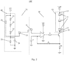
- Fig. 1 shows schematically a temperature adaptive control circuit 100 for a light emitting diode in accordance with an embodiment of the present application.
- the temperature adaptive control circuit 100 includes: a light emitting diode load circuit unit 10 in which one or more light emitting diodes 11 are connected (for example, connected in series or in parallel); and a temperature adaptive circuit unit 20 which includes a positive temperature coefficient (PTC) thermistor 21 and a negative temperature coefficient (NTC) thermistor 22 connected in series.
- PTC positive temperature coefficient
- NTC negative temperature coefficient
- the temperature adaptive circuit unit 20 is configured such that current flowing through the one or more light emitting diodes 11 in the light emitting diode load circuit unit 10 is a decreasing function of sum of resistance of the positive temperature coefficient thermistor 21 and resistance of the negative temperature coefficient thermistor 22.
- decreasing function means that the current flowing through the one or more light emitting diodes 11 in the light emitting diode load circuit unit 10 is reduced as the sum of resistance of the positive temperature coefficient thermistor 21 and resistance of the negative temperature coefficient thermistor 22 increases (for example, due to the change of temperature of the temperature adaptive circuit unit 20); otherwise, the current flowing through the one or more light emitting diodes 11 in the light emitting diode load circuit unit 10 increases as the sum of resistance of the positive temperature coefficient thermistor 21 and resistance of the negative temperature coefficient thermistor 22 is reduced.
- the positive temperature coefficient thermistor 21 and the negative temperature coefficient thermistor 22 are connected in series to the light emitting diode load circuit unit 10.
- the current flowing through the positive temperature coefficient thermistor 21 and the negative temperature coefficient thermistor 22 is reduced and thus the current flowing through the light emitting diodes 11 is also reduced , and vice versa.
- V_LED indicates a voltage applied to high voltage side of the light emitting diode load circuit unit 10, which may be determined depending on work voltage of the light emitting diodes.
- the current flowing through the light emitting diodes 11 arranged as a decreasing function of sum of resistance of the positive temperature coefficient thermistor 21 and resistance of the negative temperature coefficient thermistor 22, may achieve an adaptive control of the current on the basis of the temperature.
- the positive temperature coefficient thermistor 21 and the negative temperature coefficient thermistor 22 are connected in series to the light emitting diode load circuit unit 10.
- the embodiments of the present invention are not limited to this, for example, the positive temperature coefficient thermistor 21 and the negative temperature coefficient thermistor 22 may also be connected in parallel with the light emitting diode load circuit unit 10.
- the positive temperature coefficient thermistor 21 and the negative temperature coefficient thermistor 22 are two known types of thermistors in the art.
- each of the positive temperature coefficient thermistor 21 and the negative temperature coefficient thermistor 22 may be made from semiconductor ceramics, composite oxide ceramics, macromolecule materials or any other known materials in the art having property that their resistance changes as the temperature varies.
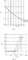
- Fig. 3 and Fig. 4 show a typical graph of resistance R NTC of a negative temperature coefficient thermistor 22 v.s. temperature T and a typical graph of resistance R PTC of a positive temperature coefficient thermistor 21 v.s. temperature T.
- the resistance R NTC and the resistance R PTC in Fig. 3 and Fig. 4 both are normalized. It can be seen from Fig. 3 that the resistance of the negative temperature coefficient thermistor 22 decreases gradually as the temperature increases.
- Fig. 3 shows change of the resistances of the negative temperature coefficient thermistors 22 having different material constants (3450, 3900, 4100). Fig.
- the change trend of resistances of the negative temperature coefficient thermistors 22 with variation of temperature is generally to opposite to that of resistances of the positive temperature coefficient thermistors 21 with variation of temperature.
- the resistances of the negative temperature coefficient thermistors 22 change in a relative stable manner as temperature varies.
- the resistances of the positive temperature coefficient thermistors 21 change a little in low temperature range, but change largely in a high temperature range. Based on the above characteristics, the negative temperature coefficient thermistor 22 and the positive temperature coefficient thermistor 21 may be used in combination to achieve good control of current of LED.
- the temperature is relatively low (for example, the temperature is lower than the curie temperature of the positive temperature coefficient thermistor 21)
- the resistance of the positive temperature coefficient thermistor 21 is influenced weakly by the temperature
- the change of the sum of resistance of the positive temperature coefficient thermistor 21 and resistance of the negative temperature coefficient thermistor 22 mainly depends on the negative temperature coefficient thermistor 22.
- the sum of resistance of the positive temperature coefficient thermistor 21 and resistance of the negative temperature coefficient thermistor 22 decreases gradually as the temperature rises, and correspondingly, the current flowing through the light emitting diodes 11 increases gradually.
- the luminescent intensity of the light emitting diodes 11 Due to the characteristics of the light emitting diodes 11 themselves, when the temperature rises, if their driving current is constant, their luminescent intensity will be reduced. It is the characteristics of the positive temperature coefficient thermistor 21 and the negative temperature coefficient thermistor 22 that may compensate the luminescent intensity of the light emitting diodes 11. In particular, when the luminescent intensity of the light emitting diodes 11 is reduced as the temperature rises, the current flowing through the light emitting diodes 11 may increase as temperature rises, as discussed above, thus, the luminescent intensity of the light emitting diodes 11 may increase due to increase of the current. In this way, it may compensate the luminescent intensity of the light emitting diodes 11.
- the luminescent intensity of the light emitting diodes 11 may be kept substantially constant, for example, the amplitude of variation of the luminescent intensity of the light emitting diodes 11 may be kept within 15% or 10%, as the temperature rises (in a normal work).
- embodiments of the present invention are not limited to this, as long as the positive temperature coefficient thermistor 21 and the negative temperature coefficient thermistor 22 can compensate the luminescent intensity of the light emitting diodes 11.
- the temperature is relatively high (for example, the temperature is greater than the curie temperature of the positive temperature coefficient thermistor 21)
- the resistance of the positive temperature coefficient thermistor 21 increases sharply as the temperature rises
- the change of the sum of resistance of the positive temperature coefficient thermistor 21 and resistance of the negative temperature coefficient thermistor 22 gradually becomes to mainly depend on the positive temperature coefficient thermistor 21.
- the sum of resistance of the positive temperature coefficient thermistor 21 and resistance of the negative temperature coefficient thermistor 22 increases significantly as the temperature rises, and correspondingly, the current flowing through the light emitting diodes 11 decreases significantly as the temperature rises.
- the characteristics of the positive temperature coefficient thermistor 21 and the negative temperature coefficient thermistor 22 may be used to provide overheating protection for the light emitting diodes 11.
- the skilled person in the art would appreciate that the light emitting diodes 11 should not work at a too high temperature; otherwise, it may be damaged.
- a predetermined overheating temperature may be set to prevent the work temperature of the light emitting diodes 11 from exceeding the overheating temperature to protect the light emitting diodes 11 from being damaged.
- the light emitting diodes 11 By causing the current flowing through the light emitting diodes 11 to begin to fall significantly at the predetermined overheating temperature or in the vicinity of the predetermined overheating temperature, even stopping the light emitting diodes 11 to work, the light emitting diodes 11 may be prevented from being damaged due to overheating.
- the temperature adaptive control circuit 100 can sufficiently use the characteristics of the positive temperature coefficient thermistor 21 and the negative temperature coefficient thermistor 22 to compensate the reduction of brightness of the light emitting diodes 11 caused by increase of the temperature so as to prevent the light emitting diodes 11 from being damaged due to overheating.
- the specific parameters of the positive temperature coefficient thermistor 21 and the negative temperature coefficient thermistor 22 may be selected as required.
- the temperature adaptive control circuit 100 adjusts the current flowing through the light emitting diodes 11 automatically depending on variation of the temperature, i.e., it is adaptive. Certainly, if required, operators may also adjust the work parameters or conditions of the temperature adaptive control circuit 100 as required.
- Fig. 5 shows an exemplary graph of the current I flowing through the light emitting diodes 11 v.s. the temperature T under the control of the temperature adaptive control circuit 100 according to an embodiment of the present invention.
- the left block (range from 20°Cto 50°C) in Fig. 5 shows an exemplary desired normal work temperature range Rn of LED. In the range Rn, the current increases gradually as the temperature increases.
- the right block in Fig. 5 shows a high temperature region Rh (60°Cto 110°C). In the high temperature region, the current reaches the peak value rapidly and then falls sharply.
- Fig. 5 shows three curves I_LED_max, I_LED_typ and I_LED_min. They correspond to the temperature adaptive control circuit 100 with different parameters respectively. It can be seen from Fig.
- Fig. 5 indicate current values of the LEDs when the LEDs are lighten for 1 minute and for 30 minutes. During lighting the LEDs from 1 minute to 30 minutes, the temperature of the LEDs will increase gradually due to the heat generated by the LEDs. On the basis of the above effects of the temperature adaptive control circuit 100, the current flowing through the LEDs may increase and the increase of the current may also raise the temperature in some extent. It can also be seen from variations of the two current values that the current in the Rn region increases as the temperature rises.
- Fig. 5 is illustrative, and embodiments of the present invention are not limited to this.
- the temperature adaptive circuit unit 20 has a temperature adaptive control node 23 and the voltage of the temperature adaptive control node 23 varies as the sum of the resistance of the positive temperature coefficient thermistor 21 and the resistance of the negative temperature coefficient thermistor 22 varies, and any one of two ends of the light emitting diode load circuit unit 10 is electrically connected with the temperature adaptive control node 23.
- the temperature adaptive control node 23 is a node connecting the light emitting diode load circuit unit 10 with the temperature adaptive circuit unit 20. It should be noted that the positions of the light emitting diode load circuit unit 10 and the temperature adaptive circuit unit 20 may be exchanged.
- the temperature adaptive control circuit 100' may further include: an intermediate circuit unit 30 having an input end 31, which is electrically connected to the temperature adaptive control node 23, and an output end 32, which is electrically connected to any one of two ends of the light emitting diode load circuit unit 10.
- the output end 32 is electrically connected to a low voltage end of the light emitting diode load circuit unit 10.
- the output end 32 of the intermediate circuit unit 30 may also be electrically connected to a high voltage end of the light emitting diode load circuit unit 10.
- the intermediate circuit unit 30 is used to connect the temperature adaptive control node 23 with the light emitting diode load circuit unit 10. It may for example improve the stability of system and flexibility of design.
- the intermediate circuit unit 30 may be configured such that the output current (or voltage) of the output end 32 is an increasing function of the voltage of the input end 31. So-called increasing function means that the output current (or voltage) of the output end 32 increases as the voltage of the input end 31 increases, otherwise, the output current (or voltage) of the output end 32 decreases as the voltage of the input end 31 decreases. It ensures that the temperature adaptive circuit unit 20 can control the voltage or current of the light emitting diode load circuit unit 10 by controlling the voltage of the temperature adaptive control node 23, so as to control the current flowing through the light emitting diodes 11.
- the intermediate circuit unit 30 may include operational amplifiers or other control chips or integrated circuits or the like, such as other known integrated circuit devices. It may be configured to improve anti-interference characteristics of circuits. Besides the operational amplifiers, the intermediate circuit unit 30 may further include corresponding resistors and capacitors (for example shown in Fig. 2 ) to achieve the corresponding functions. In the example shown in Fig. 2 , the intermediate circuit unit 30 includes elements such as an operational amplifier, a transistor, resistors R, Rs and a capacitor C. It may ensure the output current (or voltage) of the output end 32 to be an increasing function of the voltage of the input end 31. In the example shown in Fig.
- the intermediate circuit unit 30 is configured such that the voltage of the upper end node of the resistor Rs is substantially same to the voltage of the input end 31, for example, the difference between the voltage of the upper end node of the resistor Rs and the voltage of the input end 31 is not more than 10% of the latter. It is helpful to control the current flowing through the light emitting diodes 11 via the temperature adaptive control node 23. As an example, the difference between the voltage of the upper end node of the resistor Rs and the voltage of the input end 31 may not be more than 1% of the latter.
- a first node 13 and a second node 14 are provided at two ends of the light emitting diode load circuit unit 10 respectively.
- the first node 13 has a higher voltage than the second node 14, and the second node 14 is electrically connected to the output end 32 of the intermediate circuit unit 30.
- the output end 32 of the intermediate circuit unit 30 is electrically connected to the low voltage end (second node 14) of the light emitting diode load circuit unit 10.
- the output end 32 of the intermediate circuit unit 30 may also be electrically connected to the high voltage end (first node 13) of the light emitting diode load circuit unit 10.
- the intermediate circuit unit 30 includes a current control circuit (represented by a rectangular block in Fig. 6 ) and the current (or voltage) of its output end 32 may be an increasing function of the voltage of the input end 31. That is, the current (or voltage) of the output end 32 increases as the voltage of the input end 31 increases; otherwise, the current (or voltage) of the output end 32 decreases as the voltage of the input end 31 decreases.
- Such current (or voltage) control circuit may be in a form of integrated circuit, or may be in a form of separate circuits, which are known in the prior art. In the embodiment shown in Fig.
- the temperature adaptive circuit unit 20 may further include: a first resistor 27 connected in series with the positive temperature coefficient thermistor 21 and the negative temperature coefficient thermistor 22; and a second resistor 24 connected in parallel with the first resistor 27, the positive temperature coefficient thermistor 21 and the negative temperature coefficient thermistor 22 connected in series to form a parallel circuit unit 40, as shown in Fig. 2 .
- the first resistor 27 and the second resistor 24 may be arranged to adjust the ascent or descent slope of the current flowing through the LEDs.
- the skilled person in the art can select such as supply voltage, work current region of LEDs, ranges of resistances of the positive temperature coefficient thermistor 21 and the negative temperature coefficient thermistor 22.
- the first resistor 27 and the second resistor 24 may have resistances between 1k ⁇ and 100 k ⁇ , or may have resistances of tens of, hundreds of, or even several ohms.
- the temperature adaptive circuit unit 20 may further include a third resistor 25 and a capacitor 26, and the third resistor 25 is connected in parallel with the capacitor 26 and then connected in series with the parallel circuit unit 40.
- the third resistor 25 may be arranged to adjust the base voltage of the temperature adaptive control node 23 and the capacitor 26 may be arranged to remove AC interference signals.
- the relationship between the voltage of the temperature adaptive control node 23 and the above resistors may be determined from knowledge known in the art, such as Ohm's law, calculation of resistances of resistors connected in series or in parallel.
- the curie temperature of the positive temperature coefficient thermistor 21 is between a predetermined work temperature and a predetermined overheating temperature of the light emitting diodes 11. In this way, it may help the current to increase with the temperature in the predetermined work temperature of the light emitting diodes 11, but to begin to decrease when the temperature reaches or becomes close to the predetermined overheating temperature.
- the predetermined work temperature may be a desired work temperature of the light emitting diodes 11, such as room temperature.
- the predetermined overheating temperature may be set as required in practice. It is typically lower than the maximum temperature that the light emitting diodes 11 can be resisted to.
- the temperature adaptive circuit unit 20 may be configured such that the sum of the resistance of the positive temperature coefficient thermistor 21 and the resistance of the negative temperature coefficient thermistor 22 decreases before it reaches the predetermined overheating temperature as the temperature rises, while the sum of the resistance of the positive temperature coefficient thermistor 21 and the resistance of the negative temperature coefficient thermistor 22 increases after it reaches the predetermined overheating temperature as the temperature rises.
- the predetermined overheating temperature is meant to peak values of the curves in the example shown in Fig. 5 respectively.
- the sum of the resistance of the positive temperature coefficient thermistor 21 and the resistance of the negative temperature coefficient thermistor 22 increases slowly as the temperature rises; and after the temperature of the temperature adaptive circuit unit 20 reaches the predetermined overheating temperature, the sum of the resistance of the positive temperature coefficient thermistor 21 and the resistance of the negative temperature coefficient thermistor 22 decreases sharply as the temperature rises. It may help to achieve the above functions of luminescent intensity compensation and overheating protection.
- the current flowing through the light emitting diodes 11 is a decreasing function of sum of resistance of the positive temperature coefficient thermistor 21 and resistance of the negative temperature coefficient thermistor 22.
- the current flowing through the light emitting diodes 11 may also be an increasing function of sum of resistance of the positive temperature coefficient thermistor 21 and resistance of the negative temperature coefficient thermistor 22.
- a circuit structure different from those in the above embodiment may be needed. For example, in the example shown in Fig.
- the current flowing through the light emitting diodes 11 may become an increasing function of sum of resistance of the positive temperature coefficient thermistor 21 and resistance of the negative temperature coefficient thermistor 22.
- the effect of the positive temperature coefficient thermistor 21 and the effect of the negative temperature coefficient thermistor 22 may have functions opposite to those in the above embodiments, but they can also achieve the above luminescent intensity compensation function and overheating protection function.
- the concept of the present invention will be achieved.
- the characteristics of the positive temperature coefficient thermistor and the negative temperature coefficient thermistor are used in combination to achieve the above luminescent intensity compensation function and overheating protection function.
- the temperature adaptive control circuit 100, 100', 100" has a relatively simple structure and does need to be controlled by a computing device such as a microcontroller. It may also help to reduce costs and improve stability of system.
- the present application provides a lighting and/or signaling apparatus.
- the lighting and/or signaling apparatus may include: the temperature adaptive control circuit 100, 100', 100" for a light emitting diode as described in any one of the above embodiments.
Landscapes
- Circuit Arrangement For Electric Light Sources In General (AREA)
- Led Devices (AREA)
Abstract
Description
- The present application relates to the field of lighting and control, and in particular, to a temperature adaptive control circuit for a light emitting diode, a lighting and/or signaling apparatus.
- The light emitting diode (LED), as a light emitting device with low power consumption and high brightness, is applied in various apparatuses such as illumination, decoration, signaling apparatuses more and more widely. It is very crucial to control a current of the LED due to its high heat productivity. In order to ensure the LED to work stably, a complex feedback control loop circuit is typically used. However, such control circuit has a high cost, but single function of controlling current. It is desired to provide a cheap, multi-functional and reliable LED control circuit.
- The present application has an object of providing a temperature adaptive control circuit for a light emitting diode, which can adjust the current of the LED depending on change of conditions, such that the LED can emit a light stably and overheating protection can be provided for the LED. The present application also provides a lighting and/or signaling apparatus having the temperature adaptive control circuit.
- An embodiment of the present invention provides a temperature adaptive control circuit for a light emitting diode, including:
- a light emitting diode load circuit unit in which one or more light emitting diodes are connected; and
- a temperature adaptive circuit unit including a positive temperature coefficient thermistor and a negative temperature coefficient thermistor connected in series,
- In an embodiment, the temperature adaptive circuit unit is configured such that current flowing through the one or more light emitting diodes in the light emitting diode load circuit unit is a decreasing function of sum of resistance of the positive temperature coefficient thermistor and resistance of the negative temperature coefficient thermistor.
- In an embodiment, the positive temperature coefficient thermistor and the negative temperature coefficient thermistor are connected in series or in parallel with the light emitting diode load circuit unit.
- In an embodiment, the temperature adaptive circuit unit has a temperature adaptive control node and the voltage of the temperature adaptive control node varies as the sum of the resistance of the positive temperature coefficient thermistor and the resistance of the negative temperature coefficient thermistor varies, and any one of two ends of the light emitting diode load circuit unit is electrically connected with the temperature adaptive control node.
- In an embodiment, the temperature adaptive circuit unit has a temperature adaptive control node and the voltage of the temperature adaptive control node varies as the sum of the resistance of the positive temperature coefficient thermistor and the resistance of the negative temperature coefficient thermistor varies, and the temperature adaptive control circuit further includes:
- an intermediate circuit unit having an input end, which is electrically connected to the temperature adaptive control node, and an output end, which is electrically connected to any one of two ends of the light emitting diode load circuit unit.
- In an embodiment, the intermediate circuit unit is configured such that the voltage or current of the output end is an increasing function of the voltage of the input end.
- In an embodiment, a first node and a second node are provided at two ends of the light emitting diode load circuit unit respectively, the first node having a higher voltage than the second node, the first node being electrically connected to the output end of the intermediate circuit unit.
- In an embodiment, a first node and a second node are provided at two ends of the light emitting diode load circuit unit respectively, the first node having a higher voltage than the second node, the second node being electrically connected to the output end of the intermediate circuit unit.
- In an embodiment, the intermediate circuit unit includes an operational amplifier, or other control chips or integrated circuits.
- In an embodiment, the temperature adaptive circuit unit further includes:
- a first resistor connected in series with the positive temperature coefficient thermistor and the negative temperature coefficient thermistor; and
- a second resistor connected in parallel with the first resistor, the positive temperature coefficient thermistor and the negative temperature coefficient thermistor connected in series to form a parallel circuit unit.
- In an embodiment, the temperature adaptive circuit unit further includes a third resistor and a capacitor, and the third resistor is connected in parallel with the capacitor and then connected in series with the parallel circuit unit.
- In an embodiment, the positive temperature coefficient thermistor has a Curie temperature between a predetermined work temperature and a predetermined overheating temperature of the light emitting diode.
- In an embodiment, the temperature adaptive circuit unit is configured such that the sum of the resistance of the positive temperature coefficient thermistor and the resistance of the negative temperature coefficient thermistor decreases before it reaches the predetermined overheating temperature as the temperature rises, while the sum of the resistance of the positive temperature coefficient thermistor and the resistance of the negative temperature coefficient thermistor increases after it reaches the predetermined overheating temperature as the temperature rises.
- In an embodiment, the slope of change of the sum of the resistance of the positive temperature coefficient thermistor and the resistance of the negative temperature coefficient thermistor which decreases before it reaches the predetermined overheating temperature as the temperature rises, is less than the slope of change of the sum of the resistance of the positive temperature coefficient thermistor and the resistance of the negative temperature coefficient thermistor which increases after it reaches the predetermined overheating temperature as the temperature rises.
- An embodiment of the present invention also provides a lighting and/or signaling apparatus, including:
- the temperature adaptive control circuit for a light emitting diode as described in any one of the above embodiments.
- The temperature adaptive control circuit according to at least one of the above embodiments and the lighting and/or signaling apparatus including the temperature adaptive control circuit, not only can compensate the variation of the luminescent intensity of the LEDs with the temperature in a desired working temperature of the LEDs, but also can achieve overheating protection for the LEDs to avoid their damage.
-
-
Fig. 1 is a schematic view showing a temperature adaptive control circuit for a light emitting diode according to an embodiment of the present invention; -
Fig. 2 is a schematic view showing a temperature adaptive control circuit for a light emitting diode according to another embodiment of the present invention; -
Fig. 3 is a graph of resistance of a negative temperature coefficient thermistor v.s. temperature in an example; -
Fig. 4 is a graph of resistance of a positive temperature coefficient thermistor v.s. temperature in an example; -
Fig. 5 is a exemplary graph of a current passing through the LED v.s. temperature under the control of a temperature adaptive control circuit for a light emitting diode according to another embodiment of the present invention; and -
Fig. 6 is a schematic view showing a temperature adaptive control circuit for a light emitting diode according to a further embodiment of the present invention. - The embodiments of the present invention will be further explained below with reference to the figures and examples. Throughout the description, the same or similar reference numbers indicate the same or similar members. The following embodiments along with the figures are only used to explain the general concept of the present invention, instead of being intended to limit the scope of the present invention.
- According to the general inventive concept of the present disclosure, it provides a temperature adaptive control circuit for a light emitting diode, including: a light emitting diode load circuit unit in which one or more light emitting diodes are connected; and a temperature adaptive circuit unit including a positive temperature coefficient thermistor and a negative temperature coefficient thermistor connected in series, wherein the temperature adaptive circuit unit is configured such that current flowing through the one or more light emitting diodes in the light emitting diode load circuit unit is a function of sum of resistance of the positive temperature coefficient thermistor and resistance of the negative temperature coefficient thermistor.
- In addition, for the purpose of explanation, numerous specific details are set forth in the following detailed description to provide a thorough understanding to the embodiments of the present invention. It is obvious, however, that one or more embodiments can also be implemented without these specific details.
-
Fig. 1 shows schematically a temperatureadaptive control circuit 100 for a light emitting diode in accordance with an embodiment of the present application. The temperatureadaptive control circuit 100 includes: a light emitting diodeload circuit unit 10 in which one or morelight emitting diodes 11 are connected (for example, connected in series or in parallel); and a temperatureadaptive circuit unit 20 which includes a positive temperature coefficient (PTC)thermistor 21 and a negative temperature coefficient (NTC)thermistor 22 connected in series. The temperatureadaptive circuit unit 20 is configured such that current flowing through the one or morelight emitting diodes 11 in the light emitting diodeload circuit unit 10 is a decreasing function of sum of resistance of the positivetemperature coefficient thermistor 21 and resistance of the negativetemperature coefficient thermistor 22. - The skilled person in the art should understand that the above term of "decreasing function" means that the current flowing through the one or more
light emitting diodes 11 in the light emitting diodeload circuit unit 10 is reduced as the sum of resistance of the positivetemperature coefficient thermistor 21 and resistance of the negativetemperature coefficient thermistor 22 increases (for example, due to the change of temperature of the temperature adaptive circuit unit 20); otherwise, the current flowing through the one or morelight emitting diodes 11 in the light emitting diodeload circuit unit 10 increases as the sum of resistance of the positivetemperature coefficient thermistor 21 and resistance of the negativetemperature coefficient thermistor 22 is reduced. - For example, in the example shown in
Fig. 1 , the positivetemperature coefficient thermistor 21 and the negativetemperature coefficient thermistor 22 are connected in series to the light emitting diodeload circuit unit 10. Thus, when the sum of resistance of the positivetemperature coefficient thermistor 21 and resistance of the negativetemperature coefficient thermistor 22 increases, the current flowing through the positivetemperature coefficient thermistor 21 and the negativetemperature coefficient thermistor 22 is reduced and thus the current flowing through thelight emitting diodes 11 is also reduced , and vice versa. - In
Fig. 1 andFig. 2 , V_LED indicates a voltage applied to high voltage side of the light emitting diodeload circuit unit 10, which may be determined depending on work voltage of the light emitting diodes. - The current flowing through the
light emitting diodes 11 arranged as a decreasing function of sum of resistance of the positivetemperature coefficient thermistor 21 and resistance of the negativetemperature coefficient thermistor 22, may achieve an adaptive control of the current on the basis of the temperature. - In the above example shown in
Fig. 1 , the positivetemperature coefficient thermistor 21 and the negativetemperature coefficient thermistor 22 are connected in series to the light emitting diodeload circuit unit 10. However, the embodiments of the present invention are not limited to this, for example, the positivetemperature coefficient thermistor 21 and the negativetemperature coefficient thermistor 22 may also be connected in parallel with the light emitting diodeload circuit unit 10. - The positive
temperature coefficient thermistor 21 and the negativetemperature coefficient thermistor 22 are two known types of thermistors in the art. For example, each of the positivetemperature coefficient thermistor 21 and the negativetemperature coefficient thermistor 22 may be made from semiconductor ceramics, composite oxide ceramics, macromolecule materials or any other known materials in the art having property that their resistance changes as the temperature varies. -
Fig. 3 and Fig. 4 show a typical graph of resistance RNTC of a negativetemperature coefficient thermistor 22 v.s. temperature T and a typical graph of resistance RPTC of a positivetemperature coefficient thermistor 21 v.s. temperature T. In convenience of illustration, the resistance RNTC and the resistance RPTC inFig. 3 and Fig. 4 both are normalized. It can be seen fromFig. 3 that the resistance of the negativetemperature coefficient thermistor 22 decreases gradually as the temperature increases.Fig. 3 shows change of the resistances of the negativetemperature coefficient thermistors 22 having different material constants (3450, 3900, 4100).Fig. 4 shows change of the resistances of the positivetemperature coefficient thermistors 21 made from different materials (indicated by BD, BC, BB, AR). It can be seen fromFig. 4 that the resistances of the positivetemperature coefficient thermistors 21 change a little in a low temperature range as the temperature rises, however, once the temperature exceeds a certain temperature, the resistances will increase sharply as the temperature rises. The certain temperature is called as curie temperature. - It can be seen from
Fig. 3 and Fig. 4 that the change trend of resistances of the negativetemperature coefficient thermistors 22 with variation of temperature is generally to opposite to that of resistances of the positivetemperature coefficient thermistors 21 with variation of temperature. The resistances of the negativetemperature coefficient thermistors 22 change in a relative stable manner as temperature varies. In contrast, the resistances of the positivetemperature coefficient thermistors 21 change a little in low temperature range, but change largely in a high temperature range. Based on the above characteristics, the negativetemperature coefficient thermistor 22 and the positivetemperature coefficient thermistor 21 may be used in combination to achieve good control of current of LED. - At first, when the temperature is relatively low (for example, the temperature is lower than the curie temperature of the positive temperature coefficient thermistor 21), because the resistance of the positive
temperature coefficient thermistor 21 is influenced weakly by the temperature, the change of the sum of resistance of the positivetemperature coefficient thermistor 21 and resistance of the negativetemperature coefficient thermistor 22 mainly depends on the negativetemperature coefficient thermistor 22. Thus, the sum of resistance of the positivetemperature coefficient thermistor 21 and resistance of the negativetemperature coefficient thermistor 22 decreases gradually as the temperature rises, and correspondingly, the current flowing through thelight emitting diodes 11 increases gradually. Due to the characteristics of thelight emitting diodes 11 themselves, when the temperature rises, if their driving current is constant, their luminescent intensity will be reduced. It is the characteristics of the positivetemperature coefficient thermistor 21 and the negativetemperature coefficient thermistor 22 that may compensate the luminescent intensity of thelight emitting diodes 11. In particular, when the luminescent intensity of thelight emitting diodes 11 is reduced as the temperature rises, the current flowing through thelight emitting diodes 11 may increase as temperature rises, as discussed above, thus, the luminescent intensity of thelight emitting diodes 11 may increase due to increase of the current. In this way, it may compensate the luminescent intensity of thelight emitting diodes 11. As an example, with the above compensation effects of the positivetemperature coefficient thermistor 21 and the negativetemperature coefficient thermistor 22, the luminescent intensity of thelight emitting diodes 11 may be kept substantially constant, for example, the amplitude of variation of the luminescent intensity of thelight emitting diodes 11 may be kept within 15% or 10%, as the temperature rises (in a normal work). However, embodiments of the present invention are not limited to this, as long as the positivetemperature coefficient thermistor 21 and the negativetemperature coefficient thermistor 22 can compensate the luminescent intensity of thelight emitting diodes 11. - In addition, when the temperature is relatively high (for example, the temperature is greater than the curie temperature of the positive temperature coefficient thermistor 21), because the resistance of the positive
temperature coefficient thermistor 21 increases sharply as the temperature rises, the change of the sum of resistance of the positivetemperature coefficient thermistor 21 and resistance of the negativetemperature coefficient thermistor 22 gradually becomes to mainly depend on the positivetemperature coefficient thermistor 21. Thus, the sum of resistance of the positivetemperature coefficient thermistor 21 and resistance of the negativetemperature coefficient thermistor 22 increases significantly as the temperature rises, and correspondingly, the current flowing through thelight emitting diodes 11 decreases significantly as the temperature rises. The characteristics of the positivetemperature coefficient thermistor 21 and the negativetemperature coefficient thermistor 22 may be used to provide overheating protection for thelight emitting diodes 11. The skilled person in the art would appreciate that thelight emitting diodes 11 should not work at a too high temperature; otherwise, it may be damaged. Thus, a predetermined overheating temperature may be set to prevent the work temperature of thelight emitting diodes 11 from exceeding the overheating temperature to protect thelight emitting diodes 11 from being damaged. By causing the current flowing through thelight emitting diodes 11 to begin to fall significantly at the predetermined overheating temperature or in the vicinity of the predetermined overheating temperature, even stopping thelight emitting diodes 11 to work, thelight emitting diodes 11 may be prevented from being damaged due to overheating. - As discussed above, the temperature
adaptive control circuit 100 according to an embodiment of the present invention can sufficiently use the characteristics of the positivetemperature coefficient thermistor 21 and the negativetemperature coefficient thermistor 22 to compensate the reduction of brightness of thelight emitting diodes 11 caused by increase of the temperature so as to prevent thelight emitting diodes 11 from being damaged due to overheating. The specific parameters of the positivetemperature coefficient thermistor 21 and the negativetemperature coefficient thermistor 22 may be selected as required. And the temperatureadaptive control circuit 100 adjusts the current flowing through thelight emitting diodes 11 automatically depending on variation of the temperature, i.e., it is adaptive. Certainly, if required, operators may also adjust the work parameters or conditions of the temperatureadaptive control circuit 100 as required. -
Fig. 5 shows an exemplary graph of the current I flowing through thelight emitting diodes 11 v.s. the temperature T under the control of the temperatureadaptive control circuit 100 according to an embodiment of the present invention. The left block (range from 20°Cto 50°C) inFig. 5 shows an exemplary desired normal work temperature range Rn of LED. In the range Rn, the current increases gradually as the temperature increases. The right block inFig. 5 shows a high temperature region Rh (60°Cto 110°C). In the high temperature region, the current reaches the peak value rapidly and then falls sharply.Fig. 5 shows three curves I_LED_max, I_LED_typ and I_LED_min. They correspond to the temperatureadaptive control circuit 100 with different parameters respectively. It can be seen fromFig. 5 that the slope of variation (or called as variation ratio) of the current v.s. the temperature in an ascent section (current increases as the temperature rises) is smaller than the slope of variation of the current v.s. the temperature in a decent section (current decreases as the temperature rises). It may not only keep the stability of luminescent intensity of the LEDs in a normal work range, but also help to rapidly reduce the current when the temperature is relatively high, to avoid damage of the LEDs. For sake of convenience, current value of longitudinal ordinate inFig. 5 is shown in a form of percentage. The current value of 100% corresponds to the value of I_LED_typ at 25°C. Two vertical lines in the Rn region inFig. 5 indicate current values of the LEDs when the LEDs are lighten for 1 minute and for 30 minutes. During lighting the LEDs from 1 minute to 30 minutes, the temperature of the LEDs will increase gradually due to the heat generated by the LEDs. On the basis of the above effects of the temperatureadaptive control circuit 100, the current flowing through the LEDs may increase and the increase of the current may also raise the temperature in some extent. It can also be seen from variations of the two current values that the current in the Rn region increases as the temperature rises.Fig. 5 is illustrative, and embodiments of the present invention are not limited to this. - In an example, the temperature
adaptive circuit unit 20 has a temperatureadaptive control node 23 and the voltage of the temperatureadaptive control node 23 varies as the sum of the resistance of the positivetemperature coefficient thermistor 21 and the resistance of the negativetemperature coefficient thermistor 22 varies, and any one of two ends of the light emitting diodeload circuit unit 10 is electrically connected with the temperatureadaptive control node 23. In the example shown inFig. 1 , the temperatureadaptive control node 23 is a node connecting the light emitting diodeload circuit unit 10 with the temperatureadaptive circuit unit 20. It should be noted that the positions of the light emitting diodeload circuit unit 10 and the temperatureadaptive circuit unit 20 may be exchanged. - In an example, the temperature adaptive control circuit 100' may further include: an
intermediate circuit unit 30 having aninput end 31, which is electrically connected to the temperatureadaptive control node 23, and anoutput end 32, which is electrically connected to any one of two ends of the light emitting diodeload circuit unit 10. In the example shown inFig. 2 , theoutput end 32 is electrically connected to a low voltage end of the light emitting diodeload circuit unit 10. However, embodiments of the present invention are not limited to this. In other examples, theoutput end 32 of theintermediate circuit unit 30 may also be electrically connected to a high voltage end of the light emitting diodeload circuit unit 10. Theintermediate circuit unit 30 is used to connect the temperatureadaptive control node 23 with the light emitting diodeload circuit unit 10. It may for example improve the stability of system and flexibility of design. - As an example, the
intermediate circuit unit 30 may be configured such that the output current (or voltage) of theoutput end 32 is an increasing function of the voltage of theinput end 31. So-called increasing function means that the output current (or voltage) of theoutput end 32 increases as the voltage of theinput end 31 increases, otherwise, the output current (or voltage) of theoutput end 32 decreases as the voltage of theinput end 31 decreases. It ensures that the temperatureadaptive circuit unit 20 can control the voltage or current of the light emitting diodeload circuit unit 10 by controlling the voltage of the temperatureadaptive control node 23, so as to control the current flowing through thelight emitting diodes 11. - In an example, the
intermediate circuit unit 30 may include operational amplifiers or other control chips or integrated circuits or the like, such as other known integrated circuit devices. It may be configured to improve anti-interference characteristics of circuits. Besides the operational amplifiers, theintermediate circuit unit 30 may further include corresponding resistors and capacitors (for example shown inFig. 2 ) to achieve the corresponding functions. In the example shown inFig. 2 , theintermediate circuit unit 30 includes elements such as an operational amplifier, a transistor, resistors R, Rs and a capacitor C. It may ensure the output current (or voltage) of theoutput end 32 to be an increasing function of the voltage of theinput end 31. In the example shown inFig. 2 , theintermediate circuit unit 30 is configured such that the voltage of the upper end node of the resistor Rs is substantially same to the voltage of theinput end 31, for example, the difference between the voltage of the upper end node of the resistor Rs and the voltage of theinput end 31 is not more than 10% of the latter. It is helpful to control the current flowing through thelight emitting diodes 11 via the temperatureadaptive control node 23. As an example, the difference between the voltage of the upper end node of the resistor Rs and the voltage of theinput end 31 may not be more than 1% of the latter. - The specific circuit for achieving the above relation between the voltage of the upper end node of the resistor Rs and the voltage of the
input end 31 is known in the art, instead of being limited by the structure shown inFig. 2 . - In an example, a
first node 13 and asecond node 14 are provided at two ends of the light emitting diodeload circuit unit 10 respectively. Thefirst node 13 has a higher voltage than thesecond node 14, and thesecond node 14 is electrically connected to theoutput end 32 of theintermediate circuit unit 30. In the example shown inFig. 2 , theoutput end 32 of theintermediate circuit unit 30 is electrically connected to the low voltage end (second node 14) of the light emitting diodeload circuit unit 10. However, embodiments of the present invention are not limited to this. In other examples, theoutput end 32 of theintermediate circuit unit 30 may also be electrically connected to the high voltage end (first node 13) of the light emitting diodeload circuit unit 10.Fig. 6 shows a temperatureadaptive control circuit 100" according to a further embodiment of the present invention. In the example, theintermediate circuit unit 30 includes a current control circuit (represented by a rectangular block inFig. 6 ) and the current (or voltage) of itsoutput end 32 may be an increasing function of the voltage of theinput end 31. That is, the current (or voltage) of theoutput end 32 increases as the voltage of theinput end 31 increases; otherwise, the current (or voltage) of theoutput end 32 decreases as the voltage of theinput end 31 decreases. Such current (or voltage) control circuit may be in a form of integrated circuit, or may be in a form of separate circuits, which are known in the prior art. In the embodiment shown inFig. 6 , the output end of the current control circuit (i.e., theoutput end 32 of the intermediate circuit unit 30) is electrically connected to the high voltage end (first node 13) of the light emitting diodeload circuit unit 10. Such circuit structure may also be used to achieve control of current flowing through thelight emitting diodes 11 by the temperatureadaptive control node 23. - In an example, the temperature
adaptive circuit unit 20 may further include: afirst resistor 27 connected in series with the positivetemperature coefficient thermistor 21 and the negativetemperature coefficient thermistor 22; and asecond resistor 24 connected in parallel with thefirst resistor 27, the positivetemperature coefficient thermistor 21 and the negativetemperature coefficient thermistor 22 connected in series to form aparallel circuit unit 40, as shown inFig. 2 . Thefirst resistor 27 and thesecond resistor 24 may be arranged to adjust the ascent or descent slope of the current flowing through the LEDs. As required, the skilled person in the art can select such as supply voltage, work current region of LEDs, ranges of resistances of the positivetemperature coefficient thermistor 21 and the negativetemperature coefficient thermistor 22. For example, thefirst resistor 27 and thesecond resistor 24 may have resistances between 1kΩ and 100 kΩ, or may have resistances of tens of, hundreds of, or even several ohms. As an example, the temperatureadaptive circuit unit 20 may further include athird resistor 25 and acapacitor 26, and thethird resistor 25 is connected in parallel with thecapacitor 26 and then connected in series with theparallel circuit unit 40. Thethird resistor 25 may be arranged to adjust the base voltage of the temperatureadaptive control node 23 and thecapacitor 26 may be arranged to remove AC interference signals. The relationship between the voltage of the temperatureadaptive control node 23 and the above resistors may be determined from knowledge known in the art, such as Ohm's law, calculation of resistances of resistors connected in series or in parallel. - In an example, the curie temperature of the positive
temperature coefficient thermistor 21 is between a predetermined work temperature and a predetermined overheating temperature of thelight emitting diodes 11. In this way, it may help the current to increase with the temperature in the predetermined work temperature of thelight emitting diodes 11, but to begin to decrease when the temperature reaches or becomes close to the predetermined overheating temperature. The predetermined work temperature may be a desired work temperature of thelight emitting diodes 11, such as room temperature. The predetermined overheating temperature may be set as required in practice. It is typically lower than the maximum temperature that thelight emitting diodes 11 can be resisted to. - As an example, the temperature
adaptive circuit unit 20 may be configured such that the sum of the resistance of the positivetemperature coefficient thermistor 21 and the resistance of the negativetemperature coefficient thermistor 22 decreases before it reaches the predetermined overheating temperature as the temperature rises, while the sum of the resistance of the positivetemperature coefficient thermistor 21 and the resistance of the negativetemperature coefficient thermistor 22 increases after it reaches the predetermined overheating temperature as the temperature rises. The predetermined overheating temperature is meant to peak values of the curves in the example shown inFig. 5 respectively. - As an example, the slope of change of the sum of the resistance of the positive
temperature coefficient thermistor 21 and the resistance of the negativetemperature coefficient thermistor 22 which decreases before it reaches the predetermined overheating temperature as the temperature rises, is less than the slope of change of the sum of the resistance of the positivetemperature coefficient thermistor 21 and the resistance of the negativetemperature coefficient thermistor 22 which increases after it reaches the predetermined overheating temperature as the temperature rises. That is, before the temperature of the temperatureadaptive circuit unit 20 reaches the predetermined overheating temperature, the sum of the resistance of the positivetemperature coefficient thermistor 21 and the resistance of the negativetemperature coefficient thermistor 22 increases slowly as the temperature rises; and after the temperature of the temperatureadaptive circuit unit 20 reaches the predetermined overheating temperature, the sum of the resistance of the positivetemperature coefficient thermistor 21 and the resistance of the negativetemperature coefficient thermistor 22 decreases sharply as the temperature rises. It may help to achieve the above functions of luminescent intensity compensation and overheating protection. - In the above embodiment, the current flowing through the
light emitting diodes 11 is a decreasing function of sum of resistance of the positivetemperature coefficient thermistor 21 and resistance of the negativetemperature coefficient thermistor 22. However, embodiments of the present invention are not limited to this. For example, the current flowing through thelight emitting diodes 11 may also be an increasing function of sum of resistance of the positivetemperature coefficient thermistor 21 and resistance of the negativetemperature coefficient thermistor 22. In such case, a circuit structure different from those in the above embodiment may be needed. For example, in the example shown inFig. 1 , if the series connection of the positivetemperature coefficient thermistor 21 and the negativetemperature coefficient thermistor 22 and the light emitting diode load circuit unit is replaced by parallel connection of them, the current flowing through thelight emitting diodes 11 may become an increasing function of sum of resistance of the positivetemperature coefficient thermistor 21 and resistance of the negativetemperature coefficient thermistor 22. In this case, the effect of the positivetemperature coefficient thermistor 21 and the effect of the negativetemperature coefficient thermistor 22 may have functions opposite to those in the above embodiments, but they can also achieve the above luminescent intensity compensation function and overheating protection function. In fact, as long as the current flowing through the one or morelight emitting diodes 11 is a function of sum of resistance of the positivetemperature coefficient thermistor 21 and resistance of the negativetemperature coefficient thermistor 22, the concept of the present invention will be achieved. - In the temperature
adaptive control circuit adaptive control circuit - The present application provides a lighting and/or signaling apparatus. The lighting and/or signaling apparatus may include: the temperature
adaptive control circuit - Although the present description has been explained with reference to figures, the embodiments in figures are illustrative to explain the present disclosure, but are not intended to limit the present invention.
- Although some embodiments of the present invention have generally been illustrated and described , it would be appreciated by those skilled in the art that various modifications of the above embodiments may be made without departing from principles and concepts of the present invention. The scope of the present invention is defined by the appended claims and equivalents thereof.
Claims (15)
- A temperature adaptive control circuit for a light emitting diode, comprising:a light emitting diode load circuit unit in which one or more light emitting diodes are connected; anda temperature adaptive circuit unit comprising a positive temperature coefficient thermistor and a negative temperature coefficient thermistor connected in series,wherein the temperature adaptive circuit unit is configured such that current flowing through the one or more light emitting diodes in the light emitting diode load circuit unit is a function of sum of resistance of the positive temperature coefficient thermistor and resistance of the negative temperature coefficient thermistor.
- The temperature adaptive control circuit for a light emitting diode according to claim 1, wherein the temperature adaptive circuit unit is configured such that current flowing through the one or more light emitting diodes in the light emitting diode load circuit unit is a decreasing function of sum of resistance of the positive temperature coefficient thermistor and resistance of the negative temperature coefficient thermistor.
- The temperature adaptive control circuit for a light emitting diode according to claim 1, wherein the positive temperature coefficient thermistor and the negative temperature coefficient thermistor are connected in series or in parallel with the light emitting diode load circuit unit.
- The temperature adaptive control circuit for a light emitting diode according to claim 1, wherein the temperature adaptive circuit unit has a temperature adaptive control node and the voltage of the temperature adaptive control node varies as the sum of the resistance of the positive temperature coefficient thermistor and the resistance of the negative temperature coefficient thermistor varies, and any one of two ends of the light emitting diode load circuit unit is electrically connected with the temperature adaptive control node.
- The temperature adaptive control circuit for a light emitting diode according to claim 1, wherein the temperature adaptive circuit unit has a temperature adaptive control node and the voltage of the temperature adaptive control node varies as the sum of the resistance of the positive temperature coefficient thermistor and the resistance of the negative temperature coefficient thermistor varies, and the temperature adaptive control circuit further comprises:an intermediate circuit unit having an input end, which is electrically connected to the temperature adaptive control node, and an output end, which is electrically connected to any one of two ends of the light emitting diode load circuit unit.
- The temperature adaptive control circuit for a light emitting diode according to claim 5, wherein the intermediate circuit unit is configured such that the voltage or current of the output end is an increasing function of the voltage of the input end.
- The temperature adaptive control circuit for a light emitting diode according to claim 5, wherein a first node and a second node are provided at two ends of the light emitting diode load circuit unit respectively, the first node having a higher voltage than the second node, the first node being electrically connected to the output end of the intermediate circuit unit.
- The temperature adaptive control circuit for a light emitting diode according to claim 5, wherein a first node and a second node are provided at two ends of the light emitting diode load circuit unit respectively, the first node having a higher voltage than the second node, the second node being electrically connected to the output end of the intermediate circuit unit.
- The temperature adaptive control circuit for a light emitting diode according to claim 5, wherein the intermediate circuit unit comprises an operational amplifier, or other control chips or integrated circuits.
- The temperature adaptive control circuit for a light emitting diode according to any one of claims 1-9, wherein the temperature adaptive circuit unit further comprises:a first resistor connected in series with the positive temperature coefficient thermistor and the negative temperature coefficient thermistor; anda second resistor connected in parallel with the first resistor, the positive temperature coefficient thermistor and the negative temperature coefficient thermistor connected in series to form a parallel circuit unit.
- The temperature adaptive control circuit for a light emitting diode according to claim 10, wherein the temperature adaptive circuit unit further comprises a third resistor and a capacitor, and the third resistor is connected in parallel with the capacitor and then connected in series with the parallel circuit unit.
- The temperature adaptive control circuit for a light emitting diode according to any one of claims 1-9, wherein the positive temperature coefficient thermistor has a Curie temperature between a predetermined work temperature and a predetermined overheating temperature of the light emitting diode.
- The temperature adaptive control circuit for a light emitting diode according to any one of claims 1-9, wherein the temperature adaptive circuit unit is configured such that the sum of the resistance of the positive temperature coefficient thermistor and the resistance of the negative temperature coefficient thermistor decreases before it reaches the predetermined overheating temperature as the temperature rises, while the sum of the resistance of the positive temperature coefficient thermistor and the resistance of the negative temperature coefficient thermistor increases after it reaches the predetermined overheating temperature as the temperature rises.
- The temperature adaptive control circuit for a light emitting diode according to claim 13, wherein the slope of change of the sum of the resistance of the positive temperature coefficient thermistor and the resistance of the negative temperature coefficient thermistor which decreases before it reaches the predetermined overheating temperature as the temperature rises, is less than the slope of change of the sum of the resistance of the positive temperature coefficient thermistor and the resistance of the negative temperature coefficient thermistor which increases after it reaches the predetermined overheating temperature as the temperature rises.
- A lighting and/or signaling apparatus, comprising:the temperature adaptive control circuit for a light emitting diode according to any one of claims 1-14.
Applications Claiming Priority (1)
| Application Number | Priority Date | Filing Date | Title |
|---|---|---|---|
| CN201510887192.7A CN106851889B (en) | 2015-12-04 | 2015-12-04 | For the temperature self-adaptation control circuit of light emitting diode and illumination and/or signal indicating device |
Publications (2)
| Publication Number | Publication Date |
|---|---|
| EP3177112A1 true EP3177112A1 (en) | 2017-06-07 |
| EP3177112B1 EP3177112B1 (en) | 2021-08-25 |
Family
ID=57460422
Family Applications (1)
| Application Number | Title | Priority Date | Filing Date |
|---|---|---|---|
| EP16201719.8A Active EP3177112B1 (en) | 2015-12-04 | 2016-12-01 | Temperature adaptive control circuit for a light emitting diode, lighting and/or signaling apparatus |
Country Status (3)
| Country | Link |
|---|---|
| US (1) | US9854635B2 (en) |
| EP (1) | EP3177112B1 (en) |
| CN (1) | CN106851889B (en) |
Cited By (1)
| Publication number | Priority date | Publication date | Assignee | Title |
|---|---|---|---|---|
| EP3889496A1 (en) * | 2020-04-02 | 2021-10-06 | Toshiba Lighting & Technology Corporation | Vehicle luminaire and vehicle lighting tool |
Families Citing this family (7)
| Publication number | Priority date | Publication date | Assignee | Title |
|---|---|---|---|---|
| CN108575014B (en) * | 2017-08-10 | 2024-07-26 | 常州星宇车灯股份有限公司 | Circuit for raising current to be stable along with temperature rise by using thermistor PTC |
| CN108112135B (en) * | 2018-01-26 | 2023-10-27 | 广州汗马电子科技有限公司 | LED lamps and their power circuits |
| JP7524229B2 (en) * | 2020-01-20 | 2024-07-29 | 株式会社小糸製作所 | Lighting circuit and vehicle lamp |
| CN111464145B (en) * | 2020-04-07 | 2023-04-25 | 成都仕芯半导体有限公司 | Digital stepping attenuator |
| CN112332648B (en) * | 2020-11-13 | 2022-09-27 | 山特电子(深圳)有限公司 | Device and method for actively balancing thermal performance of parallel power devices |
| CN113556842B (en) * | 2021-06-29 | 2024-07-02 | 瓴芯电子科技(无锡)有限公司 | LED control method and system |
| TWI823430B (en) * | 2022-06-17 | 2023-11-21 | 國立中央大學 | Anti-blue light leakage led circuit structure with active thermal fuse |
Citations (2)
| Publication number | Priority date | Publication date | Assignee | Title |
|---|---|---|---|---|
| US20110068701A1 (en) * | 2009-09-24 | 2011-03-24 | Cree Led Lighting Solutions, Inc. | Solid state lighting apparatus with compensation bypass circuits and methods of operation thereof |
| US20110285324A1 (en) * | 2010-05-19 | 2011-11-24 | Lite-On Technology Corp. | Current regulating circuit and light emitting diode device having the same |
Family Cites Families (6)
| Publication number | Priority date | Publication date | Assignee | Title |
|---|---|---|---|---|
| US6111739A (en) * | 1999-08-11 | 2000-08-29 | Leotek Electronics Corporation | LED power supply with temperature compensation |
| KR100527099B1 (en) * | 2005-05-31 | 2005-11-09 | (주)일루텍 | Temperature compensation circuit for smps |
| US7750616B2 (en) * | 2007-06-21 | 2010-07-06 | Green Mark Technology Inc. | Buck converter LED driver circuit |
| US8476836B2 (en) * | 2010-05-07 | 2013-07-02 | Cree, Inc. | AC driven solid state lighting apparatus with LED string including switched segments |
| CN102569408A (en) * | 2012-02-28 | 2012-07-11 | 上海华力微电子有限公司 | SONOS (Silicon Oxide Nitride Oxide Silicon) unit transistor with high erasing speed and manufacturing method thereof |
| KR101547897B1 (en) * | 2012-12-21 | 2015-08-28 | 삼성전기주식회사 | Voltage control circuit with temperature compensation function |
-
2015
- 2015-12-04 CN CN201510887192.7A patent/CN106851889B/en active Active
-
2016
- 2016-12-01 EP EP16201719.8A patent/EP3177112B1/en active Active
- 2016-12-05 US US15/369,232 patent/US9854635B2/en active Active
Patent Citations (2)
| Publication number | Priority date | Publication date | Assignee | Title |
|---|---|---|---|---|
| US20110068701A1 (en) * | 2009-09-24 | 2011-03-24 | Cree Led Lighting Solutions, Inc. | Solid state lighting apparatus with compensation bypass circuits and methods of operation thereof |
| US20110285324A1 (en) * | 2010-05-19 | 2011-11-24 | Lite-On Technology Corp. | Current regulating circuit and light emitting diode device having the same |
Non-Patent Citations (1)
| Title |
|---|
| GARY -: "Principles of Linearizing the Thermistor.", 6 November 2012 (2012-11-06), XP055364601, Retrieved from the Internet <URL:http://create-and-make.com/principles-of-linearizing-the-thermistor/> [retrieved on 20170413] * |
Cited By (2)
| Publication number | Priority date | Publication date | Assignee | Title |
|---|---|---|---|---|
| EP3889496A1 (en) * | 2020-04-02 | 2021-10-06 | Toshiba Lighting & Technology Corporation | Vehicle luminaire and vehicle lighting tool |
| US11788706B2 (en) | 2020-04-02 | 2023-10-17 | Toshiba Lighting & Technology Corporation | Vehicle luminaire and vehicle lighting tool |
Also Published As
| Publication number | Publication date |
|---|---|
| US9854635B2 (en) | 2017-12-26 |
| EP3177112B1 (en) | 2021-08-25 |
| CN106851889A (en) | 2017-06-13 |
| US20170164443A1 (en) | 2017-06-08 |
| CN106851889B (en) | 2018-11-23 |
Similar Documents
| Publication | Publication Date | Title |
|---|---|---|
| US9854635B2 (en) | Temperature adaptive control circuit for a light emitting diode, lighting and/or signaling apparatus | |
| US10426009B2 (en) | Apparatus for precise temperature brightness compensation of LED | |
| JP5908555B2 (en) | Dimmable AC-driven light-emitting element lighting device | |
| US8779679B2 (en) | LED lamp, illumination device including the LED lamp and current control method of the LED lamp | |
| US8450943B2 (en) | Illuminating device and controlling method thereof | |
| EP1521503B1 (en) | Method and drive circuit for controlling leds | |
| US9398658B2 (en) | Lighting module and corresponding lighting system | |
| JP6025235B2 (en) | Intrinsically safe voltage clamp device | |
| TW201315280A (en) | Driving power and electronic device | |
| CA2750432A1 (en) | Temperature compensated led constant current source | |
| US8502479B2 (en) | Current regulating circuit and light emitting diode device having the same | |
| US10440797B2 (en) | Lighting device and illuminating fixture | |
| US8421370B2 (en) | Apparatus for driving a light emitting diode | |
| KR101308698B1 (en) | Thermally superior led circuit board | |
| KR102367335B1 (en) | Light-emitting diode driving module, method of operating thereof, and lighting apparatus including the same | |
| CN107210599B (en) | Front-end protection power controller | |
| CN105794317B (en) | Bleeder for improved dimming of LEDs | |
| KR102320590B1 (en) | Dimmable led lghiting device | |
| TWM461959U (en) | DC-to-DC constant current driving circuit | |
| CN102711328A (en) | Linear constant-current controller | |
| JP6619029B2 (en) | Input protection circuit for analog optocouplers | |
| KR102150267B1 (en) | Fail safe apparatus of led for vehicle | |
| KR102198793B1 (en) | Circuit for regulating intensity of light in LED(Light Emitting Diode) and method thereof | |
| KR20140029652A (en) | Apparatus for driving light emitting diode with reduction to total harmonics distortion | |
| US20160212819A1 (en) | Led driver and driving method |
Legal Events
| Date | Code | Title | Description |
|---|---|---|---|
| AK | Designated contracting states |
Kind code of ref document: A1 Designated state(s): AL AT BE BG CH CY CZ DE DK EE ES FI FR GB GR HR HU IE IS IT LI LT LU LV MC MK MT NL NO PL PT RO RS SE SI SK SM TR |
|
| AX | Request for extension of the european patent |
Extension state: BA ME |
|
| PUAI | Public reference made under article 153(3) epc to a published international application that has entered the european phase |
Free format text: ORIGINAL CODE: 0009012 |
|
| STAA | Information on the status of an ep patent application or granted ep patent |
Free format text: STATUS: THE APPLICATION HAS BEEN PUBLISHED |
|
| STAA | Information on the status of an ep patent application or granted ep patent |
Free format text: STATUS: REQUEST FOR EXAMINATION WAS MADE |
|
| 17P | Request for examination filed |
Effective date: 20171204 |
|
| RBV | Designated contracting states (corrected) |
Designated state(s): AL AT BE BG CH CY CZ DE DK EE ES FI FR GB GR HR HU IE IS IT LI LT LU LV MC MK MT NL NO PL PT RO RS SE SI SK SM TR |
|
| STAA | Information on the status of an ep patent application or granted ep patent |
Free format text: STATUS: EXAMINATION IS IN PROGRESS |
|
| 17Q | First examination report despatched |
Effective date: 20190227 |
|
| REG | Reference to a national code |
Ref country code: DE Ref legal event code: R079 Ref document number: 602016062662 Country of ref document: DE Free format text: PREVIOUS MAIN CLASS: H05B0033080000 Ipc: H05B0045395000 |
|
| GRAP | Despatch of communication of intention to grant a patent |
Free format text: ORIGINAL CODE: EPIDOSNIGR1 |
|
| STAA | Information on the status of an ep patent application or granted ep patent |
Free format text: STATUS: GRANT OF PATENT IS INTENDED |
|
| RIC1 | Information provided on ipc code assigned before grant |
Ipc: H05B 45/18 20200101ALI20210225BHEP Ipc: H05B 45/395 20200101AFI20210225BHEP |
|
| INTG | Intention to grant announced |
Effective date: 20210317 |
|
| GRAS | Grant fee paid |
Free format text: ORIGINAL CODE: EPIDOSNIGR3 |
|
| GRAA | (expected) grant |
Free format text: ORIGINAL CODE: 0009210 |
|
| STAA | Information on the status of an ep patent application or granted ep patent |
Free format text: STATUS: THE PATENT HAS BEEN GRANTED |
|
| AK | Designated contracting states |
Kind code of ref document: B1 Designated state(s): AL AT BE BG CH CY CZ DE DK EE ES FI FR GB GR HR HU IE IS IT LI LT LU LV MC MK MT NL NO PL PT RO RS SE SI SK SM TR |
|
| REG | Reference to a national code |
Ref country code: CH Ref legal event code: EP |
|
| REG | Reference to a national code |
Ref country code: IE Ref legal event code: FG4D Ref country code: AT Ref legal event code: REF Ref document number: 1425165 Country of ref document: AT Kind code of ref document: T Effective date: 20210915 |
|
| REG | Reference to a national code |
Ref country code: DE Ref legal event code: R096 Ref document number: 602016062662 Country of ref document: DE |
|
| REG | Reference to a national code |
Ref country code: LT Ref legal event code: MG9D |
|
| REG | Reference to a national code |
Ref country code: NL Ref legal event code: MP Effective date: 20210825 |
|
| REG | Reference to a national code |
Ref country code: AT Ref legal event code: MK05 Ref document number: 1425165 Country of ref document: AT Kind code of ref document: T Effective date: 20210825 |
|
| PG25 | Lapsed in a contracting state [announced via postgrant information from national office to epo] |
Ref country code: LT Free format text: LAPSE BECAUSE OF FAILURE TO SUBMIT A TRANSLATION OF THE DESCRIPTION OR TO PAY THE FEE WITHIN THE PRESCRIBED TIME-LIMIT Effective date: 20210825 Ref country code: AT Free format text: LAPSE BECAUSE OF FAILURE TO SUBMIT A TRANSLATION OF THE DESCRIPTION OR TO PAY THE FEE WITHIN THE PRESCRIBED TIME-LIMIT Effective date: 20210825 Ref country code: BG Free format text: LAPSE BECAUSE OF FAILURE TO SUBMIT A TRANSLATION OF THE DESCRIPTION OR TO PAY THE FEE WITHIN THE PRESCRIBED TIME-LIMIT Effective date: 20211125 Ref country code: NO Free format text: LAPSE BECAUSE OF FAILURE TO SUBMIT A TRANSLATION OF THE DESCRIPTION OR TO PAY THE FEE WITHIN THE PRESCRIBED TIME-LIMIT Effective date: 20211125 Ref country code: PT Free format text: LAPSE BECAUSE OF FAILURE TO SUBMIT A TRANSLATION OF THE DESCRIPTION OR TO PAY THE FEE WITHIN THE PRESCRIBED TIME-LIMIT Effective date: 20211227 Ref country code: ES Free format text: LAPSE BECAUSE OF FAILURE TO SUBMIT A TRANSLATION OF THE DESCRIPTION OR TO PAY THE FEE WITHIN THE PRESCRIBED TIME-LIMIT Effective date: 20210825 Ref country code: FI Free format text: LAPSE BECAUSE OF FAILURE TO SUBMIT A TRANSLATION OF THE DESCRIPTION OR TO PAY THE FEE WITHIN THE PRESCRIBED TIME-LIMIT Effective date: 20210825 Ref country code: HR Free format text: LAPSE BECAUSE OF FAILURE TO SUBMIT A TRANSLATION OF THE DESCRIPTION OR TO PAY THE FEE WITHIN THE PRESCRIBED TIME-LIMIT Effective date: 20210825 Ref country code: SE Free format text: LAPSE BECAUSE OF FAILURE TO SUBMIT A TRANSLATION OF THE DESCRIPTION OR TO PAY THE FEE WITHIN THE PRESCRIBED TIME-LIMIT Effective date: 20210825 Ref country code: RS Free format text: LAPSE BECAUSE OF FAILURE TO SUBMIT A TRANSLATION OF THE DESCRIPTION OR TO PAY THE FEE WITHIN THE PRESCRIBED TIME-LIMIT Effective date: 20210825 |
|
| PG25 | Lapsed in a contracting state [announced via postgrant information from national office to epo] |
Ref country code: PL Free format text: LAPSE BECAUSE OF FAILURE TO SUBMIT A TRANSLATION OF THE DESCRIPTION OR TO PAY THE FEE WITHIN THE PRESCRIBED TIME-LIMIT Effective date: 20210825 Ref country code: LV Free format text: LAPSE BECAUSE OF FAILURE TO SUBMIT A TRANSLATION OF THE DESCRIPTION OR TO PAY THE FEE WITHIN THE PRESCRIBED TIME-LIMIT Effective date: 20210825 Ref country code: GR Free format text: LAPSE BECAUSE OF FAILURE TO SUBMIT A TRANSLATION OF THE DESCRIPTION OR TO PAY THE FEE WITHIN THE PRESCRIBED TIME-LIMIT Effective date: 20211126 |
|
| PG25 | Lapsed in a contracting state [announced via postgrant information from national office to epo] |
Ref country code: NL Free format text: LAPSE BECAUSE OF FAILURE TO SUBMIT A TRANSLATION OF THE DESCRIPTION OR TO PAY THE FEE WITHIN THE PRESCRIBED TIME-LIMIT Effective date: 20210825 |
|
| PG25 | Lapsed in a contracting state [announced via postgrant information from national office to epo] |
Ref country code: DK Free format text: LAPSE BECAUSE OF FAILURE TO SUBMIT A TRANSLATION OF THE DESCRIPTION OR TO PAY THE FEE WITHIN THE PRESCRIBED TIME-LIMIT Effective date: 20210825 |
|
| REG | Reference to a national code |
Ref country code: DE Ref legal event code: R097 Ref document number: 602016062662 Country of ref document: DE |
|
| PG25 | Lapsed in a contracting state [announced via postgrant information from national office to epo] |
Ref country code: SM Free format text: LAPSE BECAUSE OF FAILURE TO SUBMIT A TRANSLATION OF THE DESCRIPTION OR TO PAY THE FEE WITHIN THE PRESCRIBED TIME-LIMIT Effective date: 20210825 Ref country code: SK Free format text: LAPSE BECAUSE OF FAILURE TO SUBMIT A TRANSLATION OF THE DESCRIPTION OR TO PAY THE FEE WITHIN THE PRESCRIBED TIME-LIMIT Effective date: 20210825 Ref country code: RO Free format text: LAPSE BECAUSE OF FAILURE TO SUBMIT A TRANSLATION OF THE DESCRIPTION OR TO PAY THE FEE WITHIN THE PRESCRIBED TIME-LIMIT Effective date: 20210825 Ref country code: EE Free format text: LAPSE BECAUSE OF FAILURE TO SUBMIT A TRANSLATION OF THE DESCRIPTION OR TO PAY THE FEE WITHIN THE PRESCRIBED TIME-LIMIT Effective date: 20210825 Ref country code: CZ Free format text: LAPSE BECAUSE OF FAILURE TO SUBMIT A TRANSLATION OF THE DESCRIPTION OR TO PAY THE FEE WITHIN THE PRESCRIBED TIME-LIMIT Effective date: 20210825 Ref country code: AL Free format text: LAPSE BECAUSE OF FAILURE TO SUBMIT A TRANSLATION OF THE DESCRIPTION OR TO PAY THE FEE WITHIN THE PRESCRIBED TIME-LIMIT Effective date: 20210825 |
|
| PLBE | No opposition filed within time limit |
Free format text: ORIGINAL CODE: 0009261 |
|
| STAA | Information on the status of an ep patent application or granted ep patent |
Free format text: STATUS: NO OPPOSITION FILED WITHIN TIME LIMIT |
|
| PG25 | Lapsed in a contracting state [announced via postgrant information from national office to epo] |
Ref country code: MC Free format text: LAPSE BECAUSE OF FAILURE TO SUBMIT A TRANSLATION OF THE DESCRIPTION OR TO PAY THE FEE WITHIN THE PRESCRIBED TIME-LIMIT Effective date: 20210825 Ref country code: IT Free format text: LAPSE BECAUSE OF FAILURE TO SUBMIT A TRANSLATION OF THE DESCRIPTION OR TO PAY THE FEE WITHIN THE PRESCRIBED TIME-LIMIT Effective date: 20210825 |
|
| REG | Reference to a national code |
Ref country code: CH Ref legal event code: PL |
|
| 26N | No opposition filed |
Effective date: 20220527 |
|
| GBPC | Gb: european patent ceased through non-payment of renewal fee |
Effective date: 20211201 |
|
| PG25 | Lapsed in a contracting state [announced via postgrant information from national office to epo] |
Ref country code: SI Free format text: LAPSE BECAUSE OF FAILURE TO SUBMIT A TRANSLATION OF THE DESCRIPTION OR TO PAY THE FEE WITHIN THE PRESCRIBED TIME-LIMIT Effective date: 20210825 |
|
| REG | Reference to a national code |
Ref country code: BE Ref legal event code: MM Effective date: 20211231 |
|
| PG25 | Lapsed in a contracting state [announced via postgrant information from national office to epo] |
Ref country code: LU Free format text: LAPSE BECAUSE OF NON-PAYMENT OF DUE FEES Effective date: 20211201 Ref country code: IE Free format text: LAPSE BECAUSE OF NON-PAYMENT OF DUE FEES Effective date: 20211201 Ref country code: GB Free format text: LAPSE BECAUSE OF NON-PAYMENT OF DUE FEES Effective date: 20211201 |
|
| PG25 | Lapsed in a contracting state [announced via postgrant information from national office to epo] |
Ref country code: BE Free format text: LAPSE BECAUSE OF NON-PAYMENT OF DUE FEES Effective date: 20211231 |
|
| PG25 | Lapsed in a contracting state [announced via postgrant information from national office to epo] |
Ref country code: LI Free format text: LAPSE BECAUSE OF NON-PAYMENT OF DUE FEES Effective date: 20211231 Ref country code: CH Free format text: LAPSE BECAUSE OF NON-PAYMENT OF DUE FEES Effective date: 20211231 |
|
| PG25 | Lapsed in a contracting state [announced via postgrant information from national office to epo] |
Ref country code: HU Free format text: LAPSE BECAUSE OF FAILURE TO SUBMIT A TRANSLATION OF THE DESCRIPTION OR TO PAY THE FEE WITHIN THE PRESCRIBED TIME-LIMIT; INVALID AB INITIO Effective date: 20161201 |
|
| PG25 | Lapsed in a contracting state [announced via postgrant information from national office to epo] |
Ref country code: CY Free format text: LAPSE BECAUSE OF FAILURE TO SUBMIT A TRANSLATION OF THE DESCRIPTION OR TO PAY THE FEE WITHIN THE PRESCRIBED TIME-LIMIT Effective date: 20210825 |
|
| P01 | Opt-out of the competence of the unified patent court (upc) registered |
Effective date: 20230602 |
|
| PG25 | Lapsed in a contracting state [announced via postgrant information from national office to epo] |
Ref country code: MK Free format text: LAPSE BECAUSE OF FAILURE TO SUBMIT A TRANSLATION OF THE DESCRIPTION OR TO PAY THE FEE WITHIN THE PRESCRIBED TIME-LIMIT Effective date: 20210825 |
|
| PG25 | Lapsed in a contracting state [announced via postgrant information from national office to epo] |
Ref country code: TR Free format text: LAPSE BECAUSE OF FAILURE TO SUBMIT A TRANSLATION OF THE DESCRIPTION OR TO PAY THE FEE WITHIN THE PRESCRIBED TIME-LIMIT Effective date: 20210825 |
|
| PG25 | Lapsed in a contracting state [announced via postgrant information from national office to epo] |
Ref country code: MT Free format text: LAPSE BECAUSE OF FAILURE TO SUBMIT A TRANSLATION OF THE DESCRIPTION OR TO PAY THE FEE WITHIN THE PRESCRIBED TIME-LIMIT Effective date: 20210825 |
|
| PGFP | Annual fee paid to national office [announced via postgrant information from national office to epo] |
Ref country code: FR Payment date: 20251230 Year of fee payment: 10 |
|
| PGFP | Annual fee paid to national office [announced via postgrant information from national office to epo] |
Ref country code: DE Payment date: 20251231 Year of fee payment: 10 |