EP3176803B1 - Controller and control method for alternating current contactor - Google Patents
Controller and control method for alternating current contactor Download PDFInfo
- Publication number
- EP3176803B1 EP3176803B1 EP15827157.7A EP15827157A EP3176803B1 EP 3176803 B1 EP3176803 B1 EP 3176803B1 EP 15827157 A EP15827157 A EP 15827157A EP 3176803 B1 EP3176803 B1 EP 3176803B1
- Authority
- EP
- European Patent Office
- Prior art keywords
- current
- circuit
- microcontroller
- output
- control
- Prior art date
- Legal status (The legal status is an assumption and is not a legal conclusion. Google has not performed a legal analysis and makes no representation as to the accuracy of the status listed.)
- Active
Links
Images

Classifications
-
- H—ELECTRICITY
- H02—GENERATION; CONVERSION OR DISTRIBUTION OF ELECTRIC POWER
- H02M—APPARATUS FOR CONVERSION BETWEEN AC AND AC, BETWEEN AC AND DC, OR BETWEEN DC AND DC, AND FOR USE WITH MAINS OR SIMILAR POWER SUPPLY SYSTEMS; CONVERSION OF DC OR AC INPUT POWER INTO SURGE OUTPUT POWER; CONTROL OR REGULATION THEREOF
- H02M7/00—Conversion of AC power input into DC power output; Conversion of DC power input into AC power output
- H02M7/02—Conversion of AC power input into DC power output without possibility of reversal
- H02M7/04—Conversion of AC power input into DC power output without possibility of reversal by static converters
-
- H—ELECTRICITY
- H01—ELECTRIC ELEMENTS
- H01H—ELECTRIC SWITCHES; RELAYS; SELECTORS; EMERGENCY PROTECTIVE DEVICES
- H01H47/00—Circuit arrangements not adapted to a particular application of the relay and designed to obtain desired operating characteristics or to provide energising current
- H01H47/02—Circuit arrangements not adapted to a particular application of the relay and designed to obtain desired operating characteristics or to provide energising current for modifying the operation of the relay
-
- H—ELECTRICITY
- H01—ELECTRIC ELEMENTS
- H01H—ELECTRIC SWITCHES; RELAYS; SELECTORS; EMERGENCY PROTECTIVE DEVICES
- H01H47/00—Circuit arrangements not adapted to a particular application of the relay and designed to obtain desired operating characteristics or to provide energising current
- H01H47/22—Circuit arrangements not adapted to a particular application of the relay and designed to obtain desired operating characteristics or to provide energising current for supplying energising current for relay coil
- H01H47/223—Circuit arrangements not adapted to a particular application of the relay and designed to obtain desired operating characteristics or to provide energising current for supplying energising current for relay coil adapted to be supplied by AC
-
- H—ELECTRICITY
- H01—ELECTRIC ELEMENTS
- H01H—ELECTRIC SWITCHES; RELAYS; SELECTORS; EMERGENCY PROTECTIVE DEVICES
- H01H47/00—Circuit arrangements not adapted to a particular application of the relay and designed to obtain desired operating characteristics or to provide energising current
- H01H47/22—Circuit arrangements not adapted to a particular application of the relay and designed to obtain desired operating characteristics or to provide energising current for supplying energising current for relay coil
- H01H47/32—Energising current supplied by semiconductor device
- H01H47/325—Energising current supplied by semiconductor device by switching regulator
-
- H—ELECTRICITY
- H02—GENERATION; CONVERSION OR DISTRIBUTION OF ELECTRIC POWER
- H02M—APPARATUS FOR CONVERSION BETWEEN AC AND AC, BETWEEN AC AND DC, OR BETWEEN DC AND DC, AND FOR USE WITH MAINS OR SIMILAR POWER SUPPLY SYSTEMS; CONVERSION OF DC OR AC INPUT POWER INTO SURGE OUTPUT POWER; CONTROL OR REGULATION THEREOF
- H02M1/00—Details of apparatus for conversion
- H02M1/12—Arrangements for reducing harmonics from AC input or output
-
- H—ELECTRICITY
- H02—GENERATION; CONVERSION OR DISTRIBUTION OF ELECTRIC POWER
- H02H—EMERGENCY PROTECTIVE CIRCUIT ARRANGEMENTS
- H02H3/00—Emergency protective circuit arrangements for automatic disconnection directly responsive to an undesired change from normal electric working condition with or without subsequent reconnection ; integrated protection
- H02H3/08—Emergency protective circuit arrangements for automatic disconnection directly responsive to an undesired change from normal electric working condition with or without subsequent reconnection ; integrated protection responsive to excess current
Definitions
- the invention relates to the technical field of low-voltage electric apparatus, more particularly, relates to a control technology of an alternating-current contactor.
- the Chinese patent application with the application number CN201210196762.4 , the publication number CN102709118A , and entitled "An energy-saving device of an alternating current contactor” discloses an energy-saving device of an alternating current contactor, comprising a peripheral circuit connected with the alternating current contactor and a signal processor connected with the peripheral circuit.
- the signal processor comprises a comparison circuit, a zero-crossing detection circuit, a pulse width modulation circuit, a selection circuit, a low-voltage detection circuit and a signal synthesis circuit.
- the energy-saving device disclosed by CN102709118A can only perform adjustable control of the PWM pulse width of small current during a holding stage of the electromagnet under different control voltages.
- the PWM pulse width is not adjustable.
- An attraction action of the electromagnet is driven by a plurality of fixed power frequency pulses, the amplitude and the dynamic characteristics of the attraction current cannot be controlled. Therefore, an attraction characteristic of the contactor is considerably influenced.
- This energy-saving device is not suitable for the applications which require frequent operations. A service life of the contactor is not good, while energy conservation is not facilitated.
- the PWM frequency of the small current for the holding stage is fixed to be a power frequency signal.
- a holding current can be kept as a constant current at a time level of 20ms
- the dynamic variation range of the small current within 20ms is large, and the working frequency band belongs to a human ear receivable range and cannot further reduce the running noise of the contactor, the service life of the contactor is also influenced.
- an automatic adjustment of the wide range of the control voltage cannot be realized. Therefore, the device cannot be applied to applications with large control voltage fluctuation.
- energy-saving devices and coils with different parameters are required to be configured in order to meet the requirements of different control voltages.
- the product model is increased, the management cost and the warehouse storage goods cost are correspondingly increased.
- the Chinese patent application with the application number CN201210530495.X , the publication number CN103021735A , and entitled "alternating current contactor intelligent control module with high-speed pulse width modulation function" discloses an alternating current contactor intelligent control module with a high-speed pulse width modulation function, comprising an AC/DC power supply supplying power for an alternating-current contactor coil through a rectifying and filtering circuit and a power electronic switch.
- the alternating current contactor intelligent control module further comprises a voltage sampling circuit, a single-chip microcomputer control system, a two-way DA conversion circuit, a sawtooth wave generation circuit, a square wave clock signal, a high-speed pulse width modulator, a bootstrap circuit, a compensation circuit, a switching point detection circuit, a hall current sensor, a follow current circuit, a low voltage holding loop and a constant voltage/constant current automatic switching circuit.
- An attraction stage and a holding stage of the electromagnet disclosed by CN103021735A adopt two completely different control strategies. During attraction, a current feedback loop detects a coil current through a hall current detector under a PWM control mode, the single-chip microcomputer controls an exciting current of an adjusting coil according to the current feedback signal.
- the attraction stage When the attraction stage is completed, it is switched to a low-voltage holding loop through a trigger switching point detection circuit, supplying direct power supply to the electromagnet coil during the holding stage to drive the electromagnet.
- two control loops an attraction control loop and a holding control loop
- the control mode further includes considerable hardware circuits such as a hall current sensor circuit and a trigger switching point detection circuit, and software expenditures. The cost is increased, more space is occupied. It is not suitable for the applications of small current contactors. The application range of this module is limited.
- WO 86/01332 A1 describes a control device for the electromagnet coil of a switching apparatus, comprising a MOS transistor switch in series with the coil, a double alternation rectifier supplying the coil, a signal regenerator having a closed-loop control circuit connected to a current reading element in the coil and providing to the switch a control signal having a call level and a hold level, and a voltage reducing circuit connected to the direct terminals of the coil.
- the closed-loop control circuit is connected to the MOS transistor grid and holds the current of the coil to a level independent of the source voltage.
- WO 02/33719 A1 describes a switching device comprising at least two operating coils for controlling at least two magnetic circuits, a control unit which controls the voltage supplied to the operating coils, and individual demagnetization circuits connected to each operating coil for achieving a simultaneous opening of the at least two magnetic circuits from all the operating coils.
- a follow current circuit is provided in an electromagnet coil circuit. For a large current contactor, the presence of the follow current circuit will cause a slow change of the coil current because of a large inductance of the coil, which will lengthen a releasing process of the contactor and considerably influence a releasing performance of the contactor.
- the present invention discloses a controller for an alternating current contactor.
- a controller for an alternating current contactor comprises:
- the controller further comprises a PLC control module adapted to be coupled to a single-bit dial switch configured to provide an enable signal to the PLC control module, wherein the PLC control module is adapted to output a PLC control signal to the microcontroller when the PLC control module is enabled by the single-bit dial switch, wherein the microcontroller is adapted to control the power transistor circuit according to the PLC control signal so as to control the electromagnet component to perform the actions of attraction, holding or releasing.
- a PLC control module adapted to be coupled to a single-bit dial switch configured to provide an enable signal to the PLC control module
- the PLC control module is adapted to output a PLC control signal to the microcontroller when the PLC control module is enabled by the single-bit dial switch
- the microcontroller is adapted to control the power transistor circuit according to the PLC control signal so as to control the electromagnet component to perform the actions of attraction, holding or releasing.
- the filtering and rectification circuit comprises:
- the input end of the filtering module includes two input terminals adapted to be connected to the external alternating current.
- the power supply module is adapted to output direct current power supplies with different voltages, wherein the power supply module is adapted to provide a 15V direct current power supply for the demagnetization circuit; the power supply module is adapted to provide a 12V direct current power supply for the MOS transistor driver; and the power supply module is adapted to provide 5V direct current power supplies for the current detector, the voltage detector, the microcontroller and the PLC control module.
- the PLC control module includes an AND gate, a first input end of the AND gate is an enable end adapted to receive the enable signal, a second input end of the AND gate is a control end adapted to receive the external control signal through an insulation circuit; when the enable end is enabled by the single-bit dial switch, the control end is adapted to input the external control signal into the AND gate, the AND gate is adapted to compute the enable signal on the enable end and the external control signal on the control end and output a result on the output end of the AND gate, wherein the output end of the AND gate is adapted to act as the output end of the PLC control module for outputting the PLC control signal to the microcontroller.
- a first input pin of the microcontroller is connected to the output end of the voltage detector, the first input pin is adapted to receive the voltage feedback signal; a second input pin of the microcontroller is connected to the output end of the current detector, the second input pin is adapted to receive the current feedback signal; a third input pin of the microcontroller is connected to the output end of the PLC control module, the third input pin is adapted to receive the PLC control signal; a first output pin of the microcontroller is connected to a control end of the demagnetization circuit, the first output pin is adapted to output a demagnetization control signal; a second output pin of the microcontroller is connected to a control end of the MOS transistor driver, the second output pin is adapted to output a MOS transistor driving signal; a third output pin of the microcontroller is connected to a control end of the switching circuit, the third output pin is adapted to output a switching control signal.
- a control method for an alternating current contactor comprises:
- the method further comprises enabling a PLC control module, the PLC outputting a PLC control signal to the microcontroller when enabled, the microcontroller controlling the power transistor circuit according to the PLC control signal so as to control the electromagnet component to perform actions of attraction, holding or releasing.
- the controller for an alternating current contactor of the present invention adopts a self-adaptive voltage-current dual loop control and provides a switchable PLC control mode. So that in a wide voltage range, a contactor is able to reliably attract during attraction, work with a basically constant current during holding, and rapidly break during releasing.
- the controller is small in size, low in cost and simple in switching between attraction and holding, and low in power consumption.
- the controller is applicable to contactors of all current-level.
- the present invention discloses a controller for an alternating current contactor.
- the controller comprises a filtering and rectification circuit, an electromagnet component, a power transistor circuit and a microcontroller.
- the filtering and rectification circuit is connected to external alternating current, filters and rectifies the external alternating current.
- the electromagnet component is driven by an output of the filtering and rectification circuit, performs actions of attraction, holding or releasing.
- the power transistor circuit is connected to the electromagnet component.
- the microcontroller is connected to the power transistor circuit. The microcontroller outputs a control signal to the power transistor circuit, the power transistor switches on or off according to the control signal so as to control the electromagnet component to perform the actions of attraction, holding or releasing.
- a control mode of the controller is as follows: a voltage feedback signal is obtained through a voltage control loop, a current feedback signal is obtained through a current control loop.
- the voltage control loop provides the voltage feedback signal to the microcontroller, the microcontroller generates a control signal according to the voltage feedback signal and outputs the control signal to the power transistor circuit.
- the control signal is a PWM control signal having different duty cycles during the attraction and holding of the electromagnet component.
- the PWM control signal having different duty cycles makes the current not exceed a predetermined current threshold during the attraction and holding of the electromagnet component.
- the current control loop provides the current feedback signal to the microcontroller, the microcontroller turns off the power transistor circuit upon detecting an overcurrent exceeding the current threshold.
- a PLC control module is provided.
- the PLC control module is connected to the microcontroller.
- the PLC control module outputs a PLC control signal to the microcontroller when enabled, the microcontroller controls the power transistor circuit according to the PLC control signal so as to control the electromagnet component to perform actions of attraction, holding or releasing.
- the PLC control module provides an extended control mode, adopting a weak electric signal to directly control attraction, holding or releasing of an electromagnet through a microcontroller.
- the control mode of the PLC control module is a supplement for an external power supply control mode (a strong power control).
- a switching circuit In order to adapt different peak currents during attraction and holding of the electromagnetic component, a switching circuit is provided.
- the switching circuit adjusts the current threshold according to different stages: during the attraction of the electromagnet component, the switching circuit is provided with a first current threshold. During the holding of the electromagnet component, the switching circuit is provided with a second current threshold. The first current threshold is larger than the second current threshold.
- the electromagnet component of the controller of the present invention is provided with an electromagnet coil, a follow current circuit and a demagnetization circuit.
- the follow current circuit is connected to the electromagnet coil, the follow current circuit works during attraction and holding of the electromagnetic coil to maintain the current in the electromagnet coil.
- the demagnetization circuit is connected to the electromagnet coil and works during releasing of the electromagnet coil, the demagnetization circuit raises a voltage on two ends of the electromagnet coil utilizing a characteristic that a current at two ends of an electromagnet coil cannot be changed suddenly, so that energy of the electromagnet coil is dissipated rapidly.
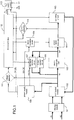
- FIG. 1 to Fig. 4 illustrate a circuit schematic diagram of a controller for an alternating current contactor according to an embodiment of the present invention, and circuit diagrams of some components and circuits therein.
- Fig. 1 illustrates a circuit schematic diagram of a controller for an alternating current contactor according to an embodiment of the present invention.
- a thicker line represents a power loop (a strong circuit loop), while a thinner line represents a control loop (a weak current loop).
- the controller comprises:
- a filtering module 101 the external alternating current is connected to an input end of the filtering module 101.
- the input end of the filtering module 101 includes two input terminals A1, A2, the external alternating current is inputted into the filtering module 101 through the two input terminals A1, A2.
- a rectification module 102 an input end of the rectification module 102 is connected to an output end of the filtering module 101.
- the filtering module 101 and the rectification module 102 filter and rectify the external alternating current and generate a pulse direct current.
- the rectification module 102 outputs the pulse direct current to an electromagnet coil 103, a power supply module 108 and a voltage detector 111.
- the rectification module 102 is also connected to a switching circuit 105 and receives a feedback signal from the switching circuit 105.
- the electromagnet coil 103, the follow current circuit 106 and the demagnetization circuit 107 form the electromagnet component.
- a first end M1 of the electromagnet coil 103 is connected to an output end of the rectification module 102.
- a second end M2 of the electromagnet coil 103 is connected to input ends of the follow current circuit 106 and the demagnetization circuit 107.
- Output ends of the follow current circuit 106 and the demagnetization circuit 107 are connected to the first end M1 of the electromagnet coil 103.
- the follow current circuit 106 and the demagnetization circuit 107 are generally parallel-connected.
- the follow current circuit 106 and the demagnetization circuit 107 operate alternately at different stages, which will be described in detail below.
- a power MOS transistor 104 and a MOS transistor driver 109 a source of the power MOS transistor 104 is connected to the second end M2 of the electromagnet coil 103.
- An output end of the MOS transistor driver 109 is connected to a gate of the power MOS transistor 104.
- a drain of the power MOS transistor 104 is connected to the switching circuit 105.
- a control end of the MOS transistor driver 109 is controlled by the microcontroller 112.
- the microcontroller 112 controls on or off of the power MOS transistor 104 through the MOS transistor driver 109.
- a switching circuit 105 an input end of the switching circuit 105 is connected to a drain of the power MOS transistor 104, an output end of the switching circuit 105 is connected to the rectification module 102.
- a control end of the switching circuit 105 is controlled by the microcontroller 112.
- a voltage detector 111 an input end of the voltage detector 111 is connected to the output end of the rectification module 102, an output end of the voltage detector 111 outputs the voltage feedback signal to the microcontroller 112.
- a current detector 110 an input end of the current detector 110 is connected to the drain of the power MOS transistor 104, an output end of the current detector 110 outputs the current feedback signal to the microcontroller 112.
- a PLC control module 113 an input end of the PLC control module 113 receives a logical control signal, an output end PLCON of the PLC control module outputs the PLC control signal.
- the PLC control module 113 provides an extended control mode, which may directly control the microcontroller 112 through the PLC control signal.
- Fig. 2 illustrates a structural diagram of a PLC control module in the controller for an alternating current contactor according to an embodiment of the present invention.
- the PLC control module 113 includes an AND gate, one input end of the AND gate is an enable end PLCEN, the other input end of the AND gate is a control end PLCD, the control end PLCD receives an external control signal through an insulation circuit.
- the enable end PLCEN may be connected to a single-bit dial switch, the single-bit dial switch achieves inputting of an enable signal.
- the insulation circuit may be realized by an optocoupler insulation circuit.
- PLCEN When PLCEN is enabled, the control signal of the control end PLCD is able to be inputted into the AND gate through the optocoupler insulation circuit.
- the signal inputted by the enable end PLCEN and the control signal inputted by the control end PLCD are computed in the AND gate and generate the PLC control signal.
- the PLC control signal is outputted to the microcontroller 112 through the output end PLCON.
- a microcontroller 112 receives the voltage feedback signal from the voltage detector 111, the current feedback signal from the current detector 110 and the PLC control signal from the PLC control module 113.
- the microcontroller 112 outputs control signals to the demagnetization circuit 107, the MOS transistor driver 109 and the switching circuit 105.
- a first input pin of the microcontroller 112 is connected to the output end of the voltage detector 111, the first input pin receives the voltage feedback signal.
- a second input pin of the microcontroller 112 is connected to the output end of the current detector 110, the second input pin receives the current feedback signal.
- a third input pin of the microcontroller 112 is connected to the output end PLCON of the PLC control module 113, the third input pin receives the PLC control signal.
- a first output pin of the microcontroller 112 is connected to a control end of the demagnetization circuit 107, the first output pin outputs a demagnetization control signal.
- a second output pin of the microcontroller 112 is connected to a control end of the MOS transistor driver 109, the second output pin outputs a MOS transistor driving signal.
- a third output pin of the microcontroller 112 is connected to a control end of the switching circuit 105, the third output pin outputs a switching control signal.
- a power supply module 108 an input end of the power supply module 108 is connected to the output end of the rectification module 102.
- the power supply module 108 supplies direct current to the demagnetization circuit 107, the MOS transistor driver 109, the current detector 110, the voltage detector 111, the microcontroller 112 and the PLC control module 113.
- the power supply module 108 outputs direct current (DC) power supplies with different voltages.
- the power supply module 108 provides a 15V DC power supply for the demagnetization circuit 107.
- the power supply module 108 provides a 12V DC power supply for the MOS transistor driver 109.
- the power supply module 108 provides 5V DC power supplies for the current detector 110, the voltage detector 111, the microcontroller 112 and the PLC control module 113.
- the frequency of the alternating current control voltage input by the external alternating current power supply is 50 Hz, and the alternating current control voltage is changed to be 100 Hz after being rectified by the rectification module 102.
- the voltage detector 111 processes the rectified voltage signal to obtain a voltage feedback signal, the voltage feedback signal is inputted to a voltage sampling port of the microcontroller 112, that is, the first input pin.
- the microcontroller 112 sets a sampling period of 10ms, and performs true effective value operation processing on the sampling points, so as to obtain an effective value of the control voltage.
- the effective value is used as a basis for controlling operation of the electromagnet component.
- the operation voltage of the contactor is 110 ⁇ 230V.
- a contactor must be able to reliably attract under 85% ⁇ 110% of the control voltage, and completely release under 20% ⁇ 75% of the control voltage. Therefore, it is determined that an attraction voltage is 90 ⁇ 255V, a holding voltage is 80 ⁇ 255V and a releasing voltage is 80V. There is a hysteresis voltage of 10V between the releasing voltage and a minimal value of the attraction voltage. The hysteresis voltage works as a threshold voltage which ensures reliable attraction and releasing of the electromagnet and prevents the contactor from fusion caused by shaking of the electromagnet.
- the microcontroller 112 outputs a control signal to the power transistor circuit according to the voltage range of the feedback voltage.
- the electromagnet is controlled by the power transistor circuit to perform corresponding actions. If the feedback voltage is the attraction voltage, the electromagnet is controlled to perform an attraction action. If the feedback voltage is the holding voltage, the electromagnet is controlled to execute a holding action. And if the feedback voltage is the releasing voltage, the electromagnet is controlled to perform a releasing action.
- the attraction voltage of the contactor is 90 ⁇ 255V and the holding voltage is 80 ⁇ 255V, which fall in a same range.
- the feedback voltage may be different.
- a PWM technology is applied to reliably control the electromagnet coil, so as to ensure that the contactor can reliably attract or hold under different control voltages.
- the microcontroller 112 controls the current during the attraction and holding stages by outputting PWM waveforms with different duty cycles to a MOS transistor driver and a power MOS transistor. PWM duty cycles for attraction or holding under different control voltages are stored in a FLASH or EEPROM of the microcontroller 112. When powered on, the microcontroller 112 reads the relevant PWM duty cycle from the FLASH or EEPROM.
- the microcontroller 112 After sampling 2 cycles (20ms) of the control voltage, the microcontroller 112 generates a set PWM waveform for controlling during the attraction stage according to the scale of the control voltage (wherein the control voltage is the voltage feedback signal outputted by the voltage detector 111). During this stage, the voltage detector 111 still continuously detects the control voltage so as to modify the PWM duty cycle in real time. Over several cycles (generally greater than 60ms, and my be different according to different characteristics of contactors, the time shall ensure that the contactor can be reliably attracted), the attraction action shall be completed, at this time, the microcontroller 112 adjusts the PWM duty cycle to a range corresponding to the holding stage according to the control voltage collected at that time and continuously adjusts the PWM duty cycle.
- the control method that adjusts the duty cycle according to the control voltage (the voltage feedback signal) in real time during the attraction and holding stages may achieve an optimal cooperation of an attraction force and a counter force, which can reduce bouncing of the iron core and facilitate a dynamic control so as to prolong a service life of the contactor.
- the control voltage that is, the voltage feedback signal
- the microcontroller 112 continues to use the control voltage as a basis of control and outputs a PWM signal with a corresponding duty cycle. If the feedback voltage is lower than 80V, the contactor performs a releasing action. If the feedback voltage is higher than the upper limit of the attraction voltage, such as 255V, the circuit needs to be turned off in time to protect the elements because a fault may occur at the moment which will cause an over voltage.
- the controller of the present invention is provided with a current detector 110.
- the current detector device 110 collects a current feedback signal and provides the current feedback signal to the microcontroller 112.
- the microcontroller 112 compares the current feedback signal collected by the current detector 110 with a current threshold value. When the current feedback signal is larger than the threshold value, it indicates that an over-current state occurs. At this time, the microcontroller 112 stops outputting the PWM signal to turn off the power transistor circuit.
- the microcontroller 112 should set different current thresholds for control for different stages.
- the switching circuit 105 is used to adjust the current thresholds at different stages.
- Fig. 3 illustrates a circuit diagram of a switching circuit in the controller for an alternating current contactor according to an embodiment of the present invention.
- the switching circuit 105 includes resistors R4, R5, R6, R7, R8, R9 and R10, a capacitor C1, a MOS transistor Q2.
- the resistors R4, R5 and R6 are connected in parallel, the resistor R7 is connected in series with the MOS transistor Q2 and then connected in parallel with the resistors R4, R5 and R6.
- the resistors R9 and R10 serve as auxiliary resistors of the control end.
- the resistor R9 is the control end "START" of the switching circuit 105 and is connected to the microcontroller 112.
- the resistor R8 and the capacitor C1 serve as the auxiliary resistors and capacitors of the input ends and the output ends.
- the terminal “Icoil” shown in Fig. 3 is the output end of the switching circuit 105.
- the terminal “In” shown in Fig. 3 is the input end of the switching circuit 105 and is connected to the drain of the power MOS transistor 104.
- the microcontroller 112 outputs a control signal to the control end "START".
- the control signal during attraction is a high level signal.
- the MOS transistor Q2 When the power MOS transistor 104 is conducted, the MOS transistor Q2 is conducted and resistors R4, R5, R6 and R7 form a parallel connection. A voltage signal on the resistor network is outputted from the end "icoil" to the microcontroller 112 as a feedback signal.
- the microcontroller 112 sets a large current threshold value corresponding to the attraction stage according to the feedback signal. After attraction, the signal outputted to the end "START" by the microcontroller 112 is a low level signal.
- the MOS transistor Q2 is turned off, the voltage signal on the resistor R7 is outputted from the end "Icoil” to the microcontroller 112 as a feedback signal.
- the microcontroller 112 sets a lower current threshold value corresponding to the holding stage according to the feedback signal.
- the voltage signal on the resistor network and the voltage signal on R7 are different, the microcontroller 112 can achieve a segmented control according to the difference between the signals.
- the controller of the present invention also includes a demagnetization circuit 107 in the electromagnet component.
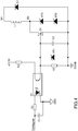
- Fig. 4 illustrates a circuit diagram of a demagnetization circuit in the controller for an alternating current contactor according to an embodiment of the present invention. As shown in Fig. 4 , the demagnetization circuit 107 is connected to both ends of electromagnet coil 103. In Fig. 4 , the electromagnet coil 103 is represented by "L1", the two ends of the "L1" are respectively end “M1" and end "M2".
- the demagnetization circuit 107 includes voltage stabilizing transistors VR1, VR2 and VR3, a diode D1, a MOS transistor Q1, resistors R1, R2 and R3, and capacitors C2 and C3.
- the end “+D15V” is the input of a power supply and is connected to the power supply module.
- the end “DeMagnet” is a control end and is connected to the microcontroller 112. When the contactor is in the attraction or holding stage, the signal outputted from the microcontroller 112 to the "DeMagnet” end is a high level signal.
- the power MOS transistor 104 is conducted, the MOS transistor Q1 is not conducted and a holding current flows through L1.
- the MOS transistor Q1 When the power MOS transistor 104 is turned off, the MOS transistor Q1 is conducted and a follow current flows through L1 via the MOS transistor Q1 and the diode D1.
- the signal outputted from the microcontroller 112 to the "DeMagnet" end is a low level signal.
- the MOS transistor Q1 is turned off, and the power MOS transistor 104 is turned off at the same time.
- L1 releases energy through the voltage stabilizing transistors VR2 and VR3 rapidly, so that the purpose of quickly releasing the electromagnet is achieved.
- the present invention further discloses a control method for an alternating current contactor, comprising:
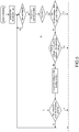
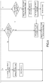
- Fig. 5 illustrates a logic diagram a control method for an alternating current contactor according to an example. As shown in Fig. 5 , the control method for an alternating current contactor is performed as follows: The system initializes and executes the initialization task.
- the control voltage > the attraction voltage determines whether the contactor is at an attraction position or not. If the contactor is not at the attraction position, then adjust the PWM duty cycle of the attraction stage, set a peak value of the attraction current, turn on the power MOS transistor, execute an attraction action and initiate an attraction delay. The peak value of the current is adjusted to be a peak value of the holding current after the time delay is reached. If the contactor is at the attraction position, then peak value of the holding current is set directly. After setting the peak value of the holding current, adjust the PWM duty cycle of the holding stage. Then the operation is completed and return to the step of detecting the interrupt flag bit, and wait for the next interrupt flag bit.
- the holding voltage ⁇ the control voltage ⁇ the attraction voltage determines whether the contactor is at the attraction position or not. If the contactor is at the attraction position, then set the peak value of the holding current, adjust the PWM duty cycle of the holding stage. Then the operation is completed and return to the step of detecting the interrupt flag bit, and wait for the next interrupt flag bit. If the contactor is not at the attraction position, then the operation is directly completed and return to the step of detecting the interrupt flag bit, and wait for the next interrupt flag bit.
Landscapes
- Engineering & Computer Science (AREA)
- Power Engineering (AREA)
- Relay Circuits (AREA)
- Electronic Switches (AREA)
- Rectifiers (AREA)
Description
- The invention relates to the technical field of low-voltage electric apparatus, more particularly, relates to a control technology of an alternating-current contactor.
- Most of the electronic control technologies of an alternating current contactor use a control circuit built by a single-chip microcomputer or discrete components as a core, and adopts a PWM (pulse-width modulation) control mode to drive an electromagnet of the alternating current contactor to achieve reliable attraction, holding or releasing. The overall technical parameters shall meet the requirements provided in Standard
GB 14048.4 - The Chinese patent application with the application number
CN201210196762.4 CN102709118A , and entitled "An energy-saving device of an alternating current contactor" discloses an energy-saving device of an alternating current contactor, comprising a peripheral circuit connected with the alternating current contactor and a signal processor connected with the peripheral circuit. The signal processor comprises a comparison circuit, a zero-crossing detection circuit, a pulse width modulation circuit, a selection circuit, a low-voltage detection circuit and a signal synthesis circuit. The energy-saving device disclosed byCN102709118A can only perform adjustable control of the PWM pulse width of small current during a holding stage of the electromagnet under different control voltages. However, during an attraction stage, the PWM pulse width is not adjustable. An attraction action of the electromagnet is driven by a plurality of fixed power frequency pulses, the amplitude and the dynamic characteristics of the attraction current cannot be controlled. Therefore, an attraction characteristic of the contactor is considerably influenced. This energy-saving device is not suitable for the applications which require frequent operations. A service life of the contactor is not good, while energy conservation is not facilitated. In addition, the PWM frequency of the small current for the holding stage is fixed to be a power frequency signal. Though a holding current can be kept as a constant current at a time level of 20ms, the dynamic variation range of the small current within 20ms is large, and the working frequency band belongs to a human ear receivable range and cannot further reduce the running noise of the contactor, the service life of the contactor is also influenced. Moreover, an automatic adjustment of the wide range of the control voltage cannot be realized. Therefore, the device cannot be applied to applications with large control voltage fluctuation. Meanwhile, energy-saving devices and coils with different parameters are required to be configured in order to meet the requirements of different control voltages. Thus the product model is increased, the management cost and the warehouse storage goods cost are correspondingly increased. - The Chinese patent application with the application number
CN201210530495.X CN103021735A , and entitled "alternating current contactor intelligent control module with high-speed pulse width modulation function" discloses an alternating current contactor intelligent control module with a high-speed pulse width modulation function, comprising an AC/DC power supply supplying power for an alternating-current contactor coil through a rectifying and filtering circuit and a power electronic switch. The alternating current contactor intelligent control module further comprises a voltage sampling circuit, a single-chip microcomputer control system, a two-way DA conversion circuit, a sawtooth wave generation circuit, a square wave clock signal, a high-speed pulse width modulator, a bootstrap circuit, a compensation circuit, a switching point detection circuit, a hall current sensor, a follow current circuit, a low voltage holding loop and a constant voltage/constant current automatic switching circuit. An attraction stage and a holding stage of the electromagnet disclosed byCN103021735A adopt two completely different control strategies. During attraction, a current feedback loop detects a coil current through a hall current detector under a PWM control mode, the single-chip microcomputer controls an exciting current of an adjusting coil according to the current feedback signal. When the attraction stage is completed, it is switched to a low-voltage holding loop through a trigger switching point detection circuit, supplying direct power supply to the electromagnet coil during the holding stage to drive the electromagnet. For the purpose of achieving normal operations of the contactor and an energy-saving mode of large attraction current and small holding current, two control loops (an attraction control loop and a holding control loop) are used in the whole control module, and the control mode further includes considerable hardware circuits such as a hall current sensor circuit and a trigger switching point detection circuit, and software expenditures. The cost is increased, more space is occupied. It is not suitable for the applications of small current contactors. The application range of this module is limited. However, for a large current contactor, due to the fact that more energy is required for the holding stage of the coils, a large capacity for sufficient power output is required so that a low-voltage holding circuit can provide sufficient energy to maintain the contact at a holding state, which may further increase the cost. -
WO 86/01332 A1 -
WO 02/33719 A1 - The present invention discloses a controller for an alternating current contactor.
- According to an embodiment of the present invention, a controller for an alternating current contactor is disclosed. The controller comprises:
- a filtering and rectification circuit adapted to be connected to an external alternating current and adapted to filter and rectify the external alternating current;
- an electromagnet component adapted to perform actions of attraction, holding or releasing, wherein the filtering and rectification circuit is adapted to drive;
- a power transistor circuit being connected to the electromagnet component;
- a microcontroller adapted to control on or off of the power transistor circuit so as to control the electromagnet component to perform the actions of attraction, holding or releasing, wherein the microcontroller is connected to the power transistor circuit.
- The controller further comprises a PLC control module adapted to be coupled to a single-bit dial switch configured to provide an enable signal to the PLC control module, wherein the PLC control module is adapted to output a PLC control signal to the microcontroller when the PLC control module is enabled by the single-bit dial switch, wherein the microcontroller is adapted to control the power transistor circuit according to the PLC control signal so as to control the electromagnet component to perform the actions of attraction, holding or releasing.
- The filtering and rectification circuit comprises:
- a filtering module comprising an input end adapted to be connected to the external alternating current; and
- a rectification module, an input end of the rectification module being connected to an output end of the filtering module;
- wherein the electromagnet component comprises an electromagnet coil, a follow current circuit and a demagnetization circuit, a first end of the electromagnet coil being connected to an output end of the rectification module, a second end of the electromagnet coil being connected to respective input ends of the follow current circuit and the demagnetization circuit, respective output ends of the follow current circuit and the demagnetization circuit being connected to the first end of the electromagnet coil;
- the power transistor circuit comprises a power MOS transistor and a MOS transistor driver, a source of the power MOS transistor being connected to the second end of the electromagnet coil, an output end of the MOS transistor driver being connected to a gate of the power MOS transistor;
- an input end of the switching circuit is connected to a drain of the power MOS transistor, an output end of the switching circuit being connected to the rectification module;
- the voltage control loop comprises a voltage detector, an input end of the voltage detector being connected to the output end of the rectification module, and an output end of the voltage detector being adapted to output the voltage feedback signal to the microcontroller;
- the current control loop comprises a current detector, an input end of the current detector being connected to the drain of the power MOS transistor, and an output end of the current detector being adapted to output the current feedback signal to the microcontroller;
- the PLC control module has an input end adapted to receive an external control signal, the PLC control module has an output end adapted to output the PLC control signal to the microcontroller;
- the microcontroller is adapted to receive the voltage feedback signal from the voltage detector, the current feedback signal from the current detector and the PLC control signal from the PLC control module, the microcontroller being adapted to output control signals to the demagnetization circuit and the switching circuit, the microcontroller being further adapted to provide the PWM control signal to the MOS transistor driver;
- the controller further comprising a power supply module, an input end of the power supply module being connected to the output end of the rectification module, the power supply module being adapted to supply direct current to the demagnetization circuit, the MOS transistor driver, the current detector, the voltage detector, the microcontroller and the PLC control module.
- According to an embodiment, the input end of the filtering module includes two input terminals adapted to be connected to the external alternating current.
- According to an embodiment, the power supply module is adapted to output direct current power supplies with different voltages, wherein the power supply module is adapted to provide a 15V direct current power supply for the demagnetization circuit; the power supply module is adapted to provide a 12V direct current power supply for the MOS transistor driver; and the power supply module is adapted to provide 5V direct current power supplies for the current detector, the voltage detector, the microcontroller and the PLC control module.
- According to an embodiment, the PLC control module includes an AND gate, a first input end of the AND gate is an enable end adapted to receive the enable signal, a second input end of the AND gate is a control end adapted to receive the external control signal through an insulation circuit;
when the enable end is enabled by the single-bit dial switch, the control end is adapted to input the external control signal into the AND gate, the AND gate is adapted to compute the enable signal on the enable end and the external control signal on the control end and output a result on the output end of the AND gate, wherein the output end of the AND gate is adapted to act as the output end of the PLC control module for outputting the PLC control signal to the microcontroller. - According to an embodiment, a first input pin of the microcontroller is connected to the output end of the voltage detector, the first input pin is adapted to receive the voltage feedback signal; a second input pin of the microcontroller is connected to the output end of the current detector, the second input pin is adapted to receive the current feedback signal; a third input pin of the microcontroller is connected to the output end of the PLC control module, the third input pin is adapted to receive the PLC control signal; a first output pin of the microcontroller is connected to a control end of the demagnetization circuit, the first output pin is adapted to output a demagnetization control signal; a second output pin of the microcontroller is connected to a control end of the MOS transistor driver, the second output pin is adapted to output a MOS transistor driving signal; a third output pin of the microcontroller is connected to a control end of the switching circuit, the third output pin is adapted to output a switching control signal.
- According to an example, a control method for an alternating current contactor is provided, the method comprises:
- filtering and rectifying an external alternating current, and driving an electromagnet component by the external alternating current so filtered and rectified;
- controlling on or off of a power transistor circuit by a microcontroller, the on or off of the power transistor circuit making the electromagnet component perform the actions of attraction, holding or releasing;
- sampling a voltage feedback signal, the microcontroller generating a control signal according to the voltage feedback signal and controlling the power transistor circuit with the control signal, so that the electromagnet component performs the actions of attraction, holding or releasing, wherein the control signal is a PWM control signal having different duty cycles during the attraction and holding of the electromagnet component, the PWM control signal having different duty cycles makes the current provided by the filtering and rectifying not exceed a predetermined current threshold during the attraction and holding of the electromagnet component;
- sampling a current feedback signal, the microcontroller turning off the power transistor circuit upon detecting an overcurrent exceeding the current threshold; and
- providing a switching circuit for adjusting the current threshold to a predetermined value, wherein during the attraction of the electromagnet component, the switching circuit is adapted to adjust the current threshold to a first current threshold, and during the holding of the electromagnet component, the switching circuit is adapted to adjust the current threshold to a second current threshold, the first current threshold is larger than the second current threshold.
- According to an example, the method further comprises enabling a PLC control module, the PLC outputting a PLC control signal to the microcontroller when enabled, the microcontroller controlling the power transistor circuit according to the PLC control signal so as to control the electromagnet component to perform actions of attraction, holding or releasing.
- The controller for an alternating current contactor of the present invention adopts a self-adaptive voltage-current dual loop control and provides a switchable PLC control mode. So that in a wide voltage range, a contactor is able to reliably attract during attraction, work with a basically constant current during holding, and rapidly break during releasing. The controller is small in size, low in cost and simple in switching between attraction and holding, and low in power consumption. The controller is applicable to contactors of all current-level.
- The above and other features, natures, and advantages of the invention will be apparent by the following description of the embodiments incorporating the drawings, wherein,
-
Fig 1 illustrates a circuit schematic diagram of a controller for an alternating current contactor according to an embodiment of the present invention. -
Fig 2 illustrates a structural diagram of a PLC control module in the controller for an alternating current contactor according to an embodiment of the present invention. -
Fig 3 illustrates a circuit diagram of a switching circuit in the controller for an alternating current contactor according to an embodiment of the present invention. -
Fig 4 illustrates a circuit diagram of a demagnetization circuit in the controller for an alternating current contactor according to an embodiment of the present invention. -
Fig 5 illustrates a logic diagram a control method for an alternating current contactor according to an example. - The present invention discloses a controller for an alternating current contactor. The controller comprises a filtering and rectification circuit, an electromagnet component, a power transistor circuit and a microcontroller. The filtering and rectification circuit is connected to external alternating current, filters and rectifies the external alternating current. The electromagnet component is driven by an output of the filtering and rectification circuit, performs actions of attraction, holding or releasing. The power transistor circuit is connected to the electromagnet component. The microcontroller is connected to the power transistor circuit. The microcontroller outputs a control signal to the power transistor circuit, the power transistor switches on or off according to the control signal so as to control the electromagnet component to perform the actions of attraction, holding or releasing.
- A control mode of the controller is as follows: a voltage feedback signal is obtained through a voltage control loop, a current feedback signal is obtained through a current control loop. The voltage control loop provides the voltage feedback signal to the microcontroller, the microcontroller generates a control signal according to the voltage feedback signal and outputs the control signal to the power transistor circuit. The control signal is a PWM control signal having different duty cycles during the attraction and holding of the electromagnet component. The PWM control signal having different duty cycles makes the current not exceed a predetermined current threshold during the attraction and holding of the electromagnet component. The current control loop provides the current feedback signal to the microcontroller, the microcontroller turns off the power transistor circuit upon detecting an overcurrent exceeding the current threshold.
- A PLC control module is provided. The PLC control module is connected to the microcontroller. The PLC control module outputs a PLC control signal to the microcontroller when enabled, the microcontroller controls the power transistor circuit according to the PLC control signal so as to control the electromagnet component to perform actions of attraction, holding or releasing. The PLC control module provides an extended control mode, adopting a weak electric signal to directly control attraction, holding or releasing of an electromagnet through a microcontroller. As an extension, the control mode of the PLC control module is a supplement for an external power supply control mode (a strong power control).
- In order to adapt different peak currents during attraction and holding of the electromagnetic component, a switching circuit is provided. The switching circuit adjusts the current threshold according to different stages: during the attraction of the electromagnet component, the switching circuit is provided with a first current threshold. During the holding of the electromagnet component, the switching circuit is provided with a second current threshold. The first current threshold is larger than the second current threshold.
- In order to achieve a reliable attraction during attraction, a stable current during holding and a rapid release during releasing, the electromagnet component of the controller of the present invention is provided with an electromagnet coil, a follow current circuit and a demagnetization circuit. The follow current circuit is connected to the electromagnet coil, the follow current circuit works during attraction and holding of the electromagnetic coil to maintain the current in the electromagnet coil. The demagnetization circuit is connected to the electromagnet coil and works during releasing of the electromagnet coil, the demagnetization circuit raises a voltage on two ends of the electromagnet coil utilizing a characteristic that a current at two ends of an electromagnet coil cannot be changed suddenly, so that energy of the electromagnet coil is dissipated rapidly.
- Referring to
Fig. 1 to Fig. 4 , which illustrate a circuit schematic diagram of a controller for an alternating current contactor according to an embodiment of the present invention, and circuit diagrams of some components and circuits therein. - Referring to
Fig. 1, Fig. 1 illustrates a circuit schematic diagram of a controller for an alternating current contactor according to an embodiment of the present invention. According toFig. 1 , a thicker line represents a power loop (a strong circuit loop), while a thinner line represents a control loop (a weak current loop). The controller comprises: - A
filtering module 101, the external alternating current is connected to an input end of thefiltering module 101. According to the embodiment shown inFig. 1 , the input end of thefiltering module 101 includes two input terminals A1, A2, the external alternating current is inputted into thefiltering module 101 through the two input terminals A1, A2. - A
rectification module 102, an input end of therectification module 102 is connected to an output end of thefiltering module 101. Thefiltering module 101 and therectification module 102 filter and rectify the external alternating current and generate a pulse direct current. Therectification module 102 outputs the pulse direct current to anelectromagnet coil 103, apower supply module 108 and avoltage detector 111. Therectification module 102 is also connected to aswitching circuit 105 and receives a feedback signal from the switchingcircuit 105. - The
electromagnet coil 103, the followcurrent circuit 106 and thedemagnetization circuit 107 form the electromagnet component. A first end M1 of theelectromagnet coil 103 is connected to an output end of therectification module 102. A second end M2 of theelectromagnet coil 103 is connected to input ends of the followcurrent circuit 106 and thedemagnetization circuit 107. Output ends of the followcurrent circuit 106 and thedemagnetization circuit 107 are connected to the first end M1 of theelectromagnet coil 103. The followcurrent circuit 106 and thedemagnetization circuit 107 are generally parallel-connected. The followcurrent circuit 106 and thedemagnetization circuit 107 operate alternately at different stages, which will be described in detail below. - A
power MOS transistor 104 and aMOS transistor driver 109, a source of thepower MOS transistor 104 is connected to the second end M2 of theelectromagnet coil 103. An output end of theMOS transistor driver 109 is connected to a gate of thepower MOS transistor 104. A drain of thepower MOS transistor 104 is connected to theswitching circuit 105. A control end of theMOS transistor driver 109 is controlled by themicrocontroller 112. Themicrocontroller 112 controls on or off of thepower MOS transistor 104 through theMOS transistor driver 109. - A switching
circuit 105, an input end of theswitching circuit 105 is connected to a drain of thepower MOS transistor 104, an output end of theswitching circuit 105 is connected to therectification module 102. A control end of theswitching circuit 105 is controlled by themicrocontroller 112. - A
voltage detector 111, an input end of thevoltage detector 111 is connected to the output end of therectification module 102, an output end of thevoltage detector 111 outputs the voltage feedback signal to themicrocontroller 112. - A
current detector 110, an input end of thecurrent detector 110 is connected to the drain of thepower MOS transistor 104, an output end of thecurrent detector 110 outputs the current feedback signal to themicrocontroller 112. - A
PLC control module 113, an input end of thePLC control module 113 receives a logical control signal, an output end PLCON of the PLC control module outputs the PLC control signal. ThePLC control module 113 provides an extended control mode, which may directly control themicrocontroller 112 through the PLC control signal. Referring toFig. 2, Fig. 2 illustrates a structural diagram of a PLC control module in the controller for an alternating current contactor according to an embodiment of the present invention. ThePLC control module 113 includes an AND gate, one input end of the AND gate is an enable end PLCEN, the other input end of the AND gate is a control end PLCD, the control end PLCD receives an external control signal through an insulation circuit. According to an embodiment, the enable end PLCEN may be connected to a single-bit dial switch, the single-bit dial switch achieves inputting of an enable signal. The insulation circuit may be realized by an optocoupler insulation circuit. When PLCEN is enabled, the control signal of the control end PLCD is able to be inputted into the AND gate through the optocoupler insulation circuit. The signal inputted by the enable end PLCEN and the control signal inputted by the control end PLCD are computed in the AND gate and generate the PLC control signal. The PLC control signal is outputted to themicrocontroller 112 through the output end PLCON. - A
microcontroller 112, themicrocontroller 112 receives the voltage feedback signal from thevoltage detector 111, the current feedback signal from thecurrent detector 110 and the PLC control signal from thePLC control module 113. Themicrocontroller 112 outputs control signals to thedemagnetization circuit 107, theMOS transistor driver 109 and theswitching circuit 105. According to the embodiments shown inFig. 1 , a first input pin of themicrocontroller 112 is connected to the output end of thevoltage detector 111, the first input pin receives the voltage feedback signal. A second input pin of themicrocontroller 112 is connected to the output end of thecurrent detector 110, the second input pin receives the current feedback signal. A third input pin of themicrocontroller 112 is connected to the output end PLCON of thePLC control module 113, the third input pin receives the PLC control signal. A first output pin of themicrocontroller 112 is connected to a control end of thedemagnetization circuit 107, the first output pin outputs a demagnetization control signal. A second output pin of themicrocontroller 112 is connected to a control end of theMOS transistor driver 109, the second output pin outputs a MOS transistor driving signal. A third output pin of themicrocontroller 112 is connected to a control end of theswitching circuit 105, the third output pin outputs a switching control signal. - A
power supply module 108, an input end of thepower supply module 108 is connected to the output end of therectification module 102. Thepower supply module 108 supplies direct current to thedemagnetization circuit 107, theMOS transistor driver 109, thecurrent detector 110, thevoltage detector 111, themicrocontroller 112 and thePLC control module 113. According to the embodiment shown inFig. 1 , thepower supply module 108 outputs direct current (DC) power supplies with different voltages. Wherein, thepower supply module 108 provides a 15V DC power supply for thedemagnetization circuit 107. Thepower supply module 108 provides a 12V DC power supply for theMOS transistor driver 109. Thepower supply module 108 provides 5V DC power supplies for thecurrent detector 110, thevoltage detector 111, themicrocontroller 112 and thePLC control module 113. - The frequency of the alternating current control voltage input by the external alternating current power supply is 50 Hz, and the alternating current control voltage is changed to be 100 Hz after being rectified by the
rectification module 102. Thevoltage detector 111 processes the rectified voltage signal to obtain a voltage feedback signal, the voltage feedback signal is inputted to a voltage sampling port of themicrocontroller 112, that is, the first input pin. Themicrocontroller 112 sets a sampling period of 10ms, and performs true effective value operation processing on the sampling points, so as to obtain an effective value of the control voltage. The effective value is used as a basis for controlling operation of the electromagnet component. The operation voltage of the contactor is 110∼230V. According to the provisions ofGB14048.4-2010 microcontroller 112 outputs a control signal to the power transistor circuit according to the voltage range of the feedback voltage. The electromagnet is controlled by the power transistor circuit to perform corresponding actions. If the feedback voltage is the attraction voltage, the electromagnet is controlled to perform an attraction action. If the feedback voltage is the holding voltage, the electromagnet is controlled to execute a holding action. And if the feedback voltage is the releasing voltage, the electromagnet is controlled to perform a releasing action. - As described above, the attraction voltage of the contactor is 90 ∼255V and the holding voltage is 80∼255V, which fall in a same range. During the attraction stage and the holding stage, the feedback voltage may be different. A PWM technology is applied to reliably control the electromagnet coil, so as to ensure that the contactor can reliably attract or hold under different control voltages. The
microcontroller 112 controls the current during the attraction and holding stages by outputting PWM waveforms with different duty cycles to a MOS transistor driver and a power MOS transistor. PWM duty cycles for attraction or holding under different control voltages are stored in a FLASH or EEPROM of themicrocontroller 112. When powered on, themicrocontroller 112 reads the relevant PWM duty cycle from the FLASH or EEPROM. After sampling 2 cycles (20ms) of the control voltage, themicrocontroller 112 generates a set PWM waveform for controlling during the attraction stage according to the scale of the control voltage (wherein the control voltage is the voltage feedback signal outputted by the voltage detector 111). During this stage, thevoltage detector 111 still continuously detects the control voltage so as to modify the PWM duty cycle in real time. Over several cycles (generally greater than 60ms, and my be different according to different characteristics of contactors, the time shall ensure that the contactor can be reliably attracted), the attraction action shall be completed, at this time, themicrocontroller 112 adjusts the PWM duty cycle to a range corresponding to the holding stage according to the control voltage collected at that time and continuously adjusts the PWM duty cycle. The control method that adjusts the duty cycle according to the control voltage (the voltage feedback signal) in real time during the attraction and holding stages may achieve an optimal cooperation of an attraction force and a counter force, which can reduce bouncing of the iron core and facilitate a dynamic control so as to prolong a service life of the contactor. When the control voltage (that is, the voltage feedback signal) is within the normal attraction and holding range, which means 80∼255V, themicrocontroller 112 continues to use the control voltage as a basis of control and outputs a PWM signal with a corresponding duty cycle. If the feedback voltage is lower than 80V, the contactor performs a releasing action. If the feedback voltage is higher than the upper limit of the attraction voltage, such as 255V, the circuit needs to be turned off in time to protect the elements because a fault may occur at the moment which will cause an over voltage. - During the operation of the contactor, the phenomenon of short circuit caused by overheating of the coil insulation damage often occurs. Without protection, a short-circuit induced over-current will result in damage of the coil and the control circuit. Moreover, installation of a coil with a wrong voltage class will also cause an over-current. Thus, the controller of the present invention is provided with a
current detector 110. Thecurrent detector device 110 collects a current feedback signal and provides the current feedback signal to themicrocontroller 112. Themicrocontroller 112 compares the current feedback signal collected by thecurrent detector 110 with a current threshold value. When the current feedback signal is larger than the threshold value, it indicates that an over-current state occurs. At this time, themicrocontroller 112 stops outputting the PWM signal to turn off the power transistor circuit. - Due to different working statuses of the electromagnet component during attraction and holding, the allowed currents of attraction and holding are different. A lager current is allowed during attraction while a smaller current is allowed during holding. Therefore, the
microcontroller 112 should set different current thresholds for control for different stages. - The
switching circuit 105 is used to adjust the current thresholds at different stages.Fig. 3 illustrates a circuit diagram of a switching circuit in the controller for an alternating current contactor according to an embodiment of the present invention. As shown inFig. 3 , theswitching circuit 105 includes resistors R4, R5, R6, R7, R8, R9 and R10, a capacitor C1, a MOS transistor Q2. The resistors R4, R5 and R6 are connected in parallel, the resistor R7 is connected in series with the MOS transistor Q2 and then connected in parallel with the resistors R4, R5 and R6. The resistors R9 and R10 serve as auxiliary resistors of the control end. The resistor R9 is the control end "START" of theswitching circuit 105 and is connected to themicrocontroller 112. The resistor R8 and the capacitor C1 serve as the auxiliary resistors and capacitors of the input ends and the output ends. The terminal "Icoil" shown inFig. 3 is the output end of theswitching circuit 105. The terminal "In" shown inFig. 3 is the input end of theswitching circuit 105 and is connected to the drain of thepower MOS transistor 104. During attraction of the contactor, themicrocontroller 112 outputs a control signal to the control end "START". The control signal during attraction is a high level signal. When thepower MOS transistor 104 is conducted, the MOS transistor Q2 is conducted and resistors R4, R5, R6 and R7 form a parallel connection. A voltage signal on the resistor network is outputted from the end "icoil" to themicrocontroller 112 as a feedback signal. Themicrocontroller 112 sets a large current threshold value corresponding to the attraction stage according to the feedback signal. After attraction, the signal outputted to the end "START" by themicrocontroller 112 is a low level signal. The MOS transistor Q2 is turned off, the voltage signal on the resistor R7 is outputted from the end "Icoil" to themicrocontroller 112 as a feedback signal. Themicrocontroller 112 sets a lower current threshold value corresponding to the holding stage according to the feedback signal. The voltage signal on the resistor network and the voltage signal on R7 are different, themicrocontroller 112 can achieve a segmented control according to the difference between the signals. - In order to achieve rapid releasing of the electromagnet component, the controller of the present invention also includes a
demagnetization circuit 107 in the electromagnet component.Fig. 4 illustrates a circuit diagram of a demagnetization circuit in the controller for an alternating current contactor according to an embodiment of the present invention. As shown inFig. 4 , thedemagnetization circuit 107 is connected to both ends ofelectromagnet coil 103. InFig. 4 , theelectromagnet coil 103 is represented by "L1", the two ends of the "L1" are respectively end "M1" and end "M2". Thedemagnetization circuit 107 includes voltage stabilizing transistors VR1, VR2 and VR3, a diode D1, a MOS transistor Q1, resistors R1, R2 and R3, and capacitors C2 and C3. The end "+D15V" is the input of a power supply and is connected to the power supply module. The end "DeMagnet" is a control end and is connected to themicrocontroller 112. When the contactor is in the attraction or holding stage, the signal outputted from themicrocontroller 112 to the "DeMagnet" end is a high level signal. When thepower MOS transistor 104 is conducted, the MOS transistor Q1 is not conducted and a holding current flows through L1. When thepower MOS transistor 104 is turned off, the MOS transistor Q1 is conducted and a follow current flows through L1 via the MOS transistor Q1 and the diode D1. When the contactor is in the releasing stage, the signal outputted from themicrocontroller 112 to the "DeMagnet" end is a low level signal. The MOS transistor Q1 is turned off, and thepower MOS transistor 104 is turned off at the same time. L1 releases energy through the voltage stabilizing transistors VR2 and VR3 rapidly, so that the purpose of quickly releasing the electromagnet is achieved. - The present invention further discloses a control method for an alternating current contactor, comprising:
- Filtering and rectifying an external alternating current, and driving an electromagnet component by a filtered and rectified output;
- Controlling on or off of a power transistor circuit by a microcontroller, the on or off of the power transistor circuit making the electromagnet component perform the actions of attraction, holding or releasing;
- Sampling a voltage feedback signal, the microcontroller generating a control signal according to the voltage feedback signal and controlling the power transistor circuit with the control signal, so that the electromagnet component performs the actions of attraction, holding or releasing, wherein the control signal is a PWM control signal having different duty cycles during the attraction and holding of the electromagnet component, the PWM control signal having different duty cycles makes the current not exceed a predetermined current threshold during the attraction and holding of the electromagnet component;
- Sampling a current feedback signal, the microcontroller turning off the power transistor circuit upon detecting an overcurrent exceeding the current threshold; providing a switching circuit for adjusting the current threshold according to different stages, wherein during the attraction of the electromagnet component, the switching circuit is provided with a first current threshold, and during the holding of the electromagnet component, the switching circuit is provided with a second current threshold, the first current threshold is larger than the second current threshold;
- Enabling a PLC control module, the PLC control module outputting a PLC control signal to the microcontroller when enabled, the microcontroller controlling the power transistor circuit according to the PLC control signal so as to control the electromagnet component to perform actions of attraction, holding or releasing.
-
Fig. 5 illustrates a logic diagram a control method for an alternating current contactor according to an example. As shown inFig. 5 , the control method for an alternating current contactor is performed as follows:
The system initializes and executes the initialization task. - Detect whether an interrupt flag bit occurs and enter a control process when an interrupt flag bit occurs.
- Detect whether a PLC control signal PLCON exists or not. If PLCON = 1, it is considered that the PLC control signal is not present, and it is controlled by the control voltage. If PLCON = 0, it is considered that the PLC control signal exists, and it is directly controlled by the PLC control signal.
- When PLCON = 1, it is determined whether the condition: the control voltage > the attraction voltage is met or not.
- If the condition: the control voltage > the attraction voltage is met, then determine whether the contactor is at an attraction position or not. If the contactor is not at the attraction position, then adjust the PWM duty cycle of the attraction stage, set a peak value of the attraction current, turn on the power MOS transistor, execute an attraction action and initiate an attraction delay. The peak value of the current is adjusted to be a peak value of the holding current after the time delay is reached. If the contactor is at the attraction position, then peak value of the holding current is set directly. After setting the peak value of the holding current, adjust the PWM duty cycle of the holding stage. Then the operation is completed and return to the step of detecting the interrupt flag bit, and wait for the next interrupt flag bit.
- If the condition: the control voltage > the attraction voltage is not met, then determine if the condition: the holding voltage < the control voltage < the attraction voltage is met or not.
- If the condition: the holding voltage < the control voltage < the attraction voltage is met, then determine whether the contactor is at the attraction position or not. If the contactor is at the attraction position, then set the peak value of the holding current, adjust the PWM duty cycle of the holding stage. Then the operation is completed and return to the step of detecting the interrupt flag bit, and wait for the next interrupt flag bit. If the contactor is not at the attraction position, then the operation is directly completed and return to the step of detecting the interrupt flag bit, and wait for the next interrupt flag bit.
- If the condition: the holding voltage < the control voltage < the attraction voltage is not met, then it is considered that the control voltage is smaller than the holding voltage (the control voltage < the holding voltage). Determine whether the contactor is at the attraction position or not. When the control voltage is smaller the holding voltage, or PLCON = 0, a same control logic is entered. Determine whether the contactor is at the attraction position or not. If the contactor is not at the attraction position, then the operation is directly completed and return to the step of detecting the interrupt flag bit, and wait for the next interrupt flag bit. If the contactor is at the attraction position, then turn off the power MOS transistor and start a demagnetization loop to enable the contactor to release. A releasing delay is initiated and the operation is completed after the delay is reached, then return to the step of detecting the interrupt flag bit, and wait for the next interrupt flag bit.
- The controller for an alternating current contactor of the present invention adopts a self-adaptive voltage-current dual loop control and provides a switchable PLC control mode. So that in a wide voltage range, a contactor is able to reliably attract during attraction, work with a basically constant current during holding, and rapidly break during releasing. The controller is small in size, low in cost and simple in switching between attraction and holding, and low in power consumption. The controller is applicable to contactors of all current-level.
- The above embodiments are provided to those skilled in the art to realize or use the invention.
a current control loop adapted to provide a current feedback signal to the microcontroller, the microcontroller being adapted to turn off the power transistor circuit upon detecting an overcurrent exceeding the current threshold; and
a switching circuit adapted to adjust the current threshold to a predetermined value. During the attraction of the electromagnet component, the switching circuit is adapted to adjust the current threshold to a first current threshold, and during the holding of the electromagnet component, the switching circuit is adapted to adjust the current threshold to a second current threshold. The first current threshold is larger than the second current threshold.
Claims (5)
- A controller for an alternating current contactor, comprising:a filtering and rectification circuit (101, 102) adapted to be connected to an external alternating current and adapted to filter and rectify the external alternating current;an electromagnet component (103, 106, 107) adapted to perform actions of attraction, holding or releasing, wherein the filtering and rectification circuit (101, 102) is adapted to drive the electromagnet component (103, 106, 107);a power transistor circuit (104, 109) connected to the electromagnet component (103, 106, 107);a microcontroller (112) adapted to control on or off of the power transistor circuit (104, 109) so as to control the electromagnet component (103, 106, 107) to perform the actions of attraction, holding or releasing, wherein the microcontroller (112) is connected to the power transistor circuit (104, 109);a voltage control loop adapted to provide a voltage feedback signal to the microcontroller (112), wherein the microcontroller (112) is adapted to generate a control signal according to the voltage feedback signal and output the control signal to the power transistor circuit (104, 109) so that the electromagnet component (103, 106, 107) performs the actions of attraction, holding or releasing, wherein the control signal is a PWM control signal having different duty cycles during the attraction and holding of the electromagnet component (103, 106, 107), the PWM control signal having different duty cycles making the current provided by the filtering and rectification circuit (101, 102) not to exceed a current threshold during the attraction and holding of the electromagnet component (103, 106, 107);a current control loop adapted to provide a current feedback signal to the microcontroller (112), wherein the microcontroller (112) is adapted to turn off the power transistor circuit (104, 109) upon detecting an overcurrent exceeding the current threshold; anda switching circuit (105) adapted to adjust the current threshold to a predetermined value,wherein:during the attraction of the electromagnet component (103, 106, 107), the switching circuit (105) is adapted to adjust the current threshold to a first current threshold; andduring the holding of the electromagnet component (103, 106, 107), the switching circuit (105) is adapted to adjust the current threshold to a second current threshold;the first current threshold being larger than the second current threshold,wherein the controller further comprises a PLC control module (113) adapted to be coupled to a single-bit dial switch configured to provide an enable signal to the PLC control module (113), wherein the PLC control module (113) is adapted to output a PLC control signal to the microcontroller (112) when the PLC control module (113) is enabled by the single-bit dial switch, wherein the microcontroller (112) is adapted to control the power transistor circuit (104, 109) according to the PLC control signal so as to control the electromagnet component to perform the actions of attraction, holding or releasing,characterized in that the filtering and rectification circuit (101, 102) comprises:a filtering module (101) comprising an input end adapted to be connected to the external alternating current; anda rectification module (102), an input end of the rectification module (102) being connected to an output end of the filtering module (101);wherein:the electromagnet component (103, 106, 107) comprises an electromagnet coil (103), a follow current circuit (106) and a demagnetization circuit (107), a first end (M1) of the electromagnet coil (103) being connected to an output end of the rectification module (102), a second end (M2) of the electromagnet coil (103) being connected to respective input ends of the follow current circuit (106) and the demagnetization circuit (107), respective output ends of the follow current circuit (106) and the demagnetization circuit (107) being connected to the first end (M1) of the electromagnet coil (103);the power transistor circuit (104, 109) comprises a power MOS transistor (104) and a MOS transistor driver (109), a source of the power MOS transistor (104) being connected to the second end (M2) of the electromagnet coil (103), an output end of the MOS transistor driver (109) being connected to a gate of the power MOS transistor (104);an input end of the switching circuit (105) is connected to a drain of the power MOS transistor (104), an output end of the switching circuit (105) being connected to the rectification module (102);the voltage control loop comprises a voltage detector (111), an input end of the voltage detector (111) being connected to the output end of the rectification module (102), and an output end of the voltage detector (111) being adapted to output the voltage feedback signal to the microcontroller (112);the current control loop comprises a current detector (110), an input end of the current detector (110) being connected to the drain of the power MOS transistor (104), and an output end of the current detector (110) being adapted to output the current feedback signal to the microcontroller (112);the PLC control module (113) has an input end adapted to receive an external control signal, and the PLC control module (113) has an output end (PLCON) adapted to output the PLC control signal microcontroller (112);the microcontroller (112) is adapted to receive the voltage feedback signal from the voltage detector (111), the current feedback signal from the current detector (110) and the PLC control signal from the PLC control module (113), the microcontroller (112) being adapted to output control signals to the demagnetization circuit (107) and the switching circuit (105), the microcontroller (112) being further adapted to output the PWM control signal to the MOS transistor driver (109);the controller further comprising a power supply module (108), an input end of the power supply module (108) being connected to the output end of the rectification module (102), the power supply module (108) being adapted to supply direct current to the demagnetization circuit (107), the MOS transistor driver (109), the current detector (110), the voltage detector (111), the microcontroller (112) and the PLC control module (113).
- The controller for an alternating current contactor according to claim 1, wherein the input end of the filtering module (101) includes two input terminals (A1, A2) adapted to be connected to the external alternating current.
- The controller for an alternating current contactor according to claim 1, wherein the power supply module (108) is adapted to output direct current power supplies with different voltages, wherein:the power supply module (108) is adapted to provide a 15V direct current power supply for the demagnetization circuit (107);the power supply module (108) is adapted to provide a 12V direct current power supply for the MOS transistor driver (109); andthe power supply module (108) is adapted to provide 5V direct current power supplies for the current detector (110), the voltage detector (111), the microcontroller (112) and the PLC control module (113).
- The controller for an alternating current contactor according to claim 1, wherein the PLC control module (113) includes an AND gate, a first input end of the AND gate is an enable end (PLCEN) adapted to receive the enable signal, a second input end of the AND gate is a control end (PLCD) adapted to receive the external control signal through an isolation circuit;
when the enable end (PLCEN) is enabled by the single-bit dial switch, the control end (PLCD) is adapted to input the external control signal into the AND gate, the AND gate is adapted to compute the enable signal on the enable end (PLCEN) and the external control signal on the control end (PLCD) and output a result on the output end of the AND gate, wherein the output end of the AND gate is adapted to act as the output end (PLCON) of the PLC control module for outputting the PLC control signal to the microcontroller (112). - The controller for an alternating current contactor according to claim 1, wherein
a first input pin of the microcontroller (112) is connected to the output end of the voltage detector (111), the first input pin is adapted to receive the voltage feedback signal;
a second input pin of the microcontroller (112) is connected to the output end of the current detector (110), the second input pin is adapted to receive the current feedback signal;
a third input pin of the microcontroller (112) is connected to the output end (PLCON) of the PLC control module (113), the third input pin is adapted to receive the PLC control signal; a first output pin of the microcontroller (112) is connected to a control end of the demagnetization circuit (107), the first output pin is adapted to output a demagnetization control signal;
a second output pin of the microcontroller (112) is connected to a control end of the MOS transistor driver (109), the second output pin is adapted to output a MOS transistor driving signal;
a third output pin of the microcontroller (112) is connected to a control end of the switching circuit (105), the third output pin is adapted to output a switching control signal.
Applications Claiming Priority (2)
| Application Number | Priority Date | Filing Date | Title |
|---|---|---|---|
| CN201410370008.7A CN105321770B (en) | 2014-07-30 | 2014-07-30 | The controller and control method of A.C. contactor |
| PCT/CN2015/084895 WO2016015590A1 (en) | 2014-07-30 | 2015-07-23 | Controller and control method for alternating current contactor |
Publications (3)
| Publication Number | Publication Date |
|---|---|
| EP3176803A1 EP3176803A1 (en) | 2017-06-07 |
| EP3176803A4 EP3176803A4 (en) | 2018-04-04 |
| EP3176803B1 true EP3176803B1 (en) | 2019-12-25 |
Family
ID=55216759
Family Applications (1)
| Application Number | Title | Priority Date | Filing Date |
|---|---|---|---|
| EP15827157.7A Active EP3176803B1 (en) | 2014-07-30 | 2015-07-23 | Controller and control method for alternating current contactor |
Country Status (6)
| Country | Link |
|---|---|
| US (1) | US10256063B2 (en) |
| EP (1) | EP3176803B1 (en) |
| CN (1) | CN105321770B (en) |
| CA (1) | CA2956170C (en) |
| ES (1) | ES2781192T3 (en) |
| WO (1) | WO2016015590A1 (en) |
Families Citing this family (24)
| Publication number | Priority date | Publication date | Assignee | Title |
|---|---|---|---|---|
| CN106024521B (en) * | 2016-07-05 | 2019-02-05 | 广州金升阳科技有限公司 | A kind of contactor coil control circuit |
| EP3309811B1 (en) * | 2016-10-11 | 2018-12-19 | Siemens Aktiengesellschaft | Contactor with electronic coil control |
| CN106952781B (en) * | 2017-04-18 | 2019-03-12 | 福州大学 | A kind of intelligent contactor control module using double feedback factor control strategies |
| CN107132404B (en) * | 2017-05-15 | 2019-11-05 | 矽力杰半导体技术(杭州)有限公司 | Detection method, detection circuit, controller and Switching Power Supply |
| CN110692117B (en) * | 2017-05-31 | 2022-05-17 | 本田技研工业株式会社 | Microcomputer input switch |
| CN107843764A (en) * | 2017-09-19 | 2018-03-27 | 珠海格力电器股份有限公司 | Power supply control device and method for electric equipment |
| CN108735552B (en) * | 2018-08-17 | 2024-01-16 | 广州金升阳科技有限公司 | Coil control circuit of contactor |
| CN109911753B (en) * | 2019-03-04 | 2024-01-02 | 湖南科美达电气股份有限公司 | Electric control device for hoisting steel plate electro-permanent magnet |
| KR102692910B1 (en) * | 2019-03-11 | 2024-08-08 | 엘에스일렉트릭(주) | Coil control device of magnetic contactor |
| CN112349543B (en) * | 2019-08-09 | 2022-08-02 | 株洲中车时代电气股份有限公司 | Electromagnetic control element coil driving circuit and control method |
| CN112563074A (en) * | 2019-09-26 | 2021-03-26 | 嘉润电气科技有限公司 | Control method of power-saving and quick-release control circuit of contactor |
| CN110491731B (en) * | 2019-09-26 | 2024-09-17 | 河南宏泽电子科技有限公司 | Driving and action signal feedback mechanism of alternating current contactor |
| CN110768510B (en) | 2019-09-30 | 2022-09-20 | 上海矽力杰微电子技术有限公司 | Control circuit and method and power converter |
| CN110867343B (en) * | 2019-11-20 | 2021-10-22 | 广州金升阳科技有限公司 | Contactor coil isolation control circuit and isolation control method thereof |
| CN113053696A (en) * | 2019-12-26 | 2021-06-29 | 施耐德电气工业公司 | Control circuit for contactor and control method thereof |
| CN111383815A (en) * | 2020-02-28 | 2020-07-07 | 广州市威恒电子有限公司 | Electromagnet control device, control method and electromagnetic relay |
| CN111326357B (en) * | 2020-03-30 | 2024-11-12 | 苏州纽克斯电源技术股份有限公司 | A switch control system |
| CN113853040B (en) * | 2020-06-28 | 2023-11-21 | 华润微集成电路(无锡)有限公司 | Segmented output current control method, circuit and LED drive system for LED driving |
| CN113506706B (en) * | 2021-06-28 | 2024-03-19 | 江苏纳通能源技术有限公司 | Contactor driving circuit with high reliability and working method |
| CN113565055B (en) * | 2021-07-23 | 2023-04-28 | 徐州徐工挖掘机械有限公司 | Electromagnetic chuck control system and excavator |
| CN114420505B (en) * | 2022-01-25 | 2023-05-30 | 西安微电子技术研究所 | Circuit for solving small current failure of magnetic latching relay |
| CN114582585B (en) * | 2022-03-09 | 2025-02-11 | 青岛迈金智能科技股份有限公司 | A hybrid modulation drive system and method for electromagnet |
| CN116430276A (en) * | 2022-12-01 | 2023-07-14 | 中亿丰数字科技集团有限公司 | A device and method for detecting electricity based on an intelligent floodlighting circuit |
| CN116047377B (en) * | 2023-03-27 | 2023-06-30 | 江苏纳通能源技术有限公司 | Contactor coil detection circuit and method |
Family Cites Families (15)
| Publication number | Priority date | Publication date | Assignee | Title |
|---|---|---|---|---|
| FR2568715B1 (en) | 1984-08-03 | 1986-09-05 | Telemecanique Electrique | DEVICE FOR CONTROLLING AN ELECTROMAGNET COIL AND ELECTRIC SWITCHING APPARATUS PROVIDED WITH SUCH A DEVICE |
| US5406440A (en) * | 1992-05-01 | 1995-04-11 | Allen-Bradley Company, Inc. | Soft-closure electrical contactor |
| SE0003716D0 (en) | 2000-10-16 | 2000-10-16 | Abb Ab | COUPLING |
| US7126805B2 (en) * | 2003-04-10 | 2006-10-24 | Honda Motor Co., Ltd. | Solenoid driving device |
| KR100802910B1 (en) | 2007-03-05 | 2008-02-13 | 엘에스산전 주식회사 | Coil Drive of Magnetic Contactor |
| CN201156501Y (en) * | 2007-12-30 | 2008-11-26 | 人民电器集团有限公司 | Electromagnetical controller apparatus for AC contactor |
| JP2009289690A (en) | 2008-05-30 | 2009-12-10 | Yazaki Corp | Relay control device |
| CN102163518B (en) * | 2011-04-12 | 2013-11-06 | 上海沪工汽车电器有限公司 | Control circuit of relay coil of electric vehicle |
| KR101598420B1 (en) * | 2011-05-25 | 2016-02-29 | 엘에스산전 주식회사 | Electro-magnetic contactor and monitoring system of the same |
| KR101206215B1 (en) * | 2011-07-20 | 2012-11-28 | 엘에스산전 주식회사 | Electronic magnetic contactor |
| CN102315043B (en) | 2011-09-09 | 2014-04-09 | 福州大学 | Double-closed-loop feedback-control module |
| CN102420078B (en) * | 2012-01-04 | 2015-04-08 | 北京馨容纵横科技发展有限公司 | Synchronous switch control circuit for common electromagnetic contactor |
| CN102709118B (en) | 2012-06-14 | 2014-05-07 | 浙江大学 | Economizer of alternative-current contactor |
| CN103021735B (en) * | 2012-12-11 | 2015-03-04 | 福州大学 | Alternating current contactor intelligent control module with high speed pulse width modulation function |
| CN103795315B (en) * | 2013-09-24 | 2016-09-14 | 云南电网公司电力科学研究院 | A kind of superconduction REgulatable reactor winding control device and method |
-
2014
- 2014-07-30 CN CN201410370008.7A patent/CN105321770B/en active Active
-
2015
- 2015-07-23 WO PCT/CN2015/084895 patent/WO2016015590A1/en not_active Ceased
- 2015-07-23 CA CA2956170A patent/CA2956170C/en active Active
- 2015-07-23 ES ES15827157T patent/ES2781192T3/en active Active
- 2015-07-23 EP EP15827157.7A patent/EP3176803B1/en active Active
- 2015-07-23 US US15/329,210 patent/US10256063B2/en active Active
Non-Patent Citations (1)
| Title |
|---|
| None * |
Also Published As
| Publication number | Publication date |
|---|---|
| CN105321770A (en) | 2016-02-10 |
| EP3176803A1 (en) | 2017-06-07 |
| CA2956170A1 (en) | 2016-02-04 |
| US20170213677A1 (en) | 2017-07-27 |
| WO2016015590A1 (en) | 2016-02-04 |
| CA2956170C (en) | 2023-01-24 |
| ES2781192T3 (en) | 2020-08-31 |
| CN105321770B (en) | 2017-09-15 |
| EP3176803A4 (en) | 2018-04-04 |
| US10256063B2 (en) | 2019-04-09 |
Similar Documents
| Publication | Publication Date | Title |
|---|---|---|
| CA2956170C (en) | Controller and control method for alternating current contactor | |
| CN100517542C (en) | Permanent magnetic machine controller based on pulse modulation technology | |
| US9762128B2 (en) | Control circuit of isolated converter and switching power supply, and control method for the same | |
| CN101344184B (en) | Solenoid valve driving circuit and solenoid valve | |
| US6198257B1 (en) | Transformerless DC-to-AC power converter and method | |
| US9985543B1 (en) | Switching power supply | |
| US20160344294A1 (en) | Power supply circuit and power supply method for switching power supply | |
| CN101630901A (en) | Switching regulator with boosted auxiliary winding supply | |
| CN103199709A (en) | Two-Switch Flyback Power Converter | |
| CN204242953U (en) | Relay controller | |
| CN104409279A (en) | Relay driving device | |
| CN105611684A (en) | Circuit for realizing light modulation via power switch and lamp | |
| CN110752813B (en) | Motor driver and protection method for power supply loss of motor driver | |
| CN201156501Y (en) | Electromagnetical controller apparatus for AC contactor | |
| EP2122304B1 (en) | Controlling a power of an electrical motor | |
| AU2012368327A1 (en) | Offline power supply | |
| CN102097253B (en) | Control circuit | |
| EP3139484B1 (en) | A mains power converter, a controller therefor, and methods of operating the same | |
| US9893659B2 (en) | Configuration, frequency registers generating power from motor in supply-loss event | |
| KR102684050B1 (en) | Faucet devices and wireless power supply systems | |
| CN201222459Y (en) | Motor-controlled intelligent permanent magnet contactor for industry | |
| CN204559425U (en) | The power supply circuits of relay and electronic installation | |
| CN202586862U (en) | Alternating current motor drive device with charging function | |
| CN117136490A (en) | A device configured to receive power from a power source | |
| CN215183736U (en) | Single-coil energy-saving control circuit |
Legal Events
| Date | Code | Title | Description |
|---|---|---|---|
| STAA | Information on the status of an ep patent application or granted ep patent |
Free format text: STATUS: THE INTERNATIONAL PUBLICATION HAS BEEN MADE |
|
| 17P | Request for examination filed |
Effective date: 20170210 |
|
| AK | Designated contracting states |
Kind code of ref document: A1 Designated state(s): AL AT BE BG CH CY CZ DE DK EE ES FI FR GB GR HR HU IE IS IT LI LT LU LV MC MK MT NL NO PL PT RO RS SE SI SK SM TR |
|
| AX | Request for extension of the european patent |
Extension state: BA ME |
|
| PUAI | Public reference made under article 153(3) epc to a published international application that has entered the european phase |
Free format text: ORIGINAL CODE: 0009012 |
|
| STAA | Information on the status of an ep patent application or granted ep patent |
Free format text: STATUS: REQUEST FOR EXAMINATION WAS MADE |
|
| TPAC | Observations filed by third parties |
Free format text: ORIGINAL CODE: EPIDOSNTIPA |
|
| DAV | Request for validation of the european patent (deleted) | ||
| DAX | Request for extension of the european patent (deleted) | ||
| A4 | Supplementary search report drawn up and despatched |
Effective date: 20180305 |
|
| RIC1 | Information provided on ipc code assigned before grant |
Ipc: H01H 47/22 20060101ALI20180227BHEP Ipc: H01H 47/32 20060101ALI20180227BHEP Ipc: H01H 47/02 20060101AFI20180227BHEP Ipc: H02M 7/04 20060101ALI20180227BHEP Ipc: H02M 1/12 20060101ALI20180227BHEP |
|
| STAA | Information on the status of an ep patent application or granted ep patent |
Free format text: STATUS: EXAMINATION IS IN PROGRESS |
|
| 17Q | First examination report despatched |
Effective date: 20181022 |
|
| GRAP | Despatch of communication of intention to grant a patent |
Free format text: ORIGINAL CODE: EPIDOSNIGR1 |
|
| STAA | Information on the status of an ep patent application or granted ep patent |
Free format text: STATUS: GRANT OF PATENT IS INTENDED |
|
| RIC1 | Information provided on ipc code assigned before grant |
Ipc: H01H 47/02 20060101AFI20190603BHEP Ipc: H02M 7/04 20060101ALI20190603BHEP Ipc: H02M 1/12 20060101ALI20190603BHEP Ipc: H02H 3/08 20060101ALI20190603BHEP Ipc: H01H 47/22 20060101ALI20190603BHEP Ipc: H01H 47/32 20060101ALI20190603BHEP |
|
| INTG | Intention to grant announced |
Effective date: 20190626 |
|
| GRAS | Grant fee paid |
Free format text: ORIGINAL CODE: EPIDOSNIGR3 |
|
| GRAJ | Information related to disapproval of communication of intention to grant by the applicant or resumption of examination proceedings by the epo deleted |
Free format text: ORIGINAL CODE: EPIDOSDIGR1 |
|
| GRAL | Information related to payment of fee for publishing/printing deleted |
Free format text: ORIGINAL CODE: EPIDOSDIGR3 |
|
| STAA | Information on the status of an ep patent application or granted ep patent |
Free format text: STATUS: EXAMINATION IS IN PROGRESS |
|
| GRAP | Despatch of communication of intention to grant a patent |
Free format text: ORIGINAL CODE: EPIDOSNIGR1 |
|
| STAA | Information on the status of an ep patent application or granted ep patent |
Free format text: STATUS: GRANT OF PATENT IS INTENDED |
|
| GRAA | (expected) grant |
Free format text: ORIGINAL CODE: 0009210 |
|
| STAA | Information on the status of an ep patent application or granted ep patent |
Free format text: STATUS: THE PATENT HAS BEEN GRANTED |
|
| INTC | Intention to grant announced (deleted) | ||
| INTG | Intention to grant announced |
Effective date: 20191111 |
|
| AK | Designated contracting states |
Kind code of ref document: B1 Designated state(s): AL AT BE BG CH CY CZ DE DK EE ES FI FR GB GR HR HU IE IS IT LI LT LU LV MC MK MT NL NO PL PT RO RS SE SI SK SM TR |
|
| REG | Reference to a national code |
Ref country code: GB Ref legal event code: FG4D |
|
| REG | Reference to a national code |
Ref country code: CH Ref legal event code: EP |
|
| REG | Reference to a national code |
Ref country code: AT Ref legal event code: REF Ref document number: 1218045 Country of ref document: AT Kind code of ref document: T Effective date: 20200115 |
|
| REG | Reference to a national code |
Ref country code: DE Ref legal event code: R096 Ref document number: 602015044403 Country of ref document: DE |
|
| REG | Reference to a national code |
Ref country code: IE Ref legal event code: FG4D |
|
| REG | Reference to a national code |
Ref country code: FI Ref legal event code: FGE |
|
| REG | Reference to a national code |
Ref country code: SE Ref legal event code: TRGR |
|
| REG | Reference to a national code |
Ref country code: NL Ref legal event code: MP Effective date: 20191225 |
|
| PG25 | Lapsed in a contracting state [announced via postgrant information from national office to epo] |
Ref country code: BG Free format text: LAPSE BECAUSE OF FAILURE TO SUBMIT A TRANSLATION OF THE DESCRIPTION OR TO PAY THE FEE WITHIN THE PRESCRIBED TIME-LIMIT Effective date: 20200325 Ref country code: LT Free format text: LAPSE BECAUSE OF FAILURE TO SUBMIT A TRANSLATION OF THE DESCRIPTION OR TO PAY THE FEE WITHIN THE PRESCRIBED TIME-LIMIT Effective date: 20191225 Ref country code: GR Free format text: LAPSE BECAUSE OF FAILURE TO SUBMIT A TRANSLATION OF THE DESCRIPTION OR TO PAY THE FEE WITHIN THE PRESCRIBED TIME-LIMIT Effective date: 20200326 Ref country code: LV Free format text: LAPSE BECAUSE OF FAILURE TO SUBMIT A TRANSLATION OF THE DESCRIPTION OR TO PAY THE FEE WITHIN THE PRESCRIBED TIME-LIMIT Effective date: 20191225 |
|
| REG | Reference to a national code |
Ref country code: NO Ref legal event code: T2 Effective date: 20191225 |
|
| REG | Reference to a national code |
Ref country code: LT Ref legal event code: MG4D |
|
| PG25 | Lapsed in a contracting state [announced via postgrant information from national office to epo] |
Ref country code: RS Free format text: LAPSE BECAUSE OF FAILURE TO SUBMIT A TRANSLATION OF THE DESCRIPTION OR TO PAY THE FEE WITHIN THE PRESCRIBED TIME-LIMIT Effective date: 20191225 Ref country code: HR Free format text: LAPSE BECAUSE OF FAILURE TO SUBMIT A TRANSLATION OF THE DESCRIPTION OR TO PAY THE FEE WITHIN THE PRESCRIBED TIME-LIMIT Effective date: 20191225 |
|
| PG25 | Lapsed in a contracting state [announced via postgrant information from national office to epo] |
Ref country code: AL Free format text: LAPSE BECAUSE OF FAILURE TO SUBMIT A TRANSLATION OF THE DESCRIPTION OR TO PAY THE FEE WITHIN THE PRESCRIBED TIME-LIMIT Effective date: 20191225 |
|
| PG25 | Lapsed in a contracting state [announced via postgrant information from national office to epo] |
Ref country code: NL Free format text: LAPSE BECAUSE OF FAILURE TO SUBMIT A TRANSLATION OF THE DESCRIPTION OR TO PAY THE FEE WITHIN THE PRESCRIBED TIME-LIMIT Effective date: 20191225 Ref country code: RO Free format text: LAPSE BECAUSE OF FAILURE TO SUBMIT A TRANSLATION OF THE DESCRIPTION OR TO PAY THE FEE WITHIN THE PRESCRIBED TIME-LIMIT Effective date: 20191225 Ref country code: PT Free format text: LAPSE BECAUSE OF FAILURE TO SUBMIT A TRANSLATION OF THE DESCRIPTION OR TO PAY THE FEE WITHIN THE PRESCRIBED TIME-LIMIT Effective date: 20200520 Ref country code: EE Free format text: LAPSE BECAUSE OF FAILURE TO SUBMIT A TRANSLATION OF THE DESCRIPTION OR TO PAY THE FEE WITHIN THE PRESCRIBED TIME-LIMIT Effective date: 20191225 |
|
| PG25 | Lapsed in a contracting state [announced via postgrant information from national office to epo] |
Ref country code: SK Free format text: LAPSE BECAUSE OF FAILURE TO SUBMIT A TRANSLATION OF THE DESCRIPTION OR TO PAY THE FEE WITHIN THE PRESCRIBED TIME-LIMIT Effective date: 20191225 Ref country code: IS Free format text: LAPSE BECAUSE OF FAILURE TO SUBMIT A TRANSLATION OF THE DESCRIPTION OR TO PAY THE FEE WITHIN THE PRESCRIBED TIME-LIMIT Effective date: 20200425 Ref country code: SM Free format text: LAPSE BECAUSE OF FAILURE TO SUBMIT A TRANSLATION OF THE DESCRIPTION OR TO PAY THE FEE WITHIN THE PRESCRIBED TIME-LIMIT Effective date: 20191225 |
|
| REG | Reference to a national code |
Ref country code: ES Ref legal event code: FG2A Ref document number: 2781192 Country of ref document: ES Kind code of ref document: T3 Effective date: 20200831 |
|
| REG | Reference to a national code |
Ref country code: DE Ref legal event code: R097 Ref document number: 602015044403 Country of ref document: DE |
|
| PG25 | Lapsed in a contracting state [announced via postgrant information from national office to epo] |
Ref country code: DK Free format text: LAPSE BECAUSE OF FAILURE TO SUBMIT A TRANSLATION OF THE DESCRIPTION OR TO PAY THE FEE WITHIN THE PRESCRIBED TIME-LIMIT Effective date: 20191225 |
|
| PLBE | No opposition filed within time limit |
Free format text: ORIGINAL CODE: 0009261 |
|
| STAA | Information on the status of an ep patent application or granted ep patent |
Free format text: STATUS: NO OPPOSITION FILED WITHIN TIME LIMIT |
|
| REG | Reference to a national code |
Ref country code: AT Ref legal event code: MK05 Ref document number: 1218045 Country of ref document: AT Kind code of ref document: T Effective date: 20191225 |
|
| PG25 | Lapsed in a contracting state [announced via postgrant information from national office to epo] |
Ref country code: SI Free format text: LAPSE BECAUSE OF FAILURE TO SUBMIT A TRANSLATION OF THE DESCRIPTION OR TO PAY THE FEE WITHIN THE PRESCRIBED TIME-LIMIT Effective date: 20191225 |
|
| 26N | No opposition filed |
Effective date: 20200928 |
|
| PG25 | Lapsed in a contracting state [announced via postgrant information from national office to epo] |
Ref country code: AT Free format text: LAPSE BECAUSE OF FAILURE TO SUBMIT A TRANSLATION OF THE DESCRIPTION OR TO PAY THE FEE WITHIN THE PRESCRIBED TIME-LIMIT Effective date: 20191225 |
|
| REG | Reference to a national code |
Ref country code: DE Ref legal event code: R119 Ref document number: 602015044403 Country of ref document: DE |
|
| PG25 | Lapsed in a contracting state [announced via postgrant information from national office to epo] |
Ref country code: MC Free format text: LAPSE BECAUSE OF FAILURE TO SUBMIT A TRANSLATION OF THE DESCRIPTION OR TO PAY THE FEE WITHIN THE PRESCRIBED TIME-LIMIT Effective date: 20191225 Ref country code: PL Free format text: LAPSE BECAUSE OF FAILURE TO SUBMIT A TRANSLATION OF THE DESCRIPTION OR TO PAY THE FEE WITHIN THE PRESCRIBED TIME-LIMIT Effective date: 20191225 |
|
| REG | Reference to a national code |
Ref country code: CH Ref legal event code: PL |
|
| GBPC | Gb: european patent ceased through non-payment of renewal fee |
Effective date: 20200723 |
|
| REG | Reference to a national code |
Ref country code: BE Ref legal event code: MM Effective date: 20200731 |
|
| PG25 | Lapsed in a contracting state [announced via postgrant information from national office to epo] |
Ref country code: GB Free format text: LAPSE BECAUSE OF NON-PAYMENT OF DUE FEES Effective date: 20200723 Ref country code: CH Free format text: LAPSE BECAUSE OF NON-PAYMENT OF DUE FEES Effective date: 20200731 Ref country code: LI Free format text: LAPSE BECAUSE OF NON-PAYMENT OF DUE FEES Effective date: 20200731 Ref country code: LU Free format text: LAPSE BECAUSE OF NON-PAYMENT OF DUE FEES Effective date: 20200723 Ref country code: FR Free format text: LAPSE BECAUSE OF NON-PAYMENT OF DUE FEES Effective date: 20200731 |
|
| PG25 | Lapsed in a contracting state [announced via postgrant information from national office to epo] |
Ref country code: BE Free format text: LAPSE BECAUSE OF NON-PAYMENT OF DUE FEES Effective date: 20200731 Ref country code: DE Free format text: LAPSE BECAUSE OF NON-PAYMENT OF DUE FEES Effective date: 20210202 |
|
| PG25 | Lapsed in a contracting state [announced via postgrant information from national office to epo] |
Ref country code: IE Free format text: LAPSE BECAUSE OF NON-PAYMENT OF DUE FEES Effective date: 20200723 |
|
| PG25 | Lapsed in a contracting state [announced via postgrant information from national office to epo] |
Ref country code: MT Free format text: LAPSE BECAUSE OF FAILURE TO SUBMIT A TRANSLATION OF THE DESCRIPTION OR TO PAY THE FEE WITHIN THE PRESCRIBED TIME-LIMIT Effective date: 20191225 Ref country code: CY Free format text: LAPSE BECAUSE OF FAILURE TO SUBMIT A TRANSLATION OF THE DESCRIPTION OR TO PAY THE FEE WITHIN THE PRESCRIBED TIME-LIMIT Effective date: 20191225 |
|
| PG25 | Lapsed in a contracting state [announced via postgrant information from national office to epo] |
Ref country code: MK Free format text: LAPSE BECAUSE OF FAILURE TO SUBMIT A TRANSLATION OF THE DESCRIPTION OR TO PAY THE FEE WITHIN THE PRESCRIBED TIME-LIMIT Effective date: 20191225 |
|
| PGFP | Annual fee paid to national office [announced via postgrant information from national office to epo] |
Ref country code: ES Payment date: 20250807 Year of fee payment: 11 Ref country code: FI Payment date: 20250715 Year of fee payment: 11 |
|
| PGFP | Annual fee paid to national office [announced via postgrant information from national office to epo] |
Ref country code: NO Payment date: 20250709 Year of fee payment: 11 |
|
| PGFP | Annual fee paid to national office [announced via postgrant information from national office to epo] |
Ref country code: IT Payment date: 20250722 Year of fee payment: 11 Ref country code: TR Payment date: 20250722 Year of fee payment: 11 |
|
| PGFP | Annual fee paid to national office [announced via postgrant information from national office to epo] |
Ref country code: SE Payment date: 20250702 Year of fee payment: 11 |
|
| PGFP | Annual fee paid to national office [announced via postgrant information from national office to epo] |
Ref country code: CZ Payment date: 20250718 Year of fee payment: 11 |