EP3176724A1 - Tag detection program, equipment inspection device and equipment inspection method - Google Patents
Tag detection program, equipment inspection device and equipment inspection method Download PDFInfo
- Publication number
- EP3176724A1 EP3176724A1 EP14899002.1A EP14899002A EP3176724A1 EP 3176724 A1 EP3176724 A1 EP 3176724A1 EP 14899002 A EP14899002 A EP 14899002A EP 3176724 A1 EP3176724 A1 EP 3176724A1
- Authority
- EP
- European Patent Office
- Prior art keywords
- search
- tag
- rfid tag
- equipment
- undetected
- Prior art date
- Legal status (The legal status is an assumption and is not a legal conclusion. Google has not performed a legal analysis and makes no representation as to the accuracy of the status listed.)
- Withdrawn
Links
Images






Classifications
-
- G—PHYSICS
- G06—COMPUTING OR CALCULATING; COUNTING
- G06K—GRAPHICAL DATA READING; PRESENTATION OF DATA; RECORD CARRIERS; HANDLING RECORD CARRIERS
- G06K7/00—Methods or arrangements for sensing record carriers, e.g. for reading patterns
- G06K7/10—Methods or arrangements for sensing record carriers, e.g. for reading patterns by electromagnetic radiation, e.g. optical sensing; by corpuscular radiation
- G06K7/10009—Methods or arrangements for sensing record carriers, e.g. for reading patterns by electromagnetic radiation, e.g. optical sensing; by corpuscular radiation sensing by radiation using wavelengths larger than 0.1 mm, e.g. radio-waves or microwaves
- G06K7/10118—Methods or arrangements for sensing record carriers, e.g. for reading patterns by electromagnetic radiation, e.g. optical sensing; by corpuscular radiation sensing by radiation using wavelengths larger than 0.1 mm, e.g. radio-waves or microwaves the sensing being preceded by at least one preliminary step
- G06K7/10128—Methods or arrangements for sensing record carriers, e.g. for reading patterns by electromagnetic radiation, e.g. optical sensing; by corpuscular radiation sensing by radiation using wavelengths larger than 0.1 mm, e.g. radio-waves or microwaves the sensing being preceded by at least one preliminary step the step consisting of detection of the presence of one or more record carriers in the vicinity of the interrogation device
-
- G—PHYSICS
- G06—COMPUTING OR CALCULATING; COUNTING
- G06Q—INFORMATION AND COMMUNICATION TECHNOLOGY [ICT] SPECIALLY ADAPTED FOR ADMINISTRATIVE, COMMERCIAL, FINANCIAL, MANAGERIAL OR SUPERVISORY PURPOSES; SYSTEMS OR METHODS SPECIALLY ADAPTED FOR ADMINISTRATIVE, COMMERCIAL, FINANCIAL, MANAGERIAL OR SUPERVISORY PURPOSES, NOT OTHERWISE PROVIDED FOR
- G06Q10/00—Administration; Management
- G06Q10/20—Administration of product repair or maintenance
-
- G—PHYSICS
- G06—COMPUTING OR CALCULATING; COUNTING
- G06K—GRAPHICAL DATA READING; PRESENTATION OF DATA; RECORD CARRIERS; HANDLING RECORD CARRIERS
- G06K7/00—Methods or arrangements for sensing record carriers, e.g. for reading patterns
- G06K7/10—Methods or arrangements for sensing record carriers, e.g. for reading patterns by electromagnetic radiation, e.g. optical sensing; by corpuscular radiation
-
- G—PHYSICS
- G06—COMPUTING OR CALCULATING; COUNTING
- G06K—GRAPHICAL DATA READING; PRESENTATION OF DATA; RECORD CARRIERS; HANDLING RECORD CARRIERS
- G06K7/00—Methods or arrangements for sensing record carriers, e.g. for reading patterns
- G06K7/10—Methods or arrangements for sensing record carriers, e.g. for reading patterns by electromagnetic radiation, e.g. optical sensing; by corpuscular radiation
- G06K7/10009—Methods or arrangements for sensing record carriers, e.g. for reading patterns by electromagnetic radiation, e.g. optical sensing; by corpuscular radiation sensing by radiation using wavelengths larger than 0.1 mm, e.g. radio-waves or microwaves
- G06K7/10366—Methods or arrangements for sensing record carriers, e.g. for reading patterns by electromagnetic radiation, e.g. optical sensing; by corpuscular radiation sensing by radiation using wavelengths larger than 0.1 mm, e.g. radio-waves or microwaves the interrogation device being adapted for miscellaneous applications
Definitions
- the embodiments discussed herein relate to a tag detection program, an equipment inspection apparatus, and an equipment inspection method.
- Patent Literature 1 describes inspecting whether or not there is appropriately provided equipment which is obliged by law or the like to be provided in the cabin of an airliner, such as a life vest supposed to be provided under each seat. Such items of equipment are provided at predetermined positions with RFID tags being preliminarily attached thereto, and a search for RFID tags is performed during preflight inspection. The search for RFID tags is performed using a reader-writer device included in a mobile terminal device such as an HHT (handheld terminal).
- a reader-writer device included in a mobile terminal device such as an HHT (handheld terminal).
- FIG. 12 is an explanatory diagram explaining a general tag detection sequence using a reader-writer device. Note that, for simplicity of explanation of the tag detection operation, explanation of command parameters, the Arbitrate state for avoiding simultaneous responses of a plurality of RFID tags, or the like, is omitted in the explanatory diagram.
- an RFID tag located within a radio wave reachable range is powered by the radio wave and enters a Ready state.
- an inventoried flag provided in the tag enters an "undetected" state which is the initial value of the flag.
- the reader-writer device issues a Select command specifying, by a parameter, the type of equipment to be searched. Accordingly, an RFID tag of the equipment type specified by the parameter is enabled among the RFID tags being in the Ready state.
- the reader-writer device issues a Query command, and an RFID tag which has received the Query command transitions from the Ready state to a Reply state, then generates and transmits a random number message (RN16) for identifying the RFID tag itself.
- RN16 random number message
- the reader-writer device transmits an ACK (ACKnowledgement) command including the random number message.
- An RFID tag upon receiving the ACK command, transitions from the Reply state to an Acknowledged state. In the Acknowledged state, the RFID tag transmits an EPC (Electronic Product Code) which is a unique identifier, and sets the inventoried flag to "detected".
- EPC Electronic Product Code
- the reader-writer device upon receiving the EPC, confirms the existence of the RFID tag having the EPC, and sets "detected" to the tag information of the corresponding RFID tag in a search table storing tag information of RFID tags to be searched for. Accordingly, an item of equipment having attached thereto an RFID tag which has been set "detected" is confirmed to be appropriately provided.
- the RFID tag which transmitted the EPC has the inventoried flag set "detected" and therefore does not respond even when the reader-writer device repeatedly issues a Query command.
- the detected RFID tag does not respond, and thereby the reader-writer device is prevented from double reading the detected RFID tag, thus simplifying the search process. As a result, it becomes possible to inspect the equipment in the cabin of an airliner efficiently and quickly.
- Preventing double reading of an RFID tag is very effective for simplifying the search process.
- a reader-writer device is no longer capable of knowing that the RFID tag has been "detected".
- the reader-writer device is not capable of identifying the RFID tag because the EPC is not notified to the reader-writer device, and therefore visual inspection is also impossible.
- the RFID tag returns to the state before the Ready state after a predetermined time has passed since the carrier turned off, and therefore it is possible to wait for the RFID tag to return to such a state and start the search process by the reader-writer device from scratch.
- the reader-writer device which is not capable of knowing that the RFID tag has returned to the state before the Ready state, may also detect the "detected" RFID tag.
- An object of the present disclosure which has been made in view of the aforementioned problem is to provide a tag detection program, an equipment inspection apparatus, and an equipment inspection method configured to enable an RFID tag provided with a double-read prevention function to respond in the event of becoming unresponsive after having responded.
- the present disclosure provides, in order to solve the aforementioned problem, a tag detection program for a double-read preventable RFID tag which does not respond to next and subsequent searches after having answered and responded to a search performed by a reader-writer device.
- the tag detection program causes a computer to perform a procedure including: searching for the RFID tag; making a comparison beween the RFID tag which has answered and responded to the search and tag information in a search table storing the tag information of the RFID tag to be searched for; and when there exists an undetected RFID tag supposed to respond based on the comparison between the RFID tag having responded and the tag information, making an attempt to restore a state of answering and responding to a search with a search specifying the undetected RFID tag, and searching for the undetected RFID tag.
- the present disclosure provides an equipment inspection apparatus which inspects that there is equipped, at a predetermined position, an item of equipment having attached thereto an RFID tag which turns into a double-read prevented state due to a transition of a flag from an undetected state to a detected state with a search.
- the equipment inspection apparatus includes: a search table acquisition unit configured to download, from a server, a search table storing correspondence relation between the item of equipment and tag information of the RFID tag attached to the item of equipment; a search table storage unit configured to store the search table acquired by the search table acquisition unit; a tag search unit configured to search for the RFID tag; a comparison processing unit configured to make a comparison bteween the RFID tag having responded after the flag transitioned to a detected state with a search and the tag information in the search table so as to inspect existence of the item of equipment; and a re-search processing unit configured to instruct, when there exists an undetected RFID tag supposed to respond based on the comparison performed by the comparison processing unit, the tag search unit to make an attempt to restore the flag to the undetected state with a search specifying the undetected RFID tag, and search for the undetected RFID tag.
- a search table acquisition unit configured to download, from a server, a search table storing correspondence relation between the item of equipment and tag information of the RFID tag attached to
- the present disclosure provides an equipment inspection method for inspecting that there is equipped, at a predetermined position, an item of equipment having attached thereto an RFID tag which turns into a double-read prevented state due to a transition of a flag from an undetected state to a detected state with a search performed by a tag search device.
- the equipment inspection method includes: downloading, by the tag search device, from a server, a search table storing correspondence relation between the item of equipment and tag information of the RFID tag attached to the item of equipment; searching, by the tag search device, the RFID tag attached to the item of equipment; making, by the tag search device, a comparison between an RFID tag having responded after the flag transitioned to a detected state with a search and tag information in the search table; and when there exists an undetected RFID tag supposed to respond based on the comparison, making an attempt, by the tag search device, to restore the flag to the undetected state with a search specifying the undetected RFID tag, and searching for the undetected RFID tag.
- the double-read prevention function is disabled and re-searching is performed. Accordingly, it has become possible to detect an undetected RFID tag which has been undetectable due to a communication error or the like, despite the existence of the RFID tag.
- the tag detection program, the equipment inspection apparatus, and the equipment inspection method configured as described above are advantageous in that they allow for disabling of the double-read prevention function of an undetected RFID tag supposed to be detected, and therefore the undetected RFID tag is enabled to respond in the event of having become unresponsive during communication.
- FIG. 1 is a functional block diagram of an equipment inspection apparatus according to a first embodiment.
- An equipment inspection apparatus 1 includes a search table acquisition unit 2, a search table storage unit 3, a tag search unit 4, a comparison processing unit 5, and a re-search processing unit 6.
- an RFID tag 7 attached to each item of equipment includes an identifier 8 and a flag 9, the flag 9 having a value reversible from "undetected" to "detected” when responding to a search by the equipment inspection apparatus 1.
- the search table acquisition unit 2 of the equipment inspection apparatus 1 is configured to acquire a search table of tag information describing a list (inventory) of RFID tags 7 each being attached to a corresponding item of equipment, and the search table is downloaded from a server, for example.
- the search table storage unit 3 stores the acquired search table.
- the tag search unit 4 searches for the RFID tag 7 through mutual wireless communication with the RFID tag 7.
- the comparison processing unit 5 compares an RFID tag which has responded to a search by the tag search unit 4 with tag information in the search table, and inspects an item of equipment by determining whether or not the item of equipment is provided according to the tag information.
- the comparison processing unit 5 sets "searched" to the search table with regard to the RFID tag which has responded.
- the re-search processing unit 6 operates according to whether or not there remains an undetected RFID tag in the search table as a result of the comparison processing unit 5 excluding, from the search table, RFID tags which have responded to the search of RFID tags 7 by the tag search unit 4. In other words, the re-search processing unit 6 does nothing when there is no undetected RFID tag remaining in the search table. When, on the other hand, there exists an undetected RFID tag remaining in the search table, the re-search processing unit 6 instructs the tag search unit 4 to attempt to return the flag 9 to the undetected state with a search specifying the undetected RFID tag and subsequently search for the undetected RFID tag.
- the comparison processing unit 5 may be notified, by the comparison processing, of an undetected RFID tag supposed to respond, and furthermore, of the identifier of the undetected RFID tag from the tag information in the search table.
- the tag search unit 4 notified of an undetected RFID tag and the identifier thereof then forcibly changes the detected tag to "undetected" by directly specifying and accessing the undetected RFID tag. Accordingly, changing the flag 9 of the RFID tag 7 to "undetected" makes it possible for the tag search unit 4 to detect the RFID tag 7 which has been undetected.
- the RFID tag search device may be a mobile terminal device functioning as a reader-writer device, and contactless inspection of items of equipment is realized by an inspector walking around the cabin while carrying the mobile terminal device.
- RFID tags are respectively attached to items of equipment preliminarily provided in the cabin.
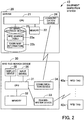
- FIG. 2 is a conceptual diagram illustrating an exemplary configuration of an equipment inspection system according to a second embodiment.
- FIG. 3 is a conceptual diagram illustrating an exemplary RFID search table stored in the server.
- FIG. 4 is a conceptual diagram illustrating an exemplary cabin map information illustrating equipment of an airliner stored in the server.
- An equipment inspection system 10 has a server 20 and an RFID tag search device 30 as illustrated in FIG. 2 .
- the server 20 configured in a computer system, includes a CPU (Central Processing Unit) 21 functioning as the main processor, the CPU 21 being connected to a memory 22, an external storage device 23, and a communication device 24, respectively.
- a CPU Central Processing Unit
- OS Operating System
- application programs to be executed by the CPU 21, as well as data to be used when executing the application programs.
- the external storage device 23 stores, besides the OS and the application programs, an RFID search table 23a and cabin map information 23b.
- the RFID search table 23a and the cabin map information 23b are preliminarily prepared for each type or each body of airliner.
- the communication device 24, having a wireless information communication function, is used when performing wireless information communication with the RFID tag search device 30.
- the RFID tag search device 30 a so-called inspection terminal (handheld terminal: HHT), is a mobile terminal device confgured with a compact computer system.
- the RFID tag search device 30 may be a dedicated HHT, or a tablet terminal having a built-in general-purpose communication function and configured to function as an HHT by software.
- the RFID tag search device 30 includes a CPU 31, the CPU 31 having a memory 32, a reader-writer device 33, a communication device 34, a display device 35, and an input device 36 respectively connected thereto.
- the CPU 31, being configured to control the RFID tag search device 30 as a whole, executes some of the OS programs and an application program for searching the RFID tags, which are loaded in the main storage area of the memory 32.
- the memory 32 includes a memory used as the main storage, and a nonvolatile memory such as a flash memory.
- the memory as the main storage temporarily stores the OS and the application program for searching the RFID tags to be executed by the CPU 31, the RFID search table 23a and the cabin map information 23b downloaded from the server 20, data to be used when executing application programs, or the like.
- the nonvolatile memory stores the OS, the application program for searching the RFID tags, and the like.
- the reader-writer device 33 performs a process of recognizing RFID tags 40a to 40n by exchanging information by short distance wireless communication in the UHF (Ultra High Frequency) band with the RFID tags 40a to 40n attached to items of equipment to be inspected.
- UHF Ultra High Frequency
- the communication device 34 performs information communication with the communication device 24 of the server 20.
- the display device 35 may display various information including the cabin map information 23b and tag search errors, or unsearched/searched segments to an operator carrying the RFID tag search device 30.
- the input device 36 is used by the operator to input instructions such as starting a tag search to the RFID tag search device 30.
- the input device 36 may be implemented as an icon placed on a touch panel in a case where the touch panel is configured by combining the display device 35 and a position input device.
- the processing function of the application program for searching RFID tag stored in the memory 32 may be implemented by a computer including the CPU 31 as the main unit.
- the RFID search table 23a stored in the server 20 includes columns for No., equipment name, identifier (equipment type + serial number), equipment type (filter for RFID detection), RFID position, detected flag, necessity of visual inspection, and remarks, as illustrated in FIG. 3 .
- the RFID position column indicating where an item of equipment is provided in the cabin map information 23b illustrated in FIG. 4 , has columns for X- and Y-coordinates in the cabin map information 23b, position segment, and place.
- the cabin map information 23b which is image information of the cabin to be searched, indicates, by X-coordinates and Y-coordinates, positions of a seat 23b1, a utility area 23b2, and an aisle 23b3.
- the cabin map information 23b as a whole is divided into a plurality of position segments 23b4 (the area indicated by (001) - (017) in FIG. 4 ).
- the position segments 23b4 are set based on a range in which the RFID tag search device 30 is allowed to reliably communicate with RFID tags 40a to 40n when the operator stops on the aisle or enters a space in front of a seat on foot.
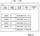
- FIG. 5 illustrates an exemplary content memorized in an RFID tag.
- the RFID tags 40a to 40n each have an EPC as an identifier thereof.
- the EPC has, for example, an EPC length, a maker code, a filter value, a serial No., and a product No.
- the filter value refers to the equipment type used when searching for a specific type of equipment, which corresponds to the equipment type (filter for RFID detection) defined in the RFID search table 23a.
- the RFID tags 40a to 40n each include sessions (numbers S0 S1, S2 and S3) of four different functions used for wireless communication with the reader-writer device 33 of the RFID tag search device 30, and each session has an independent inventoried flag.
- An inventoried flag may take two values A and B, the value of A representing "undetected", i.e., not answered to a tag search by the reader-writer device 33, and the value of B representing "detected", i.e., answered and responsed to a tag search.
- FIG. 6 illustrates an exemplary tag detection sequence
- the tag detection sequence is described taking as an example a case of performing tag detection for two RFID tags 40a and 40b.
- the EPC of the RFID tag 40a is "A001"
- the EPC of the RFID tag 40b is "A002”.
- the letter “A” in the EPC is the equipment type indicating a life vest.
- the numerals "001" and “002" following the equipment type indicate serial Nos., respectively.
- the RFID search table 23a is downloaded from the server 20, and all the tag information of the RFID tags 40a to 40n attached to items of equipment in an airliner is acquired.
- the reader-writer device 33 turns on the carrier. Accordingly, radio wave is emitted from the reader-writer device 33, and the RFID tags 40a and 40b located within a radio wave reachable range enter a Ready state. On this occasion, the inventoried flags included in the RFID tags 40a and 40b respectively are set to "A" indicating an "undetected" state, which is the initial value.
- the reader-writer device 33 issues a Select command specifying, by a parameter, the type of equipment to be searched.
- a parameter "life vest" is specified in the filter as the equipment type. Accordingly, the RFID tags 40a and 40b attached to life vests become effective.
- the reader-writer device 33 issues a Query command specifying a session to be used in wireless communication.
- a session with a session number S3 is specified.
- the RFID tags 40a and 40b Upon receiving the Query command, the RFID tags 40a and 40b transition to an Arbitrate state to avoid collision. In other words, the RFID tags 40a and 40b generate random numbers and set the random numbers to slot counters thereof.
- the reader-writer device 33 repeatedly issues a QueryRep command after having issued the Query command.
- the RFID tags 40a and 40b decrement (-1) the slot counters.
- the RFID tag 40b transitions to a Reply state, generates a 16-bit random number message (RN16) identifying the tag itself, and returns the RN16.
- RN16 16-bit random number message
- the reader-writer device 33 which has received the RN16 transmits an ACK command including the RN16.
- the RFID tag 40b approves occupation of the session S3, and transitions to an Acknowledged state from the Reply state.
- the RFID tag 40b transmits the identifier EPC and sets the inventoried flag of the session S3 to "detected". Note that, although the RFID tag 40b in the Acknowledged state transitions to a Ready state upon receiving the QueryRep command, the inventoried flag is held "detected" without answering to the reader-writer device 33.
- the RFID tag 40a with the EPC being "A001", indicating uncompleted transmission of the EPC performs the same operation as the operation of the RFID tag 40a described above.
- the reader-writer device 33 recognizes that there are two RFID tags 40a and 40b whose EPCs are "A001" and "A002", as RFID tags to be searched for from the RFID search table 23a. Therefore, even when the EPC transmitted from the RFID tag 40b has failed to be normally received due to a communication error or the like, as illustrated in FIG. 6 , the reader-writer device 33 may know the existence of the unreceived RFID tag 40b. In other words, the reader-writer device 33 may identify the RFID tag 40b supposed to be existing by comparing the tag information including the received EPC with the tag information in the RFID search table 23a.
- the RFID tag 40b having set the inventoried flag to "detected" will not answer to the QueryRep command from the reader-writer device 33.
- the inventoried flag which has been set to "detected” is forcibly set to "undetected” by the reader-writer device 33.
- the RFID tag 40b that failed to receive the EPC has been identified from the RFID search table 23a and therefore the RFID tag 40b is directly specified and accessed.
- a Select command is used, specifying, as parameters, the EPC for the filter, the session "S3" for the Target, and "A" for the Action indicating "undetected". Accordingly, the inventoried flag which has been set to "detected" in the session S3 will be forcibly set to "undetected".
- the reader-writer device 33 becomes able to find a tag failed to be searched for by performing in the inventory round 2 a sequence similar to that in the inventory round 1 for RFID tags that have failed to receive the EPC.
- the inventoried flag is forcibly set to "undetected" as a method of disabling the double-read prevention function in the aforementioned example
- the present disclosure is not limited thereto.
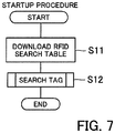
- FIG. 7 is a flowchart illustrating a startup procedure.
- FIG. 8 is a flowchart illustrating a tag search procedure.
- FIG. 9 is a flowchart illustrating a position segment calculation procedure.
- FIG. 10 is a flowchart illustrating an all- items-of-equipment search procedure in a position segment, and
- FIG. 11 illustrates an exemplary error table.
- the CPU 31 downloads, as illustrated in FIG. 7 , the RFID search table 23a and the cabin map information 23b from the server 20 using the communication device 34 (step S11).
- the RFID search table 23a and the cabin map information 23b downloaded from the server 20 are stored in the memory 32, and the cabin map information 23b is displayed on the display device 35.
- the CPU 31 activates the reader-writer device 33 and searches for the RFID tags 40a to 40n (step S12).
- the CPU 31 first calculates, as illustrated in FIG. 8 , a position segment indicating where the operator carrying the RFID tag search device 30 is located in the airplane (step S21).
- the CPU 31 searches for all the items of equipment provided in the calculated position segment (step S22).
- the CPU 31 determines whether or not the search in all the position segments in the airplane has been completed (step S23). When the search in all the position segments in the airplane has not yet completed, the CPU 31 returns to step S21, or the tag search procedure is terminated when the search in all the position segments in the airplane has been completed.
- the CPU 31 first sets the type of equipment to be searched, as illustrated in FIG. 9 (step S31). Although any equipment type may be set as long as the equipment type is defined in the RFID search table 23a, a predetermined default value is set here.
- the CPU 31 performs a tag search specifying the set equipment type (step S32).
- the set equipment type is "life vest”
- a tag search is performed using a Select command with "life vest” being specified as the filter of the parameter.
- the CPU 31 determines whether or not an RFID tag attached to an item of equipment of the set type has been detected within a predetermined time (step S33). The determination of whether or not the RFID tag has been detected is based on whether or not an EPC has been received. On this occasion, the CPU 31 sets the detected flag of the detected RFID tag to "detected" in the RFID search table 23a.
- the CPU 31 obtains the RFID position where the detected RFID tag is provided referring to the RFID search table 23a based on the received EPC, and calculates the position segment from the RFID position (step S34).
- the CPU 31 detects an RFID tag attached to an item of equipment of another type. In other words, the CPU 31 determines whether or not all the types of equipment have been searched (step S35) and, when there exists an unsearched equipment type, sets another equipment type (step S36), and returns to the process at step S32. Upon determining at step S35 that all the types of equipment have been searched, the CPU 31 determines that the operator does not stay in the set position segment, waits for a predetermined time after having displayed on the display device 35 a message prompting to move to another position (step S37), and returns to the process at step S31.
- the CPU 31 first sets the equipment type, as illustrated in FIG. 10 (step S41). With regard to the setting, a predetermined default value may be set, or any of the types of equipment defined in the RFID search table 23a may be acquired and set.
- the CPU 31 determines whether or not the search for all the types of equipment has been completed (step S43).
- the CPU 31 changes the corresponding position segment in the cabin map information 23b being displayed on the display device 35 to a color indicating completion of inspection (step S44), returns to the process of FIG. 8 and proceeds to step S23.
- the change of color of the position segment is performed by overlaying a figure of a specific color on the corresponding position segment in the cabin map information 23b.
- the CPU 31 When, at step S43, the search for all the types of equipment has not been completed, the CPU 31 performs a search specifying the set equipment type (step S45), and determines whether or not there exists an RFID tag detected within a predetermined time (step S46). When no RFID tag has been detected within a predetermined time at step S46, the CPU 31 sets another equipment type (step S47), and returns to the process at step S43.
- the CPU 31 sets the detected flag of all the newly detected RFID tags to "detected" in the RFID search table 23a (step S48).
- the CPU 31 compares the newly detected RFID tags with RFID tags existing in the same position segment, referring to the RFID search table 23a (step S49).
- the CPU 31 determines whether or not there exists an undetected tag supposed to be existing in the same position segment (step S50) and, when there is no undetected tag, sets another equipment type (step S51) and returns to the process at step S43.
- the CPU 31 increments the value of the undetected tag counter (step S52), and determines whether or not the value is equal to or larger than "3" (step S53).
- the CPU 31 acquires the identifier of an undetected tag from the RFID search table 23a (step S54), and attempts to disable the double-read prevention function of the undetected tag by a search using the identifier (step S55).
- the cause of the tag being undetected is a communication error during transmission of the EPC, the inventoried flag is supposed to be changed to "unset”.
- the CPU 31 then returns to the process at step S45 where a search based on the equipment type is performed in the next inventory round.
- step S53 When, at step S53, the value of the tag counter is "3", the value of the tag counter is reset to zero (step S56), the position of the undetected tag is displayed on the display device 35 based on the data of the RFID position of the corresponding undetected tag in the RFID search table 23a, and the operator is prompted to perform visual inspection and also to input the result of the visual inspection using the input device 36 (step S57).
- the CPU 31 determines whether or not the visual inspection has been successful based on the input of the result of visual inspection performed by the operator (step S58).
- the CPU 31 stores the tag failure in an error table (step S59), or stores absence of the item of equipment in the error table when the visual inspection has not been successful (step S60).
- the error table has columns for the type of equipment corresponding to the undetected tag, the error position, the cause of error, or the like, as illustrated in FIG. 11 .
- the CPU 31 stores the corresponding position of the undetected tag in the error table (step S61), sets another equipment type (step S62), and returns to the process at step S43.
- an undetected tag counter is used for counting the number of times attempting to disable the double-read prevention function, there may be provided a button allowing manual switching between disabling and cancelling the disabling of the double-read prevention function, when an undetected tag is found.
Landscapes
- Engineering & Computer Science (AREA)
- Physics & Mathematics (AREA)
- Toxicology (AREA)
- Health & Medical Sciences (AREA)
- Business, Economics & Management (AREA)
- Theoretical Computer Science (AREA)
- General Physics & Mathematics (AREA)
- Human Resources & Organizations (AREA)
- Electromagnetism (AREA)
- General Health & Medical Sciences (AREA)
- Artificial Intelligence (AREA)
- Computer Vision & Pattern Recognition (AREA)
- Tourism & Hospitality (AREA)
- Strategic Management (AREA)
- General Business, Economics & Management (AREA)
- Quality & Reliability (AREA)
- Operations Research (AREA)
- Marketing (AREA)
- Entrepreneurship & Innovation (AREA)
- Economics (AREA)
Abstract
Description
- The embodiments discussed herein relate to a tag detection program, an equipment inspection apparatus, and an equipment inspection method.
- There is known an equipment inspection technique that confirms existence of equipment which may be always equipped with an RFID (Radio Frequency IDentification) tag attached thereto (see, for example, Patent Literature 1).
Patent Literature 1 describes inspecting whether or not there is appropriately provided equipment which is obliged by law or the like to be provided in the cabin of an airliner, such as a life vest supposed to be provided under each seat. Such items of equipment are provided at predetermined positions with RFID tags being preliminarily attached thereto, and a search for RFID tags is performed during preflight inspection. The search for RFID tags is performed using a reader-writer device included in a mobile terminal device such as an HHT (handheld terminal). -
FIG. 12 is an explanatory diagram explaining a general tag detection sequence using a reader-writer device. Note that, for simplicity of explanation of the tag detection operation, explanation of command parameters, the Arbitrate state for avoiding simultaneous responses of a plurality of RFID tags, or the like, is omitted in the explanatory diagram. - When the carrier is turned on by activation of the reader-writer device, an RFID tag located within a radio wave reachable range is powered by the radio wave and enters a Ready state. On this occasion, an inventoried flag provided in the tag enters an "undetected" state which is the initial value of the flag.
- Next, the reader-writer device issues a Select command specifying, by a parameter, the type of equipment to be searched. Accordingly, an RFID tag of the equipment type specified by the parameter is enabled among the RFID tags being in the Ready state.
- Next, the reader-writer device issues a Query command, and an RFID tag which has received the Query command transitions from the Ready state to a Reply state, then generates and transmits a random number message (RN16) for identifying the RFID tag itself.
- Next, upon receiving the random number message, the reader-writer device transmits an ACK (ACKnowledgement) command including the random number message. An RFID tag, upon receiving the ACK command, transitions from the Reply state to an Acknowledged state. In the Acknowledged state, the RFID tag transmits an EPC (Electronic Product Code) which is a unique identifier, and sets the inventoried flag to "detected".
- Then, the reader-writer device, upon receiving the EPC, confirms the existence of the RFID tag having the EPC, and sets "detected" to the tag information of the corresponding RFID tag in a search table storing tag information of RFID tags to be searched for. Accordingly, an item of equipment having attached thereto an RFID tag which has been set "detected" is confirmed to be appropriately provided.
- Here, the RFID tag which transmitted the EPC has the inventoried flag set "detected" and therefore does not respond even when the reader-writer device repeatedly issues a Query command. The detected RFID tag does not respond, and thereby the reader-writer device is prevented from double reading the detected RFID tag, thus simplifying the search process. As a result, it becomes possible to inspect the equipment in the cabin of an airliner efficiently and quickly.
- PTL 1:
Japanese Laid-open Patent Publication No. 2013-209184 - Preventing double reading of an RFID tag is very effective for simplifying the search process. However, when normal transmission of an EPC fails due to a communication error after the transition to the Acknowledged state, a reader-writer device is no longer capable of knowing that the RFID tag has been "detected". In such a case, the reader-writer device is not capable of identifying the RFID tag because the EPC is not notified to the reader-writer device, and therefore visual inspection is also impossible. In addition, the RFID tag returns to the state before the Ready state after a predetermined time has passed since the carrier turned off, and therefore it is possible to wait for the RFID tag to return to such a state and start the search process by the reader-writer device from scratch. In such a case, however, there has been a problem that, even when the RFID tag has returned to the state before the Ready state, the reader-writer device, which is not capable of knowing that the RFID tag has returned to the state before the Ready state, may also detect the "detected" RFID tag.
- An object of the present disclosure which has been made in view of the aforementioned problem is to provide a tag detection program, an equipment inspection apparatus, and an equipment inspection method configured to enable an RFID tag provided with a double-read prevention function to respond in the event of becoming unresponsive after having responded.
- The present disclosure provides, in order to solve the aforementioned problem, a tag detection program for a double-read preventable RFID tag which does not respond to next and subsequent searches after having answered and responded to a search performed by a reader-writer device. The tag detection program causes a computer to perform a procedure including: searching for the RFID tag; making a comparison beween the RFID tag which has answered and responded to the search and tag information in a search table storing the tag information of the RFID tag to be searched for; and when there exists an undetected RFID tag supposed to respond based on the comparison between the RFID tag having responded and the tag information, making an attempt to restore a state of answering and responding to a search with a search specifying the undetected RFID tag, and searching for the undetected RFID tag.
- In addition, the present disclosure provides an equipment inspection apparatus which inspects that there is equipped, at a predetermined position, an item of equipment having attached thereto an RFID tag which turns into a double-read prevented state due to a transition of a flag from an undetected state to a detected state with a search. The equipment inspection apparatus includes: a search table acquisition unit configured to download, from a server, a search table storing correspondence relation between the item of equipment and tag information of the RFID tag attached to the item of equipment; a search table storage unit configured to store the search table acquired by the search table acquisition unit; a tag search unit configured to search for the RFID tag; a comparison processing unit configured to make a comparison bteween the RFID tag having responded after the flag transitioned to a detected state with a search and the tag information in the search table so as to inspect existence of the item of equipment; and a re-search processing unit configured to instruct, when there exists an undetected RFID tag supposed to respond based on the comparison performed by the comparison processing unit, the tag search unit to make an attempt to restore the flag to the undetected state with a search specifying the undetected RFID tag, and search for the undetected RFID tag.
- Furthermore, the present disclosure provides an equipment inspection method for inspecting that there is equipped, at a predetermined position, an item of equipment having attached thereto an RFID tag which turns into a double-read prevented state due to a transition of a flag from an undetected state to a detected state with a search performed by a tag search device. The equipment inspection method includes: downloading, by the tag search device, from a server, a search table storing correspondence relation between the item of equipment and tag information of the RFID tag attached to the item of equipment; searching, by the tag search device, the RFID tag attached to the item of equipment; making, by the tag search device, a comparison between an RFID tag having responded after the flag transitioned to a detected state with a search and tag information in the search table; and when there exists an undetected RFID tag supposed to respond based on the comparison, making an attempt, by the tag search device, to restore the flag to the undetected state with a search specifying the undetected RFID tag, and searching for the undetected RFID tag.
- According to the tag detection program, the equipment inspection apparatus, and the equipment inspection method described above, when there exists an undetected RFID tag supposed to be detected from the search table in a detection of an RFID tag having a double-read prevention function, the double-read prevention function is disabled and re-searching is performed. Accordingly, it has become possible to detect an undetected RFID tag which has been undetectable due to a communication error or the like, despite the existence of the RFID tag.
- The tag detection program, the equipment inspection apparatus, and the equipment inspection method configured as described above are advantageous in that they allow for disabling of the double-read prevention function of an undetected RFID tag supposed to be detected, and therefore the undetected RFID tag is enabled to respond in the event of having become unresponsive during communication.
- The aforementioned and other objects, characteristics and advantages of the present disclosure will be apparent referring to the following description provided in association with the appended drawings illustrating preferred embodiments as examples of the present disclosure.
-
- [
FIG. 1] FIG. 1 is a functional block diagram of an equipment inspection apparatus according to a first embodiment. - [
FIG. 2] FIG. 2 is a conceptual diagram illustrating an exemplary configuration of an equipment inspection system according to a second embodiment. - [
FIG. 3] FIG. 3 is a conceptual diagram illustrating an exemplary RFID search table stored in a server. - [
FIG. 4] FIG. 4 is a conceptual diagram illustrating an exemplary cabin map information illustrating equipment of an airliner stored in the server. - [
FIG. 5] FIG. 5 illustrates an exemplary content memorized in an RFID tag. - [
FIG. 6] FIG. 6 illustrates an exemplary tag detection sequence. - [
FIG. 7] FIG. 7 is a flowchart illustrating a startup procedure. - [
FIG. 8] FIG. 8 is a flowchart illustrating a tag search procedure. - [
FIG. 9] FIG. 9 is a flowchart illustrating a position segment calculation procedure. - [
FIG. 10] FIG. 10 is a flowchart illustrating an all-items-of-equipment search procedure in a position segment. - [
FIG. 11] FIG. 11 illustrates an exemplary error table. - [
FIG. 12] FIG. 12 is an explanatory diagram explaining a general tag detection sequence performed by a reader-writer device. - In the following, embodiments of the present disclosure will be described in detail, referring to the drawing. Note that the respective embodiments may be modified to be implemented by a plurality of embodiments combined together within a consistent range.
-
FIG. 1 is a functional block diagram of an equipment inspection apparatus according to a first embodiment. - An
equipment inspection apparatus 1 includes a searchtable acquisition unit 2, a searchtable storage unit 3, atag search unit 4, acomparison processing unit 5, and are-search processing unit 6. On the other hand, anRFID tag 7 attached to each item of equipment includes anidentifier 8 and aflag 9, theflag 9 having a value reversible from "undetected" to "detected" when responding to a search by theequipment inspection apparatus 1. - The search
table acquisition unit 2 of theequipment inspection apparatus 1 is configured to acquire a search table of tag information describing a list (inventory) ofRFID tags 7 each being attached to a corresponding item of equipment, and the search table is downloaded from a server, for example. - When a search table is acquired by the search
table acquisition unit 2, the searchtable storage unit 3 stores the acquired search table. Thetag search unit 4 searches for theRFID tag 7 through mutual wireless communication with theRFID tag 7. - The
comparison processing unit 5 compares an RFID tag which has responded to a search by thetag search unit 4 with tag information in the search table, and inspects an item of equipment by determining whether or not the item of equipment is provided according to the tag information. Thecomparison processing unit 5 sets "searched" to the search table with regard to the RFID tag which has responded. - The
re-search processing unit 6 operates according to whether or not there remains an undetected RFID tag in the search table as a result of thecomparison processing unit 5 excluding, from the search table, RFID tags which have responded to the search ofRFID tags 7 by thetag search unit 4. In other words, there-search processing unit 6 does nothing when there is no undetected RFID tag remaining in the search table. When, on the other hand, there exists an undetected RFID tag remaining in the search table, there-search processing unit 6 instructs thetag search unit 4 to attempt to return theflag 9 to the undetected state with a search specifying the undetected RFID tag and subsequently search for the undetected RFID tag. - The
comparison processing unit 5 may be notified, by the comparison processing, of an undetected RFID tag supposed to respond, and furthermore, of the identifier of the undetected RFID tag from the tag information in the search table. Thetag search unit 4 notified of an undetected RFID tag and the identifier thereof then forcibly changes the detected tag to "undetected" by directly specifying and accessing the undetected RFID tag. Accordingly, changing theflag 9 of theRFID tag 7 to "undetected" makes it possible for thetag search unit 4 to detect theRFID tag 7 which has been undetected. - Next, description will be provided taking as an example a case where the
equipment inspection apparatus 1 is applied to an RFID tag search device configured to inspect the equipment provided in the cabin of an airliner. The RFID tag search device may be a mobile terminal device functioning as a reader-writer device, and contactless inspection of items of equipment is realized by an inspector walking around the cabin while carrying the mobile terminal device. RFID tags are respectively attached to items of equipment preliminarily provided in the cabin. In addition, it is assumed that detailed information on items of equipment and RFID tags respectively attached to the items of equipment is stored in the server. -
FIG. 2 is a conceptual diagram illustrating an exemplary configuration of an equipment inspection system according to a second embodiment.FIG. 3 is a conceptual diagram illustrating an exemplary RFID search table stored in the server.FIG. 4 is a conceptual diagram illustrating an exemplary cabin map information illustrating equipment of an airliner stored in the server. - An
equipment inspection system 10 according to the second embodiment has aserver 20 and an RFIDtag search device 30 as illustrated inFIG. 2 . - The
server 20, configured in a computer system, includes a CPU (Central Processing Unit) 21 functioning as the main processor, theCPU 21 being connected to amemory 22, anexternal storage device 23, and acommunication device 24, respectively. - The
memory 22, used as a main storage, temporarily stores the OS (Operating System) and application programs to be executed by theCPU 21, as well as data to be used when executing the application programs. - The
external storage device 23 stores, besides the OS and the application programs, an RFID search table 23a andcabin map information 23b. The RFID search table 23a and thecabin map information 23b are preliminarily prepared for each type or each body of airliner. - The
communication device 24, having a wireless information communication function, is used when performing wireless information communication with the RFIDtag search device 30. - On the other hand, the RFID
tag search device 30, a so-called inspection terminal (handheld terminal: HHT), is a mobile terminal device confgured with a compact computer system. The RFIDtag search device 30 may be a dedicated HHT, or a tablet terminal having a built-in general-purpose communication function and configured to function as an HHT by software. - The RFID
tag search device 30 includes aCPU 31, theCPU 31 having amemory 32, a reader-writer device 33, acommunication device 34, adisplay device 35, and aninput device 36 respectively connected thereto. - The
CPU 31, being configured to control the RFIDtag search device 30 as a whole, executes some of the OS programs and an application program for searching the RFID tags, which are loaded in the main storage area of thememory 32. - The
memory 32 includes a memory used as the main storage, and a nonvolatile memory such as a flash memory. The memory as the main storage temporarily stores the OS and the application program for searching the RFID tags to be executed by theCPU 31, the RFID search table 23a and thecabin map information 23b downloaded from theserver 20, data to be used when executing application programs, or the like. The nonvolatile memory stores the OS, the application program for searching the RFID tags, and the like. - The reader-
writer device 33 performs a process of recognizingRFID tags 40a to 40n by exchanging information by short distance wireless communication in the UHF (Ultra High Frequency) band with the RFID tags 40a to 40n attached to items of equipment to be inspected. - The
communication device 34 performs information communication with thecommunication device 24 of theserver 20. - The
display device 35 may display various information including thecabin map information 23b and tag search errors, or unsearched/searched segments to an operator carrying the RFIDtag search device 30. - The
input device 36 is used by the operator to input instructions such as starting a tag search to the RFIDtag search device 30. Note that theinput device 36 may be implemented as an icon placed on a touch panel in a case where the touch panel is configured by combining thedisplay device 35 and a position input device. - With the RFID
tag search device 30 having the aforementioned configuration, the processing function of the application program for searching RFID tag stored in thememory 32 may be implemented by a computer including theCPU 31 as the main unit. - Here, the RFID search table 23a stored in the
server 20 includes columns for No., equipment name, identifier (equipment type + serial number), equipment type (filter for RFID detection), RFID position, detected flag, necessity of visual inspection, and remarks, as illustrated inFIG. 3 . The RFID position column, indicating where an item of equipment is provided in thecabin map information 23b illustrated inFIG. 4 , has columns for X- and Y-coordinates in thecabin map information 23b, position segment, and place. - The
cabin map information 23b, which is image information of the cabin to be searched, indicates, by X-coordinates and Y-coordinates, positions of a seat 23b1, a utility area 23b2, and an aisle 23b3. In addition, thecabin map information 23b as a whole is divided into a plurality of position segments 23b4 (the area indicated by (001) - (017) inFIG. 4 ). The position segments 23b4 are set based on a range in which the RFIDtag search device 30 is allowed to reliably communicate withRFID tags 40a to 40n when the operator stops on the aisle or enters a space in front of a seat on foot. -
FIG. 5 illustrates an exemplary content memorized in an RFID tag. - The RFID tags 40a to 40n each have an EPC as an identifier thereof. The EPC has, for example, an EPC length, a maker code, a filter value, a serial No., and a product No. Here, the filter value refers to the equipment type used when searching for a specific type of equipment, which corresponds to the equipment type (filter for RFID detection) defined in the RFID search table 23a.
- The RFID tags 40a to 40n each include sessions (numbers S0 S1, S2 and S3) of four different functions used for wireless communication with the reader-
writer device 33 of the RFIDtag search device 30, and each session has an independent inventoried flag. In an exchange of command sequences, called an inventory round, only one of the four sessions functions. An inventoried flag may take two values A and B, the value of A representing "undetected", i.e., not answered to a tag search by the reader-writer device 33, and the value of B representing "detected", i.e., answered and responsed to a tag search. -
FIG. 6 illustrates an exemplary tag detection sequence. - For simplicity, the tag detection sequence is described taking as an example a case of performing tag detection for two
RFID tags RFID tag 40a is "A001" and the EPC of theRFID tag 40b is "A002". Note that the letter "A" in the EPC is the equipment type indicating a life vest. The numerals "001" and "002" following the equipment type indicate serial Nos., respectively. - First, in the tag detection sequence, the RFID search table 23a is downloaded from the
server 20, and all the tag information of the RFID tags 40a to 40n attached to items of equipment in an airliner is acquired. - Next, the reader-
writer device 33 turns on the carrier. Accordingly, radio wave is emitted from the reader-writer device 33, and theRFID tags RFID tags - Next, the reader-
writer device 33 issues a Select command specifying, by a parameter, the type of equipment to be searched. Here, a parameter "life vest" is specified in the filter as the equipment type. Accordingly, theRFID tags - Next, the reader-
writer device 33 issues a Query command specifying a session to be used in wireless communication. In the example ofFIG. 6 , a session with a session number S3 is specified. - Upon receiving the Query command, the
RFID tags RFID tags writer device 33 repeatedly issues a QueryRep command after having issued the Query command. Upon receiving the QueryRep command, theRFID tags - Here, when the slot counter of the
RFID tag 40b whose EPC is "A002" reaches zero first, theRFID tag 40b transitions to a Reply state, generates a 16-bit random number message (RN16) identifying the tag itself, and returns the RN16. - Next, the reader-
writer device 33 which has received the RN16 transmits an ACK command including the RN16. Upon receiving the ACK command, theRFID tag 40b approves occupation of the session S3, and transitions to an Acknowledged state from the Reply state. In the Acknowledged state, theRFID tag 40b transmits the identifier EPC and sets the inventoried flag of the session S3 to "detected". Note that, although theRFID tag 40b in the Acknowledged state transitions to a Ready state upon receiving the QueryRep command, the inventoried flag is held "detected" without answering to the reader-writer device 33. - Next, after having received the QueryRep command and the slot counter thereof having reached zero, the
RFID tag 40a with the EPC being "A001", indicating uncompleted transmission of the EPC, performs the same operation as the operation of theRFID tag 40a described above. - The reader-
writer device 33 recognizes that there are twoRFID tags RFID tag 40b has failed to be normally received due to a communication error or the like, as illustrated inFIG. 6 , the reader-writer device 33 may know the existence of theunreceived RFID tag 40b. In other words, the reader-writer device 33 may identify theRFID tag 40b supposed to be existing by comparing the tag information including the received EPC with the tag information in the RFID search table 23a. - As described above, the
RFID tag 40b, having set the inventoried flag to "detected", will not answer to the QueryRep command from the reader-writer device 33. In such a case, the inventoried flag which has been set to "detected" is forcibly set to "undetected" by the reader-writer device 33. - In other words, the
RFID tag 40b that failed to receive the EPC has been identified from the RFID search table 23a and therefore theRFID tag 40b is directly specified and accessed. In the example illustrated inFIG. 6 , a Select command is used, specifying, as parameters, the EPC for the filter, the session "S3" for the Target, and "A" for the Action indicating "undetected". Accordingly, the inventoried flag which has been set to "detected" in the session S3 will be forcibly set to "undetected". - Subsequently, the reader-
writer device 33 becomes able to find a tag failed to be searched for by performing in the inventory round 2 a sequence similar to that in theinventory round 1 for RFID tags that have failed to receive the EPC. - Note that there may be a case where it is impossible to find an
RFID tag 40b which has failed to be searched for by directly specifying theRFID tag 40b which has failed to be searched for and repeatedly attempting to forcibly switch the inventoried flag to "undetected", which has been set to "detected". For example, a case where an item of equipment itself is not equipped, or a case where an item of equipment is equipped but the RFID tag attached to the equipment has been failed. In such a case, it suffices that the operator performs visual inspection of the equipment. - In addition, although the inventoried flag is forcibly set to "undetected" as a method of disabling the double-read prevention function in the aforementioned example, the present disclosure is not limited thereto. For example, it is conceivable to use a session of a different number from the number of the session used for the search in the preceding
inventory round 1 when performing a search specifying the undetected RFID tag to take advantage of the inventoried flag of the session being "undetected". - Next, the operation of the RFID
tag search device 30 will be described, referring to a flowchart. -
FIG. 7 is a flowchart illustrating a startup procedure.FIG. 8 is a flowchart illustrating a tag search procedure.FIG. 9 is a flowchart illustrating a position segment calculation procedure.FIG. 10 is a flowchart illustrating an all- items-of-equipment search procedure in a position segment, andFIG. 11 illustrates an exemplary error table. - When a tag detection program is activated in the RFID
tag search device 30, theCPU 31 downloads, as illustrated inFIG. 7 , the RFID search table 23a and thecabin map information 23b from theserver 20 using the communication device 34 (step S11). The RFID search table 23a and thecabin map information 23b downloaded from theserver 20 are stored in thememory 32, and thecabin map information 23b is displayed on thedisplay device 35. - Next, the
CPU 31 activates the reader-writer device 33 and searches for the RFID tags 40a to 40n (step S12). - In the search process for the RFID tags 40a to 40n, the
CPU 31 first calculates, as illustrated inFIG. 8 , a position segment indicating where the operator carrying the RFIDtag search device 30 is located in the airplane (step S21). - Next, the
CPU 31 searches for all the items of equipment provided in the calculated position segment (step S22). - Next, the
CPU 31 determines whether or not the search in all the position segments in the airplane has been completed (step S23). When the search in all the position segments in the airplane has not yet completed, theCPU 31 returns to step S21, or the tag search procedure is terminated when the search in all the position segments in the airplane has been completed. - Here, details of the process of calculating the position segment at step S21 will be described. In the position segment calculation procedure, the
CPU 31 first sets the type of equipment to be searched, as illustrated inFIG. 9 (step S31). Although any equipment type may be set as long as the equipment type is defined in the RFID search table 23a, a predetermined default value is set here. - Next, the
CPU 31 performs a tag search specifying the set equipment type (step S32). Here, when the set equipment type is "life vest", for example a tag search is performed using a Select command with "life vest" being specified as the filter of the parameter. - Next, the
CPU 31 determines whether or not an RFID tag attached to an item of equipment of the set type has been detected within a predetermined time (step S33). The determination of whether or not the RFID tag has been detected is based on whether or not an EPC has been received. On this occasion, theCPU 31 sets the detected flag of the detected RFID tag to "detected" in the RFID search table 23a. - When an RFID tag has been detected, the
CPU 31 obtains the RFID position where the detected RFID tag is provided referring to the RFID search table 23a based on the received EPC, and calculates the position segment from the RFID position (step S34). - When no RFID tag has been detected at step S33, the
CPU 31 detects an RFID tag attached to an item of equipment of another type. In other words, theCPU 31 determines whether or not all the types of equipment have been searched (step S35) and, when there exists an unsearched equipment type, sets another equipment type (step S36), and returns to the process at step S32. Upon determining at step S35 that all the types of equipment have been searched, theCPU 31 determines that the operator does not stay in the set position segment, waits for a predetermined time after having displayed on the display device 35 a message prompting to move to another position (step S37), and returns to the process at step S31. - When which position segment the operator stays in the airplane is calculated according to the aforementioned process, inspection is next performed for all the items of equipment provided in the position segment. The
CPU 31 first sets the equipment type, as illustrated inFIG. 10 (step S41). With regard to the setting, a predetermined default value may be set, or any of the types of equipment defined in the RFID search table 23a may be acquired and set. - Next, the
CPU 31 initializes an undetected tag counter (step S42). The undetected tag counter counts the number of operation times to set the inventoried flag from "detected" to "undetected" and, when a predetermined number of times is exceeded, terminates the operation, and is set to n = 0 in the initialization. - Next, the
CPU 31 determines whether or not the search for all the types of equipment has been completed (step S43). Here, when the search for all the types of equipment in the position segment has been completed, theCPU 31 changes the corresponding position segment in thecabin map information 23b being displayed on thedisplay device 35 to a color indicating completion of inspection (step S44), returns to the process ofFIG. 8 and proceeds to step S23. The change of color of the position segment is performed by overlaying a figure of a specific color on the corresponding position segment in thecabin map information 23b. - When, at step S43, the search for all the types of equipment has not been completed, the
CPU 31 performs a search specifying the set equipment type (step S45), and determines whether or not there exists an RFID tag detected within a predetermined time (step S46). When no RFID tag has been detected within a predetermined time at step S46, theCPU 31 sets another equipment type (step S47), and returns to the process at step S43. - When, at step S46, at least one RFID tag has been detected within a predetermined time, the
CPU 31 sets the detected flag of all the newly detected RFID tags to "detected" in the RFID search table 23a (step S48). Next, theCPU 31 compares the newly detected RFID tags with RFID tags existing in the same position segment, referring to the RFID search table 23a (step S49). - Next, the
CPU 31 determines whether or not there exists an undetected tag supposed to be existing in the same position segment (step S50) and, when there is no undetected tag, sets another equipment type (step S51) and returns to the process at step S43. - When it is determined at step S50 that there exists an undetected tag, the
CPU 31 increments the value of the undetected tag counter (step S52), and determines whether or not the value is equal to or larger than "3" (step S53). When the value of the tag counter is smaller than "3", theCPU 31 acquires the identifier of an undetected tag from the RFID search table 23a (step S54), and attempts to disable the double-read prevention function of the undetected tag by a search using the identifier (step S55). Here, when the cause of the tag being undetected is a communication error during transmission of the EPC, the inventoried flag is supposed to be changed to "unset". TheCPU 31 then returns to the process at step S45 where a search based on the equipment type is performed in the next inventory round. - When, at step S53, the value of the tag counter is "3", the value of the tag counter is reset to zero (step S56), the position of the undetected tag is displayed on the
display device 35 based on the data of the RFID position of the corresponding undetected tag in the RFID search table 23a, and the operator is prompted to perform visual inspection and also to input the result of the visual inspection using the input device 36 (step S57). On this occasion, it is preferred to display the seat number and the place where the item of equipment is provided (e.g., under the seat for adult life vest) calculated from the X- and Y-coordinates, rather than displaying the position of the undetected tag on thedisplay device 35 in terms of X- and Y-coordinates. - Next, the
CPU 31 determines whether or not the visual inspection has been successful based on the input of the result of visual inspection performed by the operator (step S58). Here, when the visual inspection has been successful, theCPU 31 stores the tag failure in an error table (step S59), or stores absence of the item of equipment in the error table when the visual inspection has not been successful (step S60). The error table has columns for the type of equipment corresponding to the undetected tag, the error position, the cause of error, or the like, as illustrated inFIG. 11 . - When processes at steps S59 and S60 are completed, the
CPU 31 stores the corresponding position of the undetected tag in the error table (step S61), sets another equipment type (step S62), and returns to the process at step S43. - Although the number of times attempting to disable the double-read prevention function of an undetected tag when there exists an undetected tag has been set to two at most in the aforementioned flowchart, the present disclosure is not limited thereto. In addition, although an undetected tag counter is used for counting the number of times attempting to disable the double-read prevention function, there may be provided a button allowing manual switching between disabling and cancelling the disabling of the double-read prevention function, when an undetected tag is found.
- The foregoing merely describes the principle of the present disclosure. Furthermore, it is to be noted that while various variations and modifications may be made by those skilled in the art, the present disclosure is not limited to the exact configurations and applications illustrated and described above, and that all the corresponding variations and equivalents thereof are within the range of the present disclosure according to the appended claims and equivalents thereof.
-
- 1
- equipment inspection apparatus
- 2
- search table acquisition unit
- 3
- search table storage unit
- 4
- tag search unit
- 5
- comparison processing unit
- 6
- re-search processing unit
- 7
- RFID tag
- 8
- identifier
- 9
- flag
- 10
- equipment inspection system
- 20
- server
- 21
- CPU
- 22
- memory
- 23
- external storage device
- 23a
- RFID search table
- 23b
- cabin map information
- 23b1
- seat
- 23b2
- utility area
- 23b3
- aisle
- 23b4
- position segment
- 24
- communication device
- 30
- RFID tag search device
- 31
- CPU
- 32
- memory
- 33
- reader-writer device
- 34
- communication device
- 35
- display device
- 36
- input device
- 40a - 40n
- RFID tag
Claims (8)
- A tag detection program for a double-read preventable RFID tag which does not respond to next and subsequent searches after having answered and responded to a search performed by a reader-writer device, the tag detection program causing a computer to perform a procedure comprising:searching for the RFID tag;making a comparison bewteen the RFID tag which has answered and responded to the search and tag information in a search table storing the tag information of the RFID tag to be searched for; andwhen there exists an undetected RFID tag supposed to respond based on the comparison between the RFID tag having responded and the tag information, making an attempt to restore a state of answering and responding to a search with a search specifying the undetected RFID tag, and searching for the undetected RFID tag.
- The tag detection program according to claim 1, wherein, as the attempt to restore a state of answering and responding to a search, the procedure further includes forcibly setting an inventoried flag to "undetected", the inventoried flag having an initial value of "undetected" and being set to "detected" when answering and responding to a search are made.
- The tag detection program according to claim 1, wherein, as the attempt to restore a state of answering and responding to a search, the procedure further includes using a session of a number different from a number of a session used for a search in a preceding inventory round when performing a search specifying the undetected RFID tag.
- The tag detection program according to claim 1, wherein the procedure further includes displaying an error on a display screen and storing the error in an error table when there is no response from the undetected RFID tag despite that the search for the undetected RFID tag has been repeated for a predetermined number of times.
- The tag detection program according to claim 1, wherein, an entire area in which items of equipment each having the RFID tag attached thereto are provided is divided into a plurality of position segments, the search table stores therein information on which one of the position segments the RFID tag belongs to, and the procedure further includes making the comparison between the RFID tag having responded and the tag information for each of the position segments.
- The tag detection program according to claim 5, wherein, in a case where RFID tags to be searched for are attached to the items of equipment according to a plurality of equipment types, the procedure further includes switching to a search for RFID tags of another equipment type upon completion of a search for RFID tags of a certain equipment type in a certain position segment, and terminates the search for RFID tags in the certain position segment upon completion of searches for the RFID tags of all the equipment types.
- An equipment inspection apparatus which inspects that there is equipped, at a predetermined position, an item of equipment having attached thereto an RFID tag which turns into a double-read prevented state due to a transition of a flag from an undetected state to a detected state with a search, the apparatus comprising:a search table acquisition unit configured to download, from a server, a search table storing a correspondence relation between the item of equipment and tag information of the RFID tag attached to the item of equipment;a search table storage unit configured to store the search table acquired by the search table acquisition unit;a tag search unit configured to search for the RFID tag;a comparison processing unit configured to make a comparison between the RFID tag having responded after the flag transitioned to a detected state with a search and the tag information in the search table so as to inspect existence of the item of equipment; anda re-search processing unit configured to instruct, when there exists an undetected RFID tag supposed to respond based on the comparison performed by the comparison processing unit, the tag search unit to make an attempt to restore the flag to the undetected state with a search specifying the undetected RFID tag, and search for the undetected RFID tag.
- An equipment inspection method for inspecting that there is equipped, at a predetermined position, an item of equipment having attached thereto an RFID tag which turns into a double-read prevented state due to a transition of a flag from an undetected state to a detected state with a search performed by a tag search device, the method comprising:downloading, by the tag search device, from a server, a search table storing a correspondence relation between the item of equipment and tag information of the RFID tag attached to the item of equipment;searching, by the tag search device, for the RFID tag attached to the item of equipment;making, by the tag search device, a comparison between an RFID tag having responded after the flag transitioned to a detected state with a search and tag information in the search table; andwhen there exists an undetected RFID tag supposed to respond based on the comparison, making an attempt, by the tag search device, to restore the flag to the undetected state with a search specifying the undetected RFID tag, and searching for the undetected RFID tag.
Applications Claiming Priority (1)
| Application Number | Priority Date | Filing Date | Title |
|---|---|---|---|
| PCT/JP2014/070169 WO2016016986A1 (en) | 2014-07-31 | 2014-07-31 | Tag detection program, equipment inspection device and equipment inspection method |
Publications (2)
| Publication Number | Publication Date |
|---|---|
| EP3176724A1 true EP3176724A1 (en) | 2017-06-07 |
| EP3176724A4 EP3176724A4 (en) | 2017-10-11 |
Family
ID=55216927
Family Applications (1)
| Application Number | Title | Priority Date | Filing Date |
|---|---|---|---|
| EP14899002.1A Withdrawn EP3176724A4 (en) | 2014-07-31 | 2014-07-31 | Tag detection program, equipment inspection device and equipment inspection method |
Country Status (4)
| Country | Link |
|---|---|
| US (1) | US9886603B2 (en) |
| EP (1) | EP3176724A4 (en) |
| JP (1) | JP6064090B2 (en) |
| WO (1) | WO2016016986A1 (en) |
Families Citing this family (8)
| Publication number | Priority date | Publication date | Assignee | Title |
|---|---|---|---|---|
| ITTO20110839A1 (en) * | 2011-09-20 | 2013-03-21 | Sisvel Technology Srl | METHOD FOR RECONSTRUCTION OF THE PLANT OF AN ENVIRONMENT SURROUNDING A WIRELESS DEVICE AND WIRELESS DEVICE THAT IMPLEMENTS THIS METHOD |
| WO2018152098A1 (en) * | 2017-02-14 | 2018-08-23 | Systems And Software Enterprises, Llc | Apparatus, systems, and methods for life vest identification, inspection, and maintenance |
| DE112018000705T5 (en) | 2017-03-06 | 2019-11-14 | Cummins Filtration Ip, Inc. | DETECTION OF REAL FILTERS WITH A FILTER MONITORING SYSTEM |
| US10460137B1 (en) * | 2018-02-07 | 2019-10-29 | Amazon Technologies, Inc. | Dynamic RFID tag singulation using state information masking |
| FR3088621B1 (en) * | 2018-11-16 | 2021-01-08 | Safran Electronics & Defense | PROCEDURE FOR VERIFYING THE PRESENCE OF EQUIPMENT ON BOARD AN AIRCRAFT AND ASSOCIATED DEVICE |
| JP7278140B2 (en) * | 2019-04-23 | 2023-05-19 | 東芝テック株式会社 | Wireless tag reader and program |
| JP7633829B2 (en) * | 2021-02-22 | 2025-02-20 | 東芝テック株式会社 | Wireless tag reader and program |
| CN112836777B (en) * | 2021-03-02 | 2022-09-27 | 同济大学 | Application method of consensus initiative mechanism in target search of swarm robots |
Family Cites Families (12)
| Publication number | Priority date | Publication date | Assignee | Title |
|---|---|---|---|---|
| JPH0920410A (en) | 1995-07-06 | 1997-01-21 | Sekisui Chem Co Ltd | Container control device |
| US20090267747A1 (en) * | 2003-03-31 | 2009-10-29 | Rivest Ronald L | Security and Data Collision Systems and Related Techniques for Use With Radio Frequency Identification Systems |
| JP4378474B2 (en) | 2003-07-04 | 2009-12-09 | 国立大学法人九州大学 | Article management system and article management method |
| US8102244B2 (en) | 2003-08-09 | 2012-01-24 | Alien Technology Corporation | Methods and apparatuses to identify devices |
| JP4239033B2 (en) * | 2004-06-15 | 2009-03-18 | ブラザー工業株式会社 | Interrogator for RFID tag communication system |
| US7142120B2 (en) * | 2004-06-29 | 2006-11-28 | Symbol Technologies, Inc. | Item finding using RF signalling |
| TWI325122B (en) * | 2006-12-04 | 2010-05-21 | Ind Tech Res Inst | Method and system for reading and identifying rfid tag |
| WO2008081551A1 (en) * | 2006-12-28 | 2008-07-10 | Mitsubishi Electric Corporation | Reader, calling device, id reading program, and id reading method |
| JP4716195B2 (en) | 2007-10-17 | 2011-07-06 | ブラザー工業株式会社 | Wireless tag communication device |
| JP5157793B2 (en) * | 2008-09-30 | 2013-03-06 | パナソニック株式会社 | RFID system |
| JP2011028470A (en) | 2009-07-24 | 2011-02-10 | Brother Industries Ltd | Radio tag reader and conveyance object management system |
| JP5744785B2 (en) * | 2012-03-30 | 2015-07-08 | 富士通フロンテック株式会社 | Article inspection method, portable terminal device, control program for portable terminal device, and article search system |
-
2014
- 2014-07-31 JP JP2016537668A patent/JP6064090B2/en not_active Expired - Fee Related
- 2014-07-31 EP EP14899002.1A patent/EP3176724A4/en not_active Withdrawn
- 2014-07-31 WO PCT/JP2014/070169 patent/WO2016016986A1/en not_active Ceased
-
2016
- 2016-10-26 US US15/334,969 patent/US9886603B2/en not_active Expired - Fee Related
Also Published As
| Publication number | Publication date |
|---|---|
| JPWO2016016986A1 (en) | 2017-04-27 |
| JP6064090B2 (en) | 2017-01-18 |
| WO2016016986A1 (en) | 2016-02-04 |
| EP3176724A4 (en) | 2017-10-11 |
| US9886603B2 (en) | 2018-02-06 |
| US20170046543A1 (en) | 2017-02-16 |
Similar Documents
| Publication | Publication Date | Title |
|---|---|---|
| EP3176724A1 (en) | Tag detection program, equipment inspection device and equipment inspection method | |
| US11800317B1 (en) | Context based action menu | |
| US20210390106A1 (en) | Automated annotation system for electronic logging devices | |
| US10810412B2 (en) | Method, system and apparatus for gesture-based configuration of paired scanner | |
| US10671373B1 (en) | Mechanism for automatically incorporating software code changes into proper channels | |
| EP3287922A1 (en) | Unlocking control method and terminal device | |
| EP3740948B1 (en) | Automated inspection and part enrollment | |
| WO2023009206A1 (en) | Automatically generating one or more machine vision jobs based on region of interests (rois) of digital images | |
| EP3182651A1 (en) | Method of controlling operation of cataloged smart devices | |
| JP6380408B2 (en) | Mobile device and method for establishing a wireless link | |
| JP2014146173A (en) | Article position detection system, article position detection device, article position detection method and program | |
| CN111356169B (en) | Mobile terminal test device and test case extraction method thereof | |
| US20180082034A1 (en) | Surgical kit tracking control device | |
| KR20160104246A (en) | Unmanned inventory actual inspection system using arerial vehicle and the method thereof | |
| CN113220322A (en) | Test software updating method, electronic device and storage medium | |
| CN109352657B (en) | Control method, related device and storage medium | |
| US20180135991A1 (en) | Indoor navigation system and indoor navigation method | |
| JP2022011868A (en) | Position detection system, position detection method, information processing device, and program | |
| CN109450966B (en) | Equipment positioning method and device, computer equipment and storage medium | |
| CN114677049A (en) | Testing equipment process testing method, device, computer equipment | |
| US12475338B2 (en) | Wireless tag reading apparatus, method, and storage medium | |
| CN109636279A (en) | Material detection method, device, electronic equipment and storage medium | |
| EP3413209A1 (en) | Method and system for detecting width of touch pattern and identifying touch pattern | |
| CN112449300A (en) | Method and device for updating position information, storage medium and electronic device | |
| CN110237524B (en) | Method and related device for determining object placement pattern |
Legal Events
| Date | Code | Title | Description |
|---|---|---|---|
| 17P | Request for examination filed |
Effective date: 20161017 |
|
| AK | Designated contracting states |
Kind code of ref document: A1 Designated state(s): AL AT BE BG CH CY CZ DE DK EE ES FI FR GB GR HR HU IE IS IT LI LT LU LV MC MK MT NL NO PL PT RO RS SE SI SK SM TR |
|
| AX | Request for extension of the european patent |
Extension state: BA ME |
|
| PUAI | Public reference made under article 153(3) epc to a published international application that has entered the european phase |
Free format text: ORIGINAL CODE: 0009012 |
|
| A4 | Supplementary search report drawn up and despatched |
Effective date: 20170912 |
|
| RIC1 | Information provided on ipc code assigned before grant |
Ipc: G06K 7/10 20060101AFI20170906BHEP Ipc: G06Q 10/00 20120101ALI20170906BHEP |
|
| DAX | Request for extension of the european patent (deleted) | ||
| 17Q | First examination report despatched |
Effective date: 20180116 |
|
| STAA | Information on the status of an ep patent application or granted ep patent |
Free format text: STATUS: THE APPLICATION IS DEEMED TO BE WITHDRAWN |
|
| 18D | Application deemed to be withdrawn |
Effective date: 20191203 |