EP3176618A1 - Optical device and optical device manufacturing method - Google Patents
Optical device and optical device manufacturing method Download PDFInfo
- Publication number
- EP3176618A1 EP3176618A1 EP15828316.8A EP15828316A EP3176618A1 EP 3176618 A1 EP3176618 A1 EP 3176618A1 EP 15828316 A EP15828316 A EP 15828316A EP 3176618 A1 EP3176618 A1 EP 3176618A1
- Authority
- EP
- European Patent Office
- Prior art keywords
- jacket
- cladding
- section
- optical device
- optical fiber
- Prior art date
- Legal status (The legal status is an assumption and is not a legal conclusion. Google has not performed a legal analysis and makes no representation as to the accuracy of the status listed.)
- Withdrawn
Links
- 230000003287 optical effect Effects 0.000 title claims abstract description 99
- 238000004519 manufacturing process Methods 0.000 title 1
- 238000005253 cladding Methods 0.000 claims abstract description 171
- 239000011347 resin Substances 0.000 claims abstract description 110
- 229920005989 resin Polymers 0.000 claims abstract description 110
- 239000013307 optical fiber Substances 0.000 claims abstract description 82
- 238000000034 method Methods 0.000 claims description 15
- 239000013598 vector Substances 0.000 claims description 11
- 239000011521 glass Substances 0.000 claims description 3
- 239000000835 fiber Substances 0.000 description 12
- 230000000694 effects Effects 0.000 description 5
- 230000012447 hatching Effects 0.000 description 4
- NCGICGYLBXGBGN-UHFFFAOYSA-N 3-morpholin-4-yl-1-oxa-3-azonia-2-azanidacyclopent-3-en-5-imine;hydrochloride Chemical compound Cl.[N-]1OC(=N)C=[N+]1N1CCOCC1 NCGICGYLBXGBGN-UHFFFAOYSA-N 0.000 description 1
- 239000011248 coating agent Substances 0.000 description 1
- 238000000576 coating method Methods 0.000 description 1
- 230000003247 decreasing effect Effects 0.000 description 1
- 238000010438 heat treatment Methods 0.000 description 1
- 238000003825 pressing Methods 0.000 description 1
- 230000000644 propagated effect Effects 0.000 description 1
- 239000007787 solid Substances 0.000 description 1
Images



Classifications
-
- G—PHYSICS
- G02—OPTICS
- G02B—OPTICAL ELEMENTS, SYSTEMS OR APPARATUS
- G02B6/00—Light guides; Structural details of arrangements comprising light guides and other optical elements, e.g. couplings
- G02B6/02—Optical fibres with cladding with or without a coating
- G02B6/02395—Glass optical fibre with a protective coating, e.g. two layer polymer coating deposited directly on a silica cladding surface during fibre manufacture
-
- G—PHYSICS
- G02—OPTICS
- G02B—OPTICAL ELEMENTS, SYSTEMS OR APPARATUS
- G02B6/00—Light guides; Structural details of arrangements comprising light guides and other optical elements, e.g. couplings
- G02B6/02—Optical fibres with cladding with or without a coating
- G02B6/036—Optical fibres with cladding with or without a coating core or cladding comprising multiple layers
- G02B6/03616—Optical fibres characterised both by the number of different refractive index layers around the central core segment, i.e. around the innermost high index core layer, and their relative refractive index difference
- G02B6/03622—Optical fibres characterised both by the number of different refractive index layers around the central core segment, i.e. around the innermost high index core layer, and their relative refractive index difference having 2 layers only
-
- G—PHYSICS
- G02—OPTICS
- G02B—OPTICAL ELEMENTS, SYSTEMS OR APPARATUS
- G02B6/00—Light guides; Structural details of arrangements comprising light guides and other optical elements, e.g. couplings
- G02B6/24—Coupling light guides
- G02B6/42—Coupling light guides with opto-electronic elements
- G02B6/4296—Coupling light guides with opto-electronic elements coupling with sources of high radiant energy, e.g. high power lasers, high temperature light sources
-
- G—PHYSICS
- G02—OPTICS
- G02B—OPTICAL ELEMENTS, SYSTEMS OR APPARATUS
- G02B6/00—Light guides; Structural details of arrangements comprising light guides and other optical elements, e.g. couplings
- G02B6/02—Optical fibres with cladding with or without a coating
- G02B6/036—Optical fibres with cladding with or without a coating core or cladding comprising multiple layers
- G02B6/03605—Highest refractive index not on central axis
-
- G—PHYSICS
- G02—OPTICS
- G02B—OPTICAL ELEMENTS, SYSTEMS OR APPARATUS
- G02B6/00—Light guides; Structural details of arrangements comprising light guides and other optical elements, e.g. couplings
- G02B6/10—Light guides; Structural details of arrangements comprising light guides and other optical elements, e.g. couplings of the optical waveguide type
- G02B6/14—Mode converters
Definitions
- the present invention relates to an optical device including (i) an optical fiber in which a jacket-removed section is provided and (ii) a resin member in which the jacket-removed section is embedded.
- the present invention also relates to a method of producing such an optical device.
- Optical fibers such as double cladding fibers and triple cladding fibers, in which light can be confined to a cladding, are in wide use.
- unnecessary light that propagates in a cladding (hereinafter referred to as "cladding light”) may cause heating in a jacket which covers an outer surface of the cladding.
- cladding light unnecessary light that propagates in a cladding
- Patent Literature 1 discloses an optical device including (i) an optical fiber in which a jacket-removed section is provided (jacket is referred to as a "pre-coating" in Patent Literature 1) and (ii) a resin member in which the jacket-removed section is embedded.
- a refractive index of the resin member is set to be higher than that of a cladding so that cladding light will leak from the cladding into the resin member through the jacket-removed section.
- Patent Literature 1 Japanese Patent Application Publication Tokukaihei No. 1-316705 (1989) (Publication Date: December 21, 1989 )
- the present invention has been accomplished in view of the above problem, and an object of an aspect of the present invention is to provide an optical device (i) which includes (a) an optical fiber in which a jacket-removed section is provided and (b) a resin member in which the jacket-removed section is embedded and (ii) in which the resin member is less likely to reach a high temperature, as compared with that of a conventional optical device.
- an optical device in accordance with an aspect of the present invention includes: an optical fiber in which at least one jacket-removed section is provided; and a resin member in which the at least one jacket-removed section of the optical fiber is embedded, the resin member having a refractive index higher than a refractive index of a cladding of the optical fiber, the at least one jacket-removed section being a section in which a jacket covering an outer surface of the cladding has been partially removed so that only a part of the outer surface of the cladding is exposed in a cross section of the optical fiber.
- a method of producing an optical fiber in accordance with an aspect of the present invention includes the steps of: forming a jacket-removed section in an optical fiber; and embedding the jacket-removed section of the optical fiber in a resin member having a refractive index higher than a refractive index of a cladding of the optical fiber, the jacket-removed section being a section in which a jacket covering an outer surface of the cladding has been partially removed so that only a part of the outer surface of the cladding is exposed in a cross section of the optical fiber.
- the present invention makes it possible to provide an optical device in which a resin member is less likely to reach a high temperature, as compared with that of a conventional optical device.
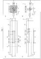
- FIG. 1 A configuration of an optical device 1 in accordance with the present embodiment will be discussed below with reference to Fig. 1 .
- (a) of Fig. 1 is a top view of the optical device 1
- (b) of Fig. 1 is a lateral view of the optical device 1
- (c) of Fig. 1 is an A-A' sectional view of the optical device 1
- (d) of Fig. 1 is a B-B' sectional view (in which hatching is omitted) of the optical device 1.
- the optical device 1 includes (i) an optical fiber 11 in which a jacket-removed section I1 is provided and (ii) a resin member 12 in which the jacket-removed section I1 of the optical fiber 11 is embedded.
- the optical fiber 11, which is a double cladding fiber includes (i) a core 111a having a columnar shape, (ii) an inner cladding 111b having a cylindrical shape and covering a side surface of the core 111a, (iii) an outer cladding 112a having a cylindrical shape and covering an outer surface of the inner cladding 111b, and (iv) an outer jacket 112b having a cylindrical shape and covering an outer surface of the outer cladding 112a (see (c) of Fig. 1 ).
- each of the core 111a and the inner cladding 111b is made of glass.
- the core 111a and the inner cladding 111b will be hereinafter collectively referred to as a bare fiber 111.
- each of the outer cladding 112a and the outer jacket 112b is made of resin.
- the outer cladding 112a and the outer jacket 112b will be hereinafter collectively referred to as a jacket 112.
- the jacket-removed section I1 of the optical fiber 11 is a section in which the jacket 112, which covers the outer surface of the inner cladding 111b, has been partially removed so that a part of the outer surface of the inner cladding 111b is exposed in a cross section (i.e., a section orthogonal to a central axis of the optical fiber 11).
- a part of the jacket 112 is removed in the jacket-removed section I1 and adjacent sections 12 and 13, each of which is adjacent to the jacket-removed section I1, such that a projection of the part thus removed forms a trapezoid on a y-z plane (see (b) of Fig. 1 ).
- a cut surface 112c1 of the jacket 112 in the jacket-removed section I1 is therefore a rectangular flat surface having a normal vector v1 which is parallel to a radial direction of the optical fiber 11 (i.e., a y-axis positive direction illustrated in Fig. 1 ) (see (a) and (b) of Fig. 1 ).
- Cut surfaces 112c2 and 112c3 of the jacket 112 in the respective adjacent sections 12 and 13 are semi-elliptical flat surfaces having respective normal vectors v2 and v3, each of which makes an angle smaller than ⁇ /2[rad] with the radial direction of the optical fiber 11 (i.e., the y-axis positive direction illustrated in Fig. 1 ) (see (a) and (b) of Fig. 1 ).
- the jacket 112 is removed in the jacket-removed section I1 by a depth d, which is greater than a thickness t' of the jacket 112 (i.e., a sum of thicknesses of the outer cladding 112a and the outer jacket 112b) (see (b) of Fig. 1 ). Therefore, in the cross section of the jacket-removed section I1, a part of the outer surface of the inner cladding 111b is exposed within a range of ⁇ [rad] from the y-axis positive direction without being covered with the jacket 112 (see (d) of Fig. 1 ).
- the jacket-removed section I1 of the optical fiber 11 is embedded in the resin member 12 having a refractive index higher than that of the inner cladding 111b of the optical fiber 11. This allows cladding light, which has propagated in the inner cladding 111b of the optical fiber 11, to leak from the outer surface of the inner cladding 111b into the resin member 12 in the jacket-removed section I1.
- the present embodiment employs, as the resin member 12, a rectangular-parallelepiped resin molded product whose one side surface (i.e., a side surface parallel to a z-x plane in Fig. 1 ) faces the cut surface 112c1 of the jacket 112 (see Fig. 1 ).
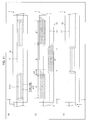
- FIG. 2 a method of forming the jacket-removed section I1.
- FIG. 2 is a sectional view illustrating a longitudinal section of the optical fiber 11 (i.e., a cross section including the central axis of the optical fiber 11).
- the jacket-removed section I1 is formed by chipping a part of the jacket 112 off by using a blade 2 having a linear blade edge 2a. More specifically, the jacket-removed section I1 is formed by carrying out the following steps S11 through S13 with respect to the optical fiber 11 that is being stretched between two fiber clamps while a predetermined tensile force is applied thereto.
- Step S11 First, the blade 2 is placed at a right end of the adjacent section 13 so that the blade edge 2a is brought into contact with the outer surface of the jacket 112. The blade 2 is then inserted obliquely into the jacket 112 so that the blade edge 2a is pressed to the outer surface of the inner cladding 111b at a right end of the jacket-removed section I1.
- (a) of Fig. 2 illustrates a longitudinal section of the optical fiber 11 which has been subjected to the process of the step S11.
- Step S12 Subsequently, the blade 2 is moved, while the blade edge 2a is being pressed to the outer surface of the inner cladding 111b, parallel to the central axis of the optical fiber 11 until the blade edge 2a reaches a left end of the jacket-removed section I1.
- (b) of Fig. 2 illustrates a longitudinal section of the optical fiber 11 which has been subjected to the process of the step S12.
- Step S13 Subsequently, the blade 2 is placed at a left end of the adjacent section 12 so that the blade edge 2a is brought into contact with the outer surface of the jacket 112. The blade 2 is then inserted obliquely into the jacket 112 so that the blade edge 2a is pressed to the outer surface of the inner cladding 111b at a left end of the jacket-removed section I1.
- (c) of Fig. 2 illustrates a longitudinal section of the optical fiber 11 which has been subjected to the process of the step S13.
- the blade edge 2a to the outer surface of the inner cladding 111b By pressing, in the step S12, the blade edge 2a to the outer surface of the inner cladding 111b with a sufficiently high pressure, it is possible to cause the depth d, by which the jacket 112 is removed in the jacket-removed section I1, to be greater than the thickness t' of the jacket 112 as illustrated in (b) of Fig. 1 . In other words, it is possible to expose, in the cross section of the jacket-removed section I1, a part of the outer surface of the inner cladding 111b within the range of ⁇ [rad] from the y-axis positive direction.
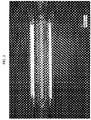
- Fig. 3 is a photomicrograph of the optical fiber 11 in which the jacket-removed section I1 is provided by the above-described method.
- a region in which the outer surface of the inner cladding 111b is exposed is surrounded by a white dotted line. According to Fig. 3 , it is shown in the cross section of the jacket-removed section I1 that a part of the outer surface of the inner cladding 111b is exposed within the range of ⁇ [rad] from the y-axis positive direction without being covered with the jacket 112.
- the optical device 1 can be produced by carrying out (i) the step S1 of forming the jacket-removed section I1 on the optical fiber 11 and (ii) the step S2 of embedding the jacket-removed section I1 of the optical fiber 11 in the resin member 12 having a refractive index higher than that of the inner cladding 111b of the optical fiber 11.
- the optical device 1 in accordance with the present embodiment can be produced by applying, to the step S1, the above-described method of forming the jacket-removed section I1.
- Fig. 4 is a sectional view (in which hatching is omitted) illustrating a cross section of the optical device 1 in the jacket-removed section I1 (i.e., the cross section orthogonal to the central axis of the optical fiber 11).
- the optical device 1 employs a configuration in which the jacket-removed section I1 embedded in the resin member 12 is a section in which a part of the jacket 112 is removed so that only a part of the outer surface of the inner cladding 111b (i.e., a part of the outer surface of the inner cladding 111b located in a direction that makes an angle of not more than ⁇ [rad] with the y-axis positive direction) is exposed in the cross section.
- the jacket-removed section I1 embedded in the resin member 12 is a section in which a part of the jacket 112 is removed so that only a part of the outer surface of the inner cladding 111b (i.e., a part of the outer surface of the inner cladding 111b located in a direction that makes an angle of not more than ⁇ [rad] with the y-axis positive direction) is exposed in the cross section.
- the optical device 1 employs a configuration in which the cut surface 112c1 of the jacket 112 in the jacket-removed section I1 is a flat surface having a normal vector v1 parallel to the radial direction of the optical fiber 11 (i.e., a y-axis positive direction) (see Fig. 4 ).
- This prevents the cladding light, having leaked from the outer surface of the inner cladding 111b into the resin member 12, from entering the jacket 112 through the cut surface 112c1.
- Fig. 5 is a graph showing a relationship between an amount of cladding light and an increased amount of a resin temperature (i.e., a difference between (i) a temperature of a resin member measured in the absence of cladding light and (ii) a maximum temperature of the resin member measured in the presence of cladding light), each of which is obtained in a case where a conventional optical device is used in which an entire outer surface of an inner cladding is exposed in a jacket-removed section.
- a resin temperature i.e., a difference between (i) a temperature of a resin member measured in the absence of cladding light and (ii) a maximum temperature of the resin member measured in the presence of cladding light
- Fig. 6 is a graph showing a relationship between an amount of cladding light and an increased amount of a resin temperature, each of which is obtained in a case where the jacket-removed section I1 of the optical device 1 in accordance with the present embodiment has a length L of 1 mm.
- Fig. 7 is a graph showing a relationship between an amount of cladding light and an increased amount of resin temperature, each of which is obtained in a case where the jacket-removed section I1 of the optical device 1 in accordance with the present embodiment has a length L of 2 mm.
- a graph indicating the increased amount of the resin temperature is at an inclination of 1.51°C/W (see Fig. 5 ).
- a graph indicating the increased amount of the resin temperature is at an inclination of 0.20°C/W in a case where the jacket-removed section I1 has a length L of 1 mm (see Fig. 6 )
- the graph indicating the increased amount of the resin temperature is at an inclination of 0.29°C/W in a case where the jacket-removed section I1 has a length L of 2 mm (see Fig. 7 ).
- the optical device 1 in accordance with the present embodiment makes it possible to reduce the increased amount of the resin temperature to not more than one-fifth of that of the conventional optical device.
- FIG. 8 A preferable length L of the jacket-removed section I1 will be discussed below with reference to Fig. 8 .
- FIG. 8 Each of (a) and (b) of Fig. 8 is a sectional view (in which hatching is omitted) illustrating a longitudinal section of the optical device 1 (i.e., a cross section including the central axis of the optical fiber 11), and (c) of Fig. 8 is a graph showing a temperature distribution in the resin member 12.
- the temperature of the resin member 12 reaches its peak at a point P at which cladding light, which has leaked from the outer surface of the inner cladding 111b into the resin member 12 at an entrance end of the jacket-removed section I1, reaches a surface of the resin member 12.
- a propagation angle ⁇ 1 of the cladding light, which has leaked from the outer surface of the inner cladding 111b into the resin member 12, is calculated by the following Equation (2). From this, a distance L0 from the entrance end of the jacket-removed section I1 to the point P, which distance L0 is measured along the central axis (i.e., a z axis in Fig. 8 ) of the optical fiber 11, is calculated by the following Equation (3).
- ⁇ 1 cos ⁇ 1 n 0 / n 1 cos ⁇ 0
- n0 is the refractive index of the inner cladding 111b
- n1 is the refractive index of the resin member 12.
- the temperature distribution in the resin member 12 becomes as indicated by a solid curve in (c) of Fig. 8 .
- the temperature of the resin member 12 at the point P i.e., a maximum temperature Tmax(L) of the resin member 12 varies in accordance with the length L of the jacket-removed section I1. More specifically, the maximum temperature Tmax(L) of the resin member 12 (i) drops as the length L of the jacket-removed section I1 is decreased and (ii) rises as the length of the jacket-removed section I1 is increased.
- the length L of the jacket-removed section I1 is preferably shorter than L0, which is defined by the above Equation (3). This is because, with such an arrangement, the maximum temperature Tmax(L) of the resin member 12 can be set to be lower than the maximum temperature Tmax, which is of the resin member 12 obtained when L ⁇ L0.
- Fig. 9 is a sectional view (in which hatching is omitted) illustrating the longitudinal section of the optical device 1 (i.e., the cross section including the central axis of the optical fiber 11).
- the propagation angle ⁇ 1 of the cladding light is calculated by the above Equation (2).
- an inclination of the cut surface 112c3 of the jacket 112 in the adjacent section 13 is preferably determined such that an angle ⁇ between a normal vector v3 of the cut surface 112c3 and the radial direction of the optical fiber 11 (i.e., the y-axis positive direction illustrated in Fig. 9 ) satisfies the following Equation (4).
- ⁇ ⁇ ⁇ 1 cos ⁇ 1 n 0 / n 1 cos ⁇ 0
- the cladding light which has leaked from the outer surface of the inner cladding 111b into the resin member 12, does not enter the jacket 112 through the cut surface 112c3. This makes it possible to prevent the jacket 112 from generating heat due to the cladding light which has leaked from the outer surface of the inner cladding 111b into the resin member 12.
- an inclination of the cut surface 112c2 of the jacket 112 in the adjacent section 12 on the entrance side is preferably determined as with the inclination of the cut surface 112c3 of the jacket 112 in the adjacent section 13 on the exit side. This makes it possible to prevent the jacket 112 from generating heat due to returning cladding light which has leaked from the outer surface of the inner cladding 111b into the resin member 12.
- Variation 1 of the optical device 1 will be discussed below with reference to Fig. 10 .
- (a) of Fig. 10 is a top view of an optical device 1 in accordance with Variation 1
- (b) of Fig. 10 is a lateral view of the optical device 1 in accordance with Variation 1
- (c) of Fig. 10 is a bottom view of the optical device 1 in accordance with Variation 1.
- the optical device 1 in accordance with Variation 1 is obtained by adding a second jacket-removed section I1' to the optical device 1 illustrated in Fig. 1 .
- the second jacket-removed section I1' is identical in structure to a first jacket-removed section I1.
- the outer surface of the inner cladding 111b is exposed in the y-axis positive direction in both of the first jacket-removed section I1 and the second jacket-removed section I1'.
- a gap G between the jacket-removed sections I1 and I1', in which the outer surface of the inner cladding 111b is exposed in the same direction, is preferably longer than L0 described above.
- the gap G between the jacket-removed sections I1 and I1' is equal to or shorter than L0, in the resin member 12, a region A1 which cladding light having leaked from the outer surface of the inner cladding 111b through the jacket-removed section I1 can reach overlaps with a region A2 which cladding light having leaked from the outer surface of the inner cladding 111b through the jacket-removed section I1' can reach.
- This may increase a maximum temperature of the resin member 12 in the region A1, as compared with the case where the jacket-removed section I1' is not provided.
- Such a problem can be eliminated by setting the gap G between the jacket-removed sections I1 and I1' to be longer than L0.
- FIG. 11 is a top view of an optical device 1 in accordance with Variation 2
- (b) of Fig. 11 is a lateral view of the optical device 1 in accordance with Variation 2
- (c) of Fig. 11 is a bottom view of the optical device 1 in accordance with Variation 2.
- the optical device 1 in accordance with Variation 2 is obtained by adding a second jacket-removed section I1' and a third jacket-removed section I1" to the optical device 1 illustrated in Fig. 1 .
- Each of the second jacket-removed section I1' and the third jacket-removed section I1" is identical in structure to a first jacket-removed section I1.
- the outer surface of the inner cladding 111b is exposed in the y-axis positive direction in both of the first jacket-removed section I1 and the third jacket-removed section I1".
- a gap G between the jacket-removed sections I1 and I1", in which the outer surface of the inner cladding 111b is exposed in the same direction, is preferably longer than L0 described above.
- the gap G between the jacket-removed sections I1 and I1" is equal to or shorter than L0, in the resin member 12, a region A1 which cladding light having leaked from the outer surface of the inner cladding 111b through the jacket-removed section I1 can reach overlaps with a region A3 which cladding light having leaked from the outer surface of the inner cladding 111b through the jacket-removed section I1" can reach.
- This may increase a maximum temperature of the resin member 12 in the region A1, as compared with the case where the jacket-removed section I1" is not provided.
- Such a problem is eliminated by setting the gap G between the jacket-removed sections I1 and I1" to be longer than L0.
- the first jacket-removed section I1 and the second jacket-removed section I1' are adjacent to each other. Moreover, the second jacket-removed section I1' and the third jacket-removed section I1" are adjacent to each other. It is preferable that the outer surface of the inner cladding 111b be exposed in different directions as in the jacket-removed sections I1 and I1'(I1' and I1") which are adjacent to each other.
- An optical device in accordance with an embodiment of the present invention includes: an optical fiber in which at least one jacket-removed section is provided; and a resin member in which the at least one jacket-removed section of the optical fiber is embedded, the resin member having a refractive index higher than a refractive index of a cladding of the optical fiber, the at least one jacket-removed section being a section in which a jacket covering an outer surface of the cladding has been partially removed so that only a part of the outer surface of the cladding is exposed in a cross section of the optical fiber.
- the above configuration makes it possible to reduce a maximum temperature of the resin member, as compared with a conventional optical device in which an entire outer surface of a cladding is exposed in a cross section in a jacket-removed section.
- the above configuration makes it possible to reduce the maximum temperature of the resin member, as compared with the case where the length L of the jacket-removed section is equal to or longer than L0.
- An optical device in accordance with an embodiment of the present invention is preferably configured such that the at least one jacket-removed section of the optical fiber includes a plurality of jacket-removed sections.
- the above configuration makes it possible to increase an amount of cladding light that leaks from the cladding into the resin member, as compared with the case where only one jacket-removed section is provided.
- the above configuration makes it possible to increase the amount of cladding light that leaks from the cladding into the resin member, as compared with the case where only one jacket-removed section is provided, without increasing the maximum temperature of the resin member.
- An optical device in accordance with an embodiment of the present invention is preferably configured such that the outer surface of the cladding is exposed in different directions in adjacent two of the plurality of jacket-removed sections.
- the above configuration makes it possible to increase the amount of cladding light that leaks from the cladding into the resin member, as compared with the case where only one jacket-removed section is provided, without increasing the maximum temperature of the resin member.
- An optical device in accordance with an embodiment of the present invention is preferably configured such that a cut surface of the jacket in the at least one jacket-removed section is a flat surface having a normal vector that is parallel to a radial direction of the optical fiber.
- the above configuration makes it possible to prevent light, which has leaked from the cladding into the resin member, from entering the jacket through the cut surface.
- An optical device in accordance with an embodiment of the present invention is preferably configured such that a cut surface of the jacket in an adjacent section adjacent to the at least one jacket-removed section is a flat surface having a normal vector that makes, with a radial direction of the optical fiber, an angle ⁇ that satisfies Equation (B) below: ⁇ ⁇ cos ⁇ 1 n 0 / n 1 cos ⁇ 0 where n0 is the refractive index of the cladding, ⁇ 0 is a critical propagation angle of light that propagates in the cladding, and n1 is the refractive index of the resin member.
- the above configuration makes it possible to prevent light, which has leaked from the cladding into the resin member, from entering the jacket through the cut surface.
- An optical device in accordance with an embodiment of the present invention can employ, for example, a double cladding fiber as the optical fiber.
- the at least one jacket-removed section can be provided by partially removing an outer cladding and an outer jacket so that only a part of an outer surface of an inner cladding is exposed in a cross section of the double cladding fiber.
- a method of producing an optical fiber in accordance with an embodiment of the present invention includes the steps of: forming a jacket-removed section in an optical fiber; and embedding the jacket-removed section of the optical fiber in a resin member having a refractive index higher than a refractive index of a cladding of the optical fiber, the jacket-removed section being a section in which a jacket covering an outer surface of the cladding has been partially removed so that only a part of the outer surface of the cladding is exposed in a cross section of the optical fiber.
- a method of producing an optical fiber in accordance with an embodiment of the present invention includes the steps of (i) forming a jacket-removed section in an optical fiber and (ii) embedding the jacket-removed section of the optical fiber in a resin member having a refractive index higher than that of cladding of the optical fiber, the step of forming the jacket-removed section being a step of partially removing a jacket covering an outer surface of the cladding in the jacket-removed section so that only a part of the outer surface of the cladding is exposed in a cross section in the jacket-removed section.
- the above configuration makes it possible to produce an optical device whose resin member is less likely to reach a high temperature, as compared with that of a conventional optical device.
- the present invention is applicable to a general optical fiber such as a double cladding fiber and a triple cladding fiber in which light can be confined to a cladding.
- the present invention is also applicable to a fiber laser, a fiber amplifier, and the like.
Landscapes
- Physics & Mathematics (AREA)
- General Physics & Mathematics (AREA)
- Optics & Photonics (AREA)
- Optical Couplings Of Light Guides (AREA)
- Optical Fibers, Optical Fiber Cores, And Optical Fiber Bundles (AREA)
- Lasers (AREA)
Abstract
Description
- The present invention relates to an optical device including (i) an optical fiber in which a jacket-removed section is provided and (ii) a resin member in which the jacket-removed section is embedded. The present invention also relates to a method of producing such an optical device.
- Optical fibers such as double cladding fibers and triple cladding fibers, in which light can be confined to a cladding, are in wide use. According to such an optical fiber, unnecessary light that propagates in a cladding (hereinafter referred to as "cladding light") may cause heating in a jacket which covers an outer surface of the cladding. Under the circumstances, in such an optical fiber, it is necessary to cause the cladding light to leak from the cladding through a jacket-removed section in which the jacket has been removed.
-
Patent Literature 1 discloses an optical device including (i) an optical fiber in which a jacket-removed section is provided (jacket is referred to as a "pre-coating" in Patent Literature 1) and (ii) a resin member in which the jacket-removed section is embedded. According to the optical device disclosed inPatent Literature 1, a refractive index of the resin member is set to be higher than that of a cladding so that cladding light will leak from the cladding into the resin member through the jacket-removed section. - [Patent Literature 1]
Japanese Patent Application Publication Tokukaihei No.1-316705 (1989) (Publication Date: December 21, 1989 - In a case where such a jacket-removed section, in which a jacket for covering an outer surface of a cladding has been removed, is embedded in a resin member having a refractive index higher than that of the cladding as with the optical device disclosed in
Patent Literature 1, cladding light will leak intensively at an entrance end of the jacket-removed section. This causes the resin member near the entrance end of the jacket-removed section to absorb the cladding light and accordingly reach a high temperature. - The present invention has been accomplished in view of the above problem, and an object of an aspect of the present invention is to provide an optical device (i) which includes (a) an optical fiber in which a jacket-removed section is provided and (b) a resin member in which the jacket-removed section is embedded and (ii) in which the resin member is less likely to reach a high temperature, as compared with that of a conventional optical device.
- In order to attain the above object, an optical device in accordance with an aspect of the present invention includes: an optical fiber in which at least one jacket-removed section is provided; and a resin member in which the at least one jacket-removed section of the optical fiber is embedded, the resin member having a refractive index higher than a refractive index of a cladding of the optical fiber, the at least one jacket-removed section being a section in which a jacket covering an outer surface of the cladding has been partially removed so that only a part of the outer surface of the cladding is exposed in a cross section of the optical fiber.
- In order to attain the above object, a method of producing an optical fiber in accordance with an aspect of the present invention includes the steps of: forming a jacket-removed section in an optical fiber; and embedding the jacket-removed section of the optical fiber in a resin member having a refractive index higher than a refractive index of a cladding of the optical fiber, the jacket-removed section being a section in which a jacket covering an outer surface of the cladding has been partially removed so that only a part of the outer surface of the cladding is exposed in a cross section of the optical fiber.
- The present invention makes it possible to provide an optical device in which a resin member is less likely to reach a high temperature, as compared with that of a conventional optical device.
-
-
Fig. 1 is a view for describing a configuration of an optical device in accordance with an embodiment of the present invention. (a) ofFig. 1 is a top view of the optical device, (b) ofFig. 1 is a lateral view of the optical device, (c) ofFig. 1 is an A-A' sectional view of the optical device, and (d) ofFig. 1 is a B-B' sectional view of the optical device. -
Fig. 2 is a view for describing a method of forming a jacket-removed section in the optical device illustrated inFig. 1 . Each of (a) through (c) ofFig. 2 is a (longitudinal) sectional view of an optical fiber of the optical device. -
Fig. 3 is a photomicrograph of the optical fiber in which the jacket-removed section is provided by the method illustrated inFig. 2 . -
Fig. 4 is a (cross) sectional view of the optical device illustrated inFig. 1 for describing an effect yielded by the optical device. -
Fig. 5 is a graph showing a relationship between an amount of cladding light and an increased amount of a resin temperature, each of which is obtained in a conventional optical device. -
Fig. 6 is a graph showing a relationship between an amount of cladding light and an increased amount of a resin temperature, each of which is obtained in a case where the jacket-removed section of the optical device illustrated inFig. 1 has a length of 1 mm. -
Fig. 7 is a graph showing a relationship between an amount of cladding light and an increased amount of a resin temperature, each of which is obtained in a case where the jacket-removed section of the optical device illustrated inFig. 1 has a length of 2 mm. -
Fig. 8 is a view for describing a preferable length of the jacket-removed section of the optical device illustrated inFig. 1 . Each of (a) and (b) ofFig. 8 is a (longitudinal) sectional view of the optical fiber, and (c) is a graph showing a temperature distribution in the resin member. -
Fig. 9 is a (longitudinal) sectional view of the optical device illustrated inFig. 1 for describing a preferable inclination of a cut surface of a jacket in the optical device. -
Fig. 10 is a view for describingVariation 1 of the optical device illustrated inFig. 1 . (a) ofFig. 10 is a top view of the optical device, (b) ofFig. 10 is a lateral view of the optical device, and (c) ofFig. 10 is a bottom view of the optical device. -
Fig. 11 is a view for describingVariation 2 of the optical device illustrated inFig. 1 . (a) ofFig. 11 is a top view of the optical device, (b) ofFig. 11 is a lateral view of the optical device, and (c) ofFig. 11 is a bottom view of the optical device. - The following description will discuss an embodiment of an optical device in accordance with the present invention with reference to the drawings.
- A configuration of an
optical device 1 in accordance with the present embodiment will be discussed below with reference toFig. 1 . (a) ofFig. 1 is a top view of theoptical device 1, (b) ofFig. 1 is a lateral view of theoptical device 1, (c) ofFig. 1 is an A-A' sectional view of theoptical device 1, and (d) ofFig. 1 is a B-B' sectional view (in which hatching is omitted) of theoptical device 1. - As illustrated in (a) through (d) of
Fig. 1 , theoptical device 1 includes (i) anoptical fiber 11 in which a jacket-removed section I1 is provided and (ii) aresin member 12 in which the jacket-removed section I1 of theoptical fiber 11 is embedded. - The
optical fiber 11, which is a double cladding fiber, includes (i) acore 111a having a columnar shape, (ii) aninner cladding 111b having a cylindrical shape and covering a side surface of thecore 111a, (iii) anouter cladding 112a having a cylindrical shape and covering an outer surface of theinner cladding 111b, and (iv) anouter jacket 112b having a cylindrical shape and covering an outer surface of theouter cladding 112a (see (c) ofFig. 1 ). - According to the
optical fiber 11, each of thecore 111a and theinner cladding 111b is made of glass. Thecore 111a and theinner cladding 111b will be hereinafter collectively referred to as abare fiber 111. According to theoptical fiber 11, each of theouter cladding 112a and theouter jacket 112b is made of resin. Theouter cladding 112a and theouter jacket 112b will be hereinafter collectively referred to as ajacket 112. - The jacket-removed section I1 of the
optical fiber 11 is a section in which thejacket 112, which covers the outer surface of theinner cladding 111b, has been partially removed so that a part of the outer surface of theinner cladding 111b is exposed in a cross section (i.e., a section orthogonal to a central axis of the optical fiber 11). - According to the present embodiment, a part of the
jacket 112 is removed in the jacket-removed section I1 andadjacent sections Fig. 1 ). A cut surface 112c1 of thejacket 112 in the jacket-removed section I1 is therefore a rectangular flat surface having a normal vector v1 which is parallel to a radial direction of the optical fiber 11 (i.e., a y-axis positive direction illustrated inFig. 1 ) (see (a) and (b) ofFig. 1 ). Cut surfaces 112c2 and 112c3 of thejacket 112 in the respectiveadjacent sections Fig. 1 ) (see (a) and (b) ofFig. 1 ). - According to the present embodiment, the
jacket 112 is removed in the jacket-removed section I1 by a depth d, which is greater than a thickness t' of the jacket 112 (i.e., a sum of thicknesses of theouter cladding 112a and theouter jacket 112b) (see (b) ofFig. 1 ). Therefore, in the cross section of the jacket-removed section I1, a part of the outer surface of theinner cladding 111b is exposed within a range of ±β[rad] from the y-axis positive direction without being covered with the jacket 112 (see (d) ofFig. 1 ). Note that β is calculated by the following Equation (1):
optical fiber 11. - The jacket-removed section I1 of the
optical fiber 11 is embedded in theresin member 12 having a refractive index higher than that of theinner cladding 111b of theoptical fiber 11. This allows cladding light, which has propagated in theinner cladding 111b of theoptical fiber 11, to leak from the outer surface of theinner cladding 111b into theresin member 12 in the jacket-removed section I1. The present embodiment employs, as theresin member 12, a rectangular-parallelepiped resin molded product whose one side surface (i.e., a side surface parallel to a z-x plane inFig. 1 ) faces the cut surface 112c1 of the jacket 112 (seeFig. 1 ). - The following description will discuss, with reference to
Fig. 2 , a method of forming the jacket-removed section I1. Each of (a) through (c) ofFig. 2 is a sectional view illustrating a longitudinal section of the optical fiber 11 (i.e., a cross section including the central axis of the optical fiber 11). - The jacket-removed section I1 is formed by chipping a part of the
jacket 112 off by using ablade 2 having alinear blade edge 2a. More specifically, the jacket-removed section I1 is formed by carrying out the following steps S11 through S13 with respect to theoptical fiber 11 that is being stretched between two fiber clamps while a predetermined tensile force is applied thereto. - Step S11: First, the
blade 2 is placed at a right end of theadjacent section 13 so that theblade edge 2a is brought into contact with the outer surface of thejacket 112. Theblade 2 is then inserted obliquely into thejacket 112 so that theblade edge 2a is pressed to the outer surface of theinner cladding 111b at a right end of the jacket-removed section I1. (a) ofFig. 2 illustrates a longitudinal section of theoptical fiber 11 which has been subjected to the process of the step S11. - Step S12: Subsequently, the
blade 2 is moved, while theblade edge 2a is being pressed to the outer surface of theinner cladding 111b, parallel to the central axis of theoptical fiber 11 until theblade edge 2a reaches a left end of the jacket-removed section I1. (b) ofFig. 2 illustrates a longitudinal section of theoptical fiber 11 which has been subjected to the process of the step S12. - Step S13: Subsequently, the
blade 2 is placed at a left end of theadjacent section 12 so that theblade edge 2a is brought into contact with the outer surface of thejacket 112. Theblade 2 is then inserted obliquely into thejacket 112 so that theblade edge 2a is pressed to the outer surface of theinner cladding 111b at a left end of the jacket-removed section I1. (c) ofFig. 2 illustrates a longitudinal section of theoptical fiber 11 which has been subjected to the process of the step S13. - By pressing, in the step S12, the
blade edge 2a to the outer surface of theinner cladding 111b with a sufficiently high pressure, it is possible to cause the depth d, by which thejacket 112 is removed in the jacket-removed section I1, to be greater than the thickness t' of thejacket 112 as illustrated in (b) ofFig. 1 . In other words, it is possible to expose, in the cross section of the jacket-removed section I1, a part of the outer surface of theinner cladding 111b within the range of ±β[rad] from the y-axis positive direction. - The following description will confirm, with reference to
Fig. 3 , that the jacket-removed section I1 illustrated inFig. 1 can be formable by the above-described method.Fig. 3 is a photomicrograph of theoptical fiber 11 in which the jacket-removed section I1 is provided by the above-described method. - In
Fig. 3 , a region in which the outer surface of theinner cladding 111b is exposed is surrounded by a white dotted line. According toFig. 3 , it is shown in the cross section of the jacket-removed section I1 that a part of the outer surface of theinner cladding 111b is exposed within the range of ±β[rad] from the y-axis positive direction without being covered with thejacket 112. - The
optical device 1 can be produced by carrying out (i) the step S1 of forming the jacket-removed section I1 on theoptical fiber 11 and (ii) the step S2 of embedding the jacket-removed section I1 of theoptical fiber 11 in theresin member 12 having a refractive index higher than that of theinner cladding 111b of theoptical fiber 11. Theoptical device 1 in accordance with the present embodiment can be produced by applying, to the step S1, the above-described method of forming the jacket-removed section I1. - An effect yielded by the
optical device 1 in accordance with the present embodiment will be discussed below with reference toFigs. 4 through 7 . -
Fig. 4 is a sectional view (in which hatching is omitted) illustrating a cross section of theoptical device 1 in the jacket-removed section I1 (i.e., the cross section orthogonal to the central axis of the optical fiber 11). - As illustrated in
Fig. 4 , theoptical device 1 employs a configuration in which the jacket-removed section I1 embedded in theresin member 12 is a section in which a part of thejacket 112 is removed so that only a part of the outer surface of theinner cladding 111b (i.e., a part of the outer surface of theinner cladding 111b located in a direction that makes an angle of not more than β[rad] with the y-axis positive direction) is exposed in the cross section. It follows that a region A which is of theresin member 12 and which cladding light having leaked from the outer surface of theinner cladding 111b reaches, i.e., the region A which generates heat in theresin member 12, is restricted to a part of the resin member 12 (i.e., a part of theresin member 12 located in the direction that makes an angle of not more than β[rad] with the y-axis positive direction) (seeFig. 4 ). - Heat generated inside the region A of the
resin member 12 diffuses to outside of the region A. This allows a maximum temperature of theresin member 12, i.e., a temperature of theresin member 12 in the region A, to be lower than that of a conventional optical device in which an entire outer surface of an inner cladding is exposed in a jacket-removed section. - Furthermore, the
optical device 1 employs a configuration in which the cut surface 112c1 of thejacket 112 in the jacket-removed section I1 is a flat surface having a normal vector v1 parallel to the radial direction of the optical fiber 11 (i.e., a y-axis positive direction) (seeFig. 4 ). This prevents the cladding light, having leaked from the outer surface of theinner cladding 111b into theresin member 12, from entering thejacket 112 through the cut surface 112c1. This ultimately prevents thejacket 112 from generating heat due to the cladding light having leaked from the outer surface of theinner cladding 111b into theresin member 12. - The above-described effect yielded by the
optical device 1 in accordance with the present embodiment can be confirmed with reference toFigs. 5 through 7 . -
Fig. 5 is a graph showing a relationship between an amount of cladding light and an increased amount of a resin temperature (i.e., a difference between (i) a temperature of a resin member measured in the absence of cladding light and (ii) a maximum temperature of the resin member measured in the presence of cladding light), each of which is obtained in a case where a conventional optical device is used in which an entire outer surface of an inner cladding is exposed in a jacket-removed section.Fig. 6 is a graph showing a relationship between an amount of cladding light and an increased amount of a resin temperature, each of which is obtained in a case where the jacket-removed section I1 of theoptical device 1 in accordance with the present embodiment has a length L of 1 mm.Fig. 7 is a graph showing a relationship between an amount of cladding light and an increased amount of resin temperature, each of which is obtained in a case where the jacket-removed section I1 of theoptical device 1 in accordance with the present embodiment has a length L of 2 mm. - Note that each of graphs shown in
Figs. 5 through 7 was obtained under conditions where (i) a numerical aperture NAO of the inner cladding (111b) was 0.3, (ii) a refractive index n0 of the inner cladding (111b) was 1.45, (iii) a thickness t of the resin member (12) was 0.8 mm, and (iv) a refractive index n1 of the resin member (12) was 1.54. - According to the conventional optical device, a graph indicating the increased amount of the resin temperature is at an inclination of 1.51°C/W (see
Fig. 5 ). In contrast, according to theoptical device 1 in accordance with the present embodiment, a graph indicating the increased amount of the resin temperature is at an inclination of 0.20°C/W in a case where the jacket-removed section I1 has a length L of 1 mm (seeFig. 6 ), and the graph indicating the increased amount of the resin temperature is at an inclination of 0.29°C/W in a case where the jacket-removed section I1 has a length L of 2 mm (seeFig. 7 ). As such, theoptical device 1 in accordance with the present embodiment makes it possible to reduce the increased amount of the resin temperature to not more than one-fifth of that of the conventional optical device. - A preferable length L of the jacket-removed section I1 will be discussed below with reference to
Fig. 8 . Each of (a) and (b) ofFig. 8 is a sectional view (in which hatching is omitted) illustrating a longitudinal section of the optical device 1 (i.e., a cross section including the central axis of the optical fiber 11), and (c) ofFig. 8 is a graph showing a temperature distribution in theresin member 12. - The temperature of the
resin member 12 reaches its peak at a point P at which cladding light, which has leaked from the outer surface of theinner cladding 111b into theresin member 12 at an entrance end of the jacket-removed section I1, reaches a surface of theresin member 12. A propagation angle θ1 of the cladding light, which has leaked from the outer surface of theinner cladding 111b into theresin member 12, is calculated by the following Equation (2). From this, a distance L0 from the entrance end of the jacket-removed section I1 to the point P, which distance L0 is measured along the central axis (i.e., a z axis inFig. 8 ) of theoptical fiber 11, is calculated by the following Equation (3).
inner cladding 111b, θ0 is a critical propagation angle of the cladding light (here, θ0 = sin-1(NA0/n0) holds true where NA0 is the numerical aperture of theinner cladding 111b), and n1 is the refractive index of theresin member 12.
resin member 12. - In a case where the length L of the jacket-removed section I1 is equal to or longer than L0 as illustrated in (a) of
Fig. 8 , the temperature distribution in theresin member 12 becomes as indicated by a dotted curve in (c) ofFig. 8 . This means that, in a case where the length L of the jacket-removed section I1 is equal to or longer than L0, a temperature of theresin member 12 at the point P, i.e., a maximum temperature Tmax of theresin member 12, is constant regardless of the length L of the jacket-removedsection 11. - In contrast, in a case where the length L of the jacket-removed section I1 is shorter than L0 as illustrated in (b) of
Fig. 8 , the temperature distribution in theresin member 12 becomes as indicated by a solid curve in (c) ofFig. 8 . This means that, in a case where the length L of the jacket-removed section I1 is shorter than L0, the temperature of theresin member 12 at the point P, i.e., a maximum temperature Tmax(L) of theresin member 12 varies in accordance with the length L of the jacket-removed section I1. More specifically, the maximum temperature Tmax(L) of the resin member 12 (i) drops as the length L of the jacket-removed section I1 is decreased and (ii) rises as the length of the jacket-removed section I1 is increased. - From the above description, the length L of the jacket-removed section I1 is preferably shorter than L0, which is defined by the above Equation (3). This is because, with such an arrangement, the maximum temperature Tmax(L) of the
resin member 12 can be set to be lower than the maximum temperature Tmax, which is of theresin member 12 obtained when L ≥ L0. - A preferable inclination of a cut surface 112c3 of the
jacket 112 in theadjacent section 13 on an exit side will be discussed below with reference toFig. 9. Fig. 9 is a sectional view (in which hatching is omitted) illustrating the longitudinal section of the optical device 1 (i.e., the cross section including the central axis of the optical fiber 11). - As described above, assuming that the refractive index of the
inner cladding 111b is represented by n0, the critical propagation angle of the cladding light is represented by θ0, and the refractive index of theresin member 12 is represented by n1, the propagation angle θ1 of the cladding light, which has leaked from the outer surface of theinner cladding 111b into theresin member 12, is calculated by the above Equation (2). - From this, an inclination of the cut surface 112c3 of the
jacket 112 in theadjacent section 13 is preferably determined such that an angle α between a normal vector v3 of the cut surface 112c3 and the radial direction of the optical fiber 11 (i.e., the y-axis positive direction illustrated inFig. 9 ) satisfies the following Equation (4).
- In a case where the angle α between the normal vector v3 of the cut surface 112c3 and the radial direction of the
optical fiber 11 satisfies the above Equation (4), the cladding light, which has leaked from the outer surface of theinner cladding 111b into theresin member 12, does not enter thejacket 112 through the cut surface 112c3. This makes it possible to prevent thejacket 112 from generating heat due to the cladding light which has leaked from the outer surface of theinner cladding 111b into theresin member 12. - Note that an inclination of the cut surface 112c2 of the
jacket 112 in theadjacent section 12 on the entrance side is preferably determined as with the inclination of the cut surface 112c3 of thejacket 112 in theadjacent section 13 on the exit side. This makes it possible to prevent thejacket 112 from generating heat due to returning cladding light which has leaked from the outer surface of theinner cladding 111b into theresin member 12. -
Variation 1 of theoptical device 1 will be discussed below with reference toFig. 10 . (a) ofFig. 10 is a top view of anoptical device 1 in accordance withVariation 1, (b) ofFig. 10 is a lateral view of theoptical device 1 in accordance withVariation 1, and (c) ofFig. 10 is a bottom view of theoptical device 1 in accordance withVariation 1. - The
optical device 1 in accordance withVariation 1 is obtained by adding a second jacket-removed section I1' to theoptical device 1 illustrated inFig. 1 . The second jacket-removed section I1' is identical in structure to a first jacket-removed section I1. - By adding the second jacket-removed section I1', it is possible to increase an amount of cladding light that leaks from an outer surface of an
inner cladding 111b into aresin member 12, as compared with theoptical device 1 illustrated inFig. 1 . - The outer surface of the
inner cladding 111b is exposed in the y-axis positive direction in both of the first jacket-removed section I1 and the second jacket-removed section I1'. A gap G between the jacket-removed sections I1 and I1', in which the outer surface of theinner cladding 111b is exposed in the same direction, is preferably longer than L0 described above. - If the gap G between the jacket-removed sections I1 and I1' is equal to or shorter than L0, in the
resin member 12, a region A1 which cladding light having leaked from the outer surface of theinner cladding 111b through the jacket-removed section I1 can reach overlaps with a region A2 which cladding light having leaked from the outer surface of theinner cladding 111b through the jacket-removed section I1' can reach. This may increase a maximum temperature of theresin member 12 in the region A1, as compared with the case where the jacket-removed section I1' is not provided. Such a problem can be eliminated by setting the gap G between the jacket-removed sections I1 and I1' to be longer than L0. -
Variation 2 of theoptical device 1 will be discussed below with reference toFig. 1 1 . (a) ofFig. 11 is a top view of anoptical device 1 in accordance withVariation 2, (b) ofFig. 11 is a lateral view of theoptical device 1 in accordance withVariation 2, and (c) ofFig. 11 is a bottom view of theoptical device 1 in accordance withVariation 2. - The
optical device 1 in accordance withVariation 2 is obtained by adding a second jacket-removed section I1' and a third jacket-removed section I1" to theoptical device 1 illustrated inFig. 1 . Each of the second jacket-removed section I1' and the third jacket-removed section I1" is identical in structure to a first jacket-removed section I1. - By adding the second jacket-removed section I1' and the third jacket-removed section I1", it is possible to increase an amount of cladding light that leaks from an outer surface of an
inner cladding 111b into aresin member 12, as compared with theoptical device 1 illustrated inFig. 1 . - The outer surface of the
inner cladding 111b is exposed in the y-axis positive direction in both of the first jacket-removed section I1 and the third jacket-removed section I1". A gap G between the jacket-removed sections I1 and I1", in which the outer surface of theinner cladding 111b is exposed in the same direction, is preferably longer than L0 described above. - If the gap G between the jacket-removed sections I1 and I1" is equal to or shorter than L0, in the
resin member 12, a region A1 which cladding light having leaked from the outer surface of theinner cladding 111b through the jacket-removed section I1 can reach overlaps with a region A3 which cladding light having leaked from the outer surface of theinner cladding 111b through the jacket-removed section I1" can reach. This may increase a maximum temperature of theresin member 12 in the region A1, as compared with the case where the jacket-removed section I1" is not provided. Such a problem is eliminated by setting the gap G between the jacket-removed sections I1 and I1" to be longer than L0. - The first jacket-removed section I1 and the second jacket-removed section I1' are adjacent to each other. Moreover, the second jacket-removed section I1' and the third jacket-removed section I1" are adjacent to each other. It is preferable that the outer surface of the
inner cladding 111b be exposed in different directions as in the jacket-removed sections I1 and I1'(I1' and I1") which are adjacent to each other. - If the outer surface of the
inner cladding 111b is exposed in the same direction in the adjacent jacket-removed sections I1 and I1'(I1' and I1"), a region A1 (A2) which cladding light having leaked from the outer surface of theinner cladding 111b through the jacket-removed section I1 (I1') can reach overlaps with a region A2 (A3), which cladding light having leaked from the outer surface of theinner cladding 111b through the jacket-removed section I1'(I1") can reach. This may increase the maximum temperature of theresin member 12 in the region A1 (A2), as compared with the case where the jacket-removed section I1' (I1") is not provided. Such a problem eliminated by setting the outer surface of theinner cladding 111b to be exposed in different directions in the adjacent jacket-removed sections I1 and I1' (I1' and I1"). - An optical device in accordance with an embodiment of the present invention includes: an optical fiber in which at least one jacket-removed section is provided; and a resin member in which the at least one jacket-removed section of the optical fiber is embedded, the resin member having a refractive index higher than a refractive index of a cladding of the optical fiber, the at least one jacket-removed section being a section in which a jacket covering an outer surface of the cladding has been partially removed so that only a part of the outer surface of the cladding is exposed in a cross section of the optical fiber.
- According to the above configuration, only a part of the outer surface of the cladding is exposed in the cross section of the jacket-removed section, so that it is possible to restrict a region which cladding light having leaked from the cladding reaches in the resin member, i.e., a region which generates heat in the resin member, to a part of a region in the resin member. The heat generated in the region of the resin member diffuses to outside of the region. As such, the above configuration makes it possible to reduce a maximum temperature of the resin member, as compared with a conventional optical device in which an entire outer surface of a cladding is exposed in a cross section in a jacket-removed section.
- An optical device in accordance with an embodiment of the present invention is preferably configured such that a length L of the at least one jacket-removed section is shorter than L0 which is defined by Equation (A) below:

- The above configuration makes it possible to reduce the maximum temperature of the resin member, as compared with the case where the length L of the jacket-removed section is equal to or longer than L0.
- An optical device in accordance with an embodiment of the present invention is preferably configured such that the at least one jacket-removed section of the optical fiber includes a plurality of jacket-removed sections.
- The above configuration makes it possible to increase an amount of cladding light that leaks from the cladding into the resin member, as compared with the case where only one jacket-removed section is provided.
- An optical device in accordance with an embodiment of the present invention is preferably configured such that the plurality of jacket-removed sections include two jacket-removed sections in which the outer surface of the cladding is exposed in identical directions; and a gap G between the two jacket-removed sections is longer than L0 which is defined by Equation (A) below:

- The above configuration makes it possible to increase the amount of cladding light that leaks from the cladding into the resin member, as compared with the case where only one jacket-removed section is provided, without increasing the maximum temperature of the resin member.
- An optical device in accordance with an embodiment of the present invention is preferably configured such that the outer surface of the cladding is exposed in different directions in adjacent two of the plurality of jacket-removed sections.
- The above configuration makes it possible to increase the amount of cladding light that leaks from the cladding into the resin member, as compared with the case where only one jacket-removed section is provided, without increasing the maximum temperature of the resin member.
- An optical device in accordance with an embodiment of the present invention is preferably configured such that a cut surface of the jacket in the at least one jacket-removed section is a flat surface having a normal vector that is parallel to a radial direction of the optical fiber.
- The above configuration makes it possible to prevent light, which has leaked from the cladding into the resin member, from entering the jacket through the cut surface.
- An optical device in accordance with an embodiment of the present invention is preferably configured such that a cut surface of the jacket in an adjacent section adjacent to the at least one jacket-removed section is a flat surface having a normal vector that makes, with a radial direction of the optical fiber, an angle α that satisfies Equation (B) below:

- The above configuration makes it possible to prevent light, which has leaked from the cladding into the resin member, from entering the jacket through the cut surface.
- An optical device in accordance with an embodiment of the present invention can employ, for example, a double cladding fiber as the optical fiber. In this case, the at least one jacket-removed section can be provided by partially removing an outer cladding and an outer jacket so that only a part of an outer surface of an inner cladding is exposed in a cross section of the double cladding fiber.
- A method of producing an optical fiber in accordance with an embodiment of the present invention includes the steps of: forming a jacket-removed section in an optical fiber; and embedding the jacket-removed section of the optical fiber in a resin member having a refractive index higher than a refractive index of a cladding of the optical fiber, the jacket-removed section being a section in which a jacket covering an outer surface of the cladding has been partially removed so that only a part of the outer surface of the cladding is exposed in a cross section of the optical fiber. In other words, a method of producing an optical fiber in accordance with an embodiment of the present invention includes the steps of (i) forming a jacket-removed section in an optical fiber and (ii) embedding the jacket-removed section of the optical fiber in a resin member having a refractive index higher than that of cladding of the optical fiber, the step of forming the jacket-removed section being a step of partially removing a jacket covering an outer surface of the cladding in the jacket-removed section so that only a part of the outer surface of the cladding is exposed in a cross section in the jacket-removed section.
- The above configuration makes it possible to produce an optical device whose resin member is less likely to reach a high temperature, as compared with that of a conventional optical device.
- The present invention is not limited to the embodiments described herein, but can be altered by a skilled person in the art within the scope of the claims. That is, an embodiment derived from a proper combination of technical means appropriately modified within the scope of the claims is also encompassed in the technical scope of the present invention.
- The present invention is applicable to a general optical fiber such as a double cladding fiber and a triple cladding fiber in which light can be confined to a cladding. The present invention is also applicable to a fiber laser, a fiber amplifier, and the like.
-
- 1 Optical device
- 11 Optical fiber
- 111 Bare fiber
- 111a Core
- 111b Inner cladding (cladding)
- 112 Jacket
- 112a Outer cladding
- 112b Outer jacket
- 112c1 Cut surface of jacket in jacket-removed section
- 112c2 and 112c3 Cut surface of jacket in adjacent section
- I1, I1', and I1" Jacket-removed section
- 12 and 13 Adjacent section
- 12 Resin member
- L Length of jacket-removed section
- n0 Refractive index of inner cladding
- θ0 Critical propagation angle of cladding light (light that propagates in cladding)
- n1 Refractive index of resin member
- t Thickness of resin member
- v1 Normal vector of cut surface of jacket in jacket-removed section
- v2 and v3 Normal vector of cut surface of jacket in adjacent section
Claims (9)
- An optical device, comprising:an optical fiber in which at least one jacket-removed section is provided; anda resin member in which the at least one jacket-removed section of the optical fiber is embedded, the resin member having a refractive index higher than a refractive index of a cladding of the optical fiber,the at least one jacket-removed section being a section in which a jacket covering an outer surface of the cladding has been partially removed so that only a part of the outer surface of the cladding is exposed in a cross section of the optical fiber.
- The optical device as set forth in claim 1, wherein:a length L of the at least one jacket-removed section is shorter than L0 which is defined by Equation (A) below:

- The optical device as set forth in claim 1 or 2, wherein:
the at least one jacket-removed section of the optical fiber includes a plurality of jacket-removed sections. - The optical device as set forth in claim 3, wherein:the plurality of jacket-removed sections include two jacket-removed sections in which the outer surface of the cladding is exposed in identical directions; anda gap G between the two jacket-removed sections is longer than L0 which is defined by Equation (A) below:where n0 is the refractive index of the cladding, θ0 is a critical propagation angle of light that propagates in the cladding, n1 is the refractive index of the resin member, and t is a thickness of the resin member.

- The optical device as set forth in claim 3 or 4, wherein:the outer surface of the cladding is exposed in different directions in adjacent two of the plurality of jacket-removed sections.
- The optical device as set forth in any one of claims 1 through 5, wherein:
a cut surface of the jacket in the at least one jacket-removed section is a flat surface having a normal vector that is parallel to a radial direction of the optical fiber. - The optical device as set forth in any one of claims 1 through 6, wherein:a cut surface of the jacket in an adjacent section adjacent to the at least one jacket-removed section is a flat surface having a normal vector that makes, with a radial direction of the optical fiber, an angle α that satisfies Equation (B) below:

- The optical device as set forth in any one of claims 1 through 7, wherein:the optical fiber includes:a core which is made of glass;an inner cladding which is made of glass and covers a side surface of the core;an outer cladding which is made of resin and covers an outer surface of the inner cladding; andan outer jacket which is made of resin and covers an outer surface of the outer cladding;the cladding is the inner cladding; andthe jacket includes the outer cladding and the outer jacket.
- A method of producing an optical device, comprising the steps of:
forming a jacket-removed section in an optical fiber; and
embedding the jacket-removed section of the optical fiber in a resin member having a refractive index higher than a refractive index of a cladding of the optical fiber,
the jacket-removed section being a section in which a jacket covering an outer surface of the cladding has been partially removed so that only a part of the outer surface of the cladding is exposed in a cross section of the optical fiber.
Applications Claiming Priority (2)
| Application Number | Priority Date | Filing Date | Title |
|---|---|---|---|
| JP2014155419A JP5850992B1 (en) | 2014-07-30 | 2014-07-30 | Optical device and method for manufacturing optical device |
| PCT/JP2015/056096 WO2016017197A1 (en) | 2014-07-30 | 2015-03-02 | Optical device and optical device manufacturing method |
Publications (2)
| Publication Number | Publication Date |
|---|---|
| EP3176618A1 true EP3176618A1 (en) | 2017-06-07 |
| EP3176618A4 EP3176618A4 (en) | 2017-07-19 |
Family
ID=55217102
Family Applications (1)
| Application Number | Title | Priority Date | Filing Date |
|---|---|---|---|
| EP15828316.8A Withdrawn EP3176618A4 (en) | 2014-07-30 | 2015-03-02 | Optical device and optical device manufacturing method |
Country Status (5)
| Country | Link |
|---|---|
| US (1) | US9977181B2 (en) |
| EP (1) | EP3176618A4 (en) |
| JP (1) | JP5850992B1 (en) |
| CN (1) | CN106662718A (en) |
| WO (1) | WO2016017197A1 (en) |
Families Citing this family (9)
| Publication number | Priority date | Publication date | Assignee | Title |
|---|---|---|---|---|
| JP2017181822A (en) * | 2016-03-30 | 2017-10-05 | 株式会社フジクラ | Optical component and laser device |
| JP6807662B2 (en) * | 2016-06-14 | 2021-01-06 | 浜松ホトニクス株式会社 | Method for manufacturing laser oscillator and excitation light detection structure |
| JP2018098307A (en) * | 2016-12-09 | 2018-06-21 | 株式会社フジクラ | Fiber laser device |
| JP2019070760A (en) * | 2017-10-10 | 2019-05-09 | 株式会社フジクラ | Optical device and laser device |
| JP2020034664A (en) * | 2018-08-29 | 2020-03-05 | 株式会社フジクラ | Cladding mode light removing structure, laser device, and method of manufacturing cladding mode light removing structure |
| CN112888977B (en) | 2018-09-10 | 2023-12-19 | 恩耐公司 | Optical fiber splicing encapsulated by cladding optical stripper |
| WO2020061505A1 (en) * | 2018-09-21 | 2020-03-26 | Nlight, Inc. | Optical fiber cladding light stripper |
| JP2020085998A (en) * | 2018-11-19 | 2020-06-04 | 株式会社フジクラ | Cladding mode light removal structure and laser device |
| TWI789166B (en) * | 2021-12-14 | 2023-01-01 | 搏盟科技股份有限公司 | Gradient optical fiber cladding optical stripper and manufacturing method thereof |
Family Cites Families (14)
| Publication number | Priority date | Publication date | Assignee | Title |
|---|---|---|---|---|
| JP2513470B2 (en) * | 1986-08-08 | 1996-07-03 | 日本鋼管工事 株式会社 | Optical fiber sensor for oil leak detection and method of using the same |
| JPH01316705A (en) | 1988-06-17 | 1989-12-21 | Fuji Photo Optical Co Ltd | High-energy laser beam transmission equipment |
| CN1147746C (en) * | 1994-02-17 | 2004-04-28 | 住友电气工业株式会社 | Optical waveguide and method for manufacturing the same |
| US5633966A (en) * | 1995-04-07 | 1997-05-27 | Sumitomo Electric Industries, Ltd. | Method of forming refractive index distribution in light transmission path, and optical filter and method of using the same |
| CA2207226C (en) * | 1996-06-10 | 2005-06-21 | Sumitomo Electric Industries, Ltd. | Optical fiber grating and method of manufacturing the same |
| US5708739A (en) * | 1996-09-09 | 1998-01-13 | The United States Of America As Represented By The Secretary Of The Navy | Method and apparatus for photobleaching patterns in irradiated optical waveguides |
| US5995697A (en) * | 1997-11-19 | 1999-11-30 | Northern Telecom Limited | Partially coated grating optical fibre, method of producing same and fibre telecommunications system |
| JP4444248B2 (en) * | 2006-08-08 | 2010-03-31 | 三菱重工業株式会社 | RTM molding apparatus and RTM molded body manufacturing method |
| JP2010181574A (en) * | 2009-02-04 | 2010-08-19 | Olympus Corp | Method and apparatus for light filtering of double clad fiber |
| JP2011102964A (en) * | 2009-10-14 | 2011-05-26 | Sumitomo Electric Ind Ltd | Optical fiber and method of manufacturing optical fiber |
| JP5434703B2 (en) * | 2010-03-11 | 2014-03-05 | オムロン株式会社 | Optical fiber connection structure, laser irradiation apparatus and laser processing apparatus |
| US20120052213A1 (en) * | 2010-09-01 | 2012-03-01 | Fujikura Ltd. | Method for recoating double clad optical fiber |
| EP2669720B1 (en) * | 2011-01-24 | 2020-03-04 | Fujikura, Ltd. | Method for removing coating of coated optical fibre and device for removing coating of coated optical fibre |
| WO2014002715A1 (en) * | 2012-06-29 | 2014-01-03 | 住友電気工業株式会社 | Optical fiber and optical cable |
-
2014
- 2014-07-30 JP JP2014155419A patent/JP5850992B1/en not_active Expired - Fee Related
-
2015
- 2015-03-02 CN CN201580041550.0A patent/CN106662718A/en not_active Withdrawn
- 2015-03-02 WO PCT/JP2015/056096 patent/WO2016017197A1/en not_active Ceased
- 2015-03-02 EP EP15828316.8A patent/EP3176618A4/en not_active Withdrawn
-
2017
- 2017-01-26 US US15/416,169 patent/US9977181B2/en not_active Expired - Fee Related
Also Published As
| Publication number | Publication date |
|---|---|
| US9977181B2 (en) | 2018-05-22 |
| CN106662718A (en) | 2017-05-10 |
| JP2016031523A (en) | 2016-03-07 |
| EP3176618A4 (en) | 2017-07-19 |
| WO2016017197A1 (en) | 2016-02-04 |
| JP5850992B1 (en) | 2016-02-03 |
| US20170131467A1 (en) | 2017-05-11 |
Similar Documents
| Publication | Publication Date | Title |
|---|---|---|
| US9977181B2 (en) | Optical device and optical device manufacturing method | |
| CN101960350A (en) | Optical fiber cable and method of mid-span access thereof | |
| JP2010190917A (en) | Cable fixing structure, method of manufacturing the cable fixing structure and optical module | |
| US6768842B2 (en) | Arrayed waveguide grating | |
| US11061189B2 (en) | Optical fiber protection structure and method of manufacturing optical element | |
| JP6461647B2 (en) | Optical power monitor device and fiber laser device | |
| US9518847B2 (en) | Light guide sensor, and method of forming light guide sensor | |
| US20190022962A1 (en) | Method and device for manufacturing optical fiber ribbon | |
| CN112034569A (en) | Optical connecting component | |
| US8826517B2 (en) | Fiber handler having multiple sides | |
| FI125512B (en) | Fiber optic mode mixer and method of manufacture thereof | |
| IT8349314A1 (en) | "CONTINUOUSLY VARIABLE FIBER OPTIC DELAY LINE AND METHOD OF MANUFACTURING IT" | |
| US8805145B2 (en) | Bend insensitive gradient index multi-mode light conducting fiber | |
| EP3764132B1 (en) | Photonic crystal fiber and high-power light transmission system | |
| US11137553B2 (en) | Optical fiber array | |
| JP7087813B2 (en) | Optical fiber side input / output device and design method | |
| WO2010021207A1 (en) | Core fiber check device and core fiber check method | |
| EP1731935A1 (en) | Optical fiber array | |
| TWI476469B (en) | Fiber optic cable | |
| CN107290829B (en) | Fiber optic silica block joint structure and manufacturing method thereof | |
| JP5771170B2 (en) | Optical fiber connection member | |
| JP2009093062A (en) | Fiber optic cable | |
| JP5174927B2 (en) | Fiber optic cable | |
| JP2014142495A (en) | Connection structure and connection method for multi-core optical fiber | |
| ITMI962410A1 (en) | PROCEDURE FOR CREATING THE COUPLING IN AN OPTOELECTRONIC DEVICE BETWEEN AN OPTICAL FIBER AND A WAVE GUIDE AND DEVICE |
Legal Events
| Date | Code | Title | Description |
|---|---|---|---|
| STAA | Information on the status of an ep patent application or granted ep patent |
Free format text: STATUS: THE INTERNATIONAL PUBLICATION HAS BEEN MADE |
|
| 17P | Request for examination filed |
Effective date: 20170213 |
|
| AK | Designated contracting states |
Kind code of ref document: A1 Designated state(s): AL AT BE BG CH CY CZ DE DK EE ES FI FR GB GR HR HU IE IS IT LI LT LU LV MC MK MT NL NO PL PT RO RS SE SI SK SM TR |
|
| AX | Request for extension of the european patent |
Extension state: BA ME |
|
| PUAI | Public reference made under article 153(3) epc to a published international application that has entered the european phase |
Free format text: ORIGINAL CODE: 0009012 |
|
| STAA | Information on the status of an ep patent application or granted ep patent |
Free format text: STATUS: REQUEST FOR EXAMINATION WAS MADE |
|
| A4 | Supplementary search report drawn up and despatched |
Effective date: 20170621 |
|
| RIC1 | Information provided on ipc code assigned before grant |
Ipc: G02B 6/44 20060101AFI20170614BHEP Ipc: G02B 6/42 20060101ALI20170614BHEP Ipc: G02B 6/02 20060101ALI20170614BHEP Ipc: G02B 6/036 20060101ALI20170614BHEP |
|
| DAV | Request for validation of the european patent (deleted) | ||
| DAX | Request for extension of the european patent (deleted) | ||
| STAA | Information on the status of an ep patent application or granted ep patent |
Free format text: STATUS: EXAMINATION IS IN PROGRESS |
|
| 17Q | First examination report despatched |
Effective date: 20180912 |
|
| STAA | Information on the status of an ep patent application or granted ep patent |
Free format text: STATUS: THE APPLICATION IS DEEMED TO BE WITHDRAWN |
|
| 18D | Application deemed to be withdrawn |
Effective date: 20190123 |