EP3176474A1 - Combination oil ring - Google Patents
Combination oil ring Download PDFInfo
- Publication number
- EP3176474A1 EP3176474A1 EP15826536.3A EP15826536A EP3176474A1 EP 3176474 A1 EP3176474 A1 EP 3176474A1 EP 15826536 A EP15826536 A EP 15826536A EP 3176474 A1 EP3176474 A1 EP 3176474A1
- Authority
- EP
- European Patent Office
- Prior art keywords
- oil ring
- lower side
- pair
- piston
- side rails
- Prior art date
- Legal status (The legal status is an assumption and is not a legal conclusion. Google has not performed a legal analysis and makes no representation as to the accuracy of the status listed.)
- Granted
Links
- 125000006850 spacer group Chemical group 0.000 claims abstract description 32
- 238000003892 spreading Methods 0.000 claims abstract description 7
- 230000007480 spreading Effects 0.000 claims abstract description 7
- 238000001514 detection method Methods 0.000 claims description 11
- 238000004381 surface treatment Methods 0.000 claims description 3
- 239000003921 oil Substances 0.000 abstract description 82
- 239000010705 motor oil Substances 0.000 abstract description 11
- 238000002485 combustion reaction Methods 0.000 description 18
- 239000003973 paint Substances 0.000 description 8
- 230000004048 modification Effects 0.000 description 4
- 238000012986 modification Methods 0.000 description 4
- 230000006835 compression Effects 0.000 description 3
- 238000007906 compression Methods 0.000 description 3
- 238000007790 scraping Methods 0.000 description 3
- 229910000831 Steel Inorganic materials 0.000 description 2
- 230000000052 comparative effect Effects 0.000 description 2
- 238000010586 diagram Methods 0.000 description 2
- 230000000694 effects Effects 0.000 description 2
- 238000011990 functional testing Methods 0.000 description 2
- 238000009434 installation Methods 0.000 description 2
- 238000007733 ion plating Methods 0.000 description 2
- 230000001788 irregular Effects 0.000 description 2
- 239000010959 steel Substances 0.000 description 2
- OKTJSMMVPCPJKN-UHFFFAOYSA-N Carbon Chemical compound [C] OKTJSMMVPCPJKN-UHFFFAOYSA-N 0.000 description 1
- 229910019590 Cr-N Inorganic materials 0.000 description 1
- 229910019588 Cr—N Inorganic materials 0.000 description 1
- 229910052799 carbon Inorganic materials 0.000 description 1
- 230000008878 coupling Effects 0.000 description 1
- 238000010168 coupling process Methods 0.000 description 1
- 238000005859 coupling reaction Methods 0.000 description 1
- 229910003460 diamond Inorganic materials 0.000 description 1
- 239000010432 diamond Substances 0.000 description 1
- 238000005265 energy consumption Methods 0.000 description 1
- 230000007613 environmental effect Effects 0.000 description 1
- 238000003698 laser cutting Methods 0.000 description 1
- 239000000463 material Substances 0.000 description 1
- 238000000034 method Methods 0.000 description 1
- 238000003825 pressing Methods 0.000 description 1
- 230000008569 process Effects 0.000 description 1
- 238000004080 punching Methods 0.000 description 1
- 230000009467 reduction Effects 0.000 description 1
- 238000007788 roughening Methods 0.000 description 1
- 238000007789 sealing Methods 0.000 description 1
- 230000003746 surface roughness Effects 0.000 description 1
- 238000005491 wire drawing Methods 0.000 description 1
Images


Classifications
-
- F—MECHANICAL ENGINEERING; LIGHTING; HEATING; WEAPONS; BLASTING
- F16—ENGINEERING ELEMENTS AND UNITS; GENERAL MEASURES FOR PRODUCING AND MAINTAINING EFFECTIVE FUNCTIONING OF MACHINES OR INSTALLATIONS; THERMAL INSULATION IN GENERAL
- F16J—PISTONS; CYLINDERS; SEALINGS
- F16J9/00—Piston-rings, e.g. non-metallic piston-rings, seats therefor; Ring sealings of similar construction
- F16J9/06—Piston-rings, e.g. non-metallic piston-rings, seats therefor; Ring sealings of similar construction using separate springs or elastic elements expanding the rings; Springs therefor ; Expansion by wedging
- F16J9/064—Rings with a flat annular side rail
-
- F—MECHANICAL ENGINEERING; LIGHTING; HEATING; WEAPONS; BLASTING
- F02—COMBUSTION ENGINES; HOT-GAS OR COMBUSTION-PRODUCT ENGINE PLANTS
- F02F—CYLINDERS, PISTONS OR CASINGS, FOR COMBUSTION ENGINES; ARRANGEMENTS OF SEALINGS IN COMBUSTION ENGINES
- F02F5/00—Piston rings, e.g. associated with piston crown
-
- F—MECHANICAL ENGINEERING; LIGHTING; HEATING; WEAPONS; BLASTING
- F16—ENGINEERING ELEMENTS AND UNITS; GENERAL MEASURES FOR PRODUCING AND MAINTAINING EFFECTIVE FUNCTIONING OF MACHINES OR INSTALLATIONS; THERMAL INSULATION IN GENERAL
- F16J—PISTONS; CYLINDERS; SEALINGS
- F16J9/00—Piston-rings, e.g. non-metallic piston-rings, seats therefor; Ring sealings of similar construction
- F16J9/06—Piston-rings, e.g. non-metallic piston-rings, seats therefor; Ring sealings of similar construction using separate springs or elastic elements expanding the rings; Springs therefor ; Expansion by wedging
- F16J9/064—Rings with a flat annular side rail
- F16J9/066—Spring expander from sheet metal
- F16J9/068—Spring expander from sheet metal corrugated in the axial direction
-
- F—MECHANICAL ENGINEERING; LIGHTING; HEATING; WEAPONS; BLASTING
- F16—ENGINEERING ELEMENTS AND UNITS; GENERAL MEASURES FOR PRODUCING AND MAINTAINING EFFECTIVE FUNCTIONING OF MACHINES OR INSTALLATIONS; THERMAL INSULATION IN GENERAL
- F16J—PISTONS; CYLINDERS; SEALINGS
- F16J9/00—Piston-rings, e.g. non-metallic piston-rings, seats therefor; Ring sealings of similar construction
- F16J9/12—Details
- F16J9/20—Rings with special cross-section; Oil-scraping rings
Definitions
- the present invention relates to a combined oil ring, and particularly to a three-piece combined oil ring including a pair of upper and lower side rails and a spacer expander arranged therebetween.
- a conventionally known oil ring scrapes off excess engine oil attached to a cylinder inner wall surface of an internal combustion engine, and forms an appropriate oil film, to thereby prevent seizure of a piston resulting from operation of the internal combustion engine, and reduce wear of a slide contact surface between the oil ring and the cylinder.
- Various forms of such an oil ring have been known.
- Patent Literature 1 National Publication of International Patent Application No. 2007-504416
- the combined oil ring scrapes off excess engine oil attached to a cylinder inner wall surface of an internal combustion engine, and forms an appropriate oil film, to thereby prevent seizure of a piston.
- the engine oil attached to a combustion chamber of the internal combustion engine is burnt and discharged to the outside of the internal combustion engine as exhaust gas, it is necessary to surely scrape off excess engine oil while maintaining the sealing performance of a piston ring, to reduce oil consumption.
- the present invention has been made in view of the above problem, and aims to provide a combined oil ring that further reduces engine oil consumption.
- the combined oil ring of the present invention is attached to an oil ring groove of a piston and includes: a pair of upper and lower side rails each formed into a flat annular shape, and having a slide contact part that comes into sliding contact with a cylinder; and a spacer expander arranged between the pair of upper and lower side rails.
- the combined oil ring is characterized in that: in at least the upper side rail of the pair of upper and lower side rails, a cross-sectional shape of the slide contact part along an axial direction of the piston is a tapered shape linearly spreading from upper to lower parts of the piston; the tapered shape is at an angle of 5 to 30 degrees with respect to a central axis of the spacer expander, and has a vertex of the tapered shape within 0.15 mm from a lower end of the side rail; and a part closer to the lower end than the vertex is formed into a curved shape having a curvature of R0.01 to 0.5.
- a cross-sectional shape of the slide contact part along the axial direction of the piston be a tapered shape linearly spreading from upper to lower parts of the piston.
- a cross-sectional shape of the lower side rail of the pair of upper and lower side rails along the axial direction of the piston be a barrel shape that is formed into an arc form.
- the pair of upper and lower side rails include a front and back detection means.
- At least one of the pair of upper and lower side rails and the spacer expander be subjected to surface treatment.
- a cross-sectional shape of at least the upper side rail of the pair of upper and lower side rails along an axial direction of the piston is a tapered shape linearly spreading from upper to lower parts of the piston; the tapered shape is at an angle of 5 to 30 degrees with respect to a central axis of the spacer expander, and has a vertex of the tapered shape within 0.15 mm from a lower end of the side rail; and a part closer to the lower end than the vertex is formed into a curved shape having a curvature of R0.01 to 0.5.
- a cross-sectional shape of the slide contact part along the axial direction of the piston is a tapered shape linearly spreading from upper to lower parts of the piston.
- a cross-sectional shape of the lower side rail of the pair of upper and lower side rails along the axial direction of the piston is a barrel shape that is formed into an arc form.
- the pair of upper and lower side rails include the front-back detection means.
- the pair of upper and lower side rails are subjected to surface treatment. Hence, it is possible to reduce sliding resistance between the pair of upper and lower side rails and the cylinder, and suppress wear of the combined oil ring.
- FIG. 1 is a cross-sectional view of a main part of an internal combustion engine to which a combined oil ring of an embodiment of the present invention is assembled, the cross-sectional view cut in the direction of a cylinder axis of the internal combustion engine.
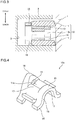
- FIG. 2 is a perspective view showing a part of a spacer expander used in the combined oil ring of the embodiment of the present invention.
- FIG. 3 is a cross-sectional view of a main part of an internal combustion engine to which a combined oil ring of another embodiment of the present invention is assembled, the cross-sectional view cut in the direction of a cylinder axis of the internal combustion engine.
- FIG. 1 is a cross-sectional view of a main part of an internal combustion engine to which a combined oil ring of an embodiment of the present invention is assembled, the cross-sectional view cut in the direction of a cylinder axis of the internal combustion engine.
- FIG. 4 is a perspective view showing a part of a spacer expander used in the combined oil ring of the other embodiment of the present invention.
- FIG. 5 shows cross-sectional views of side rails used in the combined oil ring of the embodiment of the present invention, the cross-sectional views cut in the direction of the cylinder axis of the internal combustion engine.
- FIG. 6 is a diagram of modifications of a front and back detection means of the combined oil ring of the embodiment of the present invention.
- FIG. 7 is a cross-sectional view of a main part of a modification of the combined oil ring of the embodiment of the present invention.
- FIG. 8 is a graph showing oil consumption by the combined oil ring of the embodiment of the present invention. Note that in the specification, the vertical direction is defined as a direction extending along upper and lower directions of the sheet in FIGS. 1 and 3 .
- a combined oil ring 10 of the embodiment is assembled in an oil ring groove 3 formed on an outer circumferential surface of a piston 2 of an internal combustion engine, and is a member that comes into sliding contact with an inner wall of a cylinder 1 and scrapes off excess engine oil attached to the inner wall of the cylinder 1, to thereby form an appropriate oil film on the inner wall of the cylinder 1.
- the combined oil ring 10 is configured of a pair of upper and lower side rails 11, 11, and a spacer expander 12 arranged between the pair of upper and lower side rails 11, 11.
- the side rails 11, 11 and the spacer expander 12 are made of steel, for example, and each side rails 11 is formed as a flat annular ring including a gap (not shown).
- the spacer expander 12 is formed by performing deformation processing on a steel material, has an irregular shape (corrugated shape) along the axial direction, and is formed into a substantially circular shape in the circumferential direction.
- the irregular shape in the axial direction forms upper pieces 13 and lower pieces 14 in an axial end part.
- the spacer expander 12 includes many upper pieces 13 and lower pieces 14 spaced apart from one another in axial and circumferential directions, and arranged alternately in the circumferential direction.
- a coupling piece 15 couples an upper piece 13 with an adjacent lower piece 14.
- ear portions 16 respectively pushing the side rails 11, 11 to the outer circumferential side are each formed in such a manner as to stand in an arch shape in an inner circumferential end part of each of the upper piece 13 and the lower piece 14 of the spacer expander 12.
- a through hole 18 is formed along the radial direction in the ear portion 16.
- a groove 17 is formed along the radial direction on each of an upper surface of the upper piece 13 and a lower surface (not shown) of the lower piece 14. Additionally, a side rail support portion 19 formed a step higher than the groove 17 is provided, in an outer circumferential end part of each of the upper piece 13 and the lower piece 14 of the spacer expander 12.
- a spacer expander 12a may have, in a groove 17, a recess 17a whose cross-sectional shape along the radial direction is V-shaped or R-shaped.
- the recess 17a increases the opening area of a through hole 18, it is possible to increase the flow rate of oil flowing through the through hole 18.
- the spacer expander 12 when the spacer expander 12 is assembled in the oil ring groove 3 of the piston 2, the spacer expander 12 is compressed in the circumferential direction with ends of the gap brought into contact with each other. Accordingly, the spacer expander 12 is assembled such that tension of the spacer expander 12 generates a radially outward expansion force.
- the side rail support portions 19, 19 of the upper pieces 13 and the lower pieces 14 separate the upper and lower side rails 11, 11 to upper and lower sides in the axial direction and hold them, while the ear portions 16 respectively push inner circumferential surfaces of the side rails 11 to bring outer circumferential surfaces of the upper and lower side rails 11, 11 into close contact with an inner wall surface of the cylinder 1.
- the upper side rail 11 of the pair of upper and lower side rails includes a slide contact part that comes into sliding contact with the cylinder.
- the cross-sectional shape of the slide contact part along the axial direction of the piston 1 includes: a tapered shape in which a side surface 23 spreads linearly from a side rail-upper surface 21 to a side rail-lower surface 22; and a curved surface 24 curving at a predetermined curvature.
- a vertex 24a is formed at the radially outermost end on the curved surface 24. Note that the vertex 24a is formed where a height H from the lower surface 22 of the side rail 11 is within 0.15 mm.
- the curvature of the curved surface 24 is preferably set to R0.01 to 0.5 (mm).
- the combined oil ring 10 is assembled such that the pair of upper and lower side rails 11, 11 are facing the same direction. Specifically, the pair of upper and lower side rails 11, 11 are both combined with the spacer expander 12 such that the vertex 24a is positioned on the lower end side, and thereby constitute the combined oil ring 10.
- a recess 25 as a front and back detection means may be formed on the side rail-upper surface 21. Since the recess 25 only needs to be capable of being detected by the side rail-upper surface 21, the recess 25 may be formed into an annular shape or a dot on the side rail-upper surface 11. Note that the recess 25 may be formed by pressing, punching, or laser cutting the side rail, or may be formed at the same time as a wire drawing process such as roll drawing and die drawing, for example. Moreover, instead of providing the recess 25, paint may be applied in an interrupted or continuous manner on the side rail-upper surface 21 or lower surface 22.
- the surface roughness of any one of the upper surface 21 and the lower surface 22 may be varied by smoothening the upper surface 21 and roughening the lower surface 22, for example, to detect the front and back by touching. In this case, since the detection does not depend on sight, it is possible to surely detect the front and back, even when there is not enough light in the workplace.
- the side surface 23 is tilted at a predetermined angle ⁇ with respect to a central axis C of the spacer expander 12.
- the angle ⁇ is preferably set to 5 to 30 degrees, and more preferably set to 8 to 12 degrees.
- paint 26 may be applied on any one of the right and left of a gap 30 of a side surface 23 of a side rail. With this, it is possible to detect the front and back of the side rail, by always assembling the side rail such that the paint 26 is placed on the right side of the gap 30, for example.
- both sides of a gap 30 may be painted with first paint 26a applied on one side, and second paint 26b in a color different from the first paint 26a applied on the other side. If the first paint 26a is white and the second paint 26b is red, for example, it is possible to detect the front and back of a side rail, by assembling the side rail such that white is placed on the right.
- a chamfering 27 may be provided on one of inner circumferential end parts of a gap 30 on an end opposite to a side surface 23. With this, it is possible to detect the front and back of the side rail, by assembling the side rail such that the chamfering 27 is placed on the right side of the gap 30, for example.
- the pair of upper and lower side rails may be formed such that an upper side rail 11 has a tapered shape, and an axial cross-section of a lower side rail 11' is a barrel shape that is formed into an arc form protruding in the radial direction.
- the barrel shape can be assembled to the combined oil ring without detecting the front and back thereof, it is possible to lighten the workload of the aforementioned front-back detection.
- a functional test was performed for the combined oil ring 10 of the embodiment by use of an example and a comparative example, to describe the present invention in more detail.
- the functional test was performed by using a 2.4 L inline-four gasoline car engine.
- oil consumption (LOC) was measured for a conventional example (barrel shape) and the combined oil ring of the present invention at WOT (wide open throttle), so that the piston speed was 16 m/s to 23 m/s, and the results were verified by relative ratios where the value of the conventional example at 22.6 m/s is 1.
- An ion plating film made of Cr-N was formed on slide contact surfaces of a top compression ring and side rails of an oil ring. After forming the ion plating film on each of the slide contact surfaces of the oil ring, lapping was performed thereon to smoothen projection parts and tapered parts on the slide contact surface.
- the position of a vertex 24a of a curved surface 24 was not more than 0.15 mm from a side rail-lower surface 22.
- the side rails of the combined oil ring 10 of the above-mentioned embodiments may be surface-treated with DLC (Diamond Like Carbon), for example.
- DLC Diamond Like Carbon
- a pattern may be provided on any one of the side rail-upper surface 21 and the side rail-lower surface 22.
Landscapes
- Engineering & Computer Science (AREA)
- General Engineering & Computer Science (AREA)
- Mechanical Engineering (AREA)
- Chemical & Material Sciences (AREA)
- Combustion & Propulsion (AREA)
- Pistons, Piston Rings, And Cylinders (AREA)
Abstract
Description
- The present invention relates to a combined oil ring, and particularly to a three-piece combined oil ring including a pair of upper and lower side rails and a spacer expander arranged therebetween.
- A conventionally known oil ring scrapes off excess engine oil attached to a cylinder inner wall surface of an internal combustion engine, and forms an appropriate oil film, to thereby prevent seizure of a piston resulting from operation of the internal combustion engine, and reduce wear of a slide contact surface between the oil ring and the cylinder. Various forms of such an oil ring have been known. For example, the following Patent Literature describes a combined oil ring including a pair of upper and lower side rails and a spacer expander arranged therebetween, in which working surfaces of the side rails, in cross-section, follow the asymmetrical shape of a polynomial of the second order in a first segment, with h(x)=ax+bx2, and after passing a supporting vertex h(x) configured as an edge, in a third segment follow the asymmetrical shape of the function h(x)=cx2, with c as a multiple of b.
- Patent Literature 1: National Publication of International Patent Application No.
2007-504416 - Additionally, as mentioned above, the combined oil ring scrapes off excess engine oil attached to a cylinder inner wall surface of an internal combustion engine, and forms an appropriate oil film, to thereby prevent seizure of a piston. However, since the engine oil attached to a combustion chamber of the internal combustion engine is burnt and discharged to the outside of the internal combustion engine as exhaust gas, it is necessary to surely scrape off excess engine oil while maintaining the sealing performance of a piston ring, to reduce oil consumption.
- Even though the shape of slide contact surfaces of side rails and the tension of piston rings are variously set in conventional combined oil rings to improve their ability of scraping off engine oil, there is an increasing demand for further reduction in oil consumption in the context of lower energy consumption and environmental issues. However, according to the shape of the oil ring described in the
aforementioned Patent Literature 1, the contact area increases in the initial stage of the sliding contact. Hence, the engine oil scraping function cannot be fully exerted in some cases. - The present invention has been made in view of the above problem, and aims to provide a combined oil ring that further reduces engine oil consumption.
- The combined oil ring of the present invention is attached to an oil ring groove of a piston and includes: a pair of upper and lower side rails each formed into a flat annular shape, and having a slide contact part that comes into sliding contact with a cylinder; and a spacer expander arranged between the pair of upper and lower side rails. The combined oil ring is characterized in that: in at least the upper side rail of the pair of upper and lower side rails, a cross-sectional shape of the slide contact part along an axial direction of the piston is a tapered shape linearly spreading from upper to lower parts of the piston; the tapered shape is at an angle of 5 to 30 degrees with respect to a central axis of the spacer expander, and has a vertex of the tapered shape within 0.15 mm from a lower end of the side rail; and a part closer to the lower end than the vertex is formed into a curved shape having a curvature of R0.01 to 0.5.
- Also, in the combined oil ring of the present invention, it is preferable that in the lower side rail of the pair of upper and lower side rails, a cross-sectional shape of the slide contact part along the axial direction of the piston be a tapered shape linearly spreading from upper to lower parts of the piston.
- Also, in the combined oil ring of the present invention, it is preferable that a cross-sectional shape of the lower side rail of the pair of upper and lower side rails along the axial direction of the piston be a barrel shape that is formed into an arc form.
- Also, in the combined oil ring of the present invention, it is preferable that the pair of upper and lower side rails include a front and back detection means.
- Also, in the combined oil ring of the present invention, it is preferable that at least one of the pair of upper and lower side rails and the spacer expander be subjected to surface treatment.
- In the combined oil ring of the present invention, a cross-sectional shape of at least the upper side rail of the pair of upper and lower side rails along an axial direction of the piston is a tapered shape linearly spreading from upper to lower parts of the piston; the tapered shape is at an angle of 5 to 30 degrees with respect to a central axis of the spacer expander, and has a vertex of the tapered shape within 0.15 mm from a lower end of the side rail; and a part closer to the lower end than the vertex is formed into a curved shape having a curvature of R0.01 to 0.5. Hence, oil consumption can be reduced further.
- Also, in the combined oil ring of the present invention, in the lower side rail of the pair of upper and lower side rails, a cross-sectional shape of the slide contact part along the axial direction of the piston is a tapered shape linearly spreading from upper to lower parts of the piston. Hence, oil consumption can be reduced even more.
- Also, in the combined oil ring of the present invention, a cross-sectional shape of the lower side rail of the pair of upper and lower side rails along the axial direction of the piston is a barrel shape that is formed into an arc form. Hence, it is possible to assemble the lower side rail without detecting the front or back thereof, and eliminate the complicated work of front-back detection.
- Also, in the combined oil ring of the present invention, the pair of upper and lower side rails include the front-back detection means. Hence, when assembling the combined oil ring and installing the combined oil ring into the piston groove, it is possible to prevent erroneous installation due to mistaking of the front and back, and prevent increased oil consumption due to erroneous installation.
- Also, in the combined oil ring of the present invention, the pair of upper and lower side rails are subjected to surface treatment. Hence, it is possible to reduce sliding resistance between the pair of upper and lower side rails and the cylinder, and suppress wear of the combined oil ring.
-
- [
FIG. 1] FIG. 1 is a cross-sectional view of a main part of an internal combustion engine into which a combined oil ring of an embodiment of the present invention is assembled, the cross-sectional view cut in the direction of a cylinder axis of the internal combustion engine. - [
FIG. 2] FIG. 2 is a perspective view showing a part of a spacer expander used in the combined oil ring of the embodiment of the present invention. - [
FIG. 3] FIG. 3 is a cross-sectional view of a main part of an internal combustion engine to which a combined oil ring of another embodiment of the present invention is assembled, the cross-sectional view cut in the direction of a cylinder axis of the internal combustion engine. - [
FIG. 4] FIG. 4 is a perspective view showing a part of a spacer expander used in the combined oil ring of the other embodiment of the present invention. - [
FIG. 5] FIG. 5 shows cross-sectional views of side rails used in the combined oil ring of the embodiment of the present invention, the cross-sectional views cut in the direction of the cylinder axis of the internal combustion engine. - [
FIG. 6] FIG. 6 is a diagram of modifications of a front and back detection means of the combined oil ring of the embodiment of the present invention. - [
FIG. 7] FIG. 7 is a cross-sectional view of a main part of a modification of the combined oil ring of the embodiment of the present invention. - [
FIG. 8] FIG. 8 is a graph showing oil consumption by the combined oil ring of the embodiment of the present invention. - Hereinafter, preferred embodiments for carrying out the present invention will be described with reference to the drawings. Note that the following embodiments do not limit aspects of the invention according to the claims, and not all of combinations of characteristics described in the embodiments are essential to solutions provided by the invention.
-
FIG. 1 is a cross-sectional view of a main part of an internal combustion engine to which a combined oil ring of an embodiment of the present invention is assembled, the cross-sectional view cut in the direction of a cylinder axis of the internal combustion engine.FIG. 2 is a perspective view showing a part of a spacer expander used in the combined oil ring of the embodiment of the present invention.FIG. 3 is a cross-sectional view of a main part of an internal combustion engine to which a combined oil ring of another embodiment of the present invention is assembled, the cross-sectional view cut in the direction of a cylinder axis of the internal combustion engine.FIG. 4 is a perspective view showing a part of a spacer expander used in the combined oil ring of the other embodiment of the present invention.FIG. 5 shows cross-sectional views of side rails used in the combined oil ring of the embodiment of the present invention, the cross-sectional views cut in the direction of the cylinder axis of the internal combustion engine.FIG. 6 is a diagram of modifications of a front and back detection means of the combined oil ring of the embodiment of the present invention.FIG. 7 is a cross-sectional view of a main part of a modification of the combined oil ring of the embodiment of the present invention.FIG. 8 is a graph showing oil consumption by the combined oil ring of the embodiment of the present invention. Note that in the specification, the vertical direction is defined as a direction extending along upper and lower directions of the sheet inFIGS. 1 and3 . - As shown in
FIG. 1 , a combinedoil ring 10 of the embodiment is assembled in anoil ring groove 3 formed on an outer circumferential surface of apiston 2 of an internal combustion engine, and is a member that comes into sliding contact with an inner wall of acylinder 1 and scrapes off excess engine oil attached to the inner wall of thecylinder 1, to thereby form an appropriate oil film on the inner wall of thecylinder 1. - The combined
oil ring 10 is configured of a pair of upper andlower side rails lower side rails side rails side rails 11 is formed as a flat annular ring including a gap (not shown). - As shown in
FIG. 2 , thespacer expander 12 is formed by performing deformation processing on a steel material, has an irregular shape (corrugated shape) along the axial direction, and is formed into a substantially circular shape in the circumferential direction. The irregular shape in the axial direction formsupper pieces 13 andlower pieces 14 in an axial end part. Specifically, the spacer expander 12 includes manyupper pieces 13 andlower pieces 14 spaced apart from one another in axial and circumferential directions, and arranged alternately in the circumferential direction. Acoupling piece 15 couples anupper piece 13 with an adjacentlower piece 14. - In addition, as shown in
FIG. 1 ,ear portions 16 respectively pushing theside rails upper piece 13 and thelower piece 14 of the spacer expander 12. Note that as shown inFIG. 2 , athrough hole 18 is formed along the radial direction in theear portion 16. - Furthermore, as shown in
FIG. 2 , agroove 17 is formed along the radial direction on each of an upper surface of theupper piece 13 and a lower surface (not shown) of thelower piece 14. Additionally, a siderail support portion 19 formed a step higher than thegroove 17 is provided, in an outer circumferential end part of each of theupper piece 13 and thelower piece 14 of the spacer expander 12. - Note that as shown in
FIGS. 3 and 4 , aspacer expander 12a may have, in agroove 17, arecess 17a whose cross-sectional shape along the radial direction is V-shaped or R-shaped. In this case, since therecess 17a increases the opening area of a throughhole 18, it is possible to increase the flow rate of oil flowing through the throughhole 18. - Thus, by forming the
groove 17 in thespacer expander 12a, it is possible to smoothly circulate engine oil from the outer circumferential side to the inner circumferential side of the piston. With this, the engine oil scraped off by the piston ring can be circulated back into the engine, and also be kept from leaking into the combustion chamber, so that oil consumption (LOC) can be reduced. - Note that when the
spacer expander 12 is assembled in theoil ring groove 3 of thepiston 2, thespacer expander 12 is compressed in the circumferential direction with ends of the gap brought into contact with each other. Accordingly, thespacer expander 12 is assembled such that tension of thespacer expander 12 generates a radially outward expansion force. Hence, the siderail support portions upper pieces 13 and thelower pieces 14 separate the upper and lower side rails 11, 11 to upper and lower sides in the axial direction and hold them, while theear portions 16 respectively push inner circumferential surfaces of the side rails 11 to bring outer circumferential surfaces of the upper and lower side rails 11, 11 into close contact with an inner wall surface of thecylinder 1. - As shown in
FIG. 5(a) , at least theupper side rail 11 of the pair of upper and lower side rails includes a slide contact part that comes into sliding contact with the cylinder. The cross-sectional shape of the slide contact part along the axial direction of thepiston 1 includes: a tapered shape in which aside surface 23 spreads linearly from a side rail-upper surface 21 to a side rail-lower surface 22; and acurved surface 24 curving at a predetermined curvature. In addition, in the cross-sectional shape, avertex 24a is formed at the radially outermost end on thecurved surface 24. Note that thevertex 24a is formed where a height H from thelower surface 22 of theside rail 11 is within 0.15 mm. Moreover, the curvature of thecurved surface 24 is preferably set to R0.01 to 0.5 (mm). - Note that as shown in
FIG. 1 , the combinedoil ring 10 is assembled such that the pair of upper and lower side rails 11, 11 are facing the same direction. Specifically, the pair of upper and lower side rails 11, 11 are both combined with thespacer expander 12 such that thevertex 24a is positioned on the lower end side, and thereby constitute the combinedoil ring 10. - Furthermore, as shown in
FIG. 5(b) , arecess 25 as a front and back detection means may be formed on the side rail-upper surface 21. Since therecess 25 only needs to be capable of being detected by the side rail-upper surface 21, therecess 25 may be formed into an annular shape or a dot on the side rail-upper surface 11. Note that therecess 25 may be formed by pressing, punching, or laser cutting the side rail, or may be formed at the same time as a wire drawing process such as roll drawing and die drawing, for example. Moreover, instead of providing therecess 25, paint may be applied in an interrupted or continuous manner on the side rail-upper surface 21 orlower surface 22. Instead, the surface roughness of any one of theupper surface 21 and thelower surface 22 may be varied by smoothening theupper surface 21 and roughening thelower surface 22, for example, to detect the front and back by touching. In this case, since the detection does not depend on sight, it is possible to surely detect the front and back, even when there is not enough light in the workplace. Note that theside surface 23 is tilted at a predetermined angle θ with respect to a central axis C of thespacer expander 12. The angle θ is preferably set to 5 to 30 degrees, and more preferably set to 8 to 12 degrees. - Further, as shown in
FIG. 6(a) , various forms are applicable as the front-back detection means. For example, paint 26 may be applied on any one of the right and left of agap 30 of aside surface 23 of a side rail. With this, it is possible to detect the front and back of the side rail, by always assembling the side rail such that thepaint 26 is placed on the right side of thegap 30, for example. - Also, as shown in
FIG. 6(b) , both sides of agap 30 may be painted withfirst paint 26a applied on one side, andsecond paint 26b in a color different from thefirst paint 26a applied on the other side. If thefirst paint 26a is white and thesecond paint 26b is red, for example, it is possible to detect the front and back of a side rail, by assembling the side rail such that white is placed on the right. - Also, as shown in
FIG. 6(c) , achamfering 27 may be provided on one of inner circumferential end parts of agap 30 on an end opposite to aside surface 23. With this, it is possible to detect the front and back of the side rail, by assembling the side rail such that thechamfering 27 is placed on the right side of thegap 30, for example. - Also, as shown in
FIG. 7 , the pair of upper and lower side rails may be formed such that anupper side rail 11 has a tapered shape, and an axial cross-section of a lower side rail 11' is a barrel shape that is formed into an arc form protruding in the radial direction. In this case, since the barrel shape can be assembled to the combined oil ring without detecting the front and back thereof, it is possible to lighten the workload of the aforementioned front-back detection. - Next, a functional test was performed for the combined
oil ring 10 of the embodiment by use of an example and a comparative example, to describe the present invention in more detail. The functional test was performed by using a 2.4 L inline-four gasoline car engine. As test conditions, oil consumption (LOC) was measured for a conventional example (barrel shape) and the combined oil ring of the present invention at WOT (wide open throttle), so that the piston speed was 16 m/s to 23 m/s, and the results were verified by relative ratios where the value of the conventional example at 22.6 m/s is 1. - An ion plating film made of Cr-N was formed on slide contact surfaces of a top compression ring and side rails of an oil ring. After forming the ion plating film on each of the slide contact surfaces of the oil ring, lapping was performed thereon to smoothen projection parts and tapered parts on the slide contact surface. The position of a
vertex 24a of acurved surface 24 was not more than 0.15 mm from a side rail-lower surface 22. - Note that other test conditions were as follows.
- Piston bore diameter: 87 mm,
- shape of slide contact surface of top compression ring: barrel-faced, and
- shape of slide contact surface of second compression ring: tapered and undercut.
- In the test, side rails 11 formed as in
FIG. 5(a) , and a spacer expander formed as inFIG. 2 were used as an example. Dimensions of the oil ring were as follows. - EA of spacer expander: 10 degrees,
- radial thickness of side rail: 1.9 mm,
- axial thickness of side rail: 0.4 mm,
- outer angle θ of side rail: 10 degrees, and
- axial width of oil ring: 2.0 mm.
- As shown in
FIG. 8 , it has been verified that when compared with the comparative example at piston speeds of 22 m/s and 22.6 m/s, the example reduced oil consumption by approximately 40% from conventional one. - Note that while placement of the vertices of the pair of side rails on the lower side as in the example reduces oil consumption significantly, it has been verified that placement of the vertices of the side rails on the upper side causes frequent scraping up of oil, and therefore increases oil consumption.
- Thus, by comparing oil consumption by the conventional combined oil ring using the barrel-shaped side rail and oil consumption by the combined
oil ring 10 of the embodiment, it has been verified that the shape of the embodiment has an effect of suppressing oil consumption by approximately 40%. - Additionally, the side rails of the combined
oil ring 10 of the above-mentioned embodiments may be surface-treated with DLC (Diamond Like Carbon), for example. Also, as the front-back detection means, in addition to forming therecess 25 as inFIG. 5(b) , a pattern may be provided on any one of the side rail-upper surface 21 and the side rail-lower surface 22. It is clear from the description of the scope of claims, that such modified or improved forms may be included in the technical scope of the present invention. -
- 1 cylinder, 2 piston, 3 oil ring groove, 10 combined oil ring, 11 side rail, 12 spacer expander, 21 side rail-upper surface, 22 side rail-lower surface,
- 23 side surface, 24
curved surface 24a vertex, - 25 recess.
Claims (5)
- A combined oil ring attached to an oil ring groove of a piston, comprising:a pair of upper and lower side rails each formed into a flat annular shape, and having a slide contact part that comes into sliding contact with a cylinder; anda spacer expander arranged between the pair of upper and lower side rails, wherein:in at least the upper side rail of the pair of upper and lower side rails, a cross-sectional shape of the slide contact part along an axial direction of the piston is a tapered shape linearly spreading from upper to lower parts of the piston;the tapered shape is at an angle of 5 to 30 degrees with respect to a central axis of the spacer expander, and has a vertex of the tapered shape within 0.15 mm from a lower end of the side rail; anda part closer to the lower end than the vertex is formed into a curved shape having a curvature of R0.01 to 0.5.
- The combined oil ring according to claim 1, wherein
in the lower side rail of the pair of upper and lower side rails, a cross-sectional shape of the slide contact part along the axial direction of the piston is a tapered shape linearly spreading from upper to lower parts of the piston. - The combined oil ring according to claim 1, wherein
a cross-sectional shape of the lower side rail of the pair of upper and lower side rails along the axial direction of the piston is a barrel shape that is formed into an arc form. - The combined oil ring according to any one of claims 1 to 3, wherein
the pair of upper and lower side rails include a front and back detection means. - The combined oil ring according to any one of claims 1 to 4, wherein
at least one of the pair of upper and lower side rails and the spacer expander is subjected to surface treatment.
Applications Claiming Priority (3)
| Application Number | Priority Date | Filing Date | Title |
|---|---|---|---|
| JP2014157068 | 2014-07-31 | ||
| JP2015085042A JP6122901B2 (en) | 2014-07-31 | 2015-04-17 | Combination oil ring |
| PCT/JP2015/070831 WO2016017499A1 (en) | 2014-07-31 | 2015-07-22 | Combination oil ring |
Publications (3)
| Publication Number | Publication Date |
|---|---|
| EP3176474A1 true EP3176474A1 (en) | 2017-06-07 |
| EP3176474A4 EP3176474A4 (en) | 2018-04-25 |
| EP3176474B1 EP3176474B1 (en) | 2020-03-18 |
Family
ID=55217400
Family Applications (1)
| Application Number | Title | Priority Date | Filing Date |
|---|---|---|---|
| EP15826536.3A Active EP3176474B1 (en) | 2014-07-31 | 2015-07-22 | Combination oil ring |
Country Status (5)
| Country | Link |
|---|---|
| US (1) | US10724636B2 (en) |
| EP (1) | EP3176474B1 (en) |
| JP (1) | JP6122901B2 (en) |
| CN (1) | CN106471292A (en) |
| WO (1) | WO2016017499A1 (en) |
Cited By (1)
| Publication number | Priority date | Publication date | Assignee | Title |
|---|---|---|---|---|
| EP3430290B1 (en) | 2016-03-16 | 2020-06-17 | Federal-Mogul Burscheid GmbH | Multiple-piece oil stripping piston ring with reduced friction |
Families Citing this family (7)
| Publication number | Priority date | Publication date | Assignee | Title |
|---|---|---|---|---|
| US10253882B2 (en) * | 2013-12-30 | 2019-04-09 | Mahle International Gmbh | Oil control ring assembly |
| EP3279525B1 (en) | 2015-03-31 | 2022-09-07 | Nippon Piston Ring Co., Ltd. | Combined oil ring |
| JP6695663B2 (en) * | 2015-07-09 | 2020-05-20 | 株式会社リケン | Piston rings for internal combustion engines |
| CN109416124B (en) | 2017-07-05 | 2020-04-14 | 帝伯爱尔株式会社 | Combined oil ring |
| JP6251850B1 (en) * | 2017-07-05 | 2017-12-20 | Tpr株式会社 | Combination oil ring |
| JP6603284B2 (en) * | 2017-10-05 | 2019-11-06 | 株式会社リケン | side rail |
| CN117006245A (en) * | 2019-02-01 | 2023-11-07 | 日本活塞环株式会社 | Combined oil ring |
Family Cites Families (17)
| Publication number | Priority date | Publication date | Assignee | Title |
|---|---|---|---|---|
| US2291876A (en) * | 1939-12-06 | 1942-08-04 | Charles C Wenkel | Piston ring |
| US3281156A (en) * | 1963-12-12 | 1966-10-25 | Ramsey Corp | Piston ring assembly |
| US5195758A (en) * | 1991-11-19 | 1993-03-23 | Hastings Manufacturing Company | Three-piece oil control ring assembly |
| JPH08247289A (en) * | 1995-03-13 | 1996-09-24 | Riken Corp | Combined three-piece oil ring |
| JP2002323133A (en) * | 2001-02-23 | 2002-11-08 | Teikoku Piston Ring Co Ltd | Wire for pressure ring, pressure ring and method of making the same |
| JP2003049705A (en) * | 2001-08-03 | 2003-02-21 | Nippon Piston Ring Co Ltd | One-ring structured piston for internal combustion engine |
| JP4132815B2 (en) * | 2001-12-28 | 2008-08-13 | 株式会社リケン | Side rail and combination oil ring |
| DE10340312A1 (en) * | 2003-09-02 | 2005-05-12 | Mahle Gmbh | Multi-piece oil scraper ring for pistons of internal combustion engines |
| BRPI0605175B1 (en) * | 2006-12-05 | 2020-01-21 | Mahle Metal Leve S/A | piston ring for internal combustion engines |
| DE102007027815A1 (en) * | 2007-06-13 | 2008-12-24 | Federal-Mogul Burscheid Gmbh | Oil ring |
| BR112012008116A2 (en) * | 2009-10-06 | 2017-10-10 | Kk Riken | internal combustion engine oil ring |
| AT508782B1 (en) * | 2010-02-15 | 2011-04-15 | Hoerbiger Kompressortech Hold | CIRCUIT ARRANGEMENT AND COMPRESSOR WITH SUCH A CUT-OFF ARRANGEMENT |
| US20110204575A1 (en) * | 2010-02-24 | 2011-08-25 | Mahle Konig Kommanditgesellschaft Gmbh & Co. | Piston ring |
| JP5557562B2 (en) * | 2010-03-10 | 2014-07-23 | Tpr株式会社 | Combination oil ring |
| EP2693085B1 (en) * | 2011-03-31 | 2018-10-10 | Kabushiki Kaisha Riken | Multi-piece oil ring |
| US20130154196A1 (en) * | 2011-12-14 | 2013-06-20 | Mahle International Gmbh | Piston ring formed from ring blank |
| JP2014209018A (en) * | 2012-08-30 | 2014-11-06 | 日本ピストンリング株式会社 | Combination oil ring |
-
2015
- 2015-04-17 JP JP2015085042A patent/JP6122901B2/en active Active
- 2015-07-22 WO PCT/JP2015/070831 patent/WO2016017499A1/en active Application Filing
- 2015-07-22 CN CN201580032842.8A patent/CN106471292A/en active Pending
- 2015-07-22 EP EP15826536.3A patent/EP3176474B1/en active Active
- 2015-07-22 US US15/329,282 patent/US10724636B2/en active Active
Cited By (2)
| Publication number | Priority date | Publication date | Assignee | Title |
|---|---|---|---|---|
| EP3430290B1 (en) | 2016-03-16 | 2020-06-17 | Federal-Mogul Burscheid GmbH | Multiple-piece oil stripping piston ring with reduced friction |
| EP3430290B2 (en) † | 2016-03-16 | 2023-06-28 | Federal-Mogul Burscheid GmbH | Multiple-piece oil stripping piston ring with reduced friction |
Also Published As
| Publication number | Publication date |
|---|---|
| JP6122901B2 (en) | 2017-04-26 |
| CN106471292A (en) | 2017-03-01 |
| US10724636B2 (en) | 2020-07-28 |
| JP2016035326A (en) | 2016-03-17 |
| EP3176474B1 (en) | 2020-03-18 |
| US20170227126A1 (en) | 2017-08-10 |
| EP3176474A4 (en) | 2018-04-25 |
| WO2016017499A1 (en) | 2016-02-04 |
Similar Documents
| Publication | Publication Date | Title |
|---|---|---|
| EP3176474B1 (en) | Combination oil ring | |
| CN107407412B (en) | Side rail | |
| US11873780B2 (en) | Combined oil ring | |
| JP6530200B2 (en) | side rail | |
| US20110309586A1 (en) | Compression piston ring | |
| WO2017164160A1 (en) | Combined oil control ring | |
| US20060273525A1 (en) | Multipart oil wiping ring for pistons of internal combustion engines | |
| JP6817374B2 (en) | piston ring | |
| US11448317B2 (en) | Side rail | |
| JP6762657B2 (en) | side rail | |
| JP6695663B2 (en) | Piston rings for internal combustion engines | |
| JP6385700B2 (en) | Oil ring | |
| US20160123466A1 (en) | Piston ring | |
| JP6659892B2 (en) | side rail | |
| EP3205909B1 (en) | Oil ring | |
| WO2018198173A1 (en) | Side rail |
Legal Events
| Date | Code | Title | Description |
|---|---|---|---|
| STAA | Information on the status of an ep patent application or granted ep patent |
Free format text: STATUS: THE INTERNATIONAL PUBLICATION HAS BEEN MADE |
|
| 17P | Request for examination filed |
Effective date: 20170123 |
|
| AK | Designated contracting states |
Kind code of ref document: A1 Designated state(s): AL AT BE BG CH CY CZ DE DK EE ES FI FR GB GR HR HU IE IS IT LI LT LU LV MC MK MT NL NO PL PT RO RS SE SI SK SM TR |
|
| AX | Request for extension of the european patent |
Extension state: BA ME |
|
| PUAI | Public reference made under article 153(3) epc to a published international application that has entered the european phase |
Free format text: ORIGINAL CODE: 0009012 |
|
| STAA | Information on the status of an ep patent application or granted ep patent |
Free format text: STATUS: REQUEST FOR EXAMINATION WAS MADE |
|
| DAV | Request for validation of the european patent (deleted) | ||
| DAX | Request for extension of the european patent (deleted) | ||
| A4 | Supplementary search report drawn up and despatched |
Effective date: 20180322 |
|
| RIC1 | Information provided on ipc code assigned before grant |
Ipc: F16J 9/06 20060101AFI20180316BHEP Ipc: F02F 5/00 20060101ALI20180316BHEP Ipc: F16J 9/20 20060101ALI20180316BHEP |
|
| GRAP | Despatch of communication of intention to grant a patent |
Free format text: ORIGINAL CODE: EPIDOSNIGR1 |
|
| STAA | Information on the status of an ep patent application or granted ep patent |
Free format text: STATUS: GRANT OF PATENT IS INTENDED |
|
| INTG | Intention to grant announced |
Effective date: 20191016 |
|
| GRAS | Grant fee paid |
Free format text: ORIGINAL CODE: EPIDOSNIGR3 |
|
| GRAA | (expected) grant |
Free format text: ORIGINAL CODE: 0009210 |
|
| STAA | Information on the status of an ep patent application or granted ep patent |
Free format text: STATUS: THE PATENT HAS BEEN GRANTED |
|
| AK | Designated contracting states |
Kind code of ref document: B1 Designated state(s): AL AT BE BG CH CY CZ DE DK EE ES FI FR GB GR HR HU IE IS IT LI LT LU LV MC MK MT NL NO PL PT RO RS SE SI SK SM TR |
|
| REG | Reference to a national code |
Ref country code: GB Ref legal event code: FG4D |
|
| REG | Reference to a national code |
Ref country code: DE Ref legal event code: R096 Ref document number: 602015049116 Country of ref document: DE |
|
| REG | Reference to a national code |
Ref country code: AT Ref legal event code: REF Ref document number: 1246262 Country of ref document: AT Kind code of ref document: T Effective date: 20200415 Ref country code: IE Ref legal event code: FG4D |
|
| PG25 | Lapsed in a contracting state [announced via postgrant information from national office to epo] |
Ref country code: FI Free format text: LAPSE BECAUSE OF FAILURE TO SUBMIT A TRANSLATION OF THE DESCRIPTION OR TO PAY THE FEE WITHIN THE PRESCRIBED TIME-LIMIT Effective date: 20200318 Ref country code: NO Free format text: LAPSE BECAUSE OF FAILURE TO SUBMIT A TRANSLATION OF THE DESCRIPTION OR TO PAY THE FEE WITHIN THE PRESCRIBED TIME-LIMIT Effective date: 20200618 Ref country code: RS Free format text: LAPSE BECAUSE OF FAILURE TO SUBMIT A TRANSLATION OF THE DESCRIPTION OR TO PAY THE FEE WITHIN THE PRESCRIBED TIME-LIMIT Effective date: 20200318 |
|
| REG | Reference to a national code |
Ref country code: NL Ref legal event code: MP Effective date: 20200318 |
|
| PG25 | Lapsed in a contracting state [announced via postgrant information from national office to epo] |
Ref country code: HR Free format text: LAPSE BECAUSE OF FAILURE TO SUBMIT A TRANSLATION OF THE DESCRIPTION OR TO PAY THE FEE WITHIN THE PRESCRIBED TIME-LIMIT Effective date: 20200318 Ref country code: SE Free format text: LAPSE BECAUSE OF FAILURE TO SUBMIT A TRANSLATION OF THE DESCRIPTION OR TO PAY THE FEE WITHIN THE PRESCRIBED TIME-LIMIT Effective date: 20200318 Ref country code: LV Free format text: LAPSE BECAUSE OF FAILURE TO SUBMIT A TRANSLATION OF THE DESCRIPTION OR TO PAY THE FEE WITHIN THE PRESCRIBED TIME-LIMIT Effective date: 20200318 Ref country code: BG Free format text: LAPSE BECAUSE OF FAILURE TO SUBMIT A TRANSLATION OF THE DESCRIPTION OR TO PAY THE FEE WITHIN THE PRESCRIBED TIME-LIMIT Effective date: 20200618 Ref country code: GR Free format text: LAPSE BECAUSE OF FAILURE TO SUBMIT A TRANSLATION OF THE DESCRIPTION OR TO PAY THE FEE WITHIN THE PRESCRIBED TIME-LIMIT Effective date: 20200619 |
|
| REG | Reference to a national code |
Ref country code: LT Ref legal event code: MG4D |
|
| PG25 | Lapsed in a contracting state [announced via postgrant information from national office to epo] |
Ref country code: NL Free format text: LAPSE BECAUSE OF FAILURE TO SUBMIT A TRANSLATION OF THE DESCRIPTION OR TO PAY THE FEE WITHIN THE PRESCRIBED TIME-LIMIT Effective date: 20200318 |
|
| PG25 | Lapsed in a contracting state [announced via postgrant information from national office to epo] |
Ref country code: IS Free format text: LAPSE BECAUSE OF FAILURE TO SUBMIT A TRANSLATION OF THE DESCRIPTION OR TO PAY THE FEE WITHIN THE PRESCRIBED TIME-LIMIT Effective date: 20200718 Ref country code: SK Free format text: LAPSE BECAUSE OF FAILURE TO SUBMIT A TRANSLATION OF THE DESCRIPTION OR TO PAY THE FEE WITHIN THE PRESCRIBED TIME-LIMIT Effective date: 20200318 Ref country code: PT Free format text: LAPSE BECAUSE OF FAILURE TO SUBMIT A TRANSLATION OF THE DESCRIPTION OR TO PAY THE FEE WITHIN THE PRESCRIBED TIME-LIMIT Effective date: 20200812 Ref country code: LT Free format text: LAPSE BECAUSE OF FAILURE TO SUBMIT A TRANSLATION OF THE DESCRIPTION OR TO PAY THE FEE WITHIN THE PRESCRIBED TIME-LIMIT Effective date: 20200318 Ref country code: SM Free format text: LAPSE BECAUSE OF FAILURE TO SUBMIT A TRANSLATION OF THE DESCRIPTION OR TO PAY THE FEE WITHIN THE PRESCRIBED TIME-LIMIT Effective date: 20200318 Ref country code: EE Free format text: LAPSE BECAUSE OF FAILURE TO SUBMIT A TRANSLATION OF THE DESCRIPTION OR TO PAY THE FEE WITHIN THE PRESCRIBED TIME-LIMIT Effective date: 20200318 Ref country code: CZ Free format text: LAPSE BECAUSE OF FAILURE TO SUBMIT A TRANSLATION OF THE DESCRIPTION OR TO PAY THE FEE WITHIN THE PRESCRIBED TIME-LIMIT Effective date: 20200318 Ref country code: RO Free format text: LAPSE BECAUSE OF FAILURE TO SUBMIT A TRANSLATION OF THE DESCRIPTION OR TO PAY THE FEE WITHIN THE PRESCRIBED TIME-LIMIT Effective date: 20200318 |
|
| REG | Reference to a national code |
Ref country code: AT Ref legal event code: MK05 Ref document number: 1246262 Country of ref document: AT Kind code of ref document: T Effective date: 20200318 |
|
| REG | Reference to a national code |
Ref country code: DE Ref legal event code: R097 Ref document number: 602015049116 Country of ref document: DE |
|
| PLBE | No opposition filed within time limit |
Free format text: ORIGINAL CODE: 0009261 |
|
| STAA | Information on the status of an ep patent application or granted ep patent |
Free format text: STATUS: NO OPPOSITION FILED WITHIN TIME LIMIT |
|
| PG25 | Lapsed in a contracting state [announced via postgrant information from national office to epo] |
Ref country code: DK Free format text: LAPSE BECAUSE OF FAILURE TO SUBMIT A TRANSLATION OF THE DESCRIPTION OR TO PAY THE FEE WITHIN THE PRESCRIBED TIME-LIMIT Effective date: 20200318 Ref country code: AT Free format text: LAPSE BECAUSE OF FAILURE TO SUBMIT A TRANSLATION OF THE DESCRIPTION OR TO PAY THE FEE WITHIN THE PRESCRIBED TIME-LIMIT Effective date: 20200318 Ref country code: IT Free format text: LAPSE BECAUSE OF FAILURE TO SUBMIT A TRANSLATION OF THE DESCRIPTION OR TO PAY THE FEE WITHIN THE PRESCRIBED TIME-LIMIT Effective date: 20200318 Ref country code: ES Free format text: LAPSE BECAUSE OF FAILURE TO SUBMIT A TRANSLATION OF THE DESCRIPTION OR TO PAY THE FEE WITHIN THE PRESCRIBED TIME-LIMIT Effective date: 20200318 |
|
| 26N | No opposition filed |
Effective date: 20201221 |
|
| PG25 | Lapsed in a contracting state [announced via postgrant information from national office to epo] |
Ref country code: MC Free format text: LAPSE BECAUSE OF FAILURE TO SUBMIT A TRANSLATION OF THE DESCRIPTION OR TO PAY THE FEE WITHIN THE PRESCRIBED TIME-LIMIT Effective date: 20200318 Ref country code: PL Free format text: LAPSE BECAUSE OF FAILURE TO SUBMIT A TRANSLATION OF THE DESCRIPTION OR TO PAY THE FEE WITHIN THE PRESCRIBED TIME-LIMIT Effective date: 20200318 |
|
| REG | Reference to a national code |
Ref country code: CH Ref legal event code: PL |
|
| GBPC | Gb: european patent ceased through non-payment of renewal fee |
Effective date: 20200722 |
|
| REG | Reference to a national code |
Ref country code: BE Ref legal event code: MM Effective date: 20200731 |
|
| PG25 | Lapsed in a contracting state [announced via postgrant information from national office to epo] |
Ref country code: CH Free format text: LAPSE BECAUSE OF NON-PAYMENT OF DUE FEES Effective date: 20200731 Ref country code: GB Free format text: LAPSE BECAUSE OF NON-PAYMENT OF DUE FEES Effective date: 20200722 Ref country code: LU Free format text: LAPSE BECAUSE OF NON-PAYMENT OF DUE FEES Effective date: 20200722 Ref country code: LI Free format text: LAPSE BECAUSE OF NON-PAYMENT OF DUE FEES Effective date: 20200731 |
|
| PG25 | Lapsed in a contracting state [announced via postgrant information from national office to epo] |
Ref country code: BE Free format text: LAPSE BECAUSE OF NON-PAYMENT OF DUE FEES Effective date: 20200731 Ref country code: SI Free format text: LAPSE BECAUSE OF FAILURE TO SUBMIT A TRANSLATION OF THE DESCRIPTION OR TO PAY THE FEE WITHIN THE PRESCRIBED TIME-LIMIT Effective date: 20200318 |
|
| PG25 | Lapsed in a contracting state [announced via postgrant information from national office to epo] |
Ref country code: IE Free format text: LAPSE BECAUSE OF NON-PAYMENT OF DUE FEES Effective date: 20200722 |
|
| PG25 | Lapsed in a contracting state [announced via postgrant information from national office to epo] |
Ref country code: TR Free format text: LAPSE BECAUSE OF FAILURE TO SUBMIT A TRANSLATION OF THE DESCRIPTION OR TO PAY THE FEE WITHIN THE PRESCRIBED TIME-LIMIT Effective date: 20200318 Ref country code: MT Free format text: LAPSE BECAUSE OF FAILURE TO SUBMIT A TRANSLATION OF THE DESCRIPTION OR TO PAY THE FEE WITHIN THE PRESCRIBED TIME-LIMIT Effective date: 20200318 Ref country code: CY Free format text: LAPSE BECAUSE OF FAILURE TO SUBMIT A TRANSLATION OF THE DESCRIPTION OR TO PAY THE FEE WITHIN THE PRESCRIBED TIME-LIMIT Effective date: 20200318 |
|
| PG25 | Lapsed in a contracting state [announced via postgrant information from national office to epo] |
Ref country code: MK Free format text: LAPSE BECAUSE OF FAILURE TO SUBMIT A TRANSLATION OF THE DESCRIPTION OR TO PAY THE FEE WITHIN THE PRESCRIBED TIME-LIMIT Effective date: 20200318 Ref country code: AL Free format text: LAPSE BECAUSE OF FAILURE TO SUBMIT A TRANSLATION OF THE DESCRIPTION OR TO PAY THE FEE WITHIN THE PRESCRIBED TIME-LIMIT Effective date: 20200318 |
|
| P01 | Opt-out of the competence of the unified patent court (upc) registered |
Effective date: 20230509 |
|
| PGFP | Annual fee paid to national office [announced via postgrant information from national office to epo] |
Ref country code: FR Payment date: 20240611 Year of fee payment: 10 |
|
| PGFP | Annual fee paid to national office [announced via postgrant information from national office to epo] |
Ref country code: DE Payment date: 20240529 Year of fee payment: 10 |