EP3176457A1 - One-way clutch - Google Patents
One-way clutch Download PDFInfo
- Publication number
- EP3176457A1 EP3176457A1 EP16202021.8A EP16202021A EP3176457A1 EP 3176457 A1 EP3176457 A1 EP 3176457A1 EP 16202021 A EP16202021 A EP 16202021A EP 3176457 A1 EP3176457 A1 EP 3176457A1
- Authority
- EP
- European Patent Office
- Prior art keywords
- spring
- seat
- outer plate
- guide portions
- spring seat
- Prior art date
- Legal status (The legal status is an assumption and is not a legal conclusion. Google has not performed a legal analysis and makes no representation as to the accuracy of the status listed.)
- Granted
Links
- 230000007246 mechanism Effects 0.000 claims description 27
- 230000002093 peripheral effect Effects 0.000 abstract description 8
- 238000003754 machining Methods 0.000 abstract description 4
- 238000003825 pressing Methods 0.000 description 9
- 238000002788 crimping Methods 0.000 description 6
- 238000004080 punching Methods 0.000 description 5
- 229910000831 Steel Inorganic materials 0.000 description 4
- 238000005299 abrasion Methods 0.000 description 4
- 239000010959 steel Substances 0.000 description 4
- 239000002184 metal Substances 0.000 description 3
- 230000008859 change Effects 0.000 description 2
- 230000006872 improvement Effects 0.000 description 2
- 239000000463 material Substances 0.000 description 2
- 238000004519 manufacturing process Methods 0.000 description 1
- 238000000034 method Methods 0.000 description 1
- 230000004048 modification Effects 0.000 description 1
- 238000012986 modification Methods 0.000 description 1
Images


Classifications
-
- F—MECHANICAL ENGINEERING; LIGHTING; HEATING; WEAPONS; BLASTING
- F16—ENGINEERING ELEMENTS AND UNITS; GENERAL MEASURES FOR PRODUCING AND MAINTAINING EFFECTIVE FUNCTIONING OF MACHINES OR INSTALLATIONS; THERMAL INSULATION IN GENERAL
- F16D—COUPLINGS FOR TRANSMITTING ROTATION; CLUTCHES; BRAKES
- F16D41/00—Freewheels or freewheel clutches
- F16D41/06—Freewheels or freewheel clutches with intermediate wedging coupling members between an inner and an outer surface
-
- F—MECHANICAL ENGINEERING; LIGHTING; HEATING; WEAPONS; BLASTING
- F16—ENGINEERING ELEMENTS AND UNITS; GENERAL MEASURES FOR PRODUCING AND MAINTAINING EFFECTIVE FUNCTIONING OF MACHINES OR INSTALLATIONS; THERMAL INSULATION IN GENERAL
- F16D—COUPLINGS FOR TRANSMITTING ROTATION; CLUTCHES; BRAKES
- F16D41/00—Freewheels or freewheel clutches
- F16D41/12—Freewheels or freewheel clutches with hinged pawl co-operating with teeth, cogs, or the like
-
- F—MECHANICAL ENGINEERING; LIGHTING; HEATING; WEAPONS; BLASTING
- F16—ENGINEERING ELEMENTS AND UNITS; GENERAL MEASURES FOR PRODUCING AND MAINTAINING EFFECTIVE FUNCTIONING OF MACHINES OR INSTALLATIONS; THERMAL INSULATION IN GENERAL
- F16D—COUPLINGS FOR TRANSMITTING ROTATION; CLUTCHES; BRAKES
- F16D41/00—Freewheels or freewheel clutches
- F16D41/06—Freewheels or freewheel clutches with intermediate wedging coupling members between an inner and an outer surface
- F16D2041/0603—Sprag details
-
- F—MECHANICAL ENGINEERING; LIGHTING; HEATING; WEAPONS; BLASTING
- F16—ENGINEERING ELEMENTS AND UNITS; GENERAL MEASURES FOR PRODUCING AND MAINTAINING EFFECTIVE FUNCTIONING OF MACHINES OR INSTALLATIONS; THERMAL INSULATION IN GENERAL
- F16D—COUPLINGS FOR TRANSMITTING ROTATION; CLUTCHES; BRAKES
- F16D41/00—Freewheels or freewheel clutches
- F16D41/06—Freewheels or freewheel clutches with intermediate wedging coupling members between an inner and an outer surface
- F16D2041/0605—Spring details
Definitions
- the present invention relates to the structure of a one-way clutch and, more particularly, to improvement in the durability of a one-way clutch.
- a one-way clutch including an inner plate, an outer plate and ratchet mechanisms.
- the ratchet mechanisms permit relative rotation of these inner plate and outer plate in one direction, and stop relative rotation in the other direction.
- pawls pawl members
- the pawls function as ratchet mechanisms.
- the notches engage with the pawls at the time when the inner plate and the outer plate relatively rotate in the other direction.
- a spring is provided between the outer plate and each pawl, and presses the corresponding pawl toward the inner plate.
- the outer plate has pockets for accommodating the springs, and one end of each spring is in contact with a wall face formed by the corresponding one of the pockets.
- Each wall face formed by the corresponding pocket and with which one end of the corresponding spring contacts is flat.
- the pockets of the outer plate are usually formed by punching a metal sheet, so it is difficult to obtain sufficient accuracy even when each wall face is formed in a flat shape, and each wall face is actually formed in a circular arc shape. Therefore, one end of each spring contacts the face formed in a circular arc shape. In this case, the position of each spring is not stable.
- the one-way clutch works in a state where any one of the springs is seated in an inclined position, the spring, for example, interferes with a peripheral portion, and a load acts on the spring, with the result of a possibility of decrease in the durability of the one-way clutch.
- the present invention provides the structure of a one-way clutch that includes a ratchet mechanism and that improves the durability of the one-way clutch.
- An example aspect of the present invention provides a one-way clutch.
- the one-way clutch includes a first member, a second member and a ratchet mechanism.
- the first member is arranged around a rotation axis.
- the second member is arranged around the rotation axis so as to surround the first member.
- the ratchet mechanism is provided between the first member and the second member, the ratchet mechanism is configured to permit relative rotation between the first member and the second member in one direction.
- the ratchet mechanism is configured to stop relative rotation between the first member and the second member in the other direction.
- the ratchet mechanism includes a pawl, and a spring seat. The pawl is provided on one of the first member and the second member.
- the pawl is configured to pivot toward the other of the first member and the second member.
- the spring is provided between the pawl and the one of the first member and the second member.
- the spring is configured to press the pawl toward the other of the first member and the second member such that the pawl pivots toward the other of the first member and the second member, and a spring seat supports the spring.
- the spring is connected to the one of the first member and the second member via the spring seat the spring seat the spring seat includes a planar portion and a pair of guide portions.
- the planar portion has a planar shape for receiving one end of the spring.
- the pair of guide portions extends from the planar portion parallel in a direction in which the spring extends or contracts.
- the spring seat since one end of the spring is received by the planar portion of the spring seat, it is possible to support the spring with a planar member without machining the one of the first member and the second member into a planar shape. Since the spring seat has the guide portions that contact the one of the first member and the second member, it is possible to suppress the fluctuation of the spring seat and the fluctuation of the spring by the guide portions, so it is possible to reliably prevent interference of the spring with its peripheral portion. Therefore, a load on the spring is reduced, so it is possible to improve the durability of the one-way clutch.
- the one-way clutch may further be provided that the pair of guide portions of the spring seat may expand away from the spring at a position located a predetermined distance from the planar portion. At least part of portions of the pair of guide portions, is located the predetermined distance from the planar portion, are in contact with the one of the first member and the second member.
- the pair of guide portions of the spring seat expand away from the spring at a position located the predetermined distance from the planar portion, and at least part of the guide portions are in contact with the one of the first member and the second member, so force that suppresses the fluctuation of the spring seat acts on the spring seat between each of the portions of the guide portions, located the predetermined distance from the planar portion, and the one of the first member and the second member, with the result that the position of the spring seat is stable. Even when the spring bends, the guide portions are prevented from getting caught in between the steel wires of the spring.
- the one-way clutch may further be provided that the stiffness of the guide portions is lower than the stiffness of the spring.
- FIG. 1 shows the overall structure of a one-way clutch 10 according to an embodiment of the present invention.
- the one-way clutch 10 is, for example, provided on a crankshaft of an engine (not shown), and is used to, for example, prevent reverse rotation of the crankshaft.
- the one-way clutch 10 includes an inner plate 12, an outer plate 14, and a plurality of ratchet mechanisms 16.
- the plurality of ratchet mechanisms 16 are arranged in the circumferential direction between the inner plate 12 and the outer plate 14.
- the inner plate 12 corresponds to a first member or the other member according to the present invention.
- the outer plate 14 corresponds to a second member or one member according to the present invention.
- the inner plate 12 is formed in a disc shape by pressing a flat plate having a predetermined thickness.
- the inner plate 12 is arranged around a rotation axis C. Rotation of the inner plate 12 is constantly stopped by spline-fitting the inner peripheral portion of the inner plate 12 to a non-rotating member 18.
- Notches 21 are periodically provided on the outer periphery of the inner plate 12. The notches 21 are engageable with pawls 20 (described later) of the ratchet mechanisms 16.
- the outer plate 14 is formed in a disc shape by pressing a flat plate having a predetermined thickness.
- the outer plate 14 has a circular space at its inner peripheral side.
- the outer plate 14 is arranged on the outer peripheral side of the inner plate 12 around the rotation axis C so as to surround the inner plate 12.
- the ratchet mechanisms 16 are provided between the inner plate 12 and the outer plate 14.
- the ratchet mechanisms 16 permit relative rotation between the inner plate 12 and the outer plate 14 in one direction, and stop relative rotation between the inner plate 12 and the outer plate 14 in the other direction.
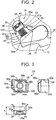
- FIG. 2 is an enlarged view of each ratchet mechanism 16 shown in FIG. 1 .
- Each of the ratchet mechanisms 16 includes the pawl 20 and a spring 22.
- the pawl 20 is provided on the outer plate 14 in a state where the pawl 20 is pivotable.
- the spring 22 is provided between the pawl 20 and the outer plate 14, and pivots the pawl 20 toward the inner plate 12 by pressing the pawl 20 toward the inner plate 12.
- the spring 22 is formed of a coil spring, and is connected to the outer plate 14 via a spring seat 24 that supports the spring 22.
- the outer plate 14 has the pockets 26.
- Each pocket 26 is used to define a space that accommodates the pawl 20, the spring 22 and the spring seat 24.
- the pockets 26 are formed by pressing (punching).
- Each pawl 20 has a predetermined thickness, and is formed so as to be accommodated in a corresponding one of the pockets 26. Each pawl 20 is fitted into the space defined by a corresponding one of the pockets 26 of the outer plate 14. A distal end 20a of each pawl 20 pivots toward one of the notches 21 of the inner plate 12 as indicated by the dashed line in FIG. 2 . Specifically, as shown in FIG. 2 , each pawl 20 is configured to pivot between a state where the distal end 20a is not engaged with any notch 21 as indicated by the continuous line and a state where the distal end 20a is engaged with one of the notches 21 as indicated by the dashed line. The distal end 20a of each pawl 20 is pressed by the corresponding spring 22 toward a side at which the distal end 20a is engaged with one of the notches 21.
- the notches 21 are formed in a sawtooth wave (triangular wave) shape in which a portion having a gentle gradient face that contacts the distal end 20a of the pawl 20 and a portion having a steep gradient face that contacts the distal end 20a of the pawl 20 are alternately formed.
- a sawtooth wave triangular wave
- FIG. 1 when the outer plate 14 rotates in a counterclockwise direction (the other direction), and when the distal ends 20a of the pawls 20 are pressed against the notches 21 of the inner plate 12, the distal ends 20a of the pawls 20 mesh with the notches 21 of the inner plate 12, so relative rotation between the inner plate 12 and the outer plate 14 is stopped, and the outer plate 14 is locked so as to be non-rotatable.
- each pawl 20 When the outer plate 14 rotates at a predetermined rotation speed or higher, the distal end 20a of each pawl 20 is caused to pivot toward the outer plate 14 (radially outward) by centrifugal force against the urging force of the corresponding spring 22 as indicated by the continuous line in FIG. 2 . Therefore, the distal end 20a of each pawl 20 does not mesh with any notch 21, so relative rotation between the inner plate 12 and the outer plate 14 is permitted.
- each spring 22 in the longitudinal direction is crimped to and supported by the spring seat 24, and the other end of the spring 22 in the longitudinal direction is in contact with the corresponding pawl 20.
- Each spring seat 24 is fitted so as to be accommodated in the space defined by a corresponding one of the pockets 26 of the outer plate 14.
- Each spring 22 is small and has a diameter of several millimeters, so the width of the space is also similarly small and is about several millimeters. When the width of such a space defined by pressing is small, it is difficult to form the wall face, connecting the end points of the space, in a planar shape. Specifically, as shown in FIG.
- a bottom wall face 30 of the outer plate 14, facing the planar-shaped planar portion 28 (described later) of each spring seat 24, is formed in a circular arc shape. Therefore, when each spring 22 is directly supported by a corresponding one of the bottom wall faces 30 of the outer plate 14, the central axis of the spring 22 tends to fluctuate. In order to eliminate this situation, in the present embodiment, each spring 22 is supported by the planar-shaped planar portion 28 of the corresponding spring seat 24.
- the planar portion 28 of the spring seat 24, which supports one end of the spring 22, has a planar shape, and it is required to stably seat the planar portion 28 with respect to the outer plate 14.
- the planar portion 28 of each spring seat 24 is in plane contact with the corresponding bottom wall face 30, so the position of each spring seat 24 is stable.
- manufacturing cost significantly increases. Therefore, by forming each spring seat 24 in a shape that will be described later, it is possible to stabilize the position of each spring seat 24 even in a state where each bottom wall face 30 is formed in a circular arc shape.
- FIG. 3 is a view that shows the shape of each spring seat 24 shown in FIG. 2 in detail.
- the spring seat 24 is formed so as to surround the spring 22, and includes the planar portion 28, a pair of spring seat guide portions 32a, 32b (hereinafter, seat guide portions 32a, 32b), spring protection portions 34a, 34b and a pair of crimping portions 38a, 38b.
- One end of the spring 22 in the longitudinal direction is supported by (fixed to) the planar portion 28.
- the pair of seat guide portions 32a, 32b extend perpendicularly from the planar portion 28.
- the spring protection portions 34a, 34b extend perpendicularly from the pair of seat guide portions 32a, 32b so as to protect the spring 22.
- the pair of crimping portions 38a, 38b extend perpendicularly from the planar portion 28.
- the spring seat 24 is formed of a metal plate (thin plate), and is formed by pressing (punching).
- the seat guide portions 32a, 32b correspond to a pair of guide portions.
- a face that receives the spring 22 is formed in a planar shape.
- the planar portion 28 is viewed in a direction perpendicular to the face that receives the spring 22, the planar portion 28 is formed in substantially a rectangular shape.
- the planar portion 28 has a cylindrical portion 40 at its center.
- the cylindrical portion 40 is used to position the spring 22.
- the spring 22 is fitted to the cylindrical portion 40.
- the pair of crimping portions 38a, 38b are formed so as to be bent substantially perpendicularly with respect to the planar portion 28.
- the crimping portions 38a, 38b are opposed to each other across the cylindrical portion 40.
- the crimping portions 38a, 38b are deformed to be crimped in a state where the spring 22 is fitted to the cylindrical portion 40.
- the position of the spring 22 is stable and the fluctuation of the central axis of the spring 22 is reduced as compared to the case where the spring 22 is supported by the circular arc bottom wall face 30.
- the pair of seat guide portions 32a, 32b are formed by being bent perpendicularly from the planar portion 28.
- the seat guide portions 32a, 32b face each other across the spring 22 in a state where the spring 22 is connected to the cylindrical portion 40 (see FIG. 2 ), and extend parallel to the direction in which the spring 22 extends or contracts.
- the spring protection portions 34a, 34b are formed by being further bent substantially perpendicularly from the corresponding seat guide portions 32a, 32b.
- the spring protection portions 34a, 34b each are formed in a rectangular shape, and face each other across the spring 22 in a state where the spring 22 is connected.
- the seat guide portions 32a, 32b and the spring protection portions 34a, 34b are formed so as to surround the spring 22 in all directions. Since the spring protection portions 34a, 34b are formed, even when the spring 22 connected to the planar portion 28 bends, the spring 22 contacts the spring protection portions 34a, 34b, so interference of the spring 22 with a member other than the spring seat 24 is prevented.
- Flange portions 36a, 36b are formed in the seat guide portions 32a, 32b at a position located a predetermined distance L from the planar portion 28 so as to be bent at a predetermined taper angle away from each other with respect to the mutually facing seat guide portions 32b, 32a. Therefore, the flange portions 36a, 36b of the seat guide portions 32a, 32b, located the predetermined distance L from the planar portion 28, are expanded away from the spring 22 in a state where the spring 22 is connected.
- the spring seat 24 is installed such that the planar portion 28 covers the bottom wall face 30 of the outer plate 14 in a state where the spring 22 is connected to the planar portion 28.
- Wall faces 41a, 41b of the outer plate 14, which contact the spring seat 24, are parallel to the direction in which the spring 22 extends or contracts, and respectively have stepped portions at a position located a predetermined distance from the bottom wall face 30.
- the wall face 41 a has a first wall face 42 and a second wall face 44.
- the first wall face 42 contacts a portion of the seat guide portion 32a near the planar portion 28.
- the second wall face 44 contacts an opening-side end of the flange portion 36a of the seat guide portion 32a.
- a stepped portion is provided between the first wall face 42 and the second wall face 44.
- the wall face 41b of the outer plate 14, which contacts the seat guide portion 32b of the corresponding spring seat 24, will be described.
- the wall face 41b has a third wall face 46 and a fourth wall face 48.
- the third wall face 46 contacts a portion of the seat guide portion 32b near the planar portion 28.
- the fourth wall face 48 contacts an opening-side end of the flange portion 36b of the seat guide portion 32b.
- a stepped portion is provided between the third wall face 46 and the fourth wall face 48.
- the length of the clearance between the second wall face 44 and the fourth wall face 48 is larger than the length of the clearance between the first wall face 42 and the third wall face 46.
- each spring seat 24 contact the four portions, that is, the first to fourth wall faces 42, 44, 46, 48 of the outer plate 14, so rattling of each spring seat 24 with respect to the outer plate 14 is reduced, with the result that the position of the planar portion 28 of each spring seat 24 is stable.
- the planar portion 28 has a planar shape, and each spring 22 is supported by the planar portion 28, so the fluctuation of each spring 22 is suppressed, with the result that the position of each spring 22 is also stable.
- each spring seat 24 is not stable when the seat guide portions 32a, 32b of each spring seat 24 respectively contact the first wall face 42 and the third wall face 46 only.
- the flange portions 36a, 36b of the seat guide portions 32a, 32b respectively contact the second wall face 44 and the fourth wall face 48, the position of the spring seat 24 is stable.
- each spring seat 24 when the opening-side ends of the flange portions 36a, 36b of the seat guide portions 32a, 32b, located the predetermined distance L from the planar portion 28, respectively contact the second wall face 44 and the fourth wall face 48, for example, even when force that changes the position of the planar portion 28 acts on the planar portion 28 via the spring 22, reaction force that acts in a direction to keep the position of the planar portion 28 occurs at the contact portion at which the seat guide portion 32a contacts the second wall face 44 or the contact portion at which the seat guide portion 32b contacts the fourth wall face 48, so a change in the position of the planar portion 28 is prevented.
- At least the seat guide portions 32a, 32b of the spring seat 24 are made of a material softer than the spring 22, and the stiffness of the seat guide portions 32a, 32b of the spring seat 24 is lower than the stiffness of the spring 22. In this way, since the stiffness of the seat guide portions 32a, 32b of the spring seat 24 is lower than the stiffness of the spring 22, even if the spring 22 bends and contacts the spring seat 24, abrasion and breakage of the spring 22 are prevented.
- the flange portions 36a, 36b of the seat guide portions 32a, 32b are respectively inclined away from the spring 22, even if the spring 22 bends and contacts the spring seat 24, the flange portions 36a, 36b of the seat guide portions 32a, 32b are prevented from getting caught in between the steel wires of the spring 22.
- each spring seat 24 includes the seat guide portions 32a, 32b that contact the outer plate 14, the fluctuation of the spring seat 24 and the fluctuation of the spring 22 are suppressed by the seat guide portions 32a, 32b, so it is possible to reliably prevent interference of the spring 22 with its peripheral portion. Therefore, a load on each spring 22 is reduced, so it is possible to improve the durability of the one-way clutch 10.
- each spring seat 24 The opening-side ends of the pair of seat guide portions 32a, 32b of each spring seat 24 contact the outer plate 14 in a state where the flange portions 36a, 36b located the predetermined distance L from the planar portion 28 are respectively expanded away from the corresponding spring 22. Therefore, force that suppresses the fluctuation of each spring seat 24 acts between each of the flange portions 36a, 36b of the seat guide portions 32a, 32b and the outer plate 14, so the position of each spring seat 24 is stable. Even when the spring 22 bends, the seat guide portions 32a, 32b are prevented from getting caught in between the steel wires of the spring 22.
- each spring seat 24 since the stiffness of at least the seat guide portions 32a, 32b of each spring seat 24 is lower than the stiffness of the corresponding spring 22, even if the spring 22 bends and contacts the seat guide portions 32a, 32b, abrasion of the spring 22 is reduced.
- FIG. 4 shows the structure of each ratchet mechanism 60 according to another embodiment.
- the ratchet mechanisms 60 are provided between an inner plate 62 and an outer plate 64.
- Each of the ratchet mechanisms 60 includes a pawl 66, a spring 70, and a spring seat 72.
- the pawl 66 is provided in a state where the pawl 66 is pivotable toward the inner plate 62.
- the spring 70 is provided between the pawl 66 and the outer plate 64.
- the spring 70 pivots the pawl 66 toward the inner plate 62 by pressing the pawl 66 toward the inner plate 62.
- the spring seat 72 is connected to the outer plate 64, and supports the spring 70.
- the spring 70 and the spring seat 72 are shown in cross-sectional view.
- the inner plate 62 corresponds to the first member or the other member.
- the outer plate 64 corresponds to the second member or one member.
- the outer plate 64 has pockets 74.
- Each pocket 74 is used to define a space that accommodates the pawl 66, the spring 70 and the spring seat 72.
- the pockets 74 are formed by pressing (punching).
- Each ratchet mechanism 60 according to the present embodiment differs from each ratchet mechanism 16 according to the above-described embodiment in the shape of the spring seat 72 and the shape of the pocket 74 of the outer plate 64.
- the structures of the outer plate 64 and each spring seat 72, different from those of the above-described embodiment, will be described.
- Each spring seat 72 is fitted to a wall face (clearance) defined by a corresponding one of the pockets 74 of the outer plate 64.
- Each spring seat 72 includes a planar portion 76 and a pair of spring seat guide portions 78a, 78b.
- the planar portion 76 supports one end of the spring 70.
- the pair of spring seat guide portions 78a, 78b extend perpendicularly from the planar portion 76.
- crimping portions and spring protection portions are provided.
- each spring seat 72 is formed of a metal plate, and is formed by pressing (punching).
- the spring seat guide portions 78a, 78b correspond to the pair of guide portions according to the present invention.
- planar portion 76 a face that supports the spring 70 is formed in a planar shape.
- planar portion 76 is viewed in a direction perpendicular to the face that supports the spring 70, the planar portion 76 is formed in substantially a rectangular shape.
- the planar portion 76 has a cylindrical portion 80 at its center. The cylindrical portion 80 is used to position the spring 70.
- the pair of spring seat guide portions 78a, 78b (hereinafter, the seat guide portions 78a, 78b) are formed by being bent perpendicularly from the planar portion 76.
- the seat guide portions 78a, 78b face each other across the spring 70 and extend parallel to the direction in which the spring 70 extends or contracts in a state where the spring 70 is connected to the spring seat 72.
- Flange portions 82a, 82b are formed in the seat guide portions 78a, 78b at a position located a predetermined distance from the planar portion 76 so as to be bent perpendicularly away from the spring 70.
- each pocket 74 defines a first wall face 84 and a second wall face 86 that are parallel to the direction in which the spring 70 extends or contracts and that respectively contact the spring seat guide portions 78a, 78b.
- each pocket 74 defines a third wall face 88 and a fourth wall face 90 that are parallel to the flange portions 82a, 82b and that respectively contact the flange portions 82a, 82b.
- each spring seat 72 contacts the four portions, that is, the first to fourth wall faces 84, 86, 88, 90, so rattling of each spring seat 72 with respect to the outer plate 64 is reduced, with the result that the position of the planar portion 76 of each spring seat 72 is stable.
- the position of the spring seat 72 is not stable when the seat guide portions 78a, 78b of each spring seat 72 respectively contact the first wall face 84 and the second wall face 86 only.
- the flange portions 82a, 82b provided in the seat guide portions 78a, 78b respectively contact the third wall face 88 and the fourth wall face 90, so the position of each spring seat 72 is stable.
- each spring seat 72 When the flange portions 82a, 82b of each spring seat 72 contact the third wall face 88 and the fourth wall face 90, even when force that changes the position of the planar portion 78 acts on the planar portion 78, reaction force that acts in a direction to keep the position of the corresponding spring seat 72 occurs at the contact portion at which the flange portion 82a contacts the third wall face 88 or the contact portion at which the flange portion 82b contacts the fourth wall face 90, so a change in the position of each spring seat 72 is prevented.
- At least the seat guide portions 78a, 78b of the spring seat 72 are made of a material softer than the spring 70, and the stiffness of the seat guide portions 78a, 78b of the spring seat 72 is lower than the stiffness of the spring 70. In this way, since the stiffness of the seat guide portions 78a, 78b of the spring seat 72 is lower than the stiffness of the spring 70, even if the spring 70 bends and contacts the seat guide portions 78a, 78b of the spring seat 72, abrasion and breakage of the spring 70 are prevented.
- the flange portions 82a, 82b of the seat guide portions 78a, 78b are respectively inclined away from the spring 70, even if the spring 70 bends and contacts the spring seat 72, the seat guide portions 78a, 78b are prevented from getting caught in between the steel wires of the spring 70.
- each spring seat 72 without forming the wall face of the space, in which the spring seat 72 of the outer plate 64 is accommodated, in a planar shape. Therefore, the fluctuation of each spring 70 that is supported by the corresponding spring seat 72 is suppressed, so interference of each spring 70 with its peripheral portion is reliably prevented, with the result that it is possible to improve the durability of the one-way clutch.
- each spring seat 24 is provided on the outer plate 14 or each spring seat 72 is provided on the outer plate 64.
- each spring seat 24 may be provided on the inner plate 12, and the pawl 20 may be pressed toward the outer plate 14 by the spring 22, or each spring seat 72 may be provided on the inner plate 62, and the pawl 66 may be pressed toward the outer plate 64 by the spring 70.
- the outer plate 14 rotates, and the rotation of the inner plate 12 is stopped. Instead, the rotation of the outer plate 14 may be stopped, and the inner plate 12 may rotate.
- each spring seat 24 or each spring seat 72 has the spring protection portions 34a, 34b. Instead, the spring protection portions 34a, 34b are not necessarily required. Each spring seat 24 or each spring seat 72 does not need to have the spring protection portion 34a, 34b.
Landscapes
- Engineering & Computer Science (AREA)
- General Engineering & Computer Science (AREA)
- Mechanical Engineering (AREA)
- Springs (AREA)
- Braking Arrangements (AREA)
- Mechanical Operated Clutches (AREA)
Abstract
Description
- The present invention relates to the structure of a one-way clutch and, more particularly, to improvement in the durability of a one-way clutch.
- There is well known a one-way clutch including an inner plate, an outer plate and ratchet mechanisms. The ratchet mechanisms permit relative rotation of these inner plate and outer plate in one direction, and stop relative rotation in the other direction. In a one-way clutch described in International Application Publication No.
1999/45289 - In the thus configured one-way clutch, when the outer plate rotates at a low rotation speed, the elastic force of each spring overcomes centrifugal force caused by rotation, and each pawl is pressed against the inner plate. At this time, when the outer plate relatively rotates in one direction with respect to the inner plate, the rotation is permitted; however, when the outer plate relatively rotates in the other direction with respect to the inner plate, the pawls mesh with the notches of the inner plate, with the result that the outer plate and the inner plate are locked so as to be relatively non-rotatable.
- In the one-way clutch described in International Application Publication No.
1999/45289 - The present invention provides the structure of a one-way clutch that includes a ratchet mechanism and that improves the durability of the one-way clutch.
- An example aspect of the present invention provides a one-way clutch. The one-way clutch includes a first member, a second member and a ratchet mechanism. The first member is arranged around a rotation axis. The second member is arranged around the rotation axis so as to surround the first member. The ratchet mechanism is provided between the first member and the second member, the ratchet mechanism is configured to permit relative rotation between the first member and the second member in one direction. The ratchet mechanism is configured to stop relative rotation between the first member and the second member in the other direction. The ratchet mechanism includes a pawl, and a spring seat. The pawl is provided on one of the first member and the second member. The pawl is configured to pivot toward the other of the first member and the second member. The spring is provided between the pawl and the one of the first member and the second member. The spring is configured to press the pawl toward the other of the first member and the second member such that the pawl pivots toward the other of the first member and the second member, and a spring seat supports the spring. The spring is connected to the one of the first member and the second member via the spring seat the spring seat includes a planar portion and a pair of guide portions. The planar portion has a planar shape for receiving one end of the spring. The pair of guide portions extends from the planar portion parallel in a direction in which the spring extends or contracts.
- With the above configuration, since one end of the spring is received by the planar portion of the spring seat, it is possible to support the spring with a planar member without machining the one of the first member and the second member into a planar shape. Since the spring seat has the guide portions that contact the one of the first member and the second member, it is possible to suppress the fluctuation of the spring seat and the fluctuation of the spring by the guide portions, so it is possible to reliably prevent interference of the spring with its peripheral portion. Therefore, a load on the spring is reduced, so it is possible to improve the durability of the one-way clutch.
- The one-way clutch may further be provided that the pair of guide portions of the spring seat may expand away from the spring at a position located a predetermined distance from the planar portion. At least part of portions of the pair of guide portions, is located the predetermined distance from the planar portion, are in contact with the one of the first member and the second member.
- With the above configuration, the pair of guide portions of the spring seat expand away from the spring at a position located the predetermined distance from the planar portion, and at least part of the guide portions are in contact with the one of the first member and the second member, so force that suppresses the fluctuation of the spring seat acts on the spring seat between each of the portions of the guide portions, located the predetermined distance from the planar portion, and the one of the first member and the second member, with the result that the position of the spring seat is stable. Even when the spring bends, the guide portions are prevented from getting caught in between the steel wires of the spring.
- The one-way clutch may further be provided that the stiffness of the guide portions is lower than the stiffness of the spring.
- With the above configuration, since the stiffness of at least the guide portions of the spring seat is lower than the stiffness of the spring, even if the spring bends and contacts the guide portions, it is possible to reduce abrasion of the spring.
- Features, advantages, and technical and industrial significance of exemplary embodiments of the present invention will be described below with reference to the accompanying drawings, in which like numerals denote like elements, and wherein:
-
FIG. 1 is a view that shows the overall structure of a one-way clutch according to an embodiment of the present invention; -
FIG. 2 is an enlarged view of each ratchet mechanism shown inFIG. 1 ; -
FIG. 3 is a view that illustrates the shape of a spring seat shown inFIG. 2 ; and -
FIG. 4 is a view that shows the structure of each ratchet mechanism according to another embodiment of the present invention. - Hereinafter, embodiments of the present invention will be described in detail with reference to the accompanying drawings. In the following embodiments, the drawings are simplified or modified as needed, and the scale ratio, shape and the like, of each portion are not always accurately drawn.
-
FIG. 1 shows the overall structure of a one-way clutch 10 according to an embodiment of the present invention. The one-way clutch 10 is, for example, provided on a crankshaft of an engine (not shown), and is used to, for example, prevent reverse rotation of the crankshaft. - The one-
way clutch 10 includes aninner plate 12, anouter plate 14, and a plurality ofratchet mechanisms 16. The plurality ofratchet mechanisms 16 are arranged in the circumferential direction between theinner plate 12 and theouter plate 14. Theinner plate 12 corresponds to a first member or the other member according to the present invention. Theouter plate 14 corresponds to a second member or one member according to the present invention. - The
inner plate 12 is formed in a disc shape by pressing a flat plate having a predetermined thickness. Theinner plate 12 is arranged around a rotation axis C. Rotation of theinner plate 12 is constantly stopped by spline-fitting the inner peripheral portion of theinner plate 12 to anon-rotating member 18.Notches 21 are periodically provided on the outer periphery of theinner plate 12. Thenotches 21 are engageable with pawls 20 (described later) of theratchet mechanisms 16. - The
outer plate 14 is formed in a disc shape by pressing a flat plate having a predetermined thickness. Theouter plate 14 has a circular space at its inner peripheral side. Theouter plate 14 is arranged on the outer peripheral side of theinner plate 12 around the rotation axis C so as to surround theinner plate 12. - The
ratchet mechanisms 16 are provided between theinner plate 12 and theouter plate 14. Theratchet mechanisms 16 permit relative rotation between theinner plate 12 and theouter plate 14 in one direction, and stop relative rotation between theinner plate 12 and theouter plate 14 in the other direction.FIG. 2 is an enlarged view of eachratchet mechanism 16 shown inFIG. 1 . - Each of the
ratchet mechanisms 16 includes thepawl 20 and aspring 22. Thepawl 20 is provided on theouter plate 14 in a state where thepawl 20 is pivotable. Thespring 22 is provided between thepawl 20 and theouter plate 14, and pivots thepawl 20 toward theinner plate 12 by pressing thepawl 20 toward theinner plate 12. Thespring 22 is formed of a coil spring, and is connected to theouter plate 14 via aspring seat 24 that supports thespring 22. - The
outer plate 14 has thepockets 26. Eachpocket 26 is used to define a space that accommodates thepawl 20, thespring 22 and thespring seat 24. Thepockets 26 are formed by pressing (punching). - Each
pawl 20 has a predetermined thickness, and is formed so as to be accommodated in a corresponding one of thepockets 26. Eachpawl 20 is fitted into the space defined by a corresponding one of thepockets 26 of theouter plate 14. Adistal end 20a of eachpawl 20 pivots toward one of thenotches 21 of theinner plate 12 as indicated by the dashed line inFIG. 2 . Specifically, as shown inFIG. 2 , eachpawl 20 is configured to pivot between a state where thedistal end 20a is not engaged with anynotch 21 as indicated by the continuous line and a state where thedistal end 20a is engaged with one of thenotches 21 as indicated by the dashed line. Thedistal end 20a of eachpawl 20 is pressed by the correspondingspring 22 toward a side at which thedistal end 20a is engaged with one of thenotches 21. - The
notches 21 are formed in a sawtooth wave (triangular wave) shape in which a portion having a gentle gradient face that contacts thedistal end 20a of thepawl 20 and a portion having a steep gradient face that contacts thedistal end 20a of thepawl 20 are alternately formed. Thus, inFIG. 1 , when theouter plate 14 rotates in a clockwise direction (one direction), the distal ends 20a of thepawls 20 relatively move along the wall faces of thenotches 21 even when the distal ends 20a of thepawls 20 are pressed against thenotches 21 of theinner plate 12. Therefore, the distal ends 20a of thepawls 20 do not mesh with thenotches 21, so relative rotation between theinner plate 12 and theouter plate 14 is permitted. - On the other hand, in
FIG. 1 , when theouter plate 14 rotates in a counterclockwise direction (the other direction), and when the distal ends 20a of thepawls 20 are pressed against thenotches 21 of theinner plate 12, the distal ends 20a of thepawls 20 mesh with thenotches 21 of theinner plate 12, so relative rotation between theinner plate 12 and theouter plate 14 is stopped, and theouter plate 14 is locked so as to be non-rotatable. - When the
outer plate 14 rotates at a predetermined rotation speed or higher, thedistal end 20a of eachpawl 20 is caused to pivot toward the outer plate 14 (radially outward) by centrifugal force against the urging force of thecorresponding spring 22 as indicated by the continuous line inFIG. 2 . Therefore, thedistal end 20a of eachpawl 20 does not mesh with anynotch 21, so relative rotation between theinner plate 12 and theouter plate 14 is permitted. - One end of each
spring 22 in the longitudinal direction is crimped to and supported by thespring seat 24, and the other end of thespring 22 in the longitudinal direction is in contact with the correspondingpawl 20. Eachspring seat 24 is fitted so as to be accommodated in the space defined by a corresponding one of thepockets 26 of theouter plate 14. Eachspring 22 is small and has a diameter of several millimeters, so the width of the space is also similarly small and is about several millimeters. When the width of such a space defined by pressing is small, it is difficult to form the wall face, connecting the end points of the space, in a planar shape. Specifically, as shown inFIG. 2 , a bottom wall face 30 of theouter plate 14, facing the planar-shaped planar portion 28 (described later) of eachspring seat 24, is formed in a circular arc shape. Therefore, when eachspring 22 is directly supported by a corresponding one of the bottom wall faces 30 of theouter plate 14, the central axis of thespring 22 tends to fluctuate. In order to eliminate this situation, in the present embodiment, eachspring 22 is supported by the planar-shapedplanar portion 28 of thecorresponding spring seat 24. - Incidentally, the
planar portion 28 of thespring seat 24, which supports one end of thespring 22, has a planar shape, and it is required to stably seat theplanar portion 28 with respect to theouter plate 14. For example, if a method of machining eachpocket 26 is changed and eachbottom wall face 30 is formed in a planar shape, theplanar portion 28 of eachspring seat 24 is in plane contact with the correspondingbottom wall face 30, so the position of eachspring seat 24 is stable. However, if eachbottom wall face 30 is formed in a planar shape, manufacturing cost significantly increases. Therefore, by forming eachspring seat 24 in a shape that will be described later, it is possible to stabilize the position of eachspring seat 24 even in a state where eachbottom wall face 30 is formed in a circular arc shape. -
FIG. 3 is a view that shows the shape of eachspring seat 24 shown inFIG. 2 in detail. Thespring seat 24 is formed so as to surround thespring 22, and includes theplanar portion 28, a pair of springseat guide portions seat guide portions spring protection portions portions spring 22 in the longitudinal direction is supported by (fixed to) theplanar portion 28. The pair ofseat guide portions planar portion 28. Thespring protection portions seat guide portions spring 22. The pair of crimpingportions planar portion 28. Thespring seat 24 is formed of a metal plate (thin plate), and is formed by pressing (punching). Theseat guide portions - In the
planar portion 28, a face that receives thespring 22 is formed in a planar shape. When theplanar portion 28 is viewed in a direction perpendicular to the face that receives thespring 22, theplanar portion 28 is formed in substantially a rectangular shape. Theplanar portion 28 has acylindrical portion 40 at its center. Thecylindrical portion 40 is used to position thespring 22. Thespring 22 is fitted to thecylindrical portion 40. The pair of crimpingportions planar portion 28. The crimpingportions cylindrical portion 40. In fixing thespring 22 to thespring seat 24, the crimpingportions spring 22 is fitted to thecylindrical portion 40. In this way, when thespring 22 is supported by theplanar portion 28 having a planar shape, the position of thespring 22 is stable and the fluctuation of the central axis of thespring 22 is reduced as compared to the case where thespring 22 is supported by the circular arcbottom wall face 30. - The pair of
seat guide portions planar portion 28. Theseat guide portions spring 22 in a state where thespring 22 is connected to the cylindrical portion 40 (seeFIG. 2 ), and extend parallel to the direction in which thespring 22 extends or contracts. Thespring protection portions seat guide portions spring protection portions spring 22 in a state where thespring 22 is connected. Thus, in a state where thespring 22 is connected, theseat guide portions spring protection portions spring 22 in all directions. Since thespring protection portions spring 22 connected to theplanar portion 28 bends, thespring 22 contacts thespring protection portions spring 22 with a member other than thespring seat 24 is prevented. -
Flange portions seat guide portions planar portion 28 so as to be bent at a predetermined taper angle away from each other with respect to the mutually facingseat guide portions flange portions seat guide portions planar portion 28, are expanded away from thespring 22 in a state where thespring 22 is connected. - As shown in
FIG. 2 , thespring seat 24 is installed such that theplanar portion 28 covers the bottom wall face 30 of theouter plate 14 in a state where thespring 22 is connected to theplanar portion 28. Wall faces 41a, 41b of theouter plate 14, which contact thespring seat 24, are parallel to the direction in which thespring 22 extends or contracts, and respectively have stepped portions at a position located a predetermined distance from thebottom wall face 30. - Each
wall face 41a of theouter plate 14, which contacts theseat guide portion 32a of thecorresponding spring seat 24, will be described. The wall face 41 a has a first wall face 42 and asecond wall face 44. The first wall face 42 contacts a portion of theseat guide portion 32a near theplanar portion 28. The second wall face 44 contacts an opening-side end of theflange portion 36a of theseat guide portion 32a. A stepped portion is provided between the first wall face 42 and thesecond wall face 44. - Each
wall face 41b of theouter plate 14, which contacts theseat guide portion 32b of thecorresponding spring seat 24, will be described. Thewall face 41b has athird wall face 46 and afourth wall face 48. The third wall face 46 contacts a portion of theseat guide portion 32b near theplanar portion 28. The fourth wall face 48 contacts an opening-side end of theflange portion 36b of theseat guide portion 32b. A stepped portion is provided between thethird wall face 46 and thefourth wall face 48. - Since the stepped portions are provided, the length of the clearance between the
second wall face 44 and thefourth wall face 48 is larger than the length of the clearance between the first wall face 42 and thethird wall face 46. When thespring seat 24 is fitted to theouter plate 14, the portion of theseat guide portion 32a near theplanar portion 28 contacts the first wall face 42, and the opening-side end of theflange portion 36a of theseat guide portion 32a contacts thesecond wall face 44. The portion of theseat guide portion 32b near theplanar portion 28 contacts thethird wall face 46, and the opening-side end of theflange portion 36b of theseat guide portion 32b contacts thefourth wall face 48. - In this way, the
seat guide portions spring seat 24 contact the four portions, that is, the first to fourth wall faces 42, 44, 46, 48 of theouter plate 14, so rattling of eachspring seat 24 with respect to theouter plate 14 is reduced, with the result that the position of theplanar portion 28 of eachspring seat 24 is stable. In addition, theplanar portion 28 has a planar shape, and eachspring 22 is supported by theplanar portion 28, so the fluctuation of eachspring 22 is suppressed, with the result that the position of eachspring 22 is also stable. - For example, it is also presumable that the position of each
spring seat 24 is not stable when theseat guide portions spring seat 24 respectively contact the first wall face 42 and thethird wall face 46 only. In contrast, since theflange portions seat guide portions second wall face 44 and thefourth wall face 48, the position of thespring seat 24 is stable. In eachspring seat 24, when the opening-side ends of theflange portions seat guide portions planar portion 28, respectively contact thesecond wall face 44 and thefourth wall face 48, for example, even when force that changes the position of theplanar portion 28 acts on theplanar portion 28 via thespring 22, reaction force that acts in a direction to keep the position of theplanar portion 28 occurs at the contact portion at which theseat guide portion 32a contacts thesecond wall face 44 or the contact portion at which theseat guide portion 32b contacts thefourth wall face 48, so a change in the position of theplanar portion 28 is prevented. - At least the
seat guide portions spring seat 24 are made of a material softer than thespring 22, and the stiffness of theseat guide portions spring seat 24 is lower than the stiffness of thespring 22. In this way, since the stiffness of theseat guide portions spring seat 24 is lower than the stiffness of thespring 22, even if thespring 22 bends and contacts thespring seat 24, abrasion and breakage of thespring 22 are prevented. - Since the
flange portions seat guide portions spring 22, even if thespring 22 bends and contacts thespring seat 24, theflange portions seat guide portions spring 22. - As described above, since one end of each
spring 22 is received by theplanar portion 28 of thecorresponding spring seat 24, it is possible to support eachspring 22 with a planar member without machining a corresponding one of the bottom wall faces 30 of theouter plate 14 into a planar shape. Since eachspring seat 24 includes theseat guide portions outer plate 14, the fluctuation of thespring seat 24 and the fluctuation of thespring 22 are suppressed by theseat guide portions spring 22 with its peripheral portion. Therefore, a load on eachspring 22 is reduced, so it is possible to improve the durability of the one-way clutch 10. - The opening-side ends of the pair of
seat guide portions spring seat 24 contact theouter plate 14 in a state where theflange portions planar portion 28 are respectively expanded away from the correspondingspring 22. Therefore, force that suppresses the fluctuation of eachspring seat 24 acts between each of theflange portions seat guide portions outer plate 14, so the position of eachspring seat 24 is stable. Even when thespring 22 bends, theseat guide portions spring 22. - In addition, since the stiffness of at least the
seat guide portions spring seat 24 is lower than the stiffness of thecorresponding spring 22, even if thespring 22 bends and contacts theseat guide portions spring 22 is reduced. - Next, another embodiment will be described. In the following description, like reference numerals denote the same portions as those of the above-described embodiment, and the description thereof is omitted.
-
FIG. 4 shows the structure of eachratchet mechanism 60 according to another embodiment. Theratchet mechanisms 60 are provided between aninner plate 62 and anouter plate 64. Each of theratchet mechanisms 60 includes apawl 66, aspring 70, and aspring seat 72. Thepawl 66 is provided in a state where thepawl 66 is pivotable toward theinner plate 62. Thespring 70 is provided between thepawl 66 and theouter plate 64. Thespring 70 pivots thepawl 66 toward theinner plate 62 by pressing thepawl 66 toward theinner plate 62. Thespring seat 72 is connected to theouter plate 64, and supports thespring 70. InFIG. 4 , thespring 70 and thespring seat 72 are shown in cross-sectional view. Theinner plate 62 corresponds to the first member or the other member. Theouter plate 64 corresponds to the second member or one member. - The
outer plate 64 haspockets 74. Eachpocket 74 is used to define a space that accommodates thepawl 66, thespring 70 and thespring seat 72. Thepockets 74 are formed by pressing (punching). - Each
ratchet mechanism 60 according to the present embodiment differs from eachratchet mechanism 16 according to the above-described embodiment in the shape of thespring seat 72 and the shape of thepocket 74 of theouter plate 64. Hereinafter, the structures of theouter plate 64 and eachspring seat 72, different from those of the above-described embodiment, will be described. - Each
spring seat 72 is fitted to a wall face (clearance) defined by a corresponding one of thepockets 74 of theouter plate 64. Eachspring seat 72 includes aplanar portion 76 and a pair of springseat guide portions planar portion 76 supports one end of thespring 70. The pair of springseat guide portions planar portion 76. Although not shown inFIG. 4 , as in the case of the above-described embodiment, crimping portions and spring protection portions are provided. In the present embodiment as well, eachspring seat 72 is formed of a metal plate, and is formed by pressing (punching). The springseat guide portions - In the
planar portion 76, a face that supports thespring 70 is formed in a planar shape. When theplanar portion 76 is viewed in a direction perpendicular to the face that supports thespring 70, theplanar portion 76 is formed in substantially a rectangular shape. Theplanar portion 76 has acylindrical portion 80 at its center. Thecylindrical portion 80 is used to position thespring 70. - The pair of spring
seat guide portions seat guide portions planar portion 76. Theseat guide portions spring 70 and extend parallel to the direction in which thespring 70 extends or contracts in a state where thespring 70 is connected to thespring seat 72. -
Flange portions seat guide portions planar portion 76 so as to be bent perpendicularly away from thespring 70. - In the
outer plate 64, eachpocket 74 defines afirst wall face 84 and asecond wall face 86 that are parallel to the direction in which thespring 70 extends or contracts and that respectively contact the springseat guide portions outer plate 64, eachpocket 74 defines athird wall face 88 and afourth wall face 90 that are parallel to theflange portions flange portions - In this way, each
spring seat 72 contacts the four portions, that is, the first to fourth wall faces 84, 86, 88, 90, so rattling of eachspring seat 72 with respect to theouter plate 64 is reduced, with the result that the position of theplanar portion 76 of eachspring seat 72 is stable. - For example, it is also presumable that the position of the
spring seat 72 is not stable when theseat guide portions spring seat 72 respectively contact thefirst wall face 84 and thesecond wall face 86 only. In contrast, theflange portions seat guide portions third wall face 88 and thefourth wall face 90, so the position of eachspring seat 72 is stable. When theflange portions spring seat 72 contact thethird wall face 88 and thefourth wall face 90, even when force that changes the position of the planar portion 78 acts on the planar portion 78, reaction force that acts in a direction to keep the position of thecorresponding spring seat 72 occurs at the contact portion at which theflange portion 82a contacts thethird wall face 88 or the contact portion at which theflange portion 82b contacts thefourth wall face 90, so a change in the position of eachspring seat 72 is prevented. - In the present embodiment as well, at least the
seat guide portions spring seat 72 are made of a material softer than thespring 70, and the stiffness of theseat guide portions spring seat 72 is lower than the stiffness of thespring 70. In this way, since the stiffness of theseat guide portions spring seat 72 is lower than the stiffness of thespring 70, even if thespring 70 bends and contacts theseat guide portions spring seat 72, abrasion and breakage of thespring 70 are prevented. - Since the
flange portions seat guide portions spring 70, even if thespring 70 bends and contacts thespring seat 72, theseat guide portions spring 70. - With the above-described configuration, it is possible to stabilize the position of each
spring seat 72 without forming the wall face of the space, in which thespring seat 72 of theouter plate 64 is accommodated, in a planar shape. Therefore, the fluctuation of eachspring 70 that is supported by thecorresponding spring seat 72 is suppressed, so interference of eachspring 70 with its peripheral portion is reliably prevented, with the result that it is possible to improve the durability of the one-way clutch. - The embodiments of the present invention are described in detail with reference to the accompanying drawings; however, the present invention is also applied to other embodiments.
- For example, in the above-described embodiments, each
spring seat 24 is provided on theouter plate 14 or eachspring seat 72 is provided on theouter plate 64. Instead, eachspring seat 24 may be provided on theinner plate 12, and thepawl 20 may be pressed toward theouter plate 14 by thespring 22, or eachspring seat 72 may be provided on theinner plate 62, and thepawl 66 may be pressed toward theouter plate 64 by thespring 70. - In the above-described embodiment, the
outer plate 14 rotates, and the rotation of theinner plate 12 is stopped. Instead, the rotation of theouter plate 14 may be stopped, and theinner plate 12 may rotate. - In the above-described embodiments, each
spring seat 24 or eachspring seat 72 has thespring protection portions spring protection portions spring seat 24 or eachspring seat 72 does not need to have thespring protection portion - The above-described embodiments are only illustrative. The present invention may be implemented in modes including various modifications or improvements on the basis of the knowledge of persons skilled in the art.
Claims (3)
- A one-way clutch (10) comprising:a first member (12) arranged around a rotation axis (C),a second member (14) arranged around the rotation axis (C) so as to surround the first member (12), anda ratchet mechanism (16) provided between the first member (12) and the second member (14), the ratchet mechanism (16) being configured to permit relative rotation between the first member (12) and the second member (14) in one direction, and the ratchet mechanism (16) being configured to stop relative rotation between the first member (12) and the second member (14) in the other direction,the ratchet mechanism (16) includinga pawl (20) provided on one of the first member (12) and the second member (14), the pawl (20) being configured to pivot toward the other of the first member (12) and the second member (14),a spring (22) provided between the pawl (20) and the one of the first member (12) and the second member (14), the spring (22) being configured to press the pawl (20) toward the other of the first member (12) and the second member (14) such that the pawl (20) pivots toward the other of the first member (12) and the second member (14), anda spring seat (24) that supports the spring (22), the spring (22) being connected to the one of the first member (12) and the second member (14) via the spring seat (24),the spring seat (24) includinga planar portion (28) having a planar shape for receiving one end of the spring (22), anda pair of guide portions (32a, 32b) extending from the planar portion (28) parallel in a direction in which the spring (22) extends or contracts.
- The one-way clutch according to claim 1, wherein
the pair of guide portions (32a, 32b) of the spring seat (24) expand away from the spring (22) at a position located a predetermined distance from the planar portion (28), and
at least part of portions of the pair of guide portions (32a, 32b), located the predetermined distance from the planar portion (28), are in contact with the one of the first member (12) and the second member (14). - The one-way clutch according to claim 1 or 2, wherein
a stiffness of the guide portions (32a, 32b) is lower than a stiffness of the spring (22).
Applications Claiming Priority (1)
| Application Number | Priority Date | Filing Date | Title |
|---|---|---|---|
| JP2015236123A JP6404807B2 (en) | 2015-12-02 | 2015-12-02 | One way clutch |
Publications (2)
| Publication Number | Publication Date |
|---|---|
| EP3176457A1 true EP3176457A1 (en) | 2017-06-07 |
| EP3176457B1 EP3176457B1 (en) | 2018-08-01 |
Family
ID=57517707
Family Applications (1)
| Application Number | Title | Priority Date | Filing Date |
|---|---|---|---|
| EP16202021.8A Not-in-force EP3176457B1 (en) | 2015-12-02 | 2016-12-02 | One-way clutch |
Country Status (5)
| Country | Link |
|---|---|
| US (1) | US10487888B2 (en) |
| EP (1) | EP3176457B1 (en) |
| JP (1) | JP6404807B2 (en) |
| KR (1) | KR101893474B1 (en) |
| CN (1) | CN107013607B (en) |
Cited By (1)
| Publication number | Priority date | Publication date | Assignee | Title |
|---|---|---|---|---|
| FR3115578A1 (en) * | 2020-10-23 | 2022-04-29 | Valeo Embrayages | One-way clutch device |
Families Citing this family (6)
| Publication number | Priority date | Publication date | Assignee | Title |
|---|---|---|---|---|
| US11035423B2 (en) | 2017-02-02 | 2021-06-15 | Means Industries, Inc. | Non-friction coupling and control assembly, engageable coupling assembly and locking member for use in the assemblies |
| CN110637408B (en) | 2017-05-23 | 2022-11-15 | 三键有限公司 | Laminated steel sheet, method for producing same, engine, and adhesive composition for laminated steel sheet |
| JP6743800B2 (en) * | 2017-10-25 | 2020-08-19 | 株式会社アドヴィックス | Negative pressure type booster |
| JP6844551B2 (en) * | 2018-01-09 | 2021-03-17 | トヨタ自動車株式会社 | Engagement device |
| CN113412205B (en) * | 2019-02-08 | 2024-08-20 | 敏思工业公司 | Non-friction coupling and control assembly, engageable coupling assembly and locking member for use in the assembly |
| FR3131355A1 (en) | 2021-12-28 | 2023-06-30 | Valeo Embrayages | Clutch for a mobility device |
Citations (3)
| Publication number | Priority date | Publication date | Assignee | Title |
|---|---|---|---|---|
| US20020153217A1 (en) * | 2001-04-18 | 2002-10-24 | Yutaka Giken Co., Ltd. | One-way clutch |
| CN103511505A (en) * | 2012-06-25 | 2014-01-15 | 陈伯恒 | Centrifugal clutch |
| DE102015205757A1 (en) * | 2014-04-03 | 2015-10-22 | Nsk-Warner K.K. | One-way clutch of the ratchet wheel type |
Family Cites Families (18)
| Publication number | Priority date | Publication date | Assignee | Title |
|---|---|---|---|---|
| US1883966A (en) * | 1930-09-20 | 1932-10-25 | Frank R Krause | Overrunning clutch |
| US2134405A (en) * | 1937-10-07 | 1938-10-25 | Ingersoll Rand Co | Controlling device |
| US4842109A (en) * | 1987-12-22 | 1989-06-27 | Sundstand Corp. | Bidirectional drive with a unidirectional irreversibility mechanism |
| EP1066477B1 (en) | 1998-03-02 | 2004-10-13 | BorgWarner Inc. | Ratchet one-way clutch assembly |
| US6557681B2 (en) * | 2000-01-26 | 2003-05-06 | Nsk-Warner K.K. | Ratchet type one-way clutch and method of manufacturing the same |
| KR100446394B1 (en) * | 2001-10-30 | 2004-09-01 | 발레오전장시스템스코리아 주식회사 | Over running clutch of start motor |
| US7500548B2 (en) * | 2004-07-27 | 2009-03-10 | Ford Global Technologies, Llc | Dual-mode one-way torque transmitting device |
| US7448481B2 (en) * | 2004-07-27 | 2008-11-11 | Ford Global Technologies, Llc | Ratcheting one-way clutch having rockers actuated by centrifugal force |
| US7455156B2 (en) | 2004-07-27 | 2008-11-25 | Ford Global Technologies, Llc | Overrunning clutch |
| JP4750091B2 (en) * | 2007-10-05 | 2011-08-17 | Nskワーナー株式会社 | Ratchet one-way clutch and stator device using ratchet one-way clutch |
| EP2255711A1 (en) * | 2009-03-17 | 2010-12-01 | Koninklijke Philips Electronics N.V. | Vacuum cleaner |
| CN101832346A (en) * | 2009-06-19 | 2010-09-15 | 肯友股份有限公司 | Improved flywheel structure |
| CN201561076U (en) * | 2009-11-12 | 2010-08-25 | 杭州宗兴齿轮有限公司 | Novel spring reset overrunning clutch |
| JP5485659B2 (en) * | 2009-11-13 | 2014-05-07 | 株式会社テイエルブイ | Check valve |
| JP5461228B2 (en) * | 2010-02-24 | 2014-04-02 | 本田技研工業株式会社 | Spring guide and cushion unit |
| CN203453338U (en) * | 2013-08-01 | 2014-02-26 | 重庆耐迪机电有限公司 | Combined spring cavity overrunning clutch |
| CN203453336U (en) * | 2013-08-12 | 2014-02-26 | 重庆耐迪机电有限公司 | One-way overrunning clutch |
| US9732809B2 (en) * | 2015-05-28 | 2017-08-15 | Ford Global Technologies, Llc | Electro-magnetic and centrifugal clutch |
-
2015
- 2015-12-02 JP JP2015236123A patent/JP6404807B2/en not_active Expired - Fee Related
-
2016
- 2016-11-29 US US15/363,497 patent/US10487888B2/en not_active Expired - Fee Related
- 2016-11-30 CN CN201611081049.XA patent/CN107013607B/en active Active
- 2016-11-30 KR KR1020160162193A patent/KR101893474B1/en not_active Expired - Fee Related
- 2016-12-02 EP EP16202021.8A patent/EP3176457B1/en not_active Not-in-force
Patent Citations (3)
| Publication number | Priority date | Publication date | Assignee | Title |
|---|---|---|---|---|
| US20020153217A1 (en) * | 2001-04-18 | 2002-10-24 | Yutaka Giken Co., Ltd. | One-way clutch |
| CN103511505A (en) * | 2012-06-25 | 2014-01-15 | 陈伯恒 | Centrifugal clutch |
| DE102015205757A1 (en) * | 2014-04-03 | 2015-10-22 | Nsk-Warner K.K. | One-way clutch of the ratchet wheel type |
Cited By (1)
| Publication number | Priority date | Publication date | Assignee | Title |
|---|---|---|---|---|
| FR3115578A1 (en) * | 2020-10-23 | 2022-04-29 | Valeo Embrayages | One-way clutch device |
Also Published As
| Publication number | Publication date |
|---|---|
| KR20170065005A (en) | 2017-06-12 |
| JP6404807B2 (en) | 2018-10-17 |
| KR101893474B1 (en) | 2018-08-30 |
| CN107013607A (en) | 2017-08-04 |
| JP2017101758A (en) | 2017-06-08 |
| US10487888B2 (en) | 2019-11-26 |
| CN107013607B (en) | 2019-10-15 |
| EP3176457B1 (en) | 2018-08-01 |
| US20170159727A1 (en) | 2017-06-08 |
Similar Documents
| Publication | Publication Date | Title |
|---|---|---|
| EP3176457B1 (en) | One-way clutch | |
| US8365890B2 (en) | One way clutch and stator assembly including one way clutch | |
| US9759277B2 (en) | Shim assembly for disk brake | |
| JP4943915B2 (en) | One-way clutch | |
| US10414443B2 (en) | Vehicle attachment component | |
| JP6228556B2 (en) | Webbing take-up device | |
| US8282308B2 (en) | Fastener | |
| US11306772B2 (en) | Radial foil bearing | |
| KR101920577B1 (en) | Thrust bearing and manufacturing method for same | |
| EP3705736A1 (en) | Fixation structure | |
| JP6868091B2 (en) | Disc spring | |
| KR102315302B1 (en) | one-way clutch | |
| JP6246732B2 (en) | Roller type one-way clutch | |
| JP2016142325A (en) | Sprag type one-way clutch | |
| JP6682416B2 (en) | One way clutch | |
| JP6297390B2 (en) | One-way clutch | |
| JP5544899B2 (en) | Cage assembly and one-way clutch | |
| JP3960008B2 (en) | Ribbon spring for one-way clutch | |
| JP4150908B2 (en) | One-way clutch | |
| US20110226577A1 (en) | Freewheel for a crank-cvt transmission | |
| JPH0587348U (en) | Spring assembly | |
| JP2009002358A (en) | Torsional vibration reduction device | |
| JP2017145877A (en) | One-way clutch | |
| JP2006283820A (en) | One-way clutch and method of installing the same | |
| JP2005337447A (en) | Thrust roller bearing |
Legal Events
| Date | Code | Title | Description |
|---|---|---|---|
| 17P | Request for examination filed |
Effective date: 20161202 |
|
| AK | Designated contracting states |
Kind code of ref document: A1 Designated state(s): AL AT BE BG CH CY CZ DE DK EE ES FI FR GB GR HR HU IE IS IT LI LT LU LV MC MK MT NL NO PL PT RO RS SE SI SK SM TR |
|
| AX | Request for extension of the european patent |
Extension state: BA ME |
|
| PUAI | Public reference made under article 153(3) epc to a published international application that has entered the european phase |
Free format text: ORIGINAL CODE: 0009012 |
|
| RIC1 | Information provided on ipc code assigned before grant |
Ipc: F16D 41/12 20060101AFI20180201BHEP |
|
| GRAP | Despatch of communication of intention to grant a patent |
Free format text: ORIGINAL CODE: EPIDOSNIGR1 |
|
| INTG | Intention to grant announced |
Effective date: 20180314 |
|
| GRAS | Grant fee paid |
Free format text: ORIGINAL CODE: EPIDOSNIGR3 |
|
| GRAA | (expected) grant |
Free format text: ORIGINAL CODE: 0009210 |
|
| AK | Designated contracting states |
Kind code of ref document: B1 Designated state(s): AL AT BE BG CH CY CZ DE DK EE ES FI FR GB GR HR HU IE IS IT LI LT LU LV MC MK MT NL NO PL PT RO RS SE SI SK SM TR |
|
| REG | Reference to a national code |
Ref country code: GB Ref legal event code: FG4D |
|
| REG | Reference to a national code |
Ref country code: CH Ref legal event code: EP Ref country code: AT Ref legal event code: REF Ref document number: 1024660 Country of ref document: AT Kind code of ref document: T Effective date: 20180815 |
|
| REG | Reference to a national code |
Ref country code: IE Ref legal event code: FG4D |
|
| REG | Reference to a national code |
Ref country code: DE Ref legal event code: R096 Ref document number: 602016004544 Country of ref document: DE |
|
| REG | Reference to a national code |
Ref country code: NL Ref legal event code: MP Effective date: 20180801 |
|
| REG | Reference to a national code |
Ref country code: LT Ref legal event code: MG4D |
|
| REG | Reference to a national code |
Ref country code: AT Ref legal event code: MK05 Ref document number: 1024660 Country of ref document: AT Kind code of ref document: T Effective date: 20180801 |
|
| PG25 | Lapsed in a contracting state [announced via postgrant information from national office to epo] |
Ref country code: PL Free format text: LAPSE BECAUSE OF FAILURE TO SUBMIT A TRANSLATION OF THE DESCRIPTION OR TO PAY THE FEE WITHIN THE PRESCRIBED TIME-LIMIT Effective date: 20180801 Ref country code: NL Free format text: LAPSE BECAUSE OF FAILURE TO SUBMIT A TRANSLATION OF THE DESCRIPTION OR TO PAY THE FEE WITHIN THE PRESCRIBED TIME-LIMIT Effective date: 20180801 Ref country code: RS Free format text: LAPSE BECAUSE OF FAILURE TO SUBMIT A TRANSLATION OF THE DESCRIPTION OR TO PAY THE FEE WITHIN THE PRESCRIBED TIME-LIMIT Effective date: 20180801 Ref country code: FI Free format text: LAPSE BECAUSE OF FAILURE TO SUBMIT A TRANSLATION OF THE DESCRIPTION OR TO PAY THE FEE WITHIN THE PRESCRIBED TIME-LIMIT Effective date: 20180801 Ref country code: LT Free format text: LAPSE BECAUSE OF FAILURE TO SUBMIT A TRANSLATION OF THE DESCRIPTION OR TO PAY THE FEE WITHIN THE PRESCRIBED TIME-LIMIT Effective date: 20180801 Ref country code: SE Free format text: LAPSE BECAUSE OF FAILURE TO SUBMIT A TRANSLATION OF THE DESCRIPTION OR TO PAY THE FEE WITHIN THE PRESCRIBED TIME-LIMIT Effective date: 20180801 Ref country code: BG Free format text: LAPSE BECAUSE OF FAILURE TO SUBMIT A TRANSLATION OF THE DESCRIPTION OR TO PAY THE FEE WITHIN THE PRESCRIBED TIME-LIMIT Effective date: 20181101 Ref country code: GR Free format text: LAPSE BECAUSE OF FAILURE TO SUBMIT A TRANSLATION OF THE DESCRIPTION OR TO PAY THE FEE WITHIN THE PRESCRIBED TIME-LIMIT Effective date: 20181102 Ref country code: NO Free format text: LAPSE BECAUSE OF FAILURE TO SUBMIT A TRANSLATION OF THE DESCRIPTION OR TO PAY THE FEE WITHIN THE PRESCRIBED TIME-LIMIT Effective date: 20181101 Ref country code: IS Free format text: LAPSE BECAUSE OF FAILURE TO SUBMIT A TRANSLATION OF THE DESCRIPTION OR TO PAY THE FEE WITHIN THE PRESCRIBED TIME-LIMIT Effective date: 20181201 Ref country code: AT Free format text: LAPSE BECAUSE OF FAILURE TO SUBMIT A TRANSLATION OF THE DESCRIPTION OR TO PAY THE FEE WITHIN THE PRESCRIBED TIME-LIMIT Effective date: 20180801 |
|
| PG25 | Lapsed in a contracting state [announced via postgrant information from national office to epo] |
Ref country code: HR Free format text: LAPSE BECAUSE OF FAILURE TO SUBMIT A TRANSLATION OF THE DESCRIPTION OR TO PAY THE FEE WITHIN THE PRESCRIBED TIME-LIMIT Effective date: 20180801 Ref country code: LV Free format text: LAPSE BECAUSE OF FAILURE TO SUBMIT A TRANSLATION OF THE DESCRIPTION OR TO PAY THE FEE WITHIN THE PRESCRIBED TIME-LIMIT Effective date: 20180801 Ref country code: AL Free format text: LAPSE BECAUSE OF FAILURE TO SUBMIT A TRANSLATION OF THE DESCRIPTION OR TO PAY THE FEE WITHIN THE PRESCRIBED TIME-LIMIT Effective date: 20180801 |
|
| REG | Reference to a national code |
Ref country code: DE Ref legal event code: R084 Ref document number: 602016004544 Country of ref document: DE |
|
| REG | Reference to a national code |
Ref country code: GB Ref legal event code: 746 Effective date: 20190312 |
|
| PG25 | Lapsed in a contracting state [announced via postgrant information from national office to epo] |
Ref country code: CZ Free format text: LAPSE BECAUSE OF FAILURE TO SUBMIT A TRANSLATION OF THE DESCRIPTION OR TO PAY THE FEE WITHIN THE PRESCRIBED TIME-LIMIT Effective date: 20180801 Ref country code: IT Free format text: LAPSE BECAUSE OF FAILURE TO SUBMIT A TRANSLATION OF THE DESCRIPTION OR TO PAY THE FEE WITHIN THE PRESCRIBED TIME-LIMIT Effective date: 20180801 Ref country code: RO Free format text: LAPSE BECAUSE OF FAILURE TO SUBMIT A TRANSLATION OF THE DESCRIPTION OR TO PAY THE FEE WITHIN THE PRESCRIBED TIME-LIMIT Effective date: 20180801 Ref country code: EE Free format text: LAPSE BECAUSE OF FAILURE TO SUBMIT A TRANSLATION OF THE DESCRIPTION OR TO PAY THE FEE WITHIN THE PRESCRIBED TIME-LIMIT Effective date: 20180801 |
|
| REG | Reference to a national code |
Ref country code: DE Ref legal event code: R097 Ref document number: 602016004544 Country of ref document: DE |
|
| PG25 | Lapsed in a contracting state [announced via postgrant information from national office to epo] |
Ref country code: SK Free format text: LAPSE BECAUSE OF FAILURE TO SUBMIT A TRANSLATION OF THE DESCRIPTION OR TO PAY THE FEE WITHIN THE PRESCRIBED TIME-LIMIT Effective date: 20180801 Ref country code: SM Free format text: LAPSE BECAUSE OF FAILURE TO SUBMIT A TRANSLATION OF THE DESCRIPTION OR TO PAY THE FEE WITHIN THE PRESCRIBED TIME-LIMIT Effective date: 20180801 Ref country code: DK Free format text: LAPSE BECAUSE OF FAILURE TO SUBMIT A TRANSLATION OF THE DESCRIPTION OR TO PAY THE FEE WITHIN THE PRESCRIBED TIME-LIMIT Effective date: 20180801 |
|
| PLBE | No opposition filed within time limit |
Free format text: ORIGINAL CODE: 0009261 |
|
| STAA | Information on the status of an ep patent application or granted ep patent |
Free format text: STATUS: NO OPPOSITION FILED WITHIN TIME LIMIT |
|
| 26N | No opposition filed |
Effective date: 20190503 |
|
| PG25 | Lapsed in a contracting state [announced via postgrant information from national office to epo] |
Ref country code: ES Free format text: LAPSE BECAUSE OF FAILURE TO SUBMIT A TRANSLATION OF THE DESCRIPTION OR TO PAY THE FEE WITHIN THE PRESCRIBED TIME-LIMIT Effective date: 20180801 |
|
| PG25 | Lapsed in a contracting state [announced via postgrant information from national office to epo] |
Ref country code: SI Free format text: LAPSE BECAUSE OF FAILURE TO SUBMIT A TRANSLATION OF THE DESCRIPTION OR TO PAY THE FEE WITHIN THE PRESCRIBED TIME-LIMIT Effective date: 20180801 Ref country code: LU Free format text: LAPSE BECAUSE OF NON-PAYMENT OF DUE FEES Effective date: 20181202 Ref country code: MC Free format text: LAPSE BECAUSE OF FAILURE TO SUBMIT A TRANSLATION OF THE DESCRIPTION OR TO PAY THE FEE WITHIN THE PRESCRIBED TIME-LIMIT Effective date: 20180801 |
|
| REG | Reference to a national code |
Ref country code: IE Ref legal event code: MM4A |
|
| REG | Reference to a national code |
Ref country code: BE Ref legal event code: MM Effective date: 20181231 |
|
| PG25 | Lapsed in a contracting state [announced via postgrant information from national office to epo] |
Ref country code: IE Free format text: LAPSE BECAUSE OF NON-PAYMENT OF DUE FEES Effective date: 20181202 |
|
| PG25 | Lapsed in a contracting state [announced via postgrant information from national office to epo] |
Ref country code: BE Free format text: LAPSE BECAUSE OF NON-PAYMENT OF DUE FEES Effective date: 20181231 |
|
| PG25 | Lapsed in a contracting state [announced via postgrant information from national office to epo] |
Ref country code: MT Free format text: LAPSE BECAUSE OF NON-PAYMENT OF DUE FEES Effective date: 20181202 |
|
| PG25 | Lapsed in a contracting state [announced via postgrant information from national office to epo] |
Ref country code: TR Free format text: LAPSE BECAUSE OF FAILURE TO SUBMIT A TRANSLATION OF THE DESCRIPTION OR TO PAY THE FEE WITHIN THE PRESCRIBED TIME-LIMIT Effective date: 20180801 |
|
| PG25 | Lapsed in a contracting state [announced via postgrant information from national office to epo] |
Ref country code: PT Free format text: LAPSE BECAUSE OF FAILURE TO SUBMIT A TRANSLATION OF THE DESCRIPTION OR TO PAY THE FEE WITHIN THE PRESCRIBED TIME-LIMIT Effective date: 20180801 |
|
| PG25 | Lapsed in a contracting state [announced via postgrant information from national office to epo] |
Ref country code: HU Free format text: LAPSE BECAUSE OF FAILURE TO SUBMIT A TRANSLATION OF THE DESCRIPTION OR TO PAY THE FEE WITHIN THE PRESCRIBED TIME-LIMIT; INVALID AB INITIO Effective date: 20161202 Ref country code: MK Free format text: LAPSE BECAUSE OF NON-PAYMENT OF DUE FEES Effective date: 20180801 Ref country code: CY Free format text: LAPSE BECAUSE OF FAILURE TO SUBMIT A TRANSLATION OF THE DESCRIPTION OR TO PAY THE FEE WITHIN THE PRESCRIBED TIME-LIMIT Effective date: 20180801 |
|
| REG | Reference to a national code |
Ref country code: CH Ref legal event code: PL |
|
| PG25 | Lapsed in a contracting state [announced via postgrant information from national office to epo] |
Ref country code: LI Free format text: LAPSE BECAUSE OF NON-PAYMENT OF DUE FEES Effective date: 20191231 Ref country code: CH Free format text: LAPSE BECAUSE OF NON-PAYMENT OF DUE FEES Effective date: 20191231 |
|
| PGFP | Annual fee paid to national office [announced via postgrant information from national office to epo] |
Ref country code: FR Payment date: 20211109 Year of fee payment: 6 Ref country code: GB Payment date: 20211028 Year of fee payment: 6 Ref country code: DE Payment date: 20211102 Year of fee payment: 6 |
|
| REG | Reference to a national code |
Ref country code: DE Ref legal event code: R119 Ref document number: 602016004544 Country of ref document: DE |
|
| GBPC | Gb: european patent ceased through non-payment of renewal fee |
Effective date: 20221202 |
|
| PG25 | Lapsed in a contracting state [announced via postgrant information from national office to epo] |
Ref country code: GB Free format text: LAPSE BECAUSE OF NON-PAYMENT OF DUE FEES Effective date: 20221202 Ref country code: DE Free format text: LAPSE BECAUSE OF NON-PAYMENT OF DUE FEES Effective date: 20230701 |
|
| PG25 | Lapsed in a contracting state [announced via postgrant information from national office to epo] |
Ref country code: FR Free format text: LAPSE BECAUSE OF NON-PAYMENT OF DUE FEES Effective date: 20221231 |