EP3176409A1 - Procédé de refroidissement en circuit fermé pour une turbomachine - Google Patents
Procédé de refroidissement en circuit fermé pour une turbomachine Download PDFInfo
- Publication number
- EP3176409A1 EP3176409A1 EP16200336.2A EP16200336A EP3176409A1 EP 3176409 A1 EP3176409 A1 EP 3176409A1 EP 16200336 A EP16200336 A EP 16200336A EP 3176409 A1 EP3176409 A1 EP 3176409A1
- Authority
- EP
- European Patent Office
- Prior art keywords
- compressor
- coolant
- vanes
- intercooler
- heat exchanger
- Prior art date
- Legal status (The legal status is an assumption and is not a legal conclusion. Google has not performed a legal analysis and makes no representation as to the accuracy of the status listed.)
- Withdrawn
Links
Images

Classifications
-
- F—MECHANICAL ENGINEERING; LIGHTING; HEATING; WEAPONS; BLASTING
- F04—POSITIVE - DISPLACEMENT MACHINES FOR LIQUIDS; PUMPS FOR LIQUIDS OR ELASTIC FLUIDS
- F04D—NON-POSITIVE-DISPLACEMENT PUMPS
- F04D29/00—Details, component parts, or accessories
- F04D29/58—Cooling; Heating; Diminishing heat transfer
- F04D29/582—Cooling; Heating; Diminishing heat transfer specially adapted for elastic fluid pumps
- F04D29/584—Cooling; Heating; Diminishing heat transfer specially adapted for elastic fluid pumps cooling or heating the machine
-
- F—MECHANICAL ENGINEERING; LIGHTING; HEATING; WEAPONS; BLASTING
- F04—POSITIVE - DISPLACEMENT MACHINES FOR LIQUIDS; PUMPS FOR LIQUIDS OR ELASTIC FLUIDS
- F04D—NON-POSITIVE-DISPLACEMENT PUMPS
- F04D29/00—Details, component parts, or accessories
- F04D29/58—Cooling; Heating; Diminishing heat transfer
- F04D29/582—Cooling; Heating; Diminishing heat transfer specially adapted for elastic fluid pumps
- F04D29/5826—Cooling at least part of the working fluid in a heat exchanger
-
- F—MECHANICAL ENGINEERING; LIGHTING; HEATING; WEAPONS; BLASTING
- F01—MACHINES OR ENGINES IN GENERAL; ENGINE PLANTS IN GENERAL; STEAM ENGINES
- F01D—NON-POSITIVE DISPLACEMENT MACHINES OR ENGINES, e.g. STEAM TURBINES
- F01D9/00—Stators
- F01D9/06—Fluid supply conduits to nozzles or the like
- F01D9/065—Fluid supply or removal conduits traversing the working fluid flow, e.g. for lubrication-, cooling-, or sealing fluids
-
- F—MECHANICAL ENGINEERING; LIGHTING; HEATING; WEAPONS; BLASTING
- F02—COMBUSTION ENGINES; HOT-GAS OR COMBUSTION-PRODUCT ENGINE PLANTS
- F02C—GAS-TURBINE PLANTS; AIR INTAKES FOR JET-PROPULSION PLANTS; CONTROLLING FUEL SUPPLY IN AIR-BREATHING JET-PROPULSION PLANTS
- F02C3/00—Gas-turbine plants characterised by the use of combustion products as the working fluid
- F02C3/04—Gas-turbine plants characterised by the use of combustion products as the working fluid having a turbine driving a compressor
-
- F—MECHANICAL ENGINEERING; LIGHTING; HEATING; WEAPONS; BLASTING
- F02—COMBUSTION ENGINES; HOT-GAS OR COMBUSTION-PRODUCT ENGINE PLANTS
- F02C—GAS-TURBINE PLANTS; AIR INTAKES FOR JET-PROPULSION PLANTS; CONTROLLING FUEL SUPPLY IN AIR-BREATHING JET-PROPULSION PLANTS
- F02C7/00—Features, components parts, details or accessories, not provided for in, or of interest apart form groups F02C1/00 - F02C6/00; Air intakes for jet-propulsion plants
- F02C7/12—Cooling of plants
- F02C7/14—Cooling of plants of fluids in the plant, e.g. lubricant or fuel
- F02C7/141—Cooling of plants of fluids in the plant, e.g. lubricant or fuel of working fluid
- F02C7/143—Cooling of plants of fluids in the plant, e.g. lubricant or fuel of working fluid before or between the compressor stages
-
- F—MECHANICAL ENGINEERING; LIGHTING; HEATING; WEAPONS; BLASTING
- F02—COMBUSTION ENGINES; HOT-GAS OR COMBUSTION-PRODUCT ENGINE PLANTS
- F02C—GAS-TURBINE PLANTS; AIR INTAKES FOR JET-PROPULSION PLANTS; CONTROLLING FUEL SUPPLY IN AIR-BREATHING JET-PROPULSION PLANTS
- F02C7/00—Features, components parts, details or accessories, not provided for in, or of interest apart form groups F02C1/00 - F02C6/00; Air intakes for jet-propulsion plants
- F02C7/12—Cooling of plants
- F02C7/16—Cooling of plants characterised by cooling medium
- F02C7/18—Cooling of plants characterised by cooling medium the medium being gaseous, e.g. air
- F02C7/185—Cooling means for reducing the temperature of the cooling air or gas
-
- F—MECHANICAL ENGINEERING; LIGHTING; HEATING; WEAPONS; BLASTING
- F02—COMBUSTION ENGINES; HOT-GAS OR COMBUSTION-PRODUCT ENGINE PLANTS
- F02C—GAS-TURBINE PLANTS; AIR INTAKES FOR JET-PROPULSION PLANTS; CONTROLLING FUEL SUPPLY IN AIR-BREATHING JET-PROPULSION PLANTS
- F02C7/00—Features, components parts, details or accessories, not provided for in, or of interest apart form groups F02C1/00 - F02C6/00; Air intakes for jet-propulsion plants
- F02C7/36—Power transmission arrangements between the different shafts of the gas turbine plant, or between the gas-turbine plant and the power user
-
- F—MECHANICAL ENGINEERING; LIGHTING; HEATING; WEAPONS; BLASTING
- F02—COMBUSTION ENGINES; HOT-GAS OR COMBUSTION-PRODUCT ENGINE PLANTS
- F02C—GAS-TURBINE PLANTS; AIR INTAKES FOR JET-PROPULSION PLANTS; CONTROLLING FUEL SUPPLY IN AIR-BREATHING JET-PROPULSION PLANTS
- F02C9/00—Controlling gas-turbine plants; Controlling fuel supply in air- breathing jet-propulsion plants
- F02C9/16—Control of working fluid flow
- F02C9/18—Control of working fluid flow by bleeding, bypassing or acting on variable working fluid interconnections between turbines or compressors or their stages
-
- F—MECHANICAL ENGINEERING; LIGHTING; HEATING; WEAPONS; BLASTING
- F02—COMBUSTION ENGINES; HOT-GAS OR COMBUSTION-PRODUCT ENGINE PLANTS
- F02K—JET-PROPULSION PLANTS
- F02K3/00—Plants including a gas turbine driving a compressor or a ducted fan
- F02K3/02—Plants including a gas turbine driving a compressor or a ducted fan in which part of the working fluid by-passes the turbine and combustion chamber
- F02K3/04—Plants including a gas turbine driving a compressor or a ducted fan in which part of the working fluid by-passes the turbine and combustion chamber the plant including ducted fans, i.e. fans with high volume, low pressure outputs, for augmenting the jet thrust, e.g. of double-flow type
- F02K3/06—Plants including a gas turbine driving a compressor or a ducted fan in which part of the working fluid by-passes the turbine and combustion chamber the plant including ducted fans, i.e. fans with high volume, low pressure outputs, for augmenting the jet thrust, e.g. of double-flow type with front fan
-
- F—MECHANICAL ENGINEERING; LIGHTING; HEATING; WEAPONS; BLASTING
- F02—COMBUSTION ENGINES; HOT-GAS OR COMBUSTION-PRODUCT ENGINE PLANTS
- F02K—JET-PROPULSION PLANTS
- F02K3/00—Plants including a gas turbine driving a compressor or a ducted fan
- F02K3/08—Plants including a gas turbine driving a compressor or a ducted fan with supplementary heating of the working fluid; Control thereof
- F02K3/105—Heating the by-pass flow
- F02K3/115—Heating the by-pass flow by means of indirect heat exchange
-
- F—MECHANICAL ENGINEERING; LIGHTING; HEATING; WEAPONS; BLASTING
- F04—POSITIVE - DISPLACEMENT MACHINES FOR LIQUIDS; PUMPS FOR LIQUIDS OR ELASTIC FLUIDS
- F04D—NON-POSITIVE-DISPLACEMENT PUMPS
- F04D29/00—Details, component parts, or accessories
- F04D29/40—Casings; Connections of working fluid
- F04D29/52—Casings; Connections of working fluid for axial pumps
- F04D29/54—Fluid-guiding means, e.g. diffusers
- F04D29/56—Fluid-guiding means, e.g. diffusers adjustable
- F04D29/563—Fluid-guiding means, e.g. diffusers adjustable specially adapted for elastic fluid pumps
-
- F—MECHANICAL ENGINEERING; LIGHTING; HEATING; WEAPONS; BLASTING
- F05—INDEXING SCHEMES RELATING TO ENGINES OR PUMPS IN VARIOUS SUBCLASSES OF CLASSES F01-F04
- F05D—INDEXING SCHEME FOR ASPECTS RELATING TO NON-POSITIVE-DISPLACEMENT MACHINES OR ENGINES, GAS-TURBINES OR JET-PROPULSION PLANTS
- F05D2220/00—Application
- F05D2220/30—Application in turbines
- F05D2220/32—Application in turbines in gas turbines
-
- F—MECHANICAL ENGINEERING; LIGHTING; HEATING; WEAPONS; BLASTING
- F05—INDEXING SCHEMES RELATING TO ENGINES OR PUMPS IN VARIOUS SUBCLASSES OF CLASSES F01-F04
- F05D—INDEXING SCHEME FOR ASPECTS RELATING TO NON-POSITIVE-DISPLACEMENT MACHINES OR ENGINES, GAS-TURBINES OR JET-PROPULSION PLANTS
- F05D2240/00—Components
- F05D2240/10—Stators
- F05D2240/12—Fluid guiding means, e.g. vanes
-
- F—MECHANICAL ENGINEERING; LIGHTING; HEATING; WEAPONS; BLASTING
- F05—INDEXING SCHEMES RELATING TO ENGINES OR PUMPS IN VARIOUS SUBCLASSES OF CLASSES F01-F04
- F05D—INDEXING SCHEME FOR ASPECTS RELATING TO NON-POSITIVE-DISPLACEMENT MACHINES OR ENGINES, GAS-TURBINES OR JET-PROPULSION PLANTS
- F05D2260/00—Function
- F05D2260/20—Heat transfer, e.g. cooling
- F05D2260/211—Heat transfer, e.g. cooling by intercooling, e.g. during a compression cycle
-
- F—MECHANICAL ENGINEERING; LIGHTING; HEATING; WEAPONS; BLASTING
- F05—INDEXING SCHEMES RELATING TO ENGINES OR PUMPS IN VARIOUS SUBCLASSES OF CLASSES F01-F04
- F05D—INDEXING SCHEME FOR ASPECTS RELATING TO NON-POSITIVE-DISPLACEMENT MACHINES OR ENGINES, GAS-TURBINES OR JET-PROPULSION PLANTS
- F05D2260/00—Function
- F05D2260/20—Heat transfer, e.g. cooling
- F05D2260/213—Heat transfer, e.g. cooling by the provision of a heat exchanger within the cooling circuit
-
- Y—GENERAL TAGGING OF NEW TECHNOLOGICAL DEVELOPMENTS; GENERAL TAGGING OF CROSS-SECTIONAL TECHNOLOGIES SPANNING OVER SEVERAL SECTIONS OF THE IPC; TECHNICAL SUBJECTS COVERED BY FORMER USPC CROSS-REFERENCE ART COLLECTIONS [XRACs] AND DIGESTS
- Y02—TECHNOLOGIES OR APPLICATIONS FOR MITIGATION OR ADAPTATION AGAINST CLIMATE CHANGE
- Y02T—CLIMATE CHANGE MITIGATION TECHNOLOGIES RELATED TO TRANSPORTATION
- Y02T50/00—Aeronautics or air transport
- Y02T50/60—Efficient propulsion technologies, e.g. for aircraft
Definitions
- Turbine engines and particularly gas or combustion turbine engines, are rotary engines that extract energy from a flow of combusted gases passing through the engine in a series of compressor stages, which include pairs of rotating blades and stationary vanes, through a combustor, and then onto a multitude of turbine stages.
- compressor stages the blades are supported by posts protruding from the rotor while the vanes are mounted to stator casing.
- Gas turbine engines have been used for land and nautical locomotion and power generation, but are most commonly used for aeronautical applications such as for airplanes, including helicopters. In airplanes, gas turbine engines are used for propulsion of the aircraft.
- Gas turbine engines for aircraft are designed to operate at high temperatures to maximize engine thrust, so cooling of certain engine components, such as a gearbox or vanes is necessary during operation. It is desirable to increase and utilize the thermal capacity of the compressor to perform desirable thermal management of the engine system.
- the invention relates to a method of cooling a gas turbine engine having a compressor with multiple, axially arranged stages of paired rotating blades and stationary vanes located between an outer compressor casing and inner compressor casing, the method comprising a closed loop cooling of the compressor by routing a liquid coolant through the vanes of at least some of the stages and through an intercooler to draw heat into the liquid coolant and routing the heated liquid coolant through a heat exchanger.
- the invention in another aspect, relates to a gas turbine engine comprising a core comprising a compressor section, combustor section, and turbine section in axial flow arranged and enclosed within a core casing, with the compressor section having multiple, axially arranged stages of paired rotating blades and stationary vanes.
- the engine further comprises a fan section in axial flow arrangement and located upstream of the core providing a bypass air flow around the core casing.
- a closed loop cooling circuit having a pump, an intercooler located upstream of the compressor section, a heat exchanger located within the bypass air flow, and a coolant conduit passing through the pump, intercooler, heat exchanger, and at least some of the stationary vanes is in place.
- the pump pumps coolant through the coolant conduit to draw heat from the stationary vanes and the intercooler into the coolant to form heated coolant, the heated coolant then passes through the heat exchanger, where the heat is rejected from the coolant to the bypass air to cool the coolant to form cooled coolant, which is then returned to the stationary vanes and the intercooler.
- the described embodiments of the present invention are directed to systems, methods, and other devices related to routing air flow in a turbine engine.
- the present invention will be described with respect to an aircraft gas turbine engine. It will be understood, however, that the invention is not so limited and may have general applicability in non-aircraft applications, such as other mobile applications and non-mobile industrial, commercial, and residential applications.
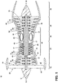
- FIG. 1 is a schematic cross-sectional diagram of a gas turbine engine, which can comprise a gas turbine engine 10, for an aircraft.
- the engine 10 has a generally longitudinally extending axis or centerline 12 extending forward 14 to aft 16.
- the engine 10 includes, in downstream serial flow relationship, a fan section 18 including a fan 20, a compressor section 22 including a booster or low pressure (LP) compressor 24 and a high pressure (HP) compressor 26, a combustion section 28 including a combustor 30, a turbine section 32 including a HP turbine 34, and a LP turbine 36, and an exhaust section 38.
- the compressor section 22, combustion section 28, and turbine section 32 are in axial flow arranged and enclosed within a core casing 46.
- the fan section 18 includes a fan casing 40 surrounding the fan 20.
- the fan 20 includes a plurality of fan blades 42 disposed radially about the centerline 12.
- the HP compressor 26, the combustor 30, and the HP turbine 34 form a core 44 of the engine 10, which generates combustion gases.
- the core 44 is surrounded by the core casing 46, which can be coupled with the fan casing 40. At least a portion of the fan casing 40 encircles the core casing 46 to define an annular bypass channel 47.
- a LP drive shaft or spool 50 which is disposed coaxially about the centerline 12 of the engine 10 within the larger diameter annular HP spool 48, drivingly connects the LP turbine 36 to the LP compressor 24 and fan 20.
- the portions of the engine 10 mounted to and rotating with either or both of the spools 48, 50 are also referred to individually or collectively as a rotor 51.
- the LP compressor 24 and the HP compressor 26 respectively include a plurality of compressor stages 52, 54, in which a set of compressor blades 56, 58 rotate relative to a corresponding set of static compressor vanes 60, 62 (also called a nozzle), each set comprising a pair, to compress or pressurize the stream of fluid passing through the stage.
- a single compressor stage 52, 54 multiple compressor blades 56, 58 can be provided in a ring and can extend radially outwardly relative to the centerline 12, from a blade platform to a blade tip, while the corresponding static compressor vanes 60, 62 are positioned downstream of and adjacent to the rotating blades 56, 58.
- blades 56, 58 for a stage of the compressor can be mounted to a disk 53, which is mounted to the corresponding one of the HP and LP spools 48, 50, with each stage having its own disk.
- the vanes 60, 62 are mounted to the core casing 46 in a circumferential arrangement about the rotor 51.
- the compressor is not limited to an axial orientation and can be oriented axially, radially, or in a combined manner.
- the LP compressor 24 and the HP compressor 26 can further include at least one guide vane which can be an inlet guide vane 55 positioned on the upstream end of the compressor section 22 and an outlet guide vane 57 positioned on the downstream end of the compressor section 22.
- the vanes are not limited to one type and can be for example non-variable stator vanes or stator vanes.
- the HP turbine 34 and the LP turbine 36 respectively include a plurality of turbine stages 64, 66, in which a set of turbine blades 68, 70 are rotated relative to a corresponding set of static turbine vanes 72, 74 (also called a nozzle) to extract energy from the stream of fluid passing through the stage.
- a single turbine stage 64, 66 multiple turbine blades 68, 70 can be provided in a ring and can extend radially outwardly relative to the centerline 12, from a blade platform to a blade tip, while the corresponding static turbine vanes 72, 74 are positioned upstream of and adjacent to the rotating blades 68, 70. It is noted that the number of blades, vanes, and turbine stages shown in Figure 1 were selected for illustrative purposes only, and that other numbers are possible.
- the rotating fan 20 supplies ambient air to the LP compressor 24, which then supplies pressurized ambient air to the HP compressor 26, which further pressurizes the ambient air.
- the pressurized air from the HP compressor 26 is mixed with fuel in the combustor 30 and ignited, thereby generating combustion gases. Some work is extracted from these gases by the HP turbine 34, which drives the HP compressor 26.
- the combustion gases are discharged into the LP turbine 36, which extracts additional work to drive the LP compressor 24, and the exhaust gas is ultimately discharged from the engine 10 via the exhaust section 38.
- the driving of the LP turbine 36 drives the LP spool 50 to rotate the fan 20 and the LP compressor 24.
- the ambient air supplied by the fan 20 can bypass the engine core 44 as a bypass air flow and be used for cooling of portions, especially hot portions, of the engine 10, and/or used to cool or power other aspects of the aircraft.
- the hot portions of the engine are normally downstream of the combustor 30, especially the turbine section 32, with the HP turbine 34 being the hottest portion as it is directly downstream of the combustion section 28.
- Hot portions of the engine also exist within the compressor section 22 and therefore the ambient air supplied by the fan 20 or cooler air from the compressor can be utilized, but not limited to, cooling portions of the compressor section 22.
- the bypass air flow can pass through a heat exchanger 76, located upstream of the compressor 26, within the bypass air flow of the bypass channel 47. Though illustrated within the bypass channel 47, the location of the heat exchanger 76 is not limited to the bypass channel and can be located at any suitable position within the engine 10.
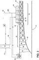
- a schematic of the compressor section 22 further illustrates an inner compressor casing 80 comprising, the rotor 51, and an outer compressor casing 82 disposed within the core casing 46.
- the multiple, axially arranged stages 52, 54 of paired rotating blades 58 and vanes 62 are located between the outer compressor casing 82 and the inner compressor casing 80.
- a closed loop cooling circuit 84 having a pump 86, an intercooler 88, a heat exchanger 76, and a coolant conduit 90 passing through the pump 86, intercooler 88, heat exchanger 76, and at least some of the vanes 62 is located proximate the compressor section 22.
- the coolant conduit 90 allows liquid coolant to travel in the closed loop cooling circuit 84 by utilizing the pump 86 to pump coolant through the coolant conduit 90.
- the intercooler 88 and heat exchanger 76 can be any suitable type of heat exchanger, including, but not limited to surface coolers. Furthermore the intercooler 88 can comprise an inlet guide vane 55 and the heat exchanger 76 can comprise or be located adjacent to an outlet guide vane 57.
- the core casing 46 includes passages 92 through the outer compressor casing 82 each including an inlet 94 and an outlet 96 to allow the coolant conduit 90 access to and from the vanes 62.
- the coolant conduit 90 connects the heat exchanger 76 to at least one of the plurality of vanes 62 through the inlet 94 and then to the pump 86 via the outlet 96 after which the coolant conduit 90 is connected back to the heat exchanger 76.
- the engine 10 can further comprise a gearbox 45 that can be located at any suitable position within the engine 10 such that it connects the fan 20 of the fan section 18 to the spool 48, 50 of the core 44.
- the gearbox allows the fan to run at a different speed than the engine.
- the closed loop cooling circuit 84 includes a connection via the coolant conduit 90 from the heat exchanger 76 to the intercooler 88 and back to the heat exchanger 76 wherein the intercooler 88 is provided on the gearbox 45.
- the intercooler 88 can be disposed on the gearbox 45 and the core casing 46.
- An optional flow control device for example, but not limited to, a control valve, can be included in the loop such that coolant flow to the intercooler 88 can be either on, off, or modulated depending on operating conditions.
- FIG. 3 a flow chart illustrating a method 200 of cooling a gas engine turbine by first 202 introducing fan air 75 as a cooling fluid to the heat exchanger 76.
- This fan air 75 passes over the heat exchanger 76 to cool liquid coolant to form cooled coolant 98 within the heat exchanger 76.
- the cooled coolant 98 is routed from the heat exchanger 76 through 206 the vanes 62 and to 208 the intercooler 88 to cool the vanes and the intercooler.
- the liquid coolant draws heat from the vanes 62 and the intercooler 88 forming heated coolant 100.
- step 210 the heated coolant 100 flows from the vanes 62 to the pump 86, which can comprise a compressor, and then continues to the heat exchanger 76 where heat is further rejected from the coolant to the bypass air to cool the coolant to form the cooled coolant 98.
- the cooled coolant 98 is then returned to the vanes 62 and to the intercooler 88 and the process repeats.
- the cooled coolant 98 can be used to cool other items such as the gearbox 45 or core casing 46 via the intercooler 88.
- the pump is a pressure rise device, for example a pump or a compressor.
- the pump or compressor can be driven using work from the engine for example a connecting gear on the shaft, or using electrical power generated from the engine.
- an intercooler as described in the disclosure above is a mechanical device that can be any type of heat exchanger and should not be confused with the thermodynamic cycle of cooling a compressor stage or set of stages, i.e. intercooling.
Landscapes
- Engineering & Computer Science (AREA)
- Chemical & Material Sciences (AREA)
- Combustion & Propulsion (AREA)
- Mechanical Engineering (AREA)
- General Engineering & Computer Science (AREA)
- Physics & Mathematics (AREA)
- Thermal Sciences (AREA)
- Fluid Mechanics (AREA)
- Structures Of Non-Positive Displacement Pumps (AREA)
Applications Claiming Priority (1)
| Application Number | Priority Date | Filing Date | Title |
|---|---|---|---|
| US14/957,978 US20170159675A1 (en) | 2015-12-03 | 2015-12-03 | Closed loop cooling method for a gas turbine engine |
Publications (1)
| Publication Number | Publication Date |
|---|---|
| EP3176409A1 true EP3176409A1 (fr) | 2017-06-07 |
Family
ID=57391908
Family Applications (1)
| Application Number | Title | Priority Date | Filing Date |
|---|---|---|---|
| EP16200336.2A Withdrawn EP3176409A1 (fr) | 2015-12-03 | 2016-11-23 | Procédé de refroidissement en circuit fermé pour une turbomachine |
Country Status (6)
| Country | Link |
|---|---|
| US (1) | US20170159675A1 (fr) |
| EP (1) | EP3176409A1 (fr) |
| JP (1) | JP2017101675A (fr) |
| CN (1) | CN106989065A (fr) |
| BR (1) | BR102016028337A2 (fr) |
| CA (1) | CA2949685A1 (fr) |
Families Citing this family (7)
| Publication number | Priority date | Publication date | Assignee | Title |
|---|---|---|---|---|
| WO2019033243A1 (fr) * | 2017-08-14 | 2019-02-21 | 大连理工大学 | Appareil à aubes de turbine de refroidissement à haut rendement avec noyau d'absorption de liquide à double couche et sans ouverture |
| US11022037B2 (en) | 2018-01-04 | 2021-06-01 | General Electric Company | Gas turbine engine thermal management system |
| US10941706B2 (en) | 2018-02-13 | 2021-03-09 | General Electric Company | Closed cycle heat engine for a gas turbine engine |
| US11143104B2 (en) | 2018-02-20 | 2021-10-12 | General Electric Company | Thermal management system |
| CN108443236A (zh) * | 2018-03-05 | 2018-08-24 | 清华大学 | 一种压气机静叶角区分离控制装置及其控制方法 |
| US11015534B2 (en) | 2018-11-28 | 2021-05-25 | General Electric Company | Thermal management system |
| US12044170B2 (en) * | 2022-09-08 | 2024-07-23 | General Electric Company | Closed-loop cooling system for a gas turbine engine |
Citations (4)
| Publication number | Priority date | Publication date | Assignee | Title |
|---|---|---|---|---|
| GB1516041A (en) * | 1977-02-14 | 1978-06-28 | Secr Defence | Multistage axial flow compressor stators |
| WO2002038938A1 (fr) * | 2000-11-10 | 2002-05-16 | Kovac Marek | Reacteur a turbine a gaz avec derivation et procede de refroidissement pour fluide caloporteur |
| DE102013211042B3 (de) * | 2013-06-13 | 2014-08-14 | MTU Aero Engines AG | Flugtriebwerk-Gasturbine |
| US8858161B1 (en) * | 2007-11-29 | 2014-10-14 | Florida Turbine Technologies, Inc. | Multiple staged compressor with last stage airfoil cooling |
Family Cites Families (7)
| Publication number | Priority date | Publication date | Assignee | Title |
|---|---|---|---|---|
| US2755064A (en) * | 1950-08-30 | 1956-07-17 | Curtiss Wright Corp | Stator blade positioning means |
| DE4237664A1 (de) * | 1992-11-07 | 1994-05-11 | Asea Brown Boveri | Verfahren zum Betrieb eines Turboverdichters |
| US5722241A (en) * | 1996-02-26 | 1998-03-03 | Westinghouse Electric Corporation | Integrally intercooled axial compressor and its application to power plants |
| US7600382B2 (en) * | 2005-07-20 | 2009-10-13 | Ralls Jr Stephen Alden | Turbine engine with interstage heat transfer |
| GB201206603D0 (en) * | 2012-04-16 | 2012-05-30 | Rolls Royce Plc | Variable stator vane arrangement |
| US20140165570A1 (en) * | 2012-12-18 | 2014-06-19 | United Technologies Corporation | Oscillating heat pipe for thermal management of gas turbine engines |
| US10400675B2 (en) * | 2015-12-03 | 2019-09-03 | General Electric Company | Closed loop cooling method and system with heat pipes for a gas turbine engine |
-
2015
- 2015-12-03 US US14/957,978 patent/US20170159675A1/en not_active Abandoned
-
2016
- 2016-11-22 CA CA2949685A patent/CA2949685A1/fr not_active Abandoned
- 2016-11-23 EP EP16200336.2A patent/EP3176409A1/fr not_active Withdrawn
- 2016-11-30 JP JP2016231922A patent/JP2017101675A/ja active Pending
- 2016-12-02 BR BR102016028337-0A patent/BR102016028337A2/pt not_active Application Discontinuation
- 2016-12-02 CN CN201611095071.XA patent/CN106989065A/zh active Pending
Patent Citations (4)
| Publication number | Priority date | Publication date | Assignee | Title |
|---|---|---|---|---|
| GB1516041A (en) * | 1977-02-14 | 1978-06-28 | Secr Defence | Multistage axial flow compressor stators |
| WO2002038938A1 (fr) * | 2000-11-10 | 2002-05-16 | Kovac Marek | Reacteur a turbine a gaz avec derivation et procede de refroidissement pour fluide caloporteur |
| US8858161B1 (en) * | 2007-11-29 | 2014-10-14 | Florida Turbine Technologies, Inc. | Multiple staged compressor with last stage airfoil cooling |
| DE102013211042B3 (de) * | 2013-06-13 | 2014-08-14 | MTU Aero Engines AG | Flugtriebwerk-Gasturbine |
Also Published As
| Publication number | Publication date |
|---|---|
| JP2017101675A (ja) | 2017-06-08 |
| CN106989065A (zh) | 2017-07-28 |
| CA2949685A1 (fr) | 2017-06-03 |
| BR102016028337A2 (pt) | 2017-07-18 |
| US20170159675A1 (en) | 2017-06-08 |
Similar Documents
| Publication | Publication Date | Title |
|---|---|---|
| US10400675B2 (en) | Closed loop cooling method and system with heat pipes for a gas turbine engine | |
| EP3176408A1 (fr) | Système et procédé de refroidissement intermédiaire pour un moteur à turbine à gaz | |
| CN109723558B (zh) | 包括热管理系统的燃气涡轮发动机及其操作方法 | |
| US20200309033A1 (en) | Method and system for a combined air-oil cooler and fuel-oil cooler heat exchanger | |
| EP3176409A1 (fr) | Procédé de refroidissement en circuit fermé pour une turbomachine | |
| US11384690B2 (en) | System and method of reducing post-shutdown engine temperatures | |
| EP3187716A1 (fr) | Procédé et système de refroidissement de compresseur et de turbine | |
| US11359646B2 (en) | Gas turbine engine with vane having a cooling inlet | |
| EP3121417A1 (fr) | Échangeur de chaleur intégré à un réservoir d'huile | |
| WO2018009259A2 (fr) | Système pour refroidisseur de surface à angles d'ailettes orientés ogv | |
| EP3225785A2 (fr) | Joint de cannelure pour moteur de turbine à gaz | |
| EP3203027A1 (fr) | Aube de turbine à gaz avec refroidissement | |
| EP3901411A1 (fr) | Injecteur d'air tangentiel à refroidissement intermédiaire pour moteurs à turbine à gaz | |
| CN116892450A (zh) | 用于燃气涡轮发动机的热管理系统 | |
| CN118815592A (zh) | 主动间隙控制组件 |
Legal Events
| Date | Code | Title | Description |
|---|---|---|---|
| AK | Designated contracting states |
Kind code of ref document: A1 Designated state(s): AL AT BE BG CH CY CZ DE DK EE ES FI FR GB GR HR HU IE IS IT LI LT LU LV MC MK MT NL NO PL PT RO RS SE SI SK SM TR |
|
| AX | Request for extension of the european patent |
Extension state: BA ME |
|
| PUAI | Public reference made under article 153(3) epc to a published international application that has entered the european phase |
Free format text: ORIGINAL CODE: 0009012 |
|
| STAA | Information on the status of an ep patent application or granted ep patent |
Free format text: STATUS: THE APPLICATION IS DEEMED TO BE WITHDRAWN |
|
| 18D | Application deemed to be withdrawn |
Effective date: 20171208 |