EP3176400A1 - Fan drive with improved variable slippage clutch unit for an internal combustion engine - Google Patents
Fan drive with improved variable slippage clutch unit for an internal combustion engine Download PDFInfo
- Publication number
- EP3176400A1 EP3176400A1 EP16201528.3A EP16201528A EP3176400A1 EP 3176400 A1 EP3176400 A1 EP 3176400A1 EP 16201528 A EP16201528 A EP 16201528A EP 3176400 A1 EP3176400 A1 EP 3176400A1
- Authority
- EP
- European Patent Office
- Prior art keywords
- fan
- clutch
- speed
- shift unit
- unit
- Prior art date
- Legal status (The legal status is an assumption and is not a legal conclusion. Google has not performed a legal analysis and makes no representation as to the accuracy of the status listed.)
- Granted
Links
Images




Classifications
-
- F—MECHANICAL ENGINEERING; LIGHTING; HEATING; WEAPONS; BLASTING
- F01—MACHINES OR ENGINES IN GENERAL; ENGINE PLANTS IN GENERAL; STEAM ENGINES
- F01P—COOLING OF MACHINES OR ENGINES IN GENERAL; COOLING OF INTERNAL-COMBUSTION ENGINES
- F01P7/00—Controlling of coolant flow
- F01P7/02—Controlling of coolant flow the coolant being cooling-air
- F01P7/04—Controlling of coolant flow the coolant being cooling-air by varying pump speed, e.g. by changing pump-drive gear ratio
- F01P7/042—Controlling of coolant flow the coolant being cooling-air by varying pump speed, e.g. by changing pump-drive gear ratio using fluid couplings
-
- F—MECHANICAL ENGINEERING; LIGHTING; HEATING; WEAPONS; BLASTING
- F01—MACHINES OR ENGINES IN GENERAL; ENGINE PLANTS IN GENERAL; STEAM ENGINES
- F01P—COOLING OF MACHINES OR ENGINES IN GENERAL; COOLING OF INTERNAL-COMBUSTION ENGINES
- F01P5/00—Pumping cooling-air or liquid coolants
- F01P5/02—Pumping cooling-air; Arrangements of cooling-air pumps, e.g. fans or blowers
- F01P5/04—Pump-driving arrangements
-
- F—MECHANICAL ENGINEERING; LIGHTING; HEATING; WEAPONS; BLASTING
- F01—MACHINES OR ENGINES IN GENERAL; ENGINE PLANTS IN GENERAL; STEAM ENGINES
- F01P—COOLING OF MACHINES OR ENGINES IN GENERAL; COOLING OF INTERNAL-COMBUSTION ENGINES
- F01P7/00—Controlling of coolant flow
- F01P7/02—Controlling of coolant flow the coolant being cooling-air
- F01P7/04—Controlling of coolant flow the coolant being cooling-air by varying pump speed, e.g. by changing pump-drive gear ratio
- F01P7/046—Controlling of coolant flow the coolant being cooling-air by varying pump speed, e.g. by changing pump-drive gear ratio using mechanical drives
-
- F—MECHANICAL ENGINEERING; LIGHTING; HEATING; WEAPONS; BLASTING
- F01—MACHINES OR ENGINES IN GENERAL; ENGINE PLANTS IN GENERAL; STEAM ENGINES
- F01P—COOLING OF MACHINES OR ENGINES IN GENERAL; COOLING OF INTERNAL-COMBUSTION ENGINES
- F01P7/00—Controlling of coolant flow
- F01P7/02—Controlling of coolant flow the coolant being cooling-air
- F01P7/08—Controlling of coolant flow the coolant being cooling-air by cutting in or out of pumps
- F01P7/081—Controlling of coolant flow the coolant being cooling-air by cutting in or out of pumps using clutches, e.g. electro-magnetic or induction clutches
- F01P7/082—Controlling of coolant flow the coolant being cooling-air by cutting in or out of pumps using clutches, e.g. electro-magnetic or induction clutches using friction clutches
-
- F—MECHANICAL ENGINEERING; LIGHTING; HEATING; WEAPONS; BLASTING
- F04—POSITIVE - DISPLACEMENT MACHINES FOR LIQUIDS; PUMPS FOR LIQUIDS OR ELASTIC FLUIDS
- F04D—NON-POSITIVE-DISPLACEMENT PUMPS
- F04D27/00—Control, e.g. regulation, of pumps, pumping installations or pumping systems specially adapted for elastic fluids
- F04D27/004—Control, e.g. regulation, of pumps, pumping installations or pumping systems specially adapted for elastic fluids by varying driving speed
-
- F—MECHANICAL ENGINEERING; LIGHTING; HEATING; WEAPONS; BLASTING
- F04—POSITIVE - DISPLACEMENT MACHINES FOR LIQUIDS; PUMPS FOR LIQUIDS OR ELASTIC FLUIDS
- F04D—NON-POSITIVE-DISPLACEMENT PUMPS
- F04D29/00—Details, component parts, or accessories
- F04D29/26—Rotors specially for elastic fluids
- F04D29/32—Rotors specially for elastic fluids for axial flow pumps
- F04D29/325—Rotors specially for elastic fluids for axial flow pumps for axial flow fans
- F04D29/329—Details of the hub
-
- F—MECHANICAL ENGINEERING; LIGHTING; HEATING; WEAPONS; BLASTING
- F16—ENGINEERING ELEMENTS AND UNITS; GENERAL MEASURES FOR PRODUCING AND MAINTAINING EFFECTIVE FUNCTIONING OF MACHINES OR INSTALLATIONS; THERMAL INSULATION IN GENERAL
- F16H—GEARING
- F16H3/00—Toothed gearings for conveying rotary motion with variable gear ratio or for reversing rotary motion
- F16H3/02—Toothed gearings for conveying rotary motion with variable gear ratio or for reversing rotary motion without gears having orbital motion
- F16H3/08—Toothed gearings for conveying rotary motion with variable gear ratio or for reversing rotary motion without gears having orbital motion exclusively or essentially with continuously meshing gears, that can be disengaged from their shafts
- F16H3/087—Toothed gearings for conveying rotary motion with variable gear ratio or for reversing rotary motion without gears having orbital motion exclusively or essentially with continuously meshing gears, that can be disengaged from their shafts characterised by the disposition of the gears
- F16H3/089—Toothed gearings for conveying rotary motion with variable gear ratio or for reversing rotary motion without gears having orbital motion exclusively or essentially with continuously meshing gears, that can be disengaged from their shafts characterised by the disposition of the gears all of the meshing gears being supported by a pair of parallel shafts, one being the input shaft and the other the output shaft, there being no countershaft involved
-
- F—MECHANICAL ENGINEERING; LIGHTING; HEATING; WEAPONS; BLASTING
- F16—ENGINEERING ELEMENTS AND UNITS; GENERAL MEASURES FOR PRODUCING AND MAINTAINING EFFECTIVE FUNCTIONING OF MACHINES OR INSTALLATIONS; THERMAL INSULATION IN GENERAL
- F16H—GEARING
- F16H35/00—Gearings or mechanisms with other special functional features
- F16H35/10—Arrangements or devices for absorbing overload or preventing damage by overload
-
- F—MECHANICAL ENGINEERING; LIGHTING; HEATING; WEAPONS; BLASTING
- F16—ENGINEERING ELEMENTS AND UNITS; GENERAL MEASURES FOR PRODUCING AND MAINTAINING EFFECTIVE FUNCTIONING OF MACHINES OR INSTALLATIONS; THERMAL INSULATION IN GENERAL
- F16H—GEARING
- F16H9/00—Gearings for conveying rotary motion with variable gear ratio, or for reversing rotary motion, by endless flexible members
- F16H9/02—Gearings for conveying rotary motion with variable gear ratio, or for reversing rotary motion, by endless flexible members without members having orbital motion
- F16H9/04—Gearings for conveying rotary motion with variable gear ratio, or for reversing rotary motion, by endless flexible members without members having orbital motion using belts, V-belts, or ropes
Definitions
- the present invention relates to a fan drive for an internal combustion engine, in particular for an internal combustion engine provided in agricultural vehicles, such as harvesters, tractors and the like, or construction vehicles, such as loaders, excavators and the like.
- a fan drive is normally provided in a cooling system of an internal combustion engine.
- a fan is used to provide an air flow for cooling a diesel engine of a working vehicle, such as an agricultural vehicle or a construction vehicle.
- the fan is designed to provide the appropriate cooling effect in the most severe working condition of the IC engine. The latter however seldom occurs so that power absorption of the fan is excessively high during other working conditions.
- variable slippage fluid clutch to couple in a torque transfer mode a driving shaft of the internal combustion engine to the fan in order to control the rotating speed of the fan with respect to the rotating speed of the driving shaft and thus decrease power absorption.
- the clutch unit is controlled so that the fan has a low or null rotational speed. Without a significant cooling from the fan, the engine quickly reaches a predefined optimal working temperature, thus reducing low efficiency transients.
- power is saved when the fan is stopped or rotates at low speed. Reduction of the fan speed with respect to the driving shaft can also be operated during running of the vehicle according to known control strategies.
- Efficiency of a fluid variable slippage clutch is in general satisfactory.
- the clutch shall transfer an intermediate level of torque, e.g. the fan is at a medium range speed, and at the same time the driving shaft speed is relatively high.
- a non negligible amount of power is wasted due to the combination of slippage an transferred torque. It is therefore the scope of the present invention to further decrease power consumption of a fan driven by a fluid slippage clutch unit and, at the same time, to provide an effective cooling to the IC engine in all working conditions.
- a fan drive for a working vehicle comprising a fluid slippage clutch and a fan in series to the fluid slippage clutch and a speed shift unit connected in series to the fan and the fluid slippage clutch and configured to discretely provide a first non-zero speed ratio and at least a second non-zero speed ratio
- the speed shift unit comprising a clutch unit having a first and at least a second clutch configured to alternatively connect the first or the second non-zero speed ratios to the fan.
- a control unit of the fan drive is programmed to efficiently switch between a slippage fan speed control mode operated by the fluid slippage clutch and a modulating fan speed control mode operated by the speed shift unit.
- a retrofit method is provided in order to upgrade an existing fan drive provided with an existing fluid slippage clutch connected in series to the fan.
- numeral 1 refers to an internal combustion engine for a working vehicle that is cooled by a fan drive 2 driven by a shaft 3 of IC engine 1.
- Shaft 3 is connected with a fixed speed ratio to a crankshaft of IC engine 1.
- Fan drive 2 comprises, in series, a discrete speed shift unit 4 configured to define at least a first and a second non-zero speed ratio SR1, SR2 and possibly a neutral or zero ratio SR0, a fluid or wet slippage clutch 5 controllable so that speed of an output shaft or member 6 lags or pairs the speed of an input shaft or member 7, and a fan 8 driven by speed shift unit 4 and fluid slippage clutch 5.
- a discrete speed shift unit 4 configured to define at least a first and a second non-zero speed ratio SR1, SR2 and possibly a neutral or zero ratio SR0
- a fluid or wet slippage clutch 5 controllable so that speed of an output shaft or member 6 lags or pairs the speed of an input shaft or member 7, and a fan 8 driven by speed shift unit 4 and fluid slippage clutch 5.
- Discrete speed shift unit 4 comprises, according to a preferred embodiment of the invention, a first endless flexible drive 9 defining the first speed ratio, a second endless flexible drive 10 set in parallel to first endless flexible drive 9 with respect to shaft 3 and defining the second speed ratio, and a clutch unit 11 to select whether fan 8 is driven either by the first endless flexible drive 9 or by the second endless flexible drive 10.
- clutch unit 11 that preferably comprises a first and a second on-off clutch each of which is placed in order to selectively connect endless flexible drive 9 or endless flexible drive 10 to fan 8.
- Each on-off clutch initially slips during transients when connecting either endless flexible drive 9 or endless flexible drive 10 to fan 8 ( figure 1 shows only a functional sketch).
- slippage is dry slippage obtained by one or more friction disks.
- Each clutch can be hydraulic, electro-magnetic or purely mechanical.
- first endless flexible drive 9 comprises a driving pulley 12 connected in a torque transmitting manner to shaft 3, a driven pulley 13 and a belt 14 to connect in a torque transmitting manner pulley 12 to pulley 13.
- Second endless flexible drive 10 comprises a driving pulley 15 connected in a torque transmitting manner to shaft 3 in parallel to pulley 12, a driven pulley 16 and a belt 17 to connect in a torque transmitting manner pulley 15 to pulley 16.
- Shift unit 4 also comprises a driven shaft 18 to which pulleys 13 and 16 are selectively connected in a torque transmitting manner by clutch unit 11 in order to control the speed of fan 8.
- pulleys 13, 16 are free to rotate with respect to driven shaft 18; and clutch unit 11, in a discrete and selective manner, connects either pulley 13 or pulley 16 to driven shaft 18 whilst the other one freely rotates with respect to shaft 18 ( figure 1b ).
- discrete speed shift unit 4 is in the neutral ratio SR0 and shaft 3 is rotating, both pulleys 13, 16 freely rotate with respect to shaft 18 that, in such a condition, is disengaged from driving shaft 3 so that fan 8 is stopped or at a minimum speed.
- pulleys 12 and 15 have different diameters and pulleys 13, 16 have the same diameter in order to define first and second speed ratio SR1, SR2.
- first and second speed ratio can be unitary and the other one is either below or above 1 depending on the IC engine models.
- drives 9, 10 with chain and sprockets (not shown) having the same functions as pulleys 12, 13, 15, 16 and belts 14, 17.
- discrete shift unit 4 defines first and second speed ratio and, possibly, neutral ratio by means of gears or a combination of gear drives and endless flexible drives.
- Discrete shift unit 4 has a high torque transfer efficiency, i.e. ratio between power available on shaft 18 and power applied to shaft 3. Torque transfer efficiency does not take into consideration power absorbed for control and actuation of the components, i.e. power absorbed to switch clutch unit 11. Depending on design requirements, minimum torque transfer efficiency of shift unit 4 can be either 90% or higher. For example, efficiency of belt drives 9, 10 can be 95% or higher. Furthermore efficiency of shift unit 4 remains constant over rotation speed range of fan 8.
- discrete shift unit 4 is upstream to fluid slippage clutch 5 along the torque flow from shaft 3 to fan 8.
- Fluid slippage clutch 5 can be for example a mechanically controlled fluid friction clutch having input shaft 7 and output shaft 6 connected to respective armatures (not shown) inside a working chamber filled with a viscous fluid, for example a silicone-based oil.
- a viscous fluid for example a silicone-based oil.
- rotational movement is transmitted to the viscous fluid from the armature connected to input shaft 7; and to the armature connected to output shaft 6 from the viscous fluid, for example by shear forces within the fluid.
- Mechanical control can be implemented via a hydraulic control valve to set the slip of the fluid friction clutch based on metering the amount of viscous fluid within the working chamber.
- viscous fluid tends to leak out the working chamber so that armatures can more easily slip one with respect to the other and a low torque is thus transmitted.
- the valve is closed after a large amount of viscous fluid is injected in the working chamber, the fluid is trapped and transmitted torque increases, thus lowering slippage.
- fluid slippage clutch 5 has an efficiency that is continuously variable depending on the working condition of fan 8.
- torque transfer efficiency of fluid slippage clutch 5 ranges from a maximum to a minimum of approximately 65% excluding power absorption for the actuation of the valve. The maximum efficiency is reached when either transmitted torque is low and slippage is maximum, i.e. the fan is stopped or at its minimum speed, or transmitted torque is maximum and slippage is low, i.e. the fan is at its maximum speed. Minimum efficiency is experienced where, approximately at mid fan speed range, both slippage and transmitted torque are at an intermediate level.
- dashed curve and dotted curve are proximal at both maximum and minimum fan speed and, from such endpoints, progressively depart one from the other to reach a maximum difference in an intermediate speed range.
- Fluid slippage clutch 5 is controllable by a discrete control such that valve pulsates between an open an a closed position. This can be implemented by an ON/OFF valve controlled by a PWM controller. Other controls are applicable, for example a proportional control of a servovalve.
- input shaft 7 of fluid slippage clutch 5 is rigidly connected to, and preferably a single body with, driven shaft 18.
- Fan 8 is connected in order to rotate at the same speed as that of output shaft 6.
- Fluid slippage clutch 5 and clutch unit 11 are controlled by an electronic control unit 20 that may be dedicated to the control of fan drive 2 or be embedded in an electronic control system of IC engine 1.
- fan 8 is a fixed blade fan, i.e. blades 21 have a fixed orientation when fan 8 is stopped.
- fan 8 may comprise rotatable blades configured to change the pitch of fan 8.
- fluid slippage clutch 5 is surrounded by blades 21 in order to reduce axial dimension.
- output shaft 6 and input shaft 7 can be substituted by mechanical members having different shapes.
- output member 6 can be shaped as a hub of fan 8 and input member 7 can be a flange for connection with shift unit 4.
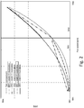
- Figure 2 compares different fan power consumptions of fan drive 2 over the fan working speed compared to the power consumption (dotted) of a theoretical condition where fan 8 is rigidly connected to shaft 3 and IC engine 1 ramps up.
- fan 8 is rigidly connected to shaft 3 and IC engine 1 ramps up.
- control unit 20 determines a target speed FST of fan 8 and checks whether the ratio of FST and the speed of shaft 3 ES is higher than SR1.
- fluid slippage unit 5 is set to a maximum torque transfer mode, i.e. full engagement, and control unit 20 switches clutch unit 11, i.e. between SR1 and SR2, in order to follow the predetermined characteristic curve that can be rectilinear, e.g. dash-dot-dot of figure 2 .
- control unit 20 switches clutch unit 11, i.e. between SR1 and SR2, in order to follow the predetermined characteristic curve that can be rectilinear, e.g. dash-dot-dot of figure 2 .
- SR1 is set and the fan speed is controlled through fluid slippage clutch 5, e.g. according to modulation with a non 100% working cycle of the control valve, to follow FST. This corresponds to large dashed line of figure 2 .
- the fan speed FS is controlled in closed loop.
- control unit 20 checks whether FST is lower than a predefined speed threshold, e.g. threshold TC for cold starting of IC engine 1.
- a predefined speed threshold e.g. threshold TC for cold starting of IC engine 1.
- Control unit 20 checks for cold starting before checking whether the ratio of FST and the speed of shaft 3 ES is higher than SR1.
- FST is lower than TC
- control unit 20 ensures that shift unit 4 is in the neutral ratio SR0, i.e. driven shaft 18 is disconnected from shaft 3. In such a condition, fan 8 is stopped or rotates at its minimum speed.
- ratio FST/ES is checked over SR1 and the above paragraphs apply.
- power consumption is optimized both in a lower fan speed range and a higher fan speed range.
- the large dashed line and the dash-dot-dot line that are close to dotted line, which represents a condition where efficiency of transmission between shaft 3 and fan 8 is unitary.
- the dotted line refers to a layout where fan 8 is rigidly connected to shaft 3.
- dissipation is reduced because slippage occurs at a lower speed.
- dissipation is reduced because the modulation between SR1 and SR2 is operated at higher efficiency, i.e. excluding fluid slippage.
- Speed shift unit 4 introduces a discrete double speed range within fan drive 2 that is simple to implement and at the same time advantageous, depending on the control strategy, to reduce power losses due to slippage of fluid slippage clutch 5.
- SR1 and SR2 it is possible to design a fan drive having characteristic curves that either are below, e.g. large dashed curve, the characteristic curve relative to a slippage only control, i.e. dashed curve of figure 2 ; or intercept such dashed curve and extend in a region of increased efficiency.
- provision of clutch unit 11 to switch between SR1 and SR2 ensures, due to slipping of clutch unit 11 during transients of connection, the implementation of a wide range of control strategies in combination with fluid slippage clutch 5.
- Speed shift unit 4 is upstream of fluid slippage clutch 5 in order to reduce the impact on existing fan drives where the fluid slippage clutch 5 is attached to fan 8.
- existing fan drives comprise fixed blades 21 surrounding fluid slippage clutch 5 and attached directly to output member 6, which is therefore the hub of fan 8.
- fluid slippage clutch unit 5, being in series to shift unit 4 helps to smooth the noise during shifting of unit 4, in particular when unit 4 modulates along dash-dot line and/or dash-dot-dot line of figure 2 .
- Provision of neutral ratio SR0 provides an additional flexibility of fan drive 2 that can also implement a power saving strategy for cold start of IC engine 1.
- speed shift unit 4 has a minimum torque transfer efficiency greater than that of fluid slippage clutch 5.
- speed shift unit 4 may comprise belt drives, either friction or synchronous, or chain drives or gears in order to provide SR1 and SR2.
- shift unit 4 or slippage clutch 5 or both are configured to be controlled and are indeed controlled according to a pulse width modulation strategy.
- Actuation of shift 4 or slippage clutch 5 can be either electric, hydraulic, mechanic, magnetic or any combination thereof.
- Provision of on-off clutches within clutch unit 11 makes PWM control easier to implement.
- fluid slippage clutch 5 comprises a magnetoreological fluid that changes its viscosity depending on a variable magnetic field interacting with the fluid and generated for example by electromagnetic coils.
- a magnetoreological fluid is used in a fluid slippage clutch, the functioning and the structure are similar to those of a fluid friction clutch except that a fixed amount of fluid fills the working chamber and the level of slippage is mainly controlled by changing the viscosity of the fluid through a variable magnetic field.
- fluid slippage clutch 5 can be omitted and, in such a case, fan 8 is rigidly connected to driven shaft 18. Accordingly, the power absorbed by fan 8 is shown by dash-dot and dash-dot-dot lines of figure 2 .
- speed shift 4 may also be configured to provide a third gear ratio.
- third gear ratio a further belt or chain shall be provided in parallel to belts 14 and 17 with respect to shaft 3.
- a further clutch, in particular an on-off clutch, functionally identical to those of clutch unit 11 shall be provided in order to provide modulation and, if the case, also full disengagement to stop fan 8 when cold starting of IC engine 4.
Landscapes
- Engineering & Computer Science (AREA)
- General Engineering & Computer Science (AREA)
- Mechanical Engineering (AREA)
- Chemical & Material Sciences (AREA)
- Combustion & Propulsion (AREA)
- Hydraulic Clutches, Magnetic Clutches, Fluid Clutches, And Fluid Joints (AREA)
Abstract
Description
- The present invention relates to a fan drive for an internal combustion engine, in particular for an internal combustion engine provided in agricultural vehicles, such as harvesters, tractors and the like, or construction vehicles, such as loaders, excavators and the like.
- A fan drive is normally provided in a cooling system of an internal combustion engine. In particular a fan is used to provide an air flow for cooling a diesel engine of a working vehicle, such as an agricultural vehicle or a construction vehicle.
- The fan is designed to provide the appropriate cooling effect in the most severe working condition of the IC engine. The latter however seldom occurs so that power absorption of the fan is excessively high during other working conditions.
- It is known to provide a variable slippage fluid clutch to couple in a torque transfer mode a driving shaft of the internal combustion engine to the fan in order to control the rotating speed of the fan with respect to the rotating speed of the driving shaft and thus decrease power absorption. For example, when the IC engine is started from a cold condition, e.g. when the vehicle is parked and the IC engine is substantially at the environment temperature, the clutch unit is controlled so that the fan has a low or null rotational speed. Without a significant cooling from the fan, the engine quickly reaches a predefined optimal working temperature, thus reducing low efficiency transients. In addition, power is saved when the fan is stopped or rotates at low speed. Reduction of the fan speed with respect to the driving shaft can also be operated during running of the vehicle according to known control strategies.
- Efficiency of a fluid variable slippage clutch is in general satisfactory. However there are certain fan working conditions wherein the clutch shall transfer an intermediate level of torque, e.g. the fan is at a medium range speed, and at the same time the driving shaft speed is relatively high. In such a working condition a non negligible amount of power is wasted due to the combination of slippage an transferred torque. It is therefore the scope of the present invention to further decrease power consumption of a fan driven by a fluid slippage clutch unit and, at the same time, to provide an effective cooling to the IC engine in all working conditions.
- The scope of the present invention is achieved with a fan drive for a working vehicle comprising a fluid slippage clutch and a fan in series to the fluid slippage clutch and a speed shift unit connected in series to the fan and the fluid slippage clutch and configured to discretely provide a first non-zero speed ratio and at least a second non-zero speed ratio, the speed shift unit comprising a clutch unit having a first and at least a second clutch configured to alternatively connect the first or the second non-zero speed ratios to the fan.
- Additional features of the invention are comprised in the dependent claims. In particular a control unit of the fan drive is programmed to efficiently switch between a slippage fan speed control mode operated by the fluid slippage clutch and a modulating fan speed control mode operated by the speed shift unit.
- Furthermore, a retrofit method is provided in order to upgrade an existing fan drive provided with an existing fluid slippage clutch connected in series to the fan.
- For a better understanding of the present invention, the latter will further be disclosed with reference to the accompanying figures in which:
-
figure 1a ,1b and 1c are respective schematic views in different working conditions of a fan drive according to the present invention; -
figure 2 is a plot of characteristic curves of power absorbed by the fan according to different control strategies; -
figure 3 is a flowchart of a preferred control strategy of the fan drive infigure 1 ; and -
figure 4 is a comparison of the power loss over the fan rotating speed according to prior art and after implementation of a control strategy according tofigure 3 . - In
figure 1 ,numeral 1 refers to an internal combustion engine for a working vehicle that is cooled by afan drive 2 driven by ashaft 3 ofIC engine 1. Shaft 3 is connected with a fixed speed ratio to a crankshaft ofIC engine 1. -
Fan drive 2 comprises, in series, a discretespeed shift unit 4 configured to define at least a first and a second non-zero speed ratio SR1, SR2 and possibly a neutral or zero ratio SR0, a fluid orwet slippage clutch 5 controllable so that speed of an output shaft ormember 6 lags or pairs the speed of an input shaft or member 7, and a fan 8 driven byspeed shift unit 4 andfluid slippage clutch 5. - Discrete
speed shift unit 4 comprises, according to a preferred embodiment of the invention, a first endlessflexible drive 9 defining the first speed ratio, a second endlessflexible drive 10 set in parallel to first endlessflexible drive 9 with respect toshaft 3 and defining the second speed ratio, and aclutch unit 11 to select whether fan 8 is driven either by the first endlessflexible drive 9 or by the second endlessflexible drive 10. In particular, alternative connection of either endlessflexible drive 9 or endlessflexible drive 10 is operated byclutch unit 11 that preferably comprises a first and a second on-off clutch each of which is placed in order to selectively connect endlessflexible drive 9 or endlessflexible drive 10 to fan 8. Each on-off clutch initially slips during transients when connecting either endlessflexible drive 9 or endlessflexible drive 10 to fan 8 (figure 1 shows only a functional sketch). Preferably, slippage is dry slippage obtained by one or more friction disks. Each clutch can be hydraulic, electro-magnetic or purely mechanical. - According to
figure 1 , first endlessflexible drive 9 comprises adriving pulley 12 connected in a torque transmitting manner toshaft 3, a drivenpulley 13 and abelt 14 to connect in a torque transmittingmanner pulley 12 topulley 13. Second endlessflexible drive 10 comprises adriving pulley 15 connected in a torque transmitting manner toshaft 3 in parallel topulley 12, a drivenpulley 16 and abelt 17 to connect in a torque transmittingmanner pulley 15 topulley 16. -
Shift unit 4 also comprises a driven shaft 18 to whichpulleys clutch unit 11 in order to control the speed of fan 8. In particular,pulleys clutch unit 11, in a discrete and selective manner, connects eitherpulley 13 orpulley 16 to driven shaft 18 whilst the other one freely rotates with respect to shaft 18 (figure 1b ). When discretespeed shift unit 4 is in the neutral ratio SR0 andshaft 3 is rotating, bothpulleys shaft 3 so that fan 8 is stopped or at a minimum speed. - According to
figure 1 ,pulleys pulleys - It is also possible to provide
drives pulleys belts - Furthermore it is also possible that
discrete shift unit 4 defines first and second speed ratio and, possibly, neutral ratio by means of gears or a combination of gear drives and endless flexible drives. -
Discrete shift unit 4 has a high torque transfer efficiency, i.e. ratio between power available on shaft 18 and power applied toshaft 3. Torque transfer efficiency does not take into consideration power absorbed for control and actuation of the components, i.e. power absorbed to switchclutch unit 11. Depending on design requirements, minimum torque transfer efficiency ofshift unit 4 can be either 90% or higher. For example, efficiency ofbelt drives shift unit 4 remains constant over rotation speed range of fan 8. - According to
figure 1 ,discrete shift unit 4 is upstream tofluid slippage clutch 5 along the torque flow fromshaft 3 to fan 8. -
Fluid slippage clutch 5 can be for example a mechanically controlled fluid friction clutch having input shaft 7 andoutput shaft 6 connected to respective armatures (not shown) inside a working chamber filled with a viscous fluid, for example a silicone-based oil. In particular, in a fluid friction clutch, rotational movement is transmitted to the viscous fluid from the armature connected to input shaft 7; and to the armature connected tooutput shaft 6 from the viscous fluid, for example by shear forces within the fluid. Mechanical control can be implemented via a hydraulic control valve to set the slip of the fluid friction clutch based on metering the amount of viscous fluid within the working chamber. For example, when the valve is open andinput shaft 6 is running, viscous fluid tends to leak out the working chamber so that armatures can more easily slip one with respect to the other and a low torque is thus transmitted. When the valve is closed after a large amount of viscous fluid is injected in the working chamber, the fluid is trapped and transmitted torque increases, thus lowering slippage. - In view of the above,
fluid slippage clutch 5 has an efficiency that is continuously variable depending on the working condition of fan 8. In particular, throughout the speed range of fan 8, torque transfer efficiency offluid slippage clutch 5 ranges from a maximum to a minimum of approximately 65% excluding power absorption for the actuation of the valve. The maximum efficiency is reached when either transmitted torque is low and slippage is maximum, i.e. the fan is stopped or at its minimum speed, or transmitted torque is maximum and slippage is low, i.e. the fan is at its maximum speed. Minimum efficiency is experienced where, approximately at mid fan speed range, both slippage and transmitted torque are at an intermediate level. This is also qualitatively shown infigure 2 where, as it will be explained in greater detail below, dashed curve and dotted curve are proximal at both maximum and minimum fan speed and, from such endpoints, progressively depart one from the other to reach a maximum difference in an intermediate speed range. -
Fluid slippage clutch 5 is controllable by a discrete control such that valve pulsates between an open an a closed position. This can be implemented by an ON/OFF valve controlled by a PWM controller. Other controls are applicable, for example a proportional control of a servovalve. - According to the embodiment of
figure 1 , input shaft 7 offluid slippage clutch 5 is rigidly connected to, and preferably a single body with, driven shaft 18. Fan 8 is connected in order to rotate at the same speed as that ofoutput shaft 6. -
Fluid slippage clutch 5 andclutch unit 11 are controlled by anelectronic control unit 20 that may be dedicated to the control offan drive 2 or be embedded in an electronic control system ofIC engine 1. - According to a preferred embodiment, fan 8 is a fixed blade fan, i.e.
blades 21 have a fixed orientation when fan 8 is stopped. As an alternative, fan 8 may comprise rotatable blades configured to change the pitch of fan 8. Furthermore,fluid slippage clutch 5 is surrounded byblades 21 in order to reduce axial dimension. To this regard,output shaft 6 and input shaft 7 can be substituted by mechanical members having different shapes. For example,output member 6 can be shaped as a hub of fan 8 and input member 7 can be a flange for connection withshift unit 4. -
Figure 2 compares different fan power consumptions offan drive 2 over the fan working speed compared to the power consumption (dotted) of a theoretical condition where fan 8 is rigidly connected toshaft 3 andIC engine 1 ramps up. In particular: - Dashed curve shows power consumption of the combination of fan 8 and
fluid slippage clutch 5 whereengine 1 is kept at a high constant speed,shift unit 4 is switched at SR2 andslippage clutch 5 is controlled to ramp up the speed of fan 8; - Large dashed curve shows power consumption of the combination of fan 8 and
slippage clutch 5 whenshift unit 4 is switched at SR1, SR2 being greater than SR1, and speed ofIC engine 1 is constant as above. Ramping of the fan is obtained by controllingslippage clutch 5; - Continuous curve (partially superimposed to dashed curve) shows power consumption of the combination of fan 8,
slippage clutch 5 whenshift unit 4 is switched at SR2 and speed ofIC engine 1 is constant as above. Ramping of the fan is obtained by controllingslippage clutch 5; - Dash-dot line shows power consumption when
slippage clutch 5 is fully engaged, i.e. minimum or null slippage, andclutch unit 11 is controlled to selectively switch, e.g. pulse-width modulate, between SR0 and SR1 in order to obtain a predefined characteristic curve. Modulation between SR0 and SR1 can be controlled such that the line is rectilinear; - Dash-dot-dot line shows power consumption when
slippage clutch 5 is fully engaged, i.e. minimum or null slippage, andclutch unit 11 is controlled, e.g. modulated, between SR1 and SR2 as discussed above for SR0 and SR1. - According to a preferred control method of fan drive 2 (
figure 3 ),control unit 20 determines a target speed FST of fan 8 and checks whether the ratio of FST and the speed ofshaft 3 ES is higher than SR1. - In the affirmative,
fluid slippage unit 5 is set to a maximum torque transfer mode, i.e. full engagement, andcontrol unit 20 switchesclutch unit 11, i.e. between SR1 and SR2, in order to follow the predetermined characteristic curve that can be rectilinear, e.g. dash-dot-dot offigure 2 . Whenfluid slippage clutch 5 is PWM controlled, full engagement ofclutch 5 is realized by setting the maximum amount of fluid in the working chamber and by fully closing the control valve for the 100% of the working cycle (PWM=100 in left branch offigure 3 ). - In the negative, SR1 is set and the fan speed is controlled through
fluid slippage clutch 5, e.g. according to modulation with a non 100% working cycle of the control valve, to follow FST. This corresponds to large dashed line offigure 2 . - As shown in
figure 3 the fan speed FS is controlled in closed loop. - According to an option, also included in
figure 3 ,control unit 20 checks whether FST is lower than a predefined speed threshold, e.g. threshold TC for cold starting ofIC engine 1.Control unit 20 checks for cold starting before checking whether the ratio of FST and the speed ofshaft 3 ES is higher than SR1. In case FST is lower than TC,control unit 20 ensures thatshift unit 4 is in the neutral ratio SR0, i.e. driven shaft 18 is disconnected fromshaft 3. In such a condition, fan 8 is stopped or rotates at its minimum speed. In the negative, ratio FST/ES is checked over SR1 and the above paragraphs apply. - According to the method of the preceding paragraphs power consumption is optimized both in a lower fan speed range and a higher fan speed range. This is confirmed by the large dashed line and the dash-dot-dot line that are close to dotted line, which represents a condition where efficiency of transmission between
shaft 3 and fan 8 is unitary. This is because the dotted line refers to a layout where fan 8 is rigidly connected toshaft 3. In particular, along large dashed curve, dissipation is reduced because slippage occurs at a lower speed. Along dash-dot-dot line, dissipation is reduced because the modulation between SR1 and SR2 is operated at higher efficiency, i.e. excluding fluid slippage. - It is however possible to control
fan drive 2 to introduce the benefit discussed above either at lower or at higher speed range only. - Advantages of
fan drive 2 according to the present invention are as follows. -
Speed shift unit 4 introduces a discrete double speed range withinfan drive 2 that is simple to implement and at the same time advantageous, depending on the control strategy, to reduce power losses due to slippage offluid slippage clutch 5. In particular, due to SR1 and SR2 it is possible to design a fan drive having characteristic curves that either are below, e.g. large dashed curve, the characteristic curve relative to a slippage only control, i.e. dashed curve offigure 2 ; or intercept such dashed curve and extend in a region of increased efficiency. Furthermore, provision ofclutch unit 11 to switch between SR1 and SR2 ensures, due to slipping ofclutch unit 11 during transients of connection, the implementation of a wide range of control strategies in combination withfluid slippage clutch 5. This is because connection of either one of endlessflexible drives shaft 3. This ensures an advantage over speed shifts comprising e.g. synchronizers because in such a case the switch between one gear ratio to another can be operated only over limited ranges of relative speed. -
Speed shift unit 4 is upstream offluid slippage clutch 5 in order to reduce the impact on existing fan drives where thefluid slippage clutch 5 is attached to fan 8. In order to retrofit an existing fan drive it is only necessary to fitspeed shift unit 4 betweenshaft 3 and input shaft or member 7. In particular, existing fan drives comprise fixedblades 21 surroundingfluid slippage clutch 5 and attached directly tooutput member 6, which is therefore the hub of fan 8. Furthermore fluid slippageclutch unit 5, being in series to shiftunit 4, helps to smooth the noise during shifting ofunit 4, in particular whenunit 4 modulates along dash-dot line and/or dash-dot-dot line offigure 2 . Provision of neutral ratio SR0 provides an additional flexibility offan drive 2 that can also implement a power saving strategy for cold start ofIC engine 1. - In order to increase efficiency it is preferable that
speed shift unit 4 has a minimum torque transfer efficiency greater than that offluid slippage clutch 5. In particular,speed shift unit 4 may comprise belt drives, either friction or synchronous, or chain drives or gears in order to provide SR1 and SR2. - In order to provide a simple control, either
shift unit 4 orslippage clutch 5 or both are configured to be controlled and are indeed controlled according to a pulse width modulation strategy. Actuation ofshift 4 orslippage clutch 5 can be either electric, hydraulic, mechanic, magnetic or any combination thereof. - Provision of on-off clutches within
clutch unit 11 makes PWM control easier to implement. - Finally it is clear that modifications may be made to the fan drive disclosed and shown herein without departing from the scope of protection defined by the appended claims.
- According to an alternative embodiment,
fluid slippage clutch 5 comprises a magnetoreological fluid that changes its viscosity depending on a variable magnetic field interacting with the fluid and generated for example by electromagnetic coils. When a magnetoreological fluid is used in a fluid slippage clutch, the functioning and the structure are similar to those of a fluid friction clutch except that a fixed amount of fluid fills the working chamber and the level of slippage is mainly controlled by changing the viscosity of the fluid through a variable magnetic field. - It is possible to provide
clutch unit 11 onshaft 3 so that, in neutral speed ratio SR0, also pulleys 13 and 16 are stopped. - According to a further embodiment,
fluid slippage clutch 5 can be omitted and, in such a case, fan 8 is rigidly connected to driven shaft 18. Accordingly, the power absorbed by fan 8 is shown by dash-dot and dash-dot-dot lines offigure 2 . - According to a non-illustrated embodiment,
speed shift 4 may also be configured to provide a third gear ratio. This will further improve efficiency. In case of third gear ratio, a further belt or chain shall be provided in parallel tobelts shaft 3. A further clutch, in particular an on-off clutch, functionally identical to those ofclutch unit 11 shall be provided in order to provide modulation and, if the case, also full disengagement to stop fan 8 when cold starting ofIC engine 4.
Claims (10)
- A fan drive (2) for a working vehicle comprising a fluid slippage clutch (5), and a fan (8) in series to the fluid slippage clutch (5), characterized by comprising a speed shift unit (4) connected in series to the fan (8) and the fluid slippage clutch (5) and configured to discretely provide a first non-zero speed ratio (SR1) and at least a second non-zero speed ratio (SR2), the speed shift unit (4) comprising a clutch unit (11) having a first and at least a second clutch configured to alternatively connect the first or the second non-zero speed ratios (SR1, SR2) to the fan (8).
- A fan drive according to claim 1, wherein the speed shift unit (4) is configured to further provide a neutral ratio (SR0) such that shift unit (4) is rotationally disconnected from the fluid slippage clutch (5).
- A fan drive according to any of the preceding claims, wherein at least one of the clutches of the clutch unit (11) is an on-off clutch and further comprising a control unit (20) configured to selectively cause a modulation of said clutches for connection of the first and second speed ratios (SR1, SR2) to the fan (8).
- A fan drive according to claim 3, wherein the control unit (20) is programmed to control fan (8) either by modulation between the first and the second speed ratios (SR1, SR2), the fluid slippage clutch (5) being at maximum engagement; or by controlling the fluid slippage clutch (5), the speed shift unit (4) being set at lowest of the first and second speed ratios (SR1, SR2), depending on the speed range of fan (8).
- A fan drive according to claim 2, further comprising a control unit (20) configured to determine whether a target fan speed (TFS) is lower than a predefined threshold (TC) and, in the affirmative, ensure that speed shift unit (4) is in the neutral speed ratio (SR0).
- A fan drive according to any of the preceding claims, wherein the speed shift unit (4) is upstream the fluid slippage clutch (5) along a torque flow to the fan (8).
- A fan drive according to any of the preceding claims, wherein the speed shift unit (4) has a minimum torque transfer efficiency higher than that of the fluid slippage clutch (5).
- A fan drive according to any of the preceding claims, wherein the speed shift unit (4) comprises at least one of an endless flexible drive (9, 10) or a gear drive to define one of the first or second speed ratio (SR1; SR2), a respective one of the clutches of clutch unit (11) being such to selectively connect the endless flexible drive (9, 10) or gear drive to the fan (8).
- A fan drive according to any of the preceding claims, wherein the fan (8) comprises blades (21) and wherein the blades (21) surround the fluid slippage clutch (5).
- Retrofit method of a working vehicle having an IC engine (1), a fluid slippage clutch (5) connected to a driving shaft (3) of the IC engine (1) and a fan (8) connected to the fluid slippage clutch (5), comprising the step of fitting a speed shift unit (4) connected in series between the driving shaft (3) and the fluid slippage clutch (5), said speed shift unit (4) being configured to discretely provide a first non-zero speed ratio (SR1) and a second non-zero speed ratio (SR2) and comprising a clutch unit (11) having a first and at least a second clutch configured to alternatively connect the first or the second non-zero speed ratios (SR1, SR2) to the fan (8).
Applications Claiming Priority (1)
| Application Number | Priority Date | Filing Date | Title |
|---|---|---|---|
| ITUB2015A006050A ITUB20156050A1 (en) | 2015-12-01 | 2015-12-01 | FAN TRANSMISSION WITH A PERFECT UNIT OF VARIABLE SLIP ENGAGEMENT FOR AN INTERNAL COMBUSTION ENGINE |
Publications (2)
| Publication Number | Publication Date |
|---|---|
| EP3176400A1 true EP3176400A1 (en) | 2017-06-07 |
| EP3176400B1 EP3176400B1 (en) | 2019-07-10 |
Family
ID=55410136
Family Applications (1)
| Application Number | Title | Priority Date | Filing Date |
|---|---|---|---|
| EP16201528.3A Active EP3176400B1 (en) | 2015-12-01 | 2016-11-30 | Fan drive with improved variable slippage clutch unit for an internal combustion engine |
Country Status (3)
| Country | Link |
|---|---|
| US (1) | US20170152789A1 (en) |
| EP (1) | EP3176400B1 (en) |
| IT (1) | ITUB20156050A1 (en) |
Families Citing this family (7)
| Publication number | Priority date | Publication date | Assignee | Title |
|---|---|---|---|---|
| US10669920B2 (en) * | 2017-06-26 | 2020-06-02 | Kubota Corporation | Cooling control system for working machine and the working machine |
| US11111850B2 (en) | 2017-10-27 | 2021-09-07 | Deere & Company | Rotational drive unit for a fan |
| CN109026779A (en) * | 2018-08-20 | 2018-12-18 | 东莞市松研智达工业设计有限公司 | Fan driven by mechanical transmission |
| CN114060303A (en) * | 2021-11-12 | 2022-02-18 | 广州旭璟自动化控制设备有限公司 | an air handling device |
| CN114810318B (en) * | 2022-05-05 | 2023-07-28 | 中国第一汽车股份有限公司 | Electromagnetic type electric control silicone oil clutch mechanical fan system and control method thereof |
| DE102022130291A1 (en) * | 2022-11-16 | 2024-05-16 | Claas Selbstfahrende Erntemaschinen Gmbh | Self-propelled harvester |
| CN116566103B (en) * | 2023-05-17 | 2024-03-15 | 深圳市嘉昱机电有限公司 | Explosion-proof servo motor and driver all-in-one |
Citations (3)
| Publication number | Priority date | Publication date | Assignee | Title |
|---|---|---|---|---|
| US3444748A (en) * | 1967-02-01 | 1969-05-20 | Eaton Yale & Towne | Drive mechanism |
| EP0826892A1 (en) * | 1996-08-29 | 1998-03-04 | Eaton Corporation | Dual ratio viscous drive |
| DE19821096A1 (en) * | 1998-05-12 | 1999-11-18 | Behr Gmbh & Co | Two speed drive for blower for IC engine |
Family Cites Families (15)
| Publication number | Priority date | Publication date | Assignee | Title |
|---|---|---|---|---|
| US3517650A (en) * | 1968-02-15 | 1970-06-30 | Gerd W Seifert | Fan arrangement for automotive vehicles and the like |
| US3858697A (en) * | 1973-12-10 | 1975-01-07 | Gen Motors Corp | Viscous fluid clutch with supplementing centrifugal clutch |
| US4828088A (en) * | 1987-05-18 | 1989-05-09 | Eaton Corporation | Closed loop pulse modulated viscous fan control |
| US5855266A (en) * | 1995-09-18 | 1999-01-05 | Rockford Powertrain, Inc. | Fan clutch for vehicles configured for low engine speed |
| US5947247A (en) * | 1995-09-18 | 1999-09-07 | Rockford Powertrain, Inc. | Continuously variable fan drive clutch |
| US5937979A (en) * | 1995-09-18 | 1999-08-17 | Rockford Powertrain, Inc. | Continuosly variable fan drive clutch |
| US6648115B2 (en) * | 2001-10-15 | 2003-11-18 | General Motors Corporation | Method for slip power management of a controllable viscous fan drive |
| US7407046B2 (en) * | 2005-09-26 | 2008-08-05 | Usui International Corp. | Adaptive control of externally controlled fan drive |
| US7708127B2 (en) * | 2007-02-06 | 2010-05-04 | Gm Global Technology Operations, Inc. | Fluid model control of electro-viscous fan clutch |
| US7863839B2 (en) * | 2007-03-30 | 2011-01-04 | Caterpillar Inc | Fan speed control system |
| EP1975386B1 (en) * | 2007-03-30 | 2012-07-11 | Behr America, Inc | Smart fan clutch |
| DE112009003171T5 (en) * | 2008-11-23 | 2012-09-06 | Borgwarner Inc. | Blower drive system with sensor feedback |
| WO2010059596A2 (en) * | 2008-11-23 | 2010-05-27 | Borgwarner Inc. | Fan drive system with lubrication flow system |
| US20120240878A1 (en) * | 2011-03-21 | 2012-09-27 | Haegele Karl | Internal combustion engine with fan system |
| US8714116B2 (en) * | 2011-05-12 | 2014-05-06 | Cnh Industrial America Llc | Engine cooling fan speed control system |
-
2015
- 2015-12-01 IT ITUB2015A006050A patent/ITUB20156050A1/en unknown
-
2016
- 2016-11-30 US US15/365,275 patent/US20170152789A1/en not_active Abandoned
- 2016-11-30 EP EP16201528.3A patent/EP3176400B1/en active Active
Patent Citations (3)
| Publication number | Priority date | Publication date | Assignee | Title |
|---|---|---|---|---|
| US3444748A (en) * | 1967-02-01 | 1969-05-20 | Eaton Yale & Towne | Drive mechanism |
| EP0826892A1 (en) * | 1996-08-29 | 1998-03-04 | Eaton Corporation | Dual ratio viscous drive |
| DE19821096A1 (en) * | 1998-05-12 | 1999-11-18 | Behr Gmbh & Co | Two speed drive for blower for IC engine |
Also Published As
| Publication number | Publication date |
|---|---|
| ITUB20156050A1 (en) | 2017-06-01 |
| US20170152789A1 (en) | 2017-06-01 |
| EP3176400B1 (en) | 2019-07-10 |
Similar Documents
| Publication | Publication Date | Title |
|---|---|---|
| EP3176400B1 (en) | Fan drive with improved variable slippage clutch unit for an internal combustion engine | |
| US8187151B2 (en) | Method for controlling the oil supply of an automatic planetary transmission | |
| US8151961B2 (en) | Double clutch for a double-clutch transmission | |
| US9989148B2 (en) | Hydraulic control system for vehicles | |
| US9777828B2 (en) | Fluid supply device | |
| JP5445045B2 (en) | Hydraulic control device for automatic transmission | |
| CN102007324B (en) | Hydraulic control apparatus | |
| JP5692358B2 (en) | Belt type continuously variable transmission | |
| EP3006777A1 (en) | Belt-type stepless transmission | |
| RU2013124043A (en) | METHOD FOR INSTALLING OPERATING PRESSURE IN THE GEARBOX | |
| CN104160180A (en) | Hydraulically actuated continuously variable transmission for a vehicle driveline with an engine | |
| JP5772413B2 (en) | Hydraulic control device for automatic transmission | |
| CN107304838B (en) | Method for operating a drive train of a motor vehicle and drive train module of a motor vehicle | |
| CN103261756A (en) | Hydraulic control system in a continuously variable transmission | |
| US8701636B2 (en) | Variable input driving system and method | |
| JP2011514497A (en) | Method for controlling coolant supply and lubricant supply in a clutch of a vehicle having an automatic transmission | |
| JP4368117B2 (en) | Gearbox for work vehicle | |
| WO2019072383A1 (en) | A method for controlling a clutch arrangement | |
| KR102324762B1 (en) | System and method for control of hybrid vehicle | |
| JP6798877B2 (en) | Control device | |
| CN109070894B (en) | Method for operating a drive train of a motor vehicle and drive train module of such a motor vehicle | |
| JP4108302B2 (en) | Structure of power plant for vehicles | |
| WO2019044756A1 (en) | Control device | |
| KR20110099641A (en) | Apparatus for estimating oil temperature and method for estimating oil temperature | |
| JP2021134826A (en) | Lockup control device of power transmission device for vehicle |
Legal Events
| Date | Code | Title | Description |
|---|---|---|---|
| 17P | Request for examination filed |
Effective date: 20161130 |
|
| AK | Designated contracting states |
Kind code of ref document: A1 Designated state(s): AL AT BE BG CH CY CZ DE DK EE ES FI FR GB GR HR HU IE IS IT LI LT LU LV MC MK MT NL NO PL PT RO RS SE SI SK SM TR |
|
| AX | Request for extension of the european patent |
Extension state: BA ME |
|
| PUAI | Public reference made under article 153(3) epc to a published international application that has entered the european phase |
Free format text: ORIGINAL CODE: 0009012 |
|
| STAA | Information on the status of an ep patent application or granted ep patent |
Free format text: STATUS: EXAMINATION IS IN PROGRESS |
|
| 17Q | First examination report despatched |
Effective date: 20170601 |
|
| RBV | Designated contracting states (corrected) |
Designated state(s): AL AT BE BG CH CY CZ DE DK EE ES FI FR GB GR HR HU IE IS IT LI LT LU LV MC MK MT NL NO PL PT RO RS SE SI SK SM TR |
|
| GRAP | Despatch of communication of intention to grant a patent |
Free format text: ORIGINAL CODE: EPIDOSNIGR1 |
|
| STAA | Information on the status of an ep patent application or granted ep patent |
Free format text: STATUS: GRANT OF PATENT IS INTENDED |
|
| RIC1 | Information provided on ipc code assigned before grant |
Ipc: F01P 5/04 20060101AFI20190115BHEP Ipc: F01P 7/04 20060101ALI20190115BHEP Ipc: F01P 7/08 20060101ALI20190115BHEP |
|
| INTG | Intention to grant announced |
Effective date: 20190204 |
|
| GRAS | Grant fee paid |
Free format text: ORIGINAL CODE: EPIDOSNIGR3 |
|
| GRAA | (expected) grant |
Free format text: ORIGINAL CODE: 0009210 |
|
| STAA | Information on the status of an ep patent application or granted ep patent |
Free format text: STATUS: THE PATENT HAS BEEN GRANTED |
|
| AK | Designated contracting states |
Kind code of ref document: B1 Designated state(s): AL AT BE BG CH CY CZ DE DK EE ES FI FR GB GR HR HU IE IS IT LI LT LU LV MC MK MT NL NO PL PT RO RS SE SI SK SM TR |
|
| REG | Reference to a national code |
Ref country code: GB Ref legal event code: FG4D |
|
| REG | Reference to a national code |
Ref country code: CH Ref legal event code: EP Ref country code: AT Ref legal event code: REF Ref document number: 1153800 Country of ref document: AT Kind code of ref document: T Effective date: 20190715 |
|
| REG | Reference to a national code |
Ref country code: IE Ref legal event code: FG4D |
|
| REG | Reference to a national code |
Ref country code: DE Ref legal event code: R096 Ref document number: 602016016595 Country of ref document: DE |
|
| REG | Reference to a national code |
Ref country code: NL Ref legal event code: MP Effective date: 20190710 |
|
| REG | Reference to a national code |
Ref country code: LT Ref legal event code: MG4D |
|
| REG | Reference to a national code |
Ref country code: AT Ref legal event code: MK05 Ref document number: 1153800 Country of ref document: AT Kind code of ref document: T Effective date: 20190710 |
|
| PG25 | Lapsed in a contracting state [announced via postgrant information from national office to epo] |
Ref country code: HR Free format text: LAPSE BECAUSE OF FAILURE TO SUBMIT A TRANSLATION OF THE DESCRIPTION OR TO PAY THE FEE WITHIN THE PRESCRIBED TIME-LIMIT Effective date: 20190710 Ref country code: AT Free format text: LAPSE BECAUSE OF FAILURE TO SUBMIT A TRANSLATION OF THE DESCRIPTION OR TO PAY THE FEE WITHIN THE PRESCRIBED TIME-LIMIT Effective date: 20190710 Ref country code: NL Free format text: LAPSE BECAUSE OF FAILURE TO SUBMIT A TRANSLATION OF THE DESCRIPTION OR TO PAY THE FEE WITHIN THE PRESCRIBED TIME-LIMIT Effective date: 20190710 Ref country code: BG Free format text: LAPSE BECAUSE OF FAILURE TO SUBMIT A TRANSLATION OF THE DESCRIPTION OR TO PAY THE FEE WITHIN THE PRESCRIBED TIME-LIMIT Effective date: 20191010 Ref country code: PT Free format text: LAPSE BECAUSE OF FAILURE TO SUBMIT A TRANSLATION OF THE DESCRIPTION OR TO PAY THE FEE WITHIN THE PRESCRIBED TIME-LIMIT Effective date: 20191111 Ref country code: LT Free format text: LAPSE BECAUSE OF FAILURE TO SUBMIT A TRANSLATION OF THE DESCRIPTION OR TO PAY THE FEE WITHIN THE PRESCRIBED TIME-LIMIT Effective date: 20190710 Ref country code: NO Free format text: LAPSE BECAUSE OF FAILURE TO SUBMIT A TRANSLATION OF THE DESCRIPTION OR TO PAY THE FEE WITHIN THE PRESCRIBED TIME-LIMIT Effective date: 20191010 Ref country code: SE Free format text: LAPSE BECAUSE OF FAILURE TO SUBMIT A TRANSLATION OF THE DESCRIPTION OR TO PAY THE FEE WITHIN THE PRESCRIBED TIME-LIMIT Effective date: 20190710 Ref country code: FI Free format text: LAPSE BECAUSE OF FAILURE TO SUBMIT A TRANSLATION OF THE DESCRIPTION OR TO PAY THE FEE WITHIN THE PRESCRIBED TIME-LIMIT Effective date: 20190710 |
|
| PG25 | Lapsed in a contracting state [announced via postgrant information from national office to epo] |
Ref country code: IS Free format text: LAPSE BECAUSE OF FAILURE TO SUBMIT A TRANSLATION OF THE DESCRIPTION OR TO PAY THE FEE WITHIN THE PRESCRIBED TIME-LIMIT Effective date: 20191110 Ref country code: RS Free format text: LAPSE BECAUSE OF FAILURE TO SUBMIT A TRANSLATION OF THE DESCRIPTION OR TO PAY THE FEE WITHIN THE PRESCRIBED TIME-LIMIT Effective date: 20190710 Ref country code: AL Free format text: LAPSE BECAUSE OF FAILURE TO SUBMIT A TRANSLATION OF THE DESCRIPTION OR TO PAY THE FEE WITHIN THE PRESCRIBED TIME-LIMIT Effective date: 20190710 Ref country code: LV Free format text: LAPSE BECAUSE OF FAILURE TO SUBMIT A TRANSLATION OF THE DESCRIPTION OR TO PAY THE FEE WITHIN THE PRESCRIBED TIME-LIMIT Effective date: 20190710 |
|
| PG25 | Lapsed in a contracting state [announced via postgrant information from national office to epo] |
Ref country code: TR Free format text: LAPSE BECAUSE OF FAILURE TO SUBMIT A TRANSLATION OF THE DESCRIPTION OR TO PAY THE FEE WITHIN THE PRESCRIBED TIME-LIMIT Effective date: 20190710 |
|
| PG25 | Lapsed in a contracting state [announced via postgrant information from national office to epo] |
Ref country code: DK Free format text: LAPSE BECAUSE OF FAILURE TO SUBMIT A TRANSLATION OF THE DESCRIPTION OR TO PAY THE FEE WITHIN THE PRESCRIBED TIME-LIMIT Effective date: 20190710 Ref country code: EE Free format text: LAPSE BECAUSE OF FAILURE TO SUBMIT A TRANSLATION OF THE DESCRIPTION OR TO PAY THE FEE WITHIN THE PRESCRIBED TIME-LIMIT Effective date: 20190710 Ref country code: RO Free format text: LAPSE BECAUSE OF FAILURE TO SUBMIT A TRANSLATION OF THE DESCRIPTION OR TO PAY THE FEE WITHIN THE PRESCRIBED TIME-LIMIT Effective date: 20190710 Ref country code: PL Free format text: LAPSE BECAUSE OF FAILURE TO SUBMIT A TRANSLATION OF THE DESCRIPTION OR TO PAY THE FEE WITHIN THE PRESCRIBED TIME-LIMIT Effective date: 20190710 |
|
| PG25 | Lapsed in a contracting state [announced via postgrant information from national office to epo] |
Ref country code: SM Free format text: LAPSE BECAUSE OF FAILURE TO SUBMIT A TRANSLATION OF THE DESCRIPTION OR TO PAY THE FEE WITHIN THE PRESCRIBED TIME-LIMIT Effective date: 20190710 Ref country code: IS Free format text: LAPSE BECAUSE OF FAILURE TO SUBMIT A TRANSLATION OF THE DESCRIPTION OR TO PAY THE FEE WITHIN THE PRESCRIBED TIME-LIMIT Effective date: 20200224 Ref country code: SK Free format text: LAPSE BECAUSE OF FAILURE TO SUBMIT A TRANSLATION OF THE DESCRIPTION OR TO PAY THE FEE WITHIN THE PRESCRIBED TIME-LIMIT Effective date: 20190710 Ref country code: CZ Free format text: LAPSE BECAUSE OF FAILURE TO SUBMIT A TRANSLATION OF THE DESCRIPTION OR TO PAY THE FEE WITHIN THE PRESCRIBED TIME-LIMIT Effective date: 20190710 |
|
| REG | Reference to a national code |
Ref country code: DE Ref legal event code: R097 Ref document number: 602016016595 Country of ref document: DE |
|
| REG | Reference to a national code |
Ref country code: CH Ref legal event code: PL |
|
| PLBE | No opposition filed within time limit |
Free format text: ORIGINAL CODE: 0009261 |
|
| STAA | Information on the status of an ep patent application or granted ep patent |
Free format text: STATUS: NO OPPOSITION FILED WITHIN TIME LIMIT |
|
| PG2D | Information on lapse in contracting state deleted |
Ref country code: IS |
|
| PG25 | Lapsed in a contracting state [announced via postgrant information from national office to epo] |
Ref country code: MC Free format text: LAPSE BECAUSE OF FAILURE TO SUBMIT A TRANSLATION OF THE DESCRIPTION OR TO PAY THE FEE WITHIN THE PRESCRIBED TIME-LIMIT Effective date: 20190710 Ref country code: LI Free format text: LAPSE BECAUSE OF NON-PAYMENT OF DUE FEES Effective date: 20191130 Ref country code: CH Free format text: LAPSE BECAUSE OF NON-PAYMENT OF DUE FEES Effective date: 20191130 Ref country code: LU Free format text: LAPSE BECAUSE OF NON-PAYMENT OF DUE FEES Effective date: 20191130 |
|
| 26N | No opposition filed |
Effective date: 20200603 |
|
| REG | Reference to a national code |
Ref country code: BE Ref legal event code: MM Effective date: 20191130 |
|
| PG25 | Lapsed in a contracting state [announced via postgrant information from national office to epo] |
Ref country code: SI Free format text: LAPSE BECAUSE OF FAILURE TO SUBMIT A TRANSLATION OF THE DESCRIPTION OR TO PAY THE FEE WITHIN THE PRESCRIBED TIME-LIMIT Effective date: 20190710 |
|
| PG25 | Lapsed in a contracting state [announced via postgrant information from national office to epo] |
Ref country code: ES Free format text: LAPSE BECAUSE OF FAILURE TO SUBMIT A TRANSLATION OF THE DESCRIPTION OR TO PAY THE FEE WITHIN THE PRESCRIBED TIME-LIMIT Effective date: 20190710 Ref country code: IE Free format text: LAPSE BECAUSE OF NON-PAYMENT OF DUE FEES Effective date: 20191130 |
|
| PG25 | Lapsed in a contracting state [announced via postgrant information from national office to epo] |
Ref country code: BE Free format text: LAPSE BECAUSE OF NON-PAYMENT OF DUE FEES Effective date: 20191130 |
|
| PG25 | Lapsed in a contracting state [announced via postgrant information from national office to epo] |
Ref country code: CY Free format text: LAPSE BECAUSE OF FAILURE TO SUBMIT A TRANSLATION OF THE DESCRIPTION OR TO PAY THE FEE WITHIN THE PRESCRIBED TIME-LIMIT Effective date: 20190710 |
|
| PG25 | Lapsed in a contracting state [announced via postgrant information from national office to epo] |
Ref country code: GR Free format text: LAPSE BECAUSE OF FAILURE TO SUBMIT A TRANSLATION OF THE DESCRIPTION OR TO PAY THE FEE WITHIN THE PRESCRIBED TIME-LIMIT Effective date: 20190710 |
|
| GBPC | Gb: european patent ceased through non-payment of renewal fee |
Effective date: 20201130 |
|
| PG25 | Lapsed in a contracting state [announced via postgrant information from national office to epo] |
Ref country code: MT Free format text: LAPSE BECAUSE OF FAILURE TO SUBMIT A TRANSLATION OF THE DESCRIPTION OR TO PAY THE FEE WITHIN THE PRESCRIBED TIME-LIMIT Effective date: 20190710 Ref country code: HU Free format text: LAPSE BECAUSE OF FAILURE TO SUBMIT A TRANSLATION OF THE DESCRIPTION OR TO PAY THE FEE WITHIN THE PRESCRIBED TIME-LIMIT; INVALID AB INITIO Effective date: 20161130 |
|
| PG25 | Lapsed in a contracting state [announced via postgrant information from national office to epo] |
Ref country code: GB Free format text: LAPSE BECAUSE OF NON-PAYMENT OF DUE FEES Effective date: 20201130 |
|
| PG25 | Lapsed in a contracting state [announced via postgrant information from national office to epo] |
Ref country code: MK Free format text: LAPSE BECAUSE OF FAILURE TO SUBMIT A TRANSLATION OF THE DESCRIPTION OR TO PAY THE FEE WITHIN THE PRESCRIBED TIME-LIMIT Effective date: 20190710 |
|
| PGFP | Annual fee paid to national office [announced via postgrant information from national office to epo] |
Ref country code: FR Payment date: 20241126 Year of fee payment: 9 |
|
| PGFP | Annual fee paid to national office [announced via postgrant information from national office to epo] |
Ref country code: DE Payment date: 20251126 Year of fee payment: 10 |
|
| PGFP | Annual fee paid to national office [announced via postgrant information from national office to epo] |
Ref country code: IT Payment date: 20251121 Year of fee payment: 10 |