EP3176242A1 - Naphtha and methanol mixed catalytic cracking reaction process - Google Patents
Naphtha and methanol mixed catalytic cracking reaction process Download PDFInfo
- Publication number
- EP3176242A1 EP3176242A1 EP15826774.0A EP15826774A EP3176242A1 EP 3176242 A1 EP3176242 A1 EP 3176242A1 EP 15826774 A EP15826774 A EP 15826774A EP 3176242 A1 EP3176242 A1 EP 3176242A1
- Authority
- EP
- European Patent Office
- Prior art keywords
- naphtha
- reactor
- methanol
- cracking reaction
- catalytic cracking
- Prior art date
- Legal status (The legal status is an assumption and is not a legal conclusion. Google has not performed a legal analysis and makes no representation as to the accuracy of the status listed.)
- Granted
Links
Images



Classifications
-
- C—CHEMISTRY; METALLURGY
- C10—PETROLEUM, GAS OR COKE INDUSTRIES; TECHNICAL GASES CONTAINING CARBON MONOXIDE; FUELS; LUBRICANTS; PEAT
- C10G—CRACKING HYDROCARBON OILS; PRODUCTION OF LIQUID HYDROCARBON MIXTURES, e.g. BY DESTRUCTIVE HYDROGENATION, OLIGOMERISATION, POLYMERISATION; RECOVERY OF HYDROCARBON OILS FROM OIL-SHALE, OIL-SAND, OR GASES; REFINING MIXTURES MAINLY CONSISTING OF HYDROCARBONS; REFORMING OF NAPHTHA; MINERAL WAXES
- C10G11/00—Catalytic cracking, in the absence of hydrogen, of hydrocarbon oils
- C10G11/14—Catalytic cracking, in the absence of hydrogen, of hydrocarbon oils with preheated moving solid catalysts
- C10G11/18—Catalytic cracking, in the absence of hydrogen, of hydrocarbon oils with preheated moving solid catalysts according to the "fluidised-bed" technique
- C10G11/182—Regeneration
-
- C—CHEMISTRY; METALLURGY
- C10—PETROLEUM, GAS OR COKE INDUSTRIES; TECHNICAL GASES CONTAINING CARBON MONOXIDE; FUELS; LUBRICANTS; PEAT
- C10G—CRACKING HYDROCARBON OILS; PRODUCTION OF LIQUID HYDROCARBON MIXTURES, e.g. BY DESTRUCTIVE HYDROGENATION, OLIGOMERISATION, POLYMERISATION; RECOVERY OF HYDROCARBON OILS FROM OIL-SHALE, OIL-SAND, OR GASES; REFINING MIXTURES MAINLY CONSISTING OF HYDROCARBONS; REFORMING OF NAPHTHA; MINERAL WAXES
- C10G11/00—Catalytic cracking, in the absence of hydrogen, of hydrocarbon oils
- C10G11/14—Catalytic cracking, in the absence of hydrogen, of hydrocarbon oils with preheated moving solid catalysts
- C10G11/18—Catalytic cracking, in the absence of hydrogen, of hydrocarbon oils with preheated moving solid catalysts according to the "fluidised-bed" technique
-
- C—CHEMISTRY; METALLURGY
- C10—PETROLEUM, GAS OR COKE INDUSTRIES; TECHNICAL GASES CONTAINING CARBON MONOXIDE; FUELS; LUBRICANTS; PEAT
- C10G—CRACKING HYDROCARBON OILS; PRODUCTION OF LIQUID HYDROCARBON MIXTURES, e.g. BY DESTRUCTIVE HYDROGENATION, OLIGOMERISATION, POLYMERISATION; RECOVERY OF HYDROCARBON OILS FROM OIL-SHALE, OIL-SAND, OR GASES; REFINING MIXTURES MAINLY CONSISTING OF HYDROCARBONS; REFORMING OF NAPHTHA; MINERAL WAXES
- C10G3/00—Production of liquid hydrocarbon mixtures from oxygen-containing organic materials, e.g. fatty oils, fatty acids
- C10G3/42—Catalytic treatment
-
- C—CHEMISTRY; METALLURGY
- C10—PETROLEUM, GAS OR COKE INDUSTRIES; TECHNICAL GASES CONTAINING CARBON MONOXIDE; FUELS; LUBRICANTS; PEAT
- C10G—CRACKING HYDROCARBON OILS; PRODUCTION OF LIQUID HYDROCARBON MIXTURES, e.g. BY DESTRUCTIVE HYDROGENATION, OLIGOMERISATION, POLYMERISATION; RECOVERY OF HYDROCARBON OILS FROM OIL-SHALE, OIL-SAND, OR GASES; REFINING MIXTURES MAINLY CONSISTING OF HYDROCARBONS; REFORMING OF NAPHTHA; MINERAL WAXES
- C10G3/00—Production of liquid hydrocarbon mixtures from oxygen-containing organic materials, e.g. fatty oils, fatty acids
- C10G3/54—Production of liquid hydrocarbon mixtures from oxygen-containing organic materials, e.g. fatty oils, fatty acids characterised by the catalytic bed
- C10G3/55—Production of liquid hydrocarbon mixtures from oxygen-containing organic materials, e.g. fatty oils, fatty acids characterised by the catalytic bed with moving solid particles, e.g. moving beds
- C10G3/57—Production of liquid hydrocarbon mixtures from oxygen-containing organic materials, e.g. fatty oils, fatty acids characterised by the catalytic bed with moving solid particles, e.g. moving beds according to the fluidised bed technique
-
- C—CHEMISTRY; METALLURGY
- C10—PETROLEUM, GAS OR COKE INDUSTRIES; TECHNICAL GASES CONTAINING CARBON MONOXIDE; FUELS; LUBRICANTS; PEAT
- C10G—CRACKING HYDROCARBON OILS; PRODUCTION OF LIQUID HYDROCARBON MIXTURES, e.g. BY DESTRUCTIVE HYDROGENATION, OLIGOMERISATION, POLYMERISATION; RECOVERY OF HYDROCARBON OILS FROM OIL-SHALE, OIL-SAND, OR GASES; REFINING MIXTURES MAINLY CONSISTING OF HYDROCARBONS; REFORMING OF NAPHTHA; MINERAL WAXES
- C10G3/00—Production of liquid hydrocarbon mixtures from oxygen-containing organic materials, e.g. fatty oils, fatty acids
- C10G3/62—Catalyst regeneration
-
- C—CHEMISTRY; METALLURGY
- C10—PETROLEUM, GAS OR COKE INDUSTRIES; TECHNICAL GASES CONTAINING CARBON MONOXIDE; FUELS; LUBRICANTS; PEAT
- C10G—CRACKING HYDROCARBON OILS; PRODUCTION OF LIQUID HYDROCARBON MIXTURES, e.g. BY DESTRUCTIVE HYDROGENATION, OLIGOMERISATION, POLYMERISATION; RECOVERY OF HYDROCARBON OILS FROM OIL-SHALE, OIL-SAND, OR GASES; REFINING MIXTURES MAINLY CONSISTING OF HYDROCARBONS; REFORMING OF NAPHTHA; MINERAL WAXES
- C10G2400/00—Products obtained by processes covered by groups C10G9/00 - C10G69/14
- C10G2400/20—C2-C4 olefins
-
- Y—GENERAL TAGGING OF NEW TECHNOLOGICAL DEVELOPMENTS; GENERAL TAGGING OF CROSS-SECTIONAL TECHNOLOGIES SPANNING OVER SEVERAL SECTIONS OF THE IPC; TECHNICAL SUBJECTS COVERED BY FORMER USPC CROSS-REFERENCE ART COLLECTIONS [XRACs] AND DIGESTS
- Y02—TECHNOLOGIES OR APPLICATIONS FOR MITIGATION OR ADAPTATION AGAINST CLIMATE CHANGE
- Y02P—CLIMATE CHANGE MITIGATION TECHNOLOGIES IN THE PRODUCTION OR PROCESSING OF GOODS
- Y02P20/00—Technologies relating to chemical industry
- Y02P20/50—Improvements relating to the production of bulk chemicals
- Y02P20/582—Recycling of unreacted starting or intermediate materials
-
- Y—GENERAL TAGGING OF NEW TECHNOLOGICAL DEVELOPMENTS; GENERAL TAGGING OF CROSS-SECTIONAL TECHNOLOGIES SPANNING OVER SEVERAL SECTIONS OF THE IPC; TECHNICAL SUBJECTS COVERED BY FORMER USPC CROSS-REFERENCE ART COLLECTIONS [XRACs] AND DIGESTS
- Y02—TECHNOLOGIES OR APPLICATIONS FOR MITIGATION OR ADAPTATION AGAINST CLIMATE CHANGE
- Y02P—CLIMATE CHANGE MITIGATION TECHNOLOGIES IN THE PRODUCTION OR PROCESSING OF GOODS
- Y02P30/00—Technologies relating to oil refining and petrochemical industry
- Y02P30/20—Technologies relating to oil refining and petrochemical industry using bio-feedstock
-
- Y—GENERAL TAGGING OF NEW TECHNOLOGICAL DEVELOPMENTS; GENERAL TAGGING OF CROSS-SECTIONAL TECHNOLOGIES SPANNING OVER SEVERAL SECTIONS OF THE IPC; TECHNICAL SUBJECTS COVERED BY FORMER USPC CROSS-REFERENCE ART COLLECTIONS [XRACs] AND DIGESTS
- Y02—TECHNOLOGIES OR APPLICATIONS FOR MITIGATION OR ADAPTATION AGAINST CLIMATE CHANGE
- Y02P—CLIMATE CHANGE MITIGATION TECHNOLOGIES IN THE PRODUCTION OR PROCESSING OF GOODS
- Y02P30/00—Technologies relating to oil refining and petrochemical industry
- Y02P30/40—Ethylene production
Definitions
- the present invention relates to a method for preparing light olefins such as ethylene and propylene through a naphtha and methanol mixed catalytic cracking reaction process involving a simultaneous cracking reaction of naphtha and methanol by using a circulating fluidized-bed reactor.
- Light olefins such as ethylene and propylene are basic raw materials in the field of petrochemical industry and produced mostly from naphtha by high temperature pyrolysis process performed at over 800. At this time, the process is endothermic reaction, indicating the energy consumption is huge. Recently, according to the increase of natural gas cracker selectively producing ethylene, the competitiveness of naphtha cracker decreases. So, it is required to develop a novel method for producing olefins that can produce propylene selectively.
- ACO TM Advanced Catalytic Olefins
- the catalytic naphtha cracking process that can increase the yield of propylene at least 100%, compared with the conventional pyrolysis process (Korean Patent No. 10-0651329 and Korean Patent No. 10-0632563 ).
- MTO Methanol to Olefin
- methanol is produced from coal or natural gas through gasification or reforming and light olefins are produced from the obtained methanol above.
- the pyrolysis process of naphtha to produce light olefins is endothermic reaction
- MTO reaction to produce light olefins from methanol is exothermic reaction. So, during the reaction, a huge amount of heat is generated, which has to be eliminated.
- MTO process has been developed by UOP, USA, and DICP, China, etc, and is now in full operation for the industrial production of olefins.
- the present inventors studied about naphtha and methanol mixed catalytic cracking reaction process involving a simultaneous cracking reaction of naphtha and methanol.
- the inventors found out that the yield of light olefins could be increased by performing the naphtha and methanol cracking reaction simultaneously by using a circulating fluidized-bed reactor and by regulating the introduction positions of naphtha and methanol in the reactor, leading to the completion of the present invention.
- the present invention provides a naphtha and methanol mixed catalytic cracking reaction process involving a simultaneous cracking reaction of naphtha and methanol using a circulating fluidized-bed reactor comprising a reactor, a stripper, and a regenerator, wherein the naphtha is supplied from the bottom part of the reactor at a position between 0% ⁇ 5% of the total length of the reactor, and the methanol is supplied from the bottom part of the reactor at a position between 10% ⁇ 80% of the total length of the reactor.
- the present invention also provides light olefins produced by the naphtha and methanol mixed catalytic cracking reaction process involving a simultaneous cracking reaction of naphtha and methanol using a circulating fluidized-bed reactor comprising a reactor, a stripper, and a regenerator, wherein the naphtha is supplied from the bottom part of the reactor at a position between 0% ⁇ 5% of the total length of the reactor, and the methanol is supplied from the bottom part of the reactor at a position between 10% ⁇ 80% of the total length of the reactor.
- the present invention provides a method for increasing the yield of light olefins via the naphtha and methanol mixed catalytic cracking reaction process involving a simultaneous cracking reaction of naphtha and methanol using a circulating fluidized-bed reactor comprising a reactor, a stripper, and a regenerator, wherein the naphtha is supplied from the bottom part of the reactor at a position between 0% ⁇ 5% of the total length of the reactor, and the methanol is supplied from the bottom part of the reactor at a position between 10% ⁇ 80% of the total length of the reactor.
- the catalytic cracking reaction process provided by the invention uses the circulating fluidized-bed reactor and can crack naphtha and methanol simultaneously by having different introduction positions for the naphtha and methanol in the reactor, which is advantageous for heat neutralization, so that energy consumption can be minimized and also the yield of light olefins can be improved by suppressing the production of light saturated hydrocarbons such as methane, ethane and propane.
- the present invention provides a naphtha and methanol mixed catalytic cracking reaction process involving a simultaneous cracking reaction of naphtha and methanol using a circulating fluidized-bed reactor comprising a reactor, a stripper, and a regenerator, wherein the naphtha is supplied from the bottom part of the reactor at a position between 0% ⁇ 5% of the total length of the reactor, and the methanol is supplied from the bottom part of the reactor at a position between 10% ⁇ 80% of the total length of the reactor.
- the present invention used a circulating fluidized-bed reactor and regulated the introduction positions of hydrocarbon and methanol in order to control the contact timing between both naphtha and methanol and a catalyst more precisely.
- the cracking speed of methanol is at least 10 times faster than that of naphtha, the hydrocarbon. If the two reactants are introduced at the same time, methanol would stay longer so that the production of light saturated hydrocarbons such as methane, ethane, and propane and the production of BTX would increase. To solve the problem, it is required to make the stay of methanol short, for which the introduction positions of naphtha and methanol are preferably adjusted.
- the circulating fluidized-bed reactor (100) used in the catalytic cracking reaction process of the invention preferably comprises a reactor (10), a stripper (20), and a regenerator (30).
- the reactor (10) herein can be preferably a riser.
- the riser is preferably 5 - 15 m in length and 1/4 ⁇ 1 inch in diameter, but not always limited thereto.
- the reactor (10) can also include tubes through which naphtha and methanol are supplied. Since the introduction positions of naphtha and methanol in the catalytic cracking reaction process of the invention are varied, so that the tubes for the supply of naphtha and methanol are separately formed.
- the stripper (20) can contain a cylinder (21) to discharge the product gas generated from naphtha and methanol.
- the regenerator (30) is located below the stripper, and the reactor can additionally include a valve (22) for separating the stripper and the regenerator and regulating the circulation flow of the catalyst and the fuel gas.
- the regenerator (30) can contain a cylinder (31) to discharge fuel gas (naphtha and methanol).
- the regenerator is filled with a catalyst and is equipped with a tube at the lower part, through which air is supplied.
- the reactor (10) is preferably connected to the lower part of the regenerator.
- the regenerator can also include a valve (32) to divide the regenerator and the reactor and to regulate the circulation of the catalyst and fuel gas.
- a circulating fluidized-bed reactor is used to crack naphtha and methanol simultaneously.
- naphtha is supplied to the lower part of the reactor and methanol is supplied to a different position apart from the lower part.
- the introduction position of methanol can vary from the reaction temperature, the volume of a circulating catalyst, and the introduction amount of the reactant, and can be preferably at the position between 10% ⁇ 80% by the total length of the reactor from the lower part.
- the different introduction positions can achieve heat neutralization and can increase the yield of light olefins best.
- naphtha is supplied from the lower part of the reactor at a position between 0% ⁇ 5% of the total length of the reactor.
- methanol is supplied from the lower part of the reactor at a position between 10% ⁇ 80% of the total length of the reactor. More preferably, methanol is supplied from the lower part of the reactor at a position between 15% ⁇ 45% of the total length of the reactor.
- the naphtha used as the reactant can contain C 4 ⁇ C 12 saturated hydrocarbon or unsaturated hydrocarbon, which is exemplified by full-range naphtha, light naphtha, raffinate oil, and a mixture thereof.
- hydrocarbon containing olefins can be used as the reactant in the circulating fluidized-bed catalytic cracking process.
- the methanol used as the reactant herein can be not only anhydrous methanol but also methanol containing moisture up to 20%.
- the catalyst is circulated.
- the catalyst is preferably a zeolite catalyst. More precisely, the catalyst can be a molded spherical or oval catalyst of 20 ⁇ 200 ⁇ m in diameter comprising ZSM-5 or SAPO-34 as a catalyst component, a binder and a matrix, but not always limited thereto.
- the supply ratio of naphtha and methanol is preferably 1 (weight part) : 0.2 ⁇ 1.4 (weight part). If the supply ratio of naphtha and methanol is less than 1 : 0.2, the calorific value due to the exothermic reaction of methanol would be reduced so that the energy consumption for maintaining the reaction temperature would be increased. On the other hand, if the supply ratio of naphtha and methanol is more than 1 : 1.4, the amount of by-products such as CO and CH 4 would be increased.
- the retention time of naphtha and methanol in the reactor is preferably 1 ⁇ 5 seconds. If the reaction temperature of naphtha and methanol is lower than 600 °C, the conversion rate would be lowered, indicating that the yield of a target product would be dropped quickly. If the temperature is higher than 700 °C, most of the reactants would be converted into coke, resulting in the decrease of the yield of a target product.
- the present invention also provides light olefins produced by the naphtha and methanol mixed catalytic cracking reaction process involving a simultaneous cracking reaction of naphtha and methanol using a circulating fluidized-bed reactor comprising a reactor, a stripper, and a regenerator, wherein the naphtha is supplied from the bottom part of the reactor at a position between 0% ⁇ 5% of the total length of the reactor, and the methanol is supplied from the bottom part of the reactor at a position between 10% ⁇ 80% of the total length of the reactor.
- the catalytic cracking reaction process provided by the invention uses the circulating fluidized-bed reactor and can crack naphtha and methanol simultaneously by having different introduction positions for the naphtha and methanol in the reactor, which is advantageous for heat neutralization, so that energy consumption can be minimized and also the yield of light olefins can be improved by suppressing the production of light saturated hydrocarbons such as methane, ethane and propane.
- the prepared light olefins thereby can be used economically.
- the present invention provides a method for increasing the yield of light olefins via the naphtha and methanol mixed catalytic cracking reaction process involving a simultaneous cracking reaction of naphtha and methanol using a circulating fluidized-bed reactor comprising a reactor, a stripper, and a regenerator, wherein the naphtha is supplied from the bottom part of the reactor at a position between 0% ⁇ 5% of the total length of the reactor, and the methanol is supplied from the bottom part of the reactor at a position between 10% ⁇ 80% of the total length of the reactor.
- the present invention used a circulating fluidized-bed reactor and regulated the introduction positions of hydrocarbon and methanol in order to control the contact time between both naphtha and methanol and a catalyst more precisely.
- the cracking speed of methanol is at least 10 times faster than that of naphtha, the hydrocarbon. If the two reactants are introduced at the same time, methanol would stay longer so that the production of light saturated hydrocarbons such as methane, ethane, and propane and the production of BTX would increase. To solve the problem, it is required to make the stay of methanol short, for which the introduction positions of naphtha and methanol are preferably adjusted.
- the circulating fluidized-bed reactor (100) used in this invention to increase the yield of light olefins preferably contains a reactor (10), a stripper (20), and a regenerator (30).
- the reactor (10) herein can be preferably a riser.
- the riser is preferably 5 - 15 m in length and 1/4 ⁇ 1 inch in diameter, but not always limited thereto.
- the reactor (10) can also include tubes through which naphtha and methanol are supplied. Since the introduction positions of naphtha and methanol in the catalytic cracking reaction process of the invention are varied, so that the tubes for the supply of naphtha and methanol are separately formed.
- the stripper (20) can contain a cylinder (21) to discharge the product gas generated from naphtha and methanol.
- the regenerator (30) is located below the stripper, and the reactor can additionally include a valve (22) for separating the stripper and the regenerator and regulating the circulation flow of the catalyst and the fuel gas.
- the regenerator (30) can contain a cylinder (31) to discharge fuel gas (naphtha and methanol).
- the regenerator is filled with a catalyst and is equipped with a tube at the lower part, through which air is supplied.
- the reactor (10) is preferably connected to the lower part of the regenerator.
- the regenerator can also include a valve (32) to divide the regenerator and the reactor and to regulate the circulation of the catalyst and fuel gas.
- a circulating fluidized-bed reactor is used to crack naphtha and methanol simultaneously.
- naphtha is supplied to the lower part of the reactor and methanol is supplied to a different position apart from the lower part.
- the introduction position of methanol can vary from the reaction temperature, the volume of a circulating catalyst, and the introduction amount of the reactant, and can be preferably at the position between 10% ⁇ 80% by the total length of the reactor from the lower part.
- the different introduction positions can achieve heat neutralization and can increase the yield of light olefins best.
- naphtha is supplied from the lower part of the reactor at a position between 0% ⁇ 5% of the total length of the reactor.
- methanol is supplied from the lower part of the reactor at a position between 10% ⁇ 80% of the total length of the reactor. More preferably, methanol is supplied from the lower part of the reactor at a position between 15% ⁇ 45% of the total length of the reactor.
- the naphtha used as the reactant can contain C 4 ⁇ C 12 saturated hydrocarbon or unsaturated hydrocarbon, which is exemplified by full-range naphtha, light naphtha, raffinate oil, and a mixture thereof.
- hydrocarbon containing olefins can be used as the reactant in the circulating fluidized-bed catalytic cracking process.
- the methanol used as the reactant herein can be not only anhydrous methanol but also methanol containing moisture up to 20%.
- the catalyst is circulated.
- the catalyst is preferably a zeolite catalyst. More precisely, the catalyst can be a molded spherical or oval catalyst of 20 ⁇ 200 ⁇ m in diameter comprising ZSM-5 or SAPO-34 as a catalyst component, a binder and a matrix, but not always limited thereto.
- the supply ratio of naphtha and methanol is preferably 1 (weight part) : 0.2 ⁇ 1.4 (weight part). If the supply ratio of naphtha and methanol is less than 1 : 0.2, the calorific value due to the exothermic reaction of methanol would be reduced so that the energy consumption for maintaining the reaction temperature would be increased. On the other hand, if the supply ratio of naphtha and methanol is more than 1 : 1.4, the amount of by-products such as CO and CH 4 would be increased.
- the retention time of naphtha and methanol in the reactor is preferably 1 ⁇ 5 seconds. If the reaction temperature of naphtha and methanol is lower than 600 °C, the conversion rate would be lowered, indicating that the yield of a target product would be dropped quickly. If the temperature is higher than 700 °C, most of the reactants would be converted into coke, resulting in the decrease of the yield of a target product.
- a circulating fluidized-bed reactor was prepared as shown in the schematic diagram of Figure 1 .
- the said circulating fluidized-bed reactor is composed of a reactor, a stripper, and a regenerator, and is 7 m in length and 1/2 inch in diameter.
- ACO-100 comprising HZSM-5 at 40 weight% which is used for ACO TM process is used as a catalyst.
- steaming was performed at 700°C for 24 hours in 100% steam atmosphere, and then 3 kg of the catalyst was loaded in the regenerator.
- methanol introduction nozzles were equipped at different positions (positions of 20%, 40%, 60%, and 80% of the total length of the rector from the lower part).
- the naphtha introduced in the reactor was light naphtha.
- the weight ratio of light naphtha and methanol was 1 : 0.25.
- Naphtha introduction position was located at the lower part of the reactor and methanol introduction positions were set differently at the positions of 20%, 40%, 60%, and 80% of the total length of the reactor from the lower part of the reactor.
- the reactor inlet temperature was 700°C and the Cat/Oil ratio was 25.
- the naphtha introduced in the reactor was light naphtha, and the weight ratio of light naphtha and methanol was 1 : 0.25.
- Naphtha and methanol were supplied into the lower part of the reactor.
- the reactor inlet temperature was 700°C and the Cat/Oil ratio was 25.
- the naphtha introduced in the reactor was light naphtha, and methanol was not supplied.
- Naphtha was supplied into the lower part of the reactor.
- the reactor inlet temperature was 700°C and the Cat/Oil ratio was 35.
- the yield of light olefins (ethylene + propylene) was approximately 40 weight% at maximum, which was increased by 15 weight% compared with that of the case wherein naphtha and methanol were supplied simultaneously into the lower part of the reactor.
Landscapes
- Chemical & Material Sciences (AREA)
- Oil, Petroleum & Natural Gas (AREA)
- Engineering & Computer Science (AREA)
- Chemical Kinetics & Catalysis (AREA)
- General Chemical & Material Sciences (AREA)
- Organic Chemistry (AREA)
- Organic Low-Molecular-Weight Compounds And Preparation Thereof (AREA)
- Production Of Liquid Hydrocarbon Mixture For Refining Petroleum (AREA)
- Low-Molecular Organic Synthesis Reactions Using Catalysts (AREA)
Abstract
Description
- The present invention relates to a method for preparing light olefins such as ethylene and propylene through a naphtha and methanol mixed catalytic cracking reaction process involving a simultaneous cracking reaction of naphtha and methanol by using a circulating fluidized-bed reactor.
- Light olefins such as ethylene and propylene are basic raw materials in the field of petrochemical industry and produced mostly from naphtha by high temperature pyrolysis process performed at over 800. At this time, the process is endothermic reaction, indicating the energy consumption is huge. Recently, according to the increase of natural gas cracker selectively producing ethylene, the competitiveness of naphtha cracker decreases. So, it is required to develop a novel method for producing olefins that can produce propylene selectively.
- Recently, Korea Research Institute of Chemical Technology, SK Innovation, and KBR have developed ACO™ (Advanced Catalytic Olefins) process, the catalytic naphtha cracking process, that can increase the yield of propylene at least 100%, compared with the conventional pyrolysis process (Korean Patent No.
10-0651329 10-0632563 - In the meantime, MTO (Methanol to Olefin) technology has been introduced as a novel technology to prepare olefins, wherein methanol is produced from coal or natural gas through gasification or reforming and light olefins are produced from the obtained methanol above. The pyrolysis process of naphtha to produce light olefins is endothermic reaction, while MTO reaction to produce light olefins from methanol is exothermic reaction. So, during the reaction, a huge amount of heat is generated, which has to be eliminated. MTO process has been developed by UOP, USA, and DICP, China, etc, and is now in full operation for the industrial production of olefins.
- As mentioned above, hydrocarbon cracking process is endothermic reaction and methanol cracking process is exothermic reaction. So, a coupling reaction of the two processes above is proposed for heat neutralization. According to Nowak et al., heat neutralization is possible if C4 hydrocarbon is added in the course of methanol conversion process (Appl. Catal. A, 50, (1989) 149-155). When methanol and n-butane are added at the ratio of 1 : 3 to the process, cracking reaction for the production of light olefins can be induced without additional energy supply or elimination.
- However, methanol cracking process progresses faster than naphtha, the hydrocarbon, cracking process. Therefore, a simple coupling reaction of the two is disadvantage in increasing yield of light olefins due to the generation of many by-products.
- Thus, the present inventors studied about naphtha and methanol mixed catalytic cracking reaction process involving a simultaneous cracking reaction of naphtha and methanol. In the course of the study, the inventors found out that the yield of light olefins could be increased by performing the naphtha and methanol cracking reaction simultaneously by using a circulating fluidized-bed reactor and by regulating the introduction positions of naphtha and methanol in the reactor, leading to the completion of the present invention.
- It is an object of the present invention to provide a method to increase the yield of light olefins with minimizing the generation of light saturated hydrocarbons such as methane, ethane, and propane accompanied due to the rapid cracking reaction of methanol in the naphtha and methanol mixed catalytic cracking reaction process.
- To achieve the above object, the present invention provides a naphtha and methanol mixed catalytic cracking reaction process involving a simultaneous cracking reaction of naphtha and methanol using a circulating fluidized-bed reactor comprising a reactor, a stripper, and a regenerator, wherein the naphtha is supplied from the bottom part of the reactor at a position between 0% ~ 5% of the total length of the reactor, and the methanol is supplied from the bottom part of the reactor at a position between 10% ~ 80% of the total length of the reactor.
- The present invention also provides light olefins produced by the naphtha and methanol mixed catalytic cracking reaction process involving a simultaneous cracking reaction of naphtha and methanol using a circulating fluidized-bed reactor comprising a reactor, a stripper, and a regenerator, wherein the naphtha is supplied from the bottom part of the reactor at a position between 0% ~ 5% of the total length of the reactor, and the methanol is supplied from the bottom part of the reactor at a position between 10% ~ 80% of the total length of the reactor.
- In addition, the present invention provides a method for increasing the yield of light olefins via the naphtha and methanol mixed catalytic cracking reaction process involving a simultaneous cracking reaction of naphtha and methanol using a circulating fluidized-bed reactor comprising a reactor, a stripper, and a regenerator, wherein the naphtha is supplied from the bottom part of the reactor at a position between 0% ~ 5% of the total length of the reactor, and the methanol is supplied from the bottom part of the reactor at a position between 10% ~ 80% of the total length of the reactor.
- The catalytic cracking reaction process provided by the invention uses the circulating fluidized-bed reactor and can crack naphtha and methanol simultaneously by having different introduction positions for the naphtha and methanol in the reactor, which is advantageous for heat neutralization, so that energy consumption can be minimized and also the yield of light olefins can be improved by suppressing the production of light saturated hydrocarbons such as methane, ethane and propane.
- The application of the preferred embodiments of the present invention is best understood with reference to the accompanying drawings, wherein:
-
Figure 1 is a schematic diagram illustrating an example of the circulating fluidized-bed reactor used in the catalytic cracking reaction process of the invention. -
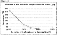
Figure 2 is a graph illustrating the difference in inlet and outlet temperature of the reactor while the weight ratio of methanol to light naphtha was changed from 0% to 100% in the course of the catalytic cracking reaction process under the same conditions as described in Comparative Example 1. -
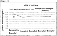
Figure 3 is a graph illustrating the yield of methane of the processes of Examples 1 ∼ 4 and Comparative Examples 1 and 2 of the present invention. -
Figure 4 is a graph illustrating the yield of light olefins of the processes of Examples 1 ∼ 4 and Comparative Examples 1 and 2 of the present invention. -
Figure 5 is a graph illustrating the changes of the reactor temperature after the processes of Examples 1 ∼ 4 and Comparative Examples 1 and 2 of the present invention. - Hereinafter, the present invention is described in detail.
- The present invention provides a naphtha and methanol mixed catalytic cracking reaction process involving a simultaneous cracking reaction of naphtha and methanol using a circulating fluidized-bed reactor comprising a reactor, a stripper, and a regenerator, wherein the naphtha is supplied from the bottom part of the reactor at a position between 0% ∼ 5% of the total length of the reactor, and the methanol is supplied from the bottom part of the reactor at a position between 10% ∼ 80% of the total length of the reactor.
- At this time, an example of the circulating fluidized-bed reactor performing the naphtha and methanol mixed catalytic cracking reaction process is presented in
Figure 1 . - Hereinafter, with referring to the schematic diagram of
Figure 1 illustrating an example of the circulating fluidized-bed reactor, the cracking reaction process of the present invention is described in more detail. - The conventional techniques and methods have been focused only on the realization of heat neutralization in order to increase energy efficiency in the simultaneous cracking reaction of naphtha and methanol that are different in reaction speed and reaction heat. However, this proposed idea only for heat neutralization is not enough to obtain light olefins with high yield after the simultaneous introduction of the two reactants, and thus it is required to regulate the contact time precisely with considering the reaction speed of each reactant.
- To overcome the said problem, the present invention used a circulating fluidized-bed reactor and regulated the introduction positions of hydrocarbon and methanol in order to control the contact timing between both naphtha and methanol and a catalyst more precisely.
- If the contact time between a reactant and a catalyst is short in the course of cracking reaction of naphtha and methanol, the cracking reaction would not be going smooth and the intermediate products, light olefins such as ethylene and propylene, would not be fully cracked. On the other hand, if the contact time between the two is too long, side reaction would be induced, resulting in the large volume of unwanted by-products. Therefore, it is important to regulate the contact time between a reactant and a catalyst.
- In particular, the cracking speed of methanol is at least 10 times faster than that of naphtha, the hydrocarbon. If the two reactants are introduced at the same time, methanol would stay longer so that the production of light saturated hydrocarbons such as methane, ethane, and propane and the production of BTX would increase. To solve the problem, it is required to make the stay of methanol short, for which the introduction positions of naphtha and methanol are preferably adjusted.
- The circulating fluidized-bed reactor (100) used in the catalytic cracking reaction process of the invention preferably comprises a reactor (10), a stripper (20), and a regenerator (30).
- The reactor (10) herein can be preferably a riser. The riser is preferably 5 - 15 m in length and 1/4 ∼ 1 inch in diameter, but not always limited thereto. The reactor (10) can also include tubes through which naphtha and methanol are supplied. Since the introduction positions of naphtha and methanol in the catalytic cracking reaction process of the invention are varied, so that the tubes for the supply of naphtha and methanol are separately formed.
- The stripper (20) can contain a cylinder (21) to discharge the product gas generated from naphtha and methanol. The regenerator (30) is located below the stripper, and the reactor can additionally include a valve (22) for separating the stripper and the regenerator and regulating the circulation flow of the catalyst and the fuel gas.
- The regenerator (30) can contain a cylinder (31) to discharge fuel gas (naphtha and methanol). The regenerator is filled with a catalyst and is equipped with a tube at the lower part, through which air is supplied. The reactor (10) is preferably connected to the lower part of the regenerator. The regenerator can also include a valve (32) to divide the regenerator and the reactor and to regulate the circulation of the catalyst and fuel gas.
- In the catalytic cracking reaction process of the present invention, a circulating fluidized-bed reactor is used to crack naphtha and methanol simultaneously. At this time, naphtha is supplied to the lower part of the reactor and methanol is supplied to a different position apart from the lower part. The introduction position of methanol can vary from the reaction temperature, the volume of a circulating catalyst, and the introduction amount of the reactant, and can be preferably at the position between 10% ∼ 80% by the total length of the reactor from the lower part. The different introduction positions can achieve heat neutralization and can increase the yield of light olefins best.
- To regulate the contact time of naphtha and methanol with a catalyst more precisely, naphtha is supplied from the lower part of the reactor at a position between 0% ∼ 5% of the total length of the reactor. In the meantime, methanol is supplied from the lower part of the reactor at a position between 10% ∼ 80% of the total length of the reactor. More preferably, methanol is supplied from the lower part of the reactor at a position between 15% ∼ 45% of the total length of the reactor.
- At this time, the naphtha used as the reactant can contain C4 ∼ C12 saturated hydrocarbon or unsaturated hydrocarbon, which is exemplified by full-range naphtha, light naphtha, raffinate oil, and a mixture thereof. Unlike the pyrolysis process using saturated hydrocarbon only, hydrocarbon containing olefins can be used as the reactant in the circulating fluidized-bed catalytic cracking process.
- In the meantime, the methanol used as the reactant herein can be not only anhydrous methanol but also methanol containing moisture up to 20%.
- In the circulating fluidized-bed reactor (100), a catalyst is circulated. At this time, the catalyst is preferably a zeolite catalyst. More precisely, the catalyst can be a molded spherical or oval catalyst of 20 ∼ 200 µm in diameter comprising ZSM-5 or SAPO-34 as a catalyst component, a binder and a matrix, but not always limited thereto.
- Further, the supply ratio of naphtha and methanol is preferably 1 (weight part) : 0.2 ∼ 1.4 (weight part). If the supply ratio of naphtha and methanol is less than 1 : 0.2, the calorific value due to the exothermic reaction of methanol would be reduced so that the energy consumption for maintaining the reaction temperature would be increased. On the other hand, if the supply ratio of naphtha and methanol is more than 1 : 1.4, the amount of by-products such as CO and CH4 would be increased.
- It is also preferred to induce reaction of naphtha and methanol at the temperature of 600 ∼ 700 °C at the space velocity of 5 h-1 ∼ 30 h-1. The retention time of naphtha and methanol in the reactor is preferably 1 ∼ 5 seconds. If the reaction temperature of naphtha and methanol is lower than 600 °C, the conversion rate would be lowered, indicating that the yield of a target product would be dropped quickly. If the temperature is higher than 700 °C, most of the reactants would be converted into coke, resulting in the decrease of the yield of a target product. If the space velocity of the reaction of naphtha and methanol is less than 5 h-1, the production of coke is accelerated due to the fast conversion of methanol. On the other hand, if the space velocity is higher than 30 h-1, the conversion rate of naphtha would be significantly reduced.
- The present invention also provides light olefins produced by the naphtha and methanol mixed catalytic cracking reaction process involving a simultaneous cracking reaction of naphtha and methanol using a circulating fluidized-bed reactor comprising a reactor, a stripper, and a regenerator, wherein the naphtha is supplied from the bottom part of the reactor at a position between 0% ∼ 5% of the total length of the reactor, and the methanol is supplied from the bottom part of the reactor at a position between 10% ∼ 80% of the total length of the reactor.
- The catalytic cracking reaction process provided by the invention uses the circulating fluidized-bed reactor and can crack naphtha and methanol simultaneously by having different introduction positions for the naphtha and methanol in the reactor, which is advantageous for heat neutralization, so that energy consumption can be minimized and also the yield of light olefins can be improved by suppressing the production of light saturated hydrocarbons such as methane, ethane and propane. Thus, the prepared light olefins thereby can be used economically.
- In addition, the present invention provides a method for increasing the yield of light olefins via the naphtha and methanol mixed catalytic cracking reaction process involving a simultaneous cracking reaction of naphtha and methanol using a circulating fluidized-bed reactor comprising a reactor, a stripper, and a regenerator, wherein the naphtha is supplied from the bottom part of the reactor at a position between 0% ∼ 5% of the total length of the reactor, and the methanol is supplied from the bottom part of the reactor at a position between 10% ∼ 80% of the total length of the reactor.
- Hereinafter, the method to increase the yield of light olefins of the present invention is described in more detail.
- The conventional techniques and methods have been focused only on the realization of heat neutralization in order to increase energy efficiency in the simultaneous cracking reaction of naphtha and methanol that are different in reaction speed and reaction heat. However, this proposed idea only for heat neutralization is not enough to obtain light olefins with high yield after the simultaneous introduction of the two reactants, and thus it is required to regulate the contact time precisely with considering the reaction speed of each reactant.
- To overcome the said problem, the present invention used a circulating fluidized-bed reactor and regulated the introduction positions of hydrocarbon and methanol in order to control the contact time between both naphtha and methanol and a catalyst more precisely.
- If the contact time between a reactant and a catalyst is short in the course of cracking reaction of naphtha and methanol, the cracking reaction would not be going smooth and the intermediate products, light olefins such as ethylene and propylene, would not be fully cracked. On the other hand, if the contact time between the two is too long, side reaction would be induced, resulting in the large volume of unwanted by-products. Therefore, it is important to regulate the contact time between a reactant and a catalyst.
- In particular, the cracking speed of methanol is at least 10 times faster than that of naphtha, the hydrocarbon. If the two reactants are introduced at the same time, methanol would stay longer so that the production of light saturated hydrocarbons such as methane, ethane, and propane and the production of BTX would increase. To solve the problem, it is required to make the stay of methanol short, for which the introduction positions of naphtha and methanol are preferably adjusted.
- The circulating fluidized-bed reactor (100) used in this invention to increase the yield of light olefins preferably contains a reactor (10), a stripper (20), and a regenerator (30).
- The reactor (10) herein can be preferably a riser. The riser is preferably 5 - 15 m in length and 1/4 ∼ 1 inch in diameter, but not always limited thereto. The reactor (10) can also include tubes through which naphtha and methanol are supplied. Since the introduction positions of naphtha and methanol in the catalytic cracking reaction process of the invention are varied, so that the tubes for the supply of naphtha and methanol are separately formed.
- The stripper (20) can contain a cylinder (21) to discharge the product gas generated from naphtha and methanol. The regenerator (30) is located below the stripper, and the reactor can additionally include a valve (22) for separating the stripper and the regenerator and regulating the circulation flow of the catalyst and the fuel gas.
- The regenerator (30) can contain a cylinder (31) to discharge fuel gas (naphtha and methanol). The regenerator is filled with a catalyst and is equipped with a tube at the lower part, through which air is supplied. The reactor (10) is preferably connected to the lower part of the regenerator. The regenerator can also include a valve (32) to divide the regenerator and the reactor and to regulate the circulation of the catalyst and fuel gas.
- In the method to increase the yield of light olefins of the present invention, a circulating fluidized-bed reactor is used to crack naphtha and methanol simultaneously. At this time, naphtha is supplied to the lower part of the reactor and methanol is supplied to a different position apart from the lower part. The introduction position of methanol can vary from the reaction temperature, the volume of a circulating catalyst, and the introduction amount of the reactant, and can be preferably at the position between 10% ∼ 80% by the total length of the reactor from the lower part. The different introduction positions can achieve heat neutralization and can increase the yield of light olefins best.
- To regulate the contact time of naphtha and methanol with a catalyst more precisely, naphtha is supplied from the lower part of the reactor at a position between 0% ∼ 5% of the total length of the reactor. In the meantime, methanol is supplied from the lower part of the reactor at a position between 10% ∼ 80% of the total length of the reactor. More preferably, methanol is supplied from the lower part of the reactor at a position between 15% ∼ 45% of the total length of the reactor.
- At this time, the naphtha used as the reactant can contain C4 ∼ C12 saturated hydrocarbon or unsaturated hydrocarbon, which is exemplified by full-range naphtha, light naphtha, raffinate oil, and a mixture thereof. Unlike the pyrolysis process using saturated hydrocarbon only, hydrocarbon containing olefins can be used as the reactant in the circulating fluidized-bed catalytic cracking process.
- In the meantime, the methanol used as the reactant herein can be not only anhydrous methanol but also methanol containing moisture up to 20%.
- In the circulating fluidized-bed reactor (100), a catalyst is circulated. At this time, the catalyst is preferably a zeolite catalyst. More precisely, the catalyst can be a molded spherical or oval catalyst of 20 ∼ 200 µm in diameter comprising ZSM-5 or SAPO-34 as a catalyst component, a binder and a matrix, but not always limited thereto.
- Further, the supply ratio of naphtha and methanol is preferably 1 (weight part) : 0.2 ∼ 1.4 (weight part). If the supply ratio of naphtha and methanol is less than 1 : 0.2, the calorific value due to the exothermic reaction of methanol would be reduced so that the energy consumption for maintaining the reaction temperature would be increased. On the other hand, if the supply ratio of naphtha and methanol is more than 1 : 1.4, the amount of by-products such as CO and CH4 would be increased.
- It is also preferred to induce reaction of naphtha and methanol at the temperature of 600 ∼ 700°C at the space velocity of 5 h-1 ∼ 30 h-1. The retention time of naphtha and methanol in the reactor is preferably 1 ∼ 5 seconds. If the reaction temperature of naphtha and methanol is lower than 600 °C, the conversion rate would be lowered, indicating that the yield of a target product would be dropped quickly. If the temperature is higher than 700 °C, most of the reactants would be converted into coke, resulting in the decrease of the yield of a target product. If the space velocity of the reaction of naphtha and methanol is less than 5 h-1, the production of coke is accelerated due to the fast conversion of methanol. On the other hand, if the space velocity is higher than 30 h-1, the conversion rate of naphtha would be significantly reduced.
- Practical and presently preferred embodiments of the present invention are illustrative as shown in the following Examples.
- However, it will be appreciated that those skilled in the art, on consideration of this disclosure, may make modifications and improvements within the spirit and scope of the present invention.
- To perform the catalytic cracking reaction process according to the present invention, a circulating fluidized-bed reactor was prepared as shown in the schematic diagram of
Figure 1 . - The said circulating fluidized-bed reactor is composed of a reactor, a stripper, and a regenerator, and is 7 m in length and 1/2 inch in diameter.
- At this time, ACO-100 comprising HZSM-5 at 40 weight% which is used for ACO™ process is used as a catalyst. To investigate the characteristics of E-cat, steaming was performed at 700°C for 24 hours in 100% steam atmosphere, and then 3 kg of the catalyst was loaded in the regenerator.
- To introduce the two reactants, naphtha and methanol (MeOH), at different positions, methanol introduction nozzles were equipped at different positions (positions of 20%, 40%, 60%, and 80% of the total length of the rector from the lower part). The naphtha introduced in the reactor was light naphtha. The weight ratio of light naphtha and methanol was 1 : 0.25.
- Naphtha introduction position was located at the lower part of the reactor and methanol introduction positions were set differently at the positions of 20%, 40%, 60%, and 80% of the total length of the reactor from the lower part of the reactor.
- The reactor inlet temperature was 700°C and the Cat/Oil ratio was 25.
- The circulating fluidized-bed reactor used in Examples 1 ∼ 4 was used herein.
- At this time, the naphtha introduced in the reactor was light naphtha, and the weight ratio of light naphtha and methanol was 1 : 0.25.
- Naphtha and methanol were supplied into the lower part of the reactor.
- The reactor inlet temperature was 700°C and the Cat/Oil ratio was 25.
- The circulating fluidized-bed reactor used in Examples 1 ∼ 4 was used herein.
- At this time, the naphtha introduced in the reactor was light naphtha, and methanol was not supplied.
- Naphtha was supplied into the lower part of the reactor.
- The reactor inlet temperature was 700°C and the Cat/Oil ratio was 35.
- To investigate the heat neutralization in the course of naphtha and methanol simultaneous cracking reaction according to the catalytic cracking reaction process of the invention, the catalytic cracking reaction process was performed by the same manners as described in Comparative Example 1. Methanol was supplied with changing the volume from 0 weight% to 100 weight% by the weight of light naphtha. The difference in the temperature between the reactor inlet and outlet was observed. The results are shown in
Figure 2 . - As shown in
Figure 2 , it was confirmed that when the weight ratio of methanol to light naphtha was about 60 weight%, heat neutralization with zero energy consumption was occurred. Therefore, the catalytic cracking process of the invention could make it possible to ensure the heat neutralization and to crack naphtha and methanol simultaneously. - To investigate the changes according to the different methanol introduction positions in the catalytic cracking reaction process of the present invention, the processes of Examples 1 ∼ 4 and Comparative Examples 1 ∼ 2 were performed, during which the yield of methanol, the yield of light olefins, and the temperature of the reactor were analyzed. The results are shown in
Figures 3 ∼ 5 . - As shown in
Figures 3 ∼ 5 , in Comparative Example 2 wherein light naphtha alone was cracked, the temperature of the reactor (AT) was 700°C and the yield of light olefins was 33.5 weight%. In the meantime, the yield of methanol was approximately 10 weight%. - In Comparative Example 1 wherein naphtha (hydrocarbon) and methanol were cracked simultaneously, the temperature of the reactor was reduced but the yield of light olefins was increased. The yield of methanol was significantly increased up to 13 weight%.
- In Examples 1 ∼ 4 wherein the methanol introduction positions were regulated in the course of the catalytic cracking reaction process of the invention, the yield of methanol was hardly increased and the temperature of the reactor was maintained equally.
- In particular, the yield of light olefins (ethylene + propylene) was approximately 40 weight% at maximum, which was increased by 15 weight% compared with that of the case wherein naphtha and methanol were supplied simultaneously into the lower part of the reactor.
- Those skilled in the art will appreciate that the conceptions and specific embodiments disclosed in the foregoing description may be readily utilized as a basis for modifying or designing other embodiments for carrying out the same purposes of the present invention. Those skilled in the art will also appreciate that such equivalent embodiments do not depart from the spirit and scope of the invention as set forth in the appended Claims.
Claims (10)
- A naphtha and methanol mixed catalytic cracking reaction process involving a simultaneous cracking reaction of naphtha and methanol using a circulating fluidized-bed reactor comprising a reactor, a stripper, and a regenerator, wherein the naphtha is supplied from the bottom part of the reactor at a position between 0% ∼ 5% of the total length of the reactor, and the methanol is supplied from the bottom part of the reactor at a position between 10% ∼ 80% of the total length of the reactor.
- The naphtha and methanol mixed catalytic cracking reaction process according to claim 1, wherein the methanol is supplied into the lower part of the reactor at a position between 15% ∼ 45% of the total length of the reactor.
- The naphtha and methanol mixed catalytic cracking reaction process according to claim 1, wherein the naphtha contains C4 ∼ C12 saturated hydrocarbon or unsaturated hydrocarbon.
- The naphtha and methanol mixed catalytic cracking reaction process according to claim 1, wherein the naphtha is one or more materials selected from the group consisting of full-range naphtha, light naphtha, raffinate oil, and a mixture thereof.
- The naphtha and methanol mixed catalytic cracking reaction process according to claim 1, wherein the catalyst is circulated in the circulating fluidized-bed reactor and at this time the catalyst is a molded spherical or oval catalyst of 20 ∼ 200 µm in diameter comprising ZSM-5 or SAPO-34 as a catalyst component, a binder and a matrix, but not always limited thereto.
- The naphtha and methanol mixed catalytic cracking reaction process according to claim 1, wherein the supply ratio of naphtha and methanol is 1 weight part : 0.2 ∼ 1.4 weight part.
- The naphtha and methanol mixed catalytic cracking reaction process according to claim 1, wherein the cracking reaction of naphtha and methanol is performed at the temperature of 600 ∼ 700°C and at the space velocity of 5 h-1 ∼ 30 h-1.
- The naphtha and methanol mixed catalytic cracking reaction process according to claim 1, wherein the retention time of naphtha and methanol in the reactor is 1 ∼ 5 seconds.
- A light olefin produced by the naphtha and methanol mixed catalytic cracking reaction process involving a simultaneous cracking reaction of naphtha and methanol using a circulating fluidized-bed reactor comprising a reactor, a stripper, and a regenerator, wherein the naphtha is supplied from the bottom part of the reactor at a position between 0% ∼ 5% of the total length of the reactor, and the methanol is supplied from the bottom part of the reactor at a position between 10% ∼ 80% of the total length of the reactor.
- A method for increasing the yield of light olefins via the naphtha and methanol mixed catalytic cracking reaction process involving a simultaneous cracking reaction of naphtha and methanol using a circulating fluidized-bed reactor comprising a reactor, a stripper, and a regenerator, wherein the naphtha is supplied from the bottom part of the reactor at a position between 0% ∼ 5% of the total length of the reactor, and the methanol is supplied from the bottom part of the reactor at a position between 10% ∼ 80% of the total length of the reactor.
Applications Claiming Priority (3)
| Application Number | Priority Date | Filing Date | Title |
|---|---|---|---|
| KR20140098863 | 2014-08-01 | ||
| KR1020150106710A KR101803406B1 (en) | 2014-08-01 | 2015-07-28 | Process for catalytic cracking reaction of naphtha and methanol mixture |
| PCT/KR2015/007989 WO2016018097A1 (en) | 2014-08-01 | 2015-07-30 | Naphtha and methanol mixed catalytic cracking reaction process |
Publications (3)
| Publication Number | Publication Date |
|---|---|
| EP3176242A1 true EP3176242A1 (en) | 2017-06-07 |
| EP3176242A4 EP3176242A4 (en) | 2018-02-21 |
| EP3176242B1 EP3176242B1 (en) | 2019-04-03 |
Family
ID=55357272
Family Applications (1)
| Application Number | Title | Priority Date | Filing Date |
|---|---|---|---|
| EP15826774.0A Active EP3176242B1 (en) | 2014-08-01 | 2015-07-30 | Naphtha and methanol mixed catalytic cracking reaction process |
Country Status (5)
| Country | Link |
|---|---|
| US (1) | US10131850B2 (en) |
| EP (1) | EP3176242B1 (en) |
| JP (1) | JP6343400B2 (en) |
| KR (1) | KR101803406B1 (en) |
| CN (1) | CN106715656A (en) |
Families Citing this family (7)
| Publication number | Priority date | Publication date | Assignee | Title |
|---|---|---|---|---|
| CN114286720B (en) | 2019-08-05 | 2023-11-07 | 沙特基础工业全球技术公司 | Baffled turbulent/fast fluidized bed reactor for maximizing low carbon olefin yield |
| KR102573887B1 (en) * | 2021-09-10 | 2023-09-04 | 한국화학연구원 | Circulating fluidized bed reactor using electric heating furnace |
| EP4610244A1 (en) | 2022-10-25 | 2025-09-03 | Korea Research Institute of Chemical Technology | Method for preparing raw material for plastics by using steel by-product gas |
| KR102957482B1 (en) | 2022-10-25 | 2026-04-27 | 한국화학연구원 | A method for preparing plastic monomers by using steel by-product gas |
| JP7846784B2 (en) * | 2022-11-24 | 2026-04-15 | 中国神華煤製油化工有限公司 | Apparatus and method for preparing aromatic hydrocarbons by coupling naphtha and methanol. |
| KR20250055823A (en) * | 2023-10-18 | 2025-04-25 | 한국화학연구원 | Method for producing light olefins from waste plastics |
| KR20250139496A (en) * | 2024-03-15 | 2025-09-23 | 서울시립대학교 산학협력단 | Apparatus for the production of light olefin from waste plastic and method for producing light olefin using the same |
Family Cites Families (11)
| Publication number | Priority date | Publication date | Assignee | Title |
|---|---|---|---|---|
| US6797851B2 (en) * | 2001-08-30 | 2004-09-28 | Exxonmobil Chemical Patents Inc. | Two catalyst process for making olefin |
| EP1508555A1 (en) | 2003-08-19 | 2005-02-23 | Total Petrochemicals Research Feluy | Production of olefins |
| KR100632563B1 (en) | 2004-09-10 | 2006-10-09 | 에스케이 주식회사 | Solid acid catalyst for catalytic cracking and process for selectively preparing light olefins from full range naphtha |
| KR100651329B1 (en) | 2005-10-07 | 2006-11-30 | 에스케이 주식회사 | Process for preparing light olefins from hydrocarbon raw materials |
| CN1986505B (en) | 2005-12-23 | 2010-04-14 | 中国石油化工股份有限公司 | A catalytic conversion method for increasing production of low-carbon olefins |
| CN101130469B (en) | 2006-08-23 | 2011-04-13 | 中国科学院大连化学物理研究所 | Method for recovering reactivation heat in process of preparing low carbon olefinic hydrocarbon with methanol |
| CN102531821B (en) | 2010-12-28 | 2015-03-25 | 中国科学院大连化学物理研究所 | Method for catalyzing catalytic cracking reaction of methanol coupled with naphtha using modified ZSM-5 molecular sieve based catalyst |
| CN102875285B (en) * | 2011-07-12 | 2015-12-09 | 中国石油化工股份有限公司 | Methyl alcohol and light naphthar are catalytically conveted to the method for low-carbon alkene |
| CN102875304B (en) | 2011-07-12 | 2015-02-11 | 中国石油化工股份有限公司 | Method for preparing low carbon olefins from methanol and naphtha |
| CN102875299A (en) * | 2011-07-12 | 2013-01-16 | 中国石油化工股份有限公司 | Method for producing low-carbon olefins by using methanol and naphtha |
| EP2814913A1 (en) * | 2012-02-14 | 2014-12-24 | Reliance Industries Limited | A process for catalytic conversion of low value hydrocarbon streams to light olefins |
-
2015
- 2015-07-28 KR KR1020150106710A patent/KR101803406B1/en active Active
- 2015-07-30 CN CN201580052123.2A patent/CN106715656A/en active Pending
- 2015-07-30 US US15/501,006 patent/US10131850B2/en active Active
- 2015-07-30 JP JP2017526029A patent/JP6343400B2/en active Active
- 2015-07-30 EP EP15826774.0A patent/EP3176242B1/en active Active
Also Published As
| Publication number | Publication date |
|---|---|
| JP6343400B2 (en) | 2018-06-13 |
| EP3176242B1 (en) | 2019-04-03 |
| EP3176242A4 (en) | 2018-02-21 |
| KR101803406B1 (en) | 2017-12-01 |
| CN106715656A (en) | 2017-05-24 |
| KR20160016637A (en) | 2016-02-15 |
| US20170253811A1 (en) | 2017-09-07 |
| JP2017526802A (en) | 2017-09-14 |
| US10131850B2 (en) | 2018-11-20 |
Similar Documents
| Publication | Publication Date | Title |
|---|---|---|
| EP3176242B1 (en) | Naphtha and methanol mixed catalytic cracking reaction process | |
| AU2010318050B2 (en) | Process and integrated system for the preparation of a lower olefin product | |
| Zhang et al. | Catalytic conversion of biomass pyrolysis-derived compounds with chemical liquid deposition (CLD) modified ZSM-5 | |
| US7112307B2 (en) | Riser reactor system for hydrocarbon cracking | |
| US20110112345A1 (en) | Process for the preparation of a lower olefin product | |
| RU2550354C1 (en) | Method for producing aromatic hydrocarbon concentrate of light aliphatic hydrocarbons and device for implementing it | |
| CN101898927B (en) | Method for preparing light olefins from alcohols | |
| CN109280561A (en) | A kind of method of naphtha or the low-temperature catalyzed reaction propylene co-production aromatic hydrocarbons processed of lighter hydrocarbons | |
| CN108276238B (en) | Method for preparing low-carbon olefin by Fischer-Tropsch synthesis light oil and methanol co-catalytic cracking | |
| CN102942435B (en) | Reaction technology using moving bed technique to convert methanol into propylene | |
| AU2007291786A1 (en) | A process for recovering regenerated heat during the production of lower olefins from methanol | |
| EP3040324A1 (en) | A Process for Converting Oxygenates to Olefins and Aromatics | |
| CN104045499B (en) | A kind of utilize the method for ethylene production aromatic hydrocarbons in oil refinery dry gas | |
| CN103121891B (en) | Method for producing low-carbon olefin | |
| CN102245542A (en) | Process for preparing products containing C3H6 and C2H4 | |
| US20170088482A1 (en) | Process and plant for producing olefins | |
| CN102464522A (en) | Production method of low-carbon olefin | |
| WO2016109370A1 (en) | An oxygenate conversion process | |
| CN103694077A (en) | Reaction technology for production of propylene and coproduction of high-octane value gasoline components | |
| CN107721791A (en) | The preparation system and preparation method of a kind of preparing propylene from methanol | |
| CN108325477A (en) | A kind of tandem moving bed reaction system and methods for using them for oxygenate conversion | |
| CN111073695B (en) | Fischer-Tropsch synthesis naphtha modification method | |
| CN108314601B (en) | Cascade moving bed reaction system and method for converting oxygen-containing compound | |
| WO2016018097A1 (en) | Naphtha and methanol mixed catalytic cracking reaction process | |
| WO2014207134A1 (en) | An olefin cracking catalyst |
Legal Events
| Date | Code | Title | Description |
|---|---|---|---|
| STAA | Information on the status of an ep patent application or granted ep patent |
Free format text: STATUS: THE INTERNATIONAL PUBLICATION HAS BEEN MADE |
|
| 17P | Request for examination filed |
Effective date: 20170301 |
|
| AK | Designated contracting states |
Kind code of ref document: A1 Designated state(s): AL AT BE BG CH CY CZ DE DK EE ES FI FR GB GR HR HU IE IS IT LI LT LU LV MC MK MT NL NO PL PT RO RS SE SI SK SM TR |
|
| AX | Request for extension of the european patent |
Extension state: BA ME |
|
| PUAI | Public reference made under article 153(3) epc to a published international application that has entered the european phase |
Free format text: ORIGINAL CODE: 0009012 |
|
| STAA | Information on the status of an ep patent application or granted ep patent |
Free format text: STATUS: REQUEST FOR EXAMINATION WAS MADE |
|
| DAV | Request for validation of the european patent (deleted) | ||
| DAX | Request for extension of the european patent (deleted) | ||
| REG | Reference to a national code |
Ref country code: DE Ref legal event code: R079 Ref document number: 602015027769 Country of ref document: DE Free format text: PREVIOUS MAIN CLASS: C10G0011180000 Ipc: C10G0003000000 |
|
| A4 | Supplementary search report drawn up and despatched |
Effective date: 20180123 |
|
| RIC1 | Information provided on ipc code assigned before grant |
Ipc: C10G 3/00 20060101AFI20180117BHEP Ipc: C10G 11/18 20060101ALI20180117BHEP |
|
| GRAP | Despatch of communication of intention to grant a patent |
Free format text: ORIGINAL CODE: EPIDOSNIGR1 |
|
| STAA | Information on the status of an ep patent application or granted ep patent |
Free format text: STATUS: GRANT OF PATENT IS INTENDED |
|
| INTG | Intention to grant announced |
Effective date: 20181114 |
|
| GRAS | Grant fee paid |
Free format text: ORIGINAL CODE: EPIDOSNIGR3 |
|
| GRAA | (expected) grant |
Free format text: ORIGINAL CODE: 0009210 |
|
| STAA | Information on the status of an ep patent application or granted ep patent |
Free format text: STATUS: THE PATENT HAS BEEN GRANTED |
|
| AK | Designated contracting states |
Kind code of ref document: B1 Designated state(s): AL AT BE BG CH CY CZ DE DK EE ES FI FR GB GR HR HU IE IS IT LI LT LU LV MC MK MT NL NO PL PT RO RS SE SI SK SM TR |
|
| REG | Reference to a national code |
Ref country code: GB Ref legal event code: FG4D |
|
| REG | Reference to a national code |
Ref country code: CH Ref legal event code: EP Ref country code: AT Ref legal event code: REF Ref document number: 1115707 Country of ref document: AT Kind code of ref document: T Effective date: 20190415 |
|
| REG | Reference to a national code |
Ref country code: DE Ref legal event code: R096 Ref document number: 602015027769 Country of ref document: DE |
|
| REG | Reference to a national code |
Ref country code: IE Ref legal event code: FG4D |
|
| REG | Reference to a national code |
Ref country code: NL Ref legal event code: FP |
|
| REG | Reference to a national code |
Ref country code: LT Ref legal event code: MG4D |
|
| REG | Reference to a national code |
Ref country code: AT Ref legal event code: MK05 Ref document number: 1115707 Country of ref document: AT Kind code of ref document: T Effective date: 20190403 |
|
| PG25 | Lapsed in a contracting state [announced via postgrant information from national office to epo] |
Ref country code: SE Free format text: LAPSE BECAUSE OF FAILURE TO SUBMIT A TRANSLATION OF THE DESCRIPTION OR TO PAY THE FEE WITHIN THE PRESCRIBED TIME-LIMIT Effective date: 20190403 Ref country code: LT Free format text: LAPSE BECAUSE OF FAILURE TO SUBMIT A TRANSLATION OF THE DESCRIPTION OR TO PAY THE FEE WITHIN THE PRESCRIBED TIME-LIMIT Effective date: 20190403 Ref country code: AL Free format text: LAPSE BECAUSE OF FAILURE TO SUBMIT A TRANSLATION OF THE DESCRIPTION OR TO PAY THE FEE WITHIN THE PRESCRIBED TIME-LIMIT Effective date: 20190403 Ref country code: PT Free format text: LAPSE BECAUSE OF FAILURE TO SUBMIT A TRANSLATION OF THE DESCRIPTION OR TO PAY THE FEE WITHIN THE PRESCRIBED TIME-LIMIT Effective date: 20190803 Ref country code: NO Free format text: LAPSE BECAUSE OF FAILURE TO SUBMIT A TRANSLATION OF THE DESCRIPTION OR TO PAY THE FEE WITHIN THE PRESCRIBED TIME-LIMIT Effective date: 20190703 Ref country code: HR Free format text: LAPSE BECAUSE OF FAILURE TO SUBMIT A TRANSLATION OF THE DESCRIPTION OR TO PAY THE FEE WITHIN THE PRESCRIBED TIME-LIMIT Effective date: 20190403 Ref country code: FI Free format text: LAPSE BECAUSE OF FAILURE TO SUBMIT A TRANSLATION OF THE DESCRIPTION OR TO PAY THE FEE WITHIN THE PRESCRIBED TIME-LIMIT Effective date: 20190403 Ref country code: CZ Free format text: LAPSE BECAUSE OF FAILURE TO SUBMIT A TRANSLATION OF THE DESCRIPTION OR TO PAY THE FEE WITHIN THE PRESCRIBED TIME-LIMIT Effective date: 20190403 |
|
| PG25 | Lapsed in a contracting state [announced via postgrant information from national office to epo] |
Ref country code: GR Free format text: LAPSE BECAUSE OF FAILURE TO SUBMIT A TRANSLATION OF THE DESCRIPTION OR TO PAY THE FEE WITHIN THE PRESCRIBED TIME-LIMIT Effective date: 20190704 Ref country code: BG Free format text: LAPSE BECAUSE OF FAILURE TO SUBMIT A TRANSLATION OF THE DESCRIPTION OR TO PAY THE FEE WITHIN THE PRESCRIBED TIME-LIMIT Effective date: 20190703 Ref country code: PL Free format text: LAPSE BECAUSE OF FAILURE TO SUBMIT A TRANSLATION OF THE DESCRIPTION OR TO PAY THE FEE WITHIN THE PRESCRIBED TIME-LIMIT Effective date: 20190403 Ref country code: RS Free format text: LAPSE BECAUSE OF FAILURE TO SUBMIT A TRANSLATION OF THE DESCRIPTION OR TO PAY THE FEE WITHIN THE PRESCRIBED TIME-LIMIT Effective date: 20190403 Ref country code: LV Free format text: LAPSE BECAUSE OF FAILURE TO SUBMIT A TRANSLATION OF THE DESCRIPTION OR TO PAY THE FEE WITHIN THE PRESCRIBED TIME-LIMIT Effective date: 20190403 |
|
| PG25 | Lapsed in a contracting state [announced via postgrant information from national office to epo] |
Ref country code: IS Free format text: LAPSE BECAUSE OF FAILURE TO SUBMIT A TRANSLATION OF THE DESCRIPTION OR TO PAY THE FEE WITHIN THE PRESCRIBED TIME-LIMIT Effective date: 20190803 Ref country code: AT Free format text: LAPSE BECAUSE OF FAILURE TO SUBMIT A TRANSLATION OF THE DESCRIPTION OR TO PAY THE FEE WITHIN THE PRESCRIBED TIME-LIMIT Effective date: 20190403 |
|
| REG | Reference to a national code |
Ref country code: DE Ref legal event code: R097 Ref document number: 602015027769 Country of ref document: DE |
|
| PG25 | Lapsed in a contracting state [announced via postgrant information from national office to epo] |
Ref country code: EE Free format text: LAPSE BECAUSE OF FAILURE TO SUBMIT A TRANSLATION OF THE DESCRIPTION OR TO PAY THE FEE WITHIN THE PRESCRIBED TIME-LIMIT Effective date: 20190403 Ref country code: DK Free format text: LAPSE BECAUSE OF FAILURE TO SUBMIT A TRANSLATION OF THE DESCRIPTION OR TO PAY THE FEE WITHIN THE PRESCRIBED TIME-LIMIT Effective date: 20190403 Ref country code: SK Free format text: LAPSE BECAUSE OF FAILURE TO SUBMIT A TRANSLATION OF THE DESCRIPTION OR TO PAY THE FEE WITHIN THE PRESCRIBED TIME-LIMIT Effective date: 20190403 Ref country code: RO Free format text: LAPSE BECAUSE OF FAILURE TO SUBMIT A TRANSLATION OF THE DESCRIPTION OR TO PAY THE FEE WITHIN THE PRESCRIBED TIME-LIMIT Effective date: 20190403 |
|
| PLBE | No opposition filed within time limit |
Free format text: ORIGINAL CODE: 0009261 |
|
| STAA | Information on the status of an ep patent application or granted ep patent |
Free format text: STATUS: NO OPPOSITION FILED WITHIN TIME LIMIT |
|
| PG25 | Lapsed in a contracting state [announced via postgrant information from national office to epo] |
Ref country code: MC Free format text: LAPSE BECAUSE OF FAILURE TO SUBMIT A TRANSLATION OF THE DESCRIPTION OR TO PAY THE FEE WITHIN THE PRESCRIBED TIME-LIMIT Effective date: 20190403 Ref country code: IT Free format text: LAPSE BECAUSE OF FAILURE TO SUBMIT A TRANSLATION OF THE DESCRIPTION OR TO PAY THE FEE WITHIN THE PRESCRIBED TIME-LIMIT Effective date: 20190403 Ref country code: SM Free format text: LAPSE BECAUSE OF FAILURE TO SUBMIT A TRANSLATION OF THE DESCRIPTION OR TO PAY THE FEE WITHIN THE PRESCRIBED TIME-LIMIT Effective date: 20190403 |
|
| REG | Reference to a national code |
Ref country code: CH Ref legal event code: PL |
|
| 26N | No opposition filed |
Effective date: 20200106 |
|
| GBPC | Gb: european patent ceased through non-payment of renewal fee |
Effective date: 20190730 |
|
| PG25 | Lapsed in a contracting state [announced via postgrant information from national office to epo] |
Ref country code: TR Free format text: LAPSE BECAUSE OF FAILURE TO SUBMIT A TRANSLATION OF THE DESCRIPTION OR TO PAY THE FEE WITHIN THE PRESCRIBED TIME-LIMIT Effective date: 20190403 |
|
| REG | Reference to a national code |
Ref country code: BE Ref legal event code: MM Effective date: 20190731 |
|
| PG25 | Lapsed in a contracting state [announced via postgrant information from national office to epo] |
Ref country code: GB Free format text: LAPSE BECAUSE OF NON-PAYMENT OF DUE FEES Effective date: 20190730 |
|
| PG25 | Lapsed in a contracting state [announced via postgrant information from national office to epo] |
Ref country code: LI Free format text: LAPSE BECAUSE OF NON-PAYMENT OF DUE FEES Effective date: 20190731 Ref country code: LU Free format text: LAPSE BECAUSE OF NON-PAYMENT OF DUE FEES Effective date: 20190730 Ref country code: SI Free format text: LAPSE BECAUSE OF FAILURE TO SUBMIT A TRANSLATION OF THE DESCRIPTION OR TO PAY THE FEE WITHIN THE PRESCRIBED TIME-LIMIT Effective date: 20190403 Ref country code: CH Free format text: LAPSE BECAUSE OF NON-PAYMENT OF DUE FEES Effective date: 20190731 Ref country code: BE Free format text: LAPSE BECAUSE OF NON-PAYMENT OF DUE FEES Effective date: 20190731 |
|
| PG25 | Lapsed in a contracting state [announced via postgrant information from national office to epo] |
Ref country code: IE Free format text: LAPSE BECAUSE OF NON-PAYMENT OF DUE FEES Effective date: 20190730 |
|
| PG25 | Lapsed in a contracting state [announced via postgrant information from national office to epo] |
Ref country code: ES Free format text: LAPSE BECAUSE OF FAILURE TO SUBMIT A TRANSLATION OF THE DESCRIPTION OR TO PAY THE FEE WITHIN THE PRESCRIBED TIME-LIMIT Effective date: 20190403 |
|
| PG25 | Lapsed in a contracting state [announced via postgrant information from national office to epo] |
Ref country code: CY Free format text: LAPSE BECAUSE OF FAILURE TO SUBMIT A TRANSLATION OF THE DESCRIPTION OR TO PAY THE FEE WITHIN THE PRESCRIBED TIME-LIMIT Effective date: 20190403 |
|
| PG25 | Lapsed in a contracting state [announced via postgrant information from national office to epo] |
Ref country code: HU Free format text: LAPSE BECAUSE OF FAILURE TO SUBMIT A TRANSLATION OF THE DESCRIPTION OR TO PAY THE FEE WITHIN THE PRESCRIBED TIME-LIMIT; INVALID AB INITIO Effective date: 20150730 Ref country code: MT Free format text: LAPSE BECAUSE OF FAILURE TO SUBMIT A TRANSLATION OF THE DESCRIPTION OR TO PAY THE FEE WITHIN THE PRESCRIBED TIME-LIMIT Effective date: 20190403 |
|
| PG25 | Lapsed in a contracting state [announced via postgrant information from national office to epo] |
Ref country code: MK Free format text: LAPSE BECAUSE OF FAILURE TO SUBMIT A TRANSLATION OF THE DESCRIPTION OR TO PAY THE FEE WITHIN THE PRESCRIBED TIME-LIMIT Effective date: 20190403 |
|
| P01 | Opt-out of the competence of the unified patent court (upc) registered |
Effective date: 20240208 |
|
| PGFP | Annual fee paid to national office [announced via postgrant information from national office to epo] |
Ref country code: NL Payment date: 20250708 Year of fee payment: 11 |
|
| PGFP | Annual fee paid to national office [announced via postgrant information from national office to epo] |
Ref country code: DE Payment date: 20250707 Year of fee payment: 11 |
|
| PGFP | Annual fee paid to national office [announced via postgrant information from national office to epo] |
Ref country code: FR Payment date: 20250715 Year of fee payment: 11 |