EP3175913A1 - Mechanochemical device for mixing and/or reacting at least one chemical compound to at least one reaction product - Google Patents
Mechanochemical device for mixing and/or reacting at least one chemical compound to at least one reaction product Download PDFInfo
- Publication number
- EP3175913A1 EP3175913A1 EP15197992.9A EP15197992A EP3175913A1 EP 3175913 A1 EP3175913 A1 EP 3175913A1 EP 15197992 A EP15197992 A EP 15197992A EP 3175913 A1 EP3175913 A1 EP 3175913A1
- Authority
- EP
- European Patent Office
- Prior art keywords
- milling
- chamber
- recess volume
- reaction product
- elements
- Prior art date
- Legal status (The legal status is an assumption and is not a legal conclusion. Google has not performed a legal analysis and makes no representation as to the accuracy of the status listed.)
- Withdrawn
Links
- 239000007795 chemical reaction product Substances 0.000 title claims abstract description 16
- 150000001875 compounds Chemical class 0.000 title claims abstract description 12
- 238000003801 milling Methods 0.000 claims abstract description 50
- 238000000227 grinding Methods 0.000 claims abstract description 18
- 239000000463 material Substances 0.000 claims description 11
- 229910000831 Steel Inorganic materials 0.000 claims description 4
- 239000010959 steel Substances 0.000 claims description 4
- 239000002245 particle Substances 0.000 claims description 2
- 239000000523 sample Substances 0.000 abstract description 15
- 238000004458 analytical method Methods 0.000 abstract description 12
- 238000000034 method Methods 0.000 abstract description 10
- 238000006243 chemical reaction Methods 0.000 abstract description 6
- 239000002243 precursor Substances 0.000 abstract description 6
- 230000008569 process Effects 0.000 abstract description 6
- 238000005259 measurement Methods 0.000 abstract description 5
- 238000000498 ball milling Methods 0.000 abstract description 4
- 230000033001 locomotion Effects 0.000 description 8
- 238000010303 mechanochemical reaction Methods 0.000 description 5
- 238000013461 design Methods 0.000 description 4
- 239000000843 powder Substances 0.000 description 4
- 238000011065 in-situ storage Methods 0.000 description 3
- 230000005540 biological transmission Effects 0.000 description 2
- 230000008571 general function Effects 0.000 description 2
- 230000005484 gravity Effects 0.000 description 2
- 239000000203 mixture Substances 0.000 description 2
- 238000012544 monitoring process Methods 0.000 description 2
- 230000009257 reactivity Effects 0.000 description 2
- 239000007787 solid Substances 0.000 description 2
- 125000006850 spacer group Chemical group 0.000 description 2
- 229920002799 BoPET Polymers 0.000 description 1
- 238000001069 Raman spectroscopy Methods 0.000 description 1
- 238000002441 X-ray diffraction Methods 0.000 description 1
- 230000009286 beneficial effect Effects 0.000 description 1
- 238000012512 characterization method Methods 0.000 description 1
- 239000003153 chemical reaction reagent Substances 0.000 description 1
- 230000006835 compression Effects 0.000 description 1
- 238000007906 compression Methods 0.000 description 1
- 230000009977 dual effect Effects 0.000 description 1
- 238000011066 ex-situ storage Methods 0.000 description 1
- 239000012467 final product Substances 0.000 description 1
- 230000006872 improvement Effects 0.000 description 1
- 238000010249 in-situ analysis Methods 0.000 description 1
- 230000007246 mechanism Effects 0.000 description 1
- 230000035515 penetration Effects 0.000 description 1
- 229920003223 poly(pyromellitimide-1,4-diphenyl ether) Polymers 0.000 description 1
- 230000005855 radiation Effects 0.000 description 1
- 230000000153 supplemental effect Effects 0.000 description 1
- 238000012546 transfer Methods 0.000 description 1
- 238000007704 wet chemistry method Methods 0.000 description 1
Images

Classifications
-
- B—PERFORMING OPERATIONS; TRANSPORTING
- B02—CRUSHING, PULVERISING, OR DISINTEGRATING; PREPARATORY TREATMENT OF GRAIN FOR MILLING
- B02C—CRUSHING, PULVERISING, OR DISINTEGRATING IN GENERAL; MILLING GRAIN
- B02C17/00—Disintegrating by tumbling mills, i.e. mills having a container charged with the material to be disintegrated with or without special disintegrating members such as pebbles or balls
- B02C17/14—Mills in which the charge to be ground is turned over by movements of the container other than by rotating, e.g. by swinging, vibrating, tilting
-
- B—PERFORMING OPERATIONS; TRANSPORTING
- B02—CRUSHING, PULVERISING, OR DISINTEGRATING; PREPARATORY TREATMENT OF GRAIN FOR MILLING
- B02C—CRUSHING, PULVERISING, OR DISINTEGRATING IN GENERAL; MILLING GRAIN
- B02C17/00—Disintegrating by tumbling mills, i.e. mills having a container charged with the material to be disintegrated with or without special disintegrating members such as pebbles or balls
- B02C17/04—Disintegrating by tumbling mills, i.e. mills having a container charged with the material to be disintegrated with or without special disintegrating members such as pebbles or balls with unperforated container
-
- B—PERFORMING OPERATIONS; TRANSPORTING
- B02—CRUSHING, PULVERISING, OR DISINTEGRATING; PREPARATORY TREATMENT OF GRAIN FOR MILLING
- B02C—CRUSHING, PULVERISING, OR DISINTEGRATING IN GENERAL; MILLING GRAIN
- B02C17/00—Disintegrating by tumbling mills, i.e. mills having a container charged with the material to be disintegrated with or without special disintegrating members such as pebbles or balls
- B02C17/10—Disintegrating by tumbling mills, i.e. mills having a container charged with the material to be disintegrated with or without special disintegrating members such as pebbles or balls with one or a few disintegrating members arranged in the container
-
- B—PERFORMING OPERATIONS; TRANSPORTING
- B02—CRUSHING, PULVERISING, OR DISINTEGRATING; PREPARATORY TREATMENT OF GRAIN FOR MILLING
- B02C—CRUSHING, PULVERISING, OR DISINTEGRATING IN GENERAL; MILLING GRAIN
- B02C17/00—Disintegrating by tumbling mills, i.e. mills having a container charged with the material to be disintegrated with or without special disintegrating members such as pebbles or balls
- B02C17/18—Details
- B02C17/1805—Monitoring devices for tumbling mills
Definitions
- the present invention relates to a mechanochemical device for mixing and/or reacting at least one chemical compound to at least one reaction product.
- in situ materials characterization techniques are more and more used as they give an accurate description of the sample in a particular state without disturbing the system and adding supplemental parameters/errors in the measurement.
- in situ real-time measurements where not only a particular state but the evolution of a particular process is probed. This is possible due to the recent technological progresses of analytical machinery giving more reliable measurements in a very short time-lapse.
- Ball milling is one of the ways to induce mechanochemical reactions: it involves 'shaking' a container with powder reagents and steel balls, which implies a transfer of kinetic energy from the container to the balls and from the balls to the powder mix, resulting in reactivity.
- the latest state of the art analytical technique is the real-time monitoring of mechanochemical reactions by X-ray diffraction.
- a mechanochemical reaction was real-time monitored by a probe beam, giving direct information on the sample state inside the vessel and not only an indirect one as by probing the vessel temperature or pressure.
- Combinations with other solid-state techniques such as Raman spectroscopy are considered in order to have a clear understanding of the mechanisms in milling reactions.
- a mechanochemical device for mixing and/or reacting at least one chemical compound to at least one reaction product comprising:
- This device enables measurements done in a small part called probe chamber being specifically designed for analytical techniques.
- the features of the present invention make sure that the reaction product and/or its precursor(s) (the ration strongly depends on the progress of the reaction of the precursor(s)) is quasi-permanently present in the probe chamber which allows for an quasi-permanent analysis on the progress/evolution of the desired mechanochemical-induced reaction.
- a preferred embodiment of the present invention can be achieved when designing the recess volume as a continuous ring-like groove having a width smaller that the smallest dimension of the mixing elements.
- Suitable mixing and grinding elements can be provided if they are designed as steel balls.
- the wall of the recess volume can be permeable to light beams, such as X-rays, and/or particle beams, such as protons, neutrons and/or electrons.
- Suitable materials could be for example mylar® or kapton®.
- the wall of the recess volume can be made from a material different from the material used for the wall of the milling chamber. Therefore, the material for the wall of the milling chamber can be optimized for the goal of milling while the material for the wall of the probe chamber can be optimized for the analysis method applied to the material trapped in the recess volume.
- Figure 1 shows a schematic drawing of the general function principle of a mechanochemical device 2 during analytical acquisitions, through a vertical cut of the mechanochemical device 2 itself.
- Figure 1 illustrates the motion of the mechanochemical device 2 during a vertical ball milling process.
- the mechanochemical device 2 for mixing and/or reacting at least one chemical compound to at least one reaction product 4 comprises a grinding container 6 having a milling chamber 7, milling elements 8, e.g. steel balls, and a probing chamber 10.
- the probing chamber 10 is realized as a recess volume 12 of said milling chamber 7.
- This recess volume 12 has a cross-sectional opening towards the milling chamber 7 that is smaller than the dimensions of the milling elements 8 preventing the milling elements 8 from entering into the recess volume.
- the mechanochemical device 2 comprises two motors (represented by arrows 14 and 16) coupled to the grinding container 6 in order to shake (arrow 16) and rotate (arrow 14) the grinding container 6. Arrow 14 indicates this rotation.
- the recess volume 12 is at least temporarily brought into a position allowing a gravitation driven release of the at least one compound and/or the at least one reaction product 4 that entered the recess volume 12 back into the milling chamber 7.
- Figure 1 this situation is shown for the upper recess area 12 which released all its content back into the milling chamber 7 while the lower recess area 12' is filled with the at least one reaction product 4 and/or the at least one precursor compound of the at least one reaction product 4 which do not have yet reacted to the at least one reaction product 4.
- the grinding container 6 is driven by a general motion here in a direction up and down which is represented by the arrow 16, preferably at a frequency above 10 Hz. This movement is coupled with the slow rotation of the grinding container 6 that is represented by the arrow 14, preferably with a frequency of less than 0.5 Hz with a rotation axis coaxial to the probing chamber 10.
- the probe indicated by the dashed area in the probe chamber 12' is immediately re-injected in the milling chamber 7 by combined vertical motion and gravity.
- an X-ray source 18 emitting an X-ray beam 20 through the recess volume 12'.
- the transmission of the X-ray beam 20 is not affected by the milling elements 8 due to the design of the cross-sectional opening of the recess volume 12, 12' to the milling chamber 7, where the milling elements 8 can not enter in due to the larger dimensions as compared to the dimensions of the cross-sectional opening.
- a diffracted beam 22 (diffracted by the probe in the recess volume 12') is detected by a detector 24. Since the milling elements 8 cannot access into the recess volume 12, 12', the path of the probing X-ray beam 20 and the transmission of the outgoing diffracted beam 22 and thus the quality of data acquisitions is tremendously improved as compared to prior art grinding devices.
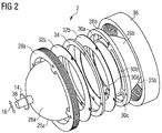
- FIG. 2 shows a three-dimensional technical draw of a mechanochemical device 2, with the different elements composing it.
- the mechanochemical device 2 comprises two half-containers 25a, 25b, each composed by a hollow half-spherical central part 26a, 26b devoted for the pure milling and a circular ring 28a, 28b with several curved apertures 30a to 30d where the analysis may take place.
- Ring disks 32a, 32b act as walls and spacer ring 34 acts as a spacer defining the thickness of the apertures 30a to 30d. All the parts are kept together by a compression nut 36.
- the complete assembly is held by a pin 38 included on the center of each half-container 25a, 26b. These pins 38 define the axle around of which the mechanochemical device 2 can rotate.
- the specific aspect of the invention is to have a milling chamber 7 with a separated probe chamber 10 for the analysis where the milling elements 8 cannot access.
- the probe chamber 10 can therefore have walls of a desired material, e.g. less resistant, harder, shockproof as compared to the wall of the milling chamber 7 that should withstand the impact of the milling elements 8.
- a vigorous mixing of the precursor compounds is ensured between the probe chamber 10 and the milling chamber 7.
- the technical solution is achieved by having a mixing force driven not only by the motion induced into the milling elements 8 but also by gravity, as obtained by providing an additional rotation motion (arrow 14 in Figures 1 and 2 ) in the case of the present examples.
Landscapes
- Engineering & Computer Science (AREA)
- Food Science & Technology (AREA)
- Analysing Materials By The Use Of Radiation (AREA)
Abstract
It is an objective of the present invention to provide a mechanomechanical device improving the quality of the analytical measurements done by diffraction or other analytical techniques (e.g. spectroscopic ones) during ball milling processes.
This objective is achieved according to the present invention by a mechanochemical device (2) for mixing and/or reacting at least one chemical compound to at least one reaction product (4), comprising:
a) a grinding container (6) having a milling chamber (7), milling elements (8) and at least one probing chamber (10) wherein the at least one probing chamber (10) is realized as a recess volume (12) of said milling chamber (7) and wherein the recess volume (12) has a cross-sectional opening towards the milling chamber (7) that is smaller than the dimensions of the milling elements (8) preventing the milling elements (8) from entering into the recess volume (12); and
b) a motor (14, 16) coupled to the grinding container (6) in order to rotate the grinding container (6) thereby bringing the recess volume (12) at least temporarily into a position allowing a gravitation driven release of the at least one compound and/or the at least one reaction product (4) that entered the recess volume (12) back into the milling chamber.
a) a grinding container (6) having a milling chamber (7), milling elements (8) and at least one probing chamber (10) wherein the at least one probing chamber (10) is realized as a recess volume (12) of said milling chamber (7) and wherein the recess volume (12) has a cross-sectional opening towards the milling chamber (7) that is smaller than the dimensions of the milling elements (8) preventing the milling elements (8) from entering into the recess volume (12); and
b) a motor (14, 16) coupled to the grinding container (6) in order to rotate the grinding container (6) thereby bringing the recess volume (12) at least temporarily into a position allowing a gravitation driven release of the at least one compound and/or the at least one reaction product (4) that entered the recess volume (12) back into the milling chamber.
This device enables measurements done in a small part called probe chamber being specifically designed for analytical techniques. The features of the present invention make sure that the reaction product and/or its precursors (the ration strongly depends on the progress of the reaction of the precursors) is quasi-permanently present in the probe chamber which allows for an quasi-permanent analysis on the progress/evolution of the desired mechanochemical-induced reaction.
Description
- The present invention relates to a mechanochemical device for mixing and/or reacting at least one chemical compound to at least one reaction product.
- Nowadays, in situ materials characterization techniques are more and more used as they give an accurate description of the sample in a particular state without disturbing the system and adding supplemental parameters/errors in the measurement. Further, there is a strong interest on in situ real-time measurements, where not only a particular state but the evolution of a particular process is probed. This is possible due to the recent technological progresses of analytical machinery giving more reliable measurements in a very short time-lapse.
- One category of such processes, where in situ and real-time monitoring is important, is that of mechanochemical reactions. Mechanochemistry has attracted a special attention as a promising alternative synthetic strategy to traditional "wet chemistry" methods. The last years have witnessed a renewed interest by the rise of novel grinding methods paving the way to once impossible reactions or improving the yield of a particular final product.
- Ball milling is one of the ways to induce mechanochemical reactions: it involves 'shaking' a container with powder reagents and steel balls, which implies a transfer of kinetic energy from the container to the balls and from the balls to the powder mix, resulting in reactivity. A large body of work exists on ex situ studies, where the materials are reacted and then analyzed.
- The latest state of the art analytical technique is the real-time monitoring of mechanochemical reactions by X-ray diffraction. For the first time, a mechanochemical reaction was real-time monitored by a probe beam, giving direct information on the sample state inside the vessel and not only an indirect one as by probing the vessel temperature or pressure. Combinations with other solid-state techniques such as Raman spectroscopy are considered in order to have a clear understanding of the mechanisms in milling reactions.
- However quick, efficient and good the analytical instrument could be, the container design is often neglected and present work is done with radiation passing through its entire body, leading to increased background and lower resolution. The container design and functionality has to address two main points:
- An improvement in the quality of the experimental data: good signal-to noise ratio enhanced by the path of the incident and outgoing beam probe through the vessel.
- a good mixing of the powder inside the milling chamber: efficient and fast exchange between the milling chamber and the collection area, which is important for obtaining the most representative picture possible of the process happening while collecting data.
- It is therefore an objective of the present invention to provide a mechanomechanical device improving the quality of the analytical measurements done by diffraction or other analytical techniques (e.g. spectroscopic ones) during ball milling processes.
- This objective is achieved according to the present invention by a mechanochemical device for mixing and/or reacting at least one chemical compound to at least one reaction product, comprising:
- a) a grinding container having a milling chamber, milling elements and at least one probing chamber wherein the at least one probing chamber is realized as a recess volume of said milling chamber and wherein the recess volume has a cross-sectional opening towards the milling chamber that is smaller than the dimensions of the milling elements preventing the milling elements from entering into the recess volume; and
- b) a motor coupled to the grinding container in order to rotate the grinding container thereby bringing the recess volume at least temporarily into a position allowing a gravitation driven release of the at least two compounds and/or the reaction product that entered the recess volume back into the milling chamber.
- This device enables measurements done in a small part called probe chamber being specifically designed for analytical techniques. The features of the present invention make sure that the reaction product and/or its precursor(s) (the ration strongly depends on the progress of the reaction of the precursor(s)) is quasi-permanently present in the probe chamber which allows for an quasi-permanent analysis on the progress/evolution of the desired mechanochemical-induced reaction.
- A preferred embodiment of the present invention can be achieved when designing the recess volume as a continuous ring-like groove having a width smaller that the smallest dimension of the mixing elements.
- Suitable mixing and grinding elements can be provided if they are designed as steel balls.
- For a beneficial support of the desired in situ analysis of the evolution of the mechanochemical reaction, the wall of the recess volume can be permeable to light beams, such as X-rays, and/or particle beams, such as protons, neutrons and/or electrons. Suitable materials could be for example mylar® or kapton®.
- Preferably, the wall of the recess volume can be made from a material different from the material used for the wall of the milling chamber. Therefore, the material for the wall of the milling chamber can be optimized for the goal of milling while the material for the wall of the probe chamber can be optimized for the analysis method applied to the material trapped in the recess volume.
- Preferred embodiments of the present invention are hereinafter described in detail with reference to the attached drawings which depict in:
- Figure 1
- schematically the general function principle of a mechanochemical device during analytical acquisitions; and
- Figure 2
- schematically the design of a milling chamber.
-
Figure 1 shows a schematic drawing of the general function principle of amechanochemical device 2 during analytical acquisitions, through a vertical cut of themechanochemical device 2 itself.Figure 1 illustrates the motion of themechanochemical device 2 during a vertical ball milling process. - The
mechanochemical device 2 for mixing and/or reacting at least one chemical compound to at least one reaction product 4 comprises agrinding container 6 having a milling chamber 7,milling elements 8, e.g. steel balls, and aprobing chamber 10. Theprobing chamber 10 is realized as arecess volume 12 of said milling chamber 7. Thisrecess volume 12 has a cross-sectional opening towards the milling chamber 7 that is smaller than the dimensions of themilling elements 8 preventing themilling elements 8 from entering into the recess volume. Further, themechanochemical device 2 comprises two motors (represented byarrows 14 and 16) coupled to thegrinding container 6 in order to shake (arrow 16) and rotate (arrow 14) thegrinding container 6.Arrow 14 indicates this rotation. By this rotation, therecess volume 12 is at least temporarily brought into a position allowing a gravitation driven release of the at least one compound and/or the at least one reaction product 4 that entered therecess volume 12 back into the milling chamber 7. InFigure 1 , this situation is shown for theupper recess area 12 which released all its content back into the milling chamber 7 while the lower recess area 12' is filled with the at least one reaction product 4 and/or the at least one precursor compound of the at least one reaction product 4 which do not have yet reacted to the at least one reaction product 4. - The
grinding container 6 is driven by a general motion here in a direction up and down which is represented by thearrow 16, preferably at a frequency above 10 Hz. This movement is coupled with the slow rotation of thegrinding container 6 that is represented by thearrow 14, preferably with a frequency of less than 0.5 Hz with a rotation axis coaxial to theprobing chamber 10. By this dual motion, the probe indicated by the dashed area in the probe chamber 12' is immediately re-injected in the milling chamber 7 by combined vertical motion and gravity. As a result a fresh portion (always available in the recess volume 12') of the at least one reaction product 4 (the grinding mixture) is continuously examined by anX-ray source 18 emitting anX-ray beam 20 through the recess volume 12'. The transmission of theX-ray beam 20 is not affected by themilling elements 8 due to the design of the cross-sectional opening of therecess volume 12, 12' to the milling chamber 7, where themilling elements 8 can not enter in due to the larger dimensions as compared to the dimensions of the cross-sectional opening. After the penetration of the recess volume 12', a diffracted beam 22 (diffracted by the probe in the recess volume 12') is detected by adetector 24. Since themilling elements 8 cannot access into therecess volume 12, 12', the path of theprobing X-ray beam 20 and the transmission of the outgoing diffractedbeam 22 and thus the quality of data acquisitions is tremendously improved as compared to prior art grinding devices. -
Figure 2 shows a three-dimensional technical draw of amechanochemical device 2, with the different elements composing it. Themechanochemical device 2 comprises two half-containers central part circular ring curved apertures 30a to 30d where the analysis may take place.Ring disks spacer ring 34 acts as a spacer defining the thickness of theapertures 30a to 30d. All the parts are kept together by acompression nut 36. The complete assembly is held by apin 38 included on the center of each half-container pins 38 define the axle around of which themechanochemical device 2 can rotate. - In a standard apparatus the mixing of solids is done by the motion of the
milling elements 8 which ensures the homogeneous mixing of powders, important for reactivity. Where arecess volume 12, 12' exists the solid can get stuck into it. - The specific aspect of the invention is to have a milling chamber 7 with a
separated probe chamber 10 for the analysis where themilling elements 8 cannot access. Theprobe chamber 10 can therefore have walls of a desired material, e.g. less resistant, harder, shockproof as compared to the wall of the milling chamber 7 that should withstand the impact of themilling elements 8. Coincidentally, a vigorous mixing of the precursor compounds is ensured between theprobe chamber 10 and the milling chamber 7. The technical solution is achieved by having a mixing force driven not only by the motion induced into themilling elements 8 but also by gravity, as obtained by providing an additional rotation motion (arrow 14 inFigures 1 and2 ) in the case of the present examples.
Claims (5)
- Mechanochemical device (2) for mixing and/or reacting at least one chemical compound to at least one reaction product (4), comprising:a) a grinding container (6) having a milling chamber (7), milling elements (8) and at least one probing chamber (10) wherein the at least one probing chamber (10) is realized as a recess volume (12) of said milling chamber (7) and wherein the recess volume (12) has a cross-sectional opening towards the milling chamber (7) that is smaller than the dimensions of the milling elements (8) preventing the milling elements (8) from entering into the recess volume (12); andb) a motor (14, 16) coupled to the grinding container (6) in order to rotate the grinding container (6) thereby bringing the recess volume (12) at least temporarily into a position allowing a gravitation driven release of the at least one compounds and/or the at least one reaction product (4) that entered the recess volume (12) back into the milling chamber (7).
- Mechanochemical device (2) according to claims 1 wherein the recess volume (12) is designed as a continuous ring-like groove (10) having a width smaller that the smallest dimension of the mixing elements (8).
- Mechanochemical device (2) according to claim 1 or 2, wherein the mixing elements (8) are steel balls.
- Mechanochemical device (2) according to any of the preceding claims, wherein the wall of the recess volume (12) is permeable to light beams (20), such as X-rays, and/or particle beams, such as protons, neutrons and/or electrons.
- Mechanochemical device (2) according to any of the preceding claims, wherein the wall of the recess volume (12) is made from a material different from the material used for the wall of the milling chamber (7).
Priority Applications (1)
| Application Number | Priority Date | Filing Date | Title |
|---|---|---|---|
| EP15197992.9A EP3175913A1 (en) | 2015-12-04 | 2015-12-04 | Mechanochemical device for mixing and/or reacting at least one chemical compound to at least one reaction product |
Applications Claiming Priority (1)
| Application Number | Priority Date | Filing Date | Title |
|---|---|---|---|
| EP15197992.9A EP3175913A1 (en) | 2015-12-04 | 2015-12-04 | Mechanochemical device for mixing and/or reacting at least one chemical compound to at least one reaction product |
Publications (1)
| Publication Number | Publication Date |
|---|---|
| EP3175913A1 true EP3175913A1 (en) | 2017-06-07 |
Family
ID=55027237
Family Applications (1)
| Application Number | Title | Priority Date | Filing Date |
|---|---|---|---|
| EP15197992.9A Withdrawn EP3175913A1 (en) | 2015-12-04 | 2015-12-04 | Mechanochemical device for mixing and/or reacting at least one chemical compound to at least one reaction product |
Country Status (1)
| Country | Link |
|---|---|
| EP (1) | EP3175913A1 (en) |
Cited By (2)
| Publication number | Priority date | Publication date | Assignee | Title |
|---|---|---|---|---|
| CN109499475A (en) * | 2019-01-05 | 2019-03-22 | 汪通鲜 | A kind of multifunctional fertilizers pelletizer |
| JP2019104005A (en) * | 2017-12-14 | 2019-06-27 | 株式会社栗本鐵工所 | Mechanical chemical modification method and modification device |
Citations (2)
| Publication number | Priority date | Publication date | Assignee | Title |
|---|---|---|---|---|
| EP2246113A1 (en) * | 2009-04-29 | 2010-11-03 | Sandvik Intellectual Property AB | Process for milling cermet or cemented carbide powder mixtures |
| US20110100928A1 (en) * | 2009-11-02 | 2011-05-05 | Lehigh University | Preparation and use of nano size peroxide particles |
-
2015
- 2015-12-04 EP EP15197992.9A patent/EP3175913A1/en not_active Withdrawn
Patent Citations (2)
| Publication number | Priority date | Publication date | Assignee | Title |
|---|---|---|---|---|
| EP2246113A1 (en) * | 2009-04-29 | 2010-11-03 | Sandvik Intellectual Property AB | Process for milling cermet or cemented carbide powder mixtures |
| US20110100928A1 (en) * | 2009-11-02 | 2011-05-05 | Lehigh University | Preparation and use of nano size peroxide particles |
Cited By (2)
| Publication number | Priority date | Publication date | Assignee | Title |
|---|---|---|---|---|
| JP2019104005A (en) * | 2017-12-14 | 2019-06-27 | 株式会社栗本鐵工所 | Mechanical chemical modification method and modification device |
| CN109499475A (en) * | 2019-01-05 | 2019-03-22 | 汪通鲜 | A kind of multifunctional fertilizers pelletizer |
Similar Documents
| Publication | Publication Date | Title |
|---|---|---|
| Ketenoglu | A general overview and comparative interpretation on element‐specific X‐ray spectroscopy techniques: XPS, XAS, and XRS | |
| Blake et al. | Characterization and calibration of the CheMin mineralogical instrument on Mars Science Laboratory | |
| RU2600058C2 (en) | Automated sample preparation | |
| US8311183B2 (en) | Online energy dispersive X-ray diffraction analyser | |
| EP3175913A1 (en) | Mechanochemical device for mixing and/or reacting at least one chemical compound to at least one reaction product | |
| RU2314517C2 (en) | Diffractometer and method of diffraction analysis | |
| Kuo et al. | Final analysis: Characterisation of catalysts using secondary and backscattered electron in-lens detectors | |
| Shen et al. | High-pressure apparatus integrated with synchrotron radiation | |
| Patterson et al. | Three‐dimensional density measurements of ultra low density materials by X‐ray scatter using confocal micro X‐ray fluorescence spectroscopy | |
| EP3226279B1 (en) | Sample holder and focused ion beam apparatus | |
| Lanzirotti et al. | Practical application of synchrotron-based hard X-ray microprobes in soil sciences | |
| JP5684032B2 (en) | Charged particle beam analyzer and analysis method | |
| Yan et al. | Synchrotron studies of functional interfaces and the state of the art: A perspective | |
| Bufon et al. | A novel multi-cell silicon drift detector for Low Energy X-Ray Fluorescence (LEXRF) spectroscopy | |
| Andrew et al. | Non-invasive 3D crystallography of geological media in the laboratory | |
| Kularatne et al. | Maximizing Rock-Forming Minerals Differentiation with Laboratory Spectral X-Ray Computed Tomography | |
| Michalchuk et al. | Dispersive X-Ray Absorption Spectroscopy for Time-Resolved In Situ Monitoring of Mechanochemical Reactions | |
| Hayashi et al. | Highly Resolved Mn K β Emission: A Potential Probe in Laboratory for Analysis of Ligand Coordination around Mn Atoms in Gels and Solutions | |
| EP4439058A1 (en) | Crystal structure analysis method, crystal structure analysis device, and crystal structure analysis program | |
| Marinangeli et al. | An X-Rays tomographer (Tomox) for in situ planetary exploration | |
| Robba | A comprensive spectral-timing study of Ultraluminous X-ray sources | |
| McKee | High energy proton PIXE [HEPP] | |
| Xue et al. | Characterization of Carbonaceous Materials in a Gold Loading Study by Micro-XRF Imaging and Raman Spectroscopy | |
| Dluhoš et al. | 3D Multi-modal Elemental Characterization of Li-Ion Battery Components using SEM, EDS and ToF SIMS in the FIB-SEM Tomography | |
| Adams et al. | 5.4 Synchrotron Radiation for Microscopic X-ray Fluorescence Analysis |
Legal Events
| Date | Code | Title | Description |
|---|---|---|---|
| AK | Designated contracting states |
Kind code of ref document: A1 Designated state(s): AL AT BE BG CH CY CZ DE DK EE ES FI FR GB GR HR HU IE IS IT LI LT LU LV MC MK MT NL NO PL PT RO RS SE SI SK SM TR |
|
| AX | Request for extension of the european patent |
Extension state: BA ME |
|
| PUAI | Public reference made under article 153(3) epc to a published international application that has entered the european phase |
Free format text: ORIGINAL CODE: 0009012 |
|
| STAA | Information on the status of an ep patent application or granted ep patent |
Free format text: STATUS: THE APPLICATION IS DEEMED TO BE WITHDRAWN |
|
| 18D | Application deemed to be withdrawn |
Effective date: 20171208 |