EP3175641B1 - On-boarding einer vorrichtung zu einem sicheren lokalen netzwerk - Google Patents
On-boarding einer vorrichtung zu einem sicheren lokalen netzwerk Download PDFInfo
- Publication number
- EP3175641B1 EP3175641B1 EP15760531.2A EP15760531A EP3175641B1 EP 3175641 B1 EP3175641 B1 EP 3175641B1 EP 15760531 A EP15760531 A EP 15760531A EP 3175641 B1 EP3175641 B1 EP 3175641B1
- Authority
- EP
- European Patent Office
- Prior art keywords
- iot
- control device
- local network
- secure local
- operator
- Prior art date
- Legal status (The legal status is an assumption and is not a legal conclusion. Google has not performed a legal analysis and makes no representation as to the accuracy of the status listed.)
- Active
Links
- 238000000034 method Methods 0.000 claims description 38
- 230000004044 response Effects 0.000 claims description 9
- 238000002604 ultrasonography Methods 0.000 claims description 2
- 238000013475 authorization Methods 0.000 claims 4
- 230000003213 activating effect Effects 0.000 claims 1
- 238000004891 communication Methods 0.000 description 93
- 230000006870 function Effects 0.000 description 37
- 230000008569 process Effects 0.000 description 17
- 230000001105 regulatory effect Effects 0.000 description 6
- 230000009471 action Effects 0.000 description 5
- 230000000694 effects Effects 0.000 description 5
- 235000015205 orange juice Nutrition 0.000 description 5
- 238000012545 processing Methods 0.000 description 5
- 230000005540 biological transmission Effects 0.000 description 4
- 230000005611 electricity Effects 0.000 description 4
- 238000005516 engineering process Methods 0.000 description 4
- 230000036541 health Effects 0.000 description 4
- 230000003287 optical effect Effects 0.000 description 4
- 238000011161 development Methods 0.000 description 3
- 230000018109 developmental process Effects 0.000 description 3
- 239000007789 gas Substances 0.000 description 3
- 230000007246 mechanism Effects 0.000 description 3
- 238000004378 air conditioning Methods 0.000 description 2
- 230000008901 benefit Effects 0.000 description 2
- 230000001413 cellular effect Effects 0.000 description 2
- 239000003795 chemical substances by application Substances 0.000 description 2
- 239000003086 colorant Substances 0.000 description 2
- 238000001514 detection method Methods 0.000 description 2
- 239000000835 fiber Substances 0.000 description 2
- 230000003993 interaction Effects 0.000 description 2
- 238000007726 management method Methods 0.000 description 2
- 238000005259 measurement Methods 0.000 description 2
- VNWKTOKETHGBQD-UHFFFAOYSA-N methane Chemical compound C VNWKTOKETHGBQD-UHFFFAOYSA-N 0.000 description 2
- 238000012544 monitoring process Methods 0.000 description 2
- 239000002245 particle Substances 0.000 description 2
- XLYOFNOQVPJJNP-UHFFFAOYSA-N water Substances O XLYOFNOQVPJJNP-UHFFFAOYSA-N 0.000 description 2
- 230000032683 aging Effects 0.000 description 1
- 238000004590 computer program Methods 0.000 description 1
- 238000007596 consolidation process Methods 0.000 description 1
- 238000001816 cooling Methods 0.000 description 1
- 238000013461 design Methods 0.000 description 1
- 230000035622 drinking Effects 0.000 description 1
- 210000005069 ears Anatomy 0.000 description 1
- 230000007613 environmental effect Effects 0.000 description 1
- 238000011156 evaluation Methods 0.000 description 1
- 230000003203 everyday effect Effects 0.000 description 1
- 238000007519 figuring Methods 0.000 description 1
- 238000010438 heat treatment Methods 0.000 description 1
- 230000010354 integration Effects 0.000 description 1
- 230000007774 longterm Effects 0.000 description 1
- 238000012986 modification Methods 0.000 description 1
- 230000004048 modification Effects 0.000 description 1
- 239000003345 natural gas Substances 0.000 description 1
- 230000000737 periodic effect Effects 0.000 description 1
- 238000012552 review Methods 0.000 description 1
- 230000001953 sensory effect Effects 0.000 description 1
- 238000012546 transfer Methods 0.000 description 1
- 230000001960 triggered effect Effects 0.000 description 1
- 238000012795 verification Methods 0.000 description 1
Images


Classifications
-
- H—ELECTRICITY
- H04—ELECTRIC COMMUNICATION TECHNIQUE
- H04W—WIRELESS COMMUNICATION NETWORKS
- H04W12/00—Security arrangements; Authentication; Protecting privacy or anonymity
- H04W12/08—Access security
-
- G—PHYSICS
- G06—COMPUTING; CALCULATING OR COUNTING
- G06F—ELECTRIC DIGITAL DATA PROCESSING
- G06F9/00—Arrangements for program control, e.g. control units
- G06F9/06—Arrangements for program control, e.g. control units using stored programs, i.e. using an internal store of processing equipment to receive or retain programs
- G06F9/44—Arrangements for executing specific programs
- G06F9/4401—Bootstrapping
- G06F9/4411—Configuring for operating with peripheral devices; Loading of device drivers
-
- H—ELECTRICITY
- H04—ELECTRIC COMMUNICATION TECHNIQUE
- H04L—TRANSMISSION OF DIGITAL INFORMATION, e.g. TELEGRAPHIC COMMUNICATION
- H04L67/00—Network arrangements or protocols for supporting network services or applications
- H04L67/01—Protocols
- H04L67/12—Protocols specially adapted for proprietary or special-purpose networking environments, e.g. medical networks, sensor networks, networks in vehicles or remote metering networks
-
- H—ELECTRICITY
- H04—ELECTRIC COMMUNICATION TECHNIQUE
- H04W—WIRELESS COMMUNICATION NETWORKS
- H04W12/00—Security arrangements; Authentication; Protecting privacy or anonymity
- H04W12/50—Secure pairing of devices
-
- H—ELECTRICITY
- H04—ELECTRIC COMMUNICATION TECHNIQUE
- H04W—WIRELESS COMMUNICATION NETWORKS
- H04W4/00—Services specially adapted for wireless communication networks; Facilities therefor
- H04W4/70—Services for machine-to-machine communication [M2M] or machine type communication [MTC]
-
- H—ELECTRICITY
- H04—ELECTRIC COMMUNICATION TECHNIQUE
- H04W—WIRELESS COMMUNICATION NETWORKS
- H04W48/00—Access restriction; Network selection; Access point selection
- H04W48/08—Access restriction or access information delivery, e.g. discovery data delivery
-
- H—ELECTRICITY
- H04—ELECTRIC COMMUNICATION TECHNIQUE
- H04W—WIRELESS COMMUNICATION NETWORKS
- H04W12/00—Security arrangements; Authentication; Protecting privacy or anonymity
- H04W12/06—Authentication
-
- H—ELECTRICITY
- H04—ELECTRIC COMMUNICATION TECHNIQUE
- H04W—WIRELESS COMMUNICATION NETWORKS
- H04W12/00—Security arrangements; Authentication; Protecting privacy or anonymity
- H04W12/60—Context-dependent security
- H04W12/63—Location-dependent; Proximity-dependent
-
- H—ELECTRICITY
- H04—ELECTRIC COMMUNICATION TECHNIQUE
- H04W—WIRELESS COMMUNICATION NETWORKS
- H04W12/00—Security arrangements; Authentication; Protecting privacy or anonymity
- H04W12/60—Context-dependent security
- H04W12/65—Environment-dependent, e.g. using captured environmental data
-
- H—ELECTRICITY
- H04—ELECTRIC COMMUNICATION TECHNIQUE
- H04W—WIRELESS COMMUNICATION NETWORKS
- H04W48/00—Access restriction; Network selection; Access point selection
- H04W48/02—Access restriction performed under specific conditions
- H04W48/04—Access restriction performed under specific conditions based on user or terminal location or mobility data, e.g. moving direction, speed
-
- H—ELECTRICITY
- H04—ELECTRIC COMMUNICATION TECHNIQUE
- H04W—WIRELESS COMMUNICATION NETWORKS
- H04W8/00—Network data management
- H04W8/005—Discovery of network devices, e.g. terminals
Definitions
- Various embodiments described herein generally relate to on-boarding a device to a secure local network.
- the Internet is a global system of interconnected computers and computer networks that use a standard Internet protocol suite (e.g., the Transmission Control Protocol (TCP) and Internet Protocol (IP)) to communicate with each other.
- TCP Transmission Control Protocol
- IP Internet Protocol
- the Internet of Things (IoT) is based on the idea that everyday objects, not just computers and computer networks, can be readable, recognizable, locatable, addressable, and controllable via an IoT communications network (e.g., an ad-hoc system or the Internet).
- a number of market trends are driving development of IoT devices. For example, increasing energy costs are driving governments' strategic investments in smart grids and support for future consumption, such as for electric vehicles and public charging stations. Increasing health care costs and aging populations are driving development for remote/connected health care and fitness services. A technological revolution in the home is driving development for new "smart" services, including consolidation by service providers marketing 'N' play (e.g., data, voice, video, security, energy management, etc.) and expanding home networks. Buildings are getting smarter and more convenient as a means to reduce operational costs for enterprise facilities.
- IoT There are a number of key applications for the IoT.
- IoT in the area of smart grids and energy management, utility companies can optimize delivery of energy to homes and businesses while customers can better manage energy usage.
- smart homes and buildings can have centralized control over virtually any device or system in the home or office, from appliances to plug-in electric vehicle (PEV) security systems.
- PEV plug-in electric vehicle
- enterprise companies, hospitals, factories, and other large organizations can accurately track the locations of high-value equipment, patients, vehicles, and so on.
- doctors can remotely monitor patients' health while people can track the progress of fitness routines.
- Some on-boarding solutions for IoT networks require each prospective IoT device to announce itself to the IoT network via a service set identifier (SSID), whereby the SSID for the prospective IoT device appears in a list of WiFi hotspots on an operator's client device.
- the operator of the client device selects a device from the list of WiFi hotspots via its associated SSID, after which the client devices sends credentials for the IoT network to the selected device.
- the selected device then uses the IoT network credentials to join the IoT network.
- the SSID (or hotspot name) for a particular IoT device is preconfigured by a manufacturer of the associated IoT device.
- a manufacturer of the associated IoT device e.g., a phone, an appliance such as a lamp or coffee maker, etc.
- the operator's client device may detect eight (8) different lamps and show their associated SSIDs in the list of WiFi hotspots, and the operator may not be able to easily figure out how to correlate the respective lamps to their associated SSIDs in the list of WiFi hotspots.
- Document WO 2014/094849 discloses user equipment accessibility indication for WiFi integration in a Radio Access Network.
- a control device that is configured to onboard a target device to a secure local network by discovering a set of devices over a bootstrapping interface, establishing a bootstrap connection to at least one device from the set of devices in response to the discovery without authorizing the at least one device to access the secure local network, instructing the at least one device via the bootstrap connection to activate an observable function that is configured to be observable to one or more observation entities that are separate from the control device and are in proximity to the at least one device, determining whether an operator of the control device verifies that the observable function has been successfully detected as performed by the target device and selectively authorizing the at least one device to access the secure local network based on the determination.
- IoT device may refer to any object (e.g., an appliance, a sensor, etc.) that has an addressable interface (e.g., an Internet protocol (IP) address, a Bluetooth identifier (ID), a near-field communication (NFC) ID, etc.) and can transmit information to one or more other devices over a wired or wireless connection.
- IP Internet protocol
- ID Bluetooth identifier
- NFC near-field communication
- An IoT device may have a passive communication interface, such as a quick response (QR) code, a radio-frequency identification (RFID) tag, an NFC tag, or the like, or an active communication interface, such as a modem, a transceiver, a transmitter-receiver, or the like.
- QR quick response
- RFID radio-frequency identification
- An IoT device can have a particular set of attributes (e.g., a device state or status, such as whether the IoT device is on or off, open or closed, idle or active, available for task execution or busy, and so on, a cooling or heating function, an environmental monitoring or recording function, a light-emitting function, a sound-emitting function, etc.) that can be embedded in and/or controlled/monitored by a central processing unit (CPU), microprocessor, ASIC, or the like, and configured for connection to an IoT network such as a local ad-hoc network or the Internet.
- a device state or status such as whether the IoT device is on or off, open or closed, idle or active, available for task execution or busy, and so on, a cooling or heating function, an environmental monitoring or recording function, a light-emitting function, a sound-emitting function, etc.
- CPU central processing unit
- ASIC application specific integrated circuitry
- IoT devices may include, but are not limited to, refrigerators, toasters, ovens, microwaves, freezers, dishwashers, dishes, hand tools, clothes washers, clothes dryers, furnaces, air conditioners, thermostats, televisions, light fixtures, vacuum cleaners, sprinklers, electricity meters, gas meters, etc., so long as the devices are equipped with an addressable communications interface for communicating with the IoT network.
- IoT devices may also include cell phones, desktop computers, laptop computers, tablet computers, personal digital assistants (PDAs), etc.
- the IoT network may be comprised of a combination of "legacy" Internet-accessible devices (e.g., laptop or desktop computers, cell phones, etc.) in addition to devices that do not typically have Internet-connectivity (e.g., dishwashers, etc.).
- “legacy” Internet-accessible devices e.g., laptop or desktop computers, cell phones, etc.
- devices that do not typically have Internet-connectivity e.g., dishwashers, etc.
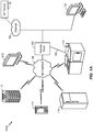
- FIG. 1A illustrates a high-level system architecture of a wireless communications system 100A in accordance with an aspect of the disclosure.
- the wireless communications system 100A contains a plurality of IoT devices, which include a television 110, an outdoor air conditioning unit 112, a thermostat 114, a refrigerator 116, and a washer and dryer 118.
- IoT devices 110-118 are configured to communicate with an access network (e.g., an access point 125) over a physical communications interface or layer, shown in FIG. 1A as air interface 108 and a direct wired connection 109.
- the air interface 108 can comply with a wireless Internet protocol (IP), such as IEEE 802.11.
- IP wireless Internet protocol
- FIG. 1A illustrates IoT devices 110-118 communicating over the air interface 108 and IoT device 118 communicating over the direct wired connection 109, each IoT device may communicate over a wired or wireless connection, or both.
- the Internet 175 includes a number of routing agents and processing agents (not shown in FIG. 1A for the sake of convenience).
- the Internet 175 is a global system of interconnected computers and computer networks that uses a standard Internet protocol suite (e.g., the Transmission Control Protocol (TCP) and IP) to communicate among disparate devices/networks.
- TCP/IP provides end-to-end connectivity specifying how data should be formatted, addressed, transmitted, routed and received at the destination.
- a computer 120 such as a desktop or personal computer (PC) is shown as connecting to the Internet 175 directly (e.g., over an Ethernet connection or Wi-Fi or 802.11-based network).
- the computer 120 may have a wired connection to the Internet 175, such as a direct connection to a modem or router, which, in an example, can correspond to the access point 125 itself (e.g., for a Wi-Fi router with both wired and wireless connectivity).
- the computer 120 may be connected to the access point 125 over air interface 108 or another wireless interface, and access the Internet 175 over the air interface 108.
- computer 120 may be a laptop computer, a tablet computer, a PDA, a smart phone, or the like.
- the computer 120 may be an IoT device and/or contain functionality to manage an IoT network/group, such as the network/group of IoT devices 110-118.
- the access point 125 may be connected to the Internet 175 via, for example, an optical communication system, such as FiOS, a cable modem, a digital subscriber line (DSL) modem, or the like.
- the access point 125 may communicate with IoT devices 110-120 and the Internet 175 using the standard Internet protocols (e.g., TCP/IP).
- an IoT server 170 is shown as connected to the Internet 175.
- the IoT server 170 can be implemented as a plurality of structurally separate servers, or alternately may correspond to a single server.
- the IoT server 170 is optional (as indicated by the dotted line), and the group of IoT devices 110-120 may be a peer-to-peer (P2P) network.
- P2P peer-to-peer
- the IoT devices 110-120 can communicate with each other directly over the air interface 108 and/or the direct wired connection 109.
- some or all of IoT devices 110-120 may be configured with a communication interface independent of air interface 108 and direct wired connection 109.
- the air interface 108 corresponds to a Wi-Fi interface
- one or more of the IoT devices 110-120 may have Bluetooth or NFC interfaces for communicating directly with each other or other Bluetooth or NFC-enabled devices.
- service discovery schemes can multicast the presence of nodes, their capabilities, and group membership.
- the peer-to-peer devices can establish associations and subsequent interactions based on this information.
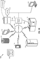
- FIG. 1B illustrates a high-level architecture of another wireless communications system 100B that contains a plurality of IoT devices.
- the wireless communications system 100B shown in FIG. 1B may include various components that are the same and/or substantially similar to the wireless communications system 100A shown in FIG.
- various IoT devices including a television 110, outdoor air conditioning unit 112, thermostat 114, refrigerator 116, and washer and dryer 118, that are configured to communicate with an access point 125 over an air interface 108 and/or a direct wired connection 109, a computer 120 that directly connects to the Internet 175 and/or connects to the Internet 175 through access point 125, and an IoT server 170 accessible via the Internet 175, etc.
- various IoT devices including a television 110, outdoor air conditioning unit 112, thermostat 114, refrigerator 116, and washer and dryer 118, that are configured to communicate with an access point 125 over an air interface 108 and/or a direct wired connection 109, a computer 120 that directly connects to the Internet 175 and/or connects to the Internet 175 through access point 125, and an IoT server 170 accessible via the Internet 175, etc.
- FIG. 1B various details relating to certain components in the wireless communications system 100B shown in FIG. 1B may be omitted herein to the extent that the same or
- the wireless communications system 100B may include a supervisor device 130, which may alternatively be referred to as an IoT manager 130 or IoT manager device 130.
- a supervisor device 130 which may alternatively be referred to as an IoT manager 130 or IoT manager device 130.
- IoT manager 130 the wireless communications system 100B may include a supervisor device 130, which may alternatively be referred to as an IoT manager 130 or IoT manager device 130.
- supervisor device 130 any references to an IoT manager, group owner, or similar terminology may refer to the supervisor device 130 or another physical or logical component that provides the same or substantially similar functionality.
- the supervisor device 130 may generally observe, monitor, control, or otherwise manage the various other components in the wireless communications system 100B.
- the supervisor device 130 can communicate with an access network (e.g., access point 125) over air interface 108 and/or a direct wired connection 109 to monitor or manage attributes, activities, or other states associated with the various IoT devices 110-120 in the wireless communications system 100B.
- the supervisor device 130 may have a wired or wireless connection to the Internet 175 and optionally to the IoT server 170 (shown as a dotted line).
- the supervisor device 130 may obtain information from the Internet 175 and/or the IoT server 170 that can be used to further monitor or manage attributes, activities, or other states associated with the various IoT devices 110-120.
- the supervisor device 130 may be a standalone device or one of IoT devices 110-120, such as computer 120.
- the supervisor device 130 may be a physical device or a software application running on a physical device.
- the supervisor device 130 may include a user interface that can output information relating to the monitored attributes, activities, or other states associated with the IoT devices 110-120 and receive input information to control or otherwise manage the attributes, activities, or other states associated therewith.
- the supervisor device 130 may generally include various components and support various wired and wireless communication interfaces to observe, monitor, control, or otherwise manage the various components in the wireless communications system 100B.
- the wireless communications system 100B shown in FIG. 1B may include one or more passive IoT devices 105 (in contrast to the active IoT devices 110-120) that can be coupled to or otherwise made part of the wireless communications system 100B.
- the passive IoT devices 105 may include barcoded devices, Bluetooth devices, radio frequency (RF) devices, RFID tagged devices, infrared (IR) devices, NFC tagged devices, or any other suitable device that can provide its identifier and attributes to another device when queried over a short range interface.
- Active IoT devices may detect, store, communicate, act on, and/or the like, changes in attributes of passive IoT devices.
- passive IoT devices 105 may include a coffee cup and a container of orange juice that each have an RFID tag or barcode.
- a cabinet IoT device and the refrigerator IoT device 116 may each have an appropriate scanner or reader that can read the RFID tag or barcode to detect when the coffee cup and/or the container of orange juice passive IoT devices 105 have been added or removed.
- the supervisor device 130 may receive one or more signals that relate to the activities detected at the cabinet IoT device and the refrigerator IoT device 116. The supervisor device 130 may then infer that a user is drinking orange juice from the coffee cup and/or likes to drink orange juice from a coffee cup.
- the passive IoT devices 105 may include one or more devices or other physical objects that do not have such communication capabilities.
- certain IoT devices may have appropriate scanner or reader mechanisms that can detect shapes, sizes, colors, and/or other observable features associated with the passive IoT devices 105 to identify the passive IoT devices 105.
- any suitable physical object may communicate its identity and attributes and become part of the wireless communication system 100B and be observed, monitored, controlled, or otherwise managed with the supervisor device 130.
- passive IoT devices 105 may be coupled to or otherwise made part of the wireless communications system 100A in FIG. 1A and observed, monitored, controlled, or otherwise managed in a substantially similar manner.
- FIG. 1C illustrates a high-level architecture of another wireless communications system 100C that contains a plurality of IoT devices.
- the wireless communications system 100C shown in FIG. 1C may include various components that are the same and/or substantially similar to the wireless communications systems 100A and 100B shown in FIGS. 1A and 1B , respectively, which were described in greater detail above.
- various details relating to certain components in the wireless communications system 100C shown in FIG. 1C may be omitted herein to the extent that the same or similar details have already been provided above in relation to the wireless communications systems 100A and 100B illustrated in FIGS. 1A and 1B , respectively.
- the communications system 100C shown in FIG. 1C illustrates exemplary peer-to-peer communications between the IoT devices 110-118 and the supervisor device 130.
- the supervisor device 130 communicates with each of the IoT devices 110-118 over an IoT supervisor interface.
- IoT devices 110 and 114, IoT devices 112, 114, and 116, and IoT devices 116 and 118 communicate directly with each other.
- the IoT devices 110-118 make up an IoT group 160.
- An IoT device group 160 is a group of locally connected IoT devices, such as the IoT devices connected to a user's home network.
- multiple IoT device groups may be connected to and/or communicate with each other via an IoT SuperAgent 140 connected to the Internet 175.
- the supervisor device 130 manages intra-group communications, while the IoT SuperAgent 140 can manage inter-group communications.
- the supervisor device 130 and the IoT SuperAgent 140 may be, or reside on, the same device (e.g., a standalone device or an IoT device, such as computer 120 in FIG. 1A ).
- the IoT SuperAgent 140 may correspond to or include the functionality of the access point 125.
- the IoT SuperAgent 140 may correspond to or include the functionality of an IoT server, such as IoT server 170.
- the IoT SuperAgent 140 may encapsulate gateway functionality 145.
- Each IoT device 110-118 can treat the supervisor device 130 as a peer and transmit attribute/schema updates to the supervisor device 130.
- an IoT device needs to communicate with another IoT device, it can request the pointer to that IoT device from the supervisor device 130 and then communicate with the target IoT device as a peer.
- the IoT devices 110-118 communicate with each other over a peer-to-peer communication network using a common messaging protocol (CMP). As long as two IoT devices are CMP-enabled and connected over a common communication transport, they can communicate with each other.
- CMP common messaging protocol
- the CMP layer 154 is below the application layer 152 and above the transport layer 156 and the physical layer 158.
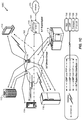
- FIG. ID illustrates a high-level architecture of another wireless communications system 100D that contains a plurality of IoT devices.
- the wireless communications system 100D shown in FIG. ID may include various components that are the same and/or substantially similar to the wireless communications systems 100A-C shown in FIGS. 1A-C , respectively, which were described in greater detail above.
- various details relating to certain components in the wireless communications system 100D shown in FIG. ID may be omitted herein to the extent that the same or similar details have already been provided above in relation to the wireless communications systems 100A-C illustrated in FIGS. 1A-C , respectively.
- the Internet 175 is a "resource” that can be regulated using the concept of the IoT.
- the Internet 175 is just one example of a resource that is regulated, and any resource could be regulated using the concept of the IoT.
- Other resources that can be regulated include, but are not limited to, electricity, gas, storage, security, and the like.
- An IoT device may be connected to the resource and thereby regulate it, or the resource could be regulated over the Internet 175.
- FIG. ID illustrates several resources 180, such as natural gas, gasoline, hot water, and electricity, wherein the resources 180 can be regulated in addition to and/or over the Internet 175.
- IoT devices can communicate with each other to regulate their use of a resource 180.
- IoT devices such as a toaster, a computer, and a hairdryer may communicate with each other over a Bluetooth communication interface to regulate their use of electricity (the resource 180).
- IoT devices such as a desktop computer, a telephone, and a tablet computer may communicate over a Wi-Fi communication interface to regulate their access to the Internet 175 (the resource 180).
- IoT devices such as a stove, a clothes dryer, and a water heater may communicate over a Wi-Fi communication interface to regulate their use of gas.
- each IoT device may be connected to an IoT server, such as IoT server 170, which has logic to regulate their use of the resource 180 based on information received from the IoT devices.
- FIG. IE illustrates a high-level architecture of another wireless communications system 100E that contains a plurality of IoT devices.
- the wireless communications system 100E shown in FIG. IE may include various components that are the same and/or substantially similar to the wireless communications systems 100A-D shown in FIGS. 1A-D , respectively, which were described in greater detail above.
- various details relating to certain components in the wireless communications system 100E shown in FIG. IE may be omitted herein to the extent that the same or similar details have already been provided above in relation to the wireless communications systems 100A-D illustrated in FIGS. 1A-D , respectively.
- the communications system 100E includes two IoT device groups 160A and 160B. Multiple IoT device groups may be connected to and/or communicate with each other via an IoT SuperAgent connected to the Internet 175. At a high level, an IoT SuperAgent may manage inter-group communications among IoT device groups. For example, in FIG. IE, the IoT device group 160A includes IoT devices 116A, 122A, and 124A and an IoT SuperAgent 140A, while IoT device group 160B includes IoT devices 116B, 122B, and 124B and an IoT SuperAgent 140B.
- the IoT SuperAgents 140A and 140B may connect to the Internet 175 and communicate with each other over the Internet 175 and/or communicate with each other directly to facilitate communication between the IoT device groups 160A and 160B.
- FIG. IE illustrates two IoT device groups 160A and 160B communicating with each other via IoT SuperAgents 140A and 140B, those skilled in the art will appreciate that any number of IoT device groups may suitably communicate with each other using IoT SuperAgents.
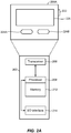
- FIG. 2A illustrates a high-level example of an IoT device 200A in accordance with aspects of the disclosure. While external appearances and/or internal components can differ significantly among IoT devices, most IoT devices will have some sort of user interface, which may comprise a display and a means for user input. IoT devices without a user interface can be communicated with remotely over a wired or wireless network, such as air interface 108 in FIGS. 1A-B .
- a wired or wireless network such as air interface 108 in FIGS. 1A-B .
- an external casing of IoT device 200A may be configured with a display 226, a power button 222, and two control buttons 224A and 224B, among other components, as is known in the art.
- the display 226 may be a touchscreen display, in which case the control buttons 224A and 224B may not be necessary.
- the IoT device 200A may include one or more external antennas and/or one or more integrated antennas that are built into the external casing, including but not limited to Wi-Fi antennas, cellular antennas, satellite position system (SPS) antennas (e.g., global positioning system (GPS) antennas), and so on.
- Wi-Fi antennas e.g., Wi-Fi
- cellular antennas e.g., cellular antennas
- SPS satellite position system
- GPS global positioning system
- IoT device 200A While internal components of IoT devices, such as IoT device 200A, can be embodied with different hardware configurations, a basic high-level configuration for internal hardware components is shown as platform 202 in FIG. 2A .
- the platform 202 can receive and execute software applications, data and/or commands transmitted over a network interface, such as air interface 108 in FIGS. 1A-B and/or a wired interface.
- the platform 202 can also independently execute locally stored applications.
- the platform 202 can include one or more transceivers 206 configured for wired and/or wireless communication (e.g., a Wi-Fi transceiver, a Bluetooth transceiver, a cellular transceiver, a satellite transceiver, a GPS or SPS receiver, etc.) operably coupled to one or more processors 208, such as a microcontroller, microprocessor, application specific integrated circuit, digital signal processor (DSP), programmable logic circuit, or other data processing device, which will be generally referred to as processor 208.
- the processor 208 can execute application programming instructions within a memory 212 of the IoT device.
- the memory 212 can include one or more of read-only memory (ROM), random-access memory (RAM), electrically erasable programmable ROM (EEPROM), flash cards, or any memory common to computer platforms.
- ROM read-only memory
- RAM random-access memory
- EEPROM electrically erasable programmable ROM
- flash cards or any memory common to computer platforms.
- I/O interfaces 214 can be configured to allow the processor 208 to communicate with and control from various I/O devices such as the display 226, power button 222, control buttons 224A and 224B as illustrated, and any other devices, such as sensors, actuators, relays, valves, switches, and the like associated with the IoT device 200A.
- an aspect of the disclosure can include an IoT device (e.g., IoT device 200A) including the ability to perform the functions described herein.
- IoT device 200A IoT device 200A
- the various logic elements can be embodied in discrete elements, software modules executed on a processor (e.g., processor 208) or any combination of software and hardware to achieve the functionality disclosed herein.
- transceiver 206, processor 208, memory 212, and I/O interface 214 may all be used cooperatively to load, store and execute the various functions disclosed herein and thus the logic to perform these functions may be distributed over various elements.
- the functionality could be incorporated into one discrete component. Therefore, the features of the IoT device 200A in FIG. 2A are to be considered merely illustrative and the disclosure is not limited to the illustrated features or arrangement.
- FIG. 2B illustrates a high-level example of a passive IoT device 200B in accordance with aspects of the disclosure.
- the passive IoT device 200B shown in FIG. 2B may include various components that are the same and/or substantially similar to the IoT device 200A shown in FIG. 2A , which was described in greater detail above.
- various details relating to certain components in the passive IoT device 200B shown in FIG. 2B may be omitted herein to the extent that the same or similar details have already been provided above in relation to the IoT device 200A illustrated in FIG. 2A .
- the passive IoT device 200B shown in FIG. 2B may generally differ from the IoT device 200A shown in FIG. 2A in that the passive IoT device 200B may not have a processor, internal memory, or certain other components. Instead, in one embodiment, the passive IoT device 200B may only include an I/O interface 214 or other suitable mechanism that allows the passive IoT device 200B to be observed, monitored, controlled, managed, or otherwise known within a controlled IoT network.
- the I/O interface 214 associated with the passive IoT device 200B may include a barcode, Bluetooth interface, radio frequency (RF) interface, RFID tag, IR interface, NFC interface, or any other suitable I/O interface that can provide an identifier and attributes associated with the passive IoT device 200B to another device when queried over a short range interface (e.g., an active IoT device, such as IoT device 200A, that can detect, store, communicate, act on, or otherwise process information relating to the attributes associated with the passive IoT device 200B).
- RF radio frequency
- the passive IoT device 200B may comprise a device or other physical object that does not have such an I/O interface 214.
- certain IoT devices may have appropriate scanner or reader mechanisms that can detect shapes, sizes, colors, and/or other observable features associated with the passive IoT device 200B to identify the passive IoT device 200B.
- any suitable physical object may communicate its identity and attributes and be observed, monitored, controlled, or otherwise managed within a controlled IoT network.
- FIG. 3 illustrates a communication device 300 that includes logic configured to perform functionality.
- the communication device 300 can correspond to any of the above-noted communication devices, including but not limited to IoT devices 110-120, IoT device 200A, any components coupled to the Internet 175 (e.g., the IoT server 170), and so on.
- communication device 300 can correspond to any electronic device that is configured to communicate with (or facilitate communication with) one or more other entities over the wireless communications systems 100A-B of FIGS. 1A-B .
- the communication device 300 includes logic configured to receive and/or transmit information 305.
- the logic configured to receive and/or transmit information 305 can include a wireless communications interface (e.g., Bluetooth, Wi-Fi, Wi-Fi Direct, Long-Term Evolution (LTE) Direct, etc.) such as a wireless transceiver and associated hardware (e.g., an RF antenna, a MODEM, a modulator and/or demodulator, etc.).
- a wireless communications interface e.g., Bluetooth, Wi-Fi, Wi-Fi Direct, Long-Term Evolution (LTE) Direct, etc.
- LTE Long-Term Evolution
- the logic configured to receive and/or transmit information 305 can correspond to a wired communications interface (e.g., a serial connection, a USB or Firewire connection, an Ethernet connection through which the Internet 175 can be accessed, etc.).
- a wired communications interface e.g., a serial connection, a USB or Firewire connection, an Ethernet connection through which the Internet 175 can be accessed, etc.
- the logic configured to receive and/or transmit information 305 can correspond to an Ethernet card, in an example, that connects the network-based server to other communication entities via an Ethernet protocol.
- the logic configured to receive and/or transmit information 305 can include sensory or measurement hardware by which the communication device 300 can monitor its local environment (e.g., an accelerometer, a temperature sensor, a light sensor, an antenna for monitoring local RF signals, etc.).
- the logic configured to receive and/or transmit information 305 can also include software that, when executed, permits the associated hardware of the logic configured to receive and/or transmit information 305 to perform its reception and/or transmission function(s).
- the logic configured to receive and/or transmit information 305 does not correspond to software alone, and the logic configured to receive and/or transmit information 305 relies at least in part upon hardware to achieve its functionality.
- the communication device 300 further includes logic configured to process information 310.
- the logic configured to process information 310 can include at least a processor.
- Example implementations of the type of processing that can be performed by the logic configured to process information 310 includes but is not limited to performing determinations, establishing connections, making selections between different information options, performing evaluations related to data, interacting with sensors coupled to the communication device 300 to perform measurement operations, converting information from one format to another (e.g., between different protocols such as .wmv to .avi, etc.), and so on.
- the processor included in the logic configured to process information 310 can correspond to a general purpose processor, a DSP, an ASIC, a field programmable gate array (FPGA) or other programmable logic device, discrete gate or transistor logic, discrete hardware components, or any combination thereof designed to perform the functions described herein.
- a general purpose processor may be a microprocessor, but in the alternative, the processor may be any conventional processor, controller, microcontroller, or state machine.
- a processor may also be implemented as a combination of computing devices (e.g., a combination of a DSP and a microprocessor, a plurality of microprocessors, one or more microprocessors in conjunction with a DSP core, or any other such configuration).
- the logic configured to process information 310 can also include software that, when executed, permits the associated hardware of the logic configured to process information 310 to perform its processing function(s). However, the logic configured to process information 310 does not correspond to software alone, and the logic configured to process information 310 relies at least in part upon hardware to achieve its functionality.
- the communication device 300 further includes logic configured to store information 315.
- the logic configured to store information 315 can include at least a non-transitory memory and associated hardware (e.g., a memory controller, etc.).
- the non-transitory memory included in the logic configured to store information 315 can correspond to RAM, flash memory, ROM, erasable programmable ROM (EPROM), EEPROM, registers, hard disk, a removable disk, a CD-ROM, or any other form of storage medium known in the art.
- the logic configured to store information 315 can also include software that, when executed, permits the associated hardware of the logic configured to store information 315 to perform its storage function(s). However, the logic configured to store information 315 does not correspond to software alone, and the logic configured to store information 315 relies at least in part upon hardware to achieve its functionality.
- the communication device 300 further optionally includes logic configured to present information 320.
- the logic configured to present information 320 can include at least an output device and associated hardware.
- the output device can include a video output device (e.g., a display screen, a port that can carry video information such as USB, HDMI, etc.), an audio output device (e.g., speakers, a port that can carry audio information such as a microphone jack, USB, HDMI, etc.), a vibration device and/or any other device by which information can be formatted for output or actually outputted by a user or operator of the communication device 300.
- a video output device e.g., a display screen, a port that can carry video information such as USB, HDMI, etc.
- an audio output device e.g., speakers, a port that can carry audio information such as a microphone jack, USB, HDMI, etc.
- a vibration device e.g., a vibration device and/or any other device by which information can be formatted for output or actually outputted by
- the logic configured to present information 320 can include the display 226.
- the logic configured to present information 320 can be omitted for certain communication devices, such as network communication devices that do not have a local user (e.g., network switches or routers, remote servers, etc.).
- the logic configured to present information 320 can also include software that, when executed, permits the associated hardware of the logic configured to present information 320 to perform its presentation function(s).
- the logic configured to present information 320 does not correspond to software alone, and the logic configured to present information 320 relies at least in part upon hardware to achieve its functionality.
- the communication device 300 further optionally includes logic configured to receive local user input 325.
- the logic configured to receive local user input 325 can include at least a user input device and associated hardware.
- the user input device can include buttons, a touchscreen display, a keyboard, a camera, an audio input device (e.g., a microphone or a port that can carry audio information such as a microphone jack, etc.), and/or any other device by which information can be received from a user or operator of the communication device 300.
- the communication device 300 corresponds to the IoT device 200A as shown in FIG. 2A and/or the passive IoT device 200B as shown in FIG.
- the logic configured to receive local user input 325 can include the buttons 222, 224A, and 224B, the display 226 (if a touchscreen), etc.
- the logic configured to receive local user input 325 can be omitted for certain communication devices, such as network communication devices that do not have a local user (e.g., network switches or routers, remote servers, etc.).
- the logic configured to receive local user input 325 can also include software that, when executed, permits the associated hardware of the logic configured to receive local user input 325 to perform its input reception function(s).
- the logic configured to receive local user input 325 does not correspond to software alone, and the logic configured to receive local user input 325 relies at least in part upon hardware to achieve its functionality.
- any software used to facilitate the functionality of the configured logics of 305 through 325 can be stored in the non-transitory memory associated with the logic configured to store information 315, such that the configured logics of 305 through 325 each performs their functionality (i.e., in this case, software execution) based in part upon the operation of software stored by the logic configured to store information 315.
- hardware that is directly associated with one of the configured logics can be borrowed or used by other configured logics from time to time.
- the processor of the logic configured to process information 310 can format data into an appropriate format before being transmitted by the logic configured to receive and/or transmit information 305, such that the logic configured to receive and/or transmit information 305 performs its functionality (i.e., in this case, transmission of data) based in part upon the operation of hardware (i.e., the processor) associated with the logic configured to process information 310.
- logic configured to as used throughout this disclosure is intended to invoke an aspect that is at least partially implemented with hardware, and is not intended to map to software-only implementations that are independent of hardware.
- the configured logic or “logic configured to” in the various blocks are not limited to specific logic gates or elements, but generally refer to the ability to perform the functionality described herein (either via hardware or a combination of hardware and software).
- the configured logics or “logic configured to” as illustrated in the various blocks are not necessarily implemented as logic gates or logic elements despite sharing the word “logic.” Other interactions or cooperation between the logic in the various blocks will become clear to one of ordinary skill in the art from a review of the aspects described below in more detail.
- the server 400 may correspond to one example configuration of the IoT server 170 described above.
- the server 400 includes a processor 401 coupled to volatile memory 402 and a large capacity nonvolatile memory, such as a disk drive 403.
- the server 400 may also include a floppy disc drive, compact disc (CD) or DVD disc drive 406 coupled to the processor 401.
- the server 400 may also include network access ports 404 coupled to the processor 401 for establishing data connections with a network 407, such as a local area network coupled to other broadcast system computers and servers or to the Internet.
- a network 407 such as a local area network coupled to other broadcast system computers and servers or to the Internet.
- the server 400 of FIG. 4 illustrates one example implementation of the communication device 300, whereby the logic configured to transmit and/or receive information 305 corresponds to the network access points 404 used by the server 400 to communicate with the network 407, the logic configured to process information 310 corresponds to the processor 401, and the logic configuration to store information 315 corresponds to any combination of the volatile memory 402, the disk drive 403 and/or the disc drive 406.
- the optional logic configured to present information 320 and the optional logic configured to receive local user input 325 are not shown explicitly in FIG. 4 and may or may not be included therein.
- FIG. 4 helps to demonstrate that the communication device 300 may be implemented as a server, in addition to an IoT device implementation as in FIG. 2A .
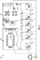
- FIG. 5 illustrates an example of an IoT environment (or distributed IoT network) 500 in accordance with an embodiment of the disclosure.
- the IoT environment 500 is an office space with a conference room 505, a plurality of offices 510 through 535 and a kitchen 540.
- various IoT devices can be deployed (e.g., a refrigerator, a coffee machine, etc.).
- different IoT devices with the same device type can be deployed.
- eight (8) different IoT "lamp" devices are shown as being deployed throughout the IoT environment 500 of FIG.
- IoT Lamp 1 being deployed in conference room 505, IoT Lamps 2...7 being deployed within offices 510...535, respectively, and IoT Lamp 8 being deployed in kitchen 540.
- IoT environment 500 of FIG. 5 is directed to an office, many other configurations of IoT environments are also possible (e.g., residential homes, retail stores, vehicles, stadiums, etc.).
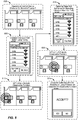
- FIG. 6 illustrates an example of a selection screen 600 that is based upon SSIDs detected for a set of IoT Lamps, such as IoT Lamps 1...8 from FIG. 5 .
- the operator of the control device can select a device from the list of WiFi hotspots via its associated SSID, after which the client devices sends a set of network credentials for the IoT network (e.g., a password, encryption information, frequency and/or channel information of an IoT communications interface upon which the IoT network operates, etc.) to the selected device.
- the selected device uses the IoT network credentials to join the IoT network.
- the SSID (or hotspot name) for a particular IoT device e.g., a phone, an appliance such as a lamp or coffee maker, etc.
- a manufacturer of the associated IoT device e.g., as shown in FIG.
- each of IoT Lamps 1...8 can be preconfigured with an SSID of "Lamp” that identifies each respective IoT device as having a "lamp” device-type without providing information by which the operator can easily differentiate between the respective IoT Lamps in the IoT environment 500.
- SSID of "Lamp” that identifies each respective IoT device as having a "lamp” device-type without providing information by which the operator can easily differentiate between the respective IoT Lamps in the IoT environment 500.
- the operator may have difficulty figuring out which of the listed IoT Lamps is the correct IoT Lamp to be on-boarded.
- FIG. 7 illustrates a process of on-boarding a device to a secure local network in accordance with an embodiment of the disclosure.
- the secure local network can correspond to an IoT network as described above, but it will be appreciated that the on-boarding procedure illustrated with respect to FIG. 7 can also be applied to non-IoT networks.
- the group of network-connected devices includes one or more network-connected devices plus at least one control device that is configured to selectively authorize new devices to join the secure local network (i.e., on-boarding).
- the at least one control device can be implemented as the supervisor device 130 described above in an example.
- the secure local network permits communications to occur via a secure network interface with an associated interface type (e.g., WiFi, Bluetooth, infrared (IR), LTE Direct, WiFi Direct, etc.).
- the one or more network-connected devices that are separate from the at least one control device can be considered optional in the case where a first device is being on-boarded to the secure local network.
- control device performing the on-boarding procedure in FIG. 7
- more than one control device could be used in other implementations.
- an operator could on-board new devices to the secure local network using a handset device, a laptop computer or a tablet computer at different times, such that different control devices can be used to on-board devices to the same secure local network in an example.
- data is exchanged between the group of network-connected devices over the secure network interface of the secure local network.
- devices 1...N enter into proximity with the secure local network, and announce their presence via one or more announce messages over a bootstrapping interface, 705 and 710.
- devices 1...N can each broadcast their respective SSID.
- the devices 1...N correspond to IoT Lamps 1...8 from FIG. 5
- the bootstrapping interface has an associated interface type (e.g., WiFi, Bluetooth, infrared (IR), LTE Direct, WiFi Direct, etc.) and is distinct from the secure local interface, although it is possible that the bootstrapping interface and the secure local interface share the same interface type.
- the secure local interface can be implemented as WiFi with a particular form of encryption, whereas the bootstrapping interface can correspond to unencrypted WiFi.
- the secure local interface and the bootstrapping interface are both "WiFi" in this example, it will be appreciated that the mere ability to communicate via WiFi does not permit devices to join the secure local network without knowledge of the encryption being used thereon.
- the interface types of the secure local interface and the bootstrapping interface can simply be different (e.g., the secure local network can use WiFi whereas the bootstrapping interface can use IR, Bluetooth, LTE Direct, WiFi Direct, etc.)
- the control device detects devices 1...N based on the announcements from 705 and 710, 715.
- the discovery procedure shown between 705-715 can be triggered by the control device broadcasting a discovery request in conjunction with a scan of the bootstrapping interface, whereby devices in proximity to the control device that are not yet part of the secure local network are expected to receive the discovery request and then announce their presence over the bootstrapping interface.
- the devices 1...N can transmit the announcements 705 and 710 on a periodic basis over the bootstrapping interface, so the control device merely needs to start scanning for nearby devices without broadcasting the discovery request.
- the control device obtains a selection of device 1 for on-boarding.
- device 1 does not necessarily correspond to the particular target device that the control device wishes to on-board to the secure local network, so the correlation (or lack thereof) between device 1 and the particular target device that the control device wishes to on-board to the secure local network must be verified, as will be described below in more detail.
- the selection of 720 can occur in a variety of ways.
- the operator of the control device can be presented with a list of discovered device as in FIG. 6 , from which the operator can input a selection of a device for an on-boarding attempt (e.g., by clicking on a particular IoT Lamp indicator).
- the operator of the control device can select a type of device that is desired to be on-boarded (e.g., lamp, television, dishwasher, etc.).
- the control device can then select a given device with the selected device type via a selection rule (e.g., a device that is not yet on-boarded with the selected device type having the highest associated signal strength over the bootstrapping interface, a random selection, a next device in a given sequence of devices determined by the control device based on selection criteria such as signal strength, etc.).
- a selection rule e.g., a device that is not yet on-boarded with the selected device type having the highest associated signal strength over the bootstrapping interface, a random selection, a next device in a given sequence of devices determined by the control device based on selection criteria such as signal strength, etc.
- the selected device for the on-boarding attempt is not simply on-boarded. Rather, as will be described below in more detail, the selected device first undergoes an authentication procedure by which the operator attempts to verify whether the selected device does, in fact, correspond to the physical device that the operator is trying to on-board to the secure local network.
- the control device establishes a bootstrap connection to device 1 via the bootstrapping interface, 725, and then delivers a message to device 1 over the bootstrap connection that requests the selected device to activate an observable function that is configured to be observable to one or more observation entities from a set of observation entities separate from the control device and in proximity to the selected device, 730.
- the observable function that is instructed to be activated via the message of 730 can be implemented in a variety of ways.
- the observable function can be a human-detectable indicator such as a visible indicator (e.g., a light or light sequence, etc.), an audible indicator (e.g., a beeping sound or other recognizable audio signature, etc.), a thermal indicator (e.g., heat, cold, etc.) or a mechanical indicator (e.g., vibration, movement, etc.).
- the observable function is expected to be capable of direct observation by a human (e.g., by the human's ears, nose, eyes, etc.), specifically, the operator of the control device, which permits the operator of the control device to personally verify that the device to be on-boarded is the correct device. So, if the operator is attempting to on-board his/her desk lamp to the secure local network, the desk lamp can emit a beep in an example. If the operator hears the beep, the operator can authorize on-boarding for the selected device.
- a human e.g., by the human's ears, nose, eyes, etc.
- the desk lamp can emit a beep in an example. If the operator hears the beep, the operator can authorize on-boarding for the selected device.
- the operator hears some other lamp emit the beep or a lamp that is outside of the range of the operator's hearing emits the beep, the operator will not authorize on-boarding for the selected device because the operator will realize that the selected device is not the correct device for on-boarding.
- the observable function can be a machine-detectable indicator that is not directly detectable by a human, such as an ultrasound, a short-range wireless signal, an infrared (IR) or ultraviolet emission, a thermal indicator that modifies heat and/or cold by less than a human detection threshold, a mechanical indicator (e.g., vibration, movement, etc., that is less than a human detection threshold).
- a human such as an ultrasound, a short-range wireless signal, an infrared (IR) or ultraviolet emission, a thermal indicator that modifies heat and/or cold by less than a human detection threshold, a mechanical indicator (e.g., vibration, movement, etc., that is less than a human detection threshold).
- the set of observation entities can include the operator of the control device him/herself.
- the set of observation entities could also include one or more machines that are configured to assist the operator of the control device to detect the observable function.
- the operator of the control device could listen for the beeping noise while the operator is holding a noise detector device (e.g., a microphone, etc.) that independently searches for the beeping noise.
- the set of observation entities can include the one or more machines configured to assist the operator of the control device to detect the observable function without the operator him/herself being included among the set of observation entities.
- the set of observation entities are generally considered to be separate from the control device itself.
- device 1 activates the observable function at 735, and the set of observation entities monitor for the observable function, 740.
- the control device determines whether the operator of the control device verifies that the observable function has been successfully detected as being performed by the particular target device for which on-boarding is desired. For example, the control device can present a prompt that asks the operator to verify whether or not the observable function was successfully detected as being performed by the particular target device for which on-boarding is desired.
- the control device does not authorize device 1 to access the secure local network and is not on-boarded, 750.
- the process can return to 720 whereby a different device is selected for the on-boarding attempt, either by manual operator selection or in accordance with a device sequence.
- the control device can define a sequence by which each of the eight IoT Lamps from FIG.
- the particular target IoT Lamp for which on-boarding is desired can then correspond to the IoT Lamp that is performing the observable function when the operator provides the verification at 745, while any other IoT Lamps remain unverified.
- the control device authorizes device 1 to access the secure local network, 755.
- the control device on-boards device 1 to the secure local network by transmitting a set of network credentials (e.g., a password, encryption information, frequency and/or channel information of an IoT communications interface upon which the IoT network operates, etc.) by which device 1 can join the secure local network to device 1 over the bootstrapping interface, 760, after which device 1 accesses the secure local network using the set of network credentials over the secure network interface, 765.
- a set of network credentials e.g., a password, encryption information, frequency and/or channel information of an IoT communications interface upon which the IoT network operates, etc.
- FIG. 8 illustrates a more detailed implementation of the process of FIG. 7 implemented in the IoT environment 500 of FIG. 5 in accordance with an embodiment of the disclosure.
- the operator of the control device wants to on-board IoT Lamp 5 from FIG. 5 within office 525 to the IoT network, 800.
- the operator may be an Information Technology (IT) administrator that is installing a new lamp into an office and wants the new lamp to comply with an energy saving control scheme, which requires the new lamp to be on-boarded to the IoT network.
- IT Information Technology
- the operator positions him/herself in proximity to IoT Lamp 5 within office 525 and then clicks on a first SSID "Lamp” entry (e.g., a top-listed SSID "Lamp” entry) on a selection screen of the control device as a result of a discovery procedure, 805 (e.g., similar to 705-720 of FIG. 7 ).
- a discovery procedure 805 (e.g., similar to 705-720 of FIG. 7 ).
- the first-selected SSID "Lamp” entry actually corresponds to IoT Lamp 4 instead of IoT Lamp 5, 810 (e.g., similar to 725-750 of FIG. 7 ).
- the operator does not verify the first SSID "Lamp” entry as corresponding to IoT Lamp 5, and instead the operator clicks on a next SSID "Lamp” entry (e.g., a second-from-the-top SSID "Lamp” entry, etc.) on the selection screen of the control device, 815 (e.g., similar to 705-720 of FIG. 7 ). Assume that the second-selected SSID "Lamp” entry corresponds to IoT Lamp 5, 820 (e.g., similar to 725-740 of FIG. 7 ).
- a next SSID "Lamp” entry e.g., a second-from-the-top SSID "Lamp” entry, etc.
- the operator verifies that the second-selected SSID "Lamp" entry corresponds to IoT Lamp 5, after which IoT Lamp 5 is on-boarded by the control device, 825 (e.g., similar to 745 and 755-765 of FIG. 7 ).
- DSP digital signal processor
- ASIC application specific integrated circuit
- FPGA field programmable gate array
- a general purpose processor may be a microprocessor, but in the alternative, the processor may be any conventional processor, controller, microcontroller, or state machine.
- a processor may also be implemented as a combination of computing devices (e.g., a combination of a DSP and a microprocessor, a plurality of microprocessors, one or more microprocessors in conjunction with a DSP core, or any other such configuration).
- a software module may reside in RAM, flash memory, ROM, EPROM, EEPROM, registers, hard disk, a removable disk, a CD-ROM, or any other form of storage medium known in the art.
- An exemplary storage medium is coupled to the processor such that the processor can read information from, and write information to, the storage medium.
- the storage medium may be integral to the processor.
- the processor and the storage medium may reside in an ASIC.
- the ASIC may reside in an IoT device.
- the processor and the storage medium may reside as discrete components in a user terminal.
- the functions described may be implemented in hardware, software, firmware, or any combination thereof. If implemented in software, the functions may be stored on or transmitted over as one or more instructions or code on a computer-readable medium.
- Computer-readable media includes both computer storage media and communication media including any medium that facilitates transfer of a computer program from one place to another.
- a storage media may be any available media that can be accessed by a computer.
- such computer-readable media can comprise RAM, ROM, EEPROM, CD-ROM or other optical disk storage, magnetic disk storage or other magnetic storage devices, or any other medium that can be used to carry or store desired program code in the form of instructions or data structures and that can be accessed by a computer.
- any connection is properly termed a computer-readable medium.
- the software is transmitted from a website, server, or other remote source using a coaxial cable, fiber optic cable, twisted pair, DSL, or wireless technologies such as infrared, radio, and microwave
- the coaxial cable, fiber optic cable, twisted pair, DSL, or wireless technologies such as infrared, radio, and microwave are included in the definition of medium.
- Disk and disc includes CD, laser disc, optical disc, DVD, floppy disk and Blu-ray disc where disks usually reproduce data magnetically and/or optically with lasers. Combinations of the above should also be included within the scope of computer-readable media.
Claims (14)
- Ein Verfahren zum Betreiben einer Steuereinrichtung, die konfiguriert ist zum selektiven An-Bord-Holen bzw. Eingliedern einer Zieleinrichtung in ein sicheres lokales Netzwerk, das Folgendes aufweist:Auffinden (715) eines Satzes von Einrichtungen (1....N) über eine Bootstrapping-Schnittstelle (705, 710);Einrichten (725) einer Bootstrap-Verbindung mit wenigstens einer Einrichtung (1) aus dem Satz von Einrichtungen ansprechend auf die Auffindung ohne Autorisieren der wenigstens einen Einrichtung auf das sichere lokale Netzwerk zuzugreifen;Anweisen (730) der wenigstens einen Einrichtung (1), welche der Zieleinrichtung entspricht, über die Bootstrap-Verbindung, eine beobachtbare Funktion zu aktivieren, die konfiguriert ist durch eine oder mehrere Beobachtungseinheiten beobachtbar zu sein, die von der Steuereinrichtung getrennt sind und sich in der Nähe der wenigstens einen Einrichtung (1) befinden;Bestimmen, durch die Steuereinrichtung (745), ob ein Betreiber der Steuereinrichtung verifiziert, dass erfolgreich detektiert worden ist, dass die beobachtbare Funktion durch die Zieleinrichtung durchgeführt wird; undselektives Autorisieren (755) der wenigstens einen Zieleinrichtung (1) auf das sichere lokale Netzwerk zuzugreifen basierend auf der Bestimmung.
- Verfahren nach Anspruch 1, wobei die eine oder die mehreren Beobachtungseinheiten Folgendes beinhalten: den Betreiber der Steuereinrichtung, eine oder mehrere Maschinen, die konfiguriert sind den Betreiber der Steuereinrichtung zu unterstützen die beobachtbare Funktion zu detektieren oder eine Kombination davon.
- Verfahren nach Anspruch 2, wobei die beobachtbare Funktion eine Ausgabe eines von einem Menschen detektierbaren Indikators, der konfiguriert ist, durch den Betreiber der Steuereinrichtung detektierbar zu sein, eines von einer Maschine detektierbaren Indikators, der konfiguriert ist durch eine oder mehrere Maschinen detektierbar zu sein, während er nicht direkt für den Betreiber der Steuereinrichtung detektierbar ist oder einer Kombination davon, beinhaltet.
- Verfahren nach Anspruch 1,
wobei die Bootstrapping-Schnittstelle WiFi, Bluetooth oder Infrarot bzw. IR aufweist, und
wobei das sichere lokale Netzwerk ein WiFi-Netzwerk ist. - Verfahren nach Anspruch 1, wobei die beobachtbare Funktion ein oder mehreres von einem sichtbaren Indikator, einem hörbaren Indikator, einem Ultraschall, einem Nahbereichsdrahtlossignal, einem nicht sichtbaren Indikator, einem Infrarot-Indikator, einem Ultraviolett-Indikator, einem thermischen Indikator oder mechanischen Indikator, einer Vibration, einer Bewegung oder irgendeine Kombination davon ist.
- Verfahren nach Anspruch 1, wobei der Betreiber der Steuereinrichtung verifiziert, dass erfolgreich detektiert worden ist, dass die beobachtbare Funktion durch die Zieleinrichtung durchgeführt wird, und
wobei das selektive Autorisieren die wenigstens eine Einrichtung autorisiert auf das sichere lokale Netzwerk ansprechend auf die Bestimmung zuzugreifen. - Verfahren nach Anspruch 6, das weiter Folgendes aufweist:
Senden eines Satzes von Netzwerkberechtigungsnachweisen an die wenigstens eine Einrichtung, der konfiguriert ist durch die wenigstens eine Einrichtung zum Zugreifen auf das sichere lokale Netzwerk verwendet zu werden. - Verfahren nach Anspruch 1,
wobei der Betreiber der Steuereinrichtung nicht verifiziert, dass erfolgreich detektiert worden ist, dass die beobachtbare Funktion durch die Zieleinrichtung durchgeführt wird, und
wobei das selektive Autorisieren die wenigstens eine Einrichtung nicht autorisiert, auf das sichere lokale Netzwerk zuzugreifen, und zwar ansprechend auf die Bestimmung. - Verfahren nach Anspruch 1,
wobei das sichere lokale Netzwerk ein Internet-of-Things- bzw. IoT-Netzwerk (500) ist, und
wobei die Zieleinrichtung eine IoT-Einrichtung ist. - Verfahren nach Anspruch 1, wobei die eine oder die mehreren Beobachtungseinheiten den Betreiber der Steuereinrichtung beinhalten.
- Verfahren nach Anspruch 10, wobei die beobachtbare Funktion eine Ausgabe eines von einem Menschen detektierbaren Indikators beinhaltet, der konfiguriert ist durch den Betreiber der Steuereinrichtung detektierbar zu sein.
- Ein Verfahren des Versuchen eine Einrichtung in ein sicheres lokales Netzwerk einzugliedern bzw. an Bord zu holen, das Folgendes aufweist:Einrichten (725), durch die Einrichtung, einer Bootstrap-Verbindung mit einer Steuereinrichtung des sicheren lokalen Netzwerkes ohne Erlangen von Autorisierung zum Zugreifen auf das sichere lokale Netzwerk;Empfangen, an der Einrichtung, einer Instruktion, über die Bootstrap-Verbindung, eine beobachtbare Funktion zu aktivieren, die konfiguriert ist durch eine oder mehrere Beobachtungseinheiten in der Nähe der Einrichtung beobachtbar zu sein;Aktivieren (732) der beobachtbaren Funktion ansprechend auf die Instruktion; undselektives Erlangen (765) von Autorisierung zum Zugreifen auf das sichere lokale Netzwerk basierend darauf, ob die Steuereinrichtung bestimmt, dass ein Betreiber der Steuereinrichtung erfolgreich detektiert, dass die beobachtbare Funktion durch die Einrichtung durchgeführt wird und verifiziert, dass die beobachtbare Funktion durch eine Zieleinrichtung durchgeführt wird, für welche eine Eingliederung erwünscht ist.
- Eine Steuereinrichtung, die konfiguriert ist zum selektiven Eingliedern bzw. An-Bord-Holen einer Zieleinrichtung in ein sicheres lokales Netzwerk, die Folgendes aufweist:Logik, die konfiguriert ist zum Auffinden eines Satzes von Einrichtungen über eine Bootstrapping-Schnittstelle;Logik, die konfiguriert ist zum Einrichten einer Bootstrap-Verbindung mit wenigstens einer Einrichtung aus dem Satz von Einrichtungen ansprechend auf die Auffindung ohne Autorisieren der wenigstens einen Einrichtung auf das sichere lokale Netzwerk zuzugreifen;Logik, die konfiguriert ist zum Anweisen der wenigstens einen Einrichtung, welche der Zieleinrichtung entspricht, über die Bootstrap-Verbindung eine beobachtbare Funktion zu aktivieren, die konfiguriert ist durch eine oder mehrere Beobachtungseinheiten beobachtet zu werden, die getrennt bzw. separat von der Steuereinrichtung sind und sich in der Nähe der wenigstens einen Einrichtung befinden;Logik, die konfiguriert ist zu bestimmen, ob ein Betreiber der Steuereinrichtung verifiziert, dass die beobachtbare Funktion erfolgreich als durch die Zieleinrichtung durchgeführt detektiert wird; undLogik, die konfiguriert ist zum selektiven Autorisieren der wenigstens einen Einrichtung auf das sichere lokale Netzwerk zuzugreifen basierend auf der Bestimmung.
- Ein System, das eine Einrichtung und eine Steuereinrichtung aufweist, wobei die Einrichtung konfiguriert ist zu versuchen einem sicheren lokalen Netzwerk beizutreten, wobei die Einrichtung Folgendes aufweist:Logik, die konfiguriert ist zum Einrichten einer Bootstrap-Verbindung mit der Steuereinrichtung des sicheren lokalen Netzwerkes ohne Erlangen einer Autorisierung auf das sichere lokale Netzwerk zuzugreifen;Logik, die konfiguriert ist zum Empfangen einer Instruktion über die Bootstrap-Verbindung zum Aktivieren einer beobachtbaren Funktion, die konfiguriert ist durch eine oder mehrere Beobachtungseinheiten in der Nähe der Einrichtung beobachtbar zu sein;Logik, die konfiguriert ist zum Aktivieren der beobachtbaren Funktion ansprechend auf die Instruktion; undLogik, die konfiguriert ist zum selektiven Erlangen einer Autorisierung auf das sichere lokale Netzwerk zuzugreifen basierend darauf, ob die Steuereinrichtung bestimmt, dass ein Betreiber der Steuereinrichtung erfolgreich detektiert, dass die beobachtbare Funktion durch die Einrichtung durchgeführt wird und verifiziert, dass die beobachtbare Funktion durch die Einrichtung durchgeführt wird, welche einer Zieleinrichtung entspricht, für welche ein Beitreten erwünscht ist.
Applications Claiming Priority (3)
| Application Number | Priority Date | Filing Date | Title |
|---|---|---|---|
| US201462031606P | 2014-07-31 | 2014-07-31 | |
| US14/803,461 US9699659B2 (en) | 2014-07-31 | 2015-07-20 | On-boarding a device to a secure local network |
| PCT/US2015/041542 WO2016018695A1 (en) | 2014-07-31 | 2015-07-22 | On-boarding a device to a secure local network |
Publications (2)
| Publication Number | Publication Date |
|---|---|
| EP3175641A1 EP3175641A1 (de) | 2017-06-07 |
| EP3175641B1 true EP3175641B1 (de) | 2019-05-15 |
Family
ID=55181265
Family Applications (1)
| Application Number | Title | Priority Date | Filing Date |
|---|---|---|---|
| EP15760531.2A Active EP3175641B1 (de) | 2014-07-31 | 2015-07-22 | On-boarding einer vorrichtung zu einem sicheren lokalen netzwerk |
Country Status (4)
| Country | Link |
|---|---|
| US (1) | US9699659B2 (de) |
| EP (1) | EP3175641B1 (de) |
| CN (1) | CN106576244B (de) |
| WO (1) | WO2016018695A1 (de) |
Families Citing this family (77)
| Publication number | Priority date | Publication date | Assignee | Title |
|---|---|---|---|---|
| US9226373B2 (en) | 2013-10-30 | 2015-12-29 | John Joseph King | Programmable light timer and a method of implementing a programmable light timer |
| WO2016064397A1 (en) * | 2014-10-23 | 2016-04-28 | Hewlett Packard Enterprise Development Lp | Admissions control of a device |
| WO2016068942A1 (en) | 2014-10-30 | 2016-05-06 | Hewlett Packard Enterprise Development Lp | Encryption for transactions in a memory fabric |
| US10699031B2 (en) | 2014-10-30 | 2020-06-30 | Hewlett Packard Enterprise Development Lp | Secure transactions in a memory fabric |
| US9774604B2 (en) | 2015-01-16 | 2017-09-26 | Zingbox, Ltd. | Private cloud control |
| US9730071B1 (en) * | 2015-03-05 | 2017-08-08 | Symantec Corporation | Systems and methods for connecting purpose-built appliances to secure wireless networks |
| US9974015B2 (en) * | 2015-07-03 | 2018-05-15 | Afero, Inc. | Embedded internet of things (IOT) hub for integration with an appliance and associated systems and methods |
| US9954956B2 (en) * | 2015-08-26 | 2018-04-24 | Intel IP Corporation | Secure discovery and connection to internet of things devices in a wireless local-area network |
| US20170149745A1 (en) * | 2015-11-19 | 2017-05-25 | Carrier Corporation | Wireless communication configuration device |
| US11095727B2 (en) * | 2015-12-22 | 2021-08-17 | Samsung Electronics Co., Ltd. | Electronic device and server for providing service related to internet of things device |
| US10834586B2 (en) * | 2016-07-29 | 2020-11-10 | Amzetta Technologies, Llc | System and method for controlling heterogeneous internet of things (IoT) devices using single application |
| FR3058540A1 (fr) * | 2016-11-10 | 2018-05-11 | Orange | Procede de gestion d'autorisation dans une communaute d'objets connectes |
| US10380348B2 (en) | 2016-11-21 | 2019-08-13 | ZingBox, Inc. | IoT device risk assessment |
| CN108667780B (zh) * | 2017-03-31 | 2021-05-14 | 华为技术有限公司 | 一种身份认证的方法、系统及服务器和终端 |
| US10996645B1 (en) | 2017-04-01 | 2021-05-04 | Smart Power Partners LLC | Modular power adapters and methods of implementing modular power adapters |
| US10727731B1 (en) | 2017-04-01 | 2020-07-28 | Smart Power Partners, LLC | Power adapters adapted to receive a module and methods of implementing power adapters with modules |
| US10530597B1 (en) | 2017-04-01 | 2020-01-07 | Smart Power Partners LLC | System for controlling a plurality of power switches configured to apply power to devices |
| US20180322592A1 (en) * | 2017-05-05 | 2018-11-08 | Dean Schiller | System and method for transferring service provider information |
| CA3072749A1 (en) * | 2017-09-26 | 2019-04-04 | Delaval Holding Ab | Control system, method and computer program for an automatic milking machine |
| US11070568B2 (en) | 2017-09-27 | 2021-07-20 | Palo Alto Networks, Inc. | IoT device management visualization |
| US11082296B2 (en) | 2017-10-27 | 2021-08-03 | Palo Alto Networks, Inc. | IoT device grouping and labeling |
| KR102400580B1 (ko) | 2018-01-22 | 2022-05-23 | 삼성전자주식회사 | 다른 전자 장치의 인증을 수행하는 전자 장치와 이의 동작 방법 |
| US10587400B2 (en) | 2018-02-12 | 2020-03-10 | Afero, Inc. | System and method for securely configuring a new device with network credentials |
| US11055658B2 (en) | 2018-02-23 | 2021-07-06 | Bank Of America Corporation | Blockchain-based supply chain certification systems and methods |
| US10609069B2 (en) | 2018-02-23 | 2020-03-31 | Bank Of America Corporation | Reflexive benign service attack on IoT device(s) |
| US10817829B2 (en) * | 2018-02-23 | 2020-10-27 | Bank Of America Corporation | Blockchain-based supply chain smart recall |
| US10498707B2 (en) | 2018-02-26 | 2019-12-03 | Bank Of America Corporation | IoT (“Internet of Things”) self-segmented blocks |
| US11122037B2 (en) | 2018-02-27 | 2021-09-14 | Bank Of America Corporation | Internet of things (“IoT”) protection retro-system |
| US10924480B2 (en) | 2018-02-28 | 2021-02-16 | Cisco Technology, Inc. | Extended trust for onboarding |
| US10700867B2 (en) | 2018-03-09 | 2020-06-30 | Bank Of America Corporation | Internet of things (“IoT”) multi-layered embedded handshake |
| US10721132B2 (en) | 2018-03-12 | 2020-07-21 | Bank Of America Corporation | IoT circuitry modules |
| US10574651B2 (en) | 2018-03-13 | 2020-02-25 | Bank Of America Corporation | Internet of things (“IoT”) chain link |
| US10645108B2 (en) | 2018-03-19 | 2020-05-05 | Bank Of America Corporation | Smart Internet of Things (“IoT”) web of trust |
| US10637873B2 (en) * | 2018-03-20 | 2020-04-28 | Bank Of America Corporation | Smart internet of things (“IOT”) relay monitors |
| US10819746B2 (en) | 2018-03-21 | 2020-10-27 | Bank Of America Corporation | Nodes on an internet of things (“IoT”) with dual-network access ports |
| DE102018204367A1 (de) * | 2018-03-22 | 2019-09-26 | Siemens Schweiz Ag | Verfahren und System zur Autorisierung der Kommunikation eines Netzwerkknotens |
| US10917293B2 (en) | 2018-03-25 | 2021-02-09 | Cisco Technology, Inc. | Controller for bulk onboarding |
| US10831914B2 (en) | 2018-03-26 | 2020-11-10 | Bank Of America Corporation | Secure extensible wireless communication with IoT devices |
| US10567390B2 (en) | 2018-03-26 | 2020-02-18 | Bank Of America Corporation | Peer to peer internet of things (“IoT”) validation system |
| US10848588B2 (en) | 2018-03-27 | 2020-11-24 | Bank Of America Corporation | Reverse proxy server for an internet of things (“IoT”) network |
| US11057462B2 (en) | 2018-03-27 | 2021-07-06 | Bank Of America Corporation | Asset management block chain |
| US10602930B2 (en) | 2018-03-29 | 2020-03-31 | Bank Of America Corporation | Multi-biometric-factor, internet of things (IOT), secured network |
| US10841303B2 (en) * | 2018-04-12 | 2020-11-17 | Bank Of America Corporation | Apparatus and methods for micro-segmentation of an enterprise internet-of-things network |
| EP3808052A4 (de) | 2018-06-18 | 2022-03-02 | Palo Alto Networks, Inc. | Musterübereinstimmungsbasierte erkennung in internet-der-dinge-sicherheit |
| US11604443B2 (en) * | 2018-08-23 | 2023-03-14 | Johnson Controls Tyco IP Holdings LLP | System and method for distributed device configuration and authorization |
| US11068598B2 (en) * | 2018-11-01 | 2021-07-20 | Dell Products L.P. | Chassis internal device security |
| US10949417B2 (en) | 2018-11-26 | 2021-03-16 | Bank Of America Corporation | Blockchain augmented internet of things (“IoT”) device-based system for dynamic supply chain tracking |
| US11451571B2 (en) | 2018-12-12 | 2022-09-20 | Palo Alto Networks, Inc. | IoT device risk assessment and scoring |
| KR20200074732A (ko) * | 2018-12-17 | 2020-06-25 | 삼성전자주식회사 | 전자 장치 및 전자 장치의 제어 방법 |
| US11689573B2 (en) | 2018-12-31 | 2023-06-27 | Palo Alto Networks, Inc. | Multi-layered policy management |
| US11171931B2 (en) | 2019-02-15 | 2021-11-09 | Wipro Limited | Method and system for providing a light-weight secure communication for computing devices |
| US10917956B1 (en) | 2019-06-30 | 2021-02-09 | Smart Power Partners LLC | Control attachment configured to provide power to a load and method of configuring a control attachment |
| US10958020B1 (en) | 2019-06-30 | 2021-03-23 | Smart Power Partners LLC | Control attachment for an in-wall power adapter and method of controlling an in-wall power adapter |
| US11264769B1 (en) | 2019-06-30 | 2022-03-01 | Smart Power Partners LLC | Power adapter having contact elements in a recess and method of controlling a power adapter |
| US10965068B1 (en) | 2019-06-30 | 2021-03-30 | Smart Power Partners LLC | In-wall power adapter having an outlet and method of controlling an in-wall power adapter |
| US11189948B1 (en) | 2019-06-30 | 2021-11-30 | Smart Power Partners LLC | Power adapter and method of implementing a power adapter to provide power to a load |
| US10938168B2 (en) | 2019-06-30 | 2021-03-02 | Smart Power Partners LLC | In-wall power adapter and method of controlling the application of power to a load |
| US11201444B1 (en) | 2019-06-30 | 2021-12-14 | Smart Power Partners LLC | Power adapter having contact elements in a recess and method of controlling a power adapter |
| US11043768B1 (en) | 2019-06-30 | 2021-06-22 | Smart Power Partners LLC | Power adapter configured to provide power to a load and method of implementing a power adapter |
| US11219108B1 (en) | 2019-06-30 | 2022-01-04 | Smart Power Partners LLC | Power adapter arrangement and method of implementing a power adapter arrangement |
| US10958026B1 (en) | 2019-06-30 | 2021-03-23 | Smart Power Partners LLC | Contactless thermometer for an in-wall power adapter |
| US11460874B1 (en) | 2019-06-30 | 2022-10-04 | Smart Power Partners LLC | In-wall power adapter configured to control the application of power to a load |
| US11579640B1 (en) | 2019-06-30 | 2023-02-14 | Smart Power Partners LLC | Control attachment for an in-wall power adapter |
| US11231730B1 (en) | 2019-06-30 | 2022-01-25 | Smart Power Power LLC | Control attachment for a power adapter configured to control power applied to a load |
| US10873983B1 (en) * | 2019-07-15 | 2020-12-22 | Verizon Patent And Licensing Inc. | Method and device for selecting a network mode for an internet of things device |
| US11165587B2 (en) | 2019-12-03 | 2021-11-02 | Bank Of America Corporation | System for authorizing resource requests based on cryptographic computations and federated hash verifications |
| FR3104309A1 (fr) * | 2019-12-04 | 2021-06-11 | Orange | Procédés d’authentification et d’intégration d’équipement utilisateur dans un système d’information, dispositifs et programmes d’ordinateurs correspondants. |
| US11436611B2 (en) | 2019-12-12 | 2022-09-06 | At&T Intellectual Property I, L.P. | Property archivist enabled customer service |
| EP3840441B1 (de) * | 2019-12-16 | 2023-10-18 | Axis AB | Verfahren zur herstellung einer sicheren drahtlosen verbindung |
| US11176505B2 (en) | 2020-01-07 | 2021-11-16 | Bank Of America Corporation | Multi-channel tracking and control system |
| US11539528B2 (en) | 2020-03-02 | 2022-12-27 | Bank Of America Corporation | System for authorizing secured access using cryptographic hash value validations |
| US11115799B1 (en) | 2020-06-01 | 2021-09-07 | Palo Alto Networks, Inc. | IoT device discovery and identification |
| CA3196131A1 (en) * | 2020-10-19 | 2022-04-28 | Sathish Arumugam Chandrasekaran | User friendly targeted methodology for satellite installation using mobile app |
| US11902273B2 (en) | 2021-03-30 | 2024-02-13 | Bank Of America Corporation | System for dynamic chaffing for log obfuscation based on shifting exposure portfolio |
| US11809448B2 (en) | 2021-04-19 | 2023-11-07 | Bank Of America Corporation | System for synchronizing dataflow migration between technical environments |
| US11552975B1 (en) | 2021-10-26 | 2023-01-10 | Palo Alto Networks, Inc. | IoT device identification with packet flow behavior machine learning model |
| US20230342163A1 (en) * | 2022-04-24 | 2023-10-26 | Vmware, Inc. | Distribution of bootstrap management for application monitoring |
Family Cites Families (11)
| Publication number | Priority date | Publication date | Assignee | Title |
|---|---|---|---|---|
| US7937089B2 (en) | 2002-02-06 | 2011-05-03 | Palo Alto Research Center Incorporated | Method, apparatus, and program product for provisioning secure wireless sensors |
| US8116889B2 (en) | 2002-06-27 | 2012-02-14 | Openpeak Inc. | Method, system, and computer program product for managing controlled residential or non-residential environments |
| US20040168081A1 (en) | 2003-02-20 | 2004-08-26 | Microsoft Corporation | Apparatus and method simplifying an encrypted network |
| US7930553B2 (en) * | 2003-04-11 | 2011-04-19 | Intel Corporation | System and method for extending secure authentication using unique session keys derived from entropy generated by authentication method |
| WO2006055986A2 (en) * | 2004-11-18 | 2006-05-26 | Azaire Networks Inc. | Service authorization in a wi-fi network interworked with 3g/gsm network |
| US9614964B2 (en) | 2005-08-19 | 2017-04-04 | Nextstep, Inc. | Consumer electronic registration, control and support concierge device and method |
| US7672671B2 (en) * | 2006-08-01 | 2010-03-02 | Motorola, Inc. | Method and apparatus for enabling operators with operators with unused bandwidth to acquire users |
| US8473325B2 (en) | 2007-10-12 | 2013-06-25 | Pie Digital, Inc. | System and method for automatic configuration and management of home network devices using a hierarchical index model |
| US8505078B2 (en) * | 2008-12-28 | 2013-08-06 | Qualcomm Incorporated | Apparatus and methods for providing authorized device access |
| US20140082702A1 (en) | 2012-09-19 | 2014-03-20 | Spark Devices | Systems and methods for controlling and communicating with connected devices |
| EP2936860B1 (de) * | 2012-12-19 | 2018-09-19 | Telefonaktiebolaget LM Ericsson (publ) | Anzeige der benutzergerätezugänglichkeit zur wi-fi-integration in einem ran |
-
2015
- 2015-07-20 US US14/803,461 patent/US9699659B2/en active Active
- 2015-07-22 CN CN201580041193.8A patent/CN106576244B/zh active Active
- 2015-07-22 EP EP15760531.2A patent/EP3175641B1/de active Active
- 2015-07-22 WO PCT/US2015/041542 patent/WO2016018695A1/en active Application Filing
Non-Patent Citations (1)
| Title |
|---|
| None * |
Also Published As
| Publication number | Publication date |
|---|---|
| WO2016018695A1 (en) | 2016-02-04 |
| US20160036819A1 (en) | 2016-02-04 |
| US9699659B2 (en) | 2017-07-04 |
| CN106576244B (zh) | 2020-04-24 |
| CN106576244A (zh) | 2017-04-19 |
| EP3175641A1 (de) | 2017-06-07 |
Similar Documents
| Publication | Publication Date | Title |
|---|---|---|
| EP3175641B1 (de) | On-boarding einer vorrichtung zu einem sicheren lokalen netzwerk | |
| US9596603B2 (en) | Distributed bulk onboarding process | |
| US9628691B2 (en) | Method and apparatus for identifying a physical IoT device | |
| AU2015301975B2 (en) | Method and apparatus for automatically generating an events dictionary in an Internet of Things (IoT) network | |
| US9584482B2 (en) | Access control lists for private networks of system agnostic connected devices | |
| US9185641B2 (en) | Using discoverable peer-to-peer services to allow remote onboarding of headless devices over a Wi-Fi network | |
| EP2959663B1 (de) | Steuerung vieler verschiedene vorrichtungen mithilfe einer intelligenten steuerungsvorrichtung | |
| EP3047616B1 (de) | Durch eine benutzeraktive anwendung aktiviertes gateway | |
| EP3146733B1 (de) | Auslösung von befehlen auf einer zielvorrichtung als antwort auf übertragene ereignisbenachrichtigungen | |
| US20150121470A1 (en) | Peer-to-peer onboarding of internet of things (iot) devices over various communication interfaces | |
| US20150071052A1 (en) | Reconfiguring a headless wireless device | |
| JP6622716B2 (ja) | ユーザプリファレンスまたはデバイス構成を設定するための方法および装置 | |
| US20150071216A1 (en) | Allowing mass re-onboarding of headless devices | |
| EP3014427A1 (de) | Semantische abbildungen von für menschen lesbaren informationen an programmierschnittstellen | |
| KR20150121091A (ko) | 이종의 사물 인터넷 (IoT) 디바이스들에 대한 적응적이고 확장가능한 범용 스키마 | |
| EP3152882B1 (de) | Bestimmung des vertrauensniveaus auf einer vorrichtung mit empfang einer autorisierung |
Legal Events
| Date | Code | Title | Description |
|---|---|---|---|
| STAA | Information on the status of an ep patent application or granted ep patent |
Free format text: STATUS: THE INTERNATIONAL PUBLICATION HAS BEEN MADE |
|
| 17P | Request for examination filed |
Effective date: 20161214 |
|
| AK | Designated contracting states |
Kind code of ref document: A1 Designated state(s): AL AT BE BG CH CY CZ DE DK EE ES FI FR GB GR HR HU IE IS IT LI LT LU LV MC MK MT NL NO PL PT RO RS SE SI SK SM TR |
|
| AX | Request for extension of the european patent |
Extension state: BA ME |
|
| PUAI | Public reference made under article 153(3) epc to a published international application that has entered the european phase |
Free format text: ORIGINAL CODE: 0009012 |
|
| STAA | Information on the status of an ep patent application or granted ep patent |
Free format text: STATUS: REQUEST FOR EXAMINATION WAS MADE |
|
| DAV | Request for validation of the european patent (deleted) | ||
| DAX | Request for extension of the european patent (deleted) | ||
| RIC1 | Information provided on ipc code assigned before grant |
Ipc: H04W 12/08 20090101AFI20181128BHEP Ipc: H04W 48/08 20090101ALI20181128BHEP Ipc: G06F 9/4401 20180101ALI20181128BHEP Ipc: H04L 29/08 20060101ALI20181128BHEP Ipc: H04W 12/06 20090101ALI20181128BHEP Ipc: H04W 4/70 20180101ALI20181128BHEP Ipc: H04W 48/04 20090101ALI20181128BHEP Ipc: H04W 8/00 20090101ALI20181128BHEP |
|
| GRAP | Despatch of communication of intention to grant a patent |
Free format text: ORIGINAL CODE: EPIDOSNIGR1 |
|
| STAA | Information on the status of an ep patent application or granted ep patent |
Free format text: STATUS: GRANT OF PATENT IS INTENDED |
|
| INTG | Intention to grant announced |
Effective date: 20190107 |
|
| RIC1 | Information provided on ipc code assigned before grant |
Ipc: G06F 9/4401 20180101ALI20181128BHEP Ipc: H04L 29/08 20060101ALI20181128BHEP Ipc: H04W 48/04 20090101ALI20181128BHEP Ipc: H04W 12/08 20090101AFI20181128BHEP Ipc: H04W 8/00 20090101ALI20181128BHEP Ipc: H04W 48/08 20090101ALI20181128BHEP Ipc: H04W 12/06 20090101ALI20181128BHEP Ipc: H04W 4/70 20180101ALI20181128BHEP |
|
| GRAS | Grant fee paid |
Free format text: ORIGINAL CODE: EPIDOSNIGR3 |
|
| GRAA | (expected) grant |
Free format text: ORIGINAL CODE: 0009210 |
|
| STAA | Information on the status of an ep patent application or granted ep patent |
Free format text: STATUS: THE PATENT HAS BEEN GRANTED |
|
| AK | Designated contracting states |
Kind code of ref document: B1 Designated state(s): AL AT BE BG CH CY CZ DE DK EE ES FI FR GB GR HR HU IE IS IT LI LT LU LV MC MK MT NL NO PL PT RO RS SE SI SK SM TR |
|
| REG | Reference to a national code |
Ref country code: CH Ref legal event code: EP |
|
| REG | Reference to a national code |
Ref country code: DE Ref legal event code: R096 Ref document number: 602015030382 Country of ref document: DE |
|
| REG | Reference to a national code |
Ref country code: IE Ref legal event code: FG4D |
|
| REG | Reference to a national code |
Ref country code: NL Ref legal event code: FP |
|
| REG | Reference to a national code |
Ref country code: LT Ref legal event code: MG4D |
|
| PG25 | Lapsed in a contracting state [announced via postgrant information from national office to epo] |
Ref country code: HR Free format text: LAPSE BECAUSE OF FAILURE TO SUBMIT A TRANSLATION OF THE DESCRIPTION OR TO PAY THE FEE WITHIN THE PRESCRIBED TIME-LIMIT Effective date: 20190515 Ref country code: LT Free format text: LAPSE BECAUSE OF FAILURE TO SUBMIT A TRANSLATION OF THE DESCRIPTION OR TO PAY THE FEE WITHIN THE PRESCRIBED TIME-LIMIT Effective date: 20190515 Ref country code: FI Free format text: LAPSE BECAUSE OF FAILURE TO SUBMIT A TRANSLATION OF THE DESCRIPTION OR TO PAY THE FEE WITHIN THE PRESCRIBED TIME-LIMIT Effective date: 20190515 Ref country code: AL Free format text: LAPSE BECAUSE OF FAILURE TO SUBMIT A TRANSLATION OF THE DESCRIPTION OR TO PAY THE FEE WITHIN THE PRESCRIBED TIME-LIMIT Effective date: 20190515 Ref country code: NO Free format text: LAPSE BECAUSE OF FAILURE TO SUBMIT A TRANSLATION OF THE DESCRIPTION OR TO PAY THE FEE WITHIN THE PRESCRIBED TIME-LIMIT Effective date: 20190815 Ref country code: SE Free format text: LAPSE BECAUSE OF FAILURE TO SUBMIT A TRANSLATION OF THE DESCRIPTION OR TO PAY THE FEE WITHIN THE PRESCRIBED TIME-LIMIT Effective date: 20190515 Ref country code: PT Free format text: LAPSE BECAUSE OF FAILURE TO SUBMIT A TRANSLATION OF THE DESCRIPTION OR TO PAY THE FEE WITHIN THE PRESCRIBED TIME-LIMIT Effective date: 20190915 |
|
| PG25 | Lapsed in a contracting state [announced via postgrant information from national office to epo] |
Ref country code: LV Free format text: LAPSE BECAUSE OF FAILURE TO SUBMIT A TRANSLATION OF THE DESCRIPTION OR TO PAY THE FEE WITHIN THE PRESCRIBED TIME-LIMIT Effective date: 20190515 Ref country code: GR Free format text: LAPSE BECAUSE OF FAILURE TO SUBMIT A TRANSLATION OF THE DESCRIPTION OR TO PAY THE FEE WITHIN THE PRESCRIBED TIME-LIMIT Effective date: 20190816 Ref country code: BG Free format text: LAPSE BECAUSE OF FAILURE TO SUBMIT A TRANSLATION OF THE DESCRIPTION OR TO PAY THE FEE WITHIN THE PRESCRIBED TIME-LIMIT Effective date: 20190815 Ref country code: RS Free format text: LAPSE BECAUSE OF FAILURE TO SUBMIT A TRANSLATION OF THE DESCRIPTION OR TO PAY THE FEE WITHIN THE PRESCRIBED TIME-LIMIT Effective date: 20190515 |
|
| REG | Reference to a national code |
Ref country code: AT Ref legal event code: MK05 Ref document number: 1134834 Country of ref document: AT Kind code of ref document: T Effective date: 20190515 |
|
| PG25 | Lapsed in a contracting state [announced via postgrant information from national office to epo] |
Ref country code: CZ Free format text: LAPSE BECAUSE OF FAILURE TO SUBMIT A TRANSLATION OF THE DESCRIPTION OR TO PAY THE FEE WITHIN THE PRESCRIBED TIME-LIMIT Effective date: 20190515 Ref country code: EE Free format text: LAPSE BECAUSE OF FAILURE TO SUBMIT A TRANSLATION OF THE DESCRIPTION OR TO PAY THE FEE WITHIN THE PRESCRIBED TIME-LIMIT Effective date: 20190515 Ref country code: SK Free format text: LAPSE BECAUSE OF FAILURE TO SUBMIT A TRANSLATION OF THE DESCRIPTION OR TO PAY THE FEE WITHIN THE PRESCRIBED TIME-LIMIT Effective date: 20190515 Ref country code: AT Free format text: LAPSE BECAUSE OF FAILURE TO SUBMIT A TRANSLATION OF THE DESCRIPTION OR TO PAY THE FEE WITHIN THE PRESCRIBED TIME-LIMIT Effective date: 20190515 Ref country code: DK Free format text: LAPSE BECAUSE OF FAILURE TO SUBMIT A TRANSLATION OF THE DESCRIPTION OR TO PAY THE FEE WITHIN THE PRESCRIBED TIME-LIMIT Effective date: 20190515 |
|
| REG | Reference to a national code |
Ref country code: DE Ref legal event code: R097 Ref document number: 602015030382 Country of ref document: DE |
|
| PG25 | Lapsed in a contracting state [announced via postgrant information from national office to epo] |
Ref country code: IT Free format text: LAPSE BECAUSE OF FAILURE TO SUBMIT A TRANSLATION OF THE DESCRIPTION OR TO PAY THE FEE WITHIN THE PRESCRIBED TIME-LIMIT Effective date: 20190515 Ref country code: SM Free format text: LAPSE BECAUSE OF FAILURE TO SUBMIT A TRANSLATION OF THE DESCRIPTION OR TO PAY THE FEE WITHIN THE PRESCRIBED TIME-LIMIT Effective date: 20190515 Ref country code: MC Free format text: LAPSE BECAUSE OF FAILURE TO SUBMIT A TRANSLATION OF THE DESCRIPTION OR TO PAY THE FEE WITHIN THE PRESCRIBED TIME-LIMIT Effective date: 20190515 |
|
| REG | Reference to a national code |
Ref country code: CH Ref legal event code: PL |
|
| PLBE | No opposition filed within time limit |
Free format text: ORIGINAL CODE: 0009261 |
|
| STAA | Information on the status of an ep patent application or granted ep patent |
Free format text: STATUS: NO OPPOSITION FILED WITHIN TIME LIMIT |
|
| PG25 | Lapsed in a contracting state [announced via postgrant information from national office to epo] |
Ref country code: TR Free format text: LAPSE BECAUSE OF FAILURE TO SUBMIT A TRANSLATION OF THE DESCRIPTION OR TO PAY THE FEE WITHIN THE PRESCRIBED TIME-LIMIT Effective date: 20190515 |
|
| REG | Reference to a national code |
Ref country code: BE Ref legal event code: MM Effective date: 20190731 |
|
| 26N | No opposition filed |
Effective date: 20200218 |
|
| PG25 | Lapsed in a contracting state [announced via postgrant information from national office to epo] |
Ref country code: PL Free format text: LAPSE BECAUSE OF FAILURE TO SUBMIT A TRANSLATION OF THE DESCRIPTION OR TO PAY THE FEE WITHIN THE PRESCRIBED TIME-LIMIT Effective date: 20190515 |
|
| PG25 | Lapsed in a contracting state [announced via postgrant information from national office to epo] |
Ref country code: CH Free format text: LAPSE BECAUSE OF NON-PAYMENT OF DUE FEES Effective date: 20190731 Ref country code: BE Free format text: LAPSE BECAUSE OF NON-PAYMENT OF DUE FEES Effective date: 20190731 Ref country code: LI Free format text: LAPSE BECAUSE OF NON-PAYMENT OF DUE FEES Effective date: 20190731 Ref country code: LU Free format text: LAPSE BECAUSE OF NON-PAYMENT OF DUE FEES Effective date: 20190722 Ref country code: SI Free format text: LAPSE BECAUSE OF FAILURE TO SUBMIT A TRANSLATION OF THE DESCRIPTION OR TO PAY THE FEE WITHIN THE PRESCRIBED TIME-LIMIT Effective date: 20190515 |
|
| PG25 | Lapsed in a contracting state [announced via postgrant information from national office to epo] |
Ref country code: IE Free format text: LAPSE BECAUSE OF NON-PAYMENT OF DUE FEES Effective date: 20190722 |
|
| PG25 | Lapsed in a contracting state [announced via postgrant information from national office to epo] |
Ref country code: ES Free format text: LAPSE BECAUSE OF FAILURE TO SUBMIT A TRANSLATION OF THE DESCRIPTION OR TO PAY THE FEE WITHIN THE PRESCRIBED TIME-LIMIT Effective date: 20190515 |
|
| PG25 | Lapsed in a contracting state [announced via postgrant information from national office to epo] |
Ref country code: RO Free format text: LAPSE BECAUSE OF FAILURE TO SUBMIT A TRANSLATION OF THE DESCRIPTION OR TO PAY THE FEE WITHIN THE PRESCRIBED TIME-LIMIT Effective date: 20190515 |
|
| PG25 | Lapsed in a contracting state [announced via postgrant information from national office to epo] |
Ref country code: CY Free format text: LAPSE BECAUSE OF FAILURE TO SUBMIT A TRANSLATION OF THE DESCRIPTION OR TO PAY THE FEE WITHIN THE PRESCRIBED TIME-LIMIT Effective date: 20190515 |
|
| PG25 | Lapsed in a contracting state [announced via postgrant information from national office to epo] |
Ref country code: IS Free format text: LAPSE BECAUSE OF FAILURE TO SUBMIT A TRANSLATION OF THE DESCRIPTION OR TO PAY THE FEE WITHIN THE PRESCRIBED TIME-LIMIT Effective date: 20190915 |
|
| PG25 | Lapsed in a contracting state [announced via postgrant information from national office to epo] |
Ref country code: HU Free format text: LAPSE BECAUSE OF FAILURE TO SUBMIT A TRANSLATION OF THE DESCRIPTION OR TO PAY THE FEE WITHIN THE PRESCRIBED TIME-LIMIT; INVALID AB INITIO Effective date: 20150722 Ref country code: MT Free format text: LAPSE BECAUSE OF FAILURE TO SUBMIT A TRANSLATION OF THE DESCRIPTION OR TO PAY THE FEE WITHIN THE PRESCRIBED TIME-LIMIT Effective date: 20190515 |
|
| PG25 | Lapsed in a contracting state [announced via postgrant information from national office to epo] |
Ref country code: MK Free format text: LAPSE BECAUSE OF FAILURE TO SUBMIT A TRANSLATION OF THE DESCRIPTION OR TO PAY THE FEE WITHIN THE PRESCRIBED TIME-LIMIT Effective date: 20190515 |
|
| PGFP | Annual fee paid to national office [announced via postgrant information from national office to epo] |
Ref country code: NL Payment date: 20230619 Year of fee payment: 9 Ref country code: FR Payment date: 20230616 Year of fee payment: 9 |
|
| PGFP | Annual fee paid to national office [announced via postgrant information from national office to epo] |
Ref country code: GB Payment date: 20230614 Year of fee payment: 9 |
|
| PGFP | Annual fee paid to national office [announced via postgrant information from national office to epo] |
Ref country code: DE Payment date: 20230614 Year of fee payment: 9 |