EP3175134B1 - Disc brake caliper employing a spring to influence pads acting on the disc of the disc brake - Google Patents
Disc brake caliper employing a spring to influence pads acting on the disc of the disc brake Download PDFInfo
- Publication number
- EP3175134B1 EP3175134B1 EP15753465.2A EP15753465A EP3175134B1 EP 3175134 B1 EP3175134 B1 EP 3175134B1 EP 15753465 A EP15753465 A EP 15753465A EP 3175134 B1 EP3175134 B1 EP 3175134B1
- Authority
- EP
- European Patent Office
- Prior art keywords
- pads
- disc
- spring
- caliper
- disc brake
- Prior art date
- Legal status (The legal status is an assumption and is not a legal conclusion. Google has not performed a legal analysis and makes no representation as to the accuracy of the status listed.)
- Not-in-force
Links
Images
Classifications
-
- F—MECHANICAL ENGINEERING; LIGHTING; HEATING; WEAPONS; BLASTING
- F16—ENGINEERING ELEMENTS AND UNITS; GENERAL MEASURES FOR PRODUCING AND MAINTAINING EFFECTIVE FUNCTIONING OF MACHINES OR INSTALLATIONS; THERMAL INSULATION IN GENERAL
- F16D—COUPLINGS FOR TRANSMITTING ROTATION; CLUTCHES; BRAKES
- F16D65/00—Parts or details
- F16D65/02—Braking members; Mounting thereof
- F16D65/04—Bands, shoes or pads; Pivots or supporting members therefor
- F16D65/092—Bands, shoes or pads; Pivots or supporting members therefor for axially-engaging brakes, e.g. disc brakes
- F16D65/095—Pivots or supporting members therefor
- F16D65/097—Resilient means interposed between pads and supporting members or other brake parts
- F16D65/0973—Resilient means interposed between pads and supporting members or other brake parts not subjected to brake forces
- F16D65/0974—Resilient means interposed between pads and supporting members or other brake parts not subjected to brake forces acting on or in the vicinity of the pad rim in a direction substantially transverse to the brake disc axis
- F16D65/0977—Springs made from sheet metal
-
- F—MECHANICAL ENGINEERING; LIGHTING; HEATING; WEAPONS; BLASTING
- F16—ENGINEERING ELEMENTS AND UNITS; GENERAL MEASURES FOR PRODUCING AND MAINTAINING EFFECTIVE FUNCTIONING OF MACHINES OR INSTALLATIONS; THERMAL INSULATION IN GENERAL
- F16D—COUPLINGS FOR TRANSMITTING ROTATION; CLUTCHES; BRAKES
- F16D55/00—Brakes with substantially-radial braking surfaces pressed together in axial direction, e.g. disc brakes
- F16D55/02—Brakes with substantially-radial braking surfaces pressed together in axial direction, e.g. disc brakes with axially-movable discs or pads pressed against axially-located rotating members
- F16D55/22—Brakes with substantially-radial braking surfaces pressed together in axial direction, e.g. disc brakes with axially-movable discs or pads pressed against axially-located rotating members by clamping an axially-located rotating disc between movable braking members, e.g. movable brake discs or brake pads
- F16D55/224—Brakes with substantially-radial braking surfaces pressed together in axial direction, e.g. disc brakes with axially-movable discs or pads pressed against axially-located rotating members by clamping an axially-located rotating disc between movable braking members, e.g. movable brake discs or brake pads with a common actuating member for the braking members
- F16D55/225—Brakes with substantially-radial braking surfaces pressed together in axial direction, e.g. disc brakes with axially-movable discs or pads pressed against axially-located rotating members by clamping an axially-located rotating disc between movable braking members, e.g. movable brake discs or brake pads with a common actuating member for the braking members the braking members being brake pads
-
- F—MECHANICAL ENGINEERING; LIGHTING; HEATING; WEAPONS; BLASTING
- F16—ENGINEERING ELEMENTS AND UNITS; GENERAL MEASURES FOR PRODUCING AND MAINTAINING EFFECTIVE FUNCTIONING OF MACHINES OR INSTALLATIONS; THERMAL INSULATION IN GENERAL
- F16D—COUPLINGS FOR TRANSMITTING ROTATION; CLUTCHES; BRAKES
- F16D65/00—Parts or details
- F16D65/005—Components of axially engaging brakes not otherwise provided for
- F16D65/0068—Brake calipers
-
- F—MECHANICAL ENGINEERING; LIGHTING; HEATING; WEAPONS; BLASTING
- F16—ENGINEERING ELEMENTS AND UNITS; GENERAL MEASURES FOR PRODUCING AND MAINTAINING EFFECTIVE FUNCTIONING OF MACHINES OR INSTALLATIONS; THERMAL INSULATION IN GENERAL
- F16D—COUPLINGS FOR TRANSMITTING ROTATION; CLUTCHES; BRAKES
- F16D55/00—Brakes with substantially-radial braking surfaces pressed together in axial direction, e.g. disc brakes
- F16D2055/0004—Parts or details of disc brakes
- F16D2055/0016—Brake calipers
-
- F—MECHANICAL ENGINEERING; LIGHTING; HEATING; WEAPONS; BLASTING
- F16—ENGINEERING ELEMENTS AND UNITS; GENERAL MEASURES FOR PRODUCING AND MAINTAINING EFFECTIVE FUNCTIONING OF MACHINES OR INSTALLATIONS; THERMAL INSULATION IN GENERAL
- F16D—COUPLINGS FOR TRANSMITTING ROTATION; CLUTCHES; BRAKES
- F16D55/00—Brakes with substantially-radial braking surfaces pressed together in axial direction, e.g. disc brakes
- F16D2055/0004—Parts or details of disc brakes
- F16D2055/0041—Resilient elements interposed directly between the actuating member and the brake support, e.g. anti-rattle springs
-
- F—MECHANICAL ENGINEERING; LIGHTING; HEATING; WEAPONS; BLASTING
- F16—ENGINEERING ELEMENTS AND UNITS; GENERAL MEASURES FOR PRODUCING AND MAINTAINING EFFECTIVE FUNCTIONING OF MACHINES OR INSTALLATIONS; THERMAL INSULATION IN GENERAL
- F16D—COUPLINGS FOR TRANSMITTING ROTATION; CLUTCHES; BRAKES
- F16D55/00—Brakes with substantially-radial braking surfaces pressed together in axial direction, e.g. disc brakes
- F16D2055/0004—Parts or details of disc brakes
- F16D2055/007—Pins holding the braking members
Definitions
- the present invention relates to a disc brake caliper, particularly a caliper employing a spring to influence pads acting on the disc of the disc brake.
- disc brake calipers comprise pads adapted to be pressed by one or more pistons against the braking band of the associable brake disc during a braking step.
- the pads comprise support plates each having a first side on which the pistons act and an opposite second side adapted to be pressed against the braking band of the brake disc.
- the pads comprise a friction material connected on such a second side of the support plates.
- the pistons cease exerting the thrust action; nevertheless, the pad in contact with the braking band tends to remain in position, thus generating a residual braking torque and also bothersome noise and a perceptible vibration at the steering wheel.
- the plates of the pads are hung to the calipers by means of pins by means of respective suspension slots obtained in the plate.
- Such known calipers also comprise springs adapted to act between the pins and the pads to influence the pads both away from the pins, that is to hold the pads elastically in a "lowered" position, and away from the braking surfaces of the disc.
- these calipers fitted with springs of known type do not ensure a correct positioning of the plate during the braking release step.
- the spring elastically pushes the plate in axial direction away from the brake disc up to the point that the first side of the plate is positioned excessively in the vicinity of an inner wall of the caliper or, if necessary, comes in contact with such an inner wall.
- Such positioning of the plate can generate bothersome vibrations of the plate against the inner wall of the caliper.
- An example of a state of the art pad spring is shown in FR 2508128 A1 .
- a disc brake caliper particularly a caliper employing springs to influence pads acting on the disc of the disc brake, in accordance with claim 1.
- such a disc brake caliper comprises:
- said first means for influencing the pads comprise a curved portion shaped as a hook distal from the central base portion of the leaf spring
- said second means for influencing the pads comprise a portion of wing folded away from said surface of the wing, said folded portion of wing having a first edge constrained to the wing in the vicinity of said curved portion and an opposite second free edge projecting towards the disc of the disc brake.
- said folded portion of wing projects towards the disc of the disc brake while remaining substantially rectilinear.
- said longitudinal beam of the spring comprises a first half-beam comprising said first end adapted to be removably constrained to the first/second connection bridge of the caliper body, said first end of the longitudinal beam comprises an L-shaped engagement portion connected to an inclined surface of the first half-beam which projects from the central base of the spring.
- said longitudinal beam of the spring comprises a second half-beam comprising said second end shaped to removably constrain the longitudinal beam to the first/second end bridge of the caliper body, said second end of the longitudinal beam comprises a claw adapted to be inserted in a respective slot made in the first/second end bridge.
- said spring further comprises a leaf element having a respective first end portion mechanically constrained to the central base portion of the spring, said leaf element comprises a second, curved end portion opposite to the aforesaid first end portion in sliding contact on the inclined surface of the first half-beam.
- said leaf element comprises an arched intermediate portion between said first and second end portion, said leaf element is configured to increase the elastic resistance of the first half-beam of the longitudinal beam with respect to the one of the second half-beam.
- said central base portion of the spring lies substantially on a base plane defining an axial axis lying on the plane substantially coincident with the axial direction parallel to the rotation axis of the disc, said cross beam of the spring includes a first and an opposite second branch influencing the pads connected to a first base edge portion of the central base portion of the spring and an opposite second base edge portion of said central base portion, respectively, each of said branches influencing the pads comprises a folded portion of the branch which is positioned transversely to the plane on which the central base portion lies and which is connected to the respective wing.
- said wings of the spring lie on a first plane inclined with respect to the plane on which the central base portion lies.
- 100 globally indicates a disc brake caliper, comprising a caliper body 10 positioned astride a disc of the disc brake (not shown).
- a caliper body 10 is fitted with a pair of half-bodies 11, 12 connected to each other by means of a first 20 and a second 21 end bridge of the half-bodies 11, 12 to delimit a central aperture 22 of the caliper body 10.
- the caliper body 10 comprises a first 13 and a second 14 connection bridge placed astride the disc of the disc brake at such a central aperture 22.
- the caliper body 10 can be of the monoblock type, in which the half-bodies 11, 12 are a single piece with each other, or the half-bodies 11, 12 can be joined mechanically to each other, for example by means of threaded connection means.
- the caliper body 10 is configured to delimit a compartment 15 for accommodating brake pads 2, 3 supported by said caliper body 10 by means of respective suspension pins for pads 4, 4', 5, 5'.
- the caliper body 10 comprises first suspension pins 4, 4' and second suspension pins 5, 5' of the pads.
- the pads 2, 3 are hung to the caliper body 10 by means of the aforesaid pins by means of respective suspension slots (not shown) obtained in the plates of the pads.
- the half-bodies 11, 12 of the caliper body 10 are arranged on opposite sides with respect to the housing compartment 15 in an axial direction X-X parallel to the rotation axis of the associable brake disc.
- the brake disc has two opposite friction surfaces (not shown in the drawings) against which the opposite brake pads 2, 3 accommodated in compartment 15 of the caliper body 10 abut during the braking action.
- the plates of the pads 2, 3 each include a first side 42 facing the disc of the disc brake, connected to an opposite second side 44 by means of a corner 43 facing the above-mentioned central aperture 22.
- Such a second side 44 of pad 2, 3 faces an inner wall 90 of the half-bodies 11, 12.
- caliper 100 comprises a first 50 and a second 51 leaf spring, for example cross-shaped, to influence the pads 2, 3 in said axial direction X-X.
- first leaf spring 50 is adapted to act between the pads 2, 3 and between the first connection bridge 13 and the first end bridge 20 of the half-bodies 11, 12.
- the second leaf spring 51 is adapted to act between the pads 2, 3 and between the second connection bridge 14 and the second end bridge 21 of the half-bodies 11, 12.
- the first leaf spring 50 is adapted to act on a first portion of the pads 2, 3 at the first suspension pins 4, 4', that is the portion of the pads with which the latter are suspended to the first pins 4, 4'.
- the second leaf spring 51 is adapted to act on a second portion of the pads 2, 3 at the second suspension pins 5, 5', that is the portion of the pads with which the latter are suspended to the second pins 5, 5'.
- the aforesaid leaf springs 50, 51 are structurally equal.
- such a leaf spring 50 comprises a spring body 60 made by means of cross junction of a first beam or bow-shaped longitudinal beam 61 and of a second beam or shaped cross beam 62.
- first and second beams 61, 62 are connected mechanically to each other at a central portion of spring 50, for example by means of a threaded connection means.
- the above-mentioned cross beam 62 of the leaf spring 50 is connected to the longitudinal beam 61 at a central base portion 64 of the spring or central base.
- Such a longitudinal beam 61 comprises a first 61a and a second 61b half-beam.
- the first half-beam 61a comprises a shaped first end 73 of the longitudinal beam 61 adapted to be removably constrained to the first connection bridge 13.
- a first end 73 comprises an L-shaped engagement portion, connected to an inclined surface 61c of the first half-beam 61a which projects from the central base 64 of spring 50.
- the L-shaped engagement portion 73 is adapted to be inserted below the first connection bridge 13 at a chamfer 73' obtained in such a connection bridge.
- the second half-beam 61b of the longitudinal beam 61 is substantially S-shaped and is fitted with a shaped second end 74 opposite to such a first end 73 to removably constrain the longitudinal beam 61 to the first end bridge 20.
- a shaped second end materializes in a claw 74 adapted to be inserted in a slot (not shown) obtained in the first end bridge 20.
- the aforesaid longitudinal bow-beam 61 constrained to the first connection bridge 13 and to the first end bridge 20 is adapted to arch in direction orthogonal to the axial direction X-X away from the disc to discharge on the latter the vertical stresses countering the movements of the pads 2, 3.
- the body of spring 60 further comprises a leaf element 63 constrained mechanically to the aforesaid first and second beams 61, 62 at the central base portion 64 by means of a respective first end portion 63'.
- a leaf element 63 comprises a second, curved end portion 63a opposite to the aforesaid first portion 63' in sliding contact on the inclined surface 61c of the first half-beam 61a, for damping the vibrations of the pads generated during the braking steps and therefore for reducing the noisiness of the brake.
- a leaf element 63 comprises an arched intermediate portion 63b between the first 63' and the second 63a end portion adapted to give elasticity to the element.
- the leaf element 63 is configured to increase the rigidity (that is to say, the elastic resistance) of the first half-beam 61a with respect to the rigidity of the second half-beam 61b.
- the reduced rigidity of the second half-beam 61b allows easier positioning and easier manual deformation of spring 50.
- the cross beam 62 of the above-mentioned spring 50 in particular operates to influence the pads 2, 3 at suspension portions of the pads 2, 3 towards the pins 4, 4', 5, 5'.
- Such a cross beam 62 comprises a first 65 and a second 66 opposite branches influencing the pads projecting away from the central base 64 of spring 50.
- the central base 64 of spring 50 lies substantially on a base plane P.
- a base plane P also defines an axial axis X lying on plane P substantially coincident with the axial direction X-X parallel to the rotation axis of the brake disc.
- the central base 64 comprises a first base edge portion 69, a second base edge portion 70, a third base edge portion 71 and a fourth base edge portion 72.
- the first 65 and the second 66 opposite branches influencing the pads are connected to the first base edge portion 69 of the central base 64 and to the opposite third base edge portion 71 of the central base 64, respectively.
- the first half-beam 61a and the second half-beam 61b of the longitudinal beam 61 are connected to the second base edge portion 70 and to the opposite fourth base edge portion 72 of the central base 64, respectively.
- Each of the above-mentioned branches influencing the pads 65, 66 comprises a folded portion of the branch 75, 76 which is positioned substantially transversely to plane P on which the central base 64 lies.
- Such a folded portion of the branch 75, 76 is arranged with one side 77, 78 connected to the central base 64 and with an opposite side to form a substantially rectilinear corner 79, 80.
- each of the aforesaid branches influencing the pads 65, 66 moves away from the central base 64 and continues thus forming a wing 81, 82 connected to the aforesaid folded portion of the branch 75, 76.
- a wing 81, 82 projects from the central base portion 64 of the spring in said axial direction X-X to influence the pads 2, 3.
- the wings 81, 82 of spring 50 form an axial preload on the plates of the pads 2, 3.
- each wing 81, 82 is fitted with a surface 7 facing the disc of the disc brake adapted to rest on corner 43 of the respective pad 2, 3.
- each wing 81, 82 comprises first means for influencing the pads 8, 83, 84 to influence the second side 44 of pad 2, 3 by keeping it away from an inner wall 90 of the half-bodies 11, 12, in particular by keeping it at a predetermined distance from the length of the aforesaid wing.
- each wing 81, 82 advantageously comprises second means for influencing the pads 85, 86, 55, 56 to influence the first side 42 of pad 2, 3 away from the disc in the axial direction X-X and to influence such a pad in suspension on the first pins 4, 4' in a direction R orthogonal to the axial direction X-X away from the first connection bridge 13 and approaching the axis of the disc.
- such first influencing means comprise a curved portion 8 of the wing shaped as a hook 83, 84 distal from the central base portion 64 of spring 50.
- a curved portion 8 is adapted to form, with hook 83, 84, an abutment plane for the second side 44 of the pads 2, 3.
- such second influencing means comprise a folded portion of wing 85, 86 moving away from surface 7 of the wing.
- the folded portion of wing 85, 86 includes a first edge 55 constrained to wing 81, 82 in the vicinity of the curved section 8 and an opposite second free edge 56 projecting towards the disc of the disc brake.
- said folded portion of wing 85, 86 projects towards the disc of the disc brake while remaining substantially rectilinear.
- wing 85, 86 shows an element of wing 81, 82 folded differently with respect to such a wing, that is, this portion of the branch for influencing pads substantially comes out of a first plane P1, P2 on which wing 81, 82 lies.
- such a first plane P1, P2 on which wing 81, 82 of spring 50 lies is inclined with respect to plane P of the central base portion 64.
- corner 43 of each pad 2, 3 is interposed between the curved portion 8 shaped as a hook 83, 84 and the folded portion of wing 85, 86.
- a folded portion of wing 85, 86 is configured to constantly influence the first side 42 of the pads 2, 3 - in particular the portion of side close to corner 43 - away from the disc in the axial direction X-X.
- a folded portion of wing 85, 86 is configured to influence the pads 2, 3 in suspension on the first pins 4, 4' in direction R orthogonal to the axial direction X-X away from the first connection bridge 13, that is, to hold the pads elastically in a "lowered" position.
- the folded portion of wing 85, 86 cooperates with the curved portion 8 shaped as a hook 83, 84 to block the pads 2, 3 in a predetermined position in compartment 15 of the caliper body 10.
- the second side 44 of the pads 2, 3 is kept constantly away from the inner wall 90 of the half-bodies 11, 12.
- braking step such a moving away from influencing or thrust action exerted by the folded portion of wing 85, 86 of the springs 50, 51 on the first side 42 of the pads 2, 3 is overcome by the braking action exerted by the pistons on the pads: the pads 2, 3 are pressed against the braking band of the brake disc; the springs 50, 51 are deformed to counter such a movement of the pads 2, 3.
- the folded portion of wing 85, 86 flexes so that the second free edge 56 of such a portion of wing approaches surface 7 of wing 81, 82 resting on corner 43, thus moving away from the disc.
- the folded portion of wing 85, 86 of the springs 50, 51 exerts a sufficient thrust to move the pads 2, 3 away from the brake disc, thus avoiding contact between the pads 2, 3 and the brake disc. Furthermore, the curved portion 8 shaped as a hook 83, 84 exerts a force countering such a thrust to block the pads 2, 3 in a predetermined position in compartment 15 of the caliper body 10, thus preventing the same from excessively approaching the inner wall 90 of the caliper body 10.
- the second side 44 of the plate of pad 2, 3 can come in contact with the inner wall 90 of the half-bodies 11, 12, thus subsequently preventing bothersome vibrations of the plate from being generated against the inner wall of caliper 100.
- the above-described disc brake caliper fitted with springs may also take different shapes and designs than that shown above, without departing from the present scope of protection.
Landscapes
- Engineering & Computer Science (AREA)
- General Engineering & Computer Science (AREA)
- Mechanical Engineering (AREA)
- Braking Arrangements (AREA)
Description
- The present invention relates to a disc brake caliper, particularly a caliper employing a spring to influence pads acting on the disc of the disc brake.
- As known, disc brake calipers comprise pads adapted to be pressed by one or more pistons against the braking band of the associable brake disc during a braking step. In particular, the pads comprise support plates each having a first side on which the pistons act and an opposite second side adapted to be pressed against the braking band of the brake disc. The pads comprise a friction material connected on such a second side of the support plates.
- During the step of releasing the brake, the pistons cease exerting the thrust action; nevertheless, the pad in contact with the braking band tends to remain in position, thus generating a residual braking torque and also bothersome noise and a perceptible vibration at the steering wheel.
- For this reason, it is known to fit the calipers with springs which exert a thrust action on the pads away from the brake disc. In braking step, such a thrust action moving away is overcome by the braking action exerted by the pistons, but in the release step, the aforesaid springs exert a sufficient thrust to move the pads away from the brake disc, thus avoiding contact between the pads and the brake disc when no braking action is required.
- In certain disc brake calipers of known type, the plates of the pads are hung to the calipers by means of pins by means of respective suspension slots obtained in the plate. Such known calipers also comprise springs adapted to act between the pins and the pads to influence the pads both away from the pins, that is to hold the pads elastically in a "lowered" position, and away from the braking surfaces of the disc.
- Although they are advantageous because they prevent the pads from vibrating against the braking surfaces of the disc while remaining in the vicinity of the disc even when no braking action is required, these calipers fitted with springs of known type do not ensure a correct positioning of the plate during the braking release step. In particular, it may occur that when the braking action ceases, the spring elastically pushes the plate in axial direction away from the brake disc up to the point that the first side of the plate is positioned excessively in the vicinity of an inner wall of the caliper or, if necessary, comes in contact with such an inner wall. Such positioning of the plate can generate bothersome vibrations of the plate against the inner wall of the caliper. An example of a state of the art pad spring is shown in
FR 2508128 A1 - It is therefore the object of the present invention to devise and make available a caliper of a disc brake fitted with springs which allow the pads of such a disc brake to be influenced away from the disc thus preventing the pads from vibrating against the braking surfaces of the disc while remaining in the vicinity thereof also when no braking action is required, that is by preventing the creation of an unwanted residual braking torque, and at the same time which are adapted to hold the pads in a predetermined position in the seat of the caliper. Such an object is achieved by means of a disc brake caliper, particularly a caliper employing springs to influence pads acting on the disc of the disc brake, in accordance with claim 1.
- In accordance with a general embodiment of the invention, such a disc brake caliper comprises:
- a caliper body placed astride the disc of a disc brake, fitted with a pair of half-bodies connected to each other by means of a first and a second end bridge adapted to delimit a central aperture of the caliper body, and by means of a first and a second connection bridge placed astride the disc of the disc brake at said central aperture;
- such a caliper body houses brake pads supported by suspension pins for pads arranged in an axial direction of the caliper body, said pads having a first side facing the disc of the disc brake connected to an opposite second side by means of a corner facing said central aperture;
- said caliper further comprises a first and a second cross-shaped leaf spring to influence the pads in the axial direction, in which said first/second spring is adapted to act between the pads and between the first/second connection bridge and the first/second end bridge of the half-bodies;
- said first/second leaf spring comprises a bow-shaped longitudinal beam having a shaped first end adapted to be removably constrained to the first/second connection bridge and an opposite shaped second end adapted to be removably constrained to the first/second end bridge;
- in which each of said first and second leaf springs comprises:
- a cross beam connected with the longitudinal beam at a central base portion of the spring, to influence the pads at suspension portions of the pads towards the pins;
- said cross beam includes wings which project from the central base portion of the spring in said axial direction;
- each of said wings has a surface facing the disc of the disc brake adapted to rest on the corner of the respective pad;
- each of said wings comprises first means for influencing the pads to influence the second side of the pad by keeping it away from an inner wall of the half-bodies,
- each of said wings comprises second means for influencing the pads to influence the first side of the pad away from the disc in said axial direction and to influence said pad in suspension on the pins in a direction orthogonal to said axial direction away from said first and second connection bridge.
- In accordance with an embodiment of the invention, said first means for influencing the pads comprise a curved portion shaped as a hook distal from the central base portion of the leaf spring,
said second means for influencing the pads comprise a portion of wing folded away from said surface of the wing, said folded portion of wing having a first edge constrained to the wing in the vicinity of said curved portion and an opposite second free edge projecting towards the disc of the disc brake. - In accordance with an embodiment of the invention, said folded portion of wing projects towards the disc of the disc brake while remaining substantially rectilinear.
- In accordance with an embodiment of the invention, said longitudinal beam of the spring comprises a first half-beam comprising said first end adapted to be removably constrained to the first/second connection bridge of the caliper body, said first end of the longitudinal beam comprises an L-shaped engagement portion connected to an inclined surface of the first half-beam which projects from the central base of the spring.
- In accordance with an embodiment of the invention, said longitudinal beam of the spring comprises a second half-beam comprising said second end shaped to removably constrain the longitudinal beam to the first/second end bridge of the caliper body, said second end of the longitudinal beam comprises a claw adapted to be inserted in a respective slot made in the first/second end bridge.
- In accordance with an embodiment of the invention, said spring further comprises a leaf element having a respective first end portion mechanically constrained to the central base portion of the spring, said leaf element comprises a second, curved end portion opposite to the aforesaid first end portion in sliding contact on the inclined surface of the first half-beam.
- In accordance with a particular embodiment, said leaf element comprises an arched intermediate portion between said first and second end portion, said leaf element is configured to increase the elastic resistance of the first half-beam of the longitudinal beam with respect to the one of the second half-beam. In accordance with an embodiment of the invention, said central base portion of the spring lies substantially on a base plane defining an axial axis lying on the plane substantially coincident with the axial direction parallel to the rotation axis of the disc,
said cross beam of the spring includes a first and an opposite second branch influencing the pads connected to a first base edge portion of the central base portion of the spring and an opposite second base edge portion of said central base portion, respectively,
each of said branches influencing the pads comprises a folded portion of the branch which is positioned transversely to the plane on which the central base portion lies and which is connected to the respective wing. - In accordance with an embodiment, said wings of the spring lie on a first plane inclined with respect to the plane on which the central base portion lies.
- Further features and advantages of the disc brake caliper provided with leaf springs in accordance with the invention will appear in the description below of its preferred, non-limiting example embodiments, with reference to the accompanying drawings, in which:
-
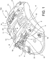
figure 1 shows an axonometric view of a detail of a disc brake caliper, in which there are fitted pads supported by suspension pins and influenced by leaf springs interposed between such pads; -
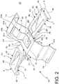
figure 2 shows an axonometric view, on enlarged scale, of a leaf spring infigure 1 ; -
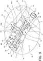
figure 3 shows an enlarged view of a portion of the disc brake caliper infigure 1 , including the leaf spring infigure 2 . - In the aforesaid
figures 1 to 3 , equal or similar elements and components are indicated with the same numerals. - With reference to
figures 1 and3 , 100 globally indicates a disc brake caliper, comprising acaliper body 10 positioned astride a disc of the disc brake (not shown). Such acaliper body 10 is fitted with a pair of half-bodies bodies central aperture 22 of thecaliper body 10. Furthermore, thecaliper body 10 comprises a first 13 and a second 14 connection bridge placed astride the disc of the disc brake at such acentral aperture 22. - The
caliper body 10 can be of the monoblock type, in which the half-bodies bodies - The
caliper body 10 is configured to delimit acompartment 15 for accommodatingbrake pads 2, 3 supported by saidcaliper body 10 by means of respective suspension pins forpads 4, 4', 5, 5'. In reference tofigures 1 ,3 , thecaliper body 10 comprises first suspension pins 4, 4' andsecond suspension pins 5, 5' of the pads. In particular, thepads 2, 3 are hung to thecaliper body 10 by means of the aforesaid pins by means of respective suspension slots (not shown) obtained in the plates of the pads. The half-bodies caliper body 10 are arranged on opposite sides with respect to thehousing compartment 15 in an axial direction X-X parallel to the rotation axis of the associable brake disc. - As known, the brake disc has two opposite friction surfaces (not shown in the drawings) against which the
opposite brake pads 2, 3 accommodated incompartment 15 of thecaliper body 10 abut during the braking action. - The plates of the
pads 2, 3 each include afirst side 42 facing the disc of the disc brake, connected to an oppositesecond side 44 by means of acorner 43 facing the above-mentionedcentral aperture 22. Such asecond side 44 ofpad 2, 3 faces aninner wall 90 of the half-bodies - One or more pistons acts on the
second side 44 of the plate during the braking step to press the oppositefirst side 42 against the braking band of the brake disc. In particular, a friction material (not shown) is connected on such afirst side 42 of the plate. Advantageously,caliper 100 comprises a first 50 and a second 51 leaf spring, for example cross-shaped, to influence thepads 2, 3 in said axial direction X-X. In particular, thefirst leaf spring 50 is adapted to act between thepads 2, 3 and between thefirst connection bridge 13 and thefirst end bridge 20 of the half-bodies second leaf spring 51 is adapted to act between thepads 2, 3 and between thesecond connection bridge 14 and thesecond end bridge 21 of the half-bodies - In greater detail, in reference to
figure 1 , thefirst leaf spring 50 is adapted to act on a first portion of thepads 2, 3 at the first suspension pins 4, 4', that is the portion of the pads with which the latter are suspended to the first pins 4, 4'. Thesecond leaf spring 51 is adapted to act on a second portion of thepads 2, 3 at thesecond suspension pins 5, 5', that is the portion of the pads with which the latter are suspended to thesecond pins 5, 5'. - The
aforesaid leaf springs - Below, in reference to
figures 2 and3 , there is described the first leaf spring orspring 50. Entirely similar considerations also hold true for thesecond leaf spring 51. - In accordance with an embodiment, such a
leaf spring 50 comprises aspring body 60 made by means of cross junction of a first beam or bow-shapedlongitudinal beam 61 and of a second beam or shapedcross beam 62. Such first andsecond beams spring 50, for example by means of a threaded connection means. In particular, the above-mentionedcross beam 62 of theleaf spring 50 is connected to thelongitudinal beam 61 at a central base portion 64 of the spring or central base. - Such a
longitudinal beam 61 comprises a first 61a and a second 61b half-beam. The first half-beam 61a comprises a shapedfirst end 73 of thelongitudinal beam 61 adapted to be removably constrained to thefirst connection bridge 13. In particular, such afirst end 73 comprises an L-shaped engagement portion, connected to aninclined surface 61c of the first half-beam 61a which projects from the central base 64 ofspring 50. The L-shapedengagement portion 73 is adapted to be inserted below thefirst connection bridge 13 at a chamfer 73' obtained in such a connection bridge. - The second half-
beam 61b of thelongitudinal beam 61 is substantially S-shaped and is fitted with a shapedsecond end 74 opposite to such afirst end 73 to removably constrain thelongitudinal beam 61 to thefirst end bridge 20. In particular, such a shaped second end materializes in aclaw 74 adapted to be inserted in a slot (not shown) obtained in thefirst end bridge 20. - The aforesaid longitudinal bow-
beam 61 constrained to thefirst connection bridge 13 and to thefirst end bridge 20 is adapted to arch in direction orthogonal to the axial direction X-X away from the disc to discharge on the latter the vertical stresses countering the movements of thepads 2, 3. - The body of
spring 60 further comprises aleaf element 63 constrained mechanically to the aforesaid first andsecond beams leaf element 63 comprises a second,curved end portion 63a opposite to the aforesaid first portion 63' in sliding contact on theinclined surface 61c of the first half-beam 61a, for damping the vibrations of the pads generated during the braking steps and therefore for reducing the noisiness of the brake. Additionally, such aleaf element 63 comprises an archedintermediate portion 63b between the first 63' and the second 63a end portion adapted to give elasticity to the element. In other words, theleaf element 63 is configured to increase the rigidity (that is to say, the elastic resistance) of the first half-beam 61a with respect to the rigidity of the second half-beam 61b. The reduced rigidity of the second half-beam 61b allows easier positioning and easier manual deformation ofspring 50. - The
cross beam 62 of the above-mentionedspring 50 in particular operates to influence thepads 2, 3 at suspension portions of thepads 2, 3 towards thepins 4, 4', 5, 5'. - Such a
cross beam 62 comprises a first 65 and a second 66 opposite branches influencing the pads projecting away from the central base 64 ofspring 50. - In accordance with an embodiment, the central base 64 of
spring 50 lies substantially on a base plane P. Such a base plane P also defines an axial axis X lying on plane P substantially coincident with the axial direction X-X parallel to the rotation axis of the brake disc. - The central base 64 comprises a first
base edge portion 69, a secondbase edge portion 70, a thirdbase edge portion 71 and a fourthbase edge portion 72. - Advantageously, the first 65 and the second 66 opposite branches influencing the pads are connected to the first
base edge portion 69 of the central base 64 and to the opposite thirdbase edge portion 71 of the central base 64, respectively. - The first half-
beam 61a and the second half-beam 61b of thelongitudinal beam 61 are connected to the secondbase edge portion 70 and to the opposite fourthbase edge portion 72 of the central base 64, respectively. - Each of the above-mentioned branches influencing the
pads branch branch side rectilinear corner - In accordance with an advantageous embodiment, each of the aforesaid branches influencing the
pads wing branch wing pads 2, 3. In particular, thewings spring 50 form an axial preload on the plates of thepads 2, 3. - In reference to
figure 2 , eachwing corner 43 of therespective pad 2, 3. - Advantageously, each
wing pads second side 44 ofpad 2, 3 by keeping it away from aninner wall 90 of the half-bodies - Furthermore, each
wing pads first side 42 ofpad 2, 3 away from the disc in the axial direction X-X and to influence such a pad in suspension on the first pins 4, 4' in a direction R orthogonal to the axial direction X-X away from thefirst connection bridge 13 and approaching the axis of the disc. - In accordance with a preferred embodiment, such first influencing means comprise a curved portion 8 of the wing shaped as a
hook spring 50. Such a curved portion 8 is adapted to form, withhook second side 44 of thepads 2, 3. - In accordance with a preferred embodiment, such second influencing means comprise a folded portion of
wing wing first edge 55 constrained towing free edge 56 projecting towards the disc of the disc brake. - In accordance with an embodiment of the invention, said folded portion of
wing - It is noted that the folded portion of
wing wing wing - In an embodiment, such a first plane P1, P2 on which
wing spring 50 lies is inclined with respect to plane P of the central base portion 64. - In reference to
figure 3 ,corner 43 of eachpad 2, 3 is interposed between the curved portion 8 shaped as ahook wing undeformed spring 50, such a folded portion ofwing first side 42 of thepads 2, 3 - in particular the portion of side close to corner 43 - away from the disc in the axial direction X-X. Furthermore, such a folded portion ofwing pads 2, 3 in suspension on the first pins 4, 4' in direction R orthogonal to the axial direction X-X away from thefirst connection bridge 13, that is, to hold the pads elastically in a "lowered" position. - In such a case, the folded portion of
wing hook pads 2, 3 in a predetermined position incompartment 15 of thecaliper body 10. Thereby, thesecond side 44 of thepads 2, 3 is kept constantly away from theinner wall 90 of the half-bodies - In braking step, such a moving away from influencing or thrust action exerted by the folded portion of
wing springs first side 42 of thepads 2, 3 is overcome by the braking action exerted by the pistons on the pads: thepads 2, 3 are pressed against the braking band of the brake disc; thesprings pads 2, 3. In particular, the folded portion ofwing free edge 56 of such a portion of wing approaches surface 7 ofwing corner 43, thus moving away from the disc. - In braking the release step, the folded portion of
wing springs pads 2, 3 away from the brake disc, thus avoiding contact between thepads 2, 3 and the brake disc. Furthermore, the curved portion 8 shaped as ahook pads 2, 3 in a predetermined position incompartment 15 of thecaliper body 10, thus preventing the same from excessively approaching theinner wall 90 of thecaliper body 10. - In other words, with the present invention, it is avoided that the
second side 44 of the plate ofpad 2, 3 can come in contact with theinner wall 90 of the half-bodies caliper 100. Obviously, in its practical construction, the above-described disc brake caliper fitted with springs may also take different shapes and designs than that shown above, without departing from the present scope of protection. - Furthermore, all details can be replaced by technically equivalent elements and any dimension, shape and material can be employed, as required.
Claims (9)
- Disc brake caliper (100) comprising:a caliper body (10) place astride the disc of a disc brake, fitted with a pair of half-bodies (11, 12) connected to each other by means of a first and a second end bridge (20, 21) suitable to delimit a central aperture (22) of the caliper body (10), and by means of a first (13) and a second (14) connection bridge placed astride the disc of the brake disc at said central aperture (22),said caliper body (10) housing brake pads (2, 3) supported by suspension pins for pads (4, 4', 5, 5') positioned in an axial direction (X-X) of the caliper body, said pads having a first side (42) facing the disc of the disc brake, connected to an opposite second side (44) by means of a corner (43) facing said central aperture (22),said caliper (100) further comprising a first (50) and a second (51) cross-shaped leaf spring to influence the pads (2,3) in said axial direction (X-X),wherein said first (50)/second (51) spring is suitable to act between the pads (2, 3) and between the first/second connection bridge (13, 14) and the first/second end bridge (20, 21) of the half-bodies (11, 12), said first (50)/second (51) leaf spring comprising a bow-shaped longitudinal beam (61) having a shaped first end (73) suitable to be removably constrained to the first/second connection bridge (13, 14) and an opposite second shaped end (74) suitable to be removably constrained to the first/second end bridge (20, 21),wherein each of said first (50) and second (51) leaf springs comprises:a cross beam (62) connected to the longitudinal beam (61) at a central base portion (64) of the spring, to influence the pads (2,3) at suspension portions of the pads (2, 3) towards the pins (4, 4', 5, 5'),said cross beam (62) including wings (81, 82) which project from the central base portion (64) of the spring in said axial direction (X-X),each of said wings (81, 82) having a surface (7) facing the disc of the disc brake suitable to rest on the corner (43) of the respective pad (2, 3),each of said wings (81, 82) comprising first means for influencing the pads (8, 83, 84) to influence the second side (44) of the pad (2, 3) keeping it away from an inner wall (90) of the half-bodies (11,12),each of said wings (81, 82) comprising second means for influencing the pads (85, 86, 55, 56) to influence the first side (42) of the pad (2,3) away from the disc in said axial direction (X-X) and to influence said pad in suspension on the pins (4, 4', 5, 5') in a direction (R) orthogonal to said axial direction (X-X) away from said first (13) and second (14) connection bridge.
- Disc brake caliper (100) according to claim 1, wherein:- said first means for influencing the pads comprise a curved portion (8) shaped as a hook (83,84) distal from the central base portion (64) of the leaf spring (50, 51);- said second means for influencing the pads comprise a folded portion of wing (85, 86) away from said surface (7) of the wing, said folded portion of the wing (85,86) having a first edge (55) constrained to the wing (81, 82) in the vicinity of said curved section (8) and an opposite second free edge (56) projecting towards the disc of the disc brake.
- Caliper (100) of the disc brake according to claim 2, wherein said folded portion of the wing (85, 86) projects towards the disc of the disc brake remaining substantially rectilinear.
- Caliper (100) of the disc brake according to claim 1, wherein said longitudinal beam (61) of the spring (50, 51) comprises a first (61a) half-beam comprising said first end (73) suitable to be removably constrained to first (13)/second (14) connection bridge of the caliper body (10), said first end (73) of the longitudinal beam comprising an L-shaped engagement portion, connected to an inclined surface (61c) of the first half-beam (61a) which projects from the central base (64) of the spring (50, 51).
- Caliper (100) of the disc brake according to claim 1, wherein said longitudinal beam (61) of the spring (50, 51) comprises a second (61b) half-beam comprising said second end (74) shaped to removably constrain the longitudinal beam (61) to the first (20)/second (21) end bridge of the caliper body (10), said second end of the longitudinal beam (61) comprising a claw (74) suitable to be inserted in a respective slot made in the first/second end bridge.
- Caliper (100) of the disc brake according to claim 4, wherein said spring (50, 51) further comprises a leaf element (63) having a respective first end portion (63') mechanically constrained to the central base portion (64) of the spring, said leaf element (63) comprising a second, curved end portion (63a) opposite said first end portion (63') in sliding contact on the inclined surface (61c) of the first half-beam (61a).
- Caliper (100) of the disc brake according to claim 6, wherein said leaf element (63) comprises an arched intermediate portion (63b) between said first (63 ') and second (63a) end portion, said leaf element being configured to increase the elastic resistance of the first half-beam (61a) of the longitudinal beam (61) compared to that of the second half-beam (61b).
- Caliper (100) of the disc brake according to claim 1, wherein said central base portion (64) of the spring (50, 51) lies substantially on a base plane (P) defining an axial axis (X) lying on the plane substantially coincident with the axial direction (X-X) parallel to the rotation axis of the disc,
said cross beam (62) of the spring (50, 51) including a first (65) and an opposite second (66) branch influencing the pads (2, 3) connected to a first base edge portion (69) of the central base portion (64) of the spring and an opposite second base edge portion (71) of said central base portion (64), respectively, each of said branches influencing the pads (65, 66) comprising a folded portion of the branch (75, 76) which positions itself transversely to the plane (P) on which the central base portion (64) lies and which is connected to the respective wing (81, 82). - Caliper (100) of the disc brake according to claim 8, wherein said wings (81, 82) of the spring lie on a first plane (P1, P2) inclined in relation to the plane (P) on which the central base portion (64) lies.
Applications Claiming Priority (2)
| Application Number | Priority Date | Filing Date | Title |
|---|---|---|---|
| ITBG20140031 | 2014-08-01 | ||
| PCT/IB2015/055775 WO2016016841A2 (en) | 2014-08-01 | 2015-07-30 | Disc brake caliper employing a spring to influence pads acting on the disc of the disc brake |
Publications (2)
| Publication Number | Publication Date |
|---|---|
| EP3175134A2 EP3175134A2 (en) | 2017-06-07 |
| EP3175134B1 true EP3175134B1 (en) | 2018-03-21 |
Family
ID=51628193
Family Applications (1)
| Application Number | Title | Priority Date | Filing Date |
|---|---|---|---|
| EP15753465.2A Not-in-force EP3175134B1 (en) | 2014-08-01 | 2015-07-30 | Disc brake caliper employing a spring to influence pads acting on the disc of the disc brake |
Country Status (4)
| Country | Link |
|---|---|
| US (1) | US9970495B2 (en) |
| EP (1) | EP3175134B1 (en) |
| CN (1) | CN106852165B (en) |
| WO (1) | WO2016016841A2 (en) |
Cited By (1)
| Publication number | Priority date | Publication date | Assignee | Title |
|---|---|---|---|---|
| US11773932B2 (en) | 2018-12-20 | 2023-10-03 | Brembo S.P.A. | Pad return spring for a disc brake caliper body |
Families Citing this family (17)
| Publication number | Priority date | Publication date | Assignee | Title |
|---|---|---|---|---|
| USD861559S1 (en) | 2016-06-30 | 2019-10-01 | Freni Brembo S.P.A. | Disc brake calliper |
| USD862327S1 (en) | 2016-06-30 | 2019-10-08 | Freni Brembo S.P.A. | Disc brake calliper |
| USD892007S1 (en) * | 2016-06-30 | 2020-08-04 | Freni Brembo S.P.A. | Disc brake calliper |
| CN107939868B (en) * | 2016-10-12 | 2020-07-10 | 光阳工业股份有限公司 | The caliper structure of the disc brake system |
| USD854985S1 (en) * | 2016-12-19 | 2019-07-30 | Freni Brembo S.P.A. | Disc brake caliper |
| TWD193554S (en) * | 2016-12-19 | 2018-10-21 | A P 賽車股份有限公司 | Disc brake calliper |
| TWD186793S (en) * | 2016-12-23 | 2017-11-21 | 捷加企業股份有限公司 | Part of the electronic brake caliper |
| USD861560S1 (en) * | 2017-08-14 | 2019-10-01 | Preferred Tool & Die, Inc. | Brake caliper hardware set |
| DE102017008195A1 (en) * | 2017-08-30 | 2019-02-28 | Lucas Automotive Gmbh | Brake pad restoring device for a disc brake of a vehicle brake system |
| IT201700097892A1 (en) * | 2017-08-31 | 2019-03-03 | Freni Brembo Spa | BRAKE DISC FOR DISC BRAKE |
| US20190120308A1 (en) * | 2017-10-19 | 2019-04-25 | Hb Performance Systems, Inc. | Anti-rattle spring for brake caliper assembly |
| DE102018002886A1 (en) * | 2018-04-10 | 2019-10-10 | Lucas Automotive Gmbh | Brake pad arrangement for a disc brake of a vehicle brake system |
| IT201800006498A1 (en) * | 2018-06-20 | 2019-12-20 | SPRING FOR FRICTION PADS IN A DISC BRAKE CALIPER | |
| USD931171S1 (en) * | 2019-03-27 | 2021-09-21 | Freni Brembo S.P.A. | Brake caliper |
| USD928674S1 (en) | 2020-01-08 | 2021-08-24 | Preferred Tool & Die, Inc. | Brake caliper hardware |
| JP7456885B2 (en) * | 2020-08-07 | 2024-03-27 | 曙ブレーキ工業株式会社 | disc brake device |
| IT202100000749A1 (en) * | 2021-01-18 | 2022-07-18 | Brembo Spa | RIBBON SPRING AND SPRING RIBBON AND BRAKE PAD ASSEMBLY |
Family Cites Families (23)
| Publication number | Priority date | Publication date | Assignee | Title |
|---|---|---|---|---|
| GB1223989A (en) * | 1968-07-11 | 1971-03-03 | Teves Gmbh Alfred | Floating caliper disc brake |
| US3783980A (en) * | 1971-10-13 | 1974-01-08 | Itt | Brake lining holding arrangement for spot-type disc brakes |
| DE2301595C3 (en) * | 1973-01-13 | 1975-09-11 | Daimler-Benz Ag, 7000 Stuttgart | Brake shoe holding and supporting device for the brake shoes of a partially lined disc brake, in particular for motor vehicles |
| FR2425579A1 (en) * | 1978-05-11 | 1979-12-07 | Dba | DISC BRAKE AND NOISE SPRING FOR SUCH A BRAKE |
| JPS624744Y2 (en) * | 1980-06-23 | 1987-02-03 | ||
| FR2508128A1 (en) * | 1981-06-22 | 1982-12-24 | Tokico Ltd | DISC BRAKE |
| DE3124631A1 (en) * | 1981-06-23 | 1983-01-13 | Tokico Ltd., Kawasaki, Kanagawa | Brake lining spring for a spot-type disc brake |
| EP0794349B1 (en) * | 1996-03-06 | 2001-06-13 | Aisin Seiki Kabushiki Kaisha | Disc brake caliper assembly |
| JPH09329164A (en) * | 1996-04-08 | 1997-12-22 | Aisin Seiki Co Ltd | Disc brake |
| DE19626303A1 (en) * | 1996-07-01 | 1998-01-08 | Teves Gmbh Alfred | Retaining spring for a housing of a partial brake disc brake |
| SE523552C2 (en) * | 2000-05-31 | 2004-04-27 | Haldex Brake Prod Ab | Brake mechanism and a method for controlling the power gain |
| KR100428144B1 (en) * | 2001-09-06 | 2004-04-30 | 현대자동차주식회사 | An automotive brake caliper for decreasing noise |
| JP4477540B2 (en) * | 2005-04-28 | 2010-06-09 | 日立オートモティブシステムズ株式会社 | Disc brake |
| JP4732256B2 (en) * | 2006-06-26 | 2011-07-27 | 曙ブレーキ工業株式会社 | Disc brake pad clip |
| CN200961650Y (en) * | 2006-11-06 | 2007-10-17 | 武汉元丰汽车零部件有限公司 | Integral caliper type floating caliper type pneumatic brake |
| DE102008020346A1 (en) * | 2008-04-23 | 2009-10-29 | Lucas Automotive Gmbh | Disk brake for motor vehicle brake system, has lining retaining spring fixed to housing cross beam with contact surface and positionably engaged to beam with retaining plates that are angled against contact surface |
| DE102008022200B4 (en) * | 2008-05-06 | 2025-03-13 | Zf Active Safety Gmbh | Brake pad arrangement for disc brakes |
| ITMI20111693A1 (en) * | 2011-09-20 | 2013-03-21 | Freni Brembo Spa | BRAKE CALIPER FOR DISC BRAKE |
| JP2013204742A (en) * | 2012-03-29 | 2013-10-07 | Honda Motor Co Ltd | Disk brake device |
| ITPD20120398A1 (en) * | 2012-12-20 | 2014-06-21 | Freni Brembo Spa | BRAKE CALIPER WITH DISC |
| WO2015155708A1 (en) * | 2014-04-08 | 2015-10-15 | Freni Brembo S.P.A. | Disc brake pad, spring for disc brake caliper and disk brake caliper assembly |
| US10718393B2 (en) * | 2014-05-27 | 2020-07-21 | Freni Brembo S.P.A. | Spring of a caliper of a disc brake |
| EP3023666B2 (en) * | 2014-11-20 | 2022-09-14 | Meritor Heavy Vehicle Braking Systems (UK) Limited | Disc brake assembly |
-
2015
- 2015-07-30 CN CN201580053601.1A patent/CN106852165B/en active Active
- 2015-07-30 US US15/500,840 patent/US9970495B2/en active Active
- 2015-07-30 WO PCT/IB2015/055775 patent/WO2016016841A2/en not_active Ceased
- 2015-07-30 EP EP15753465.2A patent/EP3175134B1/en not_active Not-in-force
Cited By (1)
| Publication number | Priority date | Publication date | Assignee | Title |
|---|---|---|---|---|
| US11773932B2 (en) | 2018-12-20 | 2023-10-03 | Brembo S.P.A. | Pad return spring for a disc brake caliper body |
Also Published As
| Publication number | Publication date |
|---|---|
| CN106852165B (en) | 2019-04-23 |
| CN106852165A (en) | 2017-06-13 |
| WO2016016841A2 (en) | 2016-02-04 |
| US9970495B2 (en) | 2018-05-15 |
| EP3175134A2 (en) | 2017-06-07 |
| WO2016016841A3 (en) | 2016-04-07 |
| US20170219034A1 (en) | 2017-08-03 |
Similar Documents
| Publication | Publication Date | Title |
|---|---|---|
| US9970495B2 (en) | Disc brake caliper employing a spring to influence pads acting on the disc of the disc brake | |
| JP6085717B2 (en) | Disc brakes with stable brake pads and related methods for assembling and replacing pads | |
| EP1649185B1 (en) | Spring member for disc-brake calipers and disc-brake caliper | |
| EP3810950B1 (en) | Spring for friction pads in a disc brake caliper | |
| CN108779820B (en) | Disc brake, in particular for a commercial vehicle | |
| CN107429766B (en) | Pad and spring assembly for disc brake caliper | |
| US20160160945A1 (en) | Pad Retaining Spring for a Brake Pad and Brake Pad Retainer for a Disc Brake on a Motor Vehicle | |
| CN118128847A (en) | Friction lining assembly for a partially lined motor vehicle disc brake of the sliding caliper type | |
| JP2018508722A (en) | Disc brake having at least one spring for elastic return of brake pad, elastic return spring, and replacement kit | |
| BR112014014269B1 (en) | guiding element of a disc brake and disc brake pad | |
| US7810617B2 (en) | Friction element and disc brake | |
| EP3452736B1 (en) | Hydraulic disc brake assembly and pad assembly for same | |
| US10240649B2 (en) | Caliper for disc brake | |
| EP3680504B1 (en) | Vehicular disc brake | |
| JP2019120291A (en) | Pad clip, assembly of pad clip and returning spring and floating type disc brake | |
| US3768605A (en) | Disc brake with anti-vibration anchoring arrangement | |
| US9341220B2 (en) | Brake pad retention device and method | |
| WO2021215436A1 (en) | Floating caliper | |
| JP7658138B2 (en) | Floating Caliper | |
| US20160169306A1 (en) | Reinforced Disc Brake Pad Backing Plate And Reinforced Brake Pad | |
| JP2014070652A (en) | Disc brake, and pad support | |
| JP2023110714A (en) | floating caliper | |
| BR112023021700A2 (en) | VEHICLE DISC BRAKE, AND, FRICTION PADS USED FOR A VEHICLE DISC BRAKE | |
| JP2018017350A (en) | Disc brake device |
Legal Events
| Date | Code | Title | Description |
|---|---|---|---|
| 17P | Request for examination filed |
Effective date: 20170130 |
|
| AK | Designated contracting states |
Kind code of ref document: A2 Designated state(s): AL AT BE BG CH CY CZ DE DK EE ES FI FR GB GR HR HU IE IS IT LI LT LU LV MC MK MT NL NO PL PT RO RS SE SI SK SM TR |
|
| AX | Request for extension of the european patent |
Extension state: BA ME |
|
| PUAI | Public reference made under article 153(3) epc to a published international application that has entered the european phase |
Free format text: ORIGINAL CODE: 0009012 |
|
| DAV | Request for validation of the european patent (deleted) | ||
| DAX | Request for extension of the european patent (deleted) | ||
| GRAP | Despatch of communication of intention to grant a patent |
Free format text: ORIGINAL CODE: EPIDOSNIGR1 |
|
| INTG | Intention to grant announced |
Effective date: 20171212 |
|
| GRAS | Grant fee paid |
Free format text: ORIGINAL CODE: EPIDOSNIGR3 |
|
| GRAA | (expected) grant |
Free format text: ORIGINAL CODE: 0009210 |
|
| AK | Designated contracting states |
Kind code of ref document: B1 Designated state(s): AL AT BE BG CH CY CZ DE DK EE ES FI FR GB GR HR HU IE IS IT LI LT LU LV MC MK MT NL NO PL PT RO RS SE SI SK SM TR |
|
| REG | Reference to a national code |
Ref country code: GB Ref legal event code: FG4D |
|
| REG | Reference to a national code |
Ref country code: CH Ref legal event code: EP |
|
| REG | Reference to a national code |
Ref country code: AT Ref legal event code: REF Ref document number: 981446 Country of ref document: AT Kind code of ref document: T Effective date: 20180415 |
|
| REG | Reference to a national code |
Ref country code: IE Ref legal event code: FG4D |
|
| REG | Reference to a national code |
Ref country code: DE Ref legal event code: R096 Ref document number: 602015009181 Country of ref document: DE |
|
| REG | Reference to a national code |
Ref country code: NL Ref legal event code: MP Effective date: 20180321 |
|
| PG25 | Lapsed in a contracting state [announced via postgrant information from national office to epo] |
Ref country code: FI Free format text: LAPSE BECAUSE OF FAILURE TO SUBMIT A TRANSLATION OF THE DESCRIPTION OR TO PAY THE FEE WITHIN THE PRESCRIBED TIME-LIMIT Effective date: 20180321 Ref country code: NO Free format text: LAPSE BECAUSE OF FAILURE TO SUBMIT A TRANSLATION OF THE DESCRIPTION OR TO PAY THE FEE WITHIN THE PRESCRIBED TIME-LIMIT Effective date: 20180621 Ref country code: CY Free format text: LAPSE BECAUSE OF FAILURE TO SUBMIT A TRANSLATION OF THE DESCRIPTION OR TO PAY THE FEE WITHIN THE PRESCRIBED TIME-LIMIT Effective date: 20180321 Ref country code: HR Free format text: LAPSE BECAUSE OF FAILURE TO SUBMIT A TRANSLATION OF THE DESCRIPTION OR TO PAY THE FEE WITHIN THE PRESCRIBED TIME-LIMIT Effective date: 20180321 Ref country code: LT Free format text: LAPSE BECAUSE OF FAILURE TO SUBMIT A TRANSLATION OF THE DESCRIPTION OR TO PAY THE FEE WITHIN THE PRESCRIBED TIME-LIMIT Effective date: 20180321 |
|
| REG | Reference to a national code |
Ref country code: LT Ref legal event code: MG4D |
|
| REG | Reference to a national code |
Ref country code: AT Ref legal event code: MK05 Ref document number: 981446 Country of ref document: AT Kind code of ref document: T Effective date: 20180321 |
|
| PG25 | Lapsed in a contracting state [announced via postgrant information from national office to epo] |
Ref country code: GR Free format text: LAPSE BECAUSE OF FAILURE TO SUBMIT A TRANSLATION OF THE DESCRIPTION OR TO PAY THE FEE WITHIN THE PRESCRIBED TIME-LIMIT Effective date: 20180622 Ref country code: RS Free format text: LAPSE BECAUSE OF FAILURE TO SUBMIT A TRANSLATION OF THE DESCRIPTION OR TO PAY THE FEE WITHIN THE PRESCRIBED TIME-LIMIT Effective date: 20180321 Ref country code: BG Free format text: LAPSE BECAUSE OF FAILURE TO SUBMIT A TRANSLATION OF THE DESCRIPTION OR TO PAY THE FEE WITHIN THE PRESCRIBED TIME-LIMIT Effective date: 20180621 Ref country code: SE Free format text: LAPSE BECAUSE OF FAILURE TO SUBMIT A TRANSLATION OF THE DESCRIPTION OR TO PAY THE FEE WITHIN THE PRESCRIBED TIME-LIMIT Effective date: 20180321 Ref country code: LV Free format text: LAPSE BECAUSE OF FAILURE TO SUBMIT A TRANSLATION OF THE DESCRIPTION OR TO PAY THE FEE WITHIN THE PRESCRIBED TIME-LIMIT Effective date: 20180321 |
|
| PG25 | Lapsed in a contracting state [announced via postgrant information from national office to epo] |
Ref country code: NL Free format text: LAPSE BECAUSE OF FAILURE TO SUBMIT A TRANSLATION OF THE DESCRIPTION OR TO PAY THE FEE WITHIN THE PRESCRIBED TIME-LIMIT Effective date: 20180321 Ref country code: PL Free format text: LAPSE BECAUSE OF FAILURE TO SUBMIT A TRANSLATION OF THE DESCRIPTION OR TO PAY THE FEE WITHIN THE PRESCRIBED TIME-LIMIT Effective date: 20180321 Ref country code: EE Free format text: LAPSE BECAUSE OF FAILURE TO SUBMIT A TRANSLATION OF THE DESCRIPTION OR TO PAY THE FEE WITHIN THE PRESCRIBED TIME-LIMIT Effective date: 20180321 Ref country code: RO Free format text: LAPSE BECAUSE OF FAILURE TO SUBMIT A TRANSLATION OF THE DESCRIPTION OR TO PAY THE FEE WITHIN THE PRESCRIBED TIME-LIMIT Effective date: 20180321 Ref country code: IT Free format text: LAPSE BECAUSE OF FAILURE TO SUBMIT A TRANSLATION OF THE DESCRIPTION OR TO PAY THE FEE WITHIN THE PRESCRIBED TIME-LIMIT Effective date: 20180321 Ref country code: AL Free format text: LAPSE BECAUSE OF FAILURE TO SUBMIT A TRANSLATION OF THE DESCRIPTION OR TO PAY THE FEE WITHIN THE PRESCRIBED TIME-LIMIT Effective date: 20180321 |
|
| PG25 | Lapsed in a contracting state [announced via postgrant information from national office to epo] |
Ref country code: SK Free format text: LAPSE BECAUSE OF FAILURE TO SUBMIT A TRANSLATION OF THE DESCRIPTION OR TO PAY THE FEE WITHIN THE PRESCRIBED TIME-LIMIT Effective date: 20180321 Ref country code: SM Free format text: LAPSE BECAUSE OF FAILURE TO SUBMIT A TRANSLATION OF THE DESCRIPTION OR TO PAY THE FEE WITHIN THE PRESCRIBED TIME-LIMIT Effective date: 20180321 Ref country code: AT Free format text: LAPSE BECAUSE OF FAILURE TO SUBMIT A TRANSLATION OF THE DESCRIPTION OR TO PAY THE FEE WITHIN THE PRESCRIBED TIME-LIMIT Effective date: 20180321 Ref country code: CZ Free format text: LAPSE BECAUSE OF FAILURE TO SUBMIT A TRANSLATION OF THE DESCRIPTION OR TO PAY THE FEE WITHIN THE PRESCRIBED TIME-LIMIT Effective date: 20180321 |
|
| PG25 | Lapsed in a contracting state [announced via postgrant information from national office to epo] |
Ref country code: PT Free format text: LAPSE BECAUSE OF FAILURE TO SUBMIT A TRANSLATION OF THE DESCRIPTION OR TO PAY THE FEE WITHIN THE PRESCRIBED TIME-LIMIT Effective date: 20180723 |
|
| REG | Reference to a national code |
Ref country code: DE Ref legal event code: R097 Ref document number: 602015009181 Country of ref document: DE |
|
| PLBE | No opposition filed within time limit |
Free format text: ORIGINAL CODE: 0009261 |
|
| STAA | Information on the status of an ep patent application or granted ep patent |
Free format text: STATUS: NO OPPOSITION FILED WITHIN TIME LIMIT |
|
| PG25 | Lapsed in a contracting state [announced via postgrant information from national office to epo] |
Ref country code: DK Free format text: LAPSE BECAUSE OF FAILURE TO SUBMIT A TRANSLATION OF THE DESCRIPTION OR TO PAY THE FEE WITHIN THE PRESCRIBED TIME-LIMIT Effective date: 20180321 |
|
| 26N | No opposition filed |
Effective date: 20190102 |
|
| REG | Reference to a national code |
Ref country code: CH Ref legal event code: PL |
|
| PG25 | Lapsed in a contracting state [announced via postgrant information from national office to epo] |
Ref country code: MC Free format text: LAPSE BECAUSE OF FAILURE TO SUBMIT A TRANSLATION OF THE DESCRIPTION OR TO PAY THE FEE WITHIN THE PRESCRIBED TIME-LIMIT Effective date: 20180321 Ref country code: LU Free format text: LAPSE BECAUSE OF NON-PAYMENT OF DUE FEES Effective date: 20180730 |
|
| REG | Reference to a national code |
Ref country code: BE Ref legal event code: MM Effective date: 20180731 |
|
| PG25 | Lapsed in a contracting state [announced via postgrant information from national office to epo] |
Ref country code: FR Free format text: LAPSE BECAUSE OF NON-PAYMENT OF DUE FEES Effective date: 20180731 Ref country code: CH Free format text: LAPSE BECAUSE OF NON-PAYMENT OF DUE FEES Effective date: 20180731 Ref country code: LI Free format text: LAPSE BECAUSE OF NON-PAYMENT OF DUE FEES Effective date: 20180731 |
|
| REG | Reference to a national code |
Ref country code: IE Ref legal event code: MM4A |
|
| PG25 | Lapsed in a contracting state [announced via postgrant information from national office to epo] |
Ref country code: BE Free format text: LAPSE BECAUSE OF NON-PAYMENT OF DUE FEES Effective date: 20180731 Ref country code: SI Free format text: LAPSE BECAUSE OF FAILURE TO SUBMIT A TRANSLATION OF THE DESCRIPTION OR TO PAY THE FEE WITHIN THE PRESCRIBED TIME-LIMIT Effective date: 20180321 |
|
| PG25 | Lapsed in a contracting state [announced via postgrant information from national office to epo] |
Ref country code: IE Free format text: LAPSE BECAUSE OF NON-PAYMENT OF DUE FEES Effective date: 20180730 Ref country code: ES Free format text: LAPSE BECAUSE OF FAILURE TO SUBMIT A TRANSLATION OF THE DESCRIPTION OR TO PAY THE FEE WITHIN THE PRESCRIBED TIME-LIMIT Effective date: 20180321 |
|
| PG25 | Lapsed in a contracting state [announced via postgrant information from national office to epo] |
Ref country code: MT Free format text: LAPSE BECAUSE OF NON-PAYMENT OF DUE FEES Effective date: 20180730 |
|
| GBPC | Gb: european patent ceased through non-payment of renewal fee |
Effective date: 20190730 |
|
| PG25 | Lapsed in a contracting state [announced via postgrant information from national office to epo] |
Ref country code: TR Free format text: LAPSE BECAUSE OF FAILURE TO SUBMIT A TRANSLATION OF THE DESCRIPTION OR TO PAY THE FEE WITHIN THE PRESCRIBED TIME-LIMIT Effective date: 20180321 |
|
| PG25 | Lapsed in a contracting state [announced via postgrant information from national office to epo] |
Ref country code: GB Free format text: LAPSE BECAUSE OF NON-PAYMENT OF DUE FEES Effective date: 20190730 |
|
| PG25 | Lapsed in a contracting state [announced via postgrant information from national office to epo] |
Ref country code: HU Free format text: LAPSE BECAUSE OF FAILURE TO SUBMIT A TRANSLATION OF THE DESCRIPTION OR TO PAY THE FEE WITHIN THE PRESCRIBED TIME-LIMIT; INVALID AB INITIO Effective date: 20150730 Ref country code: MK Free format text: LAPSE BECAUSE OF NON-PAYMENT OF DUE FEES Effective date: 20180321 |
|
| PG25 | Lapsed in a contracting state [announced via postgrant information from national office to epo] |
Ref country code: IS Free format text: LAPSE BECAUSE OF FAILURE TO SUBMIT A TRANSLATION OF THE DESCRIPTION OR TO PAY THE FEE WITHIN THE PRESCRIBED TIME-LIMIT Effective date: 20180721 |
|
| REG | Reference to a national code |
Ref country code: DE Ref legal event code: R081 Ref document number: 602015009181 Country of ref document: DE Owner name: BREMBO S.P.A., CURNO, IT Free format text: FORMER OWNER: FRENI BREMBO S.P.A., CURNO, BERGAMO, IT |
|
| P01 | Opt-out of the competence of the unified patent court (upc) registered |
Effective date: 20230526 |
|
| PGFP | Annual fee paid to national office [announced via postgrant information from national office to epo] |
Ref country code: DE Payment date: 20240719 Year of fee payment: 10 |
|
| REG | Reference to a national code |
Ref country code: DE Ref legal event code: R119 Ref document number: 602015009181 Country of ref document: DE |
|
| PG25 | Lapsed in a contracting state [announced via postgrant information from national office to epo] |
Ref country code: DE Free format text: LAPSE BECAUSE OF NON-PAYMENT OF DUE FEES Effective date: 20260203 |