EP3174573B1 - Vacuum-assisted plasma separation - Google Patents
Vacuum-assisted plasma separation Download PDFInfo
- Publication number
- EP3174573B1 EP3174573B1 EP15826556.1A EP15826556A EP3174573B1 EP 3174573 B1 EP3174573 B1 EP 3174573B1 EP 15826556 A EP15826556 A EP 15826556A EP 3174573 B1 EP3174573 B1 EP 3174573B1
- Authority
- EP
- European Patent Office
- Prior art keywords
- plasma
- filter
- blood
- channel
- recess
- Prior art date
- Legal status (The legal status is an assumption and is not a legal conclusion. Google has not performed a legal analysis and makes no representation as to the accuracy of the status listed.)
- Active
Links
Images




Classifications
-
- G—PHYSICS
- G01—MEASURING; TESTING
- G01N—INVESTIGATING OR ANALYSING MATERIALS BY DETERMINING THEIR CHEMICAL OR PHYSICAL PROPERTIES
- G01N33/00—Investigating or analysing materials by specific methods not covered by groups G01N1/00 - G01N31/00
- G01N33/48—Biological material, e.g. blood, urine; Haemocytometers
- G01N33/483—Physical analysis of biological material
- G01N33/487—Physical analysis of biological material of liquid biological material
- G01N33/49—Blood
- G01N33/491—Blood by separating the blood components
-
- A—HUMAN NECESSITIES
- A61—MEDICAL OR VETERINARY SCIENCE; HYGIENE
- A61B—DIAGNOSIS; SURGERY; IDENTIFICATION
- A61B5/00—Measuring for diagnostic purposes; Identification of persons
- A61B5/15—Devices for taking samples of blood
- A61B5/150007—Details
- A61B5/150015—Source of blood
- A61B5/150022—Source of blood for capillary blood or interstitial fluid
-
- A—HUMAN NECESSITIES
- A61—MEDICAL OR VETERINARY SCIENCE; HYGIENE
- A61M—DEVICES FOR INTRODUCING MEDIA INTO, OR ONTO, THE BODY; DEVICES FOR TRANSDUCING BODY MEDIA OR FOR TAKING MEDIA FROM THE BODY; DEVICES FOR PRODUCING OR ENDING SLEEP OR STUPOR
- A61M1/00—Suction or pumping devices for medical purposes; Devices for carrying-off, for treatment of, or for carrying-over, body-liquids; Drainage systems
- A61M1/34—Filtering material out of the blood by passing it through a membrane, i.e. hemofiltration or diafiltration
-
- B—PERFORMING OPERATIONS; TRANSPORTING
- B01—PHYSICAL OR CHEMICAL PROCESSES OR APPARATUS IN GENERAL
- B01L—CHEMICAL OR PHYSICAL LABORATORY APPARATUS FOR GENERAL USE
- B01L3/00—Containers or dishes for laboratory use, e.g. laboratory glassware; Droppers
- B01L3/50—Containers for the purpose of retaining a material to be analysed, e.g. test tubes
- B01L3/502—Containers for the purpose of retaining a material to be analysed, e.g. test tubes with fluid transport, e.g. in multi-compartment structures
Definitions
- Plasma rather than whole blood, is generally the preferred sample for many clinical diagnostic tests.
- plasma is separated from whole blood as hemoglobin and other hemolysis products may interfere with detection of viral RNA.
- hemoglobin and other hemolysis products may interfere with assay results, plasma may need to be non-hemolyzed.
- US 2012/0145619 A1 provides a method of collecting a plasma fraction, wherein the channel assembly includes a channel housing which is rotatably interconnected with a rotatable centrifuge rotor assembly.
- WO 2014/024066 A1 pertains to a system and method for separating plasma and/or serum from blood for bilirubin level estimation.
- Other separation methods including laminar-flow filtration or capillary-action based processes, however, are also expensive, complex, slow, require large volumes of blood, or may lead to unacceptable levels of hemolysis.
- a capillary device is disclosed for analyzing blood using minimal sample volumes, e.g., fingerstick application.
- the plasma separation membrane to separate plasma from a blood sample is provided in US 2012/0220047 .
- any reference to "one embodiment,” “an embodiment,” “some embodiments,” “one example,” “for example,” or “an example” means that a particular element, feature, structure or characteristic described in connection with the embodiment is included in at least one embodiment.
- the appearance of the phrase “in some embodiments” or “one example” in various places in the specification is not necessarily all referring to the same embodiment, for example.
- the plasma separation system 10 may provide separation of plasma from blood using a vacuum force, and without using centrifugation or laminar-flow filtration based filtration processes.
- the separation of plasma from blood may be with minimal hemolysis and within a relatively short amount of time (e.g., 10-90 seconds) as compared to processes used currently within the industry.
- the plasma may be further used in one or more point-of-care assays.
- the plasma separation system 10 includes a housing 12 supporting or encompassing a blood separation well 14 connected via a first channel 16 to a plasma collection vessel 18.
- the housing 12 supports or encompasses a second channel 22 connecting the plasma collection vessel 18 to an outlet port 24 downstream of the plasma collection vessel 18.
- the plasma separation system 10 may also include a negative pressure source 26 that can be attached to the outlet port 24.
- the outlet port 24 can be configured to allow for the negative pressure source 26 to be attached thereto assist in enabling the operation of the plasma separation system 10.
- Negative pressure e.g., vacuum pressure
- the negative pressure source 26 is applied by the negative pressure source 26 to the outlet port 24, which also causes a vacuum to form in the blood separation well 14.
- plasma is separated from the blood.
- the magnitude of the negative pressure may be controlled to prevent hemolysis and/or leakage of cellular material.
- the separated plasma is collected in the plasma collection vessel 18.
- the plasma separation system 10 may be a single-use system.
- one or more components of the plasma separation system 10 may be disposable such that the plasma separation system 10 may be a multi-use system.
- one or more channels 16 and 22 may be lined such that the plasma collection vessel 18 and components of the blood separation well 14 may be removed, disposed of, and replaced for use with a second blood sample.
- the housing 12 may be formed of materials including, but not limited to, glass, plastic, and/or the like.
- the shape and size of the housing 12 may be dependent on shape and/or size of the blood separation well 14, channels 16 and 22, and/or the plasma collection vessel18.
- the housing 12 that is shown in Fig. 1 is a unitary integral device that is shaped to form the blood separation well 14, channels 16 and 22 and the plasma collection vessel 18. It should be understood that the housing 12 can be constructed of separate components which are connected together so that the blood separation well 14, channels 16 and 22 and the plasma collection vessel 18 communicate with each other.
- the size of the housing 12 may be minimized and determinate on an amount of plasma that is desired (e.g., 10-20 ⁇ L) to be extracted from a blood sample.
- the housing 12 may include a surface 28.
- the blood separation well 14 is positioned to intersect the surface 28 of the housing 12 such that the surface 28 at least partially surrounds the blood separation well 14.
- the blood separation well 14 includes a recess 30 intersecting the surface 28 of the housing 12 as illustrated in FIGS. 1 and 2 and in this instance the surface 28 may form a rim surrounding the recess 30.
- the recess 30 may include a proximal end 32 and a distal end 34 with a wall 36 spanning the length of the proximal end 32 to the distal end 34.
- the proximal end 32 may include a capillary surface 38 in which microchannels are formed in the proximal end 32 as discussed in more detail below with respect to FIG. 3 .
- the plasma separation device 10 is also provided with a filter 40, a separation membrane 42, and an adhesive member 44.
- the filter 40, the separation membrane 42 and the adhesive member 44 are stacked on the capillary surface 38 and disposed within the recess 30 such that the filter 40 is below the surface 28 of the housing 12 and fully disposed within the recess 30.
- the adhesive member 44 may be positioned on the capillary surface 38 with the separation membrane 42 and the filter 40 positioned thereon, respectively.
- the filter 40 and separation membrane 42 are pressure fit (also known as a "press fit") within the recess 30.
- the size and shape of the recess 30 may be dependent on the size and shape of the filter 40, the separation membrane 42, and/or the adhesive member 44.
- the size and shape of the recess 30 may be circular as the filter 40, separation membrane 42, and adhesive member 44 are circular.
- the shape may be any shape including, but not limited to, rectangular, triangular, or any fanciful shape.
- the volume of the recess 30, including the height and/or length of wall 36 may be dependent on thicknesses and/or the widths of one or more of the filter 40, separation membrane 42, and adhesive member 44.
- the filter 40, separation membrane 42 and the adhesive member 44 may be positioned within the recess 30 such that each remains between the proximal end 32 and the distal end 34 of the recess 30.
- the wall 36 is depicted as a straight wall, it should be understood that in some embodiments, the wall 36 can be stepped.
- one or more additional layers may be positioned on a first side 48 of the filter 40 to hold the filter 40 and separation membrane 42 within the blood separation well 14.
- a plastic O-ring may be positioned on the first surface 48 of the filter 40 to hold the filter 40 and separation membrane 42 within the blood separation well 14.
- a cap e.g., plastic formed cap
- the cap may be vented to allow for escape of gas to the outside environment. The cap may serve to hold the filter 40 in close proximity to the separation membrane 42.
- the filter 40 may expand in size such that the cap retains the filter 40 within the blood separation well 14. To that end, the filter 40 may expand in the direction of the separation membrane 42 positioning the filter 40 in close proximity or even in contact with the separation membrane 42.
- the filter 40 is formed of one or more layers 46. Each layer 46 may include the first side 48 and a second side 50 generally opposite of the first side 48. Generally, blood is provided onto and contacts the first side 48 of the filter 40 and passes through the layer 46 of the filter 40 such that filtered blood emerges on the second side 50.
- the filtered blood may include plasma and a portion of red blood cells that managed to pass through the layer 46. Some of the red blood cells will be captured within the layer 46 of the filter 40.
- the filter 40 generally removes a portion of the red blood cells from the blood and also may reduce separation burden of the separation membrane 42.
- the filter 40 may remove red blood cells (e.g., up to 70% of red blood cells) within the blood sample. The removal of a significant portion of red blood cells may aid the flow of the filtered blood through the separation membrane 42 and also reduce clogging of the separation membrane 42.
- Each layer 46 may be formed of materials including, but not limited to, glass fibers, polyester fibers, cellulose fibers, and/or the like.
- one or more filters 40 may be a commercially available filter under the trade name designations of VF1, VF2 and GFB, manufactured and distributed by Whatman, having a location in Maidstone Kent.
- one or more filters 40 may be a 9.5 mm disc of Whatman VF2 glass fiber.
- the second side 50 of the filter 40 is in proximity to or contact the separation membrane 42.
- the separation membrane 42 may remove the remaining red blood cells from the filtered blood providing filtered plasma.
- the filtered plasma may be essentially cell-free in that the filtered plasma includes minimal cellular debris.
- hemoglobin content with the filtered plasma may be comparable to plasma obtained by centrifuge techniques currently known within the industry.
- the plasma separation system 10 may solely comprise the separation membrane 42 without the use of the filter 40.
- the blood may be filtered solely through the separation membrane 42 providing filtered plasma using the methods as described herein.
- the separation membrane 42 may be formed of one or more layers 52. Each layer 52 may have a first side 54 and a second side 56. Generally, the filtered blood contacts the first side 54 of the separation membrane 42 passing through the layer 52 of the separation membrane such that filtered plasma emerges on the second side 56.
- the separation membrane 42 may be formed of materials including, but not limited to, nylon, polysulfone, polycarbonate and/or the like.
- the separation membrane 42 may be an ion-tracked etched membrane.
- the separation membrane 42 may be an asymmetric membrane.
- the separation membrane 42 may be formed having at least a first set of pores and a second set of pores, with the first set of pores and the second set of pores being different sizes.
- larger pores may be formed on the first side 54 of the separation membrane 42 and smaller pores may be formed on the second side 56 of the separation membrane 42 such that the filtered blood flows through the larger pores to the small pores. This may reduce blockage of red blood cells within the separation membrane 42.
- one or both of the filter 40 and/or separation membrane 42 may be treated with one or more blocking agents and/or surfactants. Treatment with blocking agents and/or surfactant may enhance analyte recovery and/or plasma separation efficiency.
- Surfactants may include, but are not limited to, Tween-20, and/or the like.
- the filter 40 and/or separation membrane 42 may be made more or less hydrophilic, more or less hydrophobic, more or less susceptible to protein adsorption, more or less positively charged, more or less negatively charged and/or the like.
- the filter 40 and/or separation membrane 42 may be treated with PAMAM dendrimers, Merquat, or other polycations.
- Blocking agents may include, but are not limited to bovine serum albumin, Seablock, gelatin, and/or the like.
- the second surface 56 of the separation membrane 42 may contact the adhesive member 44.
- the adhesive member 44 may prevent leakage of blood cells around the perimeter of the separation membrane 42.
- the adhesive member 44 may include a first surface 58 and a second surface 60 with the first surface 58 contacting the second surface 56 of the separation membrane 42 and the second surface 60 adhered to at least a portion of the capillary surface 38 of the recess 30. Generally, the adhesive member 44 aids in holding the separation membrane 42 within the recess 30.
- each surface 58 and 60 of the adhesive member 44 may include an adhesive material.
- Adhesive material may include, but is not limited to, polyethylene terephthalate (PET) with silicone adhesive, and/or the like.
- PET polyethylene terephthalate
- the adhesive member 44 may be a double-sided PET adhesive O-ring as illustrated in FIGS. 2A and 2D .
- the adhesive member 44 may be integral to the blood separation well 14 or adhered to the wall 36 of the recess 30.
- Size and shape of the adhesive member 44 may be dependent on the size and shape of the separation membrane 42 such that the separation membrane 42 may be positioned within the blood separation well 14 and leakage of filtered blood about edges of the separation membrane 42 may be minimized or eliminated.
- the size and shape of the adhesive member 44 may be determined such that the separation membrane 42 is placed in close contact with the capillary surface 38 of the recess 30 of the blood separation well 14 while preventing leakage of blood within the blood separation well 14.
- the shape of the adhesive member 44 may include an opening 62.
- the opening 62 may provide for flow of the filtered plasma to flow from the second surface 56 of the separation membrane 42 to the capillary surface 38 of the recess 30.
- the adhesive member 44 may be formed as an O-ring, or any fanciful shape providing a direct opening 62 for flow of filtered plasma from the second surface 56 of the separation membrane 42 to the capillary surface 38 of the recess 30.
- the material of the adhesive member 44 may be formed of a mesh-type material.
- the capillary surface 38 of the recess 30 of the blood separation well 14 includes one or more microchannels 64.
- Microchannels 64 may encourage capillary flow of the filtered plasma.
- Microchannels 64 may form any pattern capable of enhancing capillary flow of the filtered plasma through the blood separation well 14.
- eight microchannels 64 are used to form a concentric pattern having a plurality of radial microchannels connecting at a central axis 66.
- eight microchannels 64 are illustrated in FIGS. 1 and 3 , it should be apparent to one skilled in the art that any number of microchannels 64 may be used so long as such microchannels 64 are positioned within the confines of the capillary surface 38. Additionally, one or more tributaries may be included within the concentric pattern.
- the capillary surface 38 in some embodiments not part of the invention, may not include microchannels 64 as capillary flow may still occur without such microchannels 64.
- one or more venting channels 68 may be positioned within the recess 30 of the blood separation well 14.
- four venting channels 68 are provided within the recess 30 of the blood separation well 14 extending from the capillary surface 38 to the surface 28. Venting channels 68 may provide for venting of gas (e.g., air) within the blood separation well 14.
- gas e.g., air
- gas entering the filter 40 and/or separation membrane 42 may exit the blood separation well 14 through the one or more venting channels 68.
- the filtered plasma may flow from the blood separation well 14 to the channel 16.
- the channel 16 may include a first outlet 70 connected to the plasma collection vessel 18.
- the channel 16 may also include a second outlet 72.
- the second outlet 72 may be blocked during operation of the plasma separation system 10 to cause the vacuum force to be directed into the blood separation well via the channel 16.
- the second outlet 72 may be capable of being selectively opened to provide for removal of any additional filtered blood and/or filtered plasma from within the blood separation well 14 and/or channel 16.
- the filtered plasma flows through the channel 16 and through the first outlet 70 to the plasma collection vessel 18.
- the plasma collection vessel 18 may have a proximal end 74 and a distal end 76 connected by a tapered wall 78.
- the width of the plasma collection vessel 18 may increase from the proximal end 74 to the distal end 76.
- the shape of the plasma collection vessel 18 is shown as conical, it should be apparent that the plasma collection vessel 18 may be formed in other shapes (e.g., cylindrical). Generally, the plasma collection vessel 18 may be formed such that the amount of volume where the filtered plasma collects reduces dead volume.
- the shape of the plasma collection vessel 18 may be formed such that the filtered plasma collects in an area wherein recovery of the filtered plasma by a pipette or other collection means may be maximized (e.g., collection of 10-20 ⁇ L of filtered plasma).
- the first outlet 70 may be positioned below the output port 24 and near the proximal end 74 of the plasma collection vessel 18. Collection of filtered plasma may be in a portion 79 positioned below the first outlet 70, e.g., between the first outlet 70 and the proximal end 74 of the plasma collection vessel 18 as illustrated in FIG. 2A .
- the plasma collection vessel 18 includes a seal 80.
- the seal 80 covers the distal end 76 of the plasma collection vessel 18 so that vacuum force applied to the output port 24 of the channel 22 is directed through the plasma collection vessel 18 and into the channel 16.
- the seal 80 is formed of pierceable material.
- the seal 80 may be formed of materials capable of being pierced by a pipet tip or similar mechanism for collection of plasma from the plasma collection vessel 18. Such materials may include, but are not limited to, acetate, polyethylene, foil and/or the like.
- the plasma collection vessel 18 is connected to the channel 22.
- the channel 22 is positioned above the channel 16, and in proximity to the distal end 76 of the plasma collection vessel 18, e.g., between the channel 16 and the distal end 76.
- the channel 22 connects the plasma collection vessel 18 to the negative pressure source 26 via the outlet port 24.
- the outlet port 24 of the channel 22 may include a fitted tube or luer connection at which the negative pressure source 26 is connected.
- the negative pressure source 26 may be any source capable of providing force between approximately 0,34-13,79 kPa (0.05-2 psi).
- the negative pressure source 26 may include, but is not limited to, a pump, a syringe pump, a vacuum pump, a suction pump, and/or the like.
- the negative pressure source 26 may be capable of being controlled such that plasma may be collected without hemolysis and/or free of cellular material from the blood. For example, by controlling the force of the negative pressure source 26 within the boundaries discussed above, the risks of damage to the plasma may be reduced such that the blood may not hemolyze and/or cells may not deform (i.e., pass through the separation membrane 42).
- Control of the negative pressure source 26 may provide for a fixed flow rate and volume.
- one or more pressure sensors or monitors may be used to control the negative pressure source 26.
- displacement speed of a syringe may control the rate and volume of the negative pressure source 26.
- FIG. 4 illustrates another exemplary embodiment of a plasma separation system 10a. Similar to the plasma separator system 10 of FIG. 1 , the plasma separation system 10a includes the housing 12 supporting or encompassing the blood separation well 14. The blood separation well 14 is connected via a first channel 16a to a plasma collection vessel 18a such that filtered plasma enters the plasma collection vessel 18a from a proximal end 94 of the plasma collection vessel 18a. A second channel 22 connects the plasma collection vessel 18a to an outlet port 24 downstream of the plasma collection vessel 18a. The outlet port 24 may allow for a negative pressure source 26 (e.g., vacuum source) to be attached to the plasma separator system 10a.
- a negative pressure source 26 e.g., vacuum source
- the channel 16a may be implemented in a variety of manners such that the channel 16a connects the plasma collection vessel 18a to the proximal end 94 of the plasma collection vessel 18a.
- the channel 16a may include a variety of linear segments that are interconnected as shown in FIG. 4 .
- the channel 16a includes a first portion 82 and a second portion 84 that may be in parallel alignment connected by a third portion 86 extending between the first portion 82 and the second portion 84.
- the third portion 86 extends normally to the first portion 82 and the second portion 84 and vertically within the housing 12.
- the channel 16a includes corners 88 and 90 formed by intersection of the first portion 82 and the second portion 84 with the third portion 86, it should be noted, the corners 88 may include rounded edges. Additionally, the third portion 86 may be positioned at an angle relative to the first portion 82 and the second portion 84 such that the third portion 86 provides a sloped connection between the first portion 82 and the second portion 84. A fourth portion 92 of the channel 16a may provide an inlet 94 into the proximal end 94 of the plasma collection vessel 18a.
- blood is added to the blood separation well 14.
- Vacuum pressure may be applied via the outlet port 24.
- plasma may be separated from the blood.
- the plasma may enter and collect at the proximal end 94 of the plasma collection vessel 18a.
- the vacuum pressure may be controlled to prevent hemolysis and/or leakage of cellular material.
- FIG. 5 illustrates another exemplary embodiment of a plasma separation system 10b which is similar in construction to the plasma separation systems 10 and 10a shown in FIGS. 1 and 4 with the exception that that plasma separation system 10b includes a plasma collection vessel 18b in the form of a serpentine channel 96, rather than a well. Since the volume of the serpentine may be controlled by the length of the serpentine channel 96, the system 10b can be used to meter the plasma.
- the serpentine channel 96 can be readily integrated with other standard microfluidic features such as valves and reaction wells for performing quantitative and qualitative assays. The number of curves, the configuration and/or the length of the serpentine channel 96 may be determined based on the assay of interest.
- FIGS. 6 and 7A-7C illustrate an exemplary method for operating the plasma separator system 10 of FIG. 1 .
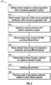
- FIG. 6 illustrates a flow chart 110 for operating the plasma separation system 10.
- the blood sample 130 (e.g., 100 ⁇ l) is added to the blood separation well 14 as illustrated in FIG. 7A .
- a pipet, or other similar device may be used to add the blood sample to the blood separation well 14.
- the blood sample wicks into the filter 40 and the separation membrane 42.
- the blood sample wicks into the filter 40 and the separation membrane 42 for a pre-determined time period.
- the blood sample may be allowed to wick into the filter 40 and the separation membrane 42 for approximately 5 - 45 seconds.
- the blood sample may wick into the filter 40 and the separation membrane 42 by capillary action.
- the presence of the one or more venting channels 68 may promote wicking of the blood sample by providing escape of gas from edges of the filter 40 and/or the separation membrane 42.
- the presence of microchannels 64 on the capillary surface 38 of the recess 30 may also promote capillary flow from the second side 56 of the separation membrane 42 into the channel 16 (shown in detail in FIG. 3 ).
- the negative pressure source 26 e.g., vacuum source
- the vacuum force assists the blood sample to proceed through the filter 40 providing filtered blood.
- the blood sample proceeds through the separation membrane 42 providing filtered plasma 132 as illustrated in FIG. 7B . It should be noted that prior to application of vacuum source to the blood separation well 14, a portion of the blood sample may proceed through the filter 40 and the separation membrane 42.
- the filtered plasma 132 may flow through the channel 16 and collect in the plasma collection vessel 18 as illustrated in FIG. 7C .
- the vacuum force may be maintained at a substantially constant level until all needed filtered plasma is collected in the plasma collection vessel 18 or may increase over time to a set-point.
- the vacuum force is caused to cease, such as by deactuating the negative pressure source 26 (e.g., vacuum source).
- the filtered plasma can be removed from the plasma collection vessel 18 such as by piercing the seal 80 of the plasma collection vessel 18.
- a pipet tip may pierce the seal 80 and filtered plasma may be removed from the plasma collection vessel 18.
- One or more assay may then be performed using the filtered plasma. Quantitative and/or qualitative assays may be performed using the filtered plasma. For example, as the pipet may be capable of collecting a determinate amount of filtered plasma, quantitative assays may be performed.
- a blood sample of 100 ⁇ L and 35% hematocrit (HCT) containing D-dimer at a concentration of 450 ng/ml may be added to the blood separation well 14 as illustrated in FIG. 7A .
- the filter 40 of the blood separation well 14 may be formed of VF2, and the separation membrane 42 may be formed of a polysulfone asymmetric membrane, for example.
- the blood sample may be allowed to wick into the filter 40 and separation membrane 42 for approximately 5-45 seconds.
- the negative pressure source 26 may be applied (e.g., between 0,34-13,79 kPa (0.05-2 psi) such that filtered plasma (e.g., approximately 20-25 ⁇ L) may be collected.
- the D-dimer concentration in the filtered plasma may then be measured (e.g., using a Siemens Stratus CS D-dimer immunoassay). In one example, the D-dimer concentration recovery for the filtered plasma, as compared to centrifugation was 100.8%.
- a blood sample of 100 ⁇ L and 42% HCT containing Tnl at a concentration of 100 pg/ml may be added to the blood separation well 14.
- the blood sample may be allowed to wick into the filter 40 and separation membrane 42 for approximately 5-45 seconds.
- the negative pressure source 26 is applied (e.g., between 0,34-13,79 kPa (0.05-2 psi) such that filter plasma (e.g., approximately 20 ⁇ L) may be collected.
- the Tnl concentration in the filtered plasma may then be measured (e.g., using Siemens Dimension EXL Tnl immunoassay).
- the Tnl concentration recovery for the filtered plasma, as compared to centrifugation was 86%.
- FIG. 8 illustrates another exemplary embodiment of a plasma separation system 10c.
- the plasma separation system 10c is similar to the plasma separation systems 10-10b illustrated in FIG. 1 , 4 and 5 respectively; however, the plasma separation system 10c applies positive force via a positive pressure source 140 upstream of the plasma collection vessel 18.
- the positive pressure source 140 is connected to a cap 142 positioned over the filter 40 within the blood separation well 14.
- the cap 142 is form fit over the filter 40 within the blood separation well 14.
- the cap 142 may include an outlet 144.
- the outlet 144 may connect to the positive pressure source 140.
- the positive pressure source 140 may provide between 0,34-13,79 kPa (0.05-2 psi) of positive pressure to the blood separation well 14 during use. The positive pressure may force the blood sample through the filter 40, separation membrane 42, and channel 16 into the plasma collection vessel 18.
- the positive pressure source 140 may be a syringe loaded with air. By forcing air through the outlet 144, positive pressure may be applied to the blood sample forcing the blood sample through the filter 40, separation membrane 42, and/or channel 16 to the plasma collection vessel 18.
- the outlet 24 downstream of the plasma collection vessel 18 may be used as a vent and opened as needed.
- inventive concept(s) disclosed herein are well adapted to carry out the objects and to attain the advantages mentioned herein, as well as those inherent in the inventive concept(s) disclosed herein. While the embodiments of the inventive concept(s) disclosed herein have been described for purposes of this disclosure, it will be understood that numerous changes may be made and readily suggested to those skilled in the art which are accomplished within the scope of the inventive concept(s) disclosed herein.
Landscapes
- Health & Medical Sciences (AREA)
- Life Sciences & Earth Sciences (AREA)
- Engineering & Computer Science (AREA)
- Biomedical Technology (AREA)
- Hematology (AREA)
- Physics & Mathematics (AREA)
- Chemical & Material Sciences (AREA)
- General Health & Medical Sciences (AREA)
- Pathology (AREA)
- Biophysics (AREA)
- Molecular Biology (AREA)
- Biochemistry (AREA)
- Medicinal Chemistry (AREA)
- Analytical Chemistry (AREA)
- Food Science & Technology (AREA)
- Urology & Nephrology (AREA)
- General Physics & Mathematics (AREA)
- Immunology (AREA)
- Ecology (AREA)
- Heart & Thoracic Surgery (AREA)
- Veterinary Medicine (AREA)
- Animal Behavior & Ethology (AREA)
- Public Health (AREA)
- Surgery (AREA)
- Medical Informatics (AREA)
- Vascular Medicine (AREA)
- Anesthesiology (AREA)
- Investigating Or Analysing Biological Materials (AREA)
- External Artificial Organs (AREA)
- Medicines Containing Material From Animals Or Micro-Organisms (AREA)
Description
- Plasma, rather than whole blood, is generally the preferred sample for many clinical diagnostic tests. For example, in HIV viral load detection, plasma is separated from whole blood as hemoglobin and other hemolysis products may interfere with detection of viral RNA. As hemoglobin and other hemolysis products may interfere with assay results, plasma may need to be non-hemolyzed.
- Within the industry, plasma is usually obtained by centrifuging whole blood separating red blood cells from plasma. The centrifuging process, however, may be slow and require large powered instrumentation. Additionally, once the centrifugation process has begun, the instrument is unavailable for use by another operator until completion of the process.
US 2012/0145619 A1 provides a method of collecting a plasma fraction, wherein the channel assembly includes a channel housing which is rotatably interconnected with a rotatable centrifuge rotor assembly. - Progress within the medical industry has been in the development of point-of-care systems to provide rapid and portable care. Because of time restraints, size of equipment, and one-operator use, centrifugation is generally impractical for use in such point-of-care diagnostic instruments. For example,
WO 2014/024066 A1 pertains to a system and method for separating plasma and/or serum from blood for bilirubin level estimation. Other separation methods including laminar-flow filtration or capillary-action based processes, however, are also expensive, complex, slow, require large volumes of blood, or may lead to unacceptable levels of hemolysis. InUS 5 147 606 A1 a capillary device is disclosed for analyzing blood using minimal sample volumes, e.g., fingerstick application. The plasma separation membrane to separate plasma from a blood sample is provided inUS 2012/0220047 . - To assist those of ordinary skill in the relevant art in making and using the subject matter hereof, reference is made to the appended drawings, which are not intended to be drawn to scale, and in which like reference numerals are intended to refer to similar elements for consistency. For purposes of clarity, not every component may be labeled in every drawing.
-
FIG. 1 is an exploded perspective view of an exemplary plasma separation system in accordance with the present disclosure. -
FIG. 2A is a cross-sectional view of the plasma separation system ofFIG 1 , taken along thelines 2A-2A inFIG. 1 . -
FIG. 2B is a cross-sectional view of an exemplary filter for use in the plasma separation system ofFIG. 1 , taken along thelines 2B-2B inFIG. 1 . -
FIG. 2C is a sectional view of an exemplary separation membrane for use in the plasma separation system ofFIG. 1 , taken along thelines 2C-2C inFIG. 1 . -
FIG. 2D is a sectional view of an exemplary adhesive member for use in the plasma separation system ofFIG. 1 , taken along thelines 2D-2D inFIG. 1 . -
FIG. 3 is a partial top down view of the plasma separation system ofFIG. 1 having the filter, the separation membrane, and the adhesive member removed. -
FIG. 4 is a partial perspective view of another version of an exemplary plasma separation system having a channel connected to a proximal end of a plasma collection vessel in accordance with the present disclosure. -
FIG. 5 is a top down view of yet another version of an exemplary plasma separation system having a plasma collection vessel with a serpentine channel in accordance with the present disclosure. -
FIG. 6 is a flow chart of an exemplary method for separating filtered plasma from a blood sample in accordance with the present disclosure. -
FIGS. 7A-7C collectively illustrate the use of an exemplary plasma separation system for separating filtered plasma from a blood sample in accordance with the method ofFIG. 6 . -
FIG. 8 is a cross-sectional view of another version of an exemplary plasma separation system having a pressure system connected to a blood separation well in accordance with the present disclosure - The following detailed description refers to the accompanying drawings. The same reference numbers in different drawings may identify the same or similar elements.
- As used in the description herein, the terms "comprises," "comprising," "includes," "including," "has," "having," or any other variations thereof, are intended to cover a non-exclusive inclusion. For example, unless otherwise noted, a process, method, article, or apparatus that comprises a list of elements is not necessarily limited to only those elements, but may also include other elements not expressly listed or inherent to such process, method, article, or apparatus.
- Further, unless expressly stated to the contrary, "or" refers to an inclusive and not to an exclusive "or". For example, a condition A or B is satisfied by one of the following: A is true (or present) and B is false (or not present), A is false (or not present) and B is true (or present), and both A and B are true (or present).
- In addition, use of the "a" or "an" are employed to describe elements and components of the embodiments herein. This is done merely for convenience and to give a general sense of the inventive concept. This description should be read to include one or more, and the singular also includes the plural unless it is obvious that it is meant otherwise. Further, use of the term "plurality" is meant to convey "more than one" unless expressly stated to the contrary.
- As used herein, any reference to "one embodiment," "an embodiment," "some embodiments," "one example," "for example," or "an example" means that a particular element, feature, structure or characteristic described in connection with the embodiment is included in at least one embodiment. The appearance of the phrase "in some embodiments" or "one example" in various places in the specification is not necessarily all referring to the same embodiment, for example.
- Referring now to the Figures, and in particular to
FIG. 1 , shown therein and designated byreference numeral 10 is an exemplaryplasma separation system 10 in accordance with the present disclosure. Generally, theplasma separation system 10 may provide separation of plasma from blood using a vacuum force, and without using centrifugation or laminar-flow filtration based filtration processes. The separation of plasma from blood may be with minimal hemolysis and within a relatively short amount of time (e.g., 10-90 seconds) as compared to processes used currently within the industry. In some embodiments, the plasma may be further used in one or more point-of-care assays. - The
plasma separation system 10 includes ahousing 12 supporting or encompassing a blood separation well 14 connected via afirst channel 16 to aplasma collection vessel 18. Thehousing 12 supports or encompasses asecond channel 22 connecting theplasma collection vessel 18 to anoutlet port 24 downstream of theplasma collection vessel 18. Theplasma separation system 10 may also include anegative pressure source 26 that can be attached to theoutlet port 24. In this instance, theoutlet port 24 can be configured to allow for thenegative pressure source 26 to be attached thereto assist in enabling the operation of theplasma separation system 10. - Generally, in the
plasma separation system 10, blood is added to the blood separation well 14. Negative pressure (e.g., vacuum pressure) is applied by thenegative pressure source 26 to theoutlet port 24, which also causes a vacuum to form in the blood separation well 14. Using a combination of capillary action and negative pressure, plasma is separated from the blood. The magnitude of the negative pressure may be controlled to prevent hemolysis and/or leakage of cellular material. The separated plasma is collected in theplasma collection vessel 18. - In some embodiments, the
plasma separation system 10 may be a single-use system. Alternatively, one or more components of theplasma separation system 10 may be disposable such that theplasma separation system 10 may be a multi-use system. For example, in some embodiments, after a first blood sample is separated, one ormore channels plasma collection vessel 18 and components of the blood separation well 14 may be removed, disposed of, and replaced for use with a second blood sample. - The
housing 12 may be formed of materials including, but not limited to, glass, plastic, and/or the like. The shape and size of thehousing 12 may be dependent on shape and/or size of the blood separation well 14,channels housing 12 that is shown inFig. 1 is a unitary integral device that is shaped to form the blood separation well 14,channels plasma collection vessel 18. It should be understood that thehousing 12 can be constructed of separate components which are connected together so that the blood separation well 14,channels plasma collection vessel 18 communicate with each other. Generally, the size of thehousing 12 may be minimized and determinate on an amount of plasma that is desired (e.g., 10-20 µL) to be extracted from a blood sample. Thehousing 12 may include asurface 28. - The blood separation well 14 is positioned to intersect the
surface 28 of thehousing 12 such that thesurface 28 at least partially surrounds the blood separation well 14. The blood separation well 14 includes arecess 30 intersecting thesurface 28 of thehousing 12 as illustrated inFIGS. 1 and2 and in this instance thesurface 28 may form a rim surrounding therecess 30. Therecess 30 may include aproximal end 32 and adistal end 34 with awall 36 spanning the length of theproximal end 32 to thedistal end 34. Theproximal end 32 may include acapillary surface 38 in which microchannels are formed in theproximal end 32 as discussed in more detail below with respect toFIG. 3 . - The
plasma separation device 10 is also provided with afilter 40, aseparation membrane 42, and anadhesive member 44. Thefilter 40, theseparation membrane 42 and theadhesive member 44 are stacked on thecapillary surface 38 and disposed within therecess 30 such that thefilter 40 is below thesurface 28 of thehousing 12 and fully disposed within therecess 30. For example, in some embodiments, theadhesive member 44 may be positioned on thecapillary surface 38 with theseparation membrane 42 and thefilter 40 positioned thereon, respectively. Thefilter 40 andseparation membrane 42 are pressure fit (also known as a "press fit") within therecess 30. - The size and shape of the
recess 30 may be dependent on the size and shape of thefilter 40, theseparation membrane 42, and/or theadhesive member 44. For example, in some embodiments, the size and shape of therecess 30 may be circular as thefilter 40,separation membrane 42, andadhesive member 44 are circular. The shape, however, may be any shape including, but not limited to, rectangular, triangular, or any fanciful shape. The volume of therecess 30, including the height and/or length ofwall 36 may be dependent on thicknesses and/or the widths of one or more of thefilter 40,separation membrane 42, andadhesive member 44. Generally, thefilter 40,separation membrane 42 and theadhesive member 44 may be positioned within therecess 30 such that each remains between theproximal end 32 and thedistal end 34 of therecess 30. Further, although thewall 36 is depicted as a straight wall, it should be understood that in some embodiments, thewall 36 can be stepped. - In some embodiments, one or more additional layers may be positioned on a
first side 48 of thefilter 40 to hold thefilter 40 andseparation membrane 42 within the blood separation well 14. For example, in one example, a plastic O-ring may be positioned on thefirst surface 48 of thefilter 40 to hold thefilter 40 andseparation membrane 42 within the blood separation well 14. In another example, a cap (e.g., plastic formed cap) may be positioned adjacent or proximal to thefirst side 48 of thefilter 40 and span the length of the blood separation well 14. In some embodiments, the cap may be vented to allow for escape of gas to the outside environment. The cap may serve to hold thefilter 40 in close proximity to theseparation membrane 42. In one example, as blood wicks into thefilter 40 during use, thefilter 40 may expand in size such that the cap retains thefilter 40 within the blood separation well 14. To that end, thefilter 40 may expand in the direction of theseparation membrane 42 positioning thefilter 40 in close proximity or even in contact with theseparation membrane 42. - The
filter 40 is formed of one or more layers 46. Eachlayer 46 may include thefirst side 48 and asecond side 50 generally opposite of thefirst side 48. Generally, blood is provided onto and contacts thefirst side 48 of thefilter 40 and passes through thelayer 46 of thefilter 40 such that filtered blood emerges on thesecond side 50. The filtered blood may include plasma and a portion of red blood cells that managed to pass through thelayer 46. Some of the red blood cells will be captured within thelayer 46 of thefilter 40. - In other words, the
filter 40 generally removes a portion of the red blood cells from the blood and also may reduce separation burden of theseparation membrane 42. For example, thefilter 40 may remove red blood cells (e.g., up to 70% of red blood cells) within the blood sample. The removal of a significant portion of red blood cells may aid the flow of the filtered blood through theseparation membrane 42 and also reduce clogging of theseparation membrane 42. - Each
layer 46 may be formed of materials including, but not limited to, glass fibers, polyester fibers, cellulose fibers, and/or the like. For example, one ormore filters 40 may be a commercially available filter under the trade name designations of VF1, VF2 and GFB, manufactured and distributed by Whatman, having a location in Maidstone Kent. For example, in some embodiments, one ormore filters 40 may be a 9.5 mm disc of Whatman VF2 glass fiber. - The
second side 50 of thefilter 40 is in proximity to or contact theseparation membrane 42. Generally, theseparation membrane 42 may remove the remaining red blood cells from the filtered blood providing filtered plasma. The filtered plasma may be essentially cell-free in that the filtered plasma includes minimal cellular debris. For example, hemoglobin content with the filtered plasma may be comparable to plasma obtained by centrifuge techniques currently known within the industry. - In some embodiments not part of the invention, the
plasma separation system 10 may solely comprise theseparation membrane 42 without the use of thefilter 40. For example, the blood may be filtered solely through theseparation membrane 42 providing filtered plasma using the methods as described herein. - The
separation membrane 42 may be formed of one or more layers 52. Eachlayer 52 may have afirst side 54 and asecond side 56. Generally, the filtered blood contacts thefirst side 54 of theseparation membrane 42 passing through thelayer 52 of the separation membrane such that filtered plasma emerges on thesecond side 56. - The
separation membrane 42 may be formed of materials including, but not limited to, nylon, polysulfone, polycarbonate and/or the like. For example, in some embodiments, theseparation membrane 42 may be an ion-tracked etched membrane. - In some embodiments, the
separation membrane 42 may be an asymmetric membrane. For example, theseparation membrane 42 may be formed having at least a first set of pores and a second set of pores, with the first set of pores and the second set of pores being different sizes. Generally, larger pores may be formed on thefirst side 54 of theseparation membrane 42 and smaller pores may be formed on thesecond side 56 of theseparation membrane 42 such that the filtered blood flows through the larger pores to the small pores. This may reduce blockage of red blood cells within theseparation membrane 42. - In some embodiments, one or both of the
filter 40 and/orseparation membrane 42 may be treated with one or more blocking agents and/or surfactants. Treatment with blocking agents and/or surfactant may enhance analyte recovery and/or plasma separation efficiency. Surfactants may include, but are not limited to, Tween-20, and/or the like. - By treating with one or more blocking agents, the
filter 40 and/orseparation membrane 42 may be made more or less hydrophilic, more or less hydrophobic, more or less susceptible to protein adsorption, more or less positively charged, more or less negatively charged and/or the like. For example, in some embodiments, thefilter 40 and/orseparation membrane 42 may be treated with PAMAM dendrimers, Merquat, or other polycations. Blocking agents may include, but are not limited to bovine serum albumin, Seablock, gelatin, and/or the like. - The
second surface 56 of theseparation membrane 42 may contact theadhesive member 44. In some embodiments, theadhesive member 44 may prevent leakage of blood cells around the perimeter of theseparation membrane 42. - The
adhesive member 44 may include afirst surface 58 and asecond surface 60 with thefirst surface 58 contacting thesecond surface 56 of theseparation membrane 42 and thesecond surface 60 adhered to at least a portion of thecapillary surface 38 of therecess 30. Generally, theadhesive member 44 aids in holding theseparation membrane 42 within therecess 30. To that end, in some embodiments, eachsurface adhesive member 44 may include an adhesive material. Adhesive material may include, but is not limited to, polyethylene terephthalate (PET) with silicone adhesive, and/or the like. For example, theadhesive member 44 may be a double-sided PET adhesive O-ring as illustrated inFIGS. 2A and2D . In some embodiments, theadhesive member 44 may be integral to the blood separation well 14 or adhered to thewall 36 of therecess 30. - Size and shape of the
adhesive member 44 may be dependent on the size and shape of theseparation membrane 42 such that theseparation membrane 42 may be positioned within the blood separation well 14 and leakage of filtered blood about edges of theseparation membrane 42 may be minimized or eliminated. - The size and shape of the
adhesive member 44 may be determined such that theseparation membrane 42 is placed in close contact with thecapillary surface 38 of therecess 30 of the blood separation well 14 while preventing leakage of blood within the blood separation well 14. In some embodiments, the shape of theadhesive member 44 may include anopening 62. Theopening 62 may provide for flow of the filtered plasma to flow from thesecond surface 56 of theseparation membrane 42 to thecapillary surface 38 of therecess 30. For example, in some embodiments, theadhesive member 44 may be formed as an O-ring, or any fanciful shape providing adirect opening 62 for flow of filtered plasma from thesecond surface 56 of theseparation membrane 42 to thecapillary surface 38 of therecess 30. Additionally, in some embodiments, the material of theadhesive member 44 may be formed of a mesh-type material. - Referring to
FIGS. 2A and3 , thecapillary surface 38 of therecess 30 of the blood separation well 14 includes one ormore microchannels 64.Microchannels 64 may encourage capillary flow of the filtered plasma.Microchannels 64 may form any pattern capable of enhancing capillary flow of the filtered plasma through the blood separation well 14. For example, inFIGS. 1 and3 , eightmicrochannels 64 are used to form a concentric pattern having a plurality of radial microchannels connecting at acentral axis 66. Although eightmicrochannels 64 are illustrated inFIGS. 1 and3 , it should be apparent to one skilled in the art that any number ofmicrochannels 64 may be used so long assuch microchannels 64 are positioned within the confines of thecapillary surface 38. Additionally, one or more tributaries may be included within the concentric pattern. It should be noted that thecapillary surface 38, in some embodiments not part of the invention, may not includemicrochannels 64 as capillary flow may still occur withoutsuch microchannels 64. - In some embodiments, one or
more venting channels 68 may be positioned within therecess 30 of the blood separation well 14. For example, inFIGS. 1 and3 , four ventingchannels 68 are provided within therecess 30 of the blood separation well 14 extending from thecapillary surface 38 to thesurface 28. Ventingchannels 68 may provide for venting of gas (e.g., air) within the blood separation well 14. For example, gas entering thefilter 40 and/orseparation membrane 42 may exit the blood separation well 14 through the one ormore venting channels 68. - The filtered plasma may flow from the blood separation well 14 to the
channel 16. Thechannel 16 may include afirst outlet 70 connected to theplasma collection vessel 18. In some embodiments, thechannel 16 may also include asecond outlet 72. Generally, thesecond outlet 72 may be blocked during operation of theplasma separation system 10 to cause the vacuum force to be directed into the blood separation well via thechannel 16. Thesecond outlet 72 may be capable of being selectively opened to provide for removal of any additional filtered blood and/or filtered plasma from within the blood separation well 14 and/orchannel 16. - The filtered plasma flows through the
channel 16 and through thefirst outlet 70 to theplasma collection vessel 18. Theplasma collection vessel 18 may have aproximal end 74 and adistal end 76 connected by a taperedwall 78. For example, the width of theplasma collection vessel 18 may increase from theproximal end 74 to thedistal end 76. Although the shape of theplasma collection vessel 18 is shown as conical, it should be apparent that theplasma collection vessel 18 may be formed in other shapes (e.g., cylindrical). Generally, theplasma collection vessel 18 may be formed such that the amount of volume where the filtered plasma collects reduces dead volume. For example, the shape of theplasma collection vessel 18 may be formed such that the filtered plasma collects in an area wherein recovery of the filtered plasma by a pipette or other collection means may be maximized (e.g., collection of 10-20 µL of filtered plasma). - Generally, the
first outlet 70 may be positioned below theoutput port 24 and near theproximal end 74 of theplasma collection vessel 18. Collection of filtered plasma may be in aportion 79 positioned below thefirst outlet 70, e.g., between thefirst outlet 70 and theproximal end 74 of theplasma collection vessel 18 as illustrated inFIG. 2A . - The
plasma collection vessel 18 includes aseal 80. Theseal 80 covers thedistal end 76 of theplasma collection vessel 18 so that vacuum force applied to theoutput port 24 of thechannel 22 is directed through theplasma collection vessel 18 and into thechannel 16. In some embodiments, theseal 80 is formed of pierceable material. For example, theseal 80 may be formed of materials capable of being pierced by a pipet tip or similar mechanism for collection of plasma from theplasma collection vessel 18. Such materials may include, but are not limited to, acetate, polyethylene, foil and/or the like. - The
plasma collection vessel 18 is connected to thechannel 22. Thechannel 22 is positioned above thechannel 16, and in proximity to thedistal end 76 of theplasma collection vessel 18, e.g., between thechannel 16 and thedistal end 76. Thechannel 22 connects theplasma collection vessel 18 to thenegative pressure source 26 via theoutlet port 24. In some embodiments, theoutlet port 24 of thechannel 22 may include a fitted tube or luer connection at which thenegative pressure source 26 is connected. - The
negative pressure source 26 may be any source capable of providing force between approximately 0,34-13,79 kPa (0.05-2 psi). For example, thenegative pressure source 26 may include, but is not limited to, a pump, a syringe pump, a vacuum pump, a suction pump, and/or the like. Generally, thenegative pressure source 26 may be capable of being controlled such that plasma may be collected without hemolysis and/or free of cellular material from the blood. For example, by controlling the force of thenegative pressure source 26 within the boundaries discussed above, the risks of damage to the plasma may be reduced such that the blood may not hemolyze and/or cells may not deform (i.e., pass through the separation membrane 42). - Control of the
negative pressure source 26 may provide for a fixed flow rate and volume. For example, in some embodiments, one or more pressure sensors or monitors may be used to control thenegative pressure source 26. In another example, displacement speed of a syringe may control the rate and volume of thenegative pressure source 26. -
FIG. 4 illustrates another exemplary embodiment of aplasma separation system 10a. Similar to theplasma separator system 10 ofFIG. 1 , theplasma separation system 10a includes thehousing 12 supporting or encompassing the blood separation well 14. The blood separation well 14 is connected via afirst channel 16a to aplasma collection vessel 18a such that filtered plasma enters theplasma collection vessel 18a from aproximal end 94 of theplasma collection vessel 18a. Asecond channel 22 connects theplasma collection vessel 18a to anoutlet port 24 downstream of theplasma collection vessel 18a. Theoutlet port 24 may allow for a negative pressure source 26 (e.g., vacuum source) to be attached to theplasma separator system 10a. - The
channel 16a may be implemented in a variety of manners such that thechannel 16a connects theplasma collection vessel 18a to theproximal end 94 of theplasma collection vessel 18a. For example, thechannel 16a may include a variety of linear segments that are interconnected as shown inFIG. 4 . In the example depicted inFIG. 4 , thechannel 16a includes afirst portion 82 and asecond portion 84 that may be in parallel alignment connected by athird portion 86 extending between thefirst portion 82 and thesecond portion 84. In the example shown, thethird portion 86 extends normally to thefirst portion 82 and thesecond portion 84 and vertically within thehousing 12. Although thechannel 16a includescorners first portion 82 and thesecond portion 84 with thethird portion 86, it should be noted, thecorners 88 may include rounded edges. Additionally, thethird portion 86 may be positioned at an angle relative to thefirst portion 82 and thesecond portion 84 such that thethird portion 86 provides a sloped connection between thefirst portion 82 and thesecond portion 84. Afourth portion 92 of thechannel 16a may provide aninlet 94 into theproximal end 94 of theplasma collection vessel 18a. - Generally, in the
plasma separation system 10a, blood is added to the blood separation well 14. Vacuum pressure may be applied via theoutlet port 24. Using a combination of capillary action and vacuum pressure, plasma may be separated from the blood. The plasma may enter and collect at theproximal end 94 of theplasma collection vessel 18a. The vacuum pressure may be controlled to prevent hemolysis and/or leakage of cellular material. -
FIG. 5 illustrates another exemplary embodiment of aplasma separation system 10b which is similar in construction to theplasma separation systems FIGS. 1 and4 with the exception that thatplasma separation system 10b includes aplasma collection vessel 18b in the form of aserpentine channel 96, rather than a well. Since the volume of the serpentine may be controlled by the length of theserpentine channel 96, thesystem 10b can be used to meter the plasma. Theserpentine channel 96 can be readily integrated with other standard microfluidic features such as valves and reaction wells for performing quantitative and qualitative assays. The number of curves, the configuration and/or the length of theserpentine channel 96 may be determined based on the assay of interest. -
FIGS. 6 and7A-7C illustrate an exemplary method for operating theplasma separator system 10 ofFIG. 1 . In particular,FIG. 6 illustrates aflow chart 110 for operating theplasma separation system 10. - To separate plasma from red and white blood cells in a blood sample, in a
step 112, the blood sample 130 (e.g., 100 µl) is added to the blood separation well 14 as illustrated inFIG. 7A . In some embodiments, a pipet, or other similar device, may be used to add the blood sample to the blood separation well 14. - In a
step 114, the blood sample wicks into thefilter 40 and theseparation membrane 42. In some embodiments, the blood sample wicks into thefilter 40 and theseparation membrane 42 for a pre-determined time period. For example, in one non-limiting example, the blood sample may be allowed to wick into thefilter 40 and theseparation membrane 42 for approximately 5 - 45 seconds. - In some embodiments, the blood sample may wick into the
filter 40 and theseparation membrane 42 by capillary action. In one non-limiting example, the presence of the one or more venting channels 68 (shown inFIG. 3 ) may promote wicking of the blood sample by providing escape of gas from edges of thefilter 40 and/or theseparation membrane 42. Further, the presence ofmicrochannels 64 on thecapillary surface 38 of therecess 30 may also promote capillary flow from thesecond side 56 of theseparation membrane 42 into the channel 16 (shown in detail inFIG. 3 ). - In a
step 116, the negative pressure source 26 (e.g., vacuum source) is actuated to apply the vacuum force to the blood separation well 14 via theoutlet port 24. In astep 118, the vacuum force assists the blood sample to proceed through thefilter 40 providing filtered blood. In astep 120, the blood sample proceeds through theseparation membrane 42 providing filteredplasma 132 as illustrated inFIG. 7B . It should be noted that prior to application of vacuum source to the blood separation well 14, a portion of the blood sample may proceed through thefilter 40 and theseparation membrane 42. - In a
step 122, the filteredplasma 132 may flow through thechannel 16 and collect in theplasma collection vessel 18 as illustrated inFIG. 7C . The vacuum force may be maintained at a substantially constant level until all needed filtered plasma is collected in theplasma collection vessel 18 or may increase over time to a set-point. - In a
step 124, the vacuum force is caused to cease, such as by deactuating the negative pressure source 26 (e.g., vacuum source). In astep 126, the filtered plasma can be removed from theplasma collection vessel 18 such as by piercing theseal 80 of theplasma collection vessel 18. For example, a pipet tip may pierce theseal 80 and filtered plasma may be removed from theplasma collection vessel 18. One or more assay may then be performed using the filtered plasma. Quantitative and/or qualitative assays may be performed using the filtered plasma. For example, as the pipet may be capable of collecting a determinate amount of filtered plasma, quantitative assays may be performed. - In one example, a blood sample of 100 µL and 35% hematocrit (HCT) containing D-dimer at a concentration of 450 ng/ml may be added to the blood separation well 14 as illustrated in
FIG. 7A . Thefilter 40 of the blood separation well 14 may be formed of VF2, and theseparation membrane 42 may be formed of a polysulfone asymmetric membrane, for example. Using the process detailed inFIGS. 6 and7 , the blood sample may be allowed to wick into thefilter 40 andseparation membrane 42 for approximately 5-45 seconds. Thenegative pressure source 26 may be applied (e.g., between 0,34-13,79 kPa (0.05-2 psi) such that filtered plasma (e.g., approximately 20-25 µL) may be collected. The D-dimer concentration in the filtered plasma may then be measured (e.g., using a Siemens Stratus CS D-dimer immunoassay). In one example, the D-dimer concentration recovery for the filtered plasma, as compared to centrifugation was 100.8%. - In another example, a blood sample of 100 µL and 42% HCT containing Tnl at a concentration of 100 pg/ml may be added to the blood separation well 14. Using the process detailed in
FIGS. 6 and7 , the blood sample may be allowed to wick into thefilter 40 andseparation membrane 42 for approximately 5-45 seconds. Thenegative pressure source 26 is applied (e.g., between 0,34-13,79 kPa (0.05-2 psi) such that filter plasma (e.g., approximately 20 µL) may be collected. The Tnl concentration in the filtered plasma may then be measured (e.g., using Siemens Dimension EXL Tnl immunoassay). In one example, the Tnl concentration recovery for the filtered plasma, as compared to centrifugation was 86%. -
FIG. 8 illustrates another exemplary embodiment of aplasma separation system 10c. Theplasma separation system 10c is similar to the plasma separation systems 10-10b illustrated inFIG. 1 ,4 and 5 respectively; however, theplasma separation system 10c applies positive force via apositive pressure source 140 upstream of theplasma collection vessel 18. In particular, thepositive pressure source 140 is connected to acap 142 positioned over thefilter 40 within the blood separation well 14. - In some embodiments, the
cap 142 is form fit over thefilter 40 within the blood separation well 14. Thecap 142 may include anoutlet 144. Theoutlet 144 may connect to thepositive pressure source 140. Thepositive pressure source 140 may provide between 0,34-13,79 kPa (0.05-2 psi) of positive pressure to the blood separation well 14 during use. The positive pressure may force the blood sample through thefilter 40,separation membrane 42, andchannel 16 into theplasma collection vessel 18. - In some embodiments, the
positive pressure source 140 may be a syringe loaded with air. By forcing air through theoutlet 144, positive pressure may be applied to the blood sample forcing the blood sample through thefilter 40,separation membrane 42, and/orchannel 16 to theplasma collection vessel 18. In this embodiment, theoutlet 24 downstream of theplasma collection vessel 18 may be used as a vent and opened as needed. - From the above description, it is clear that the inventive concept(s) disclosed herein are well adapted to carry out the objects and to attain the advantages mentioned herein, as well as those inherent in the inventive concept(s) disclosed herein. While the embodiments of the inventive concept(s) disclosed herein have been described for purposes of this disclosure, it will be understood that numerous changes may be made and readily suggested to those skilled in the art which are accomplished within the scope of the inventive concept(s) disclosed herein.
Claims (8)
- An apparatus, comprising:a housing (12) supporting or encompassing a blood separation well (14) for collection of a blood sample (130), the blood separation well (14) having a recess (30) intersecting a surface (28) of the housing (12), wherein the surface of the recess is defined further as a capillary surface (38) having at least one microchannel;a separation membrane (42) positioned on the surface of the recess (30) for filtration of the blood sample to provide filtered plasma (132);a plasma collection vessel (18) configured to collect filtered plasma; a first channel (16) connecting the blood separation well (14) to the plasma collection vessel (18) proximate to the surface of the recess (30); and,a second channel (22) connecting the plasma collection vessel (18) to a first outlet port (24), and a filter (40) positioned within the recess (30, the second side (50) of the filter (40) being in proximity to or in contact with the separation membrane (42), wherein the filter (40) is formed of one or more layers (46),a seal (80) is positioned on a distal end (76) of the plasma collection vessel (18), wherein the seal (80) is formed of a pierceable material;the second channel (22) is positioned above the first channel (16) and in proximity to the distal end (76) of the plasma collection vessel (18) such that, when a negative pressure force is applied to the first outlet port (24) of the second channel (22), filtered plasma (132) is drawn into the collection vessel (18), wherein the first channel (16), the plasma collection vessel (18), and the second channel (22) are configured to convey the negative pressure force applied to the first outlet port (24) to the surface of the recess (30),characterized in thatan adhesive member is disposed within the recess and positioned on the capillary surface, with the separation membrane and the filter positioned thereon, respectively, wherein the filter (40), the separation membrane (42) and the adhesive member (44) are stacked on the capillary surface (38) and wherein the filter (40) and the separation membrane (42) are pressure fit within the recess (30).
- The apparatus of claim 1, wherein the capillary surface (38) has a plurality of microchannels (64) forming a concentric pattern in the capillary surface (38), the concentric pattern having a set of radial microchannels (64) projecting from a location.
- The apparatus of claim 1or 2, further comprising a vacuum source connected to the second channel (22) at the outlet port (24), wherein the vacuum source is a syringe pump, the syringe pump providing a negative pressure force between 0,34 to 13,79 kPa.
- An apparatus, comprising:a housing (12) supporting or encompassing a blood separation well (14) for collection of a blood sample (130), the blood separation well (14) having a recess (30) intersecting a surface (28) of the housing (12);a separation membrane (42) positioned on the surface of the recess (30) for filtration of the blood sample to provide filtered plasma (132), wherein the surface of the recess is defined further as a capillary surface having at least one microchannel;a plasma collection vessel (18) configured to collect filtered plasma; a first channel (16) connecting the blood separation well (14) to the plasma collection vessel (18) proximate to the surface of the recess (30); and,a second channel (22) connecting the plasma collection vessel (18) to a first outlet port (24), and a filter (40) positioned within the recess (30), the second side (50) of the filter (40) being in proximity to or in contact with the separation membrane (42), wherein the filter (40) is formed of one or more layers (46),characterized in thatan adhesive member is disposed within the recess and positioned on the capillary surface with the separation membrane and the filter positioned thereon, respectively, and wherein the filter (40) and the separation membrane (42) are press fit within the recess (30), andthe second channel (22) is positioned above the first channel (16) and in proximity to a distal end (76) of the plasma collection vessel (18), a cap (142) is form fit over the filter (40) within the blood separation well (14) such that when a positive pressure force is applied via a positive pressure source (140) connected to the cap (142), the blood sample is forced through the filter (40), the separation membrane (42) and the channel (16) into the plasma collection vessel (18).
- The apparatus of claim 4, wherein the capillary surface (38) has a plurality of microchannels (64) forming a concentric pattern in the capillary surface (38), the concentric pattern having a set of radial microchannels (64) projecting from a location.
- The apparatus of claim 4, further comprising a seal (80) positioned on the distal end (76) of the plasma collection vessel (18), wherein the seal (80) is formed of a pierceable material.
- A kit comprising:the apparatus as claimed in any of claims 1 to 6;
anda vacuum source (26) configured to connect to the outlet port (24), the vacuum source configured to provide a negative pressure between 0,34-13,79 kPa to the outlet port (24), ora positive pressure source (140) configured to connect to a cap (142) positioned over the filter (40) within the blood separation well (14), the pressure source configured to provide a positive pressure between 0,34-13,79 kPa. - A method comprising:
adding a blood sample (130) to the blood separation well (14) of an apparatus according to claim 1, and actuating the vacuum source to apply a vacuum force to the blood separation well (14) via the outlet port (24) to enhance flow of plasma from the blood sample (130) through the filter (40) and separation membrane (42) providing filtered plasma (132), and to draw the filtered plasma (132) through the first channel (16) into the plasma collection vessel (18), wherein the vacuum source is controlled to prevent hemolysis and/or leakage of cellular material.
Applications Claiming Priority (2)
| Application Number | Priority Date | Filing Date | Title |
|---|---|---|---|
| US201462031908P | 2014-08-01 | 2014-08-01 | |
| PCT/US2015/042838 WO2016019113A1 (en) | 2014-08-01 | 2015-07-30 | Vacuum-assisted plasma separation |
Publications (3)
| Publication Number | Publication Date |
|---|---|
| EP3174573A1 EP3174573A1 (en) | 2017-06-07 |
| EP3174573A4 EP3174573A4 (en) | 2017-10-04 |
| EP3174573B1 true EP3174573B1 (en) | 2025-02-19 |
Family
ID=55218307
Family Applications (1)
| Application Number | Title | Priority Date | Filing Date |
|---|---|---|---|
| EP15826556.1A Active EP3174573B1 (en) | 2014-08-01 | 2015-07-30 | Vacuum-assisted plasma separation |
Country Status (7)
| Country | Link |
|---|---|
| US (3) | US10989706B2 (en) |
| EP (1) | EP3174573B1 (en) |
| JP (1) | JP6715236B2 (en) |
| CA (1) | CA2956710C (en) |
| IL (1) | IL249853B (en) |
| MX (1) | MX389321B (en) |
| WO (1) | WO2016019113A1 (en) |
Families Citing this family (15)
| Publication number | Priority date | Publication date | Assignee | Title |
|---|---|---|---|---|
| JP6778827B2 (en) | 2017-01-30 | 2020-11-04 | ヴィヴェバイオ サイエンティフィック,エルエルシー | Plasma separator |
| JP2021500883A (en) | 2017-10-27 | 2021-01-14 | ジュノ ダイアグノスティックス,インク. | Devices, systems, and methods for ultratrace liquid biopsy |
| CA3095030A1 (en) | 2018-03-30 | 2019-10-03 | Juno Diagnostics, Inc. | Deep learning-based methods, devices, and systems for prenatal testing |
| US11007526B2 (en) * | 2018-07-06 | 2021-05-18 | Qorvo Us, Inc. | Capless sample well port for a cartridge |
| EP3890871A4 (en) | 2018-12-07 | 2022-01-26 | Siemens Healthcare Diagnostics Inc. | DEVICE WITH FLUID COMPONENT EVALUATION FEATURE |
| FI129091B (en) * | 2019-02-12 | 2021-06-30 | Magnasense Tech Oy | Sample handling device |
| CN109925884A (en) * | 2019-04-27 | 2019-06-25 | 南京岚煜生物科技有限公司 | A kind of method of Whole Blood Filtration and filter membrane structure for Whole Blood Filtration |
| US12399169B2 (en) | 2019-07-19 | 2025-08-26 | Siemens Healthcare Diagnostics Inc. | Tangent flow hemolysis detection blood testing device |
| US12097494B2 (en) * | 2020-09-17 | 2024-09-24 | Mayo Foundation For Medical Education And Research | Methods, devices, and systems for detecting two or more analytes within small volumes |
| KR102481011B1 (en) * | 2022-04-08 | 2022-12-26 | 정대서 | Lab-on-a-chip for field analysis using whole blood |
| JP2025524528A (en) * | 2022-06-30 | 2025-07-30 | シーメンス・ヘルスケア・ダイアグノスティックス・インコーポレイテッド | Acoustophoretic analysis device and method |
| KR102867058B1 (en) * | 2022-09-26 | 2025-10-01 | (주)페블아이 | Blood separation bio-chip for Point-of-care testing |
| KR102938643B1 (en) * | 2023-06-19 | 2026-03-13 | (주)페블아이 | Portable bio-chip for Point-of-care testing |
| US12584902B2 (en) | 2023-12-10 | 2026-03-24 | Instrumentation Laboratory Company | Acoustic separation of a test sample |
| KR20260029788A (en) * | 2024-08-26 | 2026-03-05 | (주)페블아이 | All-in-one portable bio-chip for Point-of-care testing |
Citations (3)
| Publication number | Priority date | Publication date | Assignee | Title |
|---|---|---|---|---|
| US4872988A (en) * | 1988-02-02 | 1989-10-10 | Culkin Joseph B | Method and device for separation of colloidal suspensions |
| EP0785430A1 (en) * | 1996-01-19 | 1997-07-23 | Fuji Photo Film Co., Ltd. | Separation of plasma or serum sample from whole blood |
| WO2007000986A1 (en) * | 2005-06-27 | 2007-01-04 | Sekisui Chemical Co., Ltd. | Blood-separating filter device and vacuum sampling tube |
Family Cites Families (13)
| Publication number | Priority date | Publication date | Assignee | Title |
|---|---|---|---|---|
| US5147606A (en) * | 1990-08-06 | 1992-09-15 | Miles Inc. | Self-metering fluid analysis device |
| ATE516879T1 (en) | 2002-02-12 | 2011-08-15 | Cellectricon Ab | SYSTEMS AND METHODS FOR QUICKLY CHANGE THE SOLUTION ENVIRONMENT OF SENSORS |
| CA2504603C (en) | 2002-11-19 | 2012-11-13 | Sekisui Chemical Co., Ltd. | Plasma or serum separation membrane and filter apparatus including the plasma or serum separation membrane |
| GB0525997D0 (en) | 2005-12-21 | 2006-02-01 | Oxford Biosensors Ltd | Micro-fluidic structures |
| US8123713B2 (en) | 2008-08-12 | 2012-02-28 | Caridian Bct, Inc. | System and method for collecting plasma protein fractions from separated blood components |
| CN102481573A (en) | 2009-09-01 | 2012-05-30 | 皇家飞利浦电子股份有限公司 | Fluid filtering device |
| WO2012015926A2 (en) | 2010-07-27 | 2012-02-02 | Northwestern University | Devices and methods for filtering blood plasma |
| EP2637788A1 (en) * | 2010-11-10 | 2013-09-18 | Boehringer Ingelheim Microparts GmbH | Device for filtering blood |
| US9157903B2 (en) | 2011-02-25 | 2015-10-13 | Honeywell International Inc. | Microfluidic separation of plasma for colormetric assay |
| US9182326B2 (en) | 2011-03-24 | 2015-11-10 | Boehringer Ingelheim Microparts Gmbh | Device and method for filtering blood |
| JP2014516644A (en) | 2011-04-29 | 2014-07-17 | セブンス センス バイオシステムズ,インコーポレーテッド | Devices and methods for collection and / or manipulation of blood spots or other body fluids |
| WO2014024066A1 (en) * | 2012-08-08 | 2014-02-13 | Koninklijke Philips N.V. | Method and apparatus for separating plasma from blood for bilirubin level estimation. |
| EP2695652A1 (en) | 2012-08-09 | 2014-02-12 | F. Hoffmann-La Roche AG | System for separating plasma from blood |
-
2015
- 2015-07-30 US US15/329,795 patent/US10989706B2/en active Active
- 2015-07-30 MX MX2017001368A patent/MX389321B/en unknown
- 2015-07-30 JP JP2017505541A patent/JP6715236B2/en active Active
- 2015-07-30 CA CA2956710A patent/CA2956710C/en active Active
- 2015-07-30 EP EP15826556.1A patent/EP3174573B1/en active Active
- 2015-07-30 WO PCT/US2015/042838 patent/WO2016019113A1/en not_active Ceased
-
2016
- 2016-12-29 IL IL249853A patent/IL249853B/en unknown
-
2021
- 2021-04-09 US US17/226,464 patent/US11371983B2/en active Active
- 2021-04-09 US US17/226,492 patent/US12487232B2/en active Active
Patent Citations (3)
| Publication number | Priority date | Publication date | Assignee | Title |
|---|---|---|---|---|
| US4872988A (en) * | 1988-02-02 | 1989-10-10 | Culkin Joseph B | Method and device for separation of colloidal suspensions |
| EP0785430A1 (en) * | 1996-01-19 | 1997-07-23 | Fuji Photo Film Co., Ltd. | Separation of plasma or serum sample from whole blood |
| WO2007000986A1 (en) * | 2005-06-27 | 2007-01-04 | Sekisui Chemical Co., Ltd. | Blood-separating filter device and vacuum sampling tube |
Also Published As
| Publication number | Publication date |
|---|---|
| JP6715236B2 (en) | 2020-07-01 |
| US20210231642A1 (en) | 2021-07-29 |
| WO2016019113A1 (en) | 2016-02-04 |
| US12487232B2 (en) | 2025-12-02 |
| US20210231643A1 (en) | 2021-07-29 |
| CA2956710C (en) | 2021-07-27 |
| MX2017001368A (en) | 2017-05-11 |
| US11371983B2 (en) | 2022-06-28 |
| US10989706B2 (en) | 2021-04-27 |
| CA2956710A1 (en) | 2016-02-04 |
| EP3174573A1 (en) | 2017-06-07 |
| EP3174573A4 (en) | 2017-10-04 |
| JP2017522142A (en) | 2017-08-10 |
| IL249853B (en) | 2021-10-31 |
| MX389321B (en) | 2025-03-20 |
| US20170241977A1 (en) | 2017-08-24 |
| IL249853A0 (en) | 2017-03-30 |
Similar Documents
| Publication | Publication Date | Title |
|---|---|---|
| US11371983B2 (en) | Vacuum-assisted plasma separation | |
| US8889071B2 (en) | Apparatus and method for separating plasma | |
| JP6288274B2 (en) | Equipment for constant volume fractionation or further storage by centrifugation | |
| CN110740812B (en) | Biological fluid separation device | |
| JP2013521773A (en) | Blood cell separation chip | |
| EP3411709B1 (en) | An arrangement for collection and separation of a body fluid for purposes of analysis and a method relating thereto | |
| JP2013011591A (en) | Plasma separation | |
| JP6366025B2 (en) | Plasma separator and plasma separation method | |
| RU2645091C2 (en) | Method and device for plasma separation from blood for bilirubin content assessment | |
| JP4844318B2 (en) | Microchannel device | |
| US11344849B2 (en) | Filtration cell and method for filtering a biological sample | |
| WO2017122314A1 (en) | Specimen collection device, holder for specimen collection device, and specimen pre-processing method that uses specimen collection device | |
| JP2003194806A (en) | Chip for separation of blood cell | |
| JP2005009888A (en) | Blood test container and blood test method | |
| JP2010256304A (en) | Circulating blood cell separation filter chip | |
| CN113167785A (en) | Microfluidic device | |
| JP3774842B2 (en) | Blood collection device | |
| US12403463B2 (en) | Sample transfer device | |
| JP6588602B2 (en) | Plasma separator and plasma separation method | |
| JP2001324501A (en) | Blood plasma or blood serum gathering device |
Legal Events
| Date | Code | Title | Description |
|---|---|---|---|
| STAA | Information on the status of an ep patent application or granted ep patent |
Free format text: STATUS: THE INTERNATIONAL PUBLICATION HAS BEEN MADE |
|
| 17P | Request for examination filed |
Effective date: 20170301 |
|
| AK | Designated contracting states |
Kind code of ref document: A1 Designated state(s): AL AT BE BG CH CY CZ DE DK EE ES FI FR GB GR HR HU IE IS IT LI LT LU LV MC MK MT NL NO PL PT RO RS SE SI SK SM TR |
|
| AX | Request for extension of the european patent |
Extension state: BA ME |
|
| PUAI | Public reference made under article 153(3) epc to a published international application that has entered the european phase |
Free format text: ORIGINAL CODE: 0009012 |
|
| STAA | Information on the status of an ep patent application or granted ep patent |
Free format text: STATUS: REQUEST FOR EXAMINATION WAS MADE |
|
| RIC1 | Information provided on ipc code assigned before grant |
Ipc: G01N 33/49 20060101ALI20170608BHEP Ipc: A61M 1/34 20060101AFI20170608BHEP |
|
| RIC1 | Information provided on ipc code assigned before grant |
Ipc: G01N 33/49 20060101ALI20170824BHEP Ipc: A61M 1/34 20060101AFI20170824BHEP |
|
| A4 | Supplementary search report drawn up and despatched |
Effective date: 20170904 |
|
| RIC1 | Information provided on ipc code assigned before grant |
Ipc: A61M 1/34 20060101AFI20170829BHEP Ipc: G01N 33/49 20060101ALI20170829BHEP |
|
| DAV | Request for validation of the european patent (deleted) | ||
| DAX | Request for extension of the european patent (deleted) | ||
| STAA | Information on the status of an ep patent application or granted ep patent |
Free format text: STATUS: EXAMINATION IS IN PROGRESS |
|
| 17Q | First examination report despatched |
Effective date: 20210208 |
|
| REG | Reference to a national code |
Ref country code: DE Ref legal event code: R079 Free format text: PREVIOUS MAIN CLASS: A61M0001340000 Ipc: B01L0003000000 Ref country code: DE Ref legal event code: R079 Ref document number: 602015091055 Country of ref document: DE Free format text: PREVIOUS MAIN CLASS: A61M0001340000 Ipc: B01L0003000000 |
|
| GRAP | Despatch of communication of intention to grant a patent |
Free format text: ORIGINAL CODE: EPIDOSNIGR1 |
|
| STAA | Information on the status of an ep patent application or granted ep patent |
Free format text: STATUS: GRANT OF PATENT IS INTENDED |
|
| RIC1 | Information provided on ipc code assigned before grant |
Ipc: G01N 33/49 20060101ALI20240524BHEP Ipc: B01L 3/00 20060101AFI20240524BHEP |
|
| INTG | Intention to grant announced |
Effective date: 20240621 |
|
| GRAJ | Information related to disapproval of communication of intention to grant by the applicant or resumption of examination proceedings by the epo deleted |
Free format text: ORIGINAL CODE: EPIDOSDIGR1 |
|
| STAA | Information on the status of an ep patent application or granted ep patent |
Free format text: STATUS: EXAMINATION IS IN PROGRESS |
|
| GRAP | Despatch of communication of intention to grant a patent |
Free format text: ORIGINAL CODE: EPIDOSNIGR1 |
|
| STAA | Information on the status of an ep patent application or granted ep patent |
Free format text: STATUS: GRANT OF PATENT IS INTENDED |
|
| INTG | Intention to grant announced |
Effective date: 20240917 |
|
| GRAS | Grant fee paid |
Free format text: ORIGINAL CODE: EPIDOSNIGR3 |
|
| GRAA | (expected) grant |
Free format text: ORIGINAL CODE: 0009210 |
|
| STAA | Information on the status of an ep patent application or granted ep patent |
Free format text: STATUS: THE PATENT HAS BEEN GRANTED |
|
| AK | Designated contracting states |
Kind code of ref document: B1 Designated state(s): AL AT BE BG CH CY CZ DE DK EE ES FI FR GB GR HR HU IE IS IT LI LT LU LV MC MK MT NL NO PL PT RO RS SE SI SK SM TR |
|
| REG | Reference to a national code |
Ref country code: GB Ref legal event code: FG4D |
|
| REG | Reference to a national code |
Ref country code: CH Ref legal event code: EP |
|
| REG | Reference to a national code |
Ref country code: IE Ref legal event code: FG4D |
|
| REG | Reference to a national code |
Ref country code: DE Ref legal event code: R096 Ref document number: 602015091055 Country of ref document: DE |
|
| REG | Reference to a national code |
Ref country code: NL Ref legal event code: MP Effective date: 20250219 |
|
| PG25 | Lapsed in a contracting state [announced via postgrant information from national office to epo] |
Ref country code: RS Free format text: LAPSE BECAUSE OF FAILURE TO SUBMIT A TRANSLATION OF THE DESCRIPTION OR TO PAY THE FEE WITHIN THE PRESCRIBED TIME-LIMIT Effective date: 20250519 |
|
| PG25 | Lapsed in a contracting state [announced via postgrant information from national office to epo] |
Ref country code: FI Free format text: LAPSE BECAUSE OF FAILURE TO SUBMIT A TRANSLATION OF THE DESCRIPTION OR TO PAY THE FEE WITHIN THE PRESCRIBED TIME-LIMIT Effective date: 20250219 |
|
| PG25 | Lapsed in a contracting state [announced via postgrant information from national office to epo] |
Ref country code: PL Free format text: LAPSE BECAUSE OF FAILURE TO SUBMIT A TRANSLATION OF THE DESCRIPTION OR TO PAY THE FEE WITHIN THE PRESCRIBED TIME-LIMIT Effective date: 20250219 |
|
| PG25 | Lapsed in a contracting state [announced via postgrant information from national office to epo] |
Ref country code: ES Free format text: LAPSE BECAUSE OF FAILURE TO SUBMIT A TRANSLATION OF THE DESCRIPTION OR TO PAY THE FEE WITHIN THE PRESCRIBED TIME-LIMIT Effective date: 20250219 |
|
| REG | Reference to a national code |
Ref country code: LT Ref legal event code: MG9D |
|
| PG25 | Lapsed in a contracting state [announced via postgrant information from national office to epo] |
Ref country code: IS Free format text: LAPSE BECAUSE OF FAILURE TO SUBMIT A TRANSLATION OF THE DESCRIPTION OR TO PAY THE FEE WITHIN THE PRESCRIBED TIME-LIMIT Effective date: 20250619 Ref country code: NO Free format text: LAPSE BECAUSE OF FAILURE TO SUBMIT A TRANSLATION OF THE DESCRIPTION OR TO PAY THE FEE WITHIN THE PRESCRIBED TIME-LIMIT Effective date: 20250519 |
|
| PG25 | Lapsed in a contracting state [announced via postgrant information from national office to epo] |
Ref country code: NL Free format text: LAPSE BECAUSE OF FAILURE TO SUBMIT A TRANSLATION OF THE DESCRIPTION OR TO PAY THE FEE WITHIN THE PRESCRIBED TIME-LIMIT Effective date: 20250219 |
|
| PG25 | Lapsed in a contracting state [announced via postgrant information from national office to epo] |
Ref country code: HR Free format text: LAPSE BECAUSE OF FAILURE TO SUBMIT A TRANSLATION OF THE DESCRIPTION OR TO PAY THE FEE WITHIN THE PRESCRIBED TIME-LIMIT Effective date: 20250219 |
|
| PG25 | Lapsed in a contracting state [announced via postgrant information from national office to epo] |
Ref country code: PT Free format text: LAPSE BECAUSE OF FAILURE TO SUBMIT A TRANSLATION OF THE DESCRIPTION OR TO PAY THE FEE WITHIN THE PRESCRIBED TIME-LIMIT Effective date: 20250620 Ref country code: LV Free format text: LAPSE BECAUSE OF FAILURE TO SUBMIT A TRANSLATION OF THE DESCRIPTION OR TO PAY THE FEE WITHIN THE PRESCRIBED TIME-LIMIT Effective date: 20250219 |
|
| PG25 | Lapsed in a contracting state [announced via postgrant information from national office to epo] |
Ref country code: GR Free format text: LAPSE BECAUSE OF FAILURE TO SUBMIT A TRANSLATION OF THE DESCRIPTION OR TO PAY THE FEE WITHIN THE PRESCRIBED TIME-LIMIT Effective date: 20250520 Ref country code: BG Free format text: LAPSE BECAUSE OF FAILURE TO SUBMIT A TRANSLATION OF THE DESCRIPTION OR TO PAY THE FEE WITHIN THE PRESCRIBED TIME-LIMIT Effective date: 20250219 |
|
| REG | Reference to a national code |
Ref country code: DE Ref legal event code: R082 Ref document number: 602015091055 Country of ref document: DE |
|
| REG | Reference to a national code |
Ref country code: AT Ref legal event code: MK05 Ref document number: 1767805 Country of ref document: AT Kind code of ref document: T Effective date: 20250219 |
|
| PG25 | Lapsed in a contracting state [announced via postgrant information from national office to epo] |
Ref country code: SE Free format text: LAPSE BECAUSE OF FAILURE TO SUBMIT A TRANSLATION OF THE DESCRIPTION OR TO PAY THE FEE WITHIN THE PRESCRIBED TIME-LIMIT Effective date: 20250219 |
|
| PG25 | Lapsed in a contracting state [announced via postgrant information from national office to epo] |
Ref country code: SM Free format text: LAPSE BECAUSE OF FAILURE TO SUBMIT A TRANSLATION OF THE DESCRIPTION OR TO PAY THE FEE WITHIN THE PRESCRIBED TIME-LIMIT Effective date: 20250219 |
|
| PG25 | Lapsed in a contracting state [announced via postgrant information from national office to epo] |
Ref country code: DK Free format text: LAPSE BECAUSE OF FAILURE TO SUBMIT A TRANSLATION OF THE DESCRIPTION OR TO PAY THE FEE WITHIN THE PRESCRIBED TIME-LIMIT Effective date: 20250219 |
|
| PGFP | Annual fee paid to national office [announced via postgrant information from national office to epo] |
Ref country code: DE Payment date: 20250919 Year of fee payment: 11 |
|
| PG25 | Lapsed in a contracting state [announced via postgrant information from national office to epo] |
Ref country code: IT Free format text: LAPSE BECAUSE OF FAILURE TO SUBMIT A TRANSLATION OF THE DESCRIPTION OR TO PAY THE FEE WITHIN THE PRESCRIBED TIME-LIMIT Effective date: 20250219 |
|
| PGFP | Annual fee paid to national office [announced via postgrant information from national office to epo] |
Ref country code: GB Payment date: 20250811 Year of fee payment: 11 |
|
| PG25 | Lapsed in a contracting state [announced via postgrant information from national office to epo] |
Ref country code: AT Free format text: LAPSE BECAUSE OF FAILURE TO SUBMIT A TRANSLATION OF THE DESCRIPTION OR TO PAY THE FEE WITHIN THE PRESCRIBED TIME-LIMIT Effective date: 20250219 |
|
| PG25 | Lapsed in a contracting state [announced via postgrant information from national office to epo] |
Ref country code: CZ Free format text: LAPSE BECAUSE OF FAILURE TO SUBMIT A TRANSLATION OF THE DESCRIPTION OR TO PAY THE FEE WITHIN THE PRESCRIBED TIME-LIMIT Effective date: 20250219 Ref country code: EE Free format text: LAPSE BECAUSE OF FAILURE TO SUBMIT A TRANSLATION OF THE DESCRIPTION OR TO PAY THE FEE WITHIN THE PRESCRIBED TIME-LIMIT Effective date: 20250219 |
|
| PG25 | Lapsed in a contracting state [announced via postgrant information from national office to epo] |
Ref country code: RO Free format text: LAPSE BECAUSE OF FAILURE TO SUBMIT A TRANSLATION OF THE DESCRIPTION OR TO PAY THE FEE WITHIN THE PRESCRIBED TIME-LIMIT Effective date: 20250219 |
|
| PG25 | Lapsed in a contracting state [announced via postgrant information from national office to epo] |
Ref country code: SK Free format text: LAPSE BECAUSE OF FAILURE TO SUBMIT A TRANSLATION OF THE DESCRIPTION OR TO PAY THE FEE WITHIN THE PRESCRIBED TIME-LIMIT Effective date: 20250219 |
|
| REG | Reference to a national code |
Ref country code: DE Ref legal event code: R097 Ref document number: 602015091055 Country of ref document: DE |
|
| PLBE | No opposition filed within time limit |
Free format text: ORIGINAL CODE: 0009261 |
|
| STAA | Information on the status of an ep patent application or granted ep patent |
Free format text: STATUS: NO OPPOSITION FILED WITHIN TIME LIMIT |
|
| REG | Reference to a national code |
Ref country code: CH Ref legal event code: L10 Free format text: ST27 STATUS EVENT CODE: U-0-0-L10-L00 (AS PROVIDED BY THE NATIONAL OFFICE) Effective date: 20251231 |
|
| 26N | No opposition filed |
Effective date: 20251120 |
|
| REG | Reference to a national code |
Ref country code: CH Ref legal event code: H13 Free format text: ST27 STATUS EVENT CODE: U-0-0-H10-H13 (AS PROVIDED BY THE NATIONAL OFFICE) Effective date: 20260224 |
|
| PG25 | Lapsed in a contracting state [announced via postgrant information from national office to epo] |
Ref country code: LU Free format text: LAPSE BECAUSE OF NON-PAYMENT OF DUE FEES Effective date: 20250730 |
|
| REG | Reference to a national code |
Ref country code: BE Ref legal event code: MM Effective date: 20250731 |
|
| PG25 | Lapsed in a contracting state [announced via postgrant information from national office to epo] |
Ref country code: BE Free format text: LAPSE BECAUSE OF NON-PAYMENT OF DUE FEES Effective date: 20250731 |
|
| PG25 | Lapsed in a contracting state [announced via postgrant information from national office to epo] |
Ref country code: FR Free format text: LAPSE BECAUSE OF NON-PAYMENT OF DUE FEES Effective date: 20250731 |
|
| PG25 | Lapsed in a contracting state [announced via postgrant information from national office to epo] |
Ref country code: CH Free format text: LAPSE BECAUSE OF NON-PAYMENT OF DUE FEES Effective date: 20250731 |