EP3174465B1 - Method and apparatus for proton computerised tomography - Google Patents
Method and apparatus for proton computerised tomography Download PDFInfo
- Publication number
- EP3174465B1 EP3174465B1 EP15747199.6A EP15747199A EP3174465B1 EP 3174465 B1 EP3174465 B1 EP 3174465B1 EP 15747199 A EP15747199 A EP 15747199A EP 3174465 B1 EP3174465 B1 EP 3174465B1
- Authority
- EP
- European Patent Office
- Prior art keywords
- image reconstruction
- matrix
- image
- proton
- particles
- Prior art date
- Legal status (The legal status is an assumption and is not a legal conclusion. Google has not performed a legal analysis and makes no representation as to the accuracy of the status listed.)
- Active
Links
Images



Classifications
-
- A—HUMAN NECESSITIES
- A61—MEDICAL OR VETERINARY SCIENCE; HYGIENE
- A61B—DIAGNOSIS; SURGERY; IDENTIFICATION
- A61B6/00—Apparatus or devices for radiation diagnosis; Apparatus or devices for radiation diagnosis combined with radiation therapy equipment
- A61B6/02—Arrangements for diagnosis sequentially in different planes; Stereoscopic radiation diagnosis
- A61B6/03—Computed tomography [CT]
- A61B6/032—Transmission computed tomography [CT]
-
- G—PHYSICS
- G06—COMPUTING OR CALCULATING; COUNTING
- G06T—IMAGE DATA PROCESSING OR GENERATION, IN GENERAL
- G06T12/00—Tomographic reconstruction from projections
-
- A—HUMAN NECESSITIES
- A61—MEDICAL OR VETERINARY SCIENCE; HYGIENE
- A61B—DIAGNOSIS; SURGERY; IDENTIFICATION
- A61B6/00—Apparatus or devices for radiation diagnosis; Apparatus or devices for radiation diagnosis combined with radiation therapy equipment
- A61B6/42—Arrangements for detecting radiation specially adapted for radiation diagnosis
- A61B6/4208—Arrangements for detecting radiation specially adapted for radiation diagnosis characterised by using a particular type of detector
- A61B6/4258—Arrangements for detecting radiation specially adapted for radiation diagnosis characterised by using a particular type of detector for detecting non x-ray radiation, e.g. gamma radiation
-
- A—HUMAN NECESSITIES
- A61—MEDICAL OR VETERINARY SCIENCE; HYGIENE
- A61B—DIAGNOSIS; SURGERY; IDENTIFICATION
- A61B6/00—Apparatus or devices for radiation diagnosis; Apparatus or devices for radiation diagnosis combined with radiation therapy equipment
- A61B6/52—Devices using data or image processing specially adapted for radiation diagnosis
- A61B6/5205—Devices using data or image processing specially adapted for radiation diagnosis involving processing of raw data to produce diagnostic data
-
- A—HUMAN NECESSITIES
- A61—MEDICAL OR VETERINARY SCIENCE; HYGIENE
- A61N—ELECTROTHERAPY; MAGNETOTHERAPY; RADIATION THERAPY; ULTRASOUND THERAPY
- A61N1/00—Electrotherapy; Circuits therefor
- A61N1/16—Screening or neutralising undesirable influences from or using, atmospheric or terrestrial radiation or fields
-
- G—PHYSICS
- G01—MEASURING; TESTING
- G01N—INVESTIGATING OR ANALYSING MATERIALS BY DETERMINING THEIR CHEMICAL OR PHYSICAL PROPERTIES
- G01N23/00—Investigating or analysing materials by the use of wave or particle radiation, e.g. X-rays or neutrons, not covered by groups G01N3/00 – G01N17/00, G01N21/00 or G01N22/00
- G01N23/02—Investigating or analysing materials by the use of wave or particle radiation, e.g. X-rays or neutrons, not covered by groups G01N3/00 – G01N17/00, G01N21/00 or G01N22/00 by transmitting the radiation through the material
- G01N23/04—Investigating or analysing materials by the use of wave or particle radiation, e.g. X-rays or neutrons, not covered by groups G01N3/00 – G01N17/00, G01N21/00 or G01N22/00 by transmitting the radiation through the material and forming images of the material
- G01N23/046—Investigating or analysing materials by the use of wave or particle radiation, e.g. X-rays or neutrons, not covered by groups G01N3/00 – G01N17/00, G01N21/00 or G01N22/00 by transmitting the radiation through the material and forming images of the material using tomography, e.g. computed tomography [CT]
-
- G—PHYSICS
- G06—COMPUTING OR CALCULATING; COUNTING
- G06T—IMAGE DATA PROCESSING OR GENERATION, IN GENERAL
- G06T11/00—Two-dimensional [2D] image generation
-
- G—PHYSICS
- G06—COMPUTING OR CALCULATING; COUNTING
- G06T—IMAGE DATA PROCESSING OR GENERATION, IN GENERAL
- G06T12/00—Tomographic reconstruction from projections
- G06T12/10—Image preprocessing, e.g. calibration, positioning of sources or scatter correction
-
- G—PHYSICS
- G06—COMPUTING OR CALCULATING; COUNTING
- G06T—IMAGE DATA PROCESSING OR GENERATION, IN GENERAL
- G06T7/00—Image analysis
- G06T7/0002—Inspection of images, e.g. flaw detection
- G06T7/0012—Biomedical image inspection
-
- A—HUMAN NECESSITIES
- A61—MEDICAL OR VETERINARY SCIENCE; HYGIENE
- A61N—ELECTROTHERAPY; MAGNETOTHERAPY; RADIATION THERAPY; ULTRASOUND THERAPY
- A61N5/00—Radiation therapy
- A61N5/10—X-ray therapy; Gamma-ray therapy; Particle-irradiation therapy
- A61N2005/1085—X-ray therapy; Gamma-ray therapy; Particle-irradiation therapy characterised by the type of particles applied to the patient
- A61N2005/1087—Ions; Protons
-
- G—PHYSICS
- G01—MEASURING; TESTING
- G01N—INVESTIGATING OR ANALYSING MATERIALS BY DETERMINING THEIR CHEMICAL OR PHYSICAL PROPERTIES
- G01N2223/00—Investigating materials by wave or particle radiation
- G01N2223/10—Different kinds of radiation or particles
- G01N2223/107—Different kinds of radiation or particles protons
-
- G—PHYSICS
- G01—MEASURING; TESTING
- G01N—INVESTIGATING OR ANALYSING MATERIALS BY DETERMINING THEIR CHEMICAL OR PHYSICAL PROPERTIES
- G01N2223/00—Investigating materials by wave or particle radiation
- G01N2223/40—Imaging
- G01N2223/419—Imaging computed tomograph
-
- G—PHYSICS
- G06—COMPUTING OR CALCULATING; COUNTING
- G06T—IMAGE DATA PROCESSING OR GENERATION, IN GENERAL
- G06T2207/00—Indexing scheme for image analysis or image enhancement
- G06T2207/10—Image acquisition modality
- G06T2207/10072—Tomographic images
-
- G—PHYSICS
- G06—COMPUTING OR CALCULATING; COUNTING
- G06T—IMAGE DATA PROCESSING OR GENERATION, IN GENERAL
- G06T2207/00—Indexing scheme for image analysis or image enhancement
- G06T2207/10—Image acquisition modality
- G06T2207/10072—Tomographic images
- G06T2207/10081—Computed x-ray tomography [CT]
Definitions
- This invention relates to a method and apparatus for of 3-dimensional image reconstruction in computerised tomography. More specifically, it relates to computerised tomographic image reconstruction and typically in image reconstruction for applications in hadron (e.g., proton) and ion beam therapy.
- hadron e.g., proton
- ion beam therapy e.g., ion beam therapy
- hadron particles for treatment of cancer through external beam radiotherapy are protons, so the description that follows will refer exclusively to protons.
- other types of hadron and ion beam radiation can be used, such as beams of carbon or helium ions. Embodiments of this invention may make use of such other types of radiation.
- Treatment planning for proton therapy is typically performed using proton ray tracing, which involves predicting the path of a proton beam through a subject.
- This allows a therapist to modulate the energy of a proton beam being used for therapy such that the Bragg peak of the beam, which is the region of the beam at which maximum energy deposition from the beam occurs, lies at the location of a treatment site, such as a tumour.
- WEPL Water-equivalent path length
- CT computerised tomography
- CT computerised tomography
- a beam of penetrative photons or particles impinges on the object, and if the energy of the photons or particles is sufficient the probability that they will emerge from the far side of the object is high.
- Proton CT is a form of transmission tomography, in which a beam of protons passes from a source through the object being imaged from various angles. Each beam is detected on the side of the body away from the beam source, and its detected intensity, energy or some other property is compared to that property at the source.
- FBP Filtered Back-Projection
- BPF Back-Projection Filtered
- Both FBP and BPF are analytic techniques, in that they solve the reconstruction problem of going from the Radon transform of an object (that is the measurements) to the reconstructed object (that is the 2-dimensional image slice) only using each element of the data only once. This is in contrast to more computationally demanding iterative or statistical approaches that arrive at a solution by cycling through all of the measured data many times to converge on a solution by reference to some cost function.
- protons Unlike x-rays (photons), protons undergo multiple scattering as they pass through an object. This means that their trajectories are highly non-linear. Since it performs the filtering operation after back-projection, BPF is naturally more suited to non-linear projection paths than FBP.
- WO2013116709 discloses a computerized image reconstruction system that includes recording projection path information and energy loss information of particles traversing an object being imaged and determining an estimated image of the object based on the projection path information and the energy loss information sampled into a projection format.
- An iterative updating algorithm corresponding to a cost function updates the estimated image and produces a final image based on the estimated image according to a predetermined threshold.
- WO2011100628 discloses proton computed tomography systems.
- Various reconstruction methodologies for obtaining such an image including but not limited to superiorization of a merit function such as total variation, are disclosed
- An aim of this invention is to provide a computerised tomography method, system and apparatus that implements a new form BPF, so gaining its advantages, being implemented in a manner that makes efficient and effective use of computational resources.
- this invention provides a method of image reconstruction in computerised tomography as set forth in claim 1.
- the particles are hadrons, and, in particular, protons.
- the equivalent path length is typically an equivalent path length in a reference material; the most commonly used being the water-equivalent path length.
- the trajectories of individual particles before traversal of the object are typically recorded by a multiplicity of position-sensitive detectors that are encountered by the particles before they encounter the object.
- the trajectories of individual particles after traversal of the object are typically recorded by a multiplicity of position-sensitive detectors that are encountered by the particles after they have encountered the object.
- x cos ⁇ + y sin ⁇ t .
- the creation of the reconstruction matrix is preferably completed prior to any filtration being applied to its contents.
- ⁇ n,m ( i , j , k ) is the path length of the n th ray-projection through voxel ( i , j , k ); L is the number of projection angles, and K is the number of recorded projections per angular position.
- This matrix may take different forms in other embodiments of the invention.
- the image reconstruction matrix may be subject to a band-limited convolution kernel in which the sampling pitch of the matrix is imposed on this kernel in the frequency domain.
- the image reconstruction matrix is subject to a band-limited convolution kernel in which a sampling pitch of the matrix is imposed on this kernel in the frequency domain.
- An additional smoothing filter such as a Shepp-Logan or a Gaussian filter, may be applied by sampling the appropriate function in the frequency domain and multiplying the kernel.
- a further correction factor may be applied to the filtered reconstruction matrix to compensate for the finite extent of the reconstruction matrix and thereby improve the quantitative accuracy of the reconstructed images.
- a further correction may be applied to further reduce residual errors in reconstructed stopping powers that arise from the trajectories of protons exiting the object to not being parallel to the collimation of the axis of the incident particle beam. Exiting protons may be projected back from the surface of the object to trajectories parallel to the primary beam axis.
- the invention provides computerised tomography apparatus as set forth in claim 15.
- Figure 1 shows the arrangement of a typical proton CT system.
- a beam of protons 10 passes through one or more position-sensitive detectors 12 and from there to impinge upon an object or patient 14 to be imaged. If the energy of the protons is high enough, they will most likely pass through the object or patient 14 and emerge from the far side of the patient with some residual energy, E R .
- the protons then pass through one or more position-sensitive detectors 16.
- the residual energy E R of the protons is then measured by an energy-sensitive detector 18.
- Data is collected from the detectors 12, 16, 18 and analysed by an associated computer system 20.
- the positions of individual protons as well as their residual energy, E R are recorded for a unique relative position of the patient relative to the system.
- Either the patient or the instrument is rotated by a small scan angle, typically 1° - 2°, about a central y-axis. The process is repeated over many scan angles.
- the line L can be represented by the parameters r and ⁇ , where ⁇ measures the angle of the line from the vertical, and r measures the distance of the line from the origin of the ( x , y ) plane.
- the above formula is used to define a transform which maps a function f ( x , y ) to a function p ( r , ⁇ ), where p ( r , ⁇ ) is the line integral of f ( x , y ) over the line defined by rand ⁇ .
- This transform is known as the Radon transform and denoted by R.
- the basic challenge of tomography is to reconstruct an image from its Radon transform. Fortunately, the Radon transform, when properly defined, has a well-defined inverse. In order to invert the transform, projection data spanning 180° is needed.
- FIG. 4 An arrangement that uses a finite number of (in this case, 8) sets of individual projection data from different scan angles then is as shown in Figure 4 .
- the individual projection images 28 are shown projected back through the image to obtain an estimate of the internal structures of the original object 22.
- the individual projections will interact constructively in regions that correspond to features in the original object 22.
- FBP Frtered Back-Projection
- BPF Back-Projection Filtered
- the embodiment of this invention implements a BPF using an analytic technique in to solve the reconstruction problem of going from the Radon transform of an object (that is the measurements) to the reconstructed object (that is the 2-dimensional image slice) only using each element of the data only once.
- the projections can be expressed as the Radon transform of the object that is to be reconstructed.
- This approach for reconstructing the image is to take the inverse Radon transform of the projections. This involves two steps: the image is back-projected and then filtered with a 2-dimensional filter.
- This operator represents the accumulation of the projections that pass through a point (x, y).
- the appropriate property is the proton relative stopping power.
- This line integral is a ray projection through a slice of an object being imaged, and is related to the path length in a reference material, typically the water-equivalent path length (WEPL).
- WEPL water-equivalent path length
- x cos ⁇ + y sin ⁇ t
- This convolution relation can be expressed as a filtering operation in 2-dimensional Fourier space.
- ⁇ x y FT ⁇ 1 FT b
- FT r ⁇ 1 IFT FT b ⁇
- a discrete formulation for the back-projected image, b needs to be used.
- the 2-dimensional matrix for b can be calculated from a set of acquired measurements in several ways. One possible scheme will now be described.
- This version relaxes the requirement for linear in-plane paths.
- the relationship between the convolution kernel and filter involves a 2-dimensional Fourier transform (in contrast with the FBP procedure, which involves a 1-dimensional Fourier transform).
- the finite size of the back-projection matrix and kernel must be considered in order to find the appropriate filter in the discrete Fourier space.
- the filtering operation is performed by multiplying the DFT of the back-projection matrix, b ( i , j ) by the DFT of k(i, j).
- the first summation is the sum of all the pixel values in the reconstructed image slice( ⁇ f ).
- the second sum is a summation over all pixels outside the back-projection region( ⁇ b ).
- the main elements of the proton CT system embodying the invention are shown in Figure 7 .
- the input vector, for an individual proton with initial energy E l , to the BPF algorithm consist of four sets of positional data obtained from the sets of detectors 30..36 ⁇ ( x 1 , y 2 ), ... , ( x 4 , y 4 ) ⁇ and the residual energy of the proton, E R , as recorded by an energy-sensitive detector 18 in Figure 1 .
- the path of the proton shown in Figure 7 is a diagrammatic example only.
- Step 1 the number of rotations, N, is set and the Count initialised to zero.
- the values of the CT image matrix are also set to zero.
- Step 2 data is acquired from the instrument (at the initial scan angle).
- This individual projection data consists of the recorded vector for each identified individual proton path and its residual energy, ER, that is: x 1 , y 1 x 2 , y 2 x 3 , y 3 x 4 , y 4 E R
- Step 3 Proton energies are converted in Step 3 into water-equivalent path lengths ( WEPL ), to preserve the uniform dimensionality of all parameters.
- WEPL R R H 2 O E I ⁇ R H 2 O E R
- R H 2 O (100) is the range in water of a 100 MeV proton
- E l is the initial energy of the proton.
- WEPL R ⁇ ⁇ E I E R SP H 2 O e ⁇ 1 de , where SP H 2 O is the stopping power for protons in water.
- WEPL R ⁇ E I E R , where f ( E I , R ) returns the most probable value for WEPL , given the initial energy E l and estimate residual range, E R , from the energy-sensitive detector.
- the function f ( E I , R ) can be calculated from Monte Carlo simulations or from calibration experiments.
- the vector is now: x 1 , y 1 x 2 , y 2 x 3 , y 3 x 4 , y 4 WEPL R .
- Step 4 is to estimate the path of each proton through the patient 22. As illustrated in Figure 9 , this is done by projecting forward and backward from the respective (x, y) locations of the appropriate detectors 30..36 to determine the entry and exit voxels 40, 42 for the reconstruction. Protons experience multiple Coulomb scattering (MCS), so superior final image quality can be achieved if this is taken into account instead of assuming a straight-line path.
- MCS Coulomb scattering
- Any of the above methods, or another, can be used to estimate the most likely path of an individual proton through reconstruction matrix.
- a smooth (non-linear) path 46 or a piecewise linear representation 48 of the actual path 50 can be used (illustrated in Figure 10 ) in respect to any of the above methods.
- an n-knot spline may be employed to model the proton path 50, the inside the object.
- n knot points K1, K2, K3 are equally spaced between phantom entry and exit points 54, 56.
- back-projection is assumed linear between any two knot points, as shown in Figure 11 .
- the protons are projected back from the surface with trajectories parallel to the beam axis (at an angle ⁇ in the x-y plane). This prevents the back-projection rays "spreading-out" as they diverge from the object. Back-projecting away from the object into empty space along the actual entry and exit trajectories can result in a small quantitative error in the reconstructed stopping powers of up to 1%.
- Step 5 the associated WEPL R values are back-projected into the image matrix.
- the relevant formulation is Eqn. (5).
- step 7 the filtering operation given by Eqn. (8) is performed on the completed back-propagation matrix, b(x, y).
- step 8 the Finite Matrix Correction factor, C, (Eqn. 10) is calculated and applied in accordance with Eqn. (11).
- step 9 the proton CT image can be displayed.
Landscapes
- Health & Medical Sciences (AREA)
- Engineering & Computer Science (AREA)
- Life Sciences & Earth Sciences (AREA)
- Medical Informatics (AREA)
- Physics & Mathematics (AREA)
- General Health & Medical Sciences (AREA)
- Radiology & Medical Imaging (AREA)
- Nuclear Medicine, Radiotherapy & Molecular Imaging (AREA)
- Pathology (AREA)
- Veterinary Medicine (AREA)
- Biomedical Technology (AREA)
- Public Health (AREA)
- Animal Behavior & Ethology (AREA)
- Theoretical Computer Science (AREA)
- Heart & Thoracic Surgery (AREA)
- High Energy & Nuclear Physics (AREA)
- Molecular Biology (AREA)
- Surgery (AREA)
- Biophysics (AREA)
- Optics & Photonics (AREA)
- General Physics & Mathematics (AREA)
- Pulmonology (AREA)
- Computer Vision & Pattern Recognition (AREA)
- Analytical Chemistry (AREA)
- Biochemistry (AREA)
- Immunology (AREA)
- Chemical & Material Sciences (AREA)
- Quality & Reliability (AREA)
- Image Processing (AREA)
- Apparatus For Radiation Diagnosis (AREA)
- Analysing Materials By The Use Of Radiation (AREA)
Description
- This invention relates to a method and apparatus for of 3-dimensional image reconstruction in computerised tomography. More specifically, it relates to computerised tomographic image reconstruction and typically in image reconstruction for applications in hadron (e.g., proton) and ion beam therapy.
- The most-frequently-used hadron particles for treatment of cancer through external beam radiotherapy are protons, so the description that follows will refer exclusively to protons. However, it should be noted that other types of hadron and ion beam radiation can be used, such as beams of carbon or helium ions. Embodiments of this invention may make use of such other types of radiation. Treatment planning for proton therapy is typically performed using proton ray tracing, which involves predicting the path of a proton beam through a subject. This, in turn, allows a therapist to modulate the energy of a proton beam being used for therapy such that the Bragg peak of the beam, which is the region of the beam at which maximum energy deposition from the beam occurs, lies at the location of a treatment site, such as a tumour.
- Water-equivalent path length (WEPL) data derived from x-ray computerised tomography (CT) images plays an important role in treatment planning for target volume delineation, and in dose and range calculations. In existing systems, the conversion of X-ray CT Hounsfield units to proton stopping power is a significant source of error in the derived WEPL data, which leads to systematic range errors of 3 ― 5% for soft tissue, and even higher for bone and lung tissues. Use of proton transmission CT instead of X-ray CT can reduce range uncertainties to below 1%, so ensuring much improved treatment planning and delivery, and hence patient outcomes.
- The purpose of computerised tomography (CT) is to determine the internal structures of an otherwise opaque object. In transmission tomography, a beam of penetrative photons or particles impinges on the object, and if the energy of the photons or particles is sufficient the probability that they will emerge from the far side of the object is high. Proton CT is a form of transmission tomography, in which a beam of protons passes from a source through the object being imaged from various angles. Each beam is detected on the side of the body away from the beam source, and its detected intensity, energy or some other property is compared to that property at the source.
- The most usual form of CT is known as "Filtered Back-Projection" (FBP). In this form, a reconstruction matrix is created using back-projection from a number of sample images taken from a plurality of angular positions surrounding an object that is to be imaged. In order to remove artefacts and blurring from the reconstructed image, the reconstruction matrix is subject to a filtering operation using a high-pass or ramp filter to eliminate this blurring. The combination of filtering and back-projection provides this method with its customary name - Filtered Back-Projection (FBP).
- There are numerous variations on the basic FBP approach. Since any practical input data will contain noise, and a ramp filter with accentuate this noise, some form of low-pass filtering is introduced to reduce the noise. Thus, there is a trade-off between the ramp filter characteristics and the filtering for noise suppression. The mean-squared optimal solution to this problem is to employ a Wiener filter.
- An alternative to FBP is known in which the order of some operations is reversed - that is back-projection is performed before filtering - this can be termed as Back-Projection Filtered (BPF), an example being disclosed in S. Suzuki and S. Yamaguchi, Comparison between an image reconstruction method of filtering backprojection and the filtered backprojection method, Applied Optics 27(14):2867:2870 (1988).
- Both FBP and BPF are analytic techniques, in that they solve the reconstruction problem of going from the Radon transform of an object (that is the measurements) to the reconstructed object (that is the 2-dimensional image slice) only using each element of the data only once. This is in contrast to more computationally demanding iterative or statistical approaches that arrive at a solution by cycling through all of the measured data many times to converge on a solution by reference to some cost function.
- The reordering of the filtering and back-projection operations between FBP and BPF approaches has profound consequences. Within the technical field, FBP has been preferred over BPF for several reasons in addition to the use of only 1-dimensional filtering mentioned earlier.
- More analytic results have been derived for FBP convolution kernels, since 1-dimensional integrals are easier to perform than 2-dimensional integrals. The BPF approach has hitherto had issues with quantitative accuracy, as described in G.L. Zeng and G.T. Gullberg, Can the backprojection filtering algorithm be as accurate as the filtered backprojection algorithm? Nuclear Science Symposium and Medical Imaging Conference 1994, IEEE Conference Record Vol. 3: 1232-1236 (1995).
- With modern computing power, the somewhat increased computational demands of using 2-dimensional Fourier transforms for filtering in BPF need not be an issue.
- Unlike x-rays (photons), protons undergo multiple scattering as they pass through an object. This means that their trajectories are highly non-linear. Since it performs the filtering operation after back-projection, BPF is naturally more suited to non-linear projection paths than FBP.
- In proton CT, the trajectory and residual energy after passing through an object needs to be recorded for individual protons and not ensembles, BPF naturally manages list-mode data (that is particles are considered singly and serially). The back-projection of each proton can be made onto a regular matrix in image space regardless of the curved trajectories.
- The above factors make BPF very suited to proton CT.
- The concept of proton CT is long-known [A.M. Cormack, "Representation of a Function by Its Line Integrals, with Some Radiological Applications," J. Appl. Phys. 34:2722 (1963)] but the optimal approach to reconstruction is still undecided [V. Sipala, M. Bruzzi, M. Bucciolini, M. Carpinelli, G. A. P. Cirrone, C. Civinini, G. Cuttone, D. Lo Presti, S. Pallotta, C. Pugliatti, N. Randazzo, F. Romano, M. Scaringella, C. Stancampiano, C. Talamonti, M. Tesi, E. Vanzif and M. Zanid, "A proton Computed Tomography system for medical applications," J. INST 8:C02021 (2013); S. Rit, G. Dedes, N. Freud, D. Sarrut, J. M. Letang, "Filtered backprojection proton CT reconstruction along most likely paths," Med Phys. 40(3):031103 (2013)]. In the most advanced embodiment of proton CT, data acquisition, measurements of the incoming and outgoing properties of each proton are made such that the most probable non-linear path of the proton through the object can be estimated. This enables improved spatial resolution in the final images. It is not clear how to best formulate optimal reconstruction in a FBP system. Firstly, there is a need to bin the protons somehow into regularly-spaced matrices. It is not clear how this should be done for curved paths because what would be an optimal rebinning for one voxel (spatial position) may not be for another. Researchers have tried applying strict cuts to the proton trajectories, discarding protons that are very curved in path [V. Sipala, M. Bruzzi, M. Bucciolini, M. Carpinelli, G.A.P. Cirrone, C. Civinini, G. Cuttone, D. Lo Presti, S. Pallotta, C. Pugliatti, N. Randazzo, F. Romano, M. Scaringella, C. Stancampiano, C. Talamonti, M. Tesi, E. Vanzif and M. Zanid, "A proton Computed Tomography system for medical applications," JINST 8:C02021 (2013)]. Voxel-specific rebinning has been proposed but it is complex and a computationally expensive operation [S. Rit, G. Dedes, N. Freud, D. Sarrut, J.M. Letang, "Filtered backprojection proton CT reconstruction along most likely paths," Med Phys. 40(3):031103 (2013).].
- The BPF approach completely sidesteps this issue in an elegant manner. No rebinning prior to back-projection is necessary. The back-projection of each proton can be made onto a regular matrix in image space regardless of the curved trajectories.
-
WO2013116709 discloses a computerized image reconstruction system that includes recording projection path information and energy loss information of particles traversing an object being imaged and determining an estimated image of the object based on the projection path information and the energy loss information sampled into a projection format. An iterative updating algorithm corresponding to a cost function updates the estimated image and produces a final image based on the estimated image according to a predetermined threshold. -
WO2011100628 discloses proton computed tomography systems. Various reconstruction methodologies for obtaining such an image, including but not limited to superiorization of a merit function such as total variation, are disclosed - The present inventors have realised that it should be possible to overcome the recognised disadvantages and difficulties involved with BPF, so the approach could be advantageously applied to proton CT
- An aim of this invention is to provide a computerised tomography method, system and apparatus that implements a new form BPF, so gaining its advantages, being implemented in a manner that makes efficient and effective use of computational resources.
- From a first aspect, this invention provides a method of image reconstruction in computerised tomography as set forth in
claim 1. - In a typical embodiment of the invention, the particles are hadrons, and, in particular, protons.
- The equivalent path length is typically an equivalent path length in a reference material; the most commonly used being the water-equivalent path length.
- The trajectories of individual particles before traversal of the object are typically recorded by a multiplicity of position-sensitive detectors that are encountered by the particles before they encounter the object. Likewise, the trajectories of individual particles after traversal of the object are typically recorded by a multiplicity of position-sensitive detectors that are encountered by the particles after they have encountered the object.
- For example, each measured particle trajectory is traced back to create an image reconstruction matrix, and there is deposited at each location within this matrix the corresponding values of the integral:

- In such embodiments, the creation of the reconstruction matrix is preferably completed prior to any filtration being applied to its contents.
- In preferred embodiments of the invention, back-projected image matrix is given by:

- The image reconstruction matrix may be subject to a band-limited convolution kernel in which the sampling pitch of the matrix is imposed on this kernel in the frequency domain.
- In preferred embodiments, the image reconstruction matrix is subject to a band-limited convolution kernel in which a sampling pitch of the matrix is imposed on this kernel in the frequency domain. An additional smoothing filter, such as a Shepp-Logan or a Gaussian filter, may be applied by sampling the appropriate function in the frequency domain and multiplying the kernel.
- In preferred embodiments of the invention, in step b., the back-projected image matrix is convolved with a 2-dimensional filter function with may include the following kernel:

- A further correction factor may be applied to the filtered reconstruction matrix to compensate for the finite extent of the reconstruction matrix and thereby improve the quantitative accuracy of the reconstructed images.
- In preferred embodiments of the invention, in step c., the correction factor to the filtered reconstruction matrix is of the form:

- Other forms may be useful in alternative embodiments.
- A further correction may be applied to further reduce residual errors in reconstructed stopping powers that arise from the trajectories of protons exiting the object to not being parallel to the collimation of the axis of the incident particle beam. Exiting protons may be projected back from the surface of the object to trajectories parallel to the primary beam axis.
- From a second aspect, the invention provides computerised tomography apparatus as set forth in claim 15.
- An embodiment of the invention will now be described in detail, by way of example, and with reference to the accompanying drawings, in which:
-
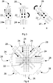
Figure 1 shows an arrangement of a typical proton computerised tomography system; -
Figure 2 is a diagrammatic illustration of the CT process; -
Figure 3 shows alternative approaches to the production of multiple samples during the CT process. -
Figure 4 is a diagrammatic illustration of the multiple samples during the CT process; -
Figure 5 is a comparison between FBP and BPF forms of CT; -
Figure 6 is a diagram showing a proton beam passing through an object to be imaged; -
Figure 7 shows a hypothetical path of a proton through position-sensitive detectors in an embodiment of the invention during imaging of a person; -
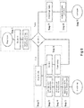
Figure 8 is a flow diagram that describes the steps carried out in a process embodying the invention; -
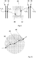
Figure 9 illustrates the points of interaction between a proton, position-sensitive detectors, and a person being imaged in an embodiment of the invention; -
Figure 10 illustrates a possible path of a proton and corresponding path models during imaging of a person in an embodiment of the invention; and -
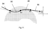
Figure 11 illustrates a path of a proton through an object, and the model of the path using a spline. -
Figure 1 shows the arrangement of a typical proton CT system. A beam ofprotons 10 passes through one or more position-sensitive detectors 12 and from there to impinge upon an object orpatient 14 to be imaged. If the energy of the protons is high enough, they will most likely pass through the object orpatient 14 and emerge from the far side of the patient with some residual energy, ER . The protons then pass through one or more position-sensitive detectors 16. The residual energy ER of the protons is then measured by an energy-sensitive detector 18. Data is collected from thedetectors computer system 20. The positions of individual protons as well as their residual energy, ER , are recorded for a unique relative position of the patient relative to the system. - Either the patient or the instrument is rotated by a small scan angle, typically 1° - 2°, about a central y-axis. The process is repeated over many scan angles.
- If p is the transmittance of the object, then p is given by the line integral:

Figure 2 , where anobject 22 is illuminated by abeam 24 to produce aprojection image 28. - In the two-dimensional case, the line L can be represented by the parameters r and θ, where θ measures the angle of the line from the vertical, and r measures the distance of the line from the origin of the (x, y) plane. The above formula is used to define a transform which maps a function f(x, y) to a function p(r, θ), where p(r, θ) is the line integral of f(x, y) over the line defined by rand θ. This transform is known as the Radon transform and denoted by R. The basic challenge of tomography is to reconstruct an image from its Radon transform. Fortunately, the Radon transform, when properly defined, has a well-defined inverse. In order to invert the transform, projection data spanning 180° is needed.
- The conventional approach to CT reconstruction is the Filtered Back Projection (FBP) method. The concept is explained in
Figure 3 (i) , where the forward projectedbeam 24 andattenuated beam 26 of theobject 22 is recorded as aprojection image 28.Figures 3 (ii) and (iii) show how other projection angles are obtained by either rotating the object with a fixed source and detector (Figure 3 (ii) ), or rotating the source and detector in tandem with a stationary object (Figure 3 (iii) ). - An arrangement that uses a finite number of (in this case, 8) sets of individual projection data from different scan angles then is as shown in
Figure 4 . Theindividual projection images 28 are shown projected back through the image to obtain an estimate of the internal structures of theoriginal object 22. The individual projections will interact constructively in regions that correspond to features in theoriginal object 22. - A problem that arises from the arrangement of
Figure 4 is that blurring and star-like artefacts occur in other parts of the reconstructed image. A high-pass or ramp filter is used to eliminate this blurring. The combination of filtering and back-projection provides this method with its customary name: "Filtered Back-Projection" (FBP). - There are numerous variations on the basic FBP approach. Since any practical input data will contain noise, and a ramp filter will accentuate this noise, some form of low-pass filtering is introduced to reduce the noise. There is a trade-off between the ramp filter characteristics and the filtering for noise suppression. The mean-squared optimal solution to this problem is to employ a Wiener filter.
- Hence, the essential steps in producing a CT image using FBP are:
- 1. Record with uniform sampling multiple individual projections through a 2-dimensional slice of an object to produce a 1-dimensional array.
- 2. Convolve this array of data with a 1-dimensional deblurring kernel (or the equivalent filtering in the spatial-frequency domain).
- 3. Back-project the convolved ray-projections through a 2-dimensional reconstruction matrix.
- 4. Repeat over many scan angles.
- An alternative to FBP is known in which the order of some operations is reversed - that is back-projection is performed before filtering - this can be termed as Back-Projection Filtered (BPF), an example being disclosed in S. Suzuki and S. Yamaguchi, Comparison between an image reconstruction method of filtering backprojection and the filtered backprojection method, Applied Optics 27(14):2867:2870 (1988). The two approaches are compared in
Figure 5 . The BPF approach has not been used in practice because of the need for a computationally more complex 2-dimensional filter rather than a 1-dimensional one, and, without the techniques presented by the present invention, has been shown to be quantitatively less accurate. - The embodiment of this invention implements a BPF using an analytic technique in to solve the reconstruction problem of going from the Radon transform of an object (that is the measurements) to the reconstructed object (that is the 2-dimensional image slice) only using each element of the data only once.
- For parallel beam tomography the projections can be expressed as the Radon transform of the object that is to be reconstructed. The Radon transform is defined as:


- Then:

- This approach for reconstructing the image is to take the inverse Radon transform of the projections. This involves two steps: the image is back-projected and then filtered with a 2-dimensional filter.
- The back-projection operator B is defined as:

- This operator represents the accumulation of the projections that pass through a point (x, y).
- Hence, the essential steps in producing a CT image using BPF in this embodiment are:
- 1. Record (with not necessarily uniform sampling) individual projections through a 2-dimensional slice of an object to produce a 1-dimensional array. It is possible to relax this strict condition, namely that proton paths stay solely with a 2-dimensional plane.
- 2. Back-project the projections through a 2-dimensional reconstruction matrix.
- 3. Convolve (or filter) this 2-dimensional data matrix with a 2-dimensional deblurring kernel.
- 4. Repeat over many scan angles. The scan angles need not be uniformly distributed.
- A formal treatment of the BPF approach embodying the invention will now be presented.
- Suppose a 2-dimensional slice of a body has some property described by the function, f(x, y), with a compact support, Ω f = {(x,y)∈ℜ2:x 2+y 2<R 2}. In the case of proton CT, the appropriate property is the proton relative stopping power. A line integral through the object, at an angle θ and position t (see
Figure 6 ) can be written as:
- This line integral is a ray projection through a slice of an object being imaged, and is related to the path length in a reference material, typically the water-equivalent path length (WEPL). The presence in a body of a patient with many different tissues, each with its own density, represents a challenge to image reconstruction. The concept of WEPL gets around this problem as the water equivalent approximation is based on the fact that the stopping powers of different materials are very similar to one another. The transform from the space (x, y) to (θ, t) is the Radon transform.
- The back-projection operation is defined as:

- This is equivalent to tracing back along the ray-projection path and depositing, at each location through which it passes, the value of the line integral. The resulting back-projection function, b(x, y), resembles a blurred representation of the density function, f(x, y). In fact, they are related through:

- This convolution relation can be expressed as a filtering operation in 2-dimensional Fourier space. Let the Fourier conjugate variables of (x, y) be (u, v) and ρ = ∥(u,v)∥. Then, it is possible to write:


- In a practical implementation, a discrete formulation for the back-projected image, b, needs to be used. The 2-dimensional matrix for b can be calculated from a set of acquired measurements in several ways. One possible scheme will now be described.
- Imagine that L projections are acquired over a set of different scan angles:


- This version relaxes the requirement for linear in-plane paths.
- The filtering operation of this embodiment will now be described.
- Two constraints must be imposed on the filtering operation: the sampling pitch and the finite size of the back-projection matrix. The first must be imposed on the filter in the frequency domain and then the second on the kernel in the spatial domain. The band-limit on spatial-frequencies is imposed by modifying the ramp filter representation of the kernel in frequency space:

- The relationship between the convolution kernel and filter involves a 2-dimensional Fourier transform (in contrast with the FBP procedure, which involves a 1-dimensional Fourier transform).
- The 2D convolution kernel, k(r), is now derived as:


- The finite size of the back-projection matrix and kernel must be considered in order to find the appropriate filter in the discrete Fourier space. The correct filter to use is a Discrete Fourier Transform (DFT) of the finite band-limited kernel derived above. This is:


- The process of finite matrix correction will now be described.
- The mathematical formulation given above described the BPF process and how to implement it. However, this formulation may not allow the reconstruction of quantitatively accurate images of proton stopping power. Although f(x, y) is clearly zero outside of the desired reconstruction region, the function b(x, y) is non-zero everywhere. In practice, the support for back-projection must be bounded:

- Previously, the only attempt to deal with this problem has been to make the size of the back-projection matrix (N × N), much larger than the desired image matrix (M × M) with, say, N = 4M. Such an approach is wasteful for computer memory and increases computation, as well as only asymptotically improving accuracy.
- The effect of missing data, due to a finite back-projection matrix, closely resembles a zero-frequency offset in the reconstructed stopping-power f(i, j). The effect of distant data on the reconstruction region will only manifest itself at low-spatial frequencies. A constant-shift offset correction can be arrived at in several ways.
- Consider the following: the distant values of the back-projection matrix (if far enough away from the central region) can be approximated as:


- To the central pixel, (N/2, N/2), this becomes:

- The first summation is the sum of all the pixel values in the reconstructed image slice(∈Ω f ). The second sum is a summation over all pixels outside the back-projection region(∉Ω b ).
- This is in principle an infinite sum, but can be evaluated inexpensively to a desired accuracy. This correction, C, calculated for one pixel, is then applied to all pixels in the image as a constant offset, that is:

- It should be noted that the above formulation for reconstruction assumes linear in-plane ray-projections (in this case, proton paths). As such, each slice of the 3D volume should factorize into a separate 2D problems with distinct data. This is the essence of classical tomography. In reality, due to beam angular dispersion and straggling, protons will not typically remain in the same axial plane as they progress through an object. However, both the angular dispersion and straggling of protons is typically small enough to be considered a perturbation. Typical root-mean-square figures for beam divergence before and after a patient might be 5 mrad and 50 mrad respectively (Bruzzi M, et al. 2007, Prototype Tracking Studies for Proton CT, IEEE Trans. Nucl. Sci. 54, 140-145), although these values would depend on the beam nozzle design, proton energy and size of patient. We therefore propose the following adaptation to non-linear out-of-plane paths. Firstly, the back-projection is performed as expressed in
equation 5 except that ray paths are back-projected along non-linear trajectories through the 3D volume and may pass through multiple axial slices. Secondly, the filtering operation, as described inequation 6 is performed slice by slice as if the protons had progressed linearly, parallel and in-plane. - The main elements of the proton CT system embodying the invention are shown in
Figure 7 . In this example, there are two sets of positionsensitive detectors sensitive detectors patient 22. The input vector, for an individual proton with initial energy E l , to the BPF algorithm consist of four sets of positional data obtained from the sets ofdetectors 30..36 {(x 1, y 2), ... , (x 4, y 4)} and the residual energy of the proton, ER , as recorded by an energy-sensitive detector 18 inFigure 1 . The path of the proton shown inFigure 7 is a diagrammatic example only. - With reference to
Figure 8 , the sequence of operations for the generation of a proton CT image in an embodiment of the invention will now be described. - In
Step 1, the number of rotations, N, is set and the Count initialised to zero. The values of the CT image matrix are also set to zero. - In
Step 2, data is acquired from the instrument (at the initial scan angle). This individual projection data consists of the recorded vector for each identified individual proton path and its residual energy, ER, that is:
- Proton energies are converted in
Step 3 into water-equivalent path lengths (WEPL), to preserve the uniform dimensionality of all parameters. There are several ways to achieve this conversion. In this example:
2 O (100) is the range in water of a 100 MeV proton, and El is the initial energy of the proton. - As a first option,

2 O is the stopping power for protons in water. - Or as a second option,

- It has been found that these three different approaches should provide answers that differ by less than 1%. The vector is now:

-
Step 4 is to estimate the path of each proton through thepatient 22. As illustrated inFigure 9 , this is done by projecting forward and backward from the respective (x, y) locations of theappropriate detectors 30..36 to determine the entry andexit voxels - Most Likely/Probable trajectory: for each of the two lateral directions, estimate the most likely displacement and direction vector for each proton at each z location along the beam axis (R. W. Schulte, et al, A maximum likelihood proton path formalism for application in proton computed tomography, Med. Phys. 35, 4849, 2008).
- Most Likely/Probable position: for each of the two lateral directions, estimate the most likely displacement for each proton at each z location along the beam axis (D. Wang, T. R. Mackie and W. A. Tome, On the use of a proton path probability map for proton computed tomography reconstruction, Med. Phys. 37, 4138, 2010).
- Approximate the path empirically using a smooth transition between the initial and final proton vectors e.g., cubic spline (D C Williams, The most likely path of an energetic charged particle through a uniform medium, Phys. Med. Biol. 49, 2899, 2004).
- Any of the above methods, or another, can be used to estimate the most likely path of an individual proton through reconstruction matrix. A smooth (non-linear)
path 46 or a piecewiselinear representation 48 of theactual path 50 can be used (illustrated inFigure 10 ) in respect to any of the above methods. - For example, an n-knot spline may be employed to model the
proton path 50, the inside the object. For each proton, n knot points K1, K2, K3 are equally spaced between phantom entry and exit points 54, 56. Inside the object, back-projection is assumed linear between any two knot points, as shown inFigure 11 . Outside the object, the protons are projected back from the surface with trajectories parallel to the beam axis (at an angle ϕ in the x-y plane). This prevents the back-projection rays "spreading-out" as they diverge from the object. Back-projecting away from the object into empty space along the actual entry and exit trajectories can result in a small quantitative error in the reconstructed stopping powers of up to 1%. - In
Step 5, the associated WEPLR values are back-projected into the image matrix. The relevant formulation is Eqn. (5). -
Steps 2 to 6 are repeated until Count = N. - In
step 7, the filtering operation given by Eqn. (8) is performed on the completed back-propagation matrix, b(x, y). - In
step 8, the Finite Matrix Correction factor, C, (Eqn. 10) is calculated and applied in accordance with Eqn. (11). - Finally, in
step 9, the proton CT image can be displayed. - The invention is as defined in the appended claims.
Claims (15)
- A method of 3-dimensional image reconstruction for hadron and ion beams in computerised tomography comprising:a. creating an image reconstruction matrix by:
from a plurality of scan angles surrounding an object (22) to be imaged:i. directing a plurality of particles (24) to traverse an object; andii. measuring a trajectory and energy of each particle before and after each particle has traversed the object;iii. calculating an equivalent path length (EPL) for each particle within the object;iv. calculating an entry position (40) at which each particle entered the object and an exit position (42) at which each particle exited the object; andv. adding the EPL to the entry and exit positions of each particle of the image reconstruction matrix or a subset of elements thereof;b. applying a spatially varying 2-dimensional filter function to the image reconstruction matrix to generate a filtered reconstruction matrix; andc. applying a correction factor to the filtered reconstruction matrix to at least partially correct for the finite extent of the matrix. - A method of image reconstruction according to claim 1 in which the particles are protons, other hadrons or ions.
- A method of image reconstruction according to claim 1 or claim 2 in which the EPL is awater-equivalent path length.
- A method of image reconstruction according to any preceding claim in which the trajectories of individual particles before traversal of the object are recorded by a multiplicity of position-sensitive detectors that are encountered by the particles before they encounter the object.
- A method of image reconstruction according to any preceding claim in which the trajectories of individual particles after traversal of the object are recorded by a multiplicity of position-sensitive detectors that are encountered by the particles after they have encountered the object.
- A method of image reconstruction according to any preceding claim in which each measured particle trajectory is traced back to create the image reconstruction matrix, and there is deposited at each location within this image reconstruction matrix corresponding values of the integral:

- A method of image reconstruction according to claim 6 in which creating the image reconstruction matrix is completed prior to any filtration being applied to its contents.
- A method of image reconstruction according to any preceding claim wherein the image reconstruction matrix is subject to a band-limited convolution kernel in which a sampling pitch of the matrix is imposed on the convolution kernel in the frequency domain.
- A method of image reconstruction according to claim 8 in which an additional smoothing filter is applied by sampling an appropriate function in the frequency domain and multiplying the convolution kernel.
- A method of image reconstruction according to claim 9 in which the additional smoothing filter is a Shepp-Logan or a Gaussian filter.
- A method of image reconstruction according to any preceding claim in which a back-projected image matrix is given by:

- A method according to claim 11 in which the 2-dimensional filter function has the form:

- A method according to any preceding claim in which the correction factor is

- A method of image reconstruction according to any preceding claim in which a further correction factor is applied to further reduce residual errors in the filtered reconstruction matrix to stop powers that arise from trajectories of particles exiting the object that are not parallel to a collimation axis of the incident particle beam.
- Computerised tomography apparatus comprising a source of particles, first detection means for detecting the position and energy of particles prior to their traversing an object, second detection means for detecting the position and energy of particles prior to their traversing an object, and analysing means configured to reconstruct an image of the object by analysis of output of the detection means using the method according to any preceding claim.
Applications Claiming Priority (2)
| Application Number | Priority Date | Filing Date | Title |
|---|---|---|---|
| GBGB1413729.3A GB201413729D0 (en) | 2014-08-01 | 2014-08-01 | Method and apparatus for proton computed tomography |
| PCT/GB2015/052208 WO2016016653A1 (en) | 2014-08-01 | 2015-07-30 | Method and apparatus for proton computerised tomography |
Publications (2)
| Publication Number | Publication Date |
|---|---|
| EP3174465A1 EP3174465A1 (en) | 2017-06-07 |
| EP3174465B1 true EP3174465B1 (en) | 2021-10-20 |
Family
ID=51587652
Family Applications (1)
| Application Number | Title | Priority Date | Filing Date |
|---|---|---|---|
| EP15747199.6A Active EP3174465B1 (en) | 2014-08-01 | 2015-07-30 | Method and apparatus for proton computerised tomography |
Country Status (4)
| Country | Link |
|---|---|
| US (1) | US10249063B2 (en) |
| EP (1) | EP3174465B1 (en) |
| GB (2) | GB201413729D0 (en) |
| WO (1) | WO2016016653A1 (en) |
Families Citing this family (11)
| Publication number | Priority date | Publication date | Assignee | Title |
|---|---|---|---|---|
| AU2017203109B2 (en) * | 2016-05-11 | 2018-12-06 | ProTom International Holding Corp. | Cancer treatment room fiducial marker apparatus and method of use thereof |
| US11141608B2 (en) | 2017-04-07 | 2021-10-12 | Massachusetts Institute Of Technology | Compact proton beam energy modulator |
| CN107497059A (en) * | 2017-07-12 | 2017-12-22 | 合肥中科离子医学技术装备有限公司 | One kind of proton CT accurate control methods |
| CN111836583B (en) * | 2017-12-28 | 2022-03-29 | 北伊利诺伊大学董事会 | Processing a pipeline for immediate particle image reconstruction |
| JP7273272B2 (en) * | 2018-05-28 | 2023-05-15 | 国立研究開発法人理化学研究所 | Acquisition method, acquisition device, and control program for tomographic image data by angular offset |
| US10690787B2 (en) * | 2018-07-16 | 2020-06-23 | Vieworks Co., Ltd. | Radiation imaging system |
| US11614552B2 (en) | 2019-04-18 | 2023-03-28 | Decision Sciences International Corporation | Charged particle scanners |
| WO2020246788A1 (en) * | 2019-06-05 | 2020-12-10 | 세종대학교산학협력단 | Scanning hologram-based automatic optical inspection apparatus and method |
| JP7264751B2 (en) * | 2019-07-08 | 2023-04-25 | 株式会社ニューフレアテクノロジー | Inspection device and inspection method |
| CN112569478B (en) * | 2019-09-29 | 2023-05-16 | 王宏凯 | Method and device for synchronously reading digital proton CT imaging |
| GB202311277D0 (en) * | 2023-07-21 | 2023-09-06 | Univ Of Lincoln | Aparatus for determing energy of hadron patricles |
Family Cites Families (11)
| Publication number | Priority date | Publication date | Assignee | Title |
|---|---|---|---|---|
| JPS6340381A (en) | 1986-08-06 | 1988-02-20 | Toshiba Corp | Radiation detector |
| FR2652655A1 (en) | 1989-10-04 | 1991-04-05 | Commissariat Energie Atomique | LARGE DIMENSIONAL MATRIX DEVICE FOR TAKING OR RETRIEVING IMAGES. |
| GB2359187A (en) | 2000-02-11 | 2001-08-15 | Kindbrisk Ltd | Device and method for two-dimensional detection of particles or electromagnetic radiation |
| DE10244176A1 (en) | 2002-09-23 | 2004-04-08 | Siemens Ag | X-ray detector for use in digital imaging, especially CT applications, has a multi-layer structure with interleaved support, fluorescing and photo-sensor layers to permit energy-resolved radiation detection |
| DE102009035231B4 (en) | 2009-07-29 | 2013-08-08 | Gsi Helmholtzzentrum Für Schwerionenforschung Gmbh | Phantom for the experimental in vitro validation of irradiations under the influence of motion taking into account the biologically effective dose |
| EP2534471A4 (en) | 2010-02-12 | 2015-03-18 | Univ Loma Linda Med | SYSTEMS AND METHODOLOGIES OF TOMODENSITOMETRY WITH PROTONS |
| JP2013527918A (en) | 2010-04-02 | 2013-07-04 | ボード オブ トラスティーズ オブ ノーザン イリノイ ユニバーシティー | High performance calculations for 3D proton computed tomography (HPC-PCT) |
| US20120292517A1 (en) | 2011-05-19 | 2012-11-22 | Washington University | Real-time imaging dosimeter systems and method |
| WO2013116709A1 (en) * | 2012-02-01 | 2013-08-08 | The Research Foundation of States University of New York | Computerized image reconstruction method and apparatus |
| JP5791546B2 (en) | 2012-02-29 | 2015-10-07 | 株式会社日立製作所 | Calibration method of radiation measuring apparatus and particle beam therapy apparatus |
| JP6452733B2 (en) * | 2014-06-16 | 2019-01-16 | ロマ リンダ ユニバーシティ | Radiography and computed tomography with high energy electron beam |
-
2014
- 2014-08-01 GB GBGB1413729.3A patent/GB201413729D0/en not_active Ceased
-
2015
- 2015-07-30 EP EP15747199.6A patent/EP3174465B1/en active Active
- 2015-07-30 US US15/500,371 patent/US10249063B2/en active Active
- 2015-07-30 WO PCT/GB2015/052208 patent/WO2016016653A1/en not_active Ceased
- 2015-07-30 GB GB1701973.8A patent/GB2543695B/en active Active
Also Published As
| Publication number | Publication date |
|---|---|
| US20170221230A1 (en) | 2017-08-03 |
| WO2016016653A1 (en) | 2016-02-04 |
| GB2543695B (en) | 2020-11-25 |
| EP3174465A1 (en) | 2017-06-07 |
| GB201413729D0 (en) | 2014-09-17 |
| GB2543695A (en) | 2017-04-26 |
| US10249063B2 (en) | 2019-04-02 |
| GB201701973D0 (en) | 2017-03-22 |
Similar Documents
| Publication | Publication Date | Title |
|---|---|---|
| US10249063B2 (en) | Method and apparatus for proton computerised tomography | |
| Zygmanski et al. | The measurement of proton stopping power using proton-cone-beam computed tomography | |
| US7418073B2 (en) | Computed tomography device and method with three-dimensional backprojection | |
| Thibault et al. | A three‐dimensional statistical approach to improved image quality for multislice helical CT | |
| Zhou et al. | A computer simulation platform for the optimization of a breast tomosynthesis system | |
| Rit et al. | Filtered backprojection proton CT reconstruction along most likely paths | |
| Yan et al. | Towards the clinical implementation of iterative low‐dose cone‐beam CT reconstruction in image‐guided radiation therapy: Cone/ring artifact correction and multiple GPU implementation | |
| Fahimian et al. | Radiation dose reduction in medical x‐ray CT via Fourier‐based iterative reconstruction | |
| CN103384498A (en) | Detection apparatus | |
| CN105326519B (en) | Method and device for formation, scattering component calculation and reconstruction of X-ray images | |
| Geva et al. | X-ray computed tomography through scatter | |
| Rambo Sølie et al. | Image quality of list-mode proton imaging without front trackers | |
| US8335358B2 (en) | Method and system for reconstructing a medical image of an object | |
| Krah et al. | Scattering proton CT | |
| Saha | Single photon emission computed tomography | |
| US7737972B2 (en) | Systems and methods for digital volumetric laminar tomography | |
| US9545231B2 (en) | Optimized aperture selection imaging computed tomography system and method | |
| Chen et al. | SparseCT: System concept and design of multislit collimators | |
| Lee et al. | Mutual information-based non-local total variation denoiser for low-dose cone-beam computed tomography | |
| Jacobson et al. | Abbreviated on-treatment CBCT using roughness penalized mono-energization of kV-MV data and a multi-layer MV imager | |
| CN117561545A (en) | Anchored kernel scattering estimate | |
| Lohvithee | Iterative reconstruction technique for cone-beam computed tomography with limited data | |
| CN111685786B (en) | X-ray CT device, image reconstruction device and image reconstruction method | |
| GLGGGGG et al. | This invention relates to a method and apparatus for 3-dimensional image reconstruction in computerised tomography. More specifically, it relates to computerised tomographic image reconstruction and typically in image reconstruction for applications in hadron (eg, proton) and ion beam therapy. | |
| Cai | Artefact Reduction Methods for Iterative Reconstruction in Full-fan Cone Beam CT Radiotherapy Applications |
Legal Events
| Date | Code | Title | Description |
|---|---|---|---|
| STAA | Information on the status of an ep patent application or granted ep patent |
Free format text: STATUS: THE INTERNATIONAL PUBLICATION HAS BEEN MADE |
|
| 17P | Request for examination filed |
Effective date: 20170207 |
|
| AK | Designated contracting states |
Kind code of ref document: A1 Designated state(s): AL AT BE BG CH CY CZ DE DK EE ES FI FR GB GR HR HU IE IS IT LI LT LU LV MC MK MT NL NO PL PT RO RS SE SI SK SM TR |
|
| AX | Request for extension of the european patent |
Extension state: BA ME |
|
| PUAI | Public reference made under article 153(3) epc to a published international application that has entered the european phase |
Free format text: ORIGINAL CODE: 0009012 |
|
| STAA | Information on the status of an ep patent application or granted ep patent |
Free format text: STATUS: REQUEST FOR EXAMINATION WAS MADE |
|
| DAV | Request for validation of the european patent (deleted) | ||
| DAX | Request for extension of the european patent (deleted) | ||
| GRAP | Despatch of communication of intention to grant a patent |
Free format text: ORIGINAL CODE: EPIDOSNIGR1 |
|
| STAA | Information on the status of an ep patent application or granted ep patent |
Free format text: STATUS: GRANT OF PATENT IS INTENDED |
|
| INTG | Intention to grant announced |
Effective date: 20210510 |
|
| GRAS | Grant fee paid |
Free format text: ORIGINAL CODE: EPIDOSNIGR3 |
|
| GRAA | (expected) grant |
Free format text: ORIGINAL CODE: 0009210 |
|
| STAA | Information on the status of an ep patent application or granted ep patent |
Free format text: STATUS: THE PATENT HAS BEEN GRANTED |
|
| AK | Designated contracting states |
Kind code of ref document: B1 Designated state(s): AL AT BE BG CH CY CZ DE DK EE ES FI FR GR HR HU IE IS IT LI LT LU LV MC MK MT NL NO PL PT RO RS SE SI SK SM TR |
|
| RBV | Designated contracting states (corrected) |
Designated state(s): AL AT BE BG CH CY CZ DE DK EE ES FI FR GR HR HU IE IS IT LI LT LU LV MC MK MT NL NO PL PT RO RS SE SI SK SM TR |
|
| REG | Reference to a national code |
Ref country code: CH Ref legal event code: EP |
|
| REG | Reference to a national code |
Ref country code: DE Ref legal event code: R096 Ref document number: 602015074268 Country of ref document: DE |
|
| REG | Reference to a national code |
Ref country code: IE Ref legal event code: FG4D |
|
| REG | Reference to a national code |
Ref country code: AT Ref legal event code: REF Ref document number: 1439248 Country of ref document: AT Kind code of ref document: T Effective date: 20211115 |
|
| REG | Reference to a national code |
Ref country code: LT Ref legal event code: MG9D |
|
| REG | Reference to a national code |
Ref country code: NL Ref legal event code: MP Effective date: 20211020 |
|
| REG | Reference to a national code |
Ref country code: AT Ref legal event code: MK05 Ref document number: 1439248 Country of ref document: AT Kind code of ref document: T Effective date: 20211020 |
|
| PG25 | Lapsed in a contracting state [announced via postgrant information from national office to epo] |
Ref country code: RS Free format text: LAPSE BECAUSE OF FAILURE TO SUBMIT A TRANSLATION OF THE DESCRIPTION OR TO PAY THE FEE WITHIN THE PRESCRIBED TIME-LIMIT Effective date: 20211020 Ref country code: LT Free format text: LAPSE BECAUSE OF FAILURE TO SUBMIT A TRANSLATION OF THE DESCRIPTION OR TO PAY THE FEE WITHIN THE PRESCRIBED TIME-LIMIT Effective date: 20211020 Ref country code: FI Free format text: LAPSE BECAUSE OF FAILURE TO SUBMIT A TRANSLATION OF THE DESCRIPTION OR TO PAY THE FEE WITHIN THE PRESCRIBED TIME-LIMIT Effective date: 20211020 Ref country code: BG Free format text: LAPSE BECAUSE OF FAILURE TO SUBMIT A TRANSLATION OF THE DESCRIPTION OR TO PAY THE FEE WITHIN THE PRESCRIBED TIME-LIMIT Effective date: 20220120 Ref country code: AT Free format text: LAPSE BECAUSE OF FAILURE TO SUBMIT A TRANSLATION OF THE DESCRIPTION OR TO PAY THE FEE WITHIN THE PRESCRIBED TIME-LIMIT Effective date: 20211020 |
|
| PG25 | Lapsed in a contracting state [announced via postgrant information from national office to epo] |
Ref country code: IS Free format text: LAPSE BECAUSE OF FAILURE TO SUBMIT A TRANSLATION OF THE DESCRIPTION OR TO PAY THE FEE WITHIN THE PRESCRIBED TIME-LIMIT Effective date: 20220220 Ref country code: SE Free format text: LAPSE BECAUSE OF FAILURE TO SUBMIT A TRANSLATION OF THE DESCRIPTION OR TO PAY THE FEE WITHIN THE PRESCRIBED TIME-LIMIT Effective date: 20211020 Ref country code: PT Free format text: LAPSE BECAUSE OF FAILURE TO SUBMIT A TRANSLATION OF THE DESCRIPTION OR TO PAY THE FEE WITHIN THE PRESCRIBED TIME-LIMIT Effective date: 20220221 Ref country code: PL Free format text: LAPSE BECAUSE OF FAILURE TO SUBMIT A TRANSLATION OF THE DESCRIPTION OR TO PAY THE FEE WITHIN THE PRESCRIBED TIME-LIMIT Effective date: 20211020 Ref country code: NO Free format text: LAPSE BECAUSE OF FAILURE TO SUBMIT A TRANSLATION OF THE DESCRIPTION OR TO PAY THE FEE WITHIN THE PRESCRIBED TIME-LIMIT Effective date: 20220120 Ref country code: NL Free format text: LAPSE BECAUSE OF FAILURE TO SUBMIT A TRANSLATION OF THE DESCRIPTION OR TO PAY THE FEE WITHIN THE PRESCRIBED TIME-LIMIT Effective date: 20211020 Ref country code: LV Free format text: LAPSE BECAUSE OF FAILURE TO SUBMIT A TRANSLATION OF THE DESCRIPTION OR TO PAY THE FEE WITHIN THE PRESCRIBED TIME-LIMIT Effective date: 20211020 Ref country code: HR Free format text: LAPSE BECAUSE OF FAILURE TO SUBMIT A TRANSLATION OF THE DESCRIPTION OR TO PAY THE FEE WITHIN THE PRESCRIBED TIME-LIMIT Effective date: 20211020 Ref country code: GR Free format text: LAPSE BECAUSE OF FAILURE TO SUBMIT A TRANSLATION OF THE DESCRIPTION OR TO PAY THE FEE WITHIN THE PRESCRIBED TIME-LIMIT Effective date: 20220121 Ref country code: ES Free format text: LAPSE BECAUSE OF FAILURE TO SUBMIT A TRANSLATION OF THE DESCRIPTION OR TO PAY THE FEE WITHIN THE PRESCRIBED TIME-LIMIT Effective date: 20211020 |
|
| REG | Reference to a national code |
Ref country code: DE Ref legal event code: R097 Ref document number: 602015074268 Country of ref document: DE |
|
| PG25 | Lapsed in a contracting state [announced via postgrant information from national office to epo] |
Ref country code: SM Free format text: LAPSE BECAUSE OF FAILURE TO SUBMIT A TRANSLATION OF THE DESCRIPTION OR TO PAY THE FEE WITHIN THE PRESCRIBED TIME-LIMIT Effective date: 20211020 Ref country code: SK Free format text: LAPSE BECAUSE OF FAILURE TO SUBMIT A TRANSLATION OF THE DESCRIPTION OR TO PAY THE FEE WITHIN THE PRESCRIBED TIME-LIMIT Effective date: 20211020 Ref country code: RO Free format text: LAPSE BECAUSE OF FAILURE TO SUBMIT A TRANSLATION OF THE DESCRIPTION OR TO PAY THE FEE WITHIN THE PRESCRIBED TIME-LIMIT Effective date: 20211020 Ref country code: EE Free format text: LAPSE BECAUSE OF FAILURE TO SUBMIT A TRANSLATION OF THE DESCRIPTION OR TO PAY THE FEE WITHIN THE PRESCRIBED TIME-LIMIT Effective date: 20211020 Ref country code: DK Free format text: LAPSE BECAUSE OF FAILURE TO SUBMIT A TRANSLATION OF THE DESCRIPTION OR TO PAY THE FEE WITHIN THE PRESCRIBED TIME-LIMIT Effective date: 20211020 Ref country code: CZ Free format text: LAPSE BECAUSE OF FAILURE TO SUBMIT A TRANSLATION OF THE DESCRIPTION OR TO PAY THE FEE WITHIN THE PRESCRIBED TIME-LIMIT Effective date: 20211020 |
|
| PLBE | No opposition filed within time limit |
Free format text: ORIGINAL CODE: 0009261 |
|
| STAA | Information on the status of an ep patent application or granted ep patent |
Free format text: STATUS: NO OPPOSITION FILED WITHIN TIME LIMIT |
|
| 26N | No opposition filed |
Effective date: 20220721 |
|
| PG25 | Lapsed in a contracting state [announced via postgrant information from national office to epo] |
Ref country code: AL Free format text: LAPSE BECAUSE OF FAILURE TO SUBMIT A TRANSLATION OF THE DESCRIPTION OR TO PAY THE FEE WITHIN THE PRESCRIBED TIME-LIMIT Effective date: 20211020 |
|
| PG25 | Lapsed in a contracting state [announced via postgrant information from national office to epo] |
Ref country code: SI Free format text: LAPSE BECAUSE OF FAILURE TO SUBMIT A TRANSLATION OF THE DESCRIPTION OR TO PAY THE FEE WITHIN THE PRESCRIBED TIME-LIMIT Effective date: 20211020 |
|
| PG25 | Lapsed in a contracting state [announced via postgrant information from national office to epo] |
Ref country code: MC Free format text: LAPSE BECAUSE OF FAILURE TO SUBMIT A TRANSLATION OF THE DESCRIPTION OR TO PAY THE FEE WITHIN THE PRESCRIBED TIME-LIMIT Effective date: 20211020 |
|
| REG | Reference to a national code |
Ref country code: CH Ref legal event code: PL |
|
| REG | Reference to a national code |
Ref country code: BE Ref legal event code: MM Effective date: 20220731 |
|
| PG25 | Lapsed in a contracting state [announced via postgrant information from national office to epo] |
Ref country code: LU Free format text: LAPSE BECAUSE OF NON-PAYMENT OF DUE FEES Effective date: 20220730 Ref country code: LI Free format text: LAPSE BECAUSE OF NON-PAYMENT OF DUE FEES Effective date: 20220731 Ref country code: CH Free format text: LAPSE BECAUSE OF NON-PAYMENT OF DUE FEES Effective date: 20220731 |
|
| PG25 | Lapsed in a contracting state [announced via postgrant information from national office to epo] |
Ref country code: IT Free format text: LAPSE BECAUSE OF FAILURE TO SUBMIT A TRANSLATION OF THE DESCRIPTION OR TO PAY THE FEE WITHIN THE PRESCRIBED TIME-LIMIT Effective date: 20211020 Ref country code: BE Free format text: LAPSE BECAUSE OF NON-PAYMENT OF DUE FEES Effective date: 20220731 |
|
| P01 | Opt-out of the competence of the unified patent court (upc) registered |
Effective date: 20230517 |
|
| PG25 | Lapsed in a contracting state [announced via postgrant information from national office to epo] |
Ref country code: IE Free format text: LAPSE BECAUSE OF NON-PAYMENT OF DUE FEES Effective date: 20220730 |
|
| PG25 | Lapsed in a contracting state [announced via postgrant information from national office to epo] |
Ref country code: HU Free format text: LAPSE BECAUSE OF FAILURE TO SUBMIT A TRANSLATION OF THE DESCRIPTION OR TO PAY THE FEE WITHIN THE PRESCRIBED TIME-LIMIT; INVALID AB INITIO Effective date: 20150730 |
|
| PG25 | Lapsed in a contracting state [announced via postgrant information from national office to epo] |
Ref country code: MK Free format text: LAPSE BECAUSE OF FAILURE TO SUBMIT A TRANSLATION OF THE DESCRIPTION OR TO PAY THE FEE WITHIN THE PRESCRIBED TIME-LIMIT Effective date: 20211020 Ref country code: CY Free format text: LAPSE BECAUSE OF FAILURE TO SUBMIT A TRANSLATION OF THE DESCRIPTION OR TO PAY THE FEE WITHIN THE PRESCRIBED TIME-LIMIT Effective date: 20211020 |
|
| PG25 | Lapsed in a contracting state [announced via postgrant information from national office to epo] |
Ref country code: TR Free format text: LAPSE BECAUSE OF FAILURE TO SUBMIT A TRANSLATION OF THE DESCRIPTION OR TO PAY THE FEE WITHIN THE PRESCRIBED TIME-LIMIT Effective date: 20211020 |
|
| PG25 | Lapsed in a contracting state [announced via postgrant information from national office to epo] |
Ref country code: MT Free format text: LAPSE BECAUSE OF FAILURE TO SUBMIT A TRANSLATION OF THE DESCRIPTION OR TO PAY THE FEE WITHIN THE PRESCRIBED TIME-LIMIT Effective date: 20211020 |
|
| PGFP | Annual fee paid to national office [announced via postgrant information from national office to epo] |
Ref country code: DE Payment date: 20250722 Year of fee payment: 11 |
|
| PGFP | Annual fee paid to national office [announced via postgrant information from national office to epo] |
Ref country code: FR Payment date: 20250725 Year of fee payment: 11 |