EP3174459B1 - Systeme zur optimierung von anti-tachykardien-stimulation (atp) - Google Patents
Systeme zur optimierung von anti-tachykardien-stimulation (atp) Download PDFInfo
- Publication number
- EP3174459B1 EP3174459B1 EP15826371.5A EP15826371A EP3174459B1 EP 3174459 B1 EP3174459 B1 EP 3174459B1 EP 15826371 A EP15826371 A EP 15826371A EP 3174459 B1 EP3174459 B1 EP 3174459B1
- Authority
- EP
- European Patent Office
- Prior art keywords
- pacing
- tachycardia
- electrodes
- atp
- time
- Prior art date
- Legal status (The legal status is an assumption and is not a legal conclusion. Google has not performed a legal analysis and makes no representation as to the accuracy of the status listed.)
- Active
Links
- 208000001871 Tachycardia Diseases 0.000 claims description 340
- 230000006794 tachycardia Effects 0.000 claims description 288
- 230000000638 stimulation Effects 0.000 claims description 130
- 230000037452 priming Effects 0.000 claims description 25
- 238000002560 therapeutic procedure Methods 0.000 claims description 25
- 230000000747 cardiac effect Effects 0.000 claims description 18
- 230000004044 response Effects 0.000 claims description 13
- 238000012544 monitoring process Methods 0.000 claims description 10
- 238000002513 implantation Methods 0.000 claims 1
- 238000004422 calculation algorithm Methods 0.000 description 43
- 206010049447 Tachyarrhythmia Diseases 0.000 description 30
- 238000004458 analytical method Methods 0.000 description 27
- 230000001133 acceleration Effects 0.000 description 25
- 206010036590 Premature baby Diseases 0.000 description 20
- 230000002763 arrhythmic effect Effects 0.000 description 19
- 230000000694 effects Effects 0.000 description 18
- 230000002107 myocardial effect Effects 0.000 description 18
- 238000000034 method Methods 0.000 description 17
- 238000005259 measurement Methods 0.000 description 15
- 230000028161 membrane depolarization Effects 0.000 description 14
- 206010047302 ventricular tachycardia Diseases 0.000 description 14
- 230000033764 rhythmic process Effects 0.000 description 13
- 230000035939 shock Effects 0.000 description 13
- 230000002336 repolarization Effects 0.000 description 12
- 206010003119 arrhythmia Diseases 0.000 description 10
- 210000004165 myocardium Anatomy 0.000 description 10
- 230000004927 fusion Effects 0.000 description 9
- 230000001746 atrial effect Effects 0.000 description 8
- 230000008859 change Effects 0.000 description 8
- 230000008878 coupling Effects 0.000 description 8
- 238000010168 coupling process Methods 0.000 description 8
- 238000005859 coupling reaction Methods 0.000 description 8
- 238000010586 diagram Methods 0.000 description 8
- 230000006793 arrhythmia Effects 0.000 description 7
- 230000001902 propagating effect Effects 0.000 description 7
- 210000005241 right ventricle Anatomy 0.000 description 7
- 230000002861 ventricular Effects 0.000 description 7
- 206010003668 atrial tachycardia Diseases 0.000 description 6
- 230000001965 increasing effect Effects 0.000 description 6
- 230000002085 persistent effect Effects 0.000 description 6
- 230000002028 premature Effects 0.000 description 6
- 210000005245 right atrium Anatomy 0.000 description 6
- 210000005240 left ventricle Anatomy 0.000 description 5
- 231100000241 scar Toxicity 0.000 description 5
- 230000004913 activation Effects 0.000 description 4
- 238000013194 cardioversion Methods 0.000 description 4
- 230000001447 compensatory effect Effects 0.000 description 4
- 230000002999 depolarising effect Effects 0.000 description 4
- 230000008569 process Effects 0.000 description 4
- 238000013459 approach Methods 0.000 description 3
- 206010061592 cardiac fibrillation Diseases 0.000 description 3
- 230000001934 delay Effects 0.000 description 3
- 230000001419 dependent effect Effects 0.000 description 3
- 230000037024 effective refractory period Effects 0.000 description 3
- 230000009177 electrical depolarization Effects 0.000 description 3
- 230000002600 fibrillogenic effect Effects 0.000 description 3
- 230000037361 pathway Effects 0.000 description 3
- 230000002035 prolonged effect Effects 0.000 description 3
- 208000003663 ventricular fibrillation Diseases 0.000 description 3
- 206010003658 Atrial Fibrillation Diseases 0.000 description 2
- 230000009471 action Effects 0.000 description 2
- 210000003748 coronary sinus Anatomy 0.000 description 2
- 230000003247 decreasing effect Effects 0.000 description 2
- 238000013461 design Methods 0.000 description 2
- 230000006870 function Effects 0.000 description 2
- 210000002837 heart atrium Anatomy 0.000 description 2
- 208000028867 ischemia Diseases 0.000 description 2
- 210000005246 left atrium Anatomy 0.000 description 2
- 239000012528 membrane Substances 0.000 description 2
- 238000012986 modification Methods 0.000 description 2
- 230000004048 modification Effects 0.000 description 2
- 208000010125 myocardial infarction Diseases 0.000 description 2
- 238000004904 shortening Methods 0.000 description 2
- 230000007704 transition Effects 0.000 description 2
- 210000003462 vein Anatomy 0.000 description 2
- 101150072179 ATP1 gene Proteins 0.000 description 1
- 101150093272 ATP9 gene Proteins 0.000 description 1
- 101100003366 Arabidopsis thaliana ATPA gene Proteins 0.000 description 1
- 208000033986 Device capturing issue Diseases 0.000 description 1
- 102100021649 Elongator complex protein 6 Human genes 0.000 description 1
- 101100065219 Homo sapiens ELP6 gene Proteins 0.000 description 1
- 101001071233 Homo sapiens PHD finger protein 1 Proteins 0.000 description 1
- 101000612397 Homo sapiens Prenylcysteine oxidase 1 Proteins 0.000 description 1
- 101100324954 Neurospora crassa (strain ATCC 24698 / 74-OR23-1A / CBS 708.71 / DSM 1257 / FGSC 987) oli gene Proteins 0.000 description 1
- 101150096101 OLI1 gene Proteins 0.000 description 1
- 102100036879 PHD finger protein 1 Human genes 0.000 description 1
- 241000387514 Waldo Species 0.000 description 1
- 230000036982 action potential Effects 0.000 description 1
- 101150105046 atpI gene Proteins 0.000 description 1
- 230000008901 benefit Effects 0.000 description 1
- 238000004364 calculation method Methods 0.000 description 1
- 230000001413 cellular effect Effects 0.000 description 1
- 230000000739 chaotic effect Effects 0.000 description 1
- 238000004891 communication Methods 0.000 description 1
- 239000004020 conductor Substances 0.000 description 1
- 230000006378 damage Effects 0.000 description 1
- 238000003066 decision tree Methods 0.000 description 1
- 230000003111 delayed effect Effects 0.000 description 1
- 230000003205 diastolic effect Effects 0.000 description 1
- 230000000763 evoking effect Effects 0.000 description 1
- 238000001428 flash vacuum thermolysis Methods 0.000 description 1
- 230000003993 interaction Effects 0.000 description 1
- 230000000302 ischemic effect Effects 0.000 description 1
- 230000007246 mechanism Effects 0.000 description 1
- 230000001191 orthodromic effect Effects 0.000 description 1
- 230000002688 persistence Effects 0.000 description 1
- 230000002265 prevention Effects 0.000 description 1
- 230000003449 preventive effect Effects 0.000 description 1
- 230000000750 progressive effect Effects 0.000 description 1
- 230000009467 reduction Effects 0.000 description 1
- 230000036279 refractory period Effects 0.000 description 1
- 238000005067 remediation Methods 0.000 description 1
- 238000004088 simulation Methods 0.000 description 1
- 230000004936 stimulating effect Effects 0.000 description 1
- 230000000153 supplemental effect Effects 0.000 description 1
- 206010042772 syncope Diseases 0.000 description 1
- 238000012360 testing method Methods 0.000 description 1
- 210000000591 tricuspid valve Anatomy 0.000 description 1
- 239000010926 waste battery Substances 0.000 description 1
Images


Classifications
-
- A—HUMAN NECESSITIES
- A61—MEDICAL OR VETERINARY SCIENCE; HYGIENE
- A61N—ELECTROTHERAPY; MAGNETOTHERAPY; RADIATION THERAPY; ULTRASOUND THERAPY
- A61N1/00—Electrotherapy; Circuits therefor
- A61N1/18—Applying electric currents by contact electrodes
- A61N1/32—Applying electric currents by contact electrodes alternating or intermittent currents
- A61N1/36—Applying electric currents by contact electrodes alternating or intermittent currents for stimulation
- A61N1/362—Heart stimulators
- A61N1/3621—Heart stimulators for treating or preventing abnormally high heart rate
- A61N1/3622—Heart stimulators for treating or preventing abnormally high heart rate comprising two or more electrodes co-operating with different heart regions
-
- A—HUMAN NECESSITIES
- A61—MEDICAL OR VETERINARY SCIENCE; HYGIENE
- A61N—ELECTROTHERAPY; MAGNETOTHERAPY; RADIATION THERAPY; ULTRASOUND THERAPY
- A61N1/00—Electrotherapy; Circuits therefor
- A61N1/18—Applying electric currents by contact electrodes
- A61N1/32—Applying electric currents by contact electrodes alternating or intermittent currents
- A61N1/36—Applying electric currents by contact electrodes alternating or intermittent currents for stimulation
- A61N1/362—Heart stimulators
- A61N1/365—Heart stimulators controlled by a physiological parameter, e.g. heart potential
- A61N1/36514—Heart stimulators controlled by a physiological parameter, e.g. heart potential controlled by a physiological quantity other than heart potential, e.g. blood pressure
-
- A—HUMAN NECESSITIES
- A61—MEDICAL OR VETERINARY SCIENCE; HYGIENE
- A61B—DIAGNOSIS; SURGERY; IDENTIFICATION
- A61B5/00—Measuring for diagnostic purposes; Identification of persons
- A61B5/24—Detecting, measuring or recording bioelectric or biomagnetic signals of the body or parts thereof
- A61B5/316—Modalities, i.e. specific diagnostic methods
- A61B5/318—Heart-related electrical modalities, e.g. electrocardiography [ECG]
- A61B5/346—Analysis of electrocardiograms
- A61B5/349—Detecting specific parameters of the electrocardiograph cycle
- A61B5/363—Detecting tachycardia or bradycardia
-
- A—HUMAN NECESSITIES
- A61—MEDICAL OR VETERINARY SCIENCE; HYGIENE
- A61B—DIAGNOSIS; SURGERY; IDENTIFICATION
- A61B5/00—Measuring for diagnostic purposes; Identification of persons
- A61B5/72—Signal processing specially adapted for physiological signals or for diagnostic purposes
- A61B5/7271—Specific aspects of physiological measurement analysis
- A61B5/7282—Event detection, e.g. detecting unique waveforms indicative of a medical condition
Definitions
- This invention is in the field of devices to diagnose and treat cardiac arrhythmias.
- tachycardias Abnormally fast heart rates are called tachycardias.
- tachycardia When the tachycardia occurs in the top chambers of the heart (the atria), this is termed atrial tachycardia.
- atrial tachycardia When it occurs in the bottom chambers (the ventricles), this is termed ventricular tachycardia.
- ventricular tachycardia Abnormally fast heart rates.
- depolarizing cells result in a self-propagating mechanism, whereby depolarizing wavefronts travel through myocardial tissue.
- a propagating wavefront may travel around non-conducting tissue.
- the resulting wavefront can then get caught in a perpetual loop where the electrical signal in the myocardial tissue circles around a fixed point or central scar.
- the action potentials will continually propagate around the non-conducting tissue (such as a prior myocardial infarction) at a rate considerably faster than the heart's intrinsic rate.
- the reentrant circuit can be thought of as a conduction wavefront propagating along a tissue mass of approximately circular geometry.
- ATP anti-tachycardia pacing
- the rate at which myocardial tissue can allow a propagating wavefront to conduct through it has a limit. Once depolarized, the tissue must repolarize in order to conduct another propagating wavefront. If a wavefront approaches myocardial tissue which has not repolarized the tissue cannot conduct the wavefront and the electrical signal will terminate. Tissue that has not yet repolarized and cannot conduct an electrical signal is termed refractory.
- a pacing stimulus is provided at a time and location such that the resulting wave propagation fails to conduct down the pathway of the reentrant circuit.
- the paced stimulation wavefront proceeds toward the arrhythmic circuit. This wavefront can approach both sides of the reentrant circuit (see figure 4 for clarity); such that the wavefront will collide with the wavefront leaving the reentrant circuit (termed the 'exit' site). With more pacing, the paced wavefront will reach the native tachycardia prior to the reentrant wavefront; resulting in an earlier depolarization of the reentrant circuit.
- the probability of anti-tachycardia pacing (ATP) succeeding in terminating a tachycardia is related to the ability of the pacing stimulation wavefront to arrive at the location of the reentrant circuit in such a manner that the propagating signal in the reentrant circuit is modified, is unable to perpetuate the propagating signal, and the tachycardia is terminated.
- pacing modalities and algorithms have been created for the termination of tachycardia. These algorithms have been created for both atrial and ventricular tachycardias. These algorithms are programmed into implanted devices such as a pacemaker or implantable cardioverter-defibrillators (ICDs). These devices may deliver a high powered electrical shock which attempts to reset all cells involved in the reentrant tachycardia in order to terminate the tachycardia. These shocks are often painful and can cause harm to myocardial cells. Alternatively, the devices may deliver anti-tachycardia pacing (ATP), whereby paced wavefronts reach critical aspects of the reentrant circuit in such a manner that the tachycardia terminates. ATP is usually painless and therefore has advantages over high-powered cardioversions.
- ATP anti-tachycardia pacing
- US 6,766,196 describes a method and device for performing anti-tachycardia pacing (ATP) to convert a ventricular tachycardia (VT) to normal sinus rhythm.
- Pacing/sensing electrodes are implanted in or on the left and right ventricles of a patient's heart. After a VT is detected a determination is made based on the shape of the electrogram signal of the VT.
- One of a plurality of time offsets for pacing pulses of the left and right ventricles is selected based on the signal shape and ATP is performed by pacing both the left and right ventricles with the time offset between pulses in the respective ventricles.
- US 2007/0191900 describes a method and device for delivering anti-tachycardia pacing (ATP) therapy that includes an electrode to sense cardiac signals and to deliver the therapy, sensing circuitry, electrically coupled to the electrode, to detect the tachycardia event in response to the sensed cardiac signals, and a processor to control delivery of the therapy.
- ATP anti-tachycardia pacing
- the processor determines a cause of the delivered first plurality of pacing pulses failing to terminate the tachycardia event as a result of one of a failure to capture the tachycardia event, a failure to complete peelback, and a failure to entrain a reentrant circuit associated with the tachycardia event, and adjusts delivery of a second plurality of pacing pulses subsequent to the delivery of the first plurality of pacing pulses in response to the determined cause.
- ATP is not always successful at terminating the tachycardia. In this circumstance, the ATP is repeated at the same or different pacing algorithm in attempts to terminate the arrhythmic into a normal sinus rhythm. If ATP is unsuccessful, the patient may require high voltage cardioversion. ATP is unsuccessful in approximately 10-40% of ATP attempts. In addition, ATP sometimes accelerates the rhythm to a faster rate or may degenerate the rhythm into ventricular fibrillation, which is a chaotic rhythm that is not capable of sustaining life. Furthermore, the longer the patient is in ventricular tachycardia, the more likely the patient is to pass out (syncope) which is dangerous.
- ATP often functions by entraining the tachycardia.
- Entraining is a process whereby paced beats (by a pacemaker lead, for example) accelerates the tachycardia.
- One or more stimulations are provided at a rate slightly faster than the tachycardia, such that the paced wavefronts enter and accelerate the tachycardia.
- the first paced stimulation that advances the reentrant tachycardia resets the tachycardia.
- the next pacing stimulation typically advances the tachycardia to the paced cycle length. Since myocardial tissue properties often change in response to shorter cycle lengths, several resetting stimulations may be needed to completely advance the tachycardia to the pacing cycle length.
- Each paced beat then 'resets' the tachycardia to the faster rate, termed entrainment.
- the faster rate is too fast for the arrhythmic circuit, such that the tissue has not had enough time to repolarize. In this case, the wavefront terminates, and the patient returns to sinus rhythm.
- Entrainment involves identifying a specific response of a reentrant arrhythmia to external pacing, including: (1) beat to beat interaction between the paced and tachycardia wavefront; (2) activation of all the tissue in the chamber where the circuit is located; and (3) persistence of the tachycardia after pacing, if the tachyarrhythmia does not self-terminate. If the self-sustaining tachyarrhythmia of the heart is thought of as an electrical circuit running in a circle, one can "entrain" that circuit by pacing slightly faster than the circuit was running on its own.
- the post-pacing interval has long been used as an indication of the proximity of the pacing site to the reentry circuit. (Stevenson, Khan et al. 1993) (Waldo 1997).
- the ATP algorithm depends on the type (atrial versus ventricular) and rate of the tachycardia. For example, most device makers make a distinction between ventricular tachycardia (VT), fast ventricular tachycardia (FVT), and ventricular fibrillation (VF) based on the rate of the tachycardia.
- the tachycardia rate can be described in terms of beats per minute (BPM) or can be thought of as the time between heart beats (termed the RR interval). This time is also termed the tachycardia cycle length (TCL), and is often given in milliseconds. 60,000 divided by the heart rate provides the cycle length in milliseconds (ms). For example, a tachycardia of 200 BPM has a tachycardia cycle length of 300ms.
- ATP can be a pacing train of a certain cycle length (burst pacing) or can shorten the cycle length with each additional paced beat (often termed ramp pacing).
- Ramp therapy consists of a decremental drive of a programmable number of pulses, starting at a rate proportional to the current tachycardial cycle length (TCL).
- the first therapy in the FVT zone was 2 ATP sequences (8-pulse burst pacing train at 88% of the FVT cycle length). If the first ATP sequence was unsuccessful, the second sequence was delivered at 88% of the FVT cycle length minus 10 ms. ATP therapies were delivered at maximum voltage and pulse duration. Programming of subsequent FVT therapies was left to the investigators' discretion and usually involved ICD shocks.
- Implantable cardioverter/defibrillators were programmed to deliver 10 ATP attempts for FVT cycle lengths (CLs) of 250-300 ms (200-240 BPM) before shock delivery (5 bursts, then 5 ramps; 8-10 extrastimuli at 81-88% FVT CL; minimal pacing CL 180 ms).
- CLs FVT cycle lengths
- over 20% of the patient experienced ATP that required more than two episodes of ATP.
- the most advanced pacemakers feature atrial preventive pacing and atrial anti-tachycardia pacing (DDDRP), which may reduce atrial fibrillation occurrence and duration.
- the device automatically delivers ATP therapies when an episode is classified as atrial tachycardia and lasts longer than a programmable 'time to first therapy' (often 1 min).
- ramp is programmed in order to deliver three series of ten sequences each, so that each patient could receive up to thirty termination attempts.
- Each series begins with a train of ten pulses.
- the first pulse of each of the three series is delivered at 91, 84, and 81% of the underlying atrial tachycardia cycle length (ATCL), respectively.
- subsequent pulses were delivered with a decrement in pacing coupling interval of 10ms each. If a previous train fails to terminate AT, an additional stimulus is added to the next train.
- Burst+ therapy uses a drive of a programmable number of atrial pulses, the rate of which is proportional to the current ATCL, followed by up to two extrastimuli.
- Burst+ is programmed in order to deliver three series of ten sequences each; each sequence is made up of fifteen pulses followed by two extrastimuli.
- each patient can receive up to thirty termination attempts.
- the first scan of each series is released at 84% of the underlying ATCL.
- the first extrastimulus is delivered at 81% of the underlying ATCL; the second extrastimulus was delivered with an interval reduced by 20ms. In the event of failure, the ATP train coupling interval was decreased by 10ms for each subsequent scan.
- the minimal pacing interval was 150 ms, so that pulses programmed at a shorter pacing interval than the MPI were delivered at the MPI value.
- Atrial ATP was recently found to significantly reduce the progression of atrial tachycardia to permanent atrial fibrillation (61% relative risk reduction) over a 2 year follow-up.
- the present invention is directed to systems for prevention and/or remediation of cardiac arrhythmias, e.g. optimizing anti-tachycardia pacing (ATP) algorithms. More particularly, the present invention is directed to implantable devices that measure and treat cardiac arrhythmias. By monitoring the ATP attempt from additional electrodes, far-field morphology analyses, and/or measuring the return interval from a failed ATP attempt; the present application describes examples where the device estimates the timing of entrainment, the amount of delay within the reentrant tachycardia, and/or tachycardia termination/acceleration. These variables and occurrences can be used to optimize the first and/or subsequent ATP attempts. Furthermore, other exemplary embodiments describe methods to integrate electrical restitution properties into the design of ATP pacing algorithms to facilitate tachycardia termination.
- ATP anti-tachycardia pacing
- the device may identify reentrant tachycardias based on timing intervals, far-field morphology, and/or the time differences between multiple electrodes.
- the device may also monitor for arrhythmia entrainment and/or termination during deliver of ATP to optimize the current and future ATP algorithms.
- other embodiments herein may estimate and record certain aspects of the ATP attempt, such as the total premature pacing time required to entrain the tachycardia ("the Time to Entrainment"), conduction delay occurring within the tachycardia circuit (the “Time Delay”), changes in the tachycardia (such as tachycardia acceleration), tachycardia termination, and the prior successfulness and failures of certain ATP strategies.
- the device can use these measurements and occurrences to improve the probability of tachycardia termination by leveraging electrical restitution properties of myocardial tissue.
- Examples are described herein of organizing the initial pacing intervals to minimize partial tachycardia acceleration as well as the strategy of delivering "priming" pacing pulses, or pulses delivered at longer intervals than typically seen in anti-tachycardia pacing attempts; in efforts to slow repolarization rates in critical aspects of the arrhythmic circuit. These methods will therefore improve the successfulness of ATP attempts, decrease the time the patient spends in dangerous tachyarrhythmias, and reduce the need for ICD shocks. Therefore, the following concepts are advantageous to programming and designing device ATP capabilities and algorithms.
- examples disclosed herein are directed to treating tachyarrhythmias, such as ventricular tachycardia, by employing at least one electrode to deliver electrical stimulation to a patient's heart in a manner designed to terminate a tachyarrhythmia episode.
- tachyarrhythmias such as ventricular tachycardia
- Overdrive pacing is typically performed at a rate faster than the native tachycardia; therefore the paced cycle length is usually shorter than the tachycardia cycle length (PCL ⁇ TCL).
- PCL ⁇ TCL tachycardia cycle length
- Each paced stimulation 'gains' on the native tachycardia by the amount of pacing prematurity, or the difference between the tachycardia cycle length and overdrive pacing cycle length (TCL-PCL).
- Overdrive pacing continues to 'gain' on the native tachycardia until the paced wave front reaches and then accelerates the native tachycardia. Once overdrive pacing reaches the arrhythmic circuit, additional pacing stimulations continuously resets the native tachycardia to the PCL (entrainment).
- the total amount of time overdrive pacing "gains" on the native tachycardia before pacing begins to accelerate/reset the native tachycardia can be calculated in equation 1 based on the number of pacing simulations required to accelerate the tachycardia (n), the difference between the tachycardia cycle length and the paced cycle length (TCL-PCL) [which can be variable], minus the amount of tachycardia acceleration.
- Time Gained ⁇ 0 n TCL ⁇ PCL ⁇ tachycardia advancement
- a distant electrode may be able to monitor the TCL during overdrive pacing and estimate the timing of tachycardia entrainment and conduction delay within the reentrant tachycardia.
- the total amount of time overdrive pacing needs to gain on the native tachycardia in order to entrain the tachycardia can be approximated by the post-pacing interval minus the tachycardia cycle length (PPI-TCL).
- the postpacing interval (PPI) or the return interval (RI) is the return interval that occurs after an entrainment maneuver or a failed ATP attempt. This time is the time required for the paced signal to travel from the pacing location, around the reentrant circuit, and then back to the pacing electrode.
- the total amount of time overdrive pacing must overcome in order to attain entrainment can be mathematically determined.
- the return cycle of the compensatory pause is equal to the TCL plus the amount of pacing prematurity (TCL-PCL). With additional pacing stimulations, the return cycle of the compensatory pause continues to prolong with each paced stimulation ( equation 2 ). Once pacing reaches the arrhythmic circuit, the paced wavefront accelerates the native tachycardia, and the return cycle is shorter than would, be predicted from a compensatory pause. Assuming minimal changes in conduction velocity, the return cycle of the first entrained beat, as well as all additional pacing stimulations, will be fixed at the PPI.
- the uncorrected PPI can be determined by adding the tachycardia cycle length to the total amount of pacing prematurity, minus the amount of tachycardia advancement (equation 3).
- PPI TCL + n ⁇ TCL ⁇ PCL ⁇ tachycardia advacement
- the following pacing stimulation will entrain the tachycardia to the PCL.
- all electrodes within the pacing chamber (whether the atria or ventricles) will accelerate to the paced cycle length. Therefore, by having an electrode in the myocardial tissue receiving the depolarized wavefront exiting the reentrant tachycardia, the timing of entrainment can be estimated. Furthermore, the amount of delay within the reentrant circuit can be estimated with this electrode. In some circumstances, the time to entrainment can be difficult to estimate, even with optimal locations of the distal electrodes. This error can occur because the first stimulation accelerating the native tachycardia can introduce significant conduction delay, which may not be fully appreciated.
- the entrainment time for electrode B can be determined by equation 6 , where the time differences between the electrodes during entrainment at more than one location are utilized to estimate the entrainment time for electrode B.
- This equation assumes the overdrive pacing cycle length is similar for all entrainments.
- Entrain Time B Stim A ⁇ B + Stim B ⁇ A ⁇ PPI A ⁇ A
- the PPI-TCL is equal to the sum of the pacing prematurity until entrainment is obtained. Furthermore, the PPI-TCL is also equal to the time difference between the pacing electrode and a distal electrode between an entrained tachycardia and the reentrant tachycardia.
- a similar method, which relies upon the post entrained stimulation (as opposed to the baseline interval) has been described by Stevenson as the N+1 rule (Friedman, 2001).
- the amount of conduction delay can be estimated by the time difference between the first entrained stimulation and a stable conduction time with persistent pacing. The prolongation in this time from persistent pacing or shorter cycle lengths can be used to estimate the conduction delay within the reentrant circuit.
- far-field waveform morphology analyses can help determine when a tachycardia has been entrained and the amount of conduction delay within the reentrant circuit. This is because during entrainment, the far-field morphology is the fusion between the paced morphology and the reentrant morphology. The differences between the far-field paced morphology, baseline reentrant morphology, and the fusion morphology can be used to estimate the timing of entrainment and the amount of delay within the reentrant circuit. With persistent pacing at a cycle length shorter than the tachycardia cycle length, there is progressive fusion between the paced waveform and the tachycardia waveform.
- the entrainment time can be estimated. Furthermore, if the morphology significantly changes to match the baseline paced morphology; this provides evidence of tachycardia termination. Furthermore, by comparing the Entrainment time and fusion morphology over a series of pacing stimulation, the Time delay occurring within the tachycardia circuit can be estimated. These variables can be combined to determine the optimal initial pacing algorithm to minimize partial acceleration; in addition, these variables can be used to optimize the "priming" pulse, to facilitate tachycardia termination.
- the difference in time between the electrodes during the reentrant tachycardia can be used to estimate the time to entrainment. This is because the entrainment pathway may involve certain aspects of the tachycardia reentrant tachycardia. Since the conduction times between the electrodes can be measured prior to any tachycardia, the prematurity required to reset/entrain the tachycardia can be estimated. Therefore, in some circumstances (such as a very fast tachycardia), only one ATP attempt can be delivered prior to proceeding with cardiac defibrillation. In these circumstances, the time differences between electrodes can be combined with the conduction times when not in tachycardia can be used to deliver a single ATP attempt with an increased probability of minimizing tachycardia partial acceleration.
- the pacing electrode(s) when entraining a tachycardia, the pacing electrode(s) may be far from the entrain site into areas of slow conduction. When the entrance site is far away from the pacing location(s), overdrive pacing may advance much of the myocardium prior to advancing the entrance site. In these circumstances, the sensing electrodes and far-field pacing morphology may not be helpful in identifying conduction slowing within critical aspects of the reentrant circuit. Therefore, in yet another embodiment, the pacing electrode is selected using the time intervals between electrodes during the tachycardia. In general, the latest occurring electrode can be chosen.
- baseline conduction times and far-field morphology can be measured and compared against tachycardia time intervals and far-field morphology to determine the optimal pacing electrode from which to pace.
- ATP pulses can be delivered from both electrodes, and based on the far-field morphology (or additional non-pacing electrode) the electrode closest to the entrance site can be used for subsequent pacing stimulations.
- the timing of tachycardia entrainment and the amount of delay within the reentrant circuit can be estimated by 1) measuring post-pacing interval to failed ATP attempts 2) by analyzing the timing of intracardiac signals from a distal electrode within the chambers of interest, and/or 3) by far-field morphology analyses. Knowing this can be used to optimize the first and subsequent ATP attempts.
- the timing of tachycardia acceleration can be determined at any overdrive pacing cycle length.
- Our studies have revealed that after adjusting for decremental conduction, the timing of entrainment can be estimated within a few milliseconds. Therefore, the entrainment time from the first or prior failed ATP attempt can be used to optimize subsequent ATP attempts.
- the number of pacing stimulations can be limited in order to minimize the possibility of tachycardia acceleration or fibrillation.
- Additional pacing stimulations delay termination to the tachycardia, waste battery life, and significantly increase the risk of developing faster tachycardias and/or disintegration into fibrillation.
- electrical restitution properties change with overdrive pacing.
- the first pacing stimulation that reaches the arrhythmic circuit will accelerate the native tachycardia by some fraction of time between the TCL and the PCL; which is dependent upon many factors, including the distance between the pacing stimulation location and the reentrant tachycardia. If the first stimulation that reaches the arrhythmic circuit only partially accelerates the tachycardia to the PCL, the electrical restitution curves dictate the critical aspects of the reentrant circuit are more likely to tolerate the tachycardia when accelerated to the PCL. The relationship between depolarization rates and repolarization times is known as the electrical restitution curve.
- partial acceleration may prepare the tachycardia to tolerate the ATP at faster overdrive pacing cycle lengths.
- the ATP algorithm can be set up such that the first pacing stimulation to accelerate the native tachycardia completely accelerates the tachycardia to the PCL (or desired interval). Delivering premature stimulations that only partially accelerate the native circuit may accelerate repolarization rates and make the tachycardia more difficult to pace-terminate.
- an ATP attempt can deliver stimulations and measure the response.
- the device can deliver one or more stimulation(s) at a longer cycle length (for example, based upon the tachycardia cycle length) followed by a paced cycle length at an even shorter cycle length. Again, the tachycardia can be monitored for changes or termination. Therefore, the device can continue pacing and adjusting the pulsing cycle length in order to facilitate tachycardia termination without stopping the ATP attempt. By delivering pulses near the tachycardia cycle length, electrical restitution properties are leveraged to optimize tachycardia termination.
- the first stimulated wavefront to accelerate the tachycardia accelerates the native tachycardia by less than the difference between the tachycardia cycle length (TCL) and the overdrive pacing cycle length (PCL); the partially accelerated tachycardia will prepare the tachycardia to tolerate the overdrive pacing cycle length (PCL). Therefore, by determining the amount of time required in order to accelerate a tachycardia; the algorithm of overdrive pacing can be optimized to increase the successfulness of the ATP attempt.
- conduction velocities may slow at shorter pacing cycle lengths and therefore serve to 'protect' critical aspects of the reentrant circuit; repolarization rates tend to be more sensitive than conduction velocities in response to shortening diastolic intervals. That is to say, premature stimulations rarely prolong conduction times across the critical isthmus, even in tachycardias with very circuitous and delayed conduction times. Therefore, minimizing "partial acceleration" will facilitate tachycardia termination, even with significant conduction velocity slowing associated with the shorter pacing cycle length.
- the anti-tachycardia pacing algorithm can be optimized. This can be used to determine how many paced beats to initiate and the pacing interval(s) to use. The pacing intervals can be adjusted such that the entrance site is activated at the same time the native arrhythmia meets the entrance site. The following stimulated wavefront can be delivered to excite the arrhythmia circuit at a shorter pacing interval.
- this tissue can be optimized by the prior pacing intervals to accept the shortest possible pacing interval.
- This interval can be mathematically calculated and then optimized based on the time required to entrain the tachycardia.
- This pacing interval after the initial entraining stimulations can then be gradually shortened until the tachycardia is terminated.
- Various stimulation morphologies and algorithms can also be used to optimize local capture.
- the timing of tachycardia entrainment can be used to optimize the initial overdrive pacing algorithm. Additionally, it is advantageous to improve the first ATP attempt.
- the depolarized wavefronts from the pacing electrode are able to reach the reentrant circuit.
- a distal electrode and/or wavefront morphology analyses can often determine when entrainment has been obtained and also if the tachycardia has been terminated. This concept is discussed extensively in the supplemental figures.
- the pacing electrode can deliver a single or multiple stimulations at the original tachycardia cycle length. If this occurs, the pacing wavefront will reach the reentrant circuit at approximately the same time as the native wavefront traveling in the reentrant circuit.
- the tachycardia cycle length determines the repolarization rates within the tachycardia circuit. Therefore, an ATP attempt can deliver stimulations at a slower cycle length (such as the original tachycardia cycle length) in order to delay the rate of repolarization. For example, an ATP attempt may deliver eight stimulations at PCL1.
- Far-field morphology and a distal electrode identify the tachycardia has been entrained.
- the ATP algorithm can now deliver one or several pacing stimulations at the original tachycardia cycle length. This slower rate will delay the rate of tissue repolarization; however, pacing maintains access the pacing electrode has with the reentrant tachycardia.
- the ATP algorithm can then deliver a single or several stimulations at a shorter cycle length that rapidly and completely accelerates the tachycardia.
- Far-field morphology and the distal electrode can identify if the tachycardia has been terminated.
- the device can deliver a single or several stimulations at the tachycardia cycle length, followed by a single or several stimulations at an even shorter cycle length than the previous attempt. This pattern can be repeated at shorter and shorter cycle lengths until the tachycardia is terminated. In this manner, only a single ATP attempt is required to terminate the tachycardia and also improves the ability to terminate the tachycardia at any given paced cycle length.
- the post-pacing interval, far-field morphology analyses, and timing of signals from a distal electrode in response to overdrive pacing can all be used alone or in combination with other methods to estimate the amount of conduction delay within the tachycardia circuit.
- This conduction delay can be added to the 'priming' stimulation, such that a single pacing stimulation at the tachycardia cycle length plus the amount of tachycardia delay is delivered after entrainment has been obtained.
- the priming stimulation slows the repolarization time within the tachycardia circuit while maintaining access for the pacing location to reach the reentrant circuit.
- an additional pacing stimulation with a shorter pacing cycle length can then be delivered with a greater probability of tachycardia termination.
- tachycardia termination, entrainment, and conduction delay within the reentrant circuit can be estimated in order to deliver additional 'priming' stimulations followed by a shorter stimulation.
- the ATP algorithm is reactive in the sense that responses from overdrive pacing are utilized in order to optimize the ATP attempt. This process can also be repeated to facilitate tachycardia termination. Sensing the timing of entrainment or tachycardia termination can sometimes be difficult when the sensed time falls near the stimulation time.
- the various electrodes can increase the probability the appropriate window for tachycardia assessment (both entrainment and termination) will be present.
- recording the success prior ATP attempts have had in terminating the defined tachycardia repeating of a successful pacing algorithm can be performed; or, if unsuccessful, the paced cycle lengths can be shortened.
- a distal electrode and far-field morphology may or may not identify entrainment and/or tachycardia termination. These abilities are dependent on a number of details specific to the tachycardia including spatial relationships between electrodes and the native tachycardia and conduction properties within the myocardium. Fortunately, bi-ventricular pacing systems usually incorporate two electrodes, which are distant from each other. Having two electrodes distant to each other across the myocardium increases the probability that these electrodes will be able to determine the timing of tachycardia entrainment, tachycardia termination, and the amount of time delay within the reentrant tachycardia.
- One exemplary embodiment describes far-field morphologies, tachycardia rates, and timing differences between electrodes to identify various reentrant tachycardias a patient may have. By accurately identifying the varying reentrant tachycardias, prior ATP failures and attempts can used to optimize subsequent ATP attempts.
- a second distal electrode within the heart can be used to monitor the ATP attempt. Time changes in the tachycardia cycle length during pacing are used to adjust the next stimulated pacing cycle length.
- the ATP algorithm can deliver one or more stimulations close to the baseline tachycardia cycle length plus some percentage of the measured time delay within the circuit (or a function related to one or both measurements), followed by one or more stimulations at a shorter pacing cycle length.
- the long pacing cycle lengths serve to 'prime' the reentrant tachycardia to prolong repolarization times in order to facilitate tachycardia termination.
- the shorter cycle length may cause conduction delay within the reentrant tachycardia.
- the premature pacing gradually propagates through the areas of conduction decrement until all of the myocardium in the chambers of interest have the same interval.
- the repolarization rates prolong throughout the myocardium. Delivery of a pacing cycle length at a shorter cycle length is therefore at increased probability to reach myocardial tissue that is refractory, particularly in areas critical to maintain the reentrant tachycardia.
- Many tachycardias will experience conduction slowing "time delay" within critical aspects of the reentrant tachycardia prior to tachycardia termination.
- the processor can monitor for conduction slowing within critical aspects of the tachycardia.
- the device can therefore monitor the time delay occurring within the tachycardia. As long as the time delay continues to prolong, the processor continues to deliver pacing pulses at largely the same pacing interval. However, if the time delay is stable within a specified interval, the device can proceed with next steps of the anti-tachycardia pacing algorithm (such as delivery of a shorter pacing cycle length or delivery of a 'priming' pacing pulse).
- the anti-tachycardia entrainment, conduction delay, and/or tachycardia termination are estimated and used to optimize subsequent pacing cycle lengths.
- FIG. 1 reveals a schematic diagram of a pacemaker/implantable cardio-defibrillator (ICD) with specialized leads going into the heart in which the present invention may be usefully practiced.
- ICD pacemaker/implantable cardio-defibrillator
- controller 40 designed to be implanted into the body.
- the housing 42 of the device is connected to several leads that are designed to be implanted into the patient's heart 90.
- the first lead 10 may include a proximal end 12 coupled to the housing 42 and a second end sized for introduction into the patient's heart 90, e.g., into the right atrium 92.
- the first lead may have a distal end 16 connected to a sensor and/or electrode 18 which can sense electrical activity (depolarizations) and pace the right atrium 92, as programmed.
- the distal end of the first lead 10 may include one or more features, e.g., a screw tip or other anchor (not shown) on the distal end for securing the distal end relative to the right atrium 92 or left atrium (not shown).
- One or more wires or other conductors may extend from the distal end to the proximal end to communicate the signals from the sensor 18 to the controller 40.
- the second lead 20 may include a proximal end 22 coupled to the housing 42 and a second end sized for introduction into the patient's heart 90, e.g., into the right atrium 92, through the tricuspid valve 95 and into the right ventricle 96.
- the second lead 20 contains a distal end 26 which may contain an electrode and/or sensor 28 designed to sense electrical activity or deliver electrical energy to stimulate the right ventricle 96.
- the second lead 20 may include one or more features, e.g., a screw tip or other anchor, on the distal tip to secure the distal end within the patient's heart 90, e.g., the wall of the heart 90 within the right ventricle 96, similar to pacing leads.
- first and second leads may be provided on a single device with a branch distal end (not shown), similar to other embodiments herein.
- a third lead 30 with a proximal end 32 in order to couple the lead to the housing 42.
- the third lead may contain a second end sized for introduction into the patient's heart 90, e.g., into the right atrium 92, through the coronary sinus 97 or other vein of the heart 90.
- This lead may contain a sensor or electrode 34 designed to sense or deliver electrical activity. This sensor or electrode 34 may sense and/or deliver electrical activity to either the atrial or ventricular tissue.
- the third lead 30 may contain a distal end 36 coupled to an additional sensor or electrode 38 to sense and deliver electrical activity to a different location in the heart 90.
- the third lead 30 may include one or more features, e.g., a screw tip or other anchor, on the distal tip to secure the distal end within the patient's heart 90, e.g., within a distal vein of the coronary sinus 97, similar to typically used pacing leads.
- This lead may sense and pace electrical activity occurring in the left ventricle 98.
- the sensors or electrode 28, 34, or 38 may sense and/or deliver electrical activity in order to terminate the tachycardia.
- the sensors or electrodes 18 or 34 may sense and/or deliver electrical activity to terminate the tachycardia.
- the electrodes 18, 28, 34, or 38 are used to illustrate the delivery of anti-tachycardia pacing (ATP) therapy throughout this description, although any number of electrodes are capable of sensing and delivering electrical energy to the heart 90.
- the ATP therapy may be used to treat ventricular as well as atrial tachyarrhythmias.
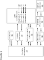
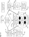
- FIG. 2 shows a simplified functional block diagram of one embodiment of the components located within and connected to the controller 40.
- the components include a control processor 52 which receives input information from various components in order to determine the pacing algorithm in order to treat the patient.
- the control processor is connected to pacing circuitry 53, defibrillation circuitry 55, memory 52, and a telemetry interface 55.
- the pacing circuitry 53 and the defibrillation circuitry 55 connects to the first lead 10, second lead 20, and third lead 30; and ultimately connects to the electrodes, (for example, 18, 28, 34, and 38). These connections allow for multiple capacities to sense electrical activity (such as myocardial depolarizations), deliver pacing stimulations, and/or deliver defibrillation or cardioversion shocks.
- the control processor 51 Based on the input received from the electrodes 18, 28, 34, and 38 through the pacing circuitry 53, the control processor 51 performs calculations to determine the proper course of action, which may include providing ATP therapy to one or more electrodes, providing defibrillation or cardioversion shocks to one or more electrodes through the defibrillation circuitry 55, or no therapy at all.
- the control processor 51 is connected to a telemetry interface 96.
- the telemetry interface can wirelessly send and receive data from an external programmer 62 which is coupled to a display module 64 in order to facilitate communication between the control processor 51 and other aspects of the system external to the patient.
- the control processor 51 may continue to sense electrical activity from one or more electrodes while deliver pacing stimulations to other electrodes.
- the control processor 51 may store selected data to memory 52, and retrieve stored data as necessary. For example, the control processor 51 may identify key aspects of a tachyarrhythmia in order to effectively differentiate the tachycardia and other key aspects of the tachyarrhythmia in order to optimize the best therapy in order to terminate the tachyarrhythmia.
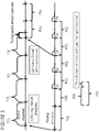
- FIG. 3 is a graphical representation of overdrive pacing from one electrode while sensing electrical depolarizations from a second electrode.
- the Fig helps demonstrate how timing measurements can be performed to estimate the Time to Entrainment.
- the time to entrainment is the total amount of time overdrive pacing must 'gain' on the native tachycardia in order to reach and then accelerate the tachycardia. Therefore, as demonstrated in FIG. 3 , the time to entrainment can be estimated by measuring the timing of sensed electrical activity on a second, distal electrode. For example, if a tachyarrhythmia occurs between two electrodes inside of a heart, one electrode may deliver ATP.
- the second electrode can determine this event.
- the time to entrainment can be estimated by adding the prematurity of each paced stimulation (TCL-PCL) minus the amount of tachycardia acceleration. Therefore, the time to entrainment can be estimated as the (TCL-PCL) times the number of pacing stimulations required to entrain the tachycardia minus the amount of tachycardia acceleration on the first entrained stimulation. There may be delay in the tachycardia due to the shorter paced cycle length.
- This delay can be estimated by slowing the overdrive pacing cycle length, for example the paced cycle length can be prolonged to approximate the tachycardia cycle length.
- Another method to estimate the time to entrainment is by summing the difference in time between the paced stimulations and the sensed depolarizations. Again, conduction delay needs to be taken into account.
- Another method involves measuring the difference in time before pacing and during entrainment (or the first entrainment) between the pacing electrode to the sensing electrode. This time difference is similar to the time described by the N+1 difference (Soejima et al, 2001).
- the time to entrainment can be estimated by the return cycle of a failed ATP attempt minus the tachycardia cycle length.
- the return cycle can also be measured by a specific pacing maneuver designed to determine the time to entrainment while minimizing conduction delay within the circuit.
- the ATP pacing algorithm may deliver a number stimulations until entrainment would likely to have occurred or with evidence of entrainment; followed by deliver of pacing stimulations at a cycle length approximating the tachycardia cycle length.
- the time delay between the stimulation to the sensed electrical depolarization or far-field morphology analyses demonstrated in FIG.
- the Time to Entrainment can also be estimated by two entrainment maneuvers by electrodes on opposite sides of the reentrant circuit.
- the third stimulation brings in the sensed depolarization sensed by the sensing electrode.
- the next interval seen on the sensing electrode has an interval equal to the PCL. This demonstrates that any delay that may have occurred in the paced stimulation on the first entrained stimulation was similar on the second entrained stimulation.
- this delay would suggest conduction delay along the path between the pacing electrode and sensing electrode. This embodiment is discussed in more detail in FIG. 10 ; where this time delay may be utilized to adjust the pacing algorithm in order to facilitate tachycardia termination.
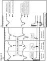
- FIG. 4A and FIG. 4B reveal an example of intracardiac and far-field morphologies which illustrate how far-field morphology analyses can be utilized to estimate the Time to Entrainment.
- FIG. 4A reveals the far-field morphology occurring in three different scenarios. The first column demonstrates the far-field morphology occurring when pacing at baseline (when no underlying tachycardia is present). The second column reveals far-field morphology occurring during a tachycardia. In this figure, the timing of the sensed depolarization occurring on the electrogram can be determined in relation to the far-field morphology. In the third column, the entrained far-field morphology is shown. In FIG.
- the far-field morphologies are superimposed such that the waveforms overlap.
- Various computational algorithms and programs can be performed to determine the various off-set required to minimize the difference between waveforms.
- the waveform analyses can determine the offset required such that the sum of the baseline paced morphology and the baseline tachycardia are arranged such that the sum of these waveforms approximate the entrained tachycardia.
- the time offset between the paced stimulation and the sensed depolarization on the pacing electrode can be used to estimate the Time to Entrainment. As previously mentioned, this time can be used to optimize the pacing algorithm.
- the off-set may prolong indicative of conduction delay occurring within the path of electrical conduction.
- FIG. 5 a simplified diagram of a reentrant tachycardia circuit within a heart and several pacing electrodes for sensing and/or delivering electrical stimulations according to an embodiment of the present invention.
- This figure demonstrates a key concept in utilizing more than one electrode to optimize ATP algorithms.
- the plane of the figure represents myocardial tissue capable of propagating depolarizing wavefronts.
- a reentrant tachycardia can be created which is capable perpetual circular movement through the area of slow conduction and then around the scar.
- the Time to Entrainment is roughly the time it takes for the paced stimulation to leave the pacing location (Time E1 O ) to the "entrance site,” plus the time it takes for electrical activity to leave the native circuit from the "exit site” to the pacing location (Time E1 R ), minus the time it takes to travel in the tachycardia circuit between the exit site and the entrance site (Time E1 Y ).
- the Entrainment Time for electrode E1 is roughly E1 O +E1 R -E1 Y .
- the wavefront created from the pacing location and the wavefront created when leaving the tachycardia exit site.
- These wavefronts collide at various locations depending on circuit morphology, conduction velocities, and other variables.
- the time it takes to conduct electrical signals from one electrode to the others can be measured. For example, pacing from electrode E1 will be sensed by electrodes E2 and E3; and the time delay between stimulation and sensing the depolarizations from these other electrodes can be measured.
- the time delay between the sensed signals occurring between the electrode that will pace (E1) and any other electrode (EX) can be measured during the tachyarrhythmia: ReentrantTime E1->EX .
- the ability of a distal electrode EX to determine the timing of entrainment (as well as Time Delay in the circuit), can be estimated by equation 7 below.
- the Reentrant Time is the difference in time to leave the exit site and travel to both the pacing electrode E1 and any other electrode EX. Cannot verify entrainment if : Time to entrainment ⁇ TCL ⁇ PCL ⁇ Time Delay > Stim Time E 1 ⁇ EX ⁇ Reentrant Time E 1 ⁇ EX
- the probability of having an electrode capable of sensing entrainment is increased. Furthermore, even when the electrode satisfies equation 7; the timing of sensing local signals can be missed [blanked] if the sensing occurs simultaneously with the timing of pacing. Therefore, additional electrodes, even close in proximity, can augment the probability the timing of entrainment can be determined, as well as estimation of Time Delay within the circuit. Furthermore, if the pacing entrance site is close in proximity to the tachycardia exit site, far-field morphology analyses may be limited in its ability to estimate the Time to Entrainment and potential Time Delay.
- the system can estimate entrainment, time delays in the circuit, and tachycardia termination. By correctly measuring and/or estimating these components, ATP pacing algorithms do not need to stop pacing until the tachyarrhythmia is terminated. This describes another example in which ATP algorithms can be optimized to more rapidly and efficiently terminate tachyarrhythmias.
- the system may be able to design the initial anti-tachycardia pacing algorithm based on some measurements. For example, by recording the baseline conduction time from the pacing electrode to at least one additional electrode, and measuring the difference in time between these two electrodes during an episode of tachycardia, the Time to Entrainment may be estimated as the difference of these measurements.
- This method requires certain assumptions regarding the reentrant circuit and its relationship to the pacing electrodes; however, this method creates a rapid initial ATP algorithm that has a high probability of tachycardia termination.
- having the device routinely measure conduction times between electrodes the device may monitor and assess for ischemic episodes. This is because ischemia can change conduction times. Therefore, during a myocardial infarction, the conduction times may change. Therefore, monitoring conduction times may serve as an indicator of ischemia and can alert the patient or care-takers to take action.
- FIG. 6 reveals the relationship between the coupling intervals during a pacing drivetrain and the effective refractory period, also known as the electrical restitution curve.
- FIG. 6 demonstrates a typical electrical restitution curve seen in ventricular myocardial tissue.
- a pacing train was performed at two cycle lengths, 400ms and 600ms.
- a coupling stimulation was delivered at various intervals (x-axis) which was followed by a second stimulation S2.
- the coupling interval predicts the interval of the second stimulus that fails to capture the myocardium (the effective refractory period or ERP). Note how significantly a single coupling interval dramatically affects the ERP of the second premature stimulus.
- a single stimulus at 230ms is refractory (does not conduct) in the majority of patients.
- the stimulus at 230ms no longer is refractory for any of the patients in this study.
- the second stimulus needs to shorten by over 40ms, and stimulate at less than 190ms in order to reach refractoriness.
- the electrical restitution curve reveals how dramatically repolarization rates are determined by the previous depolarization interval.
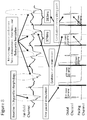
- FIG. 7 is a graphical representation demonstrating the relationship between the pacing prematurity (TCL-PCL), the number of pacing stimulations, the Time to Entrainment, and the amount of tachycardia acceleration on the first entrained stimulation.
- TCL-PCL pacing prematurity
- This figure demonstrates the importance the electrical restitution curve in designing ATP algorithms.
- ATP In order to 'gain' on the native tachycardia, ATP must pace faster than the TCL.
- Each paced stimulation gains on the tachycardia by the difference between the TCL and the PCL (the "pacing prematurity).
- ATP or overdrive pacing begins to accelerate the tachycardia when the sum of the pacing prematurity is greater than the Time to Entrainment.
- the first stimulation that accelerates the tachycardia can shorten the TCL by any amount between the TCL and the PCL. With perpetual pacing, the entire tachyarrhythmia will accelerate to the PCL; however, the first stimulation that entrains the tachycardia may only partially accelerate to the PCL. Since the goal of ATP is to reach electrical refractoriness within the reentrant circuit; this partial acceleration can prepare the tissue involved in the reentrant circuit to repolarize more quickly. Based on mathematically modeling and empirical testing, the amount of acceleration on the first entrained stimulation will dramatically effect whether or not the tachyarrhythmia is terminated at any given PCL.
- the prematurity can be arranged such that the first stimulation that accelerates the tachycardia will accelerate the tachycardia to the desired PCL. This arrangement can minimize the partial acceleration occurring on the first entrained stimulation; and help optimize the probability of tachycardia termination.
- FIG. 8 reveals an example of utilizing intracardiac measurements and far-field morphology analyses to determine the Time to Entrainment and Time Delay within the circuit taken from an ATP attempt from an epicardial electrode.
- two electrodes are located on roughly opposite sides of a reentrant tachycardia. Pacing is initiated, and the third stimulation reveals the signal was brought in on the distal electrode channel.
- various measurements can be performed at this point to estimate the Time to Entrainment.
- far-field morphology analysis revealed (as previously discussed in FIG. 4 ) the overlapping time gain to accelerate by less than predicted by the difference between the TCL and PCL; and therefore the entrainment time can be estimated.
- the fourth stimulation also entrained the reentrant tachycardia, however, the stim to sense timing prolonged from 281ms to 290ms.
- the stim to far-field minimum also prolonged by 9ms. Therefore there was 9ms delay somewhere between the pacing electrode and the sensing electrode, usually in areas of slow conduction. These areas of slow conduction usually occur at critical aspects of the reentry tachycardia.
- the device can sense this delay in conduction and continue pacing as long as conduction delay continues to prolong from overdrive pacing (as evidenced from far-field morphology analyses or at least one additional electrode). The device can therefore estimate and record the Time Delay that is occurring.
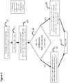
- FIG. 9 reveals a flow chart of one embodiment to determine the ATP therapy.
- the device assesses and records the baseline conduction times to various electrodes and pacing morphologies from one or more of the electrodes when the patient is not in tachycardia. These measurements are used for reference when determining if ATP therapies are able to determine entrainment from additional electrodes or far-field pacing morphology analyses.
- Step 2 the device is programmed to monitor for tachycardia.
- Step 3 the device determines the patient is now in a tachyarrhythmia.
- the criteria of determining criteria for tachycardia have been previously described.
- using the timing differences between more than one electrode; and the timing differences between far-field morphology analyses and local activation can help identify and mathematically describe tachyarrhythmias.
- these specific measurements can be recorded and used to identify and differentiate tachyarrhythmias.
- the device can record the Time to Entrainment from one or additional electrodes and record the Time to Entrainment for a specific electrode for a specific tachyarrhythmia.
- Step 4 the device assesses whether the newly identified tachyarrhythmia has been previously identified. As mentioned, this is determined by comparing time differences and morphology analyses. If the tachycardia has not been previously identified, we move to Step 5, where the initial ATP algorithm is determined based on the tachycardia cycle length and timing differences between electrodes. For example, the ability to determine entrainment is related to the difference in time between the sensed local activation and the paced time delays between electrodes. The device could determine which electrodes have the greatest probability of being located on opposite sides of the reentrant circuit. In addition, the device may be programmed to deliver ATP from the latest (or earliest) local activation or in relation to baseline timing differences.
- Step 6 If the original tachycardia had been previously identified, we move from Step 4 to Step 6. In this Step, previously successful and unsuccessful ATP attempts can be incorporated into the device to determine the first ATP pacing algorithm.
- recorded Time to Entrainments for this particular tachycardia can be used such that the pacing prematurity is arranged such that the first pacing stimulation to accelerate the native reentrant circuit fully accelerates the reentrant circuit by the difference between the TCL and the chosen PCL. In this manner, partial acceleration is minimized.
- the first stimulation that accelerates the tachycardia can be shortened if prior attempts failed to terminate on the first accelerating stimulation.
- the pacing prematurity can be arranged to facilitate local capture. This can be done by gradually increasing the pacing prematurity as a way of 'priming' local myocardium to accept the shorter paced cycle length.
- Step 5 and Step 6 move to Step 7 and deliver the ATP as programmed. Timing delays from distal electrodes, far-field analyses, and evoked potentials can be used to determine local capture. Additionally, the return cycle can be used to determine if the pacing stimulations captured the myocardium. Additionally, the exact stimulation which did not capture the myocardium can be identified and used to adjust the ATP pacing strategy.
- FIG. 10 further reveals a flow chart of one embodiment that may occur once the device delivers ATP in Step 7.
- the device may monitor and/or perform far-field morphology analyses and the time measurement from the timing of stimulation to local capture measured from electrodes. Until entrainment occurs, these measured times should prolong by the pacing prematurity unless the stimulated wavefront time directly reaches the electrodes. This time measurement, as previously described, is recorded prior to the patient going into the tachyarrhythmia. Therefore, the device can determine if the measured premature signal occurs from direct signal propagation versus the entrained wavefront from the native tachycardia.
- Step 9 during an ATP attempt, the device is constantly assessing for evidence of tachycardia termination, a significant change in the tachyarrhythmia, or tachycardia acceleration. If either of these circumstances are met, the device may stop pacing and re-assess the rhythm as in Step 10. Tachyarrhythmia termination, change, or acceleration may be monitored by far-field morphology analyses and/or the rate and relationship among sensed signals from various electrodes.
- Step 11 once the ATP is stopped, the device will measure the return cycle length, determine if the patient remains in a tachyarrhythmia, categorize the most recent pacing strategy was successful or unsuccessful at terminating the tachyarrhythmia. If unsuccessful, the device may shorten the pacing cycle length (PCL) to be more aggressive or change the pacing location depending on the settings programmed into the device.
- PCL pacing cycle length
- the device may obtain evidence that the ATP attempt has successfully entrained the tachyarrhythmia as in Step 12. At this point, the device will estimate the Time to Entrainment for this identified tachyarrhythmia and use this measurement should this tachyarrhythmia be identified again and attempt to deliver therapy. In one embodiment, the device proceeds to Step 13, where the device continues to deliver pacing stimulations as long as the device measures a prolonging Time Delay.
- the Time Delay is estimated by a prolongation of stimulation to sensed signal (either from a second electrode or from far-field morphology analyses). The amount of prolongation the device identifies as significant can be preprogrammed and adjustable.
- the first stimulation that does not conduct through the arrhythmic circuit in the orthograde direction can be detected by the device in terms of far-field morphology or a distal electrode as long as the conduction times satisfy equation 7 at which point the device may transition to Step 9.
- the device may deliver one or more stimulations at the TCL plus the amount of measured Time Delay as in Step 14.
- the device may deliver this priming stimulation at an interval that is determined by the TCL and/or the Time Delay but not necessarily the TCL or the sum of the TCL plus the Time Delay.
- This priming stimulation prolongs the interval seen by critical aspects of the reentrant circuit while maintaining access to the arrhythmic circuit by the pacing electrode.
- the device can then deliver a pacing stimulation at a shorter pacing cycle length with an increased probability of tachycardia termination. This interval may be the same pacing cycle length (PCL) as the prior pacing stimulation(s) or may be adjusted based on programmable or algorithmic features.
- PCL pacing cycle length
- the device may transition back to Step 13 and continue pacing at the PCL; or the device may proceed to Step 15, where the device may shorten the PCL after the priming stimulation.
- the device may deliver additional priming stimulations, change the pacing location, or stop pacing altogether.
- the decision tree can be adjustable based on the TCL and prior attempts. That is, with shorter TCL, the device may be more aggressive by shortening the PCL rapidly. Alternatively, if the tachyarrhythmia is prone to tachycardia acceleration or fibrillation, the device may shorten the PCL more gradually.
- each of the steps S13, S14, and S15 are all working in tandem such that the device is delivering ATP while adjusting the ATP based on measured responses from other electrodes or far-field morphology analyses. Furthermore, the device may sense changes in the signals consisted with tachycardia termination (moving to Step 9) or lose the ability to identify termination, in which case the system moves to Step 10.
- Step 10 the timing relationships between electrodes do not satisfy equation 7; or the far-field morphology analyses reveals the pacing morphology (gradual fusion) to match the morphology with isolated pacing in the absence of an underlying tachycardia.
- This can occur when the tachycardia morphology is similar to the paced morphology from the pacing electrode or when the entrance and exit locations for the entrained tachycardia are close in proximity.
- the device cannot definitively determine when the tachycardia has terminated or accelerated. Therefore, the device must occasionally stop delivery of ATP in order to assess the heart and the rhythm. In these circumstances, the device may move to Step 16, where ATP is driven by protocol.
- the device can deliver enough pacing stimulations sufficient to obtain entrainment.
- the device may deliver one or more stimulations close to the TCL ("priming stimulations") followed by one or more stimulations at a shorter cycle length.
- the device may simply stop ATP and (moving to Step 17), measure the return cycle (the post-pacing interval). This interval can be used to 1) verify the tachycardia was entrained and 2) determine the Time to Entrainment.
- the resulting return cycle length can be measured as well as any Time Delay associated with the shorter cycle lengths.
- a priming stimulation utilizing the Time Delay can be delivered to facilitate tachycardia termination even when entrainment cannot be verified during pacing.
- the Time to Entrainment can be used to arrange the initial pacing stimulations to minimize partial acceleration on the first accelerating pacing stimulation.
- the device can return to Step 2 and assess the tachyarrhythmia.
- the device can identify if the prior ATP strategy was successful or unsuccessful and use this information to guide the ATP algorithm.
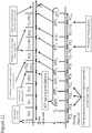
- FIG. 11 is a graphical representation of deliver an anti-tachycardia pacing therapy according to one embodiment of the present invention.
- Depolarizations or signals sensed by the pacing channel electrode are labeled S1 and S2.
- the distal channel electrode has a line when it senses depolarizations or signals.
- ATP pulses are labeled with ATP1 being the first pacing stimulation and ATP9 is the last pacing stimulation.
- the time interval between the first and second sensed signals is the tachycardia cycle length (TCL).
- TCL the timing differences between electrodes, and the far-field morphology (not shown) can be used to identify the tachycardia ("Tachycardia Identifiers").
- the sensed signals can alert the Control Processor of the tachycardia and determines the ATP pacing strategy.
- the device begins delivering ATP pulses. If the Time to Entrainment had previously been recorded for this tachycardia, the device would arrange the initial pacing prematurity such that the sum prematurity is equal to the Time to Entrainment. The following pacing stimulation would then completely accelerate the arrhythmic circuit by the pacing prematurity of that paced stimulation (TCL-PCL).
- the third pacing stimulation brings in the sensed signal on the distal channel. Assuming this time is shorter than the previously recorded conduction time between these electrodes, this would suggest the tachycardia has been entrained, which may signal to the processor the tachycardia is now being advanced by the pacing stimulations.
- the pacing prematurities can be summed to the point of tachycardia advancement to estimate the Time to Entrainment; alternatively the difference in time from the Stim to sensed signal on the distal channel between the first entrained stimulation and the baseline tachycardia can be used to estimate the Time to Entrainment.
- the device delivers a "Priming" stimulation, by delivering a stimulation with the interval of the TCL plus the TD1 (or some percentage of the TCL plus the TD1). In yet another embodiment, the device may deliver one or more pacing stimulations at the original tachycardia cycle length or substantially similar to the tachycardia cycle length.
- this "priming" stimulation can deliver one or more pacing stimulations at or near the TCL.
- the device then delivers a pacing stimulation with a shorter interval.
- the tachycardia does not terminate (there is a sensed signal from ATP 7) and there was no measured conduction delay (the interval equals the PCL).
- the device could have continued delivering ATP therapy at the same PCL.
- the device delivers a second "priming" stimulation, followed by a PCL at a shorter cycle length (PCL2).
- the sensed signal on the distal channel does not sense a signal (the amount of delay deemed significant can be programmed) and therefore can identify the tachycardia as terminated and pacing is stopped in order to assess the rhythm.
- the Time Delay measured occurs from conduction changes or circuit changes at locations other than the arrhythmic circuit, for example, near the pacing electrode.
- delivering priming stimulations at the TCL plus the TD1 will result in loss of entrainment to the arrhythmic circuit.
- the time interval between the stimulation and the sensed signal on the distal channel can be used to identify and the ATP pacing algorithm can be adjusted to correct for this.
- the sensed signals sometimes occur simultaneously with the ATP stimulations. When this occurs, crosstalk can prevent this signal from being measured. Therefore, as previously discussed, sensing from more than one sensing channels can help monitor the tachyarrhythmia during ATP therapy.
- the multiple sensing electrodes can be used in combination (and in conjunction with far-field morphology analyses) to assess for entrainment, conduction delay, and changes in the tachyarrhythmia (such as termination or acceleration). Therefore, in one embodiment, catheters with two or more electrodes are described in order to sense cardiac depolarizations from more than one location in order to avoid sensing issues (blanking), which may occur when otherwise sensing from one location.
Landscapes
- Health & Medical Sciences (AREA)
- Cardiology (AREA)
- Heart & Thoracic Surgery (AREA)
- Life Sciences & Earth Sciences (AREA)
- General Health & Medical Sciences (AREA)
- Engineering & Computer Science (AREA)
- Biomedical Technology (AREA)
- Nuclear Medicine, Radiotherapy & Molecular Imaging (AREA)
- Radiology & Medical Imaging (AREA)
- Animal Behavior & Ethology (AREA)
- Public Health (AREA)
- Veterinary Medicine (AREA)
- Biophysics (AREA)
- Physiology (AREA)
- Hematology (AREA)
- Electrotherapy Devices (AREA)
- Measurement And Recording Of Electrical Phenomena And Electrical Characteristics Of The Living Body (AREA)
Claims (12)
- System zur Abgabe von Therapie zur Beendigung eines Tachykardieereignisses in einem Herzen eines Patienten, umfassend:eine Schrittmachervorrichtung, die konfiguriert ist, um in den Körper des Patienten implantiert zu werden, und die einen Prozessor (40, 51) umfasst;eine Vielzahl von Elektroden (18, 28, 34), die mit dem Prozessor gekoppelt und dimensioniert sind zur Implantation in den Körper des Patienten, wobei der Prozessor zu Folgendem konfiguriert ist:Erfassen von Herzsignalen aus dem Herzen und Erkennen eines Tachykardieereignisses als Reaktion auf die erfassten Herzsignale;Abgabe von einem oder mehreren Schrittmacherimpulsen über eine oder mehrere Schrittmacherelektroden an das Herz, wobei die Schrittmacherimpulse eine oder mehrere Schrittmacherzykluslängen aufweisen;Überwachung von Herzsignalen während der Abgabe des einen oder der mehreren Schrittmacherimpulse, um die Beendigung/Blockierung einer Tachykardie innerhalb der ablaufinvarianten Schaltung zu erkennen; undEinstellen der Abgabe des einen oder der mehreren Schrittmacherimpulse als Reaktion auf die überwachten Herzsignale,wobei die Tachykardie-Beendigung/-Blockierung innerhalb der ablaufinvarianten Schaltung durch den Prozessor durch Überwachen von Herzsignalen unter Verwendung einer oder mehrerer Sensorelektroden, die anders sind als die eine oder die mehreren Schrittmacherelektroden, erkannt wird.
- System nach Anspruch 1, wobei der Prozessor ferner konfiguriert ist, um ein oder mehrere Leitungsintervalle von der einen oder den mehreren Schrittmacherelektroden zu der einen oder den mehreren Sensorelektroden aufzuzeichnen, wenn nicht in einer ablaufinvarianten Tachykardie befindlich, um die Überwachung der ablaufinvarianten Tachykardie zu unterstützen.
- System nach Anspruch 1, wobei der Prozessor konfiguriert ist, um die Beendigung/ Blockierung einer Tachykardie innerhalb der ablaufinvarianten Schaltung durch Messen dynamischer Reaktionen zu erkennen, die aus den Taktintervallen von Herzsignalen aus der einen oder den mehreren Sensorelektroden auftreten, die anders sind als die eine oder die mehreren Schrittmacherelektroden.
- System nach Anspruch 1, wobei das Überwachen des/der Herzsignale(s) während der Abgabe des einen oder der mehreren Schrittmacherimpulse das Messen eines Zeitintervalls zwischen den erfassten Herzsignalen durch die eine oder die mehreren Messelektroden umfasst.
- System nach Anspruch 4, wobei der Prozessor konfiguriert ist, um die Beendigung/ Blockierung einer Tachykardie innerhalb der ablaufinvarianten Schaltung durch Überwachung von Änderungen in Zeitintervallen zwischen den erfassten Herzsignalen durch die eine oder die mehreren Messelektroden während der Abgabe des einen oder der mehreren Schrittmacherimpulse zu erkennen.
- System nach Anspruch 1, wobei das Überwachen von Herzsignal(en) während der Abgabe des einen oder der mehreren Schrittmacherimpulse das Messen eines Zeitintervalls zwischen der Stimulation durch die eine oder die mehreren Schrittmacherelektroden und den durch die eine oder die mehreren Sensorelektroden erfassten Herzsignalen umfasst.
- System nach Anspruch 6, wobei der Prozessor konfiguriert ist, um die Beendigung/ Blockierung einer Tachykardie innerhalb der ablaufinvarianten Schaltung durch Überwachen von Änderungen in Zeitintervallen zwischen der Stimulation durch die eine oder die mehreren Schrittmacherelektroden und den durch die eine oder die mehreren Messelektroden erfassten Herzsignalen während der Abgabe des einen oder der mehreren Schrittmachtimpulse zu erkennen.
- System nach Anspruch 2, wobei der Prozessor ferner konfiguriert ist, um abzuschätzen, wann die Tachykardie durch Schrittmacherimpulse vorangetrieben/weitergeführt wurde, weiterhin Schrittmacherimpulse bei Zykluslängen abzugeben, die im Wesentlichen dem einen oder den mehreren Schrittmacherzykluslängen ähnlich sind, und die Zeitverzögerung, die einer Leitungsverzögerung innerhalb und außerhalb der ablaufinvarianten Schaltung entspricht, durch Messen von Intervalländerungen zwischen der einen oder den mehreren Schrittmacherelektroden und der mindestens einen Messelektrode zu messen.
- System nach Anspruch 8, wobei der Prozessor ferner konfiguriert ist, um weiterhin Schrittmacherimpulse mit der gleichen oder ähnlichen Schrittmacherzykluslänge abzugeben, bis der Betrag der gemessenen Zeitverzögerung für zwei aufeinanderfolgende Impulse innerhalb eines bestimmten Schwellenwerts unverändert ist.
- System nach Anspruch 9, wobei der Prozessor ferner konfiguriert ist, um die Abgabe von Schrittmacherimpulsen einzustellen, um einen oder mehrere Starterimpulse mit einem oder mehreren Starterimpulsintervallen einzuschließen, die länger sind als die eine oder die mehreren Schrittmacherzykluslängen, die verwendet werden, um die Tachykardie über die eine oder die mehreren Schrittmacherelektroden voranzutreiben/weiterzuführen, und danach Abgabe von mindestens einem Beschleunigungsimpuls mit einem oder mehreren Beschleunigungsimpulsintervallen, die kürzer sind als der eine oder die mehreren Starter-Schrittmacherimpulsintervalle, an das Herz über die eine oder die mehreren Elektroden.
- System nach Anspruch 10, wobei der Prozessor ferner konfiguriert ist, um die Starterimpuls-Zykluslänge zumindest teilweise durch die gemessene Zeitverzögerung und die Tachykardie-Zykluslänge zu bestimmen.
- System nach Anspruch 11, wobei der Prozessor ferner so konfiguriert ist, dass, wenn der Prozessor weder die Tachykardie als beendet erkennt noch die Fähigkeit verliert, die Beendigung der Tachykardie zu erkennen, der Prozessor weiterhin zwischen der Abgabe mindestens eines Starterimpulses mit einem längeren Impulsintervall gefolgt von mindestens einem Beschleunigungsimpuls bei einem kürzeren Impulsintervall wechselt; und wobei mindestens ein Beschleunigungsimpulsintervall mit jeder Iteration so verkürzt wird, dass der gemessene Zeitverzögerungsbetrag für aufeinanderfolgende Beschleunigungsschrittmacherimpulse innerhalb eines festgelegten Schwellenwerts unverändert ist.
Applications Claiming Priority (2)
| Application Number | Priority Date | Filing Date | Title |
|---|---|---|---|
| US201462030520P | 2014-07-29 | 2014-07-29 | |
| PCT/US2015/042536 WO2016018945A1 (en) | 2014-07-29 | 2015-07-28 | Systems and methods to optimize anti-tachycardial pacing (atp) |
Publications (3)
| Publication Number | Publication Date |
|---|---|
| EP3174459A1 EP3174459A1 (de) | 2017-06-07 |
| EP3174459A4 EP3174459A4 (de) | 2018-03-14 |
| EP3174459B1 true EP3174459B1 (de) | 2019-09-04 |
Family
ID=55178975
Family Applications (1)
| Application Number | Title | Priority Date | Filing Date |
|---|---|---|---|
| EP15826371.5A Active EP3174459B1 (de) | 2014-07-29 | 2015-07-28 | Systeme zur optimierung von anti-tachykardien-stimulation (atp) |
Country Status (4)
| Country | Link |
|---|---|
| US (3) | US9795789B2 (de) |
| EP (1) | EP3174459B1 (de) |
| JP (1) | JP6795501B2 (de) |
| WO (1) | WO2016018945A1 (de) |
Families Citing this family (16)
| Publication number | Priority date | Publication date | Assignee | Title |
|---|---|---|---|---|
| US10028670B1 (en) | 2014-01-14 | 2018-07-24 | CardioFlow Technologies, LLC | Apparatus and methods for optimizing volume status and cardiac output |
| US9795789B2 (en) * | 2014-07-29 | 2017-10-24 | CardioFlow Technologies, LLC | Systems and methods to optimize anti-tachycardial pacing (ATP) |
| US9737223B2 (en) | 2015-05-13 | 2017-08-22 | Medtronic, Inc. | Determining onset of cardiac depolarization and repolarization waves for signal processing |
| WO2016196412A1 (en) * | 2015-05-30 | 2016-12-08 | CardioFlow Technologies, LLC | Apparatus and methods for optimizing intra-cardiac filling pressures through controlled regurgitation |
| US9610045B2 (en) | 2015-07-31 | 2017-04-04 | Medtronic, Inc. | Detection of valid signals versus artifacts in a multichannel mapping system |
| US9782094B2 (en) | 2015-07-31 | 2017-10-10 | Medtronic, Inc. | Identifying ambiguous cardiac signals for electrophysiologic mapping |
| WO2017136609A1 (en) * | 2016-02-02 | 2017-08-10 | Cardioflaw Technologies, Llc | Systems and methods to improve anti-tachycardial pacing (atp) algorithms |
| US11027132B2 (en) * | 2016-03-16 | 2021-06-08 | Medtronic, Inc. | Synchronization of anti-tachycardia pacing in an extra-cardiovascular implantable system |
| US10201710B2 (en) * | 2016-04-28 | 2019-02-12 | Medtronic, Inc. | Latency-based adaptation of anti-tachyarrhythmia pacing therapy |
| WO2018017900A1 (en) * | 2016-07-20 | 2018-01-25 | CardioFlow Technologies, LLC | Apparatus and methods for optimizing intra-cardiac pressures for improved exercise capacity |
| US10675471B2 (en) | 2017-08-15 | 2020-06-09 | Medtronic, Inc. | Anti-tachycardia pacing control in an implantable medical device system |
| EP3456258A1 (de) * | 2017-09-14 | 2019-03-20 | Fishel, Robert S. | Automatisierte elektroanatomische kennzeichnung positiver entrainmentgebiete zur abbildung aktiver wiedereintrittskreisläufe |
| US11419539B2 (en) | 2017-12-22 | 2022-08-23 | Regents Of The University Of Minnesota | QRS onset and offset times and cycle selection using anterior and posterior electrode signals |
| US10765876B2 (en) | 2018-04-27 | 2020-09-08 | Medtronic, Inc. | Method and apparatus for delivering anti-tachycardia pacing |
| US11951319B2 (en) * | 2018-08-07 | 2024-04-09 | Pacesetter, Inc. | Systems and methods for applying anti-tachycardia pacing using subcutaneous implantable cardioverter-defibrillators |
| DE102019110283A1 (de) * | 2019-04-18 | 2020-10-22 | Biotronik Se & Co. Kg | Implantierbare Anordnung zur diagnostischen und/oder therapeutischen Behandlung eines menschlichen oder tierischen Patienten |
Family Cites Families (16)
| Publication number | Priority date | Publication date | Assignee | Title |
|---|---|---|---|---|
| SE9202825D0 (sv) * | 1992-09-30 | 1992-09-30 | Siemens Elema Ab | Hjaertstimulator |
| US6654639B1 (en) * | 2001-05-07 | 2003-11-25 | Pacesetter, Inc. | Method and device for multi-chamber cardiac pacing in response to a tachycardia |
| EP1429839A2 (de) * | 2001-08-28 | 2004-06-23 | Medtronic, Inc. | Implantierbare medizinische vorrichtung zur behandlung von mechanischen herzfunktionsstörungen durch elektrische stimulation |
| US6766196B1 (en) * | 2001-10-19 | 2004-07-20 | Pacesetter, Inc. | Anti-tachycardia pacing methods and devices |
| US7107098B2 (en) * | 2003-02-20 | 2006-09-12 | Medtronic, Inc. | Method and apparatus for generation and selection of tachycardia therapy hierarchy |
| US7392082B2 (en) * | 2003-09-26 | 2008-06-24 | Medtronic, Inc. | Inter-episode implementation of closed loop ATP |
| US7496402B2 (en) * | 2004-04-29 | 2009-02-24 | Cardiac Pacemakers, Inc. | ATP pacing with entrainment monitoring |
| WO2006039693A1 (en) * | 2004-09-30 | 2006-04-13 | Cardiac Pacemakers, Inc. | Cardiac activation sequence monitoring and tracking |
| US7761155B2 (en) * | 2006-02-15 | 2010-07-20 | Medtronic, Inc. | Method and device for delivering anti-tachycardia pacing therapy |
| US8401628B2 (en) * | 2008-06-04 | 2013-03-19 | Cardiac Pacemakers, Inc. | Sensing vector configuration in ICD to assist arrhythmia detection and annotation |
| US8328728B2 (en) * | 2008-08-22 | 2012-12-11 | Pacesetter, Inc. | Implantable hemodynamic monitor and methods for use therewith |
| US8332032B2 (en) * | 2009-01-23 | 2012-12-11 | Medtronic, Inc. | Hybrid single-chamber to simultaneous pacing method for discrimination of tachycardias |
| US8064999B2 (en) * | 2009-01-30 | 2011-11-22 | Medtronic, Inc. | Distance-based analysis of return cycles for tachycardia discrimination |
| US9510764B2 (en) * | 2009-04-22 | 2016-12-06 | Cardiac Pacemakers, Inc. | Methods for detecting atrial tachyarrhythmia in implantable devices without dedicated atrial sensing |
| US8812107B2 (en) * | 2010-06-29 | 2014-08-19 | Medtronic, Inc. | Terminating tachyarrhythmias |
| US9795789B2 (en) * | 2014-07-29 | 2017-10-24 | CardioFlow Technologies, LLC | Systems and methods to optimize anti-tachycardial pacing (ATP) |
-
2015
- 2015-07-28 US US14/811,719 patent/US9795789B2/en active Active
- 2015-07-28 WO PCT/US2015/042536 patent/WO2016018945A1/en active Application Filing
- 2015-07-28 JP JP2017526044A patent/JP6795501B2/ja active Active
- 2015-07-28 EP EP15826371.5A patent/EP3174459B1/de active Active
-
2017
- 2017-10-23 US US15/791,043 patent/US10350415B2/en active Active
-
2019
- 2019-07-15 US US16/512,248 patent/US11090492B2/en active Active
Non-Patent Citations (1)
| Title |
|---|
| None * |
Also Published As
| Publication number | Publication date |
|---|---|
| EP3174459A4 (de) | 2018-03-14 |
| WO2016018945A1 (en) | 2016-02-04 |
| JP2017529197A (ja) | 2017-10-05 |
| US20200009381A1 (en) | 2020-01-09 |
| EP3174459A1 (de) | 2017-06-07 |
| US11090492B2 (en) | 2021-08-17 |
| JP6795501B2 (ja) | 2020-12-02 |
| US20160030743A1 (en) | 2016-02-04 |
| US20180117325A1 (en) | 2018-05-03 |
| US10350415B2 (en) | 2019-07-16 |
| US9795789B2 (en) | 2017-10-24 |
Similar Documents
| Publication | Publication Date | Title |
|---|---|---|
| US11090492B2 (en) | Systems and methods to optimize anti-tachycardial pacing (ATP) | |
| US8449472B2 (en) | Neurostimulation and neurosensing techniques to optimize atrial anti-tachycardia pacing for prevention of atrial tachyarrhythmias | |
| US7233824B2 (en) | Secure and efficacious therapy delivery for an extra-systolic stimulation pacing engine | |
| US7962209B2 (en) | Method and system for characterizing supraventricular rhythm during cardiac pacing | |
| US7715915B1 (en) | Neurostimulation and neurosensing techniques to optimize atrial anti-tachycardia pacing for prevention of atrial tachyarrhythmias | |
| US9700729B2 (en) | Criteria for optimal electrical resynchronization during biventricular pacing | |
| US7085599B2 (en) | Characterization of supraventricular rhythm using collected cardiac beats | |
| EP2139554B1 (de) | Unterscheidung zwischen supraventikulärer tachykardie und ventrikulärer tachykardie | |
| EP2004284B1 (de) | Vorrichtung zur verabreichung einer anti-tachykardie-schrittmachertherapie | |
| CA2524183A1 (en) | Method for elimination of ventricular pro-arrhythmic effect caused by atrial therapy | |
| JP2009519808A (ja) | 血行力学的に制御された抗頻脈性不整脈ペーシングシステム | |
| US20120109240A1 (en) | Automatic adjustment of arrhythmia detection parameters | |
| US8417335B2 (en) | Synchronized ventricular pacing to promote atrial sensing | |
| US20170209696A1 (en) | Systems and methods to improve anti-tachycardial pacing (atp) algorithms | |
| US11278728B2 (en) | Identify insulation breach using electrograms | |
| EP3160575B1 (de) | Implantierbares medizinisches system und verfahren zum identifizieren von isolationsverletzungen mittels elektrogrammen | |
| WO2017136609A1 (en) | Systems and methods to improve anti-tachycardial pacing (atp) algorithms |
Legal Events
| Date | Code | Title | Description |
|---|---|---|---|
| STAA | Information on the status of an ep patent application or granted ep patent |
Free format text: STATUS: THE INTERNATIONAL PUBLICATION HAS BEEN MADE |
|
| 17P | Request for examination filed |
Effective date: 20170227 |
|
| AK | Designated contracting states |
Kind code of ref document: A1 Designated state(s): AL AT BE BG CH CY CZ DE DK EE ES FI FR GB GR HR HU IE IS IT LI LT LU LV MC MK MT NL NO PL PT RO RS SE SI SK SM TR |
|
| AX | Request for extension of the european patent |
Extension state: BA ME |
|
| PUAI | Public reference made under article 153(3) epc to a published international application that has entered the european phase |
Free format text: ORIGINAL CODE: 0009012 |
|
| STAA | Information on the status of an ep patent application or granted ep patent |
Free format text: STATUS: REQUEST FOR EXAMINATION WAS MADE |
|
| DAV | Request for validation of the european patent (deleted) | ||
| DAX | Request for extension of the european patent (deleted) | ||
| A4 | Supplementary search report drawn up and despatched |
Effective date: 20180213 |
|
| RIC1 | Information provided on ipc code assigned before grant |
Ipc: A61B 5/00 20060101ALI20180208BHEP Ipc: A61N 1/365 20060101ALI20180208BHEP Ipc: A61N 1/362 20060101AFI20180208BHEP Ipc: A61B 5/0464 20060101ALI20180208BHEP Ipc: A61B 5/0402 20060101ALI20180208BHEP |
|
| REG | Reference to a national code |
Ref country code: DE Ref legal event code: R079 Ref document number: 602015037401 Country of ref document: DE Free format text: PREVIOUS MAIN CLASS: A61B0005040200 Ipc: A61N0001362000 |
|
| GRAP | Despatch of communication of intention to grant a patent |
Free format text: ORIGINAL CODE: EPIDOSNIGR1 |
|
| STAA | Information on the status of an ep patent application or granted ep patent |
Free format text: STATUS: GRANT OF PATENT IS INTENDED |
|
| RIC1 | Information provided on ipc code assigned before grant |
Ipc: A61B 5/00 20060101ALI20190301BHEP Ipc: A61N 1/365 20060101ALI20190301BHEP Ipc: A61B 5/0464 20060101ALI20190301BHEP Ipc: A61N 1/362 20060101AFI20190301BHEP Ipc: A61B 5/0402 20060101ALI20190301BHEP |
|
| INTG | Intention to grant announced |
Effective date: 20190327 |
|
| GRAS | Grant fee paid |
Free format text: ORIGINAL CODE: EPIDOSNIGR3 |
|
| GRAA | (expected) grant |
Free format text: ORIGINAL CODE: 0009210 |
|
| STAA | Information on the status of an ep patent application or granted ep patent |
Free format text: STATUS: THE PATENT HAS BEEN GRANTED |
|
| AK | Designated contracting states |
Kind code of ref document: B1 Designated state(s): AL AT BE BG CH CY CZ DE DK EE ES FI FR GB GR HR HU IE IS IT LI LT LU LV MC MK MT NL NO PL PT RO RS SE SI SK SM TR |
|
| REG | Reference to a national code |
Ref country code: GB Ref legal event code: FG4D |
|
| REG | Reference to a national code |
Ref country code: CH Ref legal event code: EP |
|
| REG | Reference to a national code |
Ref country code: AT Ref legal event code: REF Ref document number: 1174517 Country of ref document: AT Kind code of ref document: T Effective date: 20190915 |
|
| REG | Reference to a national code |
Ref country code: DE Ref legal event code: R096 Ref document number: 602015037401 Country of ref document: DE |
|
| REG | Reference to a national code |
Ref country code: IE Ref legal event code: FG4D |
|
| REG | Reference to a national code |
Ref country code: NL Ref legal event code: MP Effective date: 20190904 |
|
| REG | Reference to a national code |
Ref country code: LT Ref legal event code: MG4D |
|
| PG25 | Lapsed in a contracting state [announced via postgrant information from national office to epo] |
Ref country code: FI Free format text: LAPSE BECAUSE OF FAILURE TO SUBMIT A TRANSLATION OF THE DESCRIPTION OR TO PAY THE FEE WITHIN THE PRESCRIBED TIME-LIMIT Effective date: 20190904 Ref country code: LT Free format text: LAPSE BECAUSE OF FAILURE TO SUBMIT A TRANSLATION OF THE DESCRIPTION OR TO PAY THE FEE WITHIN THE PRESCRIBED TIME-LIMIT Effective date: 20190904 Ref country code: BG Free format text: LAPSE BECAUSE OF FAILURE TO SUBMIT A TRANSLATION OF THE DESCRIPTION OR TO PAY THE FEE WITHIN THE PRESCRIBED TIME-LIMIT Effective date: 20191204 Ref country code: NO Free format text: LAPSE BECAUSE OF FAILURE TO SUBMIT A TRANSLATION OF THE DESCRIPTION OR TO PAY THE FEE WITHIN THE PRESCRIBED TIME-LIMIT Effective date: 20191204 Ref country code: HR Free format text: LAPSE BECAUSE OF FAILURE TO SUBMIT A TRANSLATION OF THE DESCRIPTION OR TO PAY THE FEE WITHIN THE PRESCRIBED TIME-LIMIT Effective date: 20190904 Ref country code: SE Free format text: LAPSE BECAUSE OF FAILURE TO SUBMIT A TRANSLATION OF THE DESCRIPTION OR TO PAY THE FEE WITHIN THE PRESCRIBED TIME-LIMIT Effective date: 20190904 |
|
| PG25 | Lapsed in a contracting state [announced via postgrant information from national office to epo] |
Ref country code: RS Free format text: LAPSE BECAUSE OF FAILURE TO SUBMIT A TRANSLATION OF THE DESCRIPTION OR TO PAY THE FEE WITHIN THE PRESCRIBED TIME-LIMIT Effective date: 20190904 Ref country code: AL Free format text: LAPSE BECAUSE OF FAILURE TO SUBMIT A TRANSLATION OF THE DESCRIPTION OR TO PAY THE FEE WITHIN THE PRESCRIBED TIME-LIMIT Effective date: 20190904 Ref country code: GR Free format text: LAPSE BECAUSE OF FAILURE TO SUBMIT A TRANSLATION OF THE DESCRIPTION OR TO PAY THE FEE WITHIN THE PRESCRIBED TIME-LIMIT Effective date: 20191205 Ref country code: LV Free format text: LAPSE BECAUSE OF FAILURE TO SUBMIT A TRANSLATION OF THE DESCRIPTION OR TO PAY THE FEE WITHIN THE PRESCRIBED TIME-LIMIT Effective date: 20190904 |
|
| REG | Reference to a national code |
Ref country code: AT Ref legal event code: MK05 Ref document number: 1174517 Country of ref document: AT Kind code of ref document: T Effective date: 20190904 |
|
| PG25 | Lapsed in a contracting state [announced via postgrant information from national office to epo] |
Ref country code: EE Free format text: LAPSE BECAUSE OF FAILURE TO SUBMIT A TRANSLATION OF THE DESCRIPTION OR TO PAY THE FEE WITHIN THE PRESCRIBED TIME-LIMIT Effective date: 20190904 Ref country code: IT Free format text: LAPSE BECAUSE OF FAILURE TO SUBMIT A TRANSLATION OF THE DESCRIPTION OR TO PAY THE FEE WITHIN THE PRESCRIBED TIME-LIMIT Effective date: 20190904 Ref country code: AT Free format text: LAPSE BECAUSE OF FAILURE TO SUBMIT A TRANSLATION OF THE DESCRIPTION OR TO PAY THE FEE WITHIN THE PRESCRIBED TIME-LIMIT Effective date: 20190904 Ref country code: RO Free format text: LAPSE BECAUSE OF FAILURE TO SUBMIT A TRANSLATION OF THE DESCRIPTION OR TO PAY THE FEE WITHIN THE PRESCRIBED TIME-LIMIT Effective date: 20190904 Ref country code: NL Free format text: LAPSE BECAUSE OF FAILURE TO SUBMIT A TRANSLATION OF THE DESCRIPTION OR TO PAY THE FEE WITHIN THE PRESCRIBED TIME-LIMIT Effective date: 20190904 Ref country code: PL Free format text: LAPSE BECAUSE OF FAILURE TO SUBMIT A TRANSLATION OF THE DESCRIPTION OR TO PAY THE FEE WITHIN THE PRESCRIBED TIME-LIMIT Effective date: 20190904 Ref country code: PT Free format text: LAPSE BECAUSE OF FAILURE TO SUBMIT A TRANSLATION OF THE DESCRIPTION OR TO PAY THE FEE WITHIN THE PRESCRIBED TIME-LIMIT Effective date: 20200106 |
|
| PG25 | Lapsed in a contracting state [announced via postgrant information from national office to epo] |
Ref country code: SK Free format text: LAPSE BECAUSE OF FAILURE TO SUBMIT A TRANSLATION OF THE DESCRIPTION OR TO PAY THE FEE WITHIN THE PRESCRIBED TIME-LIMIT Effective date: 20190904 Ref country code: CZ Free format text: LAPSE BECAUSE OF FAILURE TO SUBMIT A TRANSLATION OF THE DESCRIPTION OR TO PAY THE FEE WITHIN THE PRESCRIBED TIME-LIMIT Effective date: 20190904 Ref country code: IS Free format text: LAPSE BECAUSE OF FAILURE TO SUBMIT A TRANSLATION OF THE DESCRIPTION OR TO PAY THE FEE WITHIN THE PRESCRIBED TIME-LIMIT Effective date: 20200224 Ref country code: SM Free format text: LAPSE BECAUSE OF FAILURE TO SUBMIT A TRANSLATION OF THE DESCRIPTION OR TO PAY THE FEE WITHIN THE PRESCRIBED TIME-LIMIT Effective date: 20190904 |
|
| REG | Reference to a national code |
Ref country code: DE Ref legal event code: R097 Ref document number: 602015037401 Country of ref document: DE |
|
| PLBE | No opposition filed within time limit |
Free format text: ORIGINAL CODE: 0009261 |
|
| STAA | Information on the status of an ep patent application or granted ep patent |
Free format text: STATUS: NO OPPOSITION FILED WITHIN TIME LIMIT |
|
| PG2D | Information on lapse in contracting state deleted |
Ref country code: IS |
|
| PG25 | Lapsed in a contracting state [announced via postgrant information from national office to epo] |
Ref country code: DK Free format text: LAPSE BECAUSE OF FAILURE TO SUBMIT A TRANSLATION OF THE DESCRIPTION OR TO PAY THE FEE WITHIN THE PRESCRIBED TIME-LIMIT Effective date: 20190904 Ref country code: IS Free format text: LAPSE BECAUSE OF FAILURE TO SUBMIT A TRANSLATION OF THE DESCRIPTION OR TO PAY THE FEE WITHIN THE PRESCRIBED TIME-LIMIT Effective date: 20200105 |
|
| 26N | No opposition filed |
Effective date: 20200605 |
|
| PG25 | Lapsed in a contracting state [announced via postgrant information from national office to epo] |
Ref country code: SI Free format text: LAPSE BECAUSE OF FAILURE TO SUBMIT A TRANSLATION OF THE DESCRIPTION OR TO PAY THE FEE WITHIN THE PRESCRIBED TIME-LIMIT Effective date: 20190904 |
|
| PG25 | Lapsed in a contracting state [announced via postgrant information from national office to epo] |
Ref country code: ES Free format text: LAPSE BECAUSE OF FAILURE TO SUBMIT A TRANSLATION OF THE DESCRIPTION OR TO PAY THE FEE WITHIN THE PRESCRIBED TIME-LIMIT Effective date: 20190904 |
|
| PG25 | Lapsed in a contracting state [announced via postgrant information from national office to epo] |
Ref country code: MC Free format text: LAPSE BECAUSE OF FAILURE TO SUBMIT A TRANSLATION OF THE DESCRIPTION OR TO PAY THE FEE WITHIN THE PRESCRIBED TIME-LIMIT Effective date: 20190904 |
|
| REG | Reference to a national code |
Ref country code: CH Ref legal event code: PL |
|
| REG | Reference to a national code |
Ref country code: BE Ref legal event code: MM Effective date: 20200731 |
|
| PG25 | Lapsed in a contracting state [announced via postgrant information from national office to epo] |
Ref country code: CH Free format text: LAPSE BECAUSE OF NON-PAYMENT OF DUE FEES Effective date: 20200731 Ref country code: LI Free format text: LAPSE BECAUSE OF NON-PAYMENT OF DUE FEES Effective date: 20200731 Ref country code: LU Free format text: LAPSE BECAUSE OF NON-PAYMENT OF DUE FEES Effective date: 20200728 |
|
| PG25 | Lapsed in a contracting state [announced via postgrant information from national office to epo] |
Ref country code: BE Free format text: LAPSE BECAUSE OF NON-PAYMENT OF DUE FEES Effective date: 20200731 |
|
| PG25 | Lapsed in a contracting state [announced via postgrant information from national office to epo] |
Ref country code: IE Free format text: LAPSE BECAUSE OF NON-PAYMENT OF DUE FEES Effective date: 20200728 |
|
| PG25 | Lapsed in a contracting state [announced via postgrant information from national office to epo] |
Ref country code: TR Free format text: LAPSE BECAUSE OF FAILURE TO SUBMIT A TRANSLATION OF THE DESCRIPTION OR TO PAY THE FEE WITHIN THE PRESCRIBED TIME-LIMIT Effective date: 20190904 Ref country code: MT Free format text: LAPSE BECAUSE OF FAILURE TO SUBMIT A TRANSLATION OF THE DESCRIPTION OR TO PAY THE FEE WITHIN THE PRESCRIBED TIME-LIMIT Effective date: 20190904 Ref country code: CY Free format text: LAPSE BECAUSE OF FAILURE TO SUBMIT A TRANSLATION OF THE DESCRIPTION OR TO PAY THE FEE WITHIN THE PRESCRIBED TIME-LIMIT Effective date: 20190904 |
|
| PG25 | Lapsed in a contracting state [announced via postgrant information from national office to epo] |
Ref country code: MK Free format text: LAPSE BECAUSE OF FAILURE TO SUBMIT A TRANSLATION OF THE DESCRIPTION OR TO PAY THE FEE WITHIN THE PRESCRIBED TIME-LIMIT Effective date: 20190904 |
|
| P01 | Opt-out of the competence of the unified patent court (upc) registered |
Effective date: 20230427 |
|
| PGFP | Annual fee paid to national office [announced via postgrant information from national office to epo] |
Ref country code: GB Payment date: 20230718 Year of fee payment: 9 |
|
| PGFP | Annual fee paid to national office [announced via postgrant information from national office to epo] |
Ref country code: FR Payment date: 20230724 Year of fee payment: 9 Ref country code: DE Payment date: 20230728 Year of fee payment: 9 |