EP3174412B1 - Shirts configured for enhancing worker mobility - Google Patents
Shirts configured for enhancing worker mobility Download PDFInfo
- Publication number
- EP3174412B1 EP3174412B1 EP15826389.7A EP15826389A EP3174412B1 EP 3174412 B1 EP3174412 B1 EP 3174412B1 EP 15826389 A EP15826389 A EP 15826389A EP 3174412 B1 EP3174412 B1 EP 3174412B1
- Authority
- EP
- European Patent Office
- Prior art keywords
- shirt
- panel
- stretch
- rear panel
- sleeve
- Prior art date
- Legal status (The legal status is an assumption and is not a legal conclusion. Google has not performed a legal analysis and makes no representation as to the accuracy of the status listed.)
- Active
Links
Images






Classifications
-
- A—HUMAN NECESSITIES
- A41—WEARING APPAREL
- A41B—SHIRTS; UNDERWEAR; BABY LINEN; HANDKERCHIEFS
- A41B1/00—Shirts
- A41B1/08—Details
-
- A—HUMAN NECESSITIES
- A41—WEARING APPAREL
- A41D—OUTERWEAR; PROTECTIVE GARMENTS; ACCESSORIES
- A41D13/00—Professional, industrial or sporting protective garments, e.g. surgeons' gowns or garments protecting against blows or punches
- A41D13/02—Overalls, e.g. bodysuits or bib overalls
-
- A—HUMAN NECESSITIES
- A41—WEARING APPAREL
- A41D—OUTERWEAR; PROTECTIVE GARMENTS; ACCESSORIES
- A41D31/00—Materials specially adapted for outerwear
- A41D31/04—Materials specially adapted for outerwear characterised by special function or use
- A41D31/18—Elastic
-
- A—HUMAN NECESSITIES
- A41—WEARING APPAREL
- A41B—SHIRTS; UNDERWEAR; BABY LINEN; HANDKERCHIEFS
- A41B2400/00—Functions or special features of shirts, underwear, baby linen or handkerchiefs not provided for in other groups of this subclass
- A41B2400/44—Donning facilities
-
- A—HUMAN NECESSITIES
- A41—WEARING APPAREL
- A41B—SHIRTS; UNDERWEAR; BABY LINEN; HANDKERCHIEFS
- A41B2400/00—Functions or special features of shirts, underwear, baby linen or handkerchiefs not provided for in other groups of this subclass
- A41B2400/70—Removability
Definitions
- the present technology generally relates to shirts that are configured to provide a wearer with enhanced mobility across a range of movements.
- Shirts designed for work uniforms tend to be subject to tightness and restriction at various locations when the wearer performs various actions. Because in many jobs these actions are commonly repeated, the tightness and restriction of the work shirt is often a source of great discomfort. Yet the durability requirements and protective nature of shirts designed for work uniforms have previously hindered the design of a work shirt that provides for enhanced mobility.
- the present invention provides shirts, such as shirts that are worn as work uniform shirts, which are configured to provide significant improvements in a wearer's comfort, performance, and mobility over a predefined range of motions.
- Some embodiments of the shirts comprise one or more stretch panels that are configured to provide for stretching of the shirt at an identified micro site in order to provide a wearer with enhanced mobility.
- Embodiments of a shirt comprise a front panel, a rear panel, a first sleeve and a second sleeve, a collar, and one or more stretch panels, the one or more stretch panels being located at one or more micro-sites in order to provide a wearer with enhanced mobility when performing one or more of the following motions: (a) bending over, (b) squatting, (c) kneeling and twisting, (d) reaching forward and up, and (e) big step.
- the shirt is also configured to withstand industrial laundering.
- the stretch panels have a minimum of 15% stretch, and alternatively a minimum of 20% stretch.
- a shirt comprising a front panel, a rear panel, a first sleeve and a second sleeve, a collar, and one or more stretch panels, the one or more stretch panels being located at one or more micro-sites in order to provide a wearer with enhanced mobility when performing one or more defined motions
- a stretch panel that is located on the rear panel of the shirt and that comprises a plurality of protrusions extending from a central point.
- the stretch panel may comprise a first protrusion extending vertically toward the collar of the shirt, a second protrusion extending diagonally downward and toward a first side of the rear panel, and a third protrusion extending diagonally downward and toward a second side of the rear panel.
- each of the protrusions may be between about 90 and about 150 degrees, for example between about 110 and about 130 degrees.
- the central point may be located substantially centrally between the first side of the rear panel and the second side of the rear panel and between about four and about twenty-five inches below the collar, for example between about seven and about fifteen inches below the collar.
- each protrusion may converge to a tip at the end opposite the central point.
- each protrusion may have a maximum width of less than ten inches, for example less than four inches.
- a shirt comprising a front panel, a rear panel, a first sleeve and a second sleeve, a collar, and one or more stretch panels, the one or more stretch panels being located at one or more micro-sites in order to provide a wearer with enhanced mobility when performing one or more defined motions
- the one or more stretch panels being located at one or more micro-sites in order to provide a wearer with enhanced mobility when performing one or more defined motions
- Each stretch panel may also extend below the sleeve and at least partially upward between the sleeve and front panel.
- a shirt comprising a front panel, a rear panel, a first sleeve and a second sleeve, a collar, and one or more stretch panels, the one or more stretch panels being located at one or more micro-sites in order to provide a wearer with enhanced mobility when performing one or more defined motions
- the stretch panel may also adjoin the rear panel from at or near the bottom edge of the shirt to the shoulder of the shirt, such as to provide a seam having an "S"-like shape.
- the stretch panel may also adjoin the front panel from at or near the bottom edge of the shirt to the shoulder of the shirt, such as to provide a seam having an "S"-like shape.
- the manner in which the various portions of the shirt are connected together, and specifically the connection between the sleeve and the rear panel of the shirt, may be configured in order to provide a wearer with enhanced mobility.
- embodiments of a shirt comprise a front panel, a rear panel, a first sleeve and a second sleeve, a collar, and an extended rear panel portion that provides a wearer with enhanced mobility when performing one or more of the following motions: (a) bending over, (b) squatting, (c) kneeling and twisting, (d) reaching forward and up, and (e) big step.
- a shirt comprise a front panel, a rear panel, a first sleeve and a second sleeve, a collar, and an extended sleeve portion that provides a wearer with enhanced mobility when performing one or more of the following motions: (a) bending over, (b) squatting, (c) kneeling and twisting, (d) reaching forward and up, and (e) big step.
- the present inventors have developed a number of embodiments.
- the shirt comprises a stretch panel.
- the shapes and stitching of various elements of the shirt have been newly configured to produce enhanced mobility.
- the process involves identifying common usage patterns and usage positions by the garment wearer, attaching markers used in motion capture photography to the bare skin of a test subject, recording position and movement data of the test subject with a computer system while the test subject repeats the common usage patterns and usage positions, processing the position and movement data to create an opportunity map which identifies stretch and compression areas of the bare skin of the test subject, attaching markers to a standard work garment worn by a test subject, recording garment construction data of the garment worn by the test subject while the test subject repeats the common usage patterns and usage positions, analyzing garment construction data to create a problem map which identifies stretch and compression areas of the garment, creating a mobility map based on the opportunity map and problem map, and using the mobility map to create a shirt design that reduces tension and restriction.
- micro sites were identified. As defined in U.S. Patent Application No. 14/066,501 , a "micro site" is generally an identified location on the garment for improved mobility over a predefined range of movements. Using these micro sites, a number of new shirt embodiments that provide significant improvements in a wearer's comfort, performance, and mobility were prepared.
- a work shirt 1 comprises a front panel 2, a rear panel 3, a first and second sleeve 4, and a collar 5.
- a work shirt 1 is generally not form-fitting, i.e. it is not meant to conform to the body.
- embodiments of the present invention could be incorporated into other types of shirts, such as polo shirts and tee shirts.
- the front panel 2 runs from a bottom edge 6 up to the collar 5 (centrally located on the garment) and the shoulder seams 7 (on each side of the collar).
- the front panel 2 may comprise a single portion that runs horizontally between a first side 8 and a second side 9.
- the front panel 2 comprises a right portion and a left portion, which may be removably fastened to one another such as by buttons, snaps, a zipper, or the like.
- the front panel 2 will be described as having a first side 8 and a second side 9.
- front panel 2 made up of a single portion, as described above. Rather, the front panel 2 described herein may comprise a right portion and left portion, with the first side 8 of the front panel being located on one of the right and left portions and the second side 9 of the front panel being located on the other of the right and left portions.
- the rear panel 3 comprises an upper portion, generally known as a yoke.
- Embodiments of the shirts 1 described herein may have a rear panel 3 that comprises a yoke. However, it was found that the yoke portion of the rear panel 3 restricts certain movements. Accordingly, embodiments of the shirts 1 described herein may desirably have the yoke portion of the rear panel 3 removed.
- the rear panel 3 consists of a single portion that runs from a bottom edge 10 up to the collar 5 (centrally located on the garment) and the shoulder seams 7 (on each side of the collar). Unless otherwise indication, the rear panel 3 should be understood as comprising both the embodiment including a yoke and the embodiment in which the yoke is absent.
- the rear panel 3 also runs horizontally between a first side 11 and a second side 12.
- the front panel 2 and the rear panel 3 are typically adjoined, such as by sewing, at each of the right and left shoulders 7. Additionally, the first side 8 of the front panel is adjoined, such as by sewing, to the first side 11 of the rear panel and the second side 9 of the front panel is adjoined to the second side 12 of the rear panel. This is, for example, how the front and rear panels of a standard work shirt are adjoined.
- At least a portion of the first side 8 of the front panel is connected to a portion of the first side 11 of the rear panel through a stretch panel and at least a portion of the second side 9 of the front panel is connected to a portion of the second side 12 of the rear panel through a stretch panel.
- each of the first and second sleeve portions 4 are adjoined, such as by sewing, to each of the front panel 2 and the rear panel 3.
- each sleeve 4 may be adjoined to the front panel 2 and the rear panel 3 in the standard manner.
- at least a portion of each sleeve 4 is connected to a portion of the rear panel 3 through a stretch panel 30, 40 and/or at least a portion of the sleeve 4 is connected to a portion of the front panel 2 through a stretch panel 30, 40.
- the configuration of the seam 60 between the sleeve 4 and the rear panel 3 has been reconfigured so as to provide for enhanced mobility.
- Embodiments of the shirt 1 may be configured to be capable of withstanding laundering under conditions that are harsher than those used in home laundering processes. For example, in some embodiments, it may be important that the fabric or fabrics that make up the shirt 1 are able to withstand industrial laundering. Many workers in a variety of fields obtain their work wear through a uniform rental program. The garments that are provided by uniform rental programs are washed by a process known as industrial laundering. Industrial laundering must meet a set of standards defined by ISO (the International Organization for Standardization) standards such as ISO 15797 and ISO 30023. For example, in contrast to home laundering processes, which typically take place at about 120° F, industrial laundering takes place at a temperature of at least 150-160° F.
- ISO the International Organization for Standardization
- Embodiments of the shirts 1 of the present invention comprise one or more stretch panels 20, 30, 40 that are configured to act at a micro site to provide significant improvements in a wearer's comfort, performance, and mobility.
- the one or more stretch panels 20, 30, 40 of embodiments of the present invention comprise a material having an increased degree of stretchability over the material used in the remainder of the shirt 1.
- the stretchability of a material may be defined by a fabric stretch percentage, which is calculated using the stretch and recovery method, standardized as ASTM D2594.
- the stretch panels 20 preferably have a fabric stretch percentage of at least about 2%, alternatively at least about 5%, alternatively at least about 10%, alternatively at least about 15%, and alternatively at least about 20%. In some embodiments, for example, the stretch panels may have a fabric stretch percentage between about 20% and about 30%.
- the stretchability may also be defined according to the direction in which stretching forces are applied. 2-way stretch fabrics stretch in one direction (e.g.
- the stretch panel 20, 30, 40 described herein may comprise 2-way stretch, 4-way stretch, and combinations thereof.
- the stretch panel 20 comprises a 4-way stretch material, such as a 4-way stretch material having a fabric stretch percentage in both directions of at least about 2%, alternatively at least about 5%, alternatively at least about 10%, alternatively at least about 15%, and alternatively at least about 20%.
- the stretch panels may have a fabric stretch percentage that is between about 20% and about 30% in both directions.
- the stretchable fabric may comprise a blend of polyester, cotton, and spandex.
- the blend of polyester, cotton, and spandex may, for example, be specially configured to withstand industrial laundering.
- the one or more stretch panels 20, 30, 40 can be adjoined to the base material of the shirt by conventional methods that would be understood by a person of skill in the art.
- the stretch panel 20, 30, 40 can be adjoined to the base material of the shirt by sewing. Any conventional stitching methods may be used, including but not limited to over stitch, under stitch, chain stich, lock stitch, flat stitch, and the like.
- the one or more stretch panels 20, 30, 40 may be substantially concealed when not being subjected to a movement that causes it to stretch.
- the shirt 1 may also comprise one or more flaps that cover the stretch panel 20 so that the stretch panel is substantially concealed when not being subjected to a movement that causes it to stretch.
- the flaps are desirably made of the base material of the shirt 1 and may provide an additional protective element to the wearer in the area of the stretch panel 20.
- the one or more stretch panels 20, 30, 40 may also be configured to provide the shirt with enhanced thermal management properties.
- the one or more stretch panels 20, 30, 40 may have a moisture-wicking property that is greater than the base material of the shirt.
- the one or more stretch panels 20, 30, 40 may have an air permeability that is greater than the base material of the shirt. When used in connection with clothing, air permeability it is often described as "breathability.” The air permeability of a fabric is also closely related to its drying time.
- the enhanced air permeability of the one or more stretch panels may assist in the drying of the moisture that is wicked to the outer face of the fabric, enhancing the moisture-wicking function of the fabric.
- the shirt described herein may also be a segment of a full body uniform, such as a coverall. While some of the general components of a coverall top segment may take on a slightly different form from a stand-alone work shirt, the mobility enhancing features of any of the stand-alone shirts described herein could be equally applicable to the top segment of a coverall, as would be understood by a person of ordinary skill in the art. Accordingly, the term shirt, as used herein, is not limited to stand-alone shirts, but rather should be understood to include the shirt-portion of a coverall, for example.
- FIG. 2A and 2B An embodiment of the present invention is illustrated in Figures 2A and 2B .
- the embodiment illustrated in Figures 2A and 2B comprises a stretch panel 20 located on the rear panel 3 of the shirt 1.
- the stretch panel 20 comprises a plurality of protrusions 21 that extend from a central point 22.
- the angle ⁇ between each of the plurality of protrusions 21 is between about 90 degrees and about 150 degrees, alternatively between about 95 degrees and about 145 degrees, alternatively between about 100 degrees and about 140 degrees, alternatively between about 110 degrees and about 130 degrees, alternatively between about 115 degrees and about 126 degrees, alternatively between about 118 and about 123 degrees.
- the stretch panel 20 comprises a first protrusion 23 extending vertically toward the collar 5 of the shirt, a second protrusion 24 extending diagonally downward and toward a first side 11 of the rear panel 3, and a third protrusion 25 extending diagonally downward and toward a second side 12 of the rear panel.
- the angle formed by the first protrusion 23 and the second protrusion 24 is preferably between about 90 degrees and about 150 degrees, more preferably between about 95 degrees and about 145 degrees, more preferably between about 100 degrees and about 140 degrees, more preferably between about 110 degrees and about 130 degrees, more preferably between about 115 degrees and about 126 degrees. In some embodiments, the angle formed by the first protrusion 23 and the second protrusion 24 is between about 118 and about 123 degrees.
- the angle formed by the first protrusion 23 and the third protrusion 25 is preferably between about 90 degrees and about 150 degrees, more preferably between about 95 degrees and about 145 degrees, more preferably between about 100 degrees and about 140 degrees, more preferably between about 110 degrees and about 130 degrees, more preferably between about 115 degrees and about 126 degrees. In some embodiments, the angle formed by the first protrusion 23 and the third protrusion 25 is between about 118 and about 123 degrees.
- the angle formed by the second protrusion 24 and the third protrusion 25 is preferably between about 90 degrees and about 150 degrees, more preferably between about 95 degrees and about 145 degrees, more preferably between about 100 degrees and about 140 degrees, more preferably between about 110 degrees and about 130 degrees, more preferably between about 115 degrees and about 126 degrees. In some embodiments, the angle formed by the second protrusion 24 and the third protrusion 25 is between about 118 and about 123 degrees.
- the central point 22 of the stretch panel 20 is located substantially central to the rear panel 3 of shirt between the first side 11 and the second side 12. By substantially central it is meant within 3 inches from the center point between the first side 11 and the second side 12 of the rear panel 3. Preferably, the central point 22 of the stretch panel 20 is located within 2 inches from the center point between the first side 11 and the second side 12 of the rear panel 3. Preferably, the central point 22 of the stretch panel 20 is located within 1 inch from the center point between the first side 11 and the second side 12 of the rear panel 3.
- the central point 22 of the stretch panel 20 is located between about four and about twenty-five inches below the seam that adjoins the rear panel 3 to the collar 5, more preferably between about five and about eighteen inches below the seam that adjoins the rear panel to the collar, more preferably between about six and about fifteen inches below the seam that adjoins the rear panel to the collar, more preferably between about seven and about fourteen, alternatively between about eight and about thirteen inches below the seam that adjoins the rear panel to the collar.
- each of the plurality of protrusions 21 converges, or narrows in width, so as to form a tip 26 at the end of the protrusion opposite the central point 22.
- the width of each protrusion 21 may be selected, depending on the size and intended usage of the shirt 1, to provide the desired amount of stretchability to the shirt while at the same time minimizing the dimensions of the stretch panel 20 (and accordingly the amount of stretch material used in the garment).
- each protrusion 21 has a maximum width, i.e. the width at the widest portion of the protrusion, of less than ten inches, alternatively less than seven inches, alternatively less than five inches, alternatively less than three inches.
- each protrusion has a maximum width between about 0.5 inches and about five inches, alternatively between about 0.5 inches and about four inches, alternatively between about 0.5 inches and about three inches.
- each protrusion 21 may also be selected, depending on the size and intended usage of the shirt 1, to provide the desired amount of stretchability to the shirt while at the same time minimizing the dimensions of the stretch panel 20 (and accordingly the amount of stretch material used in the garment). In some embodiments, each protrusion 21 has a length between about 5 and about 25 inches, alternatively between about 6 and about 20 inches, alternatively between about 7 and about 16 inches, alternatively between about 8 and about 15 inches.
- the stretching of an embodiment such as described above in response to the common motions applied to the mobility mapping process is shown in Figures 3A to 3D .
- the embodiment illustrated comprises a stretch panel located on the rear panel of the shirt and having a first protrusion, a second protrusion, and a third protrusion radiating from a central point, as described above.
- the stretch panel provides for stretching of the rear panel of the shirt at the identified micro sites in order to provide significant improvements in a wearer's comfort, performance, and mobility.
- FIG. 4A and 4B Another embodiment of the present invention is illustrated in Figures 4A and 4B .
- the embodiment illustrated in Figures 4A and 4B comprises a first stretch panel 30 that spans the connection between the first sleeve portion 4 and the rear panel 3 and a second stretch panel that spans the connection between the second sleeve portion and the rear panel.
- each stretch panel 30 is adjoined, such as by sewing, on a first side 31 to the rear panel 3 and on a second (and opposite) side 32 to the sleeve 4.
- the sleeve 4 is not directly adjoined to the rear panel 3 of the shirt. Rather the sleeve 4 is connected to the stretch panel 30, which is connected to the rear panel 3 of the shirt.
- the stretch panel 30 curves around the sleeve 4, so as to have a convex first side 31 and a concave second side 32.
- each stretch panel 30 has a maximum width, i.e. the width at the widest portion between the first side 31 and the second side 32, of less than eight inches, alternatively less than seven inches, alternatively less than six inches, alternatively less than five inches, alternatively less than four inches. In some embodiments, each stretch panel has a maximum width between about 0.5 and about five inches, alternatively between about 0.5 and about four inches, alternatively between about one and about four inches.
- the stretch panel 30 also extends below the sleeve 4 and at least partially upward between the sleeve and the front panel 2 of the shirt. In the embodiment illustrated in Figure 4A , for example, each stretch panel 30 partially spans the connection between the sleeve 4 and the front panel 2.
- the stretch panel 30 spans the connection between the sleeve portion 4 and the front panel 2 for a distance d that is between about 0.5 inches and about 10 inches, alternatively between about 1 inch and about 8 inches, alternatively between about 1 inch and about 6 inches, as determined by measuring the length of the seam adjoining the second side 32 of the stretch panel to the sleeve 4, starting at the point of the seam that is vertically aligned with the line formed by the side seam of the shirt that connects the front panel 2 with the rear panel 3.
- the stretching of an embodiment such as described above in response to the common motions applied to the mobility mapping process is not illustrated.
- the stretch panel 30 provides for stretching of the shirt 1 at the identified micro sites in order to provide significant improvements in a wearer's comfort, performance, and mobility.
- FIG. 5A and 5B Another embodiment of the present invention is illustrated in Figures 5A and 5B .
- the embodiment illustrated in Figures 5A and 5B also comprises a first stretch panel 40 that spans the connection between the first sleeve portion 4 and the rear panel 3 and a second stretch panel that spans the connection between the second sleeve portion and the rear panel.
- each of the stretch panels 40 of the embodiment illustrated in Figures 5A and 5B also span the connection between the sleeve portion 4 and the front panel 2. Accordingly, each stretch panel 40 is adjoined, such as by sewing, on a first side 41 to the front panel and on a second (and opposite) side 42 to the sleeve.
- the sleeve 4 is not directly adjoined to the front panel 2 of the shirt. Rather the sleeve 4 is connected to the stretch panel 40, which is connected to the front panel 2 of the shirt.
- the stretch panel 40 curves around the sleeve 4, so as to have a convex first side 41 and a concave second side 42.
- the stretch panel 40 also adjoins the rear panel 3 from at or near the bottom edge of the rear panel 10 up to the shoulder 7.
- the stretch panel 40 may also adjoin the front panel 2 from at or near the bottom edge of the front panel 6 to the shoulder 7. Accordingly, in some embodiments, the first side 8 of the front panel 2 is not directly adjoined to the first side 11 of the rear panel 3 and the second side 9 of the front panel is not directly adjoined to the second side 12 of the rear panel. Rather, the first side 8 of the front panel is connected to the stretch panel 40, which is connected to the first side 11 of the rear panel and the second side 9 of the front panel is connected to the stretch panel 40, which is connected to the second side 12 of the rear panel.
- the seam adjoining the stretch panel 40 to the rear panel 3 from at or near the bottom edge of the rear panel 10 to the shoulder 7 forms an "S"-like shape.
- the seam panel curves from at or near the side of the rear panel 3 inward toward the center of the rear panel, then back outward toward the side of the rear panel, and finally back inward toward the center of the rear panel.
- the widest portions of the stretch panel 40 are preferably located at the portions identified by reference numbers 43 and 44. The locations of these curves along the height of the rear panel 3 may vary depending on the size of the shirt 1 and the intended usage of the shirt.
- the curved seam provides a wearer with additional mobility by flexing straight when stretched.
- the seam adjoining the stretch panel 40 to the front panel 2 from at or near the bottom edge of the front panel 6 to the shoulder 7 forms an "S"-like shape.
- the seam curves from at or near the side of the front panel 2 inward toward the center of the front panel, then back outward toward the side of the front panel, and finally back inward toward the center of the front panel.
- the widest portions of the stretch panel 40 are preferably located at the portions identified by reference numbers 45 and 46. The locations of these curves along the height of the front panel 2 may vary depending on the size of the shirt 1 and the intended usage of the shirt.
- the curved seam provides a wearer with additional mobility by flexing straight when stretched.
- the stretching of an embodiment such as described above in response to the common motions applied to the mobility mapping process is shown in Figures 6A through 6D .
- the embodiment illustrated comprises a stretch panel 40 that spans the connection between the sleeve portion 4 and the rear panel 3 and the connection between the sleeve portion and the front panel 2.
- the stretch panel 40 also adjoins both the rear panel 3 and the front panel 2 from the bottom edges of the shirt 6,10 to the shoulder 7. Both the seam adjoining the stretch panel 40 to the rear panel 3 and the seam adjoining the stretch panel 40 to the front panel 2 form an "S"-like shape.
- the stretch panel 40 provides for stretching of the shirt at the identified micro sites in order to provide significant improvements in a wearer's comfort, performance, and mobility.
- the stretch panel 40 shown in Figures 5 and 6 may be replaced with a conventional fabric.
- the panel around the sleeves and along the sides of the shirt provides a wearer with enhanced mobility even without the use of a material having an increased degree of stretchability over the material used in the remainder of the shirt 1.
- FIG. 7 Another embodiment of the present invention is illustrated in Figure 7 .
- the embodiment in Figure 7 has been illustrated as the shirt component of a coverall garment. Although not so limited, this embodiment is particularly desirable for use in a shirt 1 that is a component of a coverall. For example, in addition to increasing mobility across the described range of movements, this embodiment also makes it easier for a wearer to pull a coverall over his or her shoulders when donning and/or doffing the coverall garment.
- the embodiment illustrated in Figure 7 comprises a stretch panel 50 located on rear portion 3 of the shirt segment 1 of a coverall and spanning the height of the rear portion between the waist and the collar 5.
- the stretch panel 50 is located substantially centrally along the rear portion 3 of the shirt segment 1 of the coverall. In some embodiments, the stretch panel 50 may also extend into the collar portion 5 of the coverall.
- the collar 5 may also comprise a v-shaped notch 51 that creates extra room for donning and/or doffing of the coverall garment.
- the width of the stretch panel 50 may be selected, depending on the size and intended usage of the coverall, to provide the desired amount of stretchability to the shirt segment 1 while at the same time minimizing the dimensions of the stretch panel (and accordingly the amount of stretch material used in the garment).
- the stretch panel 50 has a width between about one and about twenty inches, alternatively between about five inches and about fifteen inches.
- the shaping of the various portions of the shirt 1 and the manner in which the portions of the shirt are connected together, and specifically the connection between each of the sleeves 4 and the rear panel 3 of the shirt may be specially configured in order to provide enhanced mobility.
- FIG. 8A and 8B another embodiment of the present invention is illustrated in Figures 8A and 8B .
- the embodiment illustrated in Figures 8A and 8B comprises an "extended rear panel portion" identified by reference 61.
- the seam that adjoins a sleeve to a rear panel has a radius of curvature facing away from the rear panel and toward the sleeve.
- the seam has a convex side that extends toward the center of the rear panel.
- This standard seam is indicated in Figure 8B , for example, by the dashed line identified by reference 70.
- the seam 60 of this embodiment has a radius of curvature facing toward the rear panel 3 and away from the sleeve 4, such that the seam has a convex side that extends away from the center of the rear panel.
- the rear panel 3 has a greater width between its first side 11 and its second side 12 in the area around the sleeve 4, which may be called an extended rear panel portion 61.
- the extended rear panel portion 61 provides additional fabric at the identified micro sites in order to provide significant improvements in a wearer's comfort, performance, and mobility.
- the shirt 1 may have the appearance of a standard work shirt.
- the embodiment illustrated in Figures 9A and 9B comprises an "extended sleeve portion" identified by reference 62.
- the extended sleeve portion of the embodiment illustrated in Figures 9A and 9B has a seam 60 that adjoins the sleeve 4 to the rear panel 3 that traverses the rear panel of the shirt from a point 63 at the first side of the rear panel 11 up the a point 64 at the collar 5.
- the point 63 at the first side of the rear panel 12 may be a distance d' below the lowest point at which the sleeve 4 adjoins the front panel 2 of the shirt.
- This distance d' may be, for example, between about two inches and about fifteen inches, alternatively between about three inches and about twelve inches, alternatively between about four inches and about ten inches, alternatively between about six inches and about eight inches.
- the seam 60 connecting the sleeve 4 to the first side 11 of the rear panel 3 curves upward from the point 63 at the first side of the rear panel described above to a point 65 that is substantially central between the first side 11 of the rear panel and the second side 12 of the rear panel, at which point 65 the seam 60 extends vertically to the point 64 at the collar 5.
- the seam 60 connecting the sleeve 4 to the first side 11 of the rear panel and the seam 60 connecting the sleeve to the second side 12 of the rear panel overlap at a location 65 substantially central between the first side 11 of the rear panel and the second side 12 of the rear panel.
- each of the sleeves 4 may extend well into the region of the shirt 1 that is normally considered to be the rear panel 3, to produce an extended sleeve portion 62.
- the extended sleeve portion 62 provides additional fabric at the identified micro sites in order to provide significant improvements in a wearer's comfort, performance, and mobility.
- the shirt 1 may have the appearance of a standard work shirt.
Landscapes
- Engineering & Computer Science (AREA)
- Textile Engineering (AREA)
- Health & Medical Sciences (AREA)
- General Health & Medical Sciences (AREA)
- Physical Education & Sports Medicine (AREA)
- Outer Garments And Coats (AREA)
- Professional, Industrial, Or Sporting Protective Garments (AREA)
- Details Of Garments (AREA)
Description
- The present technology generally relates to shirts that are configured to provide a wearer with enhanced mobility across a range of movements.
- Shirts designed for work uniforms tend to be subject to tightness and restriction at various locations when the wearer performs various actions. Because in many jobs these actions are commonly repeated, the tightness and restriction of the work shirt is often a source of great discomfort. Yet the durability requirements and protective nature of shirts designed for work uniforms have previously hindered the design of a work shirt that provides for enhanced mobility.
- The present invention provides shirts, such as shirts that are worn as work uniform shirts, which are configured to provide significant improvements in a wearer's comfort, performance, and mobility over a predefined range of motions.
- Some embodiments of the shirts comprise one or more stretch panels that are configured to provide for stretching of the shirt at an identified micro site in order to provide a wearer with enhanced mobility.
- Embodiments of a shirt comprise a front panel, a rear panel, a first sleeve and a second sleeve, a collar, and one or more stretch panels, the one or more stretch panels being located at one or more micro-sites in order to provide a wearer with enhanced mobility when performing one or more of the following motions: (a) bending over, (b) squatting, (c) kneeling and twisting, (d) reaching forward and up, and (e) big step. In some embodiments, the shirt is also configured to withstand industrial laundering. In some embodiments, the stretch panels have a minimum of 15% stretch, and alternatively a minimum of 20% stretch.
- Some embodiments of a shirt comprising a front panel, a rear panel, a first sleeve and a second sleeve, a collar, and one or more stretch panels, the one or more stretch panels being located at one or more micro-sites in order to provide a wearer with enhanced mobility when performing one or more defined motions include a stretch panel that is located on the rear panel of the shirt and that comprises a plurality of protrusions extending from a central point. For example, the stretch panel may comprise a first protrusion extending vertically toward the collar of the shirt, a second protrusion extending diagonally downward and toward a first side of the rear panel, and a third protrusion extending diagonally downward and toward a second side of the rear panel. The angle between each of the protrusions may be between about 90 and about 150 degrees, for example between about 110 and about 130 degrees. The central point may be located substantially centrally between the first side of the rear panel and the second side of the rear panel and between about four and about twenty-five inches below the collar, for example between about seven and about fifteen inches below the collar. In some embodiments, each protrusion may converge to a tip at the end opposite the central point. And each protrusion may have a maximum width of less than ten inches, for example less than four inches. Some embodiments of a shirt comprising a front panel, a rear panel, a first sleeve and a second sleeve, a collar, and one or more stretch panels, the one or more stretch panels being located at one or more micro-sites in order to provide a wearer with enhanced mobility when performing one or more defined motions include at least a pair of stretch panels, each stretch panel spanning at least the connection between one of the first sleeve and the second sleeve and the rear panel. Each stretch panel may also extend below the sleeve and at least partially upward between the sleeve and front panel.
- Some embodiments of a shirt comprising a front panel, a rear panel, a first sleeve and a second sleeve, a collar, and one or more stretch panels, the one or more stretch panels being located at one or more micro-sites in order to provide a wearer with enhanced mobility when performing one or more defined motions include at least a pair of stretch panels, each stretch panel spanning the connection between one of the first sleeve and the second sleeve and the rear panel and the connection between the sleeve and the front panel of the shirt. In some embodiments, the stretch panel may also adjoin the rear panel from at or near the bottom edge of the shirt to the shoulder of the shirt, such as to provide a seam having an "S"-like shape. In some embodiments, the stretch panel may also adjoin the front panel from at or near the bottom edge of the shirt to the shoulder of the shirt, such as to provide a seam having an "S"-like shape.
- In other embodiments, the manner in which the various portions of the shirt are connected together, and specifically the connection between the sleeve and the rear panel of the shirt, may be configured in order to provide a wearer with enhanced mobility.
- For example, embodiments of a shirt comprise a front panel, a rear panel, a first sleeve and a second sleeve, a collar, and an extended rear panel portion that provides a wearer with enhanced mobility when performing one or more of the following motions: (a) bending over, (b) squatting, (c) kneeling and twisting, (d) reaching forward and up, and (e) big step. Other embodiments of a shirt comprise a front panel, a rear panel, a first sleeve and a second sleeve, a collar, and an extended sleeve portion that provides a wearer with enhanced mobility when performing one or more of the following motions: (a) bending over, (b) squatting, (c) kneeling and twisting, (d) reaching forward and up, and (e) big step.
- A clear conception of the advantages and features of one or more embodiments will become more readily apparent by reference to the exemplary, and therefore nonlimiting, embodiments illustrated in the drawings:
-
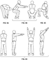
Figure 1A is an illustration of the bending over movement, one of the five movements used to locate micro sites on embodiments of the shirts described herein. -
Figure 1B is an illustration of the squatting movement, one of the five movements used to locate micro sites on embodiments of the shirts described herein. -
Figure 1C is an illustration of the kneeling and twisting movement, one of the five movements used to locate micro sites on embodiments of the shirts described herein. -
Figure 1D is an illustration of the reaching forward and up movement, one of the five movements used to locate micro sites on embodiments of the shirts described herein. -
Figure 1E is an illustration of the big step movement, one of the five movements used to locate micro sites on embodiments of the shirts described herein. -
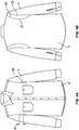
Figure 2A is a front view of an embodiment of a shirt configured to provide a wearer with increased mobility. -
Figure 2B is a rear view of an embodiment of a shirt configured to provide a wearer with increased mobility. -
Figure 3A is an illustration of the embodiment shown inFigure 2 providing a wearer with increased mobility when subjected to a bending over movement. -
Figure 3B is an illustration of the embodiment shown inFigure 2 providing a wearer with increased mobility when subjected to a squatting movement. -
Figure 3C is an illustration of the embodiment shown inFigure 2 providing a wearer with increased mobility when subjected to a kneeling and twisting movement. -
Figure 3D is an illustration of the embodiment shown inFigure 2 providing a wearer with increased mobility when subjected to a reaching forward and up movement. -
Figure 4A is a front view of an embodiment of a shirt configured to provide a wearer with increased mobility. -
Figure 4B is a rear view of an embodiment of a shirt configured to provide a wearer with increased mobility. -
Figure 5A is a front view of an embodiment of a shirt configured to provide a wearer with increased mobility. -
Figure 5B is a rear view of an embodiment of a shirt configured to provide a wearer with increased mobility. -
Figure 6A is an illustration of the embodiment shown inFigure 5 providing a wearer with increased mobility when subjected to a bending over movement. -
Figure 6B is an illustration of the embodiment shown inFigure 5 providing a wearer with increased mobility when subjected to a squatting movement. -
Figure 6C is an illustration of the embodiment shown inFigure 5 providing a wearer with increased mobility when subjected to a kneeling and twisting movement. -
Figure 6D is an illustration of the embodiment shown inFigure 5 providing a wearer with increased mobility when subjected to a reaching forward and up movement. -
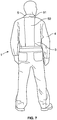
Figure 7 is a rear view of an embodiment of a shirt segment of a coverall configured to provide a wearer with increased mobility. -
Figure 8A is a front view of an embodiment of a shirt configured to provide a wearer with increased mobility. -
Figure 8B is a rear view of an embodiment of a shirt configured to provide a wearer with increased mobility. -
Figure 9A is a front view of an embodiment of a shirt configured to provide a wearer with increased mobility. -
Figure 9B is a rear view of an embodiment of a shirt configured to provide a wearer with increased mobility. - In order to provide a shirt designed for a work uniform that provides a wearer with enhanced mobility, the present inventors have developed a number of embodiments. In some embodiments, the shirt comprises a stretch panel. In other embodiments, the shapes and stitching of various elements of the shirt have been newly configured to produce enhanced mobility.
- In order to determine how to configure a shirt designed for a work uniform so as to provide enhanced mobility, the present inventors used the process for designing garments responsive to the motions of a wearer that is generally described in
U.S. Patent Application No. 14/066,501 . In brief, the process involves identifying common usage patterns and usage positions by the garment wearer, attaching markers used in motion capture photography to the bare skin of a test subject, recording position and movement data of the test subject with a computer system while the test subject repeats the common usage patterns and usage positions, processing the position and movement data to create an opportunity map which identifies stretch and compression areas of the bare skin of the test subject, attaching markers to a standard work garment worn by a test subject, recording garment construction data of the garment worn by the test subject while the test subject repeats the common usage patterns and usage positions, analyzing garment construction data to create a problem map which identifies stretch and compression areas of the garment, creating a mobility map based on the opportunity map and problem map, and using the mobility map to create a shirt design that reduces tension and restriction. - Although key body movements and positions may differ based upon the intended wearer of a shirt (for example a carpenter may have one set of associated body movements while a bricklayer has a different associated set, while a mover has a different associated set), the process was applied over a set of five distinct movements in order to prepare the embodiments of the present invention. As illustrated in
Figures 1A-1E , the five movements are (A) bending over, (B) squatting, (C) kneeling and twisting, (D) reaching forward and up, and (E) big step. These movements were selected because they were believed to be common to a broad array of intended wearers in their respective workplaces. For example, these movements replicate those performed when picking up a box, getting into a truck, and putting an item on a shelf, among other things. - Using the mobility mapping process, a number of micro sites were identified. As defined in
U.S. Patent Application No. 14/066,501 , a "micro site" is generally an identified location on the garment for improved mobility over a predefined range of movements. Using these micro sites, a number of new shirt embodiments that provide significant improvements in a wearer's comfort, performance, and mobility were prepared. - A work shirt 1 comprises a
front panel 2, arear panel 3, a first andsecond sleeve 4, and acollar 5. In contrast to some athletic gear, for instance, a work shirt 1 is generally not form-fitting, i.e. it is not meant to conform to the body. In addition to work shirts, embodiments of the present invention could be incorporated into other types of shirts, such as polo shirts and tee shirts. - In embodiments of the work shirt 1, the
front panel 2 runs from abottom edge 6 up to the collar 5 (centrally located on the garment) and the shoulder seams 7 (on each side of the collar). In some embodiments, i.e. where the shirt 1 may be donned by pulling the shirt on over one's head, thefront panel 2 may comprise a single portion that runs horizontally between afirst side 8 and asecond side 9. In preferred embodiments, and more common to the standard work shirt, thefront panel 2 comprises a right portion and a left portion, which may be removably fastened to one another such as by buttons, snaps, a zipper, or the like. For purposes of this disclosure thefront panel 2 will be described as having afirst side 8 and asecond side 9. This should not be understood as referring to afront panel 2 made up of a single portion, as described above. Rather, thefront panel 2 described herein may comprise a right portion and left portion, with thefirst side 8 of the front panel being located on one of the right and left portions and thesecond side 9 of the front panel being located on the other of the right and left portions. - In a standard work shirt, the
rear panel 3 comprises an upper portion, generally known as a yoke. Embodiments of the shirts 1 described herein may have arear panel 3 that comprises a yoke. However, it was found that the yoke portion of therear panel 3 restricts certain movements. Accordingly, embodiments of the shirts 1 described herein may desirably have the yoke portion of therear panel 3 removed. In these embodiments, therear panel 3 consists of a single portion that runs from abottom edge 10 up to the collar 5 (centrally located on the garment) and the shoulder seams 7 (on each side of the collar). Unless otherwise indication, therear panel 3 should be understood as comprising both the embodiment including a yoke and the embodiment in which the yoke is absent. Therear panel 3 also runs horizontally between afirst side 11 and asecond side 12. - In embodiments of the work shirt 1, the
front panel 2 and therear panel 3 are typically adjoined, such as by sewing, at each of the right and leftshoulders 7. Additionally, thefirst side 8 of the front panel is adjoined, such as by sewing, to thefirst side 11 of the rear panel and thesecond side 9 of the front panel is adjoined to thesecond side 12 of the rear panel. This is, for example, how the front and rear panels of a standard work shirt are adjoined. In other embodiments of the shirts 1 described herein, at least a portion of thefirst side 8 of the front panel is connected to a portion of thefirst side 11 of the rear panel through a stretch panel and at least a portion of thesecond side 9 of the front panel is connected to a portion of thesecond side 12 of the rear panel through a stretch panel. - Similarly, in a standard work shirt, each of the first and
second sleeve portions 4 are adjoined, such as by sewing, to each of thefront panel 2 and therear panel 3. In some embodiments of the shirts 1 described herein, eachsleeve 4 may be adjoined to thefront panel 2 and therear panel 3 in the standard manner. In other embodiments of the shirts 1 described herein, at least a portion of eachsleeve 4 is connected to a portion of therear panel 3 through astretch panel sleeve 4 is connected to a portion of thefront panel 2 through astretch panel seam 60 between thesleeve 4 and therear panel 3 has been reconfigured so as to provide for enhanced mobility. - Embodiments of the shirt 1 may be configured to be capable of withstanding laundering under conditions that are harsher than those used in home laundering processes. For example, in some embodiments, it may be important that the fabric or fabrics that make up the shirt 1 are able to withstand industrial laundering. Many workers in a variety of fields obtain their work wear through a uniform rental program. The garments that are provided by uniform rental programs are washed by a process known as industrial laundering. Industrial laundering must meet a set of standards defined by ISO (the International Organization for Standardization) standards such as ISO 15797 and ISO 30023. For example, in contrast to home laundering processes, which typically take place at about 120° F, industrial laundering takes place at a temperature of at least 150-160° F. Industrial laundering also requires the use of stronger chemicals than those used in a home laundering process. Chemicals used in industrial laundering typically include strong alkali components and strong surfactants. Acids may also be used to bring the pH of a garment to a level that will not irritate the skin. Many industrial laundering processes also employ additional steps that include treatment with agents such as bleaches and/or antichlor compounds. As a result, fabrics that are not configured to withstand the more extreme conditions of industrial laundering may often be destroyed by the process. It is contemplated that embodiments of the shirts 1 may be provided to workers through a uniform rental program. Accordingly, embodiments of the shirts may be configured to be capable of withstanding industrial laundering.
- Embodiments of the shirts 1 of the present invention comprise one or
more stretch panels - The one or
more stretch panels stretch panels 20 preferably have a fabric stretch percentage of at least about 2%, alternatively at least about 5%, alternatively at least about 10%, alternatively at least about 15%, and alternatively at least about 20%. In some embodiments, for example, the stretch panels may have a fabric stretch percentage between about 20% and about 30%. The stretchability may also be defined according to the direction in which stretching forces are applied. 2-way stretch fabrics stretch in one direction (e.g. either lengthwise or crosswise), while 4-way stretch fabrics stretch in both directions (lengthwise and crosswise). Embodiments of thestretch panel stretch panel 20 comprises a 4-way stretch material, such as a 4-way stretch material having a fabric stretch percentage in both directions of at least about 2%, alternatively at least about 5%, alternatively at least about 10%, alternatively at least about 15%, and alternatively at least about 20%. In some embodiments, for example, the stretch panels may have a fabric stretch percentage that is between about 20% and about 30% in both directions. - For example, in some embodiments, the stretchable fabric may comprise a blend of polyester, cotton, and spandex. The blend of polyester, cotton, and spandex may, for example, be specially configured to withstand industrial laundering. In view of the above disclosure, it is believed that a person of ordinary skill in the art would understand, and be able to select from, a variety of stretchable fabrics that could be used in the
stretch panels - The one or
more stretch panels stretch panel - In some embodiments, the one or
more stretch panels stretch panel 20 so that the stretch panel is substantially concealed when not being subjected to a movement that causes it to stretch. The flaps are desirably made of the base material of the shirt 1 and may provide an additional protective element to the wearer in the area of thestretch panel 20. - In some embodiments, the one or
more stretch panels more stretch panels more stretch panels more stretch panels - Additionally, although the invention is described herein as being directed to a stand-alone shirt, it should be understood that the shirt described herein may also be a segment of a full body uniform, such as a coverall. While some of the general components of a coverall top segment may take on a slightly different form from a stand-alone work shirt, the mobility enhancing features of any of the stand-alone shirts described herein could be equally applicable to the top segment of a coverall, as would be understood by a person of ordinary skill in the art. Accordingly, the term shirt, as used herein, is not limited to stand-alone shirts, but rather should be understood to include the shirt-portion of a coverall, for example.
- An embodiment of the present invention is illustrated in
Figures 2A and 2B . The embodiment illustrated inFigures 2A and 2B comprises astretch panel 20 located on therear panel 3 of the shirt 1. Thestretch panel 20 comprises a plurality ofprotrusions 21 that extend from acentral point 22. In some embodiments, the angle α between each of the plurality of protrusions 21 (i.e. the angle formed by two adjacent protrusions about the central point 22) is between about 90 degrees and about 150 degrees, alternatively between about 95 degrees and about 145 degrees, alternatively between about 100 degrees and about 140 degrees, alternatively between about 110 degrees and about 130 degrees, alternatively between about 115 degrees and about 126 degrees, alternatively between about 118 and about 123 degrees. - In some embodiments, the
stretch panel 20 comprises afirst protrusion 23 extending vertically toward thecollar 5 of the shirt, asecond protrusion 24 extending diagonally downward and toward afirst side 11 of therear panel 3, and athird protrusion 25 extending diagonally downward and toward asecond side 12 of the rear panel. - The angle formed by the
first protrusion 23 and thesecond protrusion 24 is preferably between about 90 degrees and about 150 degrees, more preferably between about 95 degrees and about 145 degrees, more preferably between about 100 degrees and about 140 degrees, more preferably between about 110 degrees and about 130 degrees, more preferably between about 115 degrees and about 126 degrees. In some embodiments, the angle formed by thefirst protrusion 23 and thesecond protrusion 24 is between about 118 and about 123 degrees. - The angle formed by the
first protrusion 23 and thethird protrusion 25 is preferably between about 90 degrees and about 150 degrees, more preferably between about 95 degrees and about 145 degrees, more preferably between about 100 degrees and about 140 degrees, more preferably between about 110 degrees and about 130 degrees, more preferably between about 115 degrees and about 126 degrees. In some embodiments, the angle formed by thefirst protrusion 23 and thethird protrusion 25 is between about 118 and about 123 degrees. - The angle formed by the
second protrusion 24 and thethird protrusion 25 is preferably between about 90 degrees and about 150 degrees, more preferably between about 95 degrees and about 145 degrees, more preferably between about 100 degrees and about 140 degrees, more preferably between about 110 degrees and about 130 degrees, more preferably between about 115 degrees and about 126 degrees. In some embodiments, the angle formed by thesecond protrusion 24 and thethird protrusion 25 is between about 118 and about 123 degrees. - In some embodiments, the
central point 22 of thestretch panel 20 is located substantially central to therear panel 3 of shirt between thefirst side 11 and thesecond side 12. By substantially central it is meant within 3 inches from the center point between thefirst side 11 and thesecond side 12 of therear panel 3. Preferably, thecentral point 22 of thestretch panel 20 is located within 2 inches from the center point between thefirst side 11 and thesecond side 12 of therear panel 3. Preferably, thecentral point 22 of thestretch panel 20 is located within 1 inch from the center point between thefirst side 11 and thesecond side 12 of therear panel 3. - In some embodiments, the
central point 22 of thestretch panel 20 is located between about four and about twenty-five inches below the seam that adjoins therear panel 3 to thecollar 5, more preferably between about five and about eighteen inches below the seam that adjoins the rear panel to the collar, more preferably between about six and about fifteen inches below the seam that adjoins the rear panel to the collar, more preferably between about seven and about fourteen, alternatively between about eight and about thirteen inches below the seam that adjoins the rear panel to the collar. - In some embodiments, each of the plurality of
protrusions 21 converges, or narrows in width, so as to form atip 26 at the end of the protrusion opposite thecentral point 22. The width of eachprotrusion 21 may be selected, depending on the size and intended usage of the shirt 1, to provide the desired amount of stretchability to the shirt while at the same time minimizing the dimensions of the stretch panel 20 (and accordingly the amount of stretch material used in the garment). In some embodiments, eachprotrusion 21 has a maximum width, i.e. the width at the widest portion of the protrusion, of less than ten inches, alternatively less than seven inches, alternatively less than five inches, alternatively less than three inches. In some embodiments, each protrusion has a maximum width between about 0.5 inches and about five inches, alternatively between about 0.5 inches and about four inches, alternatively between about 0.5 inches and about three inches. - The length of each
protrusion 21 may also be selected, depending on the size and intended usage of the shirt 1, to provide the desired amount of stretchability to the shirt while at the same time minimizing the dimensions of the stretch panel 20 (and accordingly the amount of stretch material used in the garment). In some embodiments, eachprotrusion 21 has a length between about 5 and about 25 inches, alternatively between about 6 and about 20 inches, alternatively between about 7 and about 16 inches, alternatively between about 8 and about 15 inches. - The stretching of an embodiment such as described above in response to the common motions applied to the mobility mapping process is shown in
Figures 3A to 3D . The embodiment illustrated comprises a stretch panel located on the rear panel of the shirt and having a first protrusion, a second protrusion, and a third protrusion radiating from a central point, as described above. As a wearer performs the range of motions, the stretch panel provides for stretching of the rear panel of the shirt at the identified micro sites in order to provide significant improvements in a wearer's comfort, performance, and mobility. - Another embodiment of the present invention is illustrated in
Figures 4A and 4B . The embodiment illustrated inFigures 4A and 4B comprises afirst stretch panel 30 that spans the connection between thefirst sleeve portion 4 and therear panel 3 and a second stretch panel that spans the connection between the second sleeve portion and the rear panel. Accordingly, eachstretch panel 30 is adjoined, such as by sewing, on afirst side 31 to therear panel 3 and on a second (and opposite)side 32 to thesleeve 4. As such, thesleeve 4 is not directly adjoined to therear panel 3 of the shirt. Rather thesleeve 4 is connected to thestretch panel 30, which is connected to therear panel 3 of the shirt. In some embodiments, such as is illustrated inFigure 4B , thestretch panel 30 curves around thesleeve 4, so as to have a convexfirst side 31 and a concavesecond side 32. - The maximum width between the
first side 31 of each stretch panel and thesecond side 32 of each stretch panel may be selected, depending on the size and intended usage of the shirt 1, to provide the desired amount of stretchability to the shirt while at the same time minimizing the dimensions of the stretch panel 30 (and accordingly the amount of stretch material used in the garment). In some embodiments, eachstretch panel 30 has a maximum width, i.e. the width at the widest portion between thefirst side 31 and thesecond side 32, of less than eight inches, alternatively less than seven inches, alternatively less than six inches, alternatively less than five inches, alternatively less than four inches. In some embodiments, each stretch panel has a maximum width between about 0.5 and about five inches, alternatively between about 0.5 and about four inches, alternatively between about one and about four inches. - In some embodiments, the
stretch panel 30 also extends below thesleeve 4 and at least partially upward between the sleeve and thefront panel 2 of the shirt. In the embodiment illustrated inFigure 4A , for example, eachstretch panel 30 partially spans the connection between thesleeve 4 and thefront panel 2. In some embodiments, thestretch panel 30 spans the connection between thesleeve portion 4 and thefront panel 2 for a distance d that is between about 0.5 inches and about 10 inches, alternatively between about 1 inch and about 8 inches, alternatively between about 1 inch and about 6 inches, as determined by measuring the length of the seam adjoining thesecond side 32 of the stretch panel to thesleeve 4, starting at the point of the seam that is vertically aligned with the line formed by the side seam of the shirt that connects thefront panel 2 with therear panel 3. - The stretching of an embodiment such as described above in response to the common motions applied to the mobility mapping process is not illustrated. However, as a wearer performs the range of motions, the
stretch panel 30 provides for stretching of the shirt 1 at the identified micro sites in order to provide significant improvements in a wearer's comfort, performance, and mobility. - Another embodiment of the present invention is illustrated in
Figures 5A and 5B . The embodiment illustrated inFigures 5A and 5B also comprises afirst stretch panel 40 that spans the connection between thefirst sleeve portion 4 and therear panel 3 and a second stretch panel that spans the connection between the second sleeve portion and the rear panel. However, in contrast to the embodiment described above, each of thestretch panels 40 of the embodiment illustrated inFigures 5A and 5B also span the connection between thesleeve portion 4 and thefront panel 2. Accordingly, eachstretch panel 40 is adjoined, such as by sewing, on afirst side 41 to the front panel and on a second (and opposite)side 42 to the sleeve. As such, thesleeve 4 is not directly adjoined to thefront panel 2 of the shirt. Rather thesleeve 4 is connected to thestretch panel 40, which is connected to thefront panel 2 of the shirt. In some embodiments, such as is illustrated inFigure 5A , thestretch panel 40 curves around thesleeve 4, so as to have a convexfirst side 41 and a concavesecond side 42. - In some embodiments, the
stretch panel 40 also adjoins therear panel 3 from at or near the bottom edge of therear panel 10 up to theshoulder 7. Thestretch panel 40 may also adjoin thefront panel 2 from at or near the bottom edge of thefront panel 6 to theshoulder 7. Accordingly, in some embodiments, thefirst side 8 of thefront panel 2 is not directly adjoined to thefirst side 11 of therear panel 3 and thesecond side 9 of the front panel is not directly adjoined to thesecond side 12 of the rear panel. Rather, thefirst side 8 of the front panel is connected to thestretch panel 40, which is connected to thefirst side 11 of the rear panel and thesecond side 9 of the front panel is connected to thestretch panel 40, which is connected to thesecond side 12 of the rear panel. - In some embodiments, such as the embodiment illustrated in
Figure 5B , the seam adjoining thestretch panel 40 to therear panel 3 from at or near the bottom edge of therear panel 10 to theshoulder 7 forms an "S"-like shape. In other words, the seam panel curves from at or near the side of therear panel 3 inward toward the center of the rear panel, then back outward toward the side of the rear panel, and finally back inward toward the center of the rear panel. The widest portions of thestretch panel 40 are preferably located at the portions identified byreference numbers rear panel 3 may vary depending on the size of the shirt 1 and the intended usage of the shirt. The curved seam provides a wearer with additional mobility by flexing straight when stretched. - Additionally, in some embodiments, such as the embodiment illustrated in
Figure 5A , the seam adjoining thestretch panel 40 to thefront panel 2 from at or near the bottom edge of thefront panel 6 to theshoulder 7 forms an "S"-like shape. In other words, the seam curves from at or near the side of thefront panel 2 inward toward the center of the front panel, then back outward toward the side of the front panel, and finally back inward toward the center of the front panel. The widest portions of thestretch panel 40 are preferably located at the portions identified byreference numbers front panel 2 may vary depending on the size of the shirt 1 and the intended usage of the shirt. The curved seam provides a wearer with additional mobility by flexing straight when stretched. - The stretching of an embodiment such as described above in response to the common motions applied to the mobility mapping process is shown in
Figures 6A through 6D . The embodiment illustrated comprises astretch panel 40 that spans the connection between thesleeve portion 4 and therear panel 3 and the connection between the sleeve portion and thefront panel 2. Thestretch panel 40 also adjoins both therear panel 3 and thefront panel 2 from the bottom edges of theshirt shoulder 7. Both the seam adjoining thestretch panel 40 to therear panel 3 and the seam adjoining thestretch panel 40 to thefront panel 2 form an "S"-like shape. As a wearer performs the range of motions, thestretch panel 40 provides for stretching of the shirt at the identified micro sites in order to provide significant improvements in a wearer's comfort, performance, and mobility. - In some alternative embodiments, the
stretch panel 40 shown inFigures 5 and6 may be replaced with a conventional fabric. In these embodiments, the panel around the sleeves and along the sides of the shirt provides a wearer with enhanced mobility even without the use of a material having an increased degree of stretchability over the material used in the remainder of the shirt 1. - Another embodiment of the present invention is illustrated in
Figure 7 . The embodiment inFigure 7 has been illustrated as the shirt component of a coverall garment. Although not so limited, this embodiment is particularly desirable for use in a shirt 1 that is a component of a coverall. For example, in addition to increasing mobility across the described range of movements, this embodiment also makes it easier for a wearer to pull a coverall over his or her shoulders when donning and/or doffing the coverall garment. The embodiment illustrated inFigure 7 comprises astretch panel 50 located onrear portion 3 of the shirt segment 1 of a coverall and spanning the height of the rear portion between the waist and thecollar 5. Thestretch panel 50 is located substantially centrally along therear portion 3 of the shirt segment 1 of the coverall. In some embodiments, thestretch panel 50 may also extend into thecollar portion 5 of the coverall. Thecollar 5 may also comprise a v-shapednotch 51 that creates extra room for donning and/or doffing of the coverall garment. - The width of the
stretch panel 50 may be selected, depending on the size and intended usage of the coverall, to provide the desired amount of stretchability to the shirt segment 1 while at the same time minimizing the dimensions of the stretch panel (and accordingly the amount of stretch material used in the garment). In some embodiments, thestretch panel 50 has a width between about one and about twenty inches, alternatively between about five inches and about fifteen inches. - In other embodiments of the present invention, the shaping of the various portions of the shirt 1 and the manner in which the portions of the shirt are connected together, and specifically the connection between each of the
sleeves 4 and therear panel 3 of the shirt may be specially configured in order to provide enhanced mobility. - For example, another embodiment of the present invention is illustrated in
Figures 8A and 8B . The embodiment illustrated inFigures 8A and 8B comprises an "extended rear panel portion" identified byreference 61. In a standard shirt 1, the seam that adjoins a sleeve to a rear panel has a radius of curvature facing away from the rear panel and toward the sleeve. In other words, the seam has a convex side that extends toward the center of the rear panel. This standard seam is indicated inFigure 8B , for example, by the dashed line identified byreference 70. In contrast, theseam 60 of this embodiment has a radius of curvature facing toward therear panel 3 and away from thesleeve 4, such that the seam has a convex side that extends away from the center of the rear panel. - In this way, the
rear panel 3 has a greater width between itsfirst side 11 and itssecond side 12 in the area around thesleeve 4, which may be called an extendedrear panel portion 61. As a wearer performs the range of motions, the extendedrear panel portion 61 provides additional fabric at the identified micro sites in order to provide significant improvements in a wearer's comfort, performance, and mobility. When viewed from the front, however, the shirt 1 may have the appearance of a standard work shirt. - Alternatively, the embodiment illustrated in
Figures 9A and 9B comprises an "extended sleeve portion" identified byreference 62. In contrast to a standard shirt, the extended sleeve portion of the embodiment illustrated inFigures 9A and 9B has aseam 60 that adjoins thesleeve 4 to therear panel 3 that traverses the rear panel of the shirt from apoint 63 at the first side of therear panel 11 up the apoint 64 at thecollar 5. Thepoint 63 at the first side of therear panel 12 may be a distance d' below the lowest point at which thesleeve 4 adjoins thefront panel 2 of the shirt. This distance d' may be, for example, between about two inches and about fifteen inches, alternatively between about three inches and about twelve inches, alternatively between about four inches and about ten inches, alternatively between about six inches and about eight inches. - In some embodiments, the
seam 60 connecting thesleeve 4 to thefirst side 11 of therear panel 3 curves upward from thepoint 63 at the first side of the rear panel described above to apoint 65 that is substantially central between thefirst side 11 of the rear panel and thesecond side 12 of the rear panel, at whichpoint 65 theseam 60 extends vertically to thepoint 64 at thecollar 5. As such, in some embodiments, theseam 60 connecting thesleeve 4 to thefirst side 11 of the rear panel and theseam 60 connecting the sleeve to thesecond side 12 of the rear panel overlap at alocation 65 substantially central between thefirst side 11 of the rear panel and thesecond side 12 of the rear panel. - In this way, each of the
sleeves 4 may extend well into the region of the shirt 1 that is normally considered to be therear panel 3, to produce anextended sleeve portion 62. As a wearer performs the range of motions, theextended sleeve portion 62 provides additional fabric at the identified micro sites in order to provide significant improvements in a wearer's comfort, performance, and mobility. When viewed from the front, however, the shirt 1 may have the appearance of a standard work shirt. - It should be understood that none of the shirts 1 described and/or claimed herein are in any way limited by the process in which they were designed or produced. In other words, although the shirts 1 described and/or claimed herein were designed by the mobility mapping process described above, that process should in no way be considered a required component or element of the shirts themselves.
- It can be seen that the described embodiments provide unique and novel shirts that have a number of advantages over those in the art. While there is shown and described herein certain specific structures embodying the invention, it will be manifest to those skilled in the art that various modifications and rearrangements of the parts may be made. The invention is defined by the appended claims.
Claims (8)
- A shirt (1) configured for enhanced mobility, comprising:a. a front panel (2), a rear panel (3), a first sleeve (4) and a second sleeve (4), a collar (5);b. a stretch panel (20) located on the rear panel (3) and comprises three protrusions (23, 24, 25) that extend from a central point (22), the three protrusions (23, 24, 25) including:a first protrusion (23) extending vertically toward the collar (5) of the shirt (1), a second protrusion (24) extending diagonally downward and toward a first side (11) of the rear panel (3), anda third protrusion (25) extending diagonally downward and toward a second side (12) of the rear panel (3);characterized in that
each protrusion (23, 24, 25) converges to a tip (26) at the end opposite the central point (22); and
in that the stretch panel (20) provides a wearer with enhanced mobility when performing one or more of the following motions: (a) bending over, (b) squatting, (c) kneeling and twisting, (d) reaching forward and up, and (e) big step. - The shirt (1) of claim 1, in which the stretch panel (20) has a four-way stretch of at least about 15%, preferably of at least about 20%.
- The shirt (1) of claim 1 or 2, in which the angle between each of the protrusions (23, 24, 25) is between about 110 and about 130 degrees.
- The shirt (1) of any one of claims 1 to 3, in which the central point (22) is located substantially centrally between the first side (11) of the rear panel (3) and the second side (12) of the rear panel (3) and between about 203.2 mm (eight inches) and about 330.2 (thirteen inches) below the collar (5).
- The shirt (1) of any one of claims 1 to 4, in which each protrusion (23, 24, 25) has a maximum width of less than 76.2 mm (three inches).
- The shirt (1) of any one of claims 1 to 5, wherein the stretch panel (20) has an air permeability that is greater than the air permeability of the base material of the shirt (1).
- The shirt (1) of any one of claims 1 to 6, in which the shirt (1) is configured to withstand industrial laundering.
- The shirt (1) of any one of claims 1 to 7, wherein the shirt (1) is a segment of a coverall.
Priority Applications (1)
| Application Number | Priority Date | Filing Date | Title |
|---|---|---|---|
| PL15826389T PL3174412T3 (en) | 2014-07-30 | 2015-07-30 | Shirts configured for enhancing worker mobility |
Applications Claiming Priority (3)
| Application Number | Priority Date | Filing Date | Title |
|---|---|---|---|
| US201462031005P | 2014-07-30 | 2014-07-30 | |
| US14/645,508 US10085490B2 (en) | 2014-07-30 | 2015-03-12 | Shirts configured for enhancing worker mobility |
| PCT/US2015/042832 WO2016019109A1 (en) | 2014-07-30 | 2015-07-30 | Shirts configured for enhancing worker mobility |
Publications (3)
| Publication Number | Publication Date |
|---|---|
| EP3174412A1 EP3174412A1 (en) | 2017-06-07 |
| EP3174412A4 EP3174412A4 (en) | 2018-01-10 |
| EP3174412B1 true EP3174412B1 (en) | 2020-06-24 |
Family
ID=55178663
Family Applications (1)
| Application Number | Title | Priority Date | Filing Date |
|---|---|---|---|
| EP15826389.7A Active EP3174412B1 (en) | 2014-07-30 | 2015-07-30 | Shirts configured for enhancing worker mobility |
Country Status (11)
| Country | Link |
|---|---|
| US (3) | US10085490B2 (en) |
| EP (1) | EP3174412B1 (en) |
| JP (1) | JP6727188B2 (en) |
| CN (1) | CN107072323B (en) |
| CA (1) | CA2955200C (en) |
| DK (1) | DK3174412T3 (en) |
| ES (1) | ES2815648T3 (en) |
| HU (1) | HUE050850T2 (en) |
| PL (1) | PL3174412T3 (en) |
| PT (1) | PT3174412T (en) |
| WO (1) | WO2016019109A1 (en) |
Families Citing this family (13)
| Publication number | Priority date | Publication date | Assignee | Title |
|---|---|---|---|---|
| US10085490B2 (en) * | 2014-07-30 | 2018-10-02 | Vf Imagewear, Inc. | Shirts configured for enhancing worker mobility |
| USD780407S1 (en) * | 2015-10-06 | 2017-03-07 | Mazsport Garment Manufacturing Inc. | Paint suit |
| US10701996B2 (en) * | 2016-11-08 | 2020-07-07 | Vf Imagewear, Inc. | Garment having mobility-enhancing arm pleat |
| USD838937S1 (en) * | 2016-11-29 | 2019-01-29 | Pvh Corp. | Shirt |
| US10918512B2 (en) * | 2016-12-06 | 2021-02-16 | James Earl Jackson | Gird compression tensioning garment with cervical collar |
| EP3687326A4 (en) * | 2017-09-26 | 2021-07-07 | Fortiac Corporation | Non-stretch garment having knit stretch panels |
| WO2020065971A1 (en) * | 2018-09-28 | 2020-04-02 | 株式会社アシックス | Shirt and pants |
| USD930953S1 (en) * | 2019-04-18 | 2021-09-21 | 612465 Ontario Limited | Garment with flexible panels |
| ES1242679Y (en) * | 2020-01-16 | 2020-08-19 | Poleka Shirt Project Sl | CLOTHING FOR THE UPPER BODY |
| USD941556S1 (en) * | 2020-07-06 | 2022-01-25 | New Normal Work Wear LLC | Jumpsuit |
| US12557855B2 (en) * | 2022-06-28 | 2026-02-24 | Acushnet Company | Garment including stretch panels |
| JP2026509426A (en) | 2023-03-08 | 2026-03-19 | シーメンス メディカル ソリューションズ ユーエスエー インコーポレイテッド | Continuous cooling system for diagnostic medical imaging devices |
| JP7686208B1 (en) | 2024-04-30 | 2025-06-02 | 住商モンブラン株式会社 | jacket |
Family Cites Families (53)
| Publication number | Priority date | Publication date | Assignee | Title |
|---|---|---|---|---|
| US3086214A (en) | 1960-04-07 | 1963-04-23 | Lash Seymour | Self-adjusting stretch coverall |
| US3137860A (en) * | 1961-07-25 | 1964-06-23 | Freezer & Son Inc J | Sport shirts |
| US5052053A (en) | 1988-12-05 | 1991-10-01 | O'neill, Inc. | Garment for aquatic activities having increased elasticity and method of making same |
| US4890337A (en) | 1988-12-27 | 1990-01-02 | Bert Greenberg | Pants-like garment incorporating a stretchable construction |
| US4937883A (en) | 1989-03-10 | 1990-07-03 | Shirai Todd T | Athletic shirt |
| CA1320313C (en) | 1989-07-05 | 1993-07-20 | Jean-Pierre Audet | Stretchable garment |
| US5072454A (en) | 1990-08-15 | 1991-12-17 | Globe Manufacturing Company | Garments with appendage portions having extensible flexible joints |
| JP2568362B2 (en) | 1992-11-24 | 1997-01-08 | 株式会社ワコール | clothes |
| US5477595A (en) | 1994-02-14 | 1995-12-26 | Burlington Industries, Inc. | Knitted fabric construction for an industrially launderable soft hand knitted garment |
| JP2898225B2 (en) | 1995-07-20 | 1999-05-31 | キシ株式会社 | Clothes with lining function |
| US5737773A (en) | 1997-02-20 | 1998-04-14 | Dicker; Timothy P. | Aerobic exercise garment |
| JP3012819B2 (en) | 1997-04-01 | 2000-02-28 | 株式会社ワコール | Lower limb protection clothing |
| US5901374A (en) | 1998-03-19 | 1999-05-11 | Hodgman, Inc. | Flexible knee wader |
| US6076187A (en) | 1998-05-15 | 2000-06-20 | Wallerstein; Robert | Elacticized form fitting shirt |
| US6212686B1 (en) | 1998-10-14 | 2001-04-10 | Arthur A. Krause | Expandable shirt collar |
| US7146647B2 (en) | 1998-10-14 | 2006-12-12 | Krause Arthur A | Expandable, no-shrink shirt collar |
| US7074204B2 (en) | 1999-04-21 | 2006-07-11 | Wacoal Corp. | Garment |
| US6311333B1 (en) | 1999-08-05 | 2001-11-06 | Union Underwear Company, Inc. | Invisible stretch garment |
| GB9929867D0 (en) | 1999-12-17 | 2000-02-09 | Speedo International Limited | Articles of clothing |
| US6279161B1 (en) | 2000-01-19 | 2001-08-28 | Steven E. Johnston | Biographics: apparel that has moving graphics and patterns |
| TW475887B (en) | 2000-04-20 | 2002-02-11 | Wacoal Corp | Leg portions supporting wear |
| TWI294939B (en) | 2002-03-11 | 2008-03-21 | Dow Global Technologies Inc | Stretch fabrics with improved chemical resistance and durability |
| US6874337B2 (en) | 2002-06-05 | 2005-04-05 | Mizuno Corporation | Underpant garment |
| US7941871B1 (en) | 2003-08-18 | 2011-05-17 | Joey Jorgensen | Garment with stretchable section and related methods |
| US7310824B2 (en) | 2004-09-08 | 2007-12-25 | Simms Fishing Products Llc | Garment with hydrophobic forearms |
| WO2006080095A1 (en) | 2005-01-28 | 2006-08-03 | Utax Co., Ltd. | Clothes with crotch part |
| JP4431616B2 (en) | 2005-07-08 | 2010-03-17 | 株式会社アシックス | Wear |
| FR2889033B1 (en) | 2005-07-29 | 2007-12-28 | Salomon Sa | CLOTHED GARMENT |
| DE602005018118D1 (en) | 2005-09-13 | 2010-01-14 | Alpinestars Res Srl | SPORTSWEAR WITH MORE COMFORT |
| US7546853B2 (en) | 2006-05-30 | 2009-06-16 | Mmi-Ipco, Llc | Advanced engineered garment |
| CN101351129B (en) | 2006-12-26 | 2010-04-21 | 华哥尔株式会社 | Sportswear |
| US10863783B2 (en) * | 2007-04-16 | 2020-12-15 | Kimberly-Clark Worldwide, Inc. | Protective apparel with angled stretch panel |
| US9125442B2 (en) * | 2007-05-23 | 2015-09-08 | Intelliskin Usa, Llc | Sensory motor stimulation garment and method |
| US9119707B2 (en) * | 2007-05-23 | 2015-09-01 | Intelliskin Usa, Llc | Sensory motor stimulation garment and method |
| US9061477B2 (en) | 2007-12-13 | 2015-06-23 | Kitaru Innovations Inc. | Method and apparatus for making, shipping and erecting boxes |
| US20110209263A1 (en) | 2008-10-30 | 2011-09-01 | Toray Industries, Inc. | Garment |
| US8533864B1 (en) | 2009-03-26 | 2013-09-17 | Kris A. Kostrzewski | Stabilizing garment system |
| US9259036B2 (en) | 2009-10-30 | 2016-02-16 | Outlier Incorporated | Pivot sleeve |
| JP5150681B2 (en) | 2010-06-22 | 2013-02-20 | 帝人フロンティア株式会社 | Golf shirt |
| CN103140146A (en) | 2010-09-30 | 2013-06-05 | 绿安全股份有限公司 | Trousers, work trousers and overalls |
| US8728636B2 (en) | 2010-12-13 | 2014-05-20 | Southwall Technologies Inc. | Insulating glass unit with crack-resistant low-emissivity suspended film |
| US8656515B2 (en) | 2011-01-11 | 2014-02-25 | Reebok International Limited | Performance apparel with flexible portion |
| US20120233738A1 (en) | 2011-03-16 | 2012-09-20 | Blauer Manufacturing Company, Inc. | Shirt Sleeve Construction |
| WO2012168782A1 (en) * | 2011-06-10 | 2012-12-13 | PUNI, Vishal | Shoulder stabilization shirt |
| US20130160181A1 (en) | 2011-12-22 | 2013-06-27 | Rebecca Catherine Mohr | Garment |
| EP2797452B1 (en) * | 2011-12-30 | 2017-07-19 | Opedix, LLC | Shirts and shorts having elastic and non-stretch portions and bands to provide hip and posture support |
| US9624608B2 (en) | 2012-02-17 | 2017-04-18 | Nike, Inc. | Architecturally reinforced denim |
| US20130212779A1 (en) | 2012-02-22 | 2013-08-22 | Haggar Clothing Co. | Waistband And Pocket Expansion System For Garments |
| US20130260628A1 (en) * | 2012-03-30 | 2013-10-03 | II William Thomas Woods | Multi-Direction Stretch Fabric |
| US20130305425A1 (en) | 2012-05-15 | 2013-11-21 | Rock Fit, Llc | Supportive garments |
| US20140336556A1 (en) * | 2013-05-13 | 2014-11-13 | TheraChic LLC | Posture support garment |
| US9655389B2 (en) * | 2014-01-14 | 2017-05-23 | Under Armour, Inc. | Article of apparel |
| US10085490B2 (en) * | 2014-07-30 | 2018-10-02 | Vf Imagewear, Inc. | Shirts configured for enhancing worker mobility |
-
2015
- 2015-03-12 US US14/645,508 patent/US10085490B2/en active Active
- 2015-07-30 DK DK15826389.7T patent/DK3174412T3/en active
- 2015-07-30 PL PL15826389T patent/PL3174412T3/en unknown
- 2015-07-30 CN CN201580053124.9A patent/CN107072323B/en active Active
- 2015-07-30 PT PT158263897T patent/PT3174412T/en unknown
- 2015-07-30 HU HUE15826389A patent/HUE050850T2/en unknown
- 2015-07-30 JP JP2017504168A patent/JP6727188B2/en active Active
- 2015-07-30 EP EP15826389.7A patent/EP3174412B1/en active Active
- 2015-07-30 WO PCT/US2015/042832 patent/WO2016019109A1/en not_active Ceased
- 2015-07-30 ES ES15826389T patent/ES2815648T3/en active Active
- 2015-07-30 CA CA2955200A patent/CA2955200C/en active Active
-
2018
- 2018-10-01 US US16/148,758 patent/US11051559B2/en active Active
-
2021
- 2021-06-04 US US17/339,589 patent/US12207690B2/en active Active
Non-Patent Citations (1)
| Title |
|---|
| None * |
Also Published As
| Publication number | Publication date |
|---|---|
| CN107072323A (en) | 2017-08-18 |
| EP3174412A4 (en) | 2018-01-10 |
| US12207690B2 (en) | 2025-01-28 |
| US11051559B2 (en) | 2021-07-06 |
| JP2017522463A (en) | 2017-08-10 |
| CA2955200C (en) | 2022-09-20 |
| PL3174412T3 (en) | 2020-12-14 |
| DK3174412T3 (en) | 2020-08-31 |
| US20210289847A1 (en) | 2021-09-23 |
| US10085490B2 (en) | 2018-10-02 |
| US20190029327A1 (en) | 2019-01-31 |
| WO2016019109A1 (en) | 2016-02-04 |
| HUE050850T2 (en) | 2021-01-28 |
| EP3174412A1 (en) | 2017-06-07 |
| ES2815648T3 (en) | 2021-03-30 |
| CN107072323B (en) | 2019-03-08 |
| CA2955200A1 (en) | 2016-02-04 |
| PT3174412T (en) | 2020-09-08 |
| JP6727188B2 (en) | 2020-07-22 |
| US20160029702A1 (en) | 2016-02-04 |
Similar Documents
| Publication | Publication Date | Title |
|---|---|---|
| US12207690B2 (en) | Shirts configured for enhancing worker mobility | |
| US12610992B2 (en) | Pants configured for enhancing worker mobility | |
| US11274383B2 (en) | Engineered knit with multi-density knit zone | |
| WO2017106667A1 (en) | Sleeve gusset for an apparel item | |
| EP4099860B1 (en) | Upper body garment with enhanced mobility portions | |
| US20200268059A1 (en) | Non-Stretch Garment Having Knit Stretch Panels | |
| CA3011574C (en) | Undergarment for children | |
| HK1236764B (en) | Shirts configured for enhancing worker mobility | |
| HK1236764A1 (en) | Shirts configured for enhancing worker mobility | |
| HK1236766A1 (en) | Pants configured for enhancing worker mobility | |
| HK1236766B (en) | Pants configured for enhancing worker mobility | |
| JPH11189906A (en) | Cutting of cloth for production of elastic dress | |
| US20030213048A1 (en) | Customizable gloves |
Legal Events
| Date | Code | Title | Description |
|---|---|---|---|
| STAA | Information on the status of an ep patent application or granted ep patent |
Free format text: STATUS: THE INTERNATIONAL PUBLICATION HAS BEEN MADE |
|
| 17P | Request for examination filed |
Effective date: 20170126 |
|
| AK | Designated contracting states |
Kind code of ref document: A1 Designated state(s): AL AT BE BG CH CY CZ DE DK EE ES FI FR GB GR HR HU IE IS IT LI LT LU LV MC MK MT NL NO PL PT RO RS SE SI SK SM TR |
|
| AX | Request for extension of the european patent |
Extension state: BA ME |
|
| PUAI | Public reference made under article 153(3) epc to a published international application that has entered the european phase |
Free format text: ORIGINAL CODE: 0009012 |
|
| STAA | Information on the status of an ep patent application or granted ep patent |
Free format text: STATUS: REQUEST FOR EXAMINATION WAS MADE |
|
| DAV | Request for validation of the european patent (deleted) | ||
| DAX | Request for extension of the european patent (deleted) | ||
| REG | Reference to a national code |
Ref country code: DE Ref legal event code: R079 Ref document number: 602015054824 Country of ref document: DE Free format text: PREVIOUS MAIN CLASS: A41B0001000000 Ipc: A41B0001080000 |
|
| A4 | Supplementary search report drawn up and despatched |
Effective date: 20171212 |
|
| RIC1 | Information provided on ipc code assigned before grant |
Ipc: A41B 1/08 20060101AFI20171206BHEP Ipc: A41D 13/02 20060101ALI20171206BHEP Ipc: A41D 13/00 20060101ALI20171206BHEP Ipc: A41D 27/00 20060101ALI20171206BHEP |
|
| REG | Reference to a national code |
Ref country code: HK Ref legal event code: DE Ref document number: 1236764 Country of ref document: HK |
|
| STAA | Information on the status of an ep patent application or granted ep patent |
Free format text: STATUS: EXAMINATION IS IN PROGRESS |
|
| 17Q | First examination report despatched |
Effective date: 20181023 |
|
| GRAP | Despatch of communication of intention to grant a patent |
Free format text: ORIGINAL CODE: EPIDOSNIGR1 |
|
| STAA | Information on the status of an ep patent application or granted ep patent |
Free format text: STATUS: GRANT OF PATENT IS INTENDED |
|
| INTG | Intention to grant announced |
Effective date: 20200108 |
|
| GRAS | Grant fee paid |
Free format text: ORIGINAL CODE: EPIDOSNIGR3 |
|
| GRAA | (expected) grant |
Free format text: ORIGINAL CODE: 0009210 |
|
| STAA | Information on the status of an ep patent application or granted ep patent |
Free format text: STATUS: THE PATENT HAS BEEN GRANTED |
|
| AK | Designated contracting states |
Kind code of ref document: B1 Designated state(s): AL AT BE BG CH CY CZ DE DK EE ES FI FR GB GR HR HU IE IS IT LI LT LU LV MC MK MT NL NO PL PT RO RS SE SI SK SM TR |
|
| REG | Reference to a national code |
Ref country code: GB Ref legal event code: FG4D |
|
| REG | Reference to a national code |
Ref country code: CH Ref legal event code: EP |
|
| REG | Reference to a national code |
Ref country code: AT Ref legal event code: REF Ref document number: 1282994 Country of ref document: AT Kind code of ref document: T Effective date: 20200715 |
|
| REG | Reference to a national code |
Ref country code: DE Ref legal event code: R096 Ref document number: 602015054824 Country of ref document: DE |
|
| REG | Reference to a national code |
Ref country code: IE Ref legal event code: FG4D |
|
| REG | Reference to a national code |
Ref country code: DK Ref legal event code: T3 Effective date: 20200828 |
|
| REG | Reference to a national code |
Ref country code: PT Ref legal event code: SC4A Ref document number: 3174412 Country of ref document: PT Date of ref document: 20200908 Kind code of ref document: T Free format text: AVAILABILITY OF NATIONAL TRANSLATION Effective date: 20200901 |
|
| REG | Reference to a national code |
Ref country code: SE Ref legal event code: TRGR |
|
| REG | Reference to a national code |
Ref country code: GR Ref legal event code: EP Ref document number: 20200402575 Country of ref document: GR Effective date: 20201014 |
|
| PG25 | Lapsed in a contracting state [announced via postgrant information from national office to epo] |
Ref country code: FI Free format text: LAPSE BECAUSE OF FAILURE TO SUBMIT A TRANSLATION OF THE DESCRIPTION OR TO PAY THE FEE WITHIN THE PRESCRIBED TIME-LIMIT Effective date: 20200624 Ref country code: NO Free format text: LAPSE BECAUSE OF FAILURE TO SUBMIT A TRANSLATION OF THE DESCRIPTION OR TO PAY THE FEE WITHIN THE PRESCRIBED TIME-LIMIT Effective date: 20200924 Ref country code: LT Free format text: LAPSE BECAUSE OF FAILURE TO SUBMIT A TRANSLATION OF THE DESCRIPTION OR TO PAY THE FEE WITHIN THE PRESCRIBED TIME-LIMIT Effective date: 20200624 |
|
| REG | Reference to a national code |
Ref country code: LT Ref legal event code: MG4D |
|
| PG25 | Lapsed in a contracting state [announced via postgrant information from national office to epo] |
Ref country code: HR Free format text: LAPSE BECAUSE OF FAILURE TO SUBMIT A TRANSLATION OF THE DESCRIPTION OR TO PAY THE FEE WITHIN THE PRESCRIBED TIME-LIMIT Effective date: 20200624 Ref country code: LV Free format text: LAPSE BECAUSE OF FAILURE TO SUBMIT A TRANSLATION OF THE DESCRIPTION OR TO PAY THE FEE WITHIN THE PRESCRIBED TIME-LIMIT Effective date: 20200624 Ref country code: RS Free format text: LAPSE BECAUSE OF FAILURE TO SUBMIT A TRANSLATION OF THE DESCRIPTION OR TO PAY THE FEE WITHIN THE PRESCRIBED TIME-LIMIT Effective date: 20200624 |
|
| REG | Reference to a national code |
Ref country code: NL Ref legal event code: MP Effective date: 20200624 |
|
| PG25 | Lapsed in a contracting state [announced via postgrant information from national office to epo] |
Ref country code: NL Free format text: LAPSE BECAUSE OF FAILURE TO SUBMIT A TRANSLATION OF THE DESCRIPTION OR TO PAY THE FEE WITHIN THE PRESCRIBED TIME-LIMIT Effective date: 20200624 |
|
| REG | Reference to a national code |
Ref country code: HU Ref legal event code: AG4A Ref document number: E050850 Country of ref document: HU |
|
| PG25 | Lapsed in a contracting state [announced via postgrant information from national office to epo] |
Ref country code: RO Free format text: LAPSE BECAUSE OF FAILURE TO SUBMIT A TRANSLATION OF THE DESCRIPTION OR TO PAY THE FEE WITHIN THE PRESCRIBED TIME-LIMIT Effective date: 20200624 Ref country code: CZ Free format text: LAPSE BECAUSE OF FAILURE TO SUBMIT A TRANSLATION OF THE DESCRIPTION OR TO PAY THE FEE WITHIN THE PRESCRIBED TIME-LIMIT Effective date: 20200624 Ref country code: SM Free format text: LAPSE BECAUSE OF FAILURE TO SUBMIT A TRANSLATION OF THE DESCRIPTION OR TO PAY THE FEE WITHIN THE PRESCRIBED TIME-LIMIT Effective date: 20200624 Ref country code: EE Free format text: LAPSE BECAUSE OF FAILURE TO SUBMIT A TRANSLATION OF THE DESCRIPTION OR TO PAY THE FEE WITHIN THE PRESCRIBED TIME-LIMIT Effective date: 20200624 |
|
| PG25 | Lapsed in a contracting state [announced via postgrant information from national office to epo] |
Ref country code: SK Free format text: LAPSE BECAUSE OF FAILURE TO SUBMIT A TRANSLATION OF THE DESCRIPTION OR TO PAY THE FEE WITHIN THE PRESCRIBED TIME-LIMIT Effective date: 20200624 Ref country code: IS Free format text: LAPSE BECAUSE OF FAILURE TO SUBMIT A TRANSLATION OF THE DESCRIPTION OR TO PAY THE FEE WITHIN THE PRESCRIBED TIME-LIMIT Effective date: 20201024 |
|
| REG | Reference to a national code |
Ref country code: CH Ref legal event code: PL |
|
| REG | Reference to a national code |
Ref country code: DE Ref legal event code: R097 Ref document number: 602015054824 Country of ref document: DE |
|
| REG | Reference to a national code |
Ref country code: ES Ref legal event code: FG2A Ref document number: 2815648 Country of ref document: ES Kind code of ref document: T3 Effective date: 20210330 |
|
| PG25 | Lapsed in a contracting state [announced via postgrant information from national office to epo] |
Ref country code: MC Free format text: LAPSE BECAUSE OF FAILURE TO SUBMIT A TRANSLATION OF THE DESCRIPTION OR TO PAY THE FEE WITHIN THE PRESCRIBED TIME-LIMIT Effective date: 20200624 |
|
| PG25 | Lapsed in a contracting state [announced via postgrant information from national office to epo] |
Ref country code: LI Free format text: LAPSE BECAUSE OF NON-PAYMENT OF DUE FEES Effective date: 20200731 Ref country code: CH Free format text: LAPSE BECAUSE OF NON-PAYMENT OF DUE FEES Effective date: 20200731 Ref country code: LU Free format text: LAPSE BECAUSE OF NON-PAYMENT OF DUE FEES Effective date: 20200730 |
|
| PLBE | No opposition filed within time limit |
Free format text: ORIGINAL CODE: 0009261 |
|
| STAA | Information on the status of an ep patent application or granted ep patent |
Free format text: STATUS: NO OPPOSITION FILED WITHIN TIME LIMIT |
|
| 26N | No opposition filed |
Effective date: 20210325 |
|
| PG25 | Lapsed in a contracting state [announced via postgrant information from national office to epo] |
Ref country code: SI Free format text: LAPSE BECAUSE OF FAILURE TO SUBMIT A TRANSLATION OF THE DESCRIPTION OR TO PAY THE FEE WITHIN THE PRESCRIBED TIME-LIMIT Effective date: 20200624 Ref country code: IE Free format text: LAPSE BECAUSE OF NON-PAYMENT OF DUE FEES Effective date: 20200730 |
|
| PG25 | Lapsed in a contracting state [announced via postgrant information from national office to epo] |
Ref country code: MT Free format text: LAPSE BECAUSE OF FAILURE TO SUBMIT A TRANSLATION OF THE DESCRIPTION OR TO PAY THE FEE WITHIN THE PRESCRIBED TIME-LIMIT Effective date: 20200624 Ref country code: CY Free format text: LAPSE BECAUSE OF FAILURE TO SUBMIT A TRANSLATION OF THE DESCRIPTION OR TO PAY THE FEE WITHIN THE PRESCRIBED TIME-LIMIT Effective date: 20200624 |
|
| PG25 | Lapsed in a contracting state [announced via postgrant information from national office to epo] |
Ref country code: MK Free format text: LAPSE BECAUSE OF FAILURE TO SUBMIT A TRANSLATION OF THE DESCRIPTION OR TO PAY THE FEE WITHIN THE PRESCRIBED TIME-LIMIT Effective date: 20200624 |
|
| REG | Reference to a national code |
Ref country code: AT Ref legal event code: UEP Ref document number: 1282994 Country of ref document: AT Kind code of ref document: T Effective date: 20200624 |
|
| REG | Reference to a national code |
Ref country code: BE Ref legal event code: HC Owner name: WORKWEAR OUTFITTERS, LLC; US Free format text: DETAILS ASSIGNMENT: CHANGE OF OWNER(S), CHANGE OF OWNER(S) NAME; FORMER OWNER NAME: VF IMAGEWEAR, INC. Effective date: 20230829 |
|
| REG | Reference to a national code |
Ref country code: DE Ref legal event code: R081 Ref document number: 602015054824 Country of ref document: DE Owner name: WORKWEAR OUTFITTERS, LLC (N.D.GES.D. STAATES D, US Free format text: FORMER OWNER: VF IMAGEWEAR, INC., NASHVILLE, TN, TC |
|
| REG | Reference to a national code |
Ref country code: HU Ref legal event code: GB9C Owner name: WORKWEAR OUTFITTERS,LLC, US Free format text: FORMER OWNER(S): VF IMAGEWEAR, INC., US; WORKWEAR OUTFITTERS,LLC, US Ref country code: HU Ref legal event code: FH1C Free format text: FORMER REPRESENTATIVE(S): DANUBIA SZABADALMI ES JOGI IRODA KFT., HU Representative=s name: DANUBIA SZABADALMI ES JOGI IRODA KFT., HU |
|
| REG | Reference to a national code |
Ref country code: AT Ref legal event code: HC Ref document number: 1282994 Country of ref document: AT Kind code of ref document: T Owner name: WORKWEAR OUTFITTERS, LLC, US Effective date: 20240123 |
|
| REG | Reference to a national code |
Ref country code: ES Ref legal event code: PC2A Owner name: WORKWEAR OUTFITTERS, LLC Effective date: 20240614 |
|
| PGFP | Annual fee paid to national office [announced via postgrant information from national office to epo] |
Ref country code: HU Payment date: 20250807 Year of fee payment: 11 |
|
| PGFP | Annual fee paid to national office [announced via postgrant information from national office to epo] |
Ref country code: PT Payment date: 20250731 Year of fee payment: 11 Ref country code: ES Payment date: 20250801 Year of fee payment: 11 |
|
| PGFP | Annual fee paid to national office [announced via postgrant information from national office to epo] |
Ref country code: DK Payment date: 20250825 Year of fee payment: 11 Ref country code: DE Payment date: 20250827 Year of fee payment: 11 |
|
| PGFP | Annual fee paid to national office [announced via postgrant information from national office to epo] |
Ref country code: GR Payment date: 20250826 Year of fee payment: 11 |
|
| PGFP | Annual fee paid to national office [announced via postgrant information from national office to epo] |
Ref country code: TR Payment date: 20250811 Year of fee payment: 11 Ref country code: PL Payment date: 20250731 Year of fee payment: 11 Ref country code: IT Payment date: 20250820 Year of fee payment: 11 |
|
| PGFP | Annual fee paid to national office [announced via postgrant information from national office to epo] |
Ref country code: BG Payment date: 20250820 Year of fee payment: 11 Ref country code: BE Payment date: 20250827 Year of fee payment: 11 Ref country code: GB Payment date: 20250827 Year of fee payment: 11 |
|
| PGFP | Annual fee paid to national office [announced via postgrant information from national office to epo] |
Ref country code: AL Payment date: 20250731 Year of fee payment: 11 Ref country code: FR Payment date: 20250825 Year of fee payment: 11 Ref country code: AT Payment date: 20250827 Year of fee payment: 11 |
|
| PGFP | Annual fee paid to national office [announced via postgrant information from national office to epo] |
Ref country code: SE Payment date: 20250827 Year of fee payment: 11 |