EP3174285A1 - Camera shooting angle adjusting method and apparatus, computer program and recording medium - Google Patents
Camera shooting angle adjusting method and apparatus, computer program and recording medium Download PDFInfo
- Publication number
- EP3174285A1 EP3174285A1 EP16200355.2A EP16200355A EP3174285A1 EP 3174285 A1 EP3174285 A1 EP 3174285A1 EP 16200355 A EP16200355 A EP 16200355A EP 3174285 A1 EP3174285 A1 EP 3174285A1
- Authority
- EP
- European Patent Office
- Prior art keywords
- camera
- human face
- video picture
- module
- shooting angle
- Prior art date
- Legal status (The legal status is an assumption and is not a legal conclusion. Google has not performed a legal analysis and makes no representation as to the accuracy of the status listed.)
- Ceased
Links
Images




Classifications
-
- H—ELECTRICITY
- H04—ELECTRIC COMMUNICATION TECHNIQUE
- H04N—PICTORIAL COMMUNICATION, e.g. TELEVISION
- H04N23/00—Cameras or camera modules comprising electronic image sensors; Control thereof
- H04N23/60—Control of cameras or camera modules
-
- G—PHYSICS
- G06—COMPUTING OR CALCULATING; COUNTING
- G06V—IMAGE OR VIDEO RECOGNITION OR UNDERSTANDING
- G06V40/00—Recognition of biometric, human-related or animal-related patterns in image or video data
- G06V40/10—Human or animal bodies, e.g. vehicle occupants or pedestrians; Body parts, e.g. hands
- G06V40/16—Human faces, e.g. facial parts, sketches or expressions
- G06V40/161—Detection; Localisation; Normalisation
- G06V40/166—Detection; Localisation; Normalisation using acquisition arrangements
-
- G—PHYSICS
- G06—COMPUTING OR CALCULATING; COUNTING
- G06V—IMAGE OR VIDEO RECOGNITION OR UNDERSTANDING
- G06V40/00—Recognition of biometric, human-related or animal-related patterns in image or video data
- G06V40/10—Human or animal bodies, e.g. vehicle occupants or pedestrians; Body parts, e.g. hands
- G06V40/16—Human faces, e.g. facial parts, sketches or expressions
- G06V40/174—Facial expression recognition
- G06V40/176—Dynamic expression
-
- G—PHYSICS
- G10—MUSICAL INSTRUMENTS; ACOUSTICS
- G10L—SPEECH ANALYSIS TECHNIQUES OR SPEECH SYNTHESIS; SPEECH RECOGNITION; SPEECH OR VOICE PROCESSING TECHNIQUES; SPEECH OR AUDIO CODING OR DECODING
- G10L25/00—Speech or voice analysis techniques not restricted to a single one of groups G10L15/00 - G10L21/00
- G10L25/48—Speech or voice analysis techniques not restricted to a single one of groups G10L15/00 - G10L21/00 specially adapted for particular use
- G10L25/51—Speech or voice analysis techniques not restricted to a single one of groups G10L15/00 - G10L21/00 specially adapted for particular use for comparison or discrimination
- G10L25/57—Speech or voice analysis techniques not restricted to a single one of groups G10L15/00 - G10L21/00 specially adapted for particular use for comparison or discrimination for processing of video signals
-
- H—ELECTRICITY
- H04—ELECTRIC COMMUNICATION TECHNIQUE
- H04N—PICTORIAL COMMUNICATION, e.g. TELEVISION
- H04N23/00—Cameras or camera modules comprising electronic image sensors; Control thereof
- H04N23/60—Control of cameras or camera modules
- H04N23/61—Control of cameras or camera modules based on recognised objects
- H04N23/611—Control of cameras or camera modules based on recognised objects where the recognised objects include parts of the human body
-
- H—ELECTRICITY
- H04—ELECTRIC COMMUNICATION TECHNIQUE
- H04N—PICTORIAL COMMUNICATION, e.g. TELEVISION
- H04N23/00—Cameras or camera modules comprising electronic image sensors; Control thereof
- H04N23/60—Control of cameras or camera modules
- H04N23/62—Control of parameters via user interfaces
-
- H—ELECTRICITY
- H04—ELECTRIC COMMUNICATION TECHNIQUE
- H04N—PICTORIAL COMMUNICATION, e.g. TELEVISION
- H04N23/00—Cameras or camera modules comprising electronic image sensors; Control thereof
- H04N23/60—Control of cameras or camera modules
- H04N23/69—Control of means for changing angle of the field of view, e.g. optical zoom objectives or electronic zooming
Definitions
- the present invention is related to the field of smart homes, and more particularly, to a camera shooting angle adjusting method and apparatus, a computer program and a recording medium.
- shooting angles of smart cameras are fixed during their use.
- users want to adjust the shooting angles of smart cameras they may manually adjust the same using control devices of the smart cameras.
- control devices of the smart cameras may manually adjust the same using control devices of the smart cameras.
- such manual adjustments are complex, and the adjustment efficiency is low.
- the present invention provides a camera shooting angle adjusting method and apparatus, a computer program and a recording medium.
- the technical solutions are as below.
- a camera shooting angle adjusting method comprising: determining a position of a human body in a shooting range of a camera; adjusting a shooting angle of the camera based on the position of the human body, such that an image of the human body is located at a center of a video picture shot by the camera; determining a position of a human face in the video picture shot by the camera; and fine-adjusting the shooting angle of the camera based on the position of the human face, such that an image of the human face is located at the center of the video picture shot by the camera.
- said determining the position of the human body in the shooting range of the camera comprises: collecting a sound signal sent from a sound source in the shooting range of the camera; detecting if a frequency band of the sound signal is within a preset frequency band; and determining a position of the sound source as the position of the human body if it is detected that the frequency band of the sound signal is within the preset frequency band.
- said determining the position of the human body in the shooting range of the camera comprises: collecting an infrared signal sent by an infrared signal source in the shooting range of the camera; detecting if a spectrum feature of the infrared signal matches a preset spectrum; and determining a position of the infrared signal source as the position of the human body if it is detected that the spectrum feature of the infrared signal matches the preset spectrum.
- said determining the position of the human face in the video picture shot by the camera comprises: performing facial expression recognition of at least one human face in the video picture shot by the camera; and determining a position of a human face, whose facial expression is a designated facial expression, in the video picture as the position of the human face.
- said determining the position of the human face in the video picture shot by the camera comprises: pushing the video picture to a user terminal connected to the camera; receiving selection instruction information returned by the user terminal, the selection instruction information indicating a human face included in the video picture; and determining a position of the human face indicated by the selection instruction information in the video picture as the position of the human face.
- the method further comprises: after fine-adjusting the shooting angle of the camera based on the position of the human face, detecting a distance by which a facial image of the human face deviates from the center of the video picture shot by the camera; when detecting that the distance by which the facial image of the human face deviates from the center of the video picture is greater than a preset distance, fine-adjusting the shooting angle of the camera based on the image at the position of the human face once again, such that the image of the human face is located at the center of the video picture shot by the camera.
- a camera shooting angle adjusting apparatus comprising: a first positioning module configured to determine a position of a human body in a shooting range of a camera; a first adjusting module configured to adjust a shooting angle of the camera based on the position of the human body determined by the first positioning module, such that an image of the human body is located at a center of a video picture shot by the camera; a second positioning module configured to determine a position of a human face in the video picture shot by the camera; and a second adjusting module configured to fine-adjust the shooting angle of the camera based on the position of the human face determined by the second positioning module, such that an image of the human face is located at the center of the video picture shot by the camera.
- the first positioning module comprises: a sound collecting sub-module configured to collect a sound signal sent from a sound source in the shooting range of the camera; and a frequency band detecting sub-module configured to detect if a frequency band of the sound signal collected by the sound collecting sub-module is within a preset frequency band.
- a position of the sound source is determined as the position of the human body, if it is detected that the frequency band of the sound signal collected by the sound collecting sub-module is within the preset frequency band.
- the first positioning module comprises: an infrared signal collecting sub-module configured to collect an infrared signal sent by an infrared signal source in the shooting range of the camera; and a spectrum detecting sub-module configured to detect if a spectrum feature of the infrared signal collected by the infrared signal collecting sub-module matches a preset spectrum.
- a position of the infrared signal source is determined as the position of the human body, if it is detected that the spectrum feature of the infrared signal collected by the infrared signal collecting sub-module matches the preset spectrum.
- the second positioning module comprises: a facial expression recognizing sub-module configured to perform facial expression recognition of at least one human face in the video picture shot by the camera; and a first positioning sub-module configured to determine a position of a human face, whose facial expression recognized by the facial expression recognizing sub-module is a designated facial expression, in the video picture as the position of the human face.
- the second positioning module comprises: an image pushing sub-module configured to push the video picture to a user terminal connected to the camera; an information receiving sub-module configured to receive selection instruction information returned by the user terminal, the selection instruction information indicating a human face included in the video picture; and a second positioning sub-module configured to determine a position of the human face indicated by the selection instruction information received by the information receiving sub-module in the video picture as the position of the human face.
- the apparatus further comprises a distance detecting module configured to, after the shooting angle of the camera is fine-adjusted based on the position of the human face, detect a distance by which the image of the human face deviates from the center of the video picture shot by the camera.
- the second adjusting module is further configured to, when it is detected that the distance by which the image of the human face deviates from the center of the video picture, detected by the distance detecting module, is greater than a preset distance, fine-adjust the shooting angle of the camera based on the position of the image of the human face once again, such that the image of the human face is located at the center of the video picture shot by the camera.
- a camera shooting angle adjusting apparatus comprising a processor and a memory configured to store instructions executable by the processor.
- the processor is configured to: determine a position of a human body in a shooting range of a camera; adjust a shooting angle of the camera based on the position of the human body, such that an image of the human body is located at a center of a video picture shot by the camera; determine a position of a human face in the video picture shot by the camera; and fine-adjust the shooting angle of the camera based on the position of the human face, such that an image of the human face is located at the center of the video picture shot by the camera.
- the steps of the camera shooting angle adjusting method are determined by computer program instructions.
- the invention is also directed to a computer program for executing the steps of a camera shooting angle adjusting method as described above when this program is executed by a computer.
- This program can use any programming language and take the form of source code, object code or a code intermediate between source code and object code, such as a partially compiled form, or any other desirable form.
- the invention is also directed to a computer-readable information medium or recording medium containing instructions of a computer program as described above.
- the information medium or recording medium can be any entity or device capable of storing the program.
- the support can include storage means such as a ROM, for example a CD ROM or a microelectronic circuit ROM, or magnetic storage means, for example a diskette (floppy disk) or a hard disk.
- the information medium can be an integrated circuit in which the program is incorporated, the circuit being adapted to execute the method in question or to be used in its execution.
- the shooting angle of the camera is automatically fine-adjusted based on the position of the human face, without the need for users to manually adjust the shooting angle of the camera, thereby reducing the complexity of users' operations and improving the accuracy of adjusting the shooting angle.
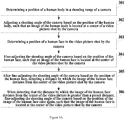
- Fig. 1 is a flow chart showing a camera shooting angle adjusting method according to an exemplary embodiment.
- the method is used in a smart camera. As shown in Fig. 1 , the method may comprise the steps as follows.
- step 101 a position of a human body in a shooting range of a camera is determined.
- a shooting angle of the camera is adjusted based on the position of the human body, such that an image of the human body is located at a center of a video picture shot by the camera.
- step 103 a position of a human face in the video picture shot by the camera is determined.
- step 104 the shooting angle of the camera is fine-adjusted based on the position of the human face, such that an image of the human face is located at the center of the video picture shot by the camera.
- said determining the position of the human body in the shooting range of the camera comprises: collecting a sound signal sent from a sound source in the shooting range of the camera; detecting if a frequency band of the sound signal is within a preset frequency band; and determining a position of the sound source as the position of the human body if it is detected that the frequency band of the sound signal is within the preset frequency band.
- said determining the position of the human body in the shooting range of the camera comprises: collecting an infrared signal sent by an infrared signal source in the shooting range of the camera; detecting if a spectrum feature of the infrared signal matches a preset spectrum; and determining a position of the infrared signal source as the position of the human body, if it is detected that the spectrum feature of the infrared signal matches the preset spectrum.
- said determining the position of the human face in the video picture shot by the camera comprises: performing facial expression recognition of at least one human face in the video picture shot by the camera; and determining a position of a human face, whose facial expression is a designated facial expression, in the video picture as the position of the human face.
- said determining the position of the human face in the video picture shot by the camera comprises: pushing the video picture to a user terminal connected to the camera; receiving selection instruction information returned by the user terminal, the selection instruction information indicating a human face included in the video picture; and determining a position of the human face indicated by the selection instruction information in the video picture as the position of the human face.
- the method further comprises: after fine-adjusting the shooting angle of the camera based on the position of the human face, detecting a distance by which the image of the human face deviates from the center of the video picture shot by the camera; when detecting that the distance by which the image of the human face deviates from the center of the video picture is greater than a preset distance, fine-adjusting the shooting angle of the camera based on the position of the image of the human face once again, such that the image of the human face is located at the center of the video picture shot by the camera.
- a position of a human body in a shooting range of a camera is determined, a shooting angle of the camera is adjusted so that the camera targets the position of the human body, and then the camera is fine-adjusted based on a position of a human face.
- the shooting angle of the camera is automatically fine-adjusted based on the position of the human face, without the need for users to manually adjust the shooting angle of the camera, thereby reducing the complexity of users' operations and improving the accuracy of adjusting the shooting angle.
- Fig. 2A is a flow chart showing a camera shooting angle adjusting method according to another exemplary embodiment.
- the method is used in a smart camera. As shown in Fig. 2A , the method may comprise the steps as follows.
- step 201 a position of a human body in a shooting range of a camera is determined.
- Fig. 2B is a flow chart showing a process of determining a position of a human body in a shooting range of a camera according to an exemplary embodiment, the method may comprise the following steps.
- step 201 a a sound signal sent from a sound source in the shooting range of the camera is collected.
- step 201b it is detected if a frequency band of the sound signal is within a preset frequency band.
- a position of the sound source is determined as the position of the human body, if it is detected that the frequency band of the sound signal is within the preset frequency band.
- the smart camera can determine a position of a human body based on a sound signal sent from a sound source in a shooting range of the camera.
- the smart camera has mounted therein a sound signal collecting device which collects sound signals sent from the sound source in a preset period of time and takes an average of the sound signals collected in the preset period of time.
- the preset period of time is not restricted, and may be set as 30 seconds or 1 minute. If the average of the sound signals is within a preset frequency band, the position of the sound source is determined as the position of the human body.
- the preset frequency band should be a frequency band in which people normally communicate. For example, the frequency band in which people normally talk is 130-350Hz.
- Fig. 2C is a flow chart showing a process of determining a position of a human body in a shooting range of a camera according to another exemplary embodiment, the method may comprise the following steps.
- step 201d an infrared signal sent by an infrared signal source in the shooting range of the camera is collected.
- step 201e it is detected if a spectrum feature of the infrared signal matches a preset spectrum.
- a position of the infrared signal source is determined as the position of the human body, if it is detected that the spectrum feature of the infrared signal matches the preset spectrum.
- the smart camera may also determine a position of a human body based on a spectrum feature of an infrared signal.
- the spectrum feature of the infrared signal may include among others a frequency of the infrared signal and a wavelength thereof.
- Infrared signals sent by different objects have different spectrum features.
- a spectrum feature of a human body may be set as a preset spectrum. If a spectrum feature of infrared signals sent by an object matches the preset spectrum, the object can be determined as a human body.
- step 202 a shooting angle of the camera is adjusted.
- the shooting angle of the camera is adjusted such that an image of the human body is located at a center of a video picture shot by the camera.
- a micro electric motor is provided within the smart camera. After the smart camera determines the position of the human body, the micro electric motor within the smart camera starts to work to adjust the shooting angle of the camera such that an image of the human body is located at a center of a video picture shot by the camera.
- step 203 a position of a human face in the video picture shot by the camera is determined by performing human face recognition.
- a position of a human face in the video picture shot by the camera is determined by the camera through human face recognition.
- the smart camera determines a position of a human face based on facial features of the human body in the video picture, such as the ears, eyes, mouth and nose, shapes of the facial features and their geometrical relations.
- step 204 the shooting angle of the camera is fine-adjusted based on the position of the human face.
- the shooting angle of the camera may be fine-adjusted such that an image of the human face is located at the center of the video picture shot by the camera.
- the position of one of the human faces may be determined, and the fine-adjustment may be performed subsequently based on the determined position of the human face.
- the method of determining the position of one of the human faces may be as below.
- Fig. 2D is a flow chart showing a process of determining a position of a human face according to an exemplary embodiment, the method may comprise the following steps.
- step 203a facial expression recognition is performed of at least one human face in the video picture shot by the camera.
- step 203b a position of a human face, whose facial expression is a designated facial expression, in the video picture is determined as the position of the human face.
- the human face to be shot by the camera may be determined through facial expression recognition. For example, a smiling facial expression is preset as a designated facial expression.
- the shooting angle of the camera is fine-adjusted such that the human face having the smiling facial expression is located at a center of a video picture shot by the camera.
- Fig. 2E is a schematic diagram showing how to adjust a shooting angle of a camera according to an exemplary embodiment.
- the video picture 20 shown in Fig. 2E includes three human faces 20a, 20b and 20c.
- the camera detects that one human face 20c has a smiling facial expression.
- the shooting angle of the camera is fine-adjusted such that the human face 20c having a smiling facial expression is located at a center of the video picture.
- the step s03 may comprise the following steps.
- step 203c the video picture is pushed to a user terminal connected to the camera.
- step 203d selection instruction information returned by the user terminal is received, the selection instruction information indicating a human face included in the video picture.
- step 203e a position of the human face indicated by the selection instruction information in the video picture is determined as the position of the human face.
- the camera may push the shot video picture to a user terminal connected thereto.
- the user may select a human face to be shot.
- the camera determines a position of the human face indicated by the selection instruction information in the video picture as the position of the human face.
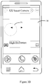
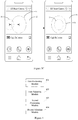
- Fig. 2G is a schematic diagram showing how to adjust a shooting angle of a camera according to another exemplary embodiment.
- the video picture shown in Fig. 2G is one transmitted by the camera to the user terminal and displayed in the user terminal.
- the video picture includes three human faces A, B and C.
- the user terminal sends coordinate information of the human face C to the camera.
- the camera determines that the user has selected the human face C based on the coordinate information. Then, the shooting angle of the camera is fine-adjusted such that an image of the human face C is located at a center of the video picture.
- a position of a human body in a shooting range of a camera is determined, a shooting angle of the camera is adjusted so that the camera targets the position of the human body, and then the camera is fine-adjusted based on a position of a human face.
- the shooting angle of the camera is automatically fine-adjusted based on the position of the human face, without the need for users to manually adjust the shooting angle of the camera, thereby reducing the complexity of users' operations and improving the accuracy of adjusting the shooting angle.
- a sound signal or an infrared signal sent by a human body in a shooting range is collected, and a position of the human body in the shooting range can be determined based on a preset frequency band or time-frequency spectrum, so that the human body in the shooting range can be tracked accurately and effectively. Accordingly, a shooting angle of a camera can be adjusted to adapt to the position of the human body, and it can be avoided that the position of an animal or object other than a human body is determined as the position of the human body.
- a human face to be shot by the camera can be determined.
- the camera pushes a shot video picture to a user terminal connected to the camera; and by receiving the user terminal's selection instruction information, a human face to be shot can be determined. Accordingly, a shooting angle can be fine-adjusted. As such, it is convenient, when there are multiple human faces in the shooting range, to adjust the shooting angle of the camera based on the user's needs, so that the human face to be shot can be displayed at the center of the video picture.
- Fig. 3A is a flow chart showing a camera shooting angle adjusting method according to yet another exemplary embodiment.
- the method is used in a smart camera. As shown in Fig. 3A , the method may comprise the steps as follows.
- step 301 a position of a human body in a shooting range of a camera is determined.
- step 302 a shooting angle of the camera is adjusted.
- step 303 a position of a human face in the video picture shot by the camera is determined through human face recognition.
- step 304 the shooting angle of the camera is fine-adjusted based on the position of the human face.
- steps 301-304 For the implementation of steps 301-304, reference can be made to the description of steps 201-204 in the embodiment shown in Fig. 2 , and the description thereof will not be repeated here.
- step 305 after the shooting angle of the camera is fine-adjusted based on the position of the human face, a distance by which the image of the human face deviates from the center of the video picture shot by the camera is detected.
- the camera detects a distance by which the image of the human face deviates from a center of the video picture shot by the camera, in order to prevent the position of the human face from exceeding the shooting range of the camera so as to ensure better shooting effect.
- Fig. 3B is a schematic diagram showing how to detect a deviation distance of a human face.
- the center of the video picture 30 shot by the camera in Fig. 3B is taken as the starting point.
- a distance from the center of the video picture 30 to a center of the image 31 of the human face is calculated.
- the distance from the center of the video picture 30 to the center of the image 31 of the human face is taken as the distance by which the image of the human face deviates from the center of the video picture shot by the camera.
- step 306 when detecting that the distance by which the image of the human face deviates from the center of the video picture is greater than a preset distance, the shooting angle of the camera is fine-adjusted based on the position of the image of the human face once again, such that the image of the human face is located at the center of the video picture shot by the camera.
- the camera may designate the center of the video picture shot by the camera as a center of a circle and designate a preset distance as its radius.
- the shooting angle of the camera is fine-adjusted based on the position of the image of the human face once again.
- Fig. 3C is a schematic diagram showing how to adjust a position of a human face.
- the shooting angle of the camera is fine-adjusted such that the image 33 of the human face is located at the center of the video picture 32 once again.
- the shooting angle of the camera is not adjusted immediately when the camera detects that the distance from the center of the video picture to the center of the image of the human face is greater than the preset distance, but is adjusted after a preset period of time (which may be 5 or 10s for example).
- the camera fine-adjusts the shooting angle based on the position of the image of the human face, only when the distance from the center of the video picture to the center of the image at the position of the human face is greater than the preset distance for a duration longer than the preset period of time.
- the detection of the distance by which the image of the human face deviates from the center of the video picture and the preset distance are not defined by the embodiment but may be set by developers or users according to the actual needs.
- a position of a human body in a shooting range of a camera is determined, a shooting angle of the camera is adjusted so that the camera targets the position of the human body, and then the camera is fine-adjusted based on a position of a human face.
- the shooting angle of the camera is automatically fine-adjusted based on the position of the human face, without the need for users to manually adjust the shooting angle of the camera, thereby reducing the complexity of users' operations and improving the accuracy of adjusting the shooting angle.
- a sound signal or an infrared signal sent by a human body in a shooting range is collected, and a position of the human body in the shooting range can be determined based on a preset frequency band or time-frequency spectrum, so that the human body in the shooting range can be tracked accurately and effectively. Accordingly, a shooting angle of a camera can be adjusted to adapt to the position of the human body, and it can be avoided that the position of an animal or object other than a human body is determined as the position of the human body.
- a human face to be shot by the camera can be determined.
- the camera pushes a shot video picture to a user terminal connected to the camera; and by receiving the user terminal's selection instruction information, a human face to be shot can be determined. Accordingly, a shooting angle can be fine-adjusted. As such, it is convenient, when there are multiple human faces in the shooting range, to adjust the shooting angle of the camera based on the user's needs, so that the human face to be shot can be displayed at the center of the video picture.
- a distance between the center of the video picture and an image of the human face is determined and, if the distance between the center of the video picture and the image of the human face is greater than a preset distance, the shooting angle of the camera is fine-adjusted such that the image of the human face is located at the center of the video picture, thereby achieving the best shooting effect.
- Fig. 4 is a schematic diagram illustrating a camera shooting angle adjusting apparatus according to an exemplary embodiment.
- the apparatus may be used in a smart camera.
- the apparatus comprises but is not limited to comprise a first positioning module 401, a first adjusting module 402, a second positioning module 403 and a second adjusting module 404.
- the first positioning module 401 is configured to determine a position of a human body in a shooting range of a camera.
- the first adjusting module 402 is configured to adjust a shooting angle of the camera based on the position of the human body determined by the first positioning module 401, such that an image of the human body is located at a center of a video picture shot by the camera.
- the second positioning module 403 is configured to determine a position of a human face in the video picture shot by the camera.
- the second adjusting module 404 is configured to fine-adjust the shooting angle of the camera based on the position of the human face determined by the second positioning module 403, such that an image of the human face is located at the center of the video picture shot by the camera.
- a position of a human body in a shooting range of a camera is determined, a shooting angle of the camera is adjusted so that the camera targets the position of the human body, and then the camera is fine-adjusted based on a position of a human face.
- the shooting angle of the camera is automatically fine-adjusted based on the position of the human face, without the need for users to manually adjust the shooting angle of the camera, thereby reducing the complexity of users' operations and improving the accuracy of adjusting the shooting angle.
- Fig. 5 is a schematic diagram illustrating a camera shooting angle adjusting apparatus according to another exemplary embodiment.
- the apparatus may be used in a smart camera.
- the apparatus comprises but is not limited to comprise a first positioning module 501, a first adjusting module 502, a second positioning module 503 and a second adjusting module 504.
- the first positioning module 501 is configured to determine a position of a human body in a shooting range of a camera.
- the first adjusting module 502 is configured to adjust a shooting angle of the camera based on the position of the human body determined by the first positioning module 501, such that an image of the human body is located at a center of a video picture shot by the camera.
- the second positioning module 503 is configured to determine a position of a human face in the video picture shot by the camera.
- the second adjusting module 504 is configured to fine-adjust the shooting angle of the camera based on the position of the human face determined by the second positioning module 503, such that an image of the human face is located at the center of the video picture shot by the camera.
- the first positioning module 501 comprises a sound collecting sub-module 501a and a frequency band detecting sub-module 501b.
- the sound collecting sub-module 501a is configured to collect a sound signal sent from a sound source in the shooting range of the camera.
- the frequency band detecting sub-module 501b is configured to detect if a frequency band of the sound signal collected by the sound collecting sub-module 501a is within a preset frequency band.
- a position of the sound source is determined as the position of the human body, if it is detected that the frequency band of the sound signal collected by the sound collecting sub-module 501a is within the preset frequency band.
- the first positioning module 501 further comprises an infrared signal collecting sub-module 501c and a spectrum detecting sub-module 501d.
- the infrared signal collecting sub-module 501c is configured to collect an infrared signal sent by an infrared signal source in the shooting range of the camera.
- the spectrum detecting sub-module 501d is configured to detect if a spectrum feature of the infrared signal collected by the infrared signal collecting sub-module 501c matches a preset spectrum.
- a position of the infrared signal source is determined as the position of the human body, if it is detected that the spectrum feature of the infrared signal collected by the infrared signal collecting sub-module 501c matches the preset spectrum.
- the second positioning module 503 comprises a facial expression recognizing sub-module 503a and a first positioning sub-module 503b.
- the facial expression recognizing sub-module 503a is configured to perform facial expression recognition of at least one human face in the video picture shot by the camera.
- the first positioning sub-module 503b is configured to determine a position of a human face, whose facial expression recognized by the facial expression recognizing sub-module 503a is a designated facial expression, in the video picture as the position of the human face.
- the second positioning module 503 further comprises an image pushing sub-module 503c, an information receiving sub-module 503d and a second positioning sub-module 503e.
- the image pushing sub-module 503c is configured to push the video picture to a user terminal connected to the camera.
- the information receiving sub-module 503d is configured to receive selection instruction information returned by the user terminal, the selection instruction information indicating a human face included in the video picture.
- the second positioning sub-module 503e is configured to determine a position of the human face indicated by the selection instruction information received by the information receiving sub-module 503d in the video picture as the position of the human face.
- the apparatus further comprises a distance detecting module 505.
- the distance detecting module 505 is configured to, after the shooting angle of the camera is fine-adjusted based on the position of the human face, detect a distance by which the image of the human face deviates from the center of the video picture shot by the camera.
- the second adjusting module 504 is further configured to, when it is detected that the distance by which the center of the image at the position of the human face deviates from the center of the video picture, detected by the distance detecting module 505, is greater than a preset distance, fine-adjust the shooting angle of the camera based on the position of the image of the human face once again, such that the image of the human face is located at the center of the video picture shot by the camera.
- a position of a human body in a shooting range of a camera is determined, a shooting angle of the camera is adjusted so that the camera targets the position of the human body, and then the camera is fine-adjusted based on a position of a human face.
- the shooting angle of the camera is automatically fine-adjusted based on the position of the human face, without the need for users to manually adjust the shooting angle of the camera, thereby reducing the complexity of users' operations and improving the accuracy of adjusting the shooting angle.
- a sound signal or an infrared signal sent by a human body in a shooting range is collected, and a position of the human body in the shooting range can be determined based on a preset frequency band or time-frequency spectrum, so that the human body in the shooting range can be tracked accurately and effectively. Accordingly, a shooting angle of a camera can be adjusted to adapt to the position of the human body, and it can be avoided that the position of an animal or object other than a human body is determined as the position of the human body.
- a human face to be shot by the camera can be determined.
- the camera pushes a shot video picture to a user terminal connected to the camera; and by receiving the user terminal's selection instruction information, a human face to be shot can be determined. Accordingly, a shooting angle can be fine-adjusted. As such, it is convenient, when there are multiple human faces in the shooting range, to adjust the shooting angle of the camera based on the user's needs, so that the human face to be shot can be displayed at the center of the video picture.
- a distance between the center of the video picture and an image of the human face is determined and, if the distance between the center of the video picture and the image of the human face is greater than a preset distance, the shooting angle of the camera is fine-adjusted such that the image of the human face is located at the center of the video picture, thereby achieving the best shooting effect.
- a camera shooting angle adjusting apparatus is provided according to yet another exemplary embodiment of the present invention.
- the apparatus can realize the camera shooting angle adjusting method of the present invention, and comprises a processor and a memory configured to store instructions executable by the processor.
- the processor is configured to: determine a position of a human body in a shooting range of a camera; adjust a shooting angle of the camera based on the position of the human body, such that an image of the human body is located at a center of a video picture shot by the camera; determine a position of a human face in the video picture shot by the camera; and fine-adjust the shooting angle of the camera based on the position of the human face, such that an image of the human face is located at the center of the video picture shot by the camera.
- said determining the position of the human body in the shooting range of the camera comprises: collecting a sound signal sent from a sound source in the shooting range of the camera; detecting if a frequency band of the sound signal is within a preset frequency band; and determining a position of the sound source as the position of the human body if it is detected that the frequency band of the sound signal is within the preset frequency band.
- said determining the position of the human body in the shooting range of the camera comprises: collecting an infrared signal sent by an infrared signal source in the shooting range of the camera; detecting if a spectrum feature of the infrared signal matches a preset spectrum; and determining a position of the infrared signal source as the position of the human body if it is detected that the spectrum feature of the infrared signal matches the preset spectrum.
- said determining the position of the human face in the video picture shot by the camera comprises: performing facial expression recognition of at least one human face in the video picture shot by the camera; and determining a position of a human face, whose facial expression is a designated facial expression, in the video picture as the position of the human face.
- said determining the position of the human face in the video picture shot by the camera comprises: pushing the video picture to a user terminal connected to the camera; receiving selection instruction information returned by the user terminal, the selection instruction information indicating a human face included in the video picture; and determining a position of the human face indicated by the selection instruction information in the video picture as the position of the human face.
- the processor is further configured to: after fine-adjusting the shooting angle of the camera based on the position of the human face, detect a distance by which the image of the human face deviates from the center of the video picture shot by the camera; when detecting that the distance by which the image of the human face deviates from the center of the video picture is greater than a preset distance, fine-adjust the shooting angle of the camera based on the position of the image of the human face such that the image of the human face is located at the center of the video picture shot by the camera.
- Fig. 6 is a schematic diagram illustrating a camera shooting angle adjusting apparatus 600 according to yet another exemplary embodiment.
- the apparatus 600 may be a smart camera.
- the apparatus 600 may comprise one or more following components: a processing component 602, a memory 604, a power component 606, a multimedia component 608, an audio component 610, a sensor component 614 and a communication component 616.
- the processing component 602 typically controls overall operations of the apparatus 600, such as the operations associated with display, telephone calls, data communications, camera operations and recording operations.
- the processing component 602 may include one or more processors 618 to execute instructions to perform all or part of the steps in the above described methods.
- the processing component 602 may include one or more modules which facilitate the interaction between the processing component 602 and other components.
- the processing component 602 may comprise a multimedia module to facilitate the interaction between the multimedia component 608 and the processing component 602.
- the memory 604 is configured to store various types of data to support the operation of the apparatus 600. Examples of such data comprise instructions for any applications or methods operated on the apparatus 600, contact data, phonebook data, messages, pictures, video, etc.
- the memory 604 may be implemented by using any type of volatile or non-volatile memory devices, or a combination thereof, such as a static random access memory (SRAM), an electrically erasable programmable read-only memory (EEPROM), an erasable programmable read-only memory (EPROM), a programmable read-only memory (PROM), a read-only memory (ROM), a magnetic memory, a flash memory, a magnetic or optical disk.
- the memory 604 also stores one or more modules configured to, when being executed by the one or more processors 618, perform all or a part of the steps of the method shown in Fig. 1, 2A or 3A .
- the power component 606 provides power to various components of the apparatus 600.
- the power component 606 may comprise a power management system, one or more power sources, and any other components associated with the generation, management, and distribution of power in the apparatus 600.
- the multimedia component 608 comprises a screen providing an output interface between the apparatus 600 and the user.
- the screen may comprise a liquid crystal display (LCD) and a touch panel (TP). If the screen comprises the touch panel, the screen may be implemented as a touch screen to receive input signals from the user.
- the touch panel comprises one or more touch sensors to sense touches, swipes and gestures on the touch panel. The touch sensors may not only sense a boundary of a touch or swipe action, but also sense a period of time and a pressure associated with the touch or swipe action.
- the multimedia component 608 includes a front camera and/or a rear camera.
- the front camera and/or the rear camera may receive an external multimedia datum while the apparatus 600 is in an operation mode, such as a photographing mode or a video mode.
- an operation mode such as a photographing mode or a video mode.
- Each of the front and rear cameras may be a fixed optical lens system or have a focus and optical zoom capability.
- the audio component 610 is configured to output and/or input audio signals.
- the audio component 610 includes a microphone (MIC) configured to receive an external audio signal when the apparatus 600 is in an operation mode, such as a call mode, a recording mode, and a voice recognition mode.
- the received audio signal may be further stored in the memory 604 or transmitted via the communication component 616.
- the audio component 610 further includes a speaker to output audio signals.
- the sensor component 614 comprises one or more sensors to provide status assessments of various aspects of the apparatus 600. For instance, the sensor component 614 may detect an open/closed status of the apparatus 600, relative positioning of components, e.g., the display and the keypad, of the apparatus 600, a change in position of the apparatus 600 or a component of the apparatus 600, a presence or absence of user's contact with the apparatus 600, an orientation or an acceleration/deceleration of the apparatus 600, and a change in temperature of the apparatus 600.
- the sensor component 614 may include a proximity sensor configured to detect the presence of nearby objects without any physical contact.
- the sensor component 614 may also include a light sensor, such as a CMOS or CCD image sensor, for use in imaging applications.
- the sensor component 614 may also include an accelerometer sensor, a gyroscope sensor, a magnetic sensor, a pressure sensor or a temperature sensor.
- the communication component 616 is configured to facilitate communication, wired or wirelessly, between the apparatus 600 and other devices.
- the apparatus 600 can access a wireless network based on a communication standard, such as WiFi, 2G, or 3G, or a combination thereof.
- the communication component 616 receives a broadcast signal or broadcast associated information from an external broadcast management system via a broadcast channel.
- the communication component 616 further includes a near field communication (NFC) module to facilitate short-range communications.
- NFC near field communication
- the apparatus 600 may be implemented with one or more application specific integrated circuits (ASICs), digital signal processors (DSPs), digital signal processing devices (DSPDs), programmable logic devices (PLDs), field programmable gate arrays (FPGAs), controllers, micro-controllers, microprocessors, or other electronic components, for performing the above described methods.
- ASICs application specific integrated circuits
- DSPs digital signal processors
- DSPDs digital signal processing devices
- PLDs programmable logic devices
- FPGAs field programmable gate arrays
- controllers micro-controllers, microprocessors, or other electronic components, for performing the above described methods.
- non-transitory computer-readable storage medium comprising instructions, such as comprised in the memory 604, executable by the processor 618 in the apparatus 600, for performing the above-described methods.
- the non-transitory computer-readable storage medium may be a ROM, a RAM, a CD-ROM, a magnetic tape, a floppy disc, an optical data storage device, and the like.
- modules are referred to in apparatus embodiments for carrying out various steps of the described method(s) it will be understood that these modules may be implemented in hardware, in software, or a combination of the two.
- the modules When implemented in hardware, the modules may be implemented as one or more hardware modules, such as one or more application specific integrated circuits.
- the modules When implemented in software, the modules may be implemented as one or more computer programs that are executed on one or more processors.
Landscapes
- Engineering & Computer Science (AREA)
- Multimedia (AREA)
- Signal Processing (AREA)
- Human Computer Interaction (AREA)
- Physics & Mathematics (AREA)
- Health & Medical Sciences (AREA)
- General Physics & Mathematics (AREA)
- Oral & Maxillofacial Surgery (AREA)
- General Health & Medical Sciences (AREA)
- Theoretical Computer Science (AREA)
- Computational Linguistics (AREA)
- Audiology, Speech & Language Pathology (AREA)
- Acoustics & Sound (AREA)
- Studio Devices (AREA)
- Circuit For Audible Band Transducer (AREA)
- Image Analysis (AREA)
Abstract
Description
- The present invention is related to the field of smart homes, and more particularly, to a camera shooting angle adjusting method and apparatus, a computer program and a recording medium.
- With popularization of smart devices and rapid development of network technologies, smart cameras are becoming more and more popular in people's daily life and are widely used in such scenes as security, automatic control and remote video interaction.
- In the related arts, shooting angles of smart cameras are fixed during their use. When users want to adjust the shooting angles of smart cameras, they may manually adjust the same using control devices of the smart cameras. However, such manual adjustments are complex, and the adjustment efficiency is low.
- The present invention provides a camera shooting angle adjusting method and apparatus, a computer program and a recording medium. The technical solutions are as below.
- According to a first aspect of embodiments of the present invention, there is provided a camera shooting angle adjusting method, comprising: determining a position of a human body in a shooting range of a camera; adjusting a shooting angle of the camera based on the position of the human body, such that an image of the human body is located at a center of a video picture shot by the camera; determining a position of a human face in the video picture shot by the camera; and fine-adjusting the shooting angle of the camera based on the position of the human face, such that an image of the human face is located at the center of the video picture shot by the camera.
- Optionally, said determining the position of the human body in the shooting range of the camera comprises: collecting a sound signal sent from a sound source in the shooting range of the camera; detecting if a frequency band of the sound signal is within a preset frequency band; and determining a position of the sound source as the position of the human body if it is detected that the frequency band of the sound signal is within the preset frequency band.
- Optionally, said determining the position of the human body in the shooting range of the camera comprises: collecting an infrared signal sent by an infrared signal source in the shooting range of the camera; detecting if a spectrum feature of the infrared signal matches a preset spectrum; and determining a position of the infrared signal source as the position of the human body if it is detected that the spectrum feature of the infrared signal matches the preset spectrum.
- Optionally, said determining the position of the human face in the video picture shot by the camera comprises: performing facial expression recognition of at least one human face in the video picture shot by the camera; and determining a position of a human face, whose facial expression is a designated facial expression, in the video picture as the position of the human face.
- Optionally, said determining the position of the human face in the video picture shot by the camera comprises: pushing the video picture to a user terminal connected to the camera; receiving selection instruction information returned by the user terminal, the selection instruction information indicating a human face included in the video picture; and determining a position of the human face indicated by the selection instruction information in the video picture as the position of the human face.
- Optionally, the method further comprises: after fine-adjusting the shooting angle of the camera based on the position of the human face, detecting a distance by which a facial image of the human face deviates from the center of the video picture shot by the camera; when detecting that the distance by which the facial image of the human face deviates from the center of the video picture is greater than a preset distance, fine-adjusting the shooting angle of the camera based on the image at the position of the human face once again, such that the image of the human face is located at the center of the video picture shot by the camera.
- According to a second aspect of embodiments of the present invention, there is provided a camera shooting angle adjusting apparatus, comprising: a first positioning module configured to determine a position of a human body in a shooting range of a camera; a first adjusting module configured to adjust a shooting angle of the camera based on the position of the human body determined by the first positioning module, such that an image of the human body is located at a center of a video picture shot by the camera; a second positioning module configured to determine a position of a human face in the video picture shot by the camera; and a second adjusting module configured to fine-adjust the shooting angle of the camera based on the position of the human face determined by the second positioning module, such that an image of the human face is located at the center of the video picture shot by the camera.
- Optionally, the first positioning module comprises: a sound collecting sub-module configured to collect a sound signal sent from a sound source in the shooting range of the camera; and a frequency band detecting sub-module configured to detect if a frequency band of the sound signal collected by the sound collecting sub-module is within a preset frequency band. A position of the sound source is determined as the position of the human body, if it is detected that the frequency band of the sound signal collected by the sound collecting sub-module is within the preset frequency band.
- Optionally, the first positioning module comprises: an infrared signal collecting sub-module configured to collect an infrared signal sent by an infrared signal source in the shooting range of the camera; and a spectrum detecting sub-module configured to detect if a spectrum feature of the infrared signal collected by the infrared signal collecting sub-module matches a preset spectrum. A position of the infrared signal source is determined as the position of the human body, if it is detected that the spectrum feature of the infrared signal collected by the infrared signal collecting sub-module matches the preset spectrum.
- Optionally, the second positioning module comprises: a facial expression recognizing sub-module configured to perform facial expression recognition of at least one human face in the video picture shot by the camera; and a first positioning sub-module configured to determine a position of a human face, whose facial expression recognized by the facial expression recognizing sub-module is a designated facial expression, in the video picture as the position of the human face.
- Optionally, the second positioning module comprises: an image pushing sub-module configured to push the video picture to a user terminal connected to the camera; an information receiving sub-module configured to receive selection instruction information returned by the user terminal, the selection instruction information indicating a human face included in the video picture; and a second positioning sub-module configured to determine a position of the human face indicated by the selection instruction information received by the information receiving sub-module in the video picture as the position of the human face.
- Optionally, the apparatus further comprises a distance detecting module configured to, after the shooting angle of the camera is fine-adjusted based on the position of the human face, detect a distance by which the image of the human face deviates from the center of the video picture shot by the camera. The second adjusting module is further configured to, when it is detected that the distance by which the image of the human face deviates from the center of the video picture, detected by the distance detecting module, is greater than a preset distance, fine-adjust the shooting angle of the camera based on the position of the image of the human face once again, such that the image of the human face is located at the center of the video picture shot by the camera.
- According to a third aspect of embodiments of the present invention, there is provided a camera shooting angle adjusting apparatus, comprising a processor and a memory configured to store instructions executable by the processor. The processor is configured to: determine a position of a human body in a shooting range of a camera; adjust a shooting angle of the camera based on the position of the human body, such that an image of the human body is located at a center of a video picture shot by the camera; determine a position of a human face in the video picture shot by the camera; and fine-adjust the shooting angle of the camera based on the position of the human face, such that an image of the human face is located at the center of the video picture shot by the camera.
- In one particular embodiment, the steps of the camera shooting angle adjusting method are determined by computer program instructions.
- Consequently, according to a seventh aspect, the invention is also directed to a computer program for executing the steps of a camera shooting angle adjusting method as described above when this program is executed by a computer.
- This program can use any programming language and take the form of source code, object code or a code intermediate between source code and object code, such as a partially compiled form, or any other desirable form.
- The invention is also directed to a computer-readable information medium or recording medium containing instructions of a computer program as described above.
- The information medium or recording medium can be any entity or device capable of storing the program. For example, the support can include storage means such as a ROM, for example a CD ROM or a microelectronic circuit ROM, or magnetic storage means, for example a diskette (floppy disk) or a hard disk.
- Alternatively, the information medium can be an integrated circuit in which the program is incorporated, the circuit being adapted to execute the method in question or to be used in its execution.
- The technical solutions of the embodiments of this invention have the following advantageous effects.
- By determining a position of a human body in a shooting range of a camera, adjusting a shooting angle of the camera so that the camera targets the position of the human body and then fine-adjusting the camera based on a position of a human face, the shooting angle of the camera is automatically fine-adjusted based on the position of the human face, without the need for users to manually adjust the shooting angle of the camera, thereby reducing the complexity of users' operations and improving the accuracy of adjusting the shooting angle.
- It should be understood that both the foregoing general description and the following detailed description are only exemplary and explanatory and are not restrictive of the invention.
- The accompanying drawings, which are incorporated in and constitute a part of this specification, illustrate embodiments consistent with the invention and, together with the description, serve to explain the principles of the invention.
-
Fig. 1 is a flow chart showing a camera shooting angle adjusting method according to an exemplary embodiment. -
Fig. 2A is a flow chart showing a camera shooting angle adjusting method according to another exemplary embodiment. -
Fig. 2B is a flow chart showing a process of determining a position of a human body in a shooting range of a camera according to an exemplary embodiment. -
Fig. 2C is a flow chart showing a process of determining a position of a human body in a shooting range of a camera according to another exemplary embodiment. -
Fig. 2D is a flow chart showing a process of determining a position of a human face according to an exemplary embodiment. -
Fig. 2E is a schematic diagram showing how to adjust a shooting angle of a camera according to an exemplary embodiment. -
Fig. 2F is a flow chart showing a process of determining a position of a human face according to another exemplary embodiment. -
Fig. 2G is a schematic diagram showing how to adjust a shooting angle of a camera according to another exemplary embodiment. -
Fig. 3A is a flow chart showing a camera shooting angle adjusting method according to yet another exemplary embodiment. -
Fig. 3B is a schematic diagram showing how to detect a deviation distance of a human face according to an exemplary embodiment. -
Fig. 3C is a schematic diagram showing how to adjust a position of a human face according to an exemplary embodiment. -
Fig. 4 is a block diagram illustrating a camera shooting angle adjusting apparatus according to an exemplary embodiment. -
Fig. 5 is a block diagram illustrating a camera shooting angle adjusting apparatus according to another exemplary embodiment. -
Fig. 6 is a block diagram illustrating a camera shooting angle adjusting apparatus according to yet another exemplary embodiment. - Reference will now be made in detail to exemplary embodiments, examples of which are illustrated in the accompanying drawings. The following description refers to the accompanying drawings in which the same numbers in different drawings represent the same or similar elements unless otherwise represented. The implementations set forth in the following description of exemplary embodiments do not represent all implementations consistent with the invention. Instead, they are merely examples of apparatuses and methods consistent with aspects related to the invention as recited in the appended claims.
-
Fig. 1 is a flow chart showing a camera shooting angle adjusting method according to an exemplary embodiment. The method is used in a smart camera. As shown inFig. 1 , the method may comprise the steps as follows. - In
step 101, a position of a human body in a shooting range of a camera is determined. - In
step 102, a shooting angle of the camera is adjusted based on the position of the human body, such that an image of the human body is located at a center of a video picture shot by the camera. - In
step 103, a position of a human face in the video picture shot by the camera is determined. - In
step 104, the shooting angle of the camera is fine-adjusted based on the position of the human face, such that an image of the human face is located at the center of the video picture shot by the camera. - Optionally, said determining the position of the human body in the shooting range of the camera comprises: collecting a sound signal sent from a sound source in the shooting range of the camera; detecting if a frequency band of the sound signal is within a preset frequency band; and determining a position of the sound source as the position of the human body if it is detected that the frequency band of the sound signal is within the preset frequency band.
- Optionally, said determining the position of the human body in the shooting range of the camera comprises: collecting an infrared signal sent by an infrared signal source in the shooting range of the camera; detecting if a spectrum feature of the infrared signal matches a preset spectrum; and determining a position of the infrared signal source as the position of the human body, if it is detected that the spectrum feature of the infrared signal matches the preset spectrum.
- Optionally, said determining the position of the human face in the video picture shot by the camera comprises: performing facial expression recognition of at least one human face in the video picture shot by the camera; and determining a position of a human face, whose facial expression is a designated facial expression, in the video picture as the position of the human face.
- Optionally, said determining the position of the human face in the video picture shot by the camera comprises: pushing the video picture to a user terminal connected to the camera; receiving selection instruction information returned by the user terminal, the selection instruction information indicating a human face included in the video picture; and determining a position of the human face indicated by the selection instruction information in the video picture as the position of the human face.
- Optionally, the method further comprises: after fine-adjusting the shooting angle of the camera based on the position of the human face, detecting a distance by which the image of the human face deviates from the center of the video picture shot by the camera; when detecting that the distance by which the image of the human face deviates from the center of the video picture is greater than a preset distance, fine-adjusting the shooting angle of the camera based on the position of the image of the human face once again, such that the image of the human face is located at the center of the video picture shot by the camera.
- To sum up, in the camera shooting angle adjusting method according to the embodiment of the invention, a position of a human body in a shooting range of a camera is determined, a shooting angle of the camera is adjusted so that the camera targets the position of the human body, and then the camera is fine-adjusted based on a position of a human face. As such, the shooting angle of the camera is automatically fine-adjusted based on the position of the human face, without the need for users to manually adjust the shooting angle of the camera, thereby reducing the complexity of users' operations and improving the accuracy of adjusting the shooting angle.
-
Fig. 2A is a flow chart showing a camera shooting angle adjusting method according to another exemplary embodiment. The method is used in a smart camera. As shown inFig. 2A , the method may comprise the steps as follows. - In
step 201, a position of a human body in a shooting range of a camera is determined. - In a possible implementation, referring to
Fig. 2B which is a flow chart showing a process of determining a position of a human body in a shooting range of a camera according to an exemplary embodiment, the method may comprise the following steps. - In
step 201 a, a sound signal sent from a sound source in the shooting range of the camera is collected. - In step 201b, it is detected if a frequency band of the sound signal is within a preset frequency band.
- In
step 201c, a position of the sound source is determined as the position of the human body, if it is detected that the frequency band of the sound signal is within the preset frequency band. - The smart camera can determine a position of a human body based on a sound signal sent from a sound source in a shooting range of the camera. For example, the smart camera has mounted therein a sound signal collecting device which collects sound signals sent from the sound source in a preset period of time and takes an average of the sound signals collected in the preset period of time. The preset period of time is not restricted, and may be set as 30 seconds or 1 minute. If the average of the sound signals is within a preset frequency band, the position of the sound source is determined as the position of the human body. Specifically, as the position of the human body is to be determined, the preset frequency band should be a frequency band in which people normally communicate. For example, the frequency band in which people normally talk is 130-350Hz.
- In another possible implementation, referring to
Fig. 2C which is a flow chart showing a process of determining a position of a human body in a shooting range of a camera according to another exemplary embodiment, the method may comprise the following steps. - In
step 201d, an infrared signal sent by an infrared signal source in the shooting range of the camera is collected. - In
step 201e, it is detected if a spectrum feature of the infrared signal matches a preset spectrum. - In
step 201f, a position of the infrared signal source is determined as the position of the human body, if it is detected that the spectrum feature of the infrared signal matches the preset spectrum. - In addition to or instead of determining a position of a human body based on sound signals sent from a sound source in a shooting range of the camera, the smart camera may also determine a position of a human body based on a spectrum feature of an infrared signal. The spectrum feature of the infrared signal may include among others a frequency of the infrared signal and a wavelength thereof. Infrared signals sent by different objects have different spectrum features. In a possible implementation of the embodiment, a spectrum feature of a human body may be set as a preset spectrum. If a spectrum feature of infrared signals sent by an object matches the preset spectrum, the object can be determined as a human body.
- In
step 202, a shooting angle of the camera is adjusted. - The shooting angle of the camera is adjusted such that an image of the human body is located at a center of a video picture shot by the camera.
- Specifically, a micro electric motor is provided within the smart camera. After the smart camera determines the position of the human body, the micro electric motor within the smart camera starts to work to adjust the shooting angle of the camera such that an image of the human body is located at a center of a video picture shot by the camera.
- In
step 203, a position of a human face in the video picture shot by the camera is determined by performing human face recognition. - After determining the position of the human body, to obtain better shooting effect, a position of a human face in the video picture shot by the camera is determined by the camera through human face recognition. Specifically, the smart camera determines a position of a human face based on facial features of the human body in the video picture, such as the ears, eyes, mouth and nose, shapes of the facial features and their geometrical relations.
- In
step 204, the shooting angle of the camera is fine-adjusted based on the position of the human face. - When there is only one human face in the video picture shot by the camera, the shooting angle of the camera may be fine-adjusted such that an image of the human face is located at the center of the video picture shot by the camera.
- Optionally, when there are multiple human faces in the video picture shot by the camera, the position of one of the human faces may be determined, and the fine-adjustment may be performed subsequently based on the determined position of the human face. When there are multiple human faces in the video picture shot by the camera, the method of determining the position of one of the human faces may be as below.
- In a possible implementation, referring to
Fig. 2D which is a flow chart showing a process of determining a position of a human face according to an exemplary embodiment, the method may comprise the following steps. - In
step 203a, facial expression recognition is performed of at least one human face in the video picture shot by the camera. - In
step 203b, a position of a human face, whose facial expression is a designated facial expression, in the video picture is determined as the position of the human face. - When there are multiple human faces in the video picture shot by the camera, the human face to be shot by the camera may be determined through facial expression recognition. For example, a smiling facial expression is preset as a designated facial expression. When there are multiple human faces in the video picture shot by the camera and one human face has a smiling facial expression, the shooting angle of the camera is fine-adjusted such that the human face having the smiling facial expression is located at a center of a video picture shot by the camera.
Fig. 2E is a schematic diagram showing how to adjust a shooting angle of a camera according to an exemplary embodiment. Thevideo picture 20 shown inFig. 2E includes threehuman faces human face 20c has a smiling facial expression. Then, the shooting angle of the camera is fine-adjusted such that thehuman face 20c having a smiling facial expression is located at a center of the video picture. - In another possible implementation, referring to
Fig. 2F which is a flow chart showing a process of determining a position of a human face according to another exemplary embodiment, the step s03 may comprise the following steps. - In
step 203c, the video picture is pushed to a user terminal connected to the camera. - In step 203d, selection instruction information returned by the user terminal is received, the selection instruction information indicating a human face included in the video picture.
- In
step 203e, a position of the human face indicated by the selection instruction information in the video picture is determined as the position of the human face. - Optionally, when there are multiple human faces in the video picture shot by the camera, the camera may push the shot video picture to a user terminal connected thereto. The user may select a human face to be shot. When receiving selection instruction information returned by the user terminal, the camera determines a position of the human face indicated by the selection instruction information in the video picture as the position of the human face.
Fig. 2G is a schematic diagram showing how to adjust a shooting angle of a camera according to another exemplary embodiment. The video picture shown inFig. 2G is one transmitted by the camera to the user terminal and displayed in the user terminal. The video picture includes three human faces A, B and C. When the user clicks a region where the human face C is located, the user terminal sends coordinate information of the human face C to the camera. After receiving the coordinate information, the camera determines that the user has selected the human face C based on the coordinate information. Then, the shooting angle of the camera is fine-adjusted such that an image of the human face C is located at a center of the video picture. - To sum up, in the camera shooting angle adjusting method according to the embodiment of the invention, a position of a human body in a shooting range of a camera is determined, a shooting angle of the camera is adjusted so that the camera targets the position of the human body, and then the camera is fine-adjusted based on a position of a human face. As such, the shooting angle of the camera is automatically fine-adjusted based on the position of the human face, without the need for users to manually adjust the shooting angle of the camera, thereby reducing the complexity of users' operations and improving the accuracy of adjusting the shooting angle.
- In addition, by using a sound source or infrared signal detecting method, a sound signal or an infrared signal sent by a human body in a shooting range is collected, and a position of the human body in the shooting range can be determined based on a preset frequency band or time-frequency spectrum, so that the human body in the shooting range can be tracked accurately and effectively. Accordingly, a shooting angle of a camera can be adjusted to adapt to the position of the human body, and it can be avoided that the position of an animal or object other than a human body is determined as the position of the human body.
- In addition, by recognizing a facial expression in the shooting range, a human face to be shot by the camera can be determined. Alternatively, the camera pushes a shot video picture to a user terminal connected to the camera; and by receiving the user terminal's selection instruction information, a human face to be shot can be determined. Accordingly, a shooting angle can be fine-adjusted. As such, it is convenient, when there are multiple human faces in the shooting range, to adjust the shooting angle of the camera based on the user's needs, so that the human face to be shot can be displayed at the center of the video picture.
-
Fig. 3A is a flow chart showing a camera shooting angle adjusting method according to yet another exemplary embodiment. The method is used in a smart camera. As shown inFig. 3A , the method may comprise the steps as follows. - In
step 301, a position of a human body in a shooting range of a camera is determined. - In
step 302, a shooting angle of the camera is adjusted. - In
step 303, a position of a human face in the video picture shot by the camera is determined through human face recognition. - In
step 304, the shooting angle of the camera is fine-adjusted based on the position of the human face. - For the implementation of steps 301-304, reference can be made to the description of steps 201-204 in the embodiment shown in
Fig. 2 , and the description thereof will not be repeated here. - In
step 305, after the shooting angle of the camera is fine-adjusted based on the position of the human face, a distance by which the image of the human face deviates from the center of the video picture shot by the camera is detected. - As the position of the human face is changing in the video shooting process, the camera detects a distance by which the image of the human face deviates from a center of the video picture shot by the camera, in order to prevent the position of the human face from exceeding the shooting range of the camera so as to ensure better shooting effect. Specifically, refer to
Fig. 3B , which is a schematic diagram showing how to detect a deviation distance of a human face. The center of thevideo picture 30 shot by the camera inFig. 3B is taken as the starting point. A distance from the center of thevideo picture 30 to a center of theimage 31 of the human face is calculated. The distance from the center of thevideo picture 30 to the center of theimage 31 of the human face is taken as the distance by which the image of the human face deviates from the center of the video picture shot by the camera. - In
step 306, when detecting that the distance by which the image of the human face deviates from the center of the video picture is greater than a preset distance, the shooting angle of the camera is fine-adjusted based on the position of the image of the human face once again, such that the image of the human face is located at the center of the video picture shot by the camera. - The camera may designate the center of the video picture shot by the camera as a center of a circle and designate a preset distance as its radius. When it is detected that the distance from the center of the video picture to the center of the image the human face is greater than the preset distance (that is, the center of the image of the human face is located outside the circle having the center of the video picture as its center and having the preset distance as its radius), the shooting angle of the camera is fine-adjusted based on the position of the image of the human face once again.
- Specifically, refer to
Fig. 3C , which is a schematic diagram showing how to adjust a position of a human face. InFig. 3C , when it is detected that the distance from the center of thevideo picture 32 to the center of theimage 33 of the human face is greater than the preset distance (that is, the center of theimage 33 of the human face is located outside thecircle 34 whose center is the center of thevideo picture 32 and whose radius is the preset distance), the shooting angle of the camera is fine-adjusted such that theimage 33 of the human face is located at the center of thevideo picture 32 once again. - Preferably, the shooting angle of the camera is not adjusted immediately when the camera detects that the distance from the center of the video picture to the center of the image of the human face is greater than the preset distance, but is adjusted after a preset period of time (which may be 5 or 10s for example). The camera fine-adjusts the shooting angle based on the position of the image of the human face, only when the distance from the center of the video picture to the center of the image at the position of the human face is greater than the preset distance for a duration longer than the preset period of time.
- It should be noted that the detection of the distance by which the image of the human face deviates from the center of the video picture and the preset distance are not defined by the embodiment but may be set by developers or users according to the actual needs.
- To sum up, in the camera shooting angle adjusting method according to the embodiment of the invention, a position of a human body in a shooting range of a camera is determined, a shooting angle of the camera is adjusted so that the camera targets the position of the human body, and then the camera is fine-adjusted based on a position of a human face. As such, the shooting angle of the camera is automatically fine-adjusted based on the position of the human face, without the need for users to manually adjust the shooting angle of the camera, thereby reducing the complexity of users' operations and improving the accuracy of adjusting the shooting angle.
- In addition, by using a sound source or infrared signal detecting method, a sound signal or an infrared signal sent by a human body in a shooting range is collected, and a position of the human body in the shooting range can be determined based on a preset frequency band or time-frequency spectrum, so that the human body in the shooting range can be tracked accurately and effectively. Accordingly, a shooting angle of a camera can be adjusted to adapt to the position of the human body, and it can be avoided that the position of an animal or object other than a human body is determined as the position of the human body.
- In addition, by recognizing a facial expression in the shooting range, a human face to be shot by the camera can be determined. Alternatively, the camera pushes a shot video picture to a user terminal connected to the camera; and by receiving the user terminal's selection instruction information, a human face to be shot can be determined. Accordingly, a shooting angle can be fine-adjusted. As such, it is convenient, when there are multiple human faces in the shooting range, to adjust the shooting angle of the camera based on the user's needs, so that the human face to be shot can be displayed at the center of the video picture.
- In addition, a distance between the center of the video picture and an image of the human face is determined and, if the distance between the center of the video picture and the image of the human face is greater than a preset distance, the shooting angle of the camera is fine-adjusted such that the image of the human face is located at the center of the video picture, thereby achieving the best shooting effect.
- The followings describe apparatus embodiments of the present invention, which may be used to perform the method embodiments of the present invention. For the details not disclosed in the apparatus embodiments of the present invention, please refer to the method embodiments of the present invention.
-
Fig. 4 is a schematic diagram illustrating a camera shooting angle adjusting apparatus according to an exemplary embodiment. The apparatus may be used in a smart camera. Referring toFig. 4 , the apparatus comprises but is not limited to comprise afirst positioning module 401, afirst adjusting module 402, asecond positioning module 403 and asecond adjusting module 404. - The
first positioning module 401 is configured to determine a position of a human body in a shooting range of a camera. - The
first adjusting module 402 is configured to adjust a shooting angle of the camera based on the position of the human body determined by thefirst positioning module 401, such that an image of the human body is located at a center of a video picture shot by the camera. - The
second positioning module 403 is configured to determine a position of a human face in the video picture shot by the camera. - The
second adjusting module 404 is configured to fine-adjust the shooting angle of the camera based on the position of the human face determined by thesecond positioning module 403, such that an image of the human face is located at the center of the video picture shot by the camera. - To sum up, in the camera shooting angle adjusting apparatus according to the embodiment of the invention, a position of a human body in a shooting range of a camera is determined, a shooting angle of the camera is adjusted so that the camera targets the position of the human body, and then the camera is fine-adjusted based on a position of a human face. As such, the shooting angle of the camera is automatically fine-adjusted based on the position of the human face, without the need for users to manually adjust the shooting angle of the camera, thereby reducing the complexity of users' operations and improving the accuracy of adjusting the shooting angle.
-
Fig. 5 is a schematic diagram illustrating a camera shooting angle adjusting apparatus according to another exemplary embodiment. The apparatus may be used in a smart camera. Referring toFig. 5 , the apparatus comprises but is not limited to comprise a first positioning module 501, afirst adjusting module 502, a second positioning module 503 and asecond adjusting module 504. - The first positioning module 501 is configured to determine a position of a human body in a shooting range of a camera.
- The
first adjusting module 502 is configured to adjust a shooting angle of the camera based on the position of the human body determined by the first positioning module 501, such that an image of the human body is located at a center of a video picture shot by the camera. - The second positioning module 503 is configured to determine a position of a human face in the video picture shot by the camera.
- The
second adjusting module 504 is configured to fine-adjust the shooting angle of the camera based on the position of the human face determined by the second positioning module 503, such that an image of the human face is located at the center of the video picture shot by the camera. - Optionally, the first positioning module 501 comprises a sound collecting sub-module 501a and a frequency band detecting sub-module 501b.
- The sound collecting sub-module 501a is configured to collect a sound signal sent from a sound source in the shooting range of the camera.
- The frequency band detecting sub-module 501b is configured to detect if a frequency band of the sound signal collected by the sound collecting sub-module 501a is within a preset frequency band.
- A position of the sound source is determined as the position of the human body, if it is detected that the frequency band of the sound signal collected by the sound collecting sub-module 501a is within the preset frequency band.
- Optionally, the first positioning module 501 further comprises an infrared signal collecting sub-module 501c and a spectrum detecting sub-module 501d.
- The infrared signal collecting sub-module 501c is configured to collect an infrared signal sent by an infrared signal source in the shooting range of the camera.
- The spectrum detecting sub-module 501d is configured to detect if a spectrum feature of the infrared signal collected by the infrared signal collecting sub-module 501c matches a preset spectrum.
- A position of the infrared signal source is determined as the position of the human body, if it is detected that the spectrum feature of the infrared signal collected by the infrared signal collecting sub-module 501c matches the preset spectrum.
- Optionally, the second positioning module 503 comprises a facial expression recognizing sub-module 503a and a
first positioning sub-module 503b. - The facial expression recognizing sub-module 503a is configured to perform facial expression recognition of at least one human face in the video picture shot by the camera.
- The
first positioning sub-module 503b is configured to determine a position of a human face, whose facial expression recognized by the facial expression recognizing sub-module 503a is a designated facial expression, in the video picture as the position of the human face. - Optionally, the second positioning module 503 further comprises an image pushing sub-module 503c, an information receiving sub-module 503d and a
second positioning sub-module 503e. - The image pushing sub-module 503c is configured to push the video picture to a user terminal connected to the camera.
- The information receiving sub-module 503d is configured to receive selection instruction information returned by the user terminal, the selection instruction information indicating a human face included in the video picture.
- The
second positioning sub-module 503e is configured to determine a position of the human face indicated by the selection instruction information received by the information receiving sub-module 503d in the video picture as the position of the human face. - Optionally, the apparatus further comprises a
distance detecting module 505. - The
distance detecting module 505 is configured to, after the shooting angle of the camera is fine-adjusted based on the position of the human face, detect a distance by which the image of the human face deviates from the center of the video picture shot by the camera. - The
second adjusting module 504 is further configured to, when it is detected that the distance by which the center of the image at the position of the human face deviates from the center of the video picture, detected by thedistance detecting module 505, is greater than a preset distance, fine-adjust the shooting angle of the camera based on the position of the image of the human face once again, such that the image of the human face is located at the center of the video picture shot by the camera. - To sum up, in the camera shooting angle adjusting apparatus according to the embodiment of the invention, a position of a human body in a shooting range of a camera is determined, a shooting angle of the camera is adjusted so that the camera targets the position of the human body, and then the camera is fine-adjusted based on a position of a human face. As such, the shooting angle of the camera is automatically fine-adjusted based on the position of the human face, without the need for users to manually adjust the shooting angle of the camera, thereby reducing the complexity of users' operations and improving the accuracy of adjusting the shooting angle.
- In addition, by using a sound source or infrared signal detecting method, a sound signal or an infrared signal sent by a human body in a shooting range is collected, and a position of the human body in the shooting range can be determined based on a preset frequency band or time-frequency spectrum, so that the human body in the shooting range can be tracked accurately and effectively. Accordingly, a shooting angle of a camera can be adjusted to adapt to the position of the human body, and it can be avoided that the position of an animal or object other than a human body is determined as the position of the human body.
- In addition, by recognizing a facial expression in the shooting range, a human face to be shot by the camera can be determined. Alternatively, the camera pushes a shot video picture to a user terminal connected to the camera; and by receiving the user terminal's selection instruction information, a human face to be shot can be determined. Accordingly, a shooting angle can be fine-adjusted. As such, it is convenient, when there are multiple human faces in the shooting range, to adjust the shooting angle of the camera based on the user's needs, so that the human face to be shot can be displayed at the center of the video picture.
- In addition, a distance between the center of the video picture and an image of the human face is determined and, if the distance between the center of the video picture and the image of the human face is greater than a preset distance, the shooting angle of the camera is fine-adjusted such that the image of the human face is located at the center of the video picture, thereby achieving the best shooting effect.
- A camera shooting angle adjusting apparatus is provided according to yet another exemplary embodiment of the present invention. The apparatus can realize the camera shooting angle adjusting method of the present invention, and comprises a processor and a memory configured to store instructions executable by the processor.
- The processor is configured to: determine a position of a human body in a shooting range of a camera; adjust a shooting angle of the camera based on the position of the human body, such that an image of the human body is located at a center of a video picture shot by the camera; determine a position of a human face in the video picture shot by the camera; and fine-adjust the shooting angle of the camera based on the position of the human face, such that an image of the human face is located at the center of the video picture shot by the camera.
- Optionally, said determining the position of the human body in the shooting range of the camera comprises: collecting a sound signal sent from a sound source in the shooting range of the camera; detecting if a frequency band of the sound signal is within a preset frequency band; and determining a position of the sound source as the position of the human body if it is detected that the frequency band of the sound signal is within the preset frequency band.
- Optionally, said determining the position of the human body in the shooting range of the camera comprises: collecting an infrared signal sent by an infrared signal source in the shooting range of the camera; detecting if a spectrum feature of the infrared signal matches a preset spectrum; and determining a position of the infrared signal source as the position of the human body if it is detected that the spectrum feature of the infrared signal matches the preset spectrum.
- Optionally, said determining the position of the human face in the video picture shot by the camera comprises: performing facial expression recognition of at least one human face in the video picture shot by the camera; and determining a position of a human face, whose facial expression is a designated facial expression, in the video picture as the position of the human face.
- Optionally, said determining the position of the human face in the video picture shot by the camera comprises: pushing the video picture to a user terminal connected to the camera; receiving selection instruction information returned by the user terminal, the selection instruction information indicating a human face included in the video picture; and determining a position of the human face indicated by the selection instruction information in the video picture as the position of the human face.
- Optionally, the processor is further configured to: after fine-adjusting the shooting angle of the camera based on the position of the human face, detect a distance by which the image of the human face deviates from the center of the video picture shot by the camera; when detecting that the distance by which the image of the human face deviates from the center of the video picture is greater than a preset distance, fine-adjust the shooting angle of the camera based on the position of the image of the human face such that the image of the human face is located at the center of the video picture shot by the camera.
-
Fig. 6 is a schematic diagram illustrating a camera shootingangle adjusting apparatus 600 according to yet another exemplary embodiment. For example, theapparatus 600 may be a smart camera. - Referring to
Fig. 6 , theapparatus 600 may comprise one or more following components: aprocessing component 602, amemory 604, apower component 606, amultimedia component 608, anaudio component 610, asensor component 614 and acommunication component 616. - The
processing component 602 typically controls overall operations of theapparatus 600, such as the operations associated with display, telephone calls, data communications, camera operations and recording operations. Theprocessing component 602 may include one ormore processors 618 to execute instructions to perform all or part of the steps in the above described methods. Moreover, theprocessing component 602 may include one or more modules which facilitate the interaction between theprocessing component 602 and other components. For example, theprocessing component 602 may comprise a multimedia module to facilitate the interaction between themultimedia component 608 and theprocessing component 602. - The
memory 604 is configured to store various types of data to support the operation of theapparatus 600. Examples of such data comprise instructions for any applications or methods operated on theapparatus 600, contact data, phonebook data, messages, pictures, video, etc. Thememory 604 may be implemented by using any type of volatile or non-volatile memory devices, or a combination thereof, such as a static random access memory (SRAM), an electrically erasable programmable read-only memory (EEPROM), an erasable programmable read-only memory (EPROM), a programmable read-only memory (PROM), a read-only memory (ROM), a magnetic memory, a flash memory, a magnetic or optical disk. Thememory 604 also stores one or more modules configured to, when being executed by the one ormore processors 618, perform all or a part of the steps of the method shown inFig. 1, 2A or3A . - The
power component 606 provides power to various components of theapparatus 600. Thepower component 606 may comprise a power management system, one or more power sources, and any other components associated with the generation, management, and distribution of power in theapparatus 600. - The
multimedia component 608 comprises a screen providing an output interface between theapparatus 600 and the user. In some embodiments, the screen may comprise a liquid crystal display (LCD) and a touch panel (TP). If the screen comprises the touch panel, the screen may be implemented as a touch screen to receive input signals from the user. The touch panel comprises one or more touch sensors to sense touches, swipes and gestures on the touch panel. The touch sensors may not only sense a boundary of a touch or swipe action, but also sense a period of time and a pressure associated with the touch or swipe action. In some embodiments, themultimedia component 608 includes a front camera and/or a rear camera. The front camera and/or the rear camera may receive an external multimedia datum while theapparatus 600 is in an operation mode, such as a photographing mode or a video mode. Each of the front and rear cameras may be a fixed optical lens system or have a focus and optical zoom capability. - The
audio component 610 is configured to output and/or input audio signals. For example, theaudio component 610 includes a microphone (MIC) configured to receive an external audio signal when theapparatus 600 is in an operation mode, such as a call mode, a recording mode, and a voice recognition mode. The received audio signal may be further stored in thememory 604 or transmitted via thecommunication component 616. In some embodiments, theaudio component 610 further includes a speaker to output audio signals. - The
sensor component 614 comprises one or more sensors to provide status assessments of various aspects of theapparatus 600. For instance, thesensor component 614 may detect an open/closed status of theapparatus 600, relative positioning of components, e.g., the display and the keypad, of theapparatus 600, a change in position of theapparatus 600 or a component of theapparatus 600, a presence or absence of user's contact with theapparatus 600, an orientation or an acceleration/deceleration of theapparatus 600, and a change in temperature of theapparatus 600. Thesensor component 614 may include a proximity sensor configured to detect the presence of nearby objects without any physical contact. Thesensor component 614 may also include a light sensor, such as a CMOS or CCD image sensor, for use in imaging applications. In some embodiments, thesensor component 614 may also include an accelerometer sensor, a gyroscope sensor, a magnetic sensor, a pressure sensor or a temperature sensor. - The
communication component 616 is configured to facilitate communication, wired or wirelessly, between theapparatus 600 and other devices. Theapparatus 600 can access a wireless network based on a communication standard, such as WiFi, 2G, or 3G, or a combination thereof. In one exemplary embodiment, thecommunication component 616 receives a broadcast signal or broadcast associated information from an external broadcast management system via a broadcast channel. In one exemplary embodiment, thecommunication component 616 further includes a near field communication (NFC) module to facilitate short-range communications. - In exemplary embodiments, the
apparatus 600 may be implemented with one or more application specific integrated circuits (ASICs), digital signal processors (DSPs), digital signal processing devices (DSPDs), programmable logic devices (PLDs), field programmable gate arrays (FPGAs), controllers, micro-controllers, microprocessors, or other electronic components, for performing the above described methods. - In exemplary embodiments, there is also provided a non-transitory computer-readable storage medium comprising instructions, such as comprised in the
memory 604, executable by theprocessor 618 in theapparatus 600, for performing the above-described methods. For example, the non-transitory computer-readable storage medium may be a ROM, a RAM, a CD-ROM, a magnetic tape, a floppy disc, an optical data storage device, and the like. - Where functional modules are referred to in apparatus embodiments for carrying out various steps of the described method(s) it will be understood that these modules may be implemented in hardware, in software, or a combination of the two. When implemented in hardware, the modules may be implemented as one or more hardware modules, such as one or more application specific integrated circuits. When implemented in software, the modules may be implemented as one or more computer programs that are executed on one or more processors.
- Regarding the apparatuses in the above embodiments, the specific manners for respective modules to perform operations have been described in detail in the method embodiments, and will not be elaborated herein.
- It will be appreciated that the present invention is not limited to the exact construction that has been described above and illustrated in the accompanying drawings, and that various modifications and changes can be made without departing from the scope thereof. It is intended that the scope of the invention only be limited by the appended claims.
Claims (15)
- A camera shooting angle adjusting method, the method comprising:determining (101) a position of a human body in a shooting range of a camera;adjusting (102) a shooting angle of the camera based on the position of the human body, such that an image of the human body is located at a center of a video picture shot by the camera;determining (103) a position of a human face in the video picture shot by the camera; andfine-adjusting (104) the shooting angle of the camera based on the position of the human face, such that an image of the human face is located at the center of the video picture shot by the camera.
- The method of claim 1, wherein said determining (101) the position of the human body in the shooting range of the camera comprises:collecting (201a) a sound signal sent from a sound source in the shooting range of the camera;detecting (201b) if a frequency band of the sound signal is within a preset frequency band; anddetermining (201c) a position of the sound source as the position of the human body, if it is detected that the frequency band of the sound signal is within the preset frequency band.
- The method of claim 1 or claim 2, wherein said determining (101) the position of the human body in the shooting range of the camera comprises:collecting (201 d) an infrared signal sent by an infrared signal source in the shooting range of the camera;detecting (201e) if a spectrum feature of the infrared signal matches a preset spectrum; anddetermining (201f) a position of the infrared signal source as the position of the human body, if it is detected that the spectrum feature of the infrared signal matches the preset spectrum.
- The method of any preceding claim, wherein said determining (103) the position of the human face in the video picture shot by the camera comprises:performing (203a) facial expression recognition of at least one human face in the video picture shot by the camera; anddetermining (203b) a position of a human face, whose facial expression is a designated facial expression, in the video picture as the position of the human face.
- The method of any preceding claim, wherein said determining (103) the position of the human face in the video picture shot by the camera comprises:pushing (203c) the video picture to a user terminal connected to the camera;receiving (203d) selection instruction information returned by the user terminal, the selection instruction information indicating a human face included in the video picture; anddetermining (203e) a position of the human face indicated by the selection instruction information in the video picture as the position of the human face.
- The method of any preceding claim, further comprising:after fine-adjusting the shooting angle of the camera based on the position of the human face, detecting (305) a distance by which the image of the human face deviates from the center of the video picture shot by the camera;when detecting that the distance by which the image of the human face deviates from the center of the video picture is greater than a preset distance, fine-adjusting (306) the shooting angle of the camera based on the position of the image of the human face once again, such that the image of the human face is located at the center of the video picture shot by the camera.
- A camera shooting angle adjusting apparatus, comprising:a first positioning module (401) configured to determine a position of a human body in a shooting range of a camera;a first adjusting module (402) configured to adjust a shooting angle of the camera based on the position of the human body determined by the first positioning module, such that an image of the human body is located at a center of a video picture shot by the camera;a second positioning module (403) configured to determine a position of a human face in the video picture shot by the camera; anda second adjusting module (404) configured to fine-adjust the shooting angle of the camera based on the position of the human face determined by the second positioning module, such that an image of the human face is located at the center of the video picture shot by the camera.
- The apparatus of claim 7, wherein the first positioning module comprises:a sound collecting sub-module (501a) configured to collect a sound signal sent from a sound source in the shooting range of the camera; anda frequency band detecting sub-module (501b) configured to detect if a frequency band of the sound signal collected by the sound collecting sub-module is within a preset frequency band, anda position of the sound source is determined as the position of the human body, if it is detected that the frequency band of the sound signal collected by the sound collecting sub-module is within the preset frequency band.
- The apparatus of claim 7 or claim 8, wherein the first positioning module comprises:an infrared signal collecting sub-module (501c) configured to collect an infrared signal sent by an infrared signal source in the shooting range of the camera; anda spectrum detecting sub-module (501d) configured to detect if a spectrum feature of the infrared signal collected by the infrared signal collecting sub-module matches a preset spectrum, anda position of the infrared signal source is determined as the position of the human body, if it is detected that the spectrum feature of the infrared signal collected by the infrared signal collecting sub-module matches the preset spectrum.
- The apparatus of any of claims 7 to 9, wherein the second positioning module comprises:a facial expression recognizing sub-module (503a) configured to perform facial expression recognition of at least one human face in the video picture shot by the camera; anda first positioning sub-module (503b) configured to determine a position of a human face, whose facial expression recognized by the facial expression recognizing sub-module is a designated facial expression, in the video picture as the position of the human face.
- The apparatus of any of claims 7 to 10, wherein the second positioning module comprises:an image pushing sub-module (503c) configured to push the video picture to a user terminal connected to the camera;an information receiving sub-module (503d) configured to receive selection instruction information returned by the user terminal, the selection instruction information indicating a human face included in the video picture; anda second positioning sub-module (503e) configured to determine a position of the human face indicated by the selection instruction information received by the information receiving sub-module in the video picture as the position of the human face.
- The apparatus of any of claims 7 to 11, further comprising:a distance detecting module (505) configured to, after the shooting angle of the camera is fine-adjusted based on the position of the human face, detect a distance by which the image of the human face deviates from the center of the video picture shot by the camera,wherein the second adjusting module (504) is further configured to, when it is detected that the distance by which the image of the human face deviates from the center of the video picture, detected by the distance detecting module, is greater than a preset distance, fine-adjust the shooting angle of the camera based on the position of the image of the human face once again, such that the image of the human face is located at the center of the video picture shot by the camera.
- A camera shooting angle adjusting apparatus, comprising:a processor (618); anda memory (604) configured to store instructions executable by the processor,wherein the processor (618) is configured to:determine a position of a human body in a shooting range of a camera;adjust a shooting angle of the camera based on the position of the human body, such that an image of the human body is located at a center of a video picture shot by the camera;determine a position of a human face in the video picture shot by the camera; andfine-adjust the shooting angle of the camera based on the position of the human face, such that an image of the human face is located at the center of the video picture shot by the camera.
- A computer program including instructions for executing the steps of a camera shooting angle adjusting method according to any of claims 1 to 6, when said program is executed by a computer.
- A recording medium readable by a computer and having recorded thereon a computer program including instructions for executing the steps of a camera shooting angle adjusting method according to any of claims 1 to 6.
Applications Claiming Priority (1)
| Application Number | Priority Date | Filing Date | Title |
|---|---|---|---|
| CN201510849310.5A CN105357442A (en) | 2015-11-27 | 2015-11-27 | Shooting angle adjustment method and device for camera |
Publications (1)
| Publication Number | Publication Date |
|---|---|
| EP3174285A1 true EP3174285A1 (en) | 2017-05-31 |
Family
ID=55333292
Family Applications (1)
| Application Number | Title | Priority Date | Filing Date |
|---|---|---|---|
| EP16200355.2A Ceased EP3174285A1 (en) | 2015-11-27 | 2016-11-23 | Camera shooting angle adjusting method and apparatus, computer program and recording medium |
Country Status (7)
| Country | Link |
|---|---|
| US (1) | US10375296B2 (en) |
| EP (1) | EP3174285A1 (en) |
| JP (1) | JP6441958B2 (en) |
| KR (1) | KR20180078106A (en) |
| CN (1) | CN105357442A (en) |
| RU (1) | RU2695104C2 (en) |
| WO (1) | WO2017088378A1 (en) |
Cited By (2)
| Publication number | Priority date | Publication date | Assignee | Title |
|---|---|---|---|---|
| CN109543564A (en) * | 2018-11-02 | 2019-03-29 | 北京小米移动软件有限公司 | Based reminding method and device |
| CN111666832A (en) * | 2018-07-27 | 2020-09-15 | 阿里巴巴集团控股有限公司 | A detection method and device, a computing device and a storage medium |
Families Citing this family (47)
| Publication number | Priority date | Publication date | Assignee | Title |
|---|---|---|---|---|
| CN105357442A (en) | 2015-11-27 | 2016-02-24 | 小米科技有限责任公司 | Shooting angle adjustment method and device for camera |
| WO2017147827A1 (en) * | 2016-03-02 | 2017-09-08 | 武克易 | Image acquisition method |
| CN106412417A (en) * | 2016-06-21 | 2017-02-15 | 北京小米移动软件有限公司 | Method and device for shooting images |
| CN106250885B (en) * | 2016-08-31 | 2019-10-11 | 宇龙计算机通信科技(深圳)有限公司 | A kind of iris recognition method, device and terminal |
| CN108632567B (en) | 2017-03-16 | 2020-07-28 | 杭州海康威视数字技术股份有限公司 | PTZ control method, device and system |
| CN108965789B (en) * | 2017-05-17 | 2021-03-12 | 杭州海康威视数字技术股份有限公司 | Unmanned aerial vehicle monitoring method and audio-video linkage device |
| CN107241536A (en) * | 2017-05-27 | 2017-10-10 | 捷开通讯(深圳)有限公司 | A kind of flash lamp with sensing function, system and its implementation |
| CN107315489A (en) * | 2017-06-30 | 2017-11-03 | 联想(北京)有限公司 | A kind of information processing method and tracing equipment |
| CN107609462A (en) * | 2017-07-20 | 2018-01-19 | 北京百度网讯科技有限公司 | Measurement information generation to be checked and biopsy method, device, equipment and storage medium |
| CN109391762B (en) * | 2017-08-03 | 2021-10-22 | 杭州海康威视数字技术股份有限公司 | A method and device for tracking shooting |
| CN107498564B (en) * | 2017-09-11 | 2019-12-10 | 台州市黄岩八极果蔬专业合作社 | Robot with human expression recognition function |
| CN107832720B (en) * | 2017-11-16 | 2022-07-08 | 北京百度网讯科技有限公司 | Information processing method and device based on artificial intelligence |
| WO2019104681A1 (en) | 2017-11-30 | 2019-06-06 | 深圳市大疆创新科技有限公司 | Image capture method and device |
| CN107835376B (en) * | 2017-12-25 | 2020-06-19 | 苏州三星电子电脑有限公司 | Shooting device and shooting method |
| CN110163833B (en) * | 2018-02-12 | 2021-11-09 | 杭州海康威视数字技术股份有限公司 | Method and device for determining opening and closing state of disconnecting link |
| CN108965714A (en) * | 2018-08-01 | 2018-12-07 | 上海小蚁科技有限公司 | Image-pickup method, device and computer storage media |
| CN110830708A (en) * | 2018-08-13 | 2020-02-21 | 深圳市冠旭电子股份有限公司 | Tracking camera shooting method and device and terminal equipment |
| CN111325074A (en) * | 2018-12-17 | 2020-06-23 | 青岛海尔多媒体有限公司 | Method and device for controlling rotation of television terminal and computer storage medium |
| CN109712707A (en) * | 2018-12-29 | 2019-05-03 | 深圳和而泰数据资源与云技术有限公司 | A kind of lingual diagnosis method, apparatus calculates equipment and computer storage medium |
| CN109993143B (en) * | 2019-04-10 | 2021-09-17 | 北京旷视科技有限公司 | Installation method and device of image acquisition equipment, electronic equipment and storage medium |
| CN116132786B (en) * | 2019-04-19 | 2025-08-12 | 创新先进技术有限公司 | Camera angle adjusting method and system of image pickup device |
| CN110276292B (en) * | 2019-06-19 | 2021-09-10 | 上海商汤智能科技有限公司 | Intelligent vehicle motion control method and device, equipment and storage medium |
| CN110533805A (en) * | 2019-07-29 | 2019-12-03 | 深圳绿米联创科技有限公司 | Method and device for intelligent door lock control, intelligent door lock and electronic equipment |
| CN110460772B (en) * | 2019-08-14 | 2021-03-09 | 广州织点智能科技有限公司 | Camera automatic adjustment method, device, equipment and storage medium |
| CN110533015A (en) * | 2019-08-30 | 2019-12-03 | Oppo广东移动通信有限公司 | Verification method, verification device, electronic equipment and computer-readable storage medium |
| CN111756992A (en) * | 2019-09-23 | 2020-10-09 | 广东小天才科技有限公司 | Method and wearable device for tracking shooting with wearable device |
| CN111142836B (en) * | 2019-12-28 | 2023-08-29 | 深圳创维-Rgb电子有限公司 | Screen orientation angle adjustment method, device, electronic product and storage medium |
| CN111681344A (en) * | 2020-04-17 | 2020-09-18 | 深圳市华正联实业有限公司 | Method and system for checking information of person getting-on/off vehicle |
| KR102305905B1 (en) | 2020-06-05 | 2021-09-28 | 주식회사 더투에이치 | Three dimensional photographing device and the angle adjustment method using this |
| CN111935442A (en) * | 2020-07-31 | 2020-11-13 | 北京字节跳动网络技术有限公司 | Information display method and device and electronic equipment |
| CN112672062B (en) * | 2020-08-21 | 2022-08-09 | 海信视像科技股份有限公司 | Display device and portrait positioning method |
| WO2022037229A1 (en) * | 2020-08-21 | 2022-02-24 | 海信视像科技股份有限公司 | Human image positioning methods and display devices |
| CN112235504A (en) * | 2020-09-18 | 2021-01-15 | 珠海银邮光电信息工程有限公司 | Video monitoring positioning device, method, terminal and storage medium |
| CN112333391A (en) * | 2020-11-03 | 2021-02-05 | 深圳创维-Rgb电子有限公司 | Voice-based automatic portrait tracking method, device, intelligent terminal and medium |
| CN113132624B (en) * | 2021-03-01 | 2023-02-07 | 广东职业技术学院 | Angle adjustment control method and system of intelligent terminal |
| CN114098980B (en) * | 2021-11-19 | 2024-06-11 | 武汉联影智融医疗科技有限公司 | Camera posture adjustment method, space registration method, system and storage medium |
| EP4321121A4 (en) | 2021-05-10 | 2024-09-25 | Wuhan United Imaging Healthcare Surgical Technology Co., Ltd. | METHOD AND SYSTEM FOR POSITIONING AND ADJUSTING ROBOT POSITION |
| CN113382222B (en) * | 2021-05-27 | 2023-03-31 | 深圳市瑞立视多媒体科技有限公司 | Display method based on holographic sand table in user moving process |
| CN113382304B (en) * | 2021-06-07 | 2023-07-18 | 北博(厦门)智能科技有限公司 | Video stitching method based on artificial intelligence technology |
| CN113596303B (en) * | 2021-07-26 | 2022-09-02 | 江西师范大学 | Visual auxiliary device and method |
| CN114630048B (en) * | 2022-03-16 | 2023-08-22 | 湖州师范学院 | A self-media short video shooting device and method |
| CN114706230B (en) * | 2022-04-08 | 2024-04-19 | 宁波视睿迪光电有限公司 | Display device and light angle adjusting method |
| CN115278055B (en) * | 2022-06-24 | 2024-08-02 | 维沃移动通信有限公司 | Shooting method, shooting device and electronic equipment |
| JP7818172B2 (en) * | 2022-08-30 | 2026-02-20 | 日本電気株式会社 | Information processing device and information processing method |
| CN117119307B (en) * | 2023-10-23 | 2024-03-08 | 珠海九松科技有限公司 | Video interaction method based on deep learning |
| CN119251933A (en) * | 2024-08-05 | 2025-01-03 | 江西鼎山信息科技有限公司 | An intelligent door lock face recognition system and device with automatic tracking function |
| CN119296010B (en) * | 2024-12-10 | 2025-03-25 | 北京网藤科技有限公司 | A system and method for automatically reviewing video AI recognition results |
Citations (7)
| Publication number | Priority date | Publication date | Assignee | Title |
|---|---|---|---|---|
| EP2207342A2 (en) * | 2009-01-07 | 2010-07-14 | Lg Electronics Inc. | Mobile terminal and camera image control method thereof |
| CN102594990A (en) * | 2012-02-10 | 2012-07-18 | 中兴通讯股份有限公司 | Smart mobile phone base, mobile phone and implementation methods thereof |
| EP2547089A1 (en) * | 2010-03-09 | 2013-01-16 | Panasonic Corporation | Electronic zoom device, electronic zoom method, and program |
| WO2013118450A1 (en) * | 2012-02-06 | 2013-08-15 | Sony Corporation | Image processing apparatus, image processing method, program, and recording medium |
| EP2816404A1 (en) * | 2013-03-28 | 2014-12-24 | Huawei Technologies Co., Ltd | Quick automatic focusing method and image acquisition device |
| US20150146078A1 (en) * | 2013-11-27 | 2015-05-28 | Cisco Technology, Inc. | Shift camera focus based on speaker position |
| CN104992169A (en) * | 2015-07-31 | 2015-10-21 | 小米科技有限责任公司 | Character recognition method and device thereof |
Family Cites Families (41)
| Publication number | Priority date | Publication date | Assignee | Title |
|---|---|---|---|---|
| JPH06276514A (en) * | 1993-03-19 | 1994-09-30 | Fujitsu Ltd | Camera control method for video conference system |
| US5774591A (en) * | 1995-12-15 | 1998-06-30 | Xerox Corporation | Apparatus and method for recognizing facial expressions and facial gestures in a sequence of images |
| KR200153695Y1 (en) * | 1996-09-24 | 1999-08-02 | 윤종용 | Microwave Weight Sensor |
| JPH1141577A (en) * | 1997-07-18 | 1999-02-12 | Fujitsu Ltd | Speaker position detection device |
| US6444305B2 (en) * | 1997-08-29 | 2002-09-03 | 3M Innovative Properties Company | Contact printable adhesive composition and methods of making thereof |
| US6850265B1 (en) * | 2000-04-13 | 2005-02-01 | Koninklijke Philips Electronics N.V. | Method and apparatus for tracking moving objects using combined video and audio information in video conferencing and other applications |
| JP2001339703A (en) * | 2000-05-26 | 2001-12-07 | Nec Corp | Video conference system, control apparatus of camera in video conference system and control method of camera |
| JP4581210B2 (en) * | 2000-09-29 | 2010-11-17 | 日本電気株式会社 | Video conference system |
| FR2815112B1 (en) * | 2000-10-09 | 2004-07-16 | Alain Triboix | AIR CONDITIONING DEVICE IMPLEMENTING A FALSE CEILING AND ENSURING AIR DIFFUSION ALONG THE WALLS |
| US6606458B2 (en) * | 2001-09-05 | 2003-08-12 | Nisca Corporation | Automatic framing camera |
| JP3691802B2 (en) | 2002-03-04 | 2005-09-07 | ニスカ株式会社 | Automatic framing camera |
| US6937745B2 (en) * | 2001-12-31 | 2005-08-30 | Microsoft Corporation | Machine vision system and method for estimating and tracking facial pose |
| JP2004219277A (en) | 2003-01-15 | 2004-08-05 | Sanyo Electric Co Ltd | Human body detection method and system, program, recording medium |
| JP2004295572A (en) * | 2003-03-27 | 2004-10-21 | Matsushita Electric Ind Co Ltd | Authentication target image pickup apparatus and image pickup method thereof |
| JP2005150834A (en) | 2003-11-11 | 2005-06-09 | Softopia Japan Foundation | Monitoring system |
| JP2005208454A (en) * | 2004-01-26 | 2005-08-04 | Konica Minolta Photo Imaging Inc | Photographing system, photographing method and program |
| US7917935B2 (en) * | 2004-10-01 | 2011-03-29 | Logitech Europe S.A. | Mechanical pan, tilt and zoom in a webcam |
| JP2006311196A (en) | 2005-04-28 | 2006-11-09 | Sony Corp | Imaging apparatus and imaging method |
| JP4356663B2 (en) * | 2005-08-17 | 2009-11-04 | ソニー株式会社 | Camera control device and electronic conference system |
| US7918614B2 (en) * | 2006-01-20 | 2011-04-05 | Sony Ericsson Mobile Communications Ab | Camera for electronic device |
| US8798671B2 (en) * | 2006-07-26 | 2014-08-05 | Motorola Mobility Llc | Dual mode apparatus and method for wireless networking configuration |
| JP5219184B2 (en) * | 2007-04-24 | 2013-06-26 | 任天堂株式会社 | Training program, training apparatus, training system, and training method |
| NO327899B1 (en) * | 2007-07-13 | 2009-10-19 | Tandberg Telecom As | Procedure and system for automatic camera control |
| JP4968929B2 (en) | 2007-07-20 | 2012-07-04 | キヤノン株式会社 | Image processing apparatus and image processing method |
| KR100904254B1 (en) | 2007-09-06 | 2009-06-25 | 연세대학교 산학협력단 | Non-compressive iris image acquisition system and method |
| US8599238B2 (en) * | 2009-10-16 | 2013-12-03 | Apple Inc. | Facial pose improvement with perspective distortion correction |
| JP5725793B2 (en) * | 2010-10-26 | 2015-05-27 | キヤノン株式会社 | Imaging apparatus and control method thereof |
| KR101275297B1 (en) * | 2011-06-23 | 2013-06-17 | 주식회사 삼성항공정보통신 | Camera Apparatus of tracking moving object |
| US8585763B2 (en) * | 2011-06-30 | 2013-11-19 | Blackstone Medical, Inc. | Spring device for locking an expandable support device |
| DE102012216191A1 (en) * | 2011-09-14 | 2013-03-14 | Hitachi Information & Communication Engineering, Ltd. | authentication system |
| BR112014008362A2 (en) * | 2011-10-07 | 2017-04-18 | Flir Systems | intelligent surveillance camera systems and methods |
| JP5826206B2 (en) * | 2012-03-29 | 2015-12-02 | 富士フイルム株式会社 | Nonlinear optical material and nonlinear optical element using the same |
| JP2014033265A (en) * | 2012-08-01 | 2014-02-20 | Olympus Imaging Corp | Imaging device, imaging method, and program |
| CN102833476B (en) * | 2012-08-17 | 2015-01-21 | 歌尔声学股份有限公司 | Camera for terminal equipment and implementation method of camera for terminal equipment |
| CN103841357A (en) * | 2012-11-21 | 2014-06-04 | 中兴通讯股份有限公司 | Microphone array sound source positioning method, device and system based on video tracking |
| CN103902027A (en) * | 2012-12-26 | 2014-07-02 | 鸿富锦精密工业(深圳)有限公司 | Intelligent switching device and intelligent switching method and system thereof |
| JP5867424B2 (en) * | 2013-02-28 | 2016-02-24 | ソニー株式会社 | Image processing apparatus, image processing method, and program |
| CN203301636U (en) * | 2013-05-21 | 2013-11-20 | 浙江工业大学 | Video monitoring equipment capable of automatically tracking objects |
| CN103475849B (en) * | 2013-09-22 | 2016-06-08 | 广东欧珀移动通信有限公司 | Method photographic head shooting angle being adjusted when video calling and device |
| CN104580992B (en) * | 2014-12-31 | 2018-01-23 | 广东欧珀移动通信有限公司 | A kind of control method and mobile terminal |
| CN105357442A (en) * | 2015-11-27 | 2016-02-24 | 小米科技有限责任公司 | Shooting angle adjustment method and device for camera |
-
2015
- 2015-11-27 CN CN201510849310.5A patent/CN105357442A/en active Pending
-
2016
- 2016-05-19 RU RU2016142694A patent/RU2695104C2/en active
- 2016-05-19 WO PCT/CN2016/082692 patent/WO2017088378A1/en not_active Ceased
- 2016-05-19 KR KR1020167027675A patent/KR20180078106A/en not_active Ceased
- 2016-05-19 JP JP2016562261A patent/JP6441958B2/en active Active
- 2016-11-23 US US15/360,372 patent/US10375296B2/en active Active
- 2016-11-23 EP EP16200355.2A patent/EP3174285A1/en not_active Ceased
Patent Citations (7)
| Publication number | Priority date | Publication date | Assignee | Title |
|---|---|---|---|---|
| EP2207342A2 (en) * | 2009-01-07 | 2010-07-14 | Lg Electronics Inc. | Mobile terminal and camera image control method thereof |
| EP2547089A1 (en) * | 2010-03-09 | 2013-01-16 | Panasonic Corporation | Electronic zoom device, electronic zoom method, and program |
| WO2013118450A1 (en) * | 2012-02-06 | 2013-08-15 | Sony Corporation | Image processing apparatus, image processing method, program, and recording medium |
| CN102594990A (en) * | 2012-02-10 | 2012-07-18 | 中兴通讯股份有限公司 | Smart mobile phone base, mobile phone and implementation methods thereof |
| EP2816404A1 (en) * | 2013-03-28 | 2014-12-24 | Huawei Technologies Co., Ltd | Quick automatic focusing method and image acquisition device |
| US20150146078A1 (en) * | 2013-11-27 | 2015-05-28 | Cisco Technology, Inc. | Shift camera focus based on speaker position |
| CN104992169A (en) * | 2015-07-31 | 2015-10-21 | 小米科技有限责任公司 | Character recognition method and device thereof |
Cited By (3)
| Publication number | Priority date | Publication date | Assignee | Title |
|---|---|---|---|---|
| CN111666832A (en) * | 2018-07-27 | 2020-09-15 | 阿里巴巴集团控股有限公司 | A detection method and device, a computing device and a storage medium |
| CN111666832B (en) * | 2018-07-27 | 2023-10-31 | 创新先进技术有限公司 | A detection method and device, a computing device and a storage medium |
| CN109543564A (en) * | 2018-11-02 | 2019-03-29 | 北京小米移动软件有限公司 | Based reminding method and device |
Also Published As
| Publication number | Publication date |
|---|---|
| RU2016142694A3 (en) | 2018-06-01 |
| US20170155829A1 (en) | 2017-06-01 |
| KR20180078106A (en) | 2018-07-09 |
| JP6441958B2 (en) | 2018-12-19 |
| RU2016142694A (en) | 2018-05-08 |
| WO2017088378A1 (en) | 2017-06-01 |
| JP2018501671A (en) | 2018-01-18 |
| CN105357442A (en) | 2016-02-24 |
| RU2695104C2 (en) | 2019-07-19 |
| US10375296B2 (en) | 2019-08-06 |
Similar Documents
| Publication | Publication Date | Title |
|---|---|---|
| EP3174285A1 (en) | Camera shooting angle adjusting method and apparatus, computer program and recording medium | |
| EP3512190B1 (en) | Method and device for acquiring image, terminal and computer-readable storage medium | |
| CN110557547B (en) | Lens position adjustment method and device | |
| EP3125530B1 (en) | Video recording method and device | |
| KR101712301B1 (en) | Method and device for shooting a picture | |
| US10115019B2 (en) | Video categorization method and apparatus, and storage medium | |
| EP3125529A1 (en) | Method and device for image photographing | |
| EP3136710A1 (en) | Method and apparatus for controlling photography of unmanned aerial vehicle | |
| US9491371B2 (en) | Method and device for configuring photographing parameters | |
| EP3113071B1 (en) | Method and device for acquiring iris image | |
| CN106210496B (en) | Photo shooting method and device | |
| EP3200125A1 (en) | Fingerprint template input method and device | |
| US11252341B2 (en) | Method and device for shooting image, and storage medium | |
| EP3024211A1 (en) | Method and device for announcing voice call | |
| US10191708B2 (en) | Method, apparatrus and computer-readable medium for displaying image data | |
| CN106210495A (en) | Image capturing method and device | |
| EP3211879B1 (en) | Method and device for automatically capturing photograph, electronic device | |
| CN110312300A (en) | Control method, device and storage medium | |
| CN107158685B (en) | Movement testing method and device | |
| CN104284093A (en) | Panorama shooting method and device | |
| CN108769513B (en) | Camera photographing method and device | |
| CN104954683B (en) | Determine the method and device of photographic device | |
| CN104616687A (en) | Recording method and device | |
| CN116489507B (en) | Focusing methods, focusing devices, electronic equipment and storage media | |
| CN115118950B (en) | Image processing method and device |
Legal Events
| Date | Code | Title | Description |
|---|---|---|---|
| PUAI | Public reference made under article 153(3) epc to a published international application that has entered the european phase |
Free format text: ORIGINAL CODE: 0009012 |
|
| AK | Designated contracting states |
Kind code of ref document: A1 Designated state(s): AL AT BE BG CH CY CZ DE DK EE ES FI FR GB GR HR HU IE IS IT LI LT LU LV MC MK MT NL NO PL PT RO RS SE SI SK SM TR |
|
| AX | Request for extension of the european patent |
Extension state: BA ME |
|
| 17P | Request for examination filed |
Effective date: 20171113 |
|
| RBV | Designated contracting states (corrected) |
Designated state(s): AL AT BE BG CH CY CZ DE DK EE ES FI FR GB GR HR HU IE IS IT LI LT LU LV MC MK MT NL NO PL PT RO RS SE SI SK SM TR |
|
| 17Q | First examination report despatched |
Effective date: 20180215 |
|
| STAA | Information on the status of an ep patent application or granted ep patent |
Free format text: STATUS: THE APPLICATION HAS BEEN REFUSED |
|
| 18R | Application refused |
Effective date: 20190328 |