EP3174284A1 - Image sensing apparatus and storage medium - Google Patents
Image sensing apparatus and storage medium Download PDFInfo
- Publication number
- EP3174284A1 EP3174284A1 EP16199324.1A EP16199324A EP3174284A1 EP 3174284 A1 EP3174284 A1 EP 3174284A1 EP 16199324 A EP16199324 A EP 16199324A EP 3174284 A1 EP3174284 A1 EP 3174284A1
- Authority
- EP
- European Patent Office
- Prior art keywords
- unit
- image data
- still image
- display
- speed
- Prior art date
- Legal status (The legal status is an assumption and is not a legal conclusion. Google has not performed a legal analysis and makes no representation as to the accuracy of the status listed.)
- Granted
Links
Images



Classifications
-
- H—ELECTRICITY
- H04—ELECTRIC COMMUNICATION TECHNIQUE
- H04N—PICTORIAL COMMUNICATION, e.g. TELEVISION
- H04N1/00—Scanning, transmission or reproduction of documents or the like, e.g. facsimile transmission; Details thereof
- H04N1/21—Intermediate information storage
- H04N1/2104—Intermediate information storage for one or a few pictures
- H04N1/2112—Intermediate information storage for one or a few pictures using still video cameras
- H04N1/2137—Intermediate information storage for one or a few pictures using still video cameras with temporary storage before final recording, e.g. in a frame buffer
- H04N1/2141—Intermediate information storage for one or a few pictures using still video cameras with temporary storage before final recording, e.g. in a frame buffer in a multi-frame buffer
- H04N1/2145—Intermediate information storage for one or a few pictures using still video cameras with temporary storage before final recording, e.g. in a frame buffer in a multi-frame buffer of a sequence of images for selection of a single frame before final recording, e.g. from a continuous sequence captured before and after shutter-release
-
- H—ELECTRICITY
- H04—ELECTRIC COMMUNICATION TECHNIQUE
- H04N—PICTORIAL COMMUNICATION, e.g. TELEVISION
- H04N1/00—Scanning, transmission or reproduction of documents or the like, e.g. facsimile transmission; Details thereof
- H04N1/21—Intermediate information storage
- H04N1/2104—Intermediate information storage for one or a few pictures
- H04N1/2158—Intermediate information storage for one or a few pictures using a detachable storage unit
-
- H—ELECTRICITY
- H04—ELECTRIC COMMUNICATION TECHNIQUE
- H04N—PICTORIAL COMMUNICATION, e.g. TELEVISION
- H04N23/00—Cameras or camera modules comprising electronic image sensors; Control thereof
- H04N23/60—Control of cameras or camera modules
- H04N23/63—Control of cameras or camera modules by using electronic viewfinders
- H04N23/633—Control of cameras or camera modules by using electronic viewfinders for displaying additional information relating to control or operation of the camera
-
- H—ELECTRICITY
- H04—ELECTRIC COMMUNICATION TECHNIQUE
- H04N—PICTORIAL COMMUNICATION, e.g. TELEVISION
- H04N5/00—Details of television systems
- H04N5/222—Studio circuitry; Studio devices; Studio equipment
- H04N5/262—Studio circuits, e.g. for mixing, switching-over, change of character of image, other special effects ; Cameras specially adapted for the electronic generation of special effects
- H04N5/2621—Cameras specially adapted for the electronic generation of special effects during image pickup, e.g. digital cameras, camcorders, video cameras having integrated special effects capability
-
- H—ELECTRICITY
- H04—ELECTRIC COMMUNICATION TECHNIQUE
- H04N—PICTORIAL COMMUNICATION, e.g. TELEVISION
- H04N2101/00—Still video cameras
Definitions
- the present invention relates to an image sensing apparatus suited to shooting, for example, a fast-moving object, and a storage medium.
- movie data to undergo slow-motion playback or the like is formed from images shot during a predetermined period (to be referred to as an "I-picture increasing period" hereinafter) before the user presses the still image recording button.
- the generated movie data does not contain the image he wants.
- an image sensing apparatus comprising: an image sensing unit which shoots an object image to sequentially generate still image data; a holding unit which accumulates and holds a plurality of still image data obtained by the image sensing unit; a display unit which displays the still image data held in the holding unit; a setting unit which sets a predetermined state as a start timing of shooting by the image sensing unit; a determination unit which determines whether the predetermined state set by the setting unit has been obtained; a shooting control unit which causes the image sensing unit to start shooting when the determination unit determines that the predetermined state has been obtained; a display control unit which causes the display unit to sequentially display, at a display speed lower than an actual time, still image data held in the holding unit in shooting started by the shooting control unit; a selection unit which selects one of a plurality of image data displayed on the display unit; and a recording unit which records the image data selected by the selection unit.
- an image signal obtained from the image sensed by the CCD 12 is sent to an image processing unit 13.
- the image processing unit 13 executes correlated double sampling, automatic gain control (AGC), and analog-to-digital conversion to convert the image signal into digital image data. Then, the image processing unit 13 performs color processes including pixel interpolation and ⁇ correction for the digital image data.
- a buffer memory 14 temporarily holds the processed image data.
- the image data held in the buffer memory 14 is read out to the image processing unit 13, sent to a display unit 15 via a system bus SB, and displayed as a monitor image.
- a control unit 16 comprehensively controls all these operations.
- the control unit 16 includes a CPU, and is connected to a main memory 17 and program memory 18.
- the main memory 17 is formed from a synchronous DRAM (SDRAM).
- the program memory 18 is formed from an electrically erasable nonvolatile memory which stores operation programs including a recording control program in a shooting mode (to be described later), permanent data, and the like.
- the control unit 16 reads out a necessary program, data, and the like from the program memory 18, and temporarily stores them in the main memory 17 upon expansion. During this, the control unit 16 controls the overall digital camera 10.
- the control unit 16 executes various control operations in correspondence with a key operation signal directly input from a key input unit 19.
- the control unit 16 is connected via the system bus SB to a lens optical system driving unit 20, flash driving unit 21, CCD driver 22, memory card controller 23, built-in memory 24, Universal Serial Bus (USB) interface 25, and audio processing unit 26, in addition to the image processing unit 13 and display unit 15.
- a lens optical system driving unit 20 flash driving unit 21, CCD driver 22, memory card controller 23, built-in memory 24, Universal Serial Bus (USB) interface 25, and audio processing unit 26, in addition to the image processing unit 13 and display unit 15.
- USB Universal Serial Bus
- the key input unit 19 includes a power key, shutter button, shooting mode key, playback mode key, menu key, cursor (" ⁇ ", " ⁇ ", “ ⁇ ”, and “ ⁇ ") keys, set key, scene programming key, camera shake correction key, and face recognition function key.
- the lens optical system driving unit 20 receives a control signal from the control unit 16 to control the rotation of a lens motor (M) 27.
- the lens motor 27 is coupled to some of lenses, e.g., a focusing lens and zoom lens which configure the lens optical system 11. As the lens motor 27 rotates, the focusing lens and zoom lens move along the optical axis.
- the flash driving unit 21 receives a control signal from the control unit 16 to turn on and drive a flash unit 28 in synchronism with the shooting timing.
- the flash unit 28 includes a plurality of white high-intensity LEDs.
- the memory card controller 23 is connected to a memory card 29 via a card connector C.
- the memory card 29 is a recording memory for image data that is detachably mounted in the digital camera 10 and serves as the recording medium of the digital camera 10.
- the memory card 29 incorporates a flash memory serving as a nonvolatile memory electrically erasable for each block, and its driving circuit.
- the built-in memory 24 functions as the recording medium of the digital camera 10 to record image data and the like.
- the memory card 29 it is preferentially used.
- the audio processing unit 26 includes a sound source circuit such as a PCM sound source.
- the audio processing unit 26 digitizes an audio signal input from a microphone 31 arranged on the front surface of the housing of the digital camera 10.
- the audio processing unit 26 compresses the digital data into a predetermined data file format such as moving picture experts group-4 advanced audio coding (AAC), creating an audio data file.
- AAC moving picture experts group-4 advanced audio coding
- the audio processing unit 26 sends the audio data file to the memory card 29 or built-in memory 24.
- the audio processing unit 26 When playing back audio data, the audio processing unit 26 decompresses an audio data file read out from the memory card 29 or built-in memory 24, and converts the decompressed audio data into an analog signal.
- the audio processing unit 26 drives a loudspeaker 32 attached to the rear surface of the digital camera 10 to amplify the analog signal and output the amplified one.
- the image processing unit 13 includes an object recognition unit 33 and compression/decompression processing unit 34.
- the object recognition unit 33 executes various kinds of recognition processes for an object in image data. For example, the object recognition unit 33 performs face recognition by extracting an edge and face feature points from image data held in the buffer memory 14 to create a face graph. Also, the object recognition unit 33 calculates the moving amount between image frames of an object image as a motion vector.
- the compression/decompression processing unit 34 greatly reduces the data amount of image data to be held in the buffer memory 14 by performing data compression processing such as discrete cosine transformation (DCT) or Huffman coding for a predetermined data file format such as the Joint Photographic Experts Group (JPEG) format.
- data compression processing such as discrete cosine transformation (DCT) or Huffman coding for a predetermined data file format such as the Joint Photographic Experts Group (JPEG) format.
- DCT discrete cosine transformation
- JPEG Joint Photographic Experts Group
- the memory card 29 or built-in memory 24 records an image data file created by the compression/decompression processing unit 34.
- the compression/decompression processing unit 34 executes decompression processing to decompress image data read out from the memory card 29 or built-in memory 24 in procedures reverse to those in recording, thereby obtaining image data of an original size. Then, the buffer memory 14 holds the obtained image data. The display unit 15 executes playback display based on the image data held in the buffer memory 14.
- Any operation in the embodiment is executed when the control unit 16 reads out an operation program, permanent data, and the like stored in the program memory 18 to expand them in the main memory 17.
- the operation program and the like are stored in the program memory 18 in the manufacture of the digital camera 10, or installed and held in it after downloading them from an external device connected via the USB interface 25 and USB connector 30.
- a shutter button which is one of the keys of the key input unit 19, is assumed to have two operation stokes.
- the digital camera 10 shoots a still image in response to a so-called full stroke which is an operation stroke of the second stage to press the shutter button to the bottom without temporarily canceling the shutter button operation from the half-stroke.
- the memory card 29 or built-in memory 24 records the shot image data.
- the following operation example is directed not to the normal still image shooting but mainly to a shooting operation called slow live shooting.
- a plurality of still image data are shot continuously to hold a series of continuously shot images in the buffer memory 14.
- the display unit 15 sequentially displays the still image data held in the buffer memory 14 at a speed much lower than the shooting speed.
- the memory card 29 records only the selected still image data.
- the number of continuously shootable still image data is determined by the capacity of the buffer memory 14, and an image size and image quality set at that time.
- the user can arbitrarily set a continuous shooting speed for a series of images within a predetermined range as the frame rate such as 60 frames/second.
- control unit 16 starts past shooting to cyclically store continuously shot image data of a predetermined past time (e.g., 1 second) in the buffer memory 14 regardless of the shutter button operation of the key input unit 19 (step S101).
- a predetermined past time e.g. 1 second
- the display unit 15 starts normal liveview display to display in real time the contents of the latest still image data stored in the buffer memory 14 (step S102).
- control unit 16 determines whether he has designated a shift from the normal liveview display to a slow live mode (step S103). If NO in step S103, the sequence returns to the process in step S102.
- steps S102 and S103 are repetitively executed in the above-described way during the normal liveview display until the user designates a shift to the slow live mode.
- step S104 If the user designates a shift to the slow live mode by a predetermined key operation to the key input unit 19 using a combination of the menu key, cursor (" ⁇ ", " ⁇ ", “ ⁇ ”, and “ ⁇ ") keys, and set key, the control unit 16 detects it in step S103 and starts a continuous AF operation (step S104).
- the AF operation is executed continuously without locking the in-focus position, so as to keep even a moving object in focus.
- control unit 16 determines whether the user has done a key operation to newly select a slow liveview start condition (step S105).
- step S104 If no slow liveview start condition has been established, the sequence returns again to the process in step S104.
- control unit 16 detects it in step S105, and the sequence shifts to a process to select a slow liveview start condition (step S106).
- FIG. 3 exemplifies a slow liveview start condition selection window displayed on the display unit 15.
- a plurality of conditions are prepared in advance, including “manual”, “move in”, “move out”, “object stops”, “object smiles”, “person appears”, and “panning”.
- FIGS. 4A to 4C show a basic sequence to select one still image data when "manual" is set as the slow liveview start condition.
- the CCD 12 is assumed to have sensed a series of images, as represented in FIG. 4A .
- "n-2", “n-1”, ..., and "n+7" represent the frame numbers of image frames.
- image data are read out from the buffer memory 14 at a frame rate of, e.g., 1 frames/second much slower than an actual time, and sequentially displayed on the display unit 15.
- temporally successive image data of six frames are cyclically displayed as indicated by an arrow IV.
- FIG. 4B the user presses the shutter button fully at a timing Thf when the image frame "n+2" is displayed.
- the control unit 16 determines that the user has selected still image data he wants by the full stroke of the shutter button. Then, the compression/decompression processing unit 34 compresses only the still image data of the image frame "n+2", as represented in FIG. 4C .
- the memory card 29 or built-in memory 24 records the compressed still image data.
- the buffer memory 14 stores images of a total of 2 seconds, i.e., 1 second before the timing Ths when the shutter button was pressed halfway and 1 second after it.
- the slow liveview display also starts sequentially from image data of 1 second before the timing Ths when the shutter button was pressed halfway.
- the conditions "move in” and “move out” are to detect the contact of an object with a virtual frame in a monitor image displayed on the display unit 15 when the object externally moves in the frame or internally moves out of it. Upon the detection, the slow liveview starts.
- FIG. 5 exemplifies a monitor image on the display unit 15 at the "move out” setting.
- a rectangular frame FR is displayed slightly leftward from the center of the display unit 15.
- the rectangular frame FR contains a bird (eagle) as an object OJ.
- the object OJ moves and comes into contact with the rectangular frame FR on the display unit 15, the slow liveview starts automatically.
- an object stops is to calculate the motion vector between temporally adjacent image frames. When the total motion vector of the entire image becomes less than or equal to a predetermined value, it is determined that the object stops, and the slow liveview starts automatically.
- the condition "an object smiles" is to perform face recognition processing for image data using the object recognition unit 33, thereby extracting a person's face and analyzing the facial expression.
- the analysis result exceeds a preset index to determine that the expression is a smile, the slow liveview starts automatically.
- the condition "person appears” is to perform face recognition processing for image data using the object recognition unit 33.
- the slow liveview starts automatically.
- the condition "panning” is to calculate the motion vector between temporally adjacent image frames at, e.g., each of the center and periphery of image data.
- the magnitude of the motion vector at the periphery exceeds a preset index much more than that of the motion vector at the center, the slow liveview starts automatically.
- step S106 of FIG. 2 the control unit 16 determines whether the selected start condition is either "move in” or "move out” (step S107).
- step S108 Only when the control unit 16 determines that the selected start condition is "move in” or “move out”, the size and position of the frame FR displayed on the display unit 15 are adjusted (step S108).
- control unit 16 sets all the selected slow liveview start condition, the adjustment contents of the frame FR especially for the start condition "move in” or “move out”, and the like (step S109).
- step S110 determines whether the newly set slow liveview start condition has been established. If no slow liveview start condition has been established, the sequence returns again to the process in step S104.
- steps S104, S105, and S110 are repetitively executed.
- the sequence waits until the user performs a key operation to newly select a slow liveview start condition or the slow liveview start condition is established. If the set slow liveview start condition is established, the control unit 16 detects it in step S110.
- control unit 16 determines whether the set slow liveview start condition is "manual”, “move in”, or “move out” (step S111).
- control unit 16 determines that the set start condition is "manual”, “move in”, or “move out”, it calculates the object moving speed as the magnitude (number of pixels) of a motion vector between current image data and image data which has been shot immediately before the current image data and is stored in the buffer memory 14 (step S112).
- control unit 16 determines that the set start condition is "manual"
- control unit 16 determines that the set start condition is "move in” or "move out"
- it calculates the object moving speed by comparing an image frame shot when the contact of the object with the frame was detected, and an image frame shot immediately before it.
- the control unit 16 sets the slow liveview speed, e.g., the display time per image frame from the calculated object moving speed (step S113).
- This calculation uses preset moving speed thresholds PX1 and PX2 (PX1 ⁇ PX2).
- the slow liveview speed is set as high as, e.g., 0.5 seconds per image frame.
- the slow liveview speed is set to a normal speed of, e.g., 1 second per image frame.
- the slow liveview speed is set as low as, e.g., 2 sec per image frame.
- the slow liveview starts using a series of still image data stored in the buffer memory 14.
- the display unit 15 cyclically displays still image data of a total of 2 seconds, i.e., 1 second before the timing when the start condition was established and 1 second after it (step S114).
- the display unit 15 provides on screen display (OSD) of a guide message such as
- control unit 16 determines whether the user has done a cancel key operation using the key input unit 19 (step S115).
- control unit 16 determines whether the user has pressed the shutter button fully to select an image (step S116).
- steps S114 to S116 to present the slow liveview display the sequence waits until the user performs a key operation to cancel or select an image.
- control unit 16 detects it in step S115, and the sequence returns again to the processes from step S102 in preparation for the next shooting.
- step S116 If the user presses the shutter button fully to select an image during the slow liveview display, the control unit 16 detects it in step S116, and selects still image data displayed at this time in the slow liveview.
- the compression/decompression processing unit 34 compresses the selected still image data, and the memory card 29 or built-in memory 24 records the compressed still image data (step S117). Then, a series of slow live shooting operations ends.
- the embodiment can easily adjust the capturing start timing of a series of still image data having a limited time width without missing the shooting timing the user wants even for a quickly moving object.
- a temporal change of an object in a series of still image data obtained by shooting is detected to start the slow liveview.
- the embodiment can therefore set a capturing start timing directly linked to a still image shooting timing the user wants.
- the slow liveview starts while the object is always in focus by executing the continuous AF operation. This can eliminate an AF time lag at the start of the slow liveview, achieving a smoother operation.
- entrance of an object image into a predetermined area in still image data and exit of an object image from a predetermined area can be set as slow liveview start conditions. This allows starting the slow liveview at an appropriate timing even when shooting an object which moves at high speed so that it is difficult to keep capturing the object in the shooting range.
- a combination of face recognition and expression detection of an object which have become fully practical these days, can be set as a slow liveview start condition.
- the user wants to shoot the smile of a specific person, a still image he wants can be reliably captured though the apparatus automatically selects the shooting timing.
- the embodiment executes past shooting to capture even still images of a predetermined time immediately before the start of the slow liveview. Even if the slow live shooting start timing delays, an image the user wants can be shot without missing the desired timing.
- a temporal change of an object in a series of still image data obtained by shooting is detected to start the slow liveview.
- the present invention is not exclusive to this.
- it can also be set as a predetermined state a case in which a temporal change of an acoustic characteristic of a sound acquired using the microphone 31 and audio processing unit 26, e.g., a relative sound pressure has reached a predetermined threshold, or a case in which a voice of a predetermined frequency band such as one or a plurality of bands is detected.
- a pistol sound at the start of a footrace is set as a slow live shooting start timing.
- the present invention is applied to a wider range of purposes.
- the present invention is applied to a digital camera.
- the present invention is not limited to this, and is also applicable to a video movie camera capable of shooting a still image, a cell phone having a camera function, a personal digital assistant (PDA), or a compact electronic device such as a mobile personal computer equipped with a web camera.
- PDA personal digital assistant
- an image sensing apparatus comprises an image sensing unit which shoots an object image to sequentially generate still image data; a holding unit which accumulates and holds a plurality of still image data obtained by the image sensing unit; a display unit which displays the still image data held in the holding unit; a setting unit which sets a predetermined state as a start timing of shooting by the image sensing unit; a determination unit which determines whether the predetermined state set by the setting unit has been obtained; a shooting control unit which causes the image sensing unit to start shooting when the determination unit determines that the predetermined state has been obtained; a display control unit which causes the display unit to sequentially display, at a display speed lower than an actual time, still image data held in the holding unit in shooting started by the shooting control unit; a selection unit which selects one of a plurality of image data displayed on the display unit; and a recording unit which records the image data selected by the selection unit.
- the setting unit sets, as the predetermined state, a temporal change of an object in still image data obtained by the image sensing unit.
- the image sensing unit has an automatic focusing function of automatically focusing on an object image
- the shooting control unit starts the automatic focusing function of the image sensing unit in accordance with a setting by the setting unit.
- the setting unit sets, as the predetermined state, either of entrance of an object image into a predetermined area in still image data obtained by the image sensing unit, and exit of an object image from a predetermined area.
- the image sensing apparatus further comprises a speed detection unit which detects either of a speed of the entrance of the object image into the predetermined area in the still image data and a speed of the exit of the object image from the predetermined area, and characterized in that the display control unit variably controls, in accordance with the speed of the object image detected by the speed detection unit, the display speed used when the display unit displays still image data held in the holding unit.
- a speed detection unit which detects either of a speed of the entrance of the object image into the predetermined area in the still image data and a speed of the exit of the object image from the predetermined area
- the display control unit variably controls, in accordance with the speed of the object image detected by the speed detection unit, the display speed used when the display unit displays still image data held in the holding unit.
- the setting unit sets, as the predetermined state, a stop of an object image for a predetermined continuous time in still image data obtained by the image sensing unit.
- the setting unit sets, as the predetermined state, detection of a predetermined expression of an object image capable of face recognition in still image data obtained by the image sensing unit.
- the setting unit sets, as the predetermined state, appearance of an object image capable of face recognition in still image data obtained by the image sensing unit.
- the holding unit cyclically holds, in a partial area for only a first time, a plurality of still image data obtained by the image sensing unit; and when the determination unit determines that the predetermined state has been obtained, the shooting control unit causes the holding unit to keep holding, in a remaining area of the holding unit, a plurality of still image data obtained by shooting by the image sensing unit together with the plurality of still image data held in the partial area of the holding unit for only the first time.
- the image sensing apparatus further comprises an audio input unit which inputs a sound, and characterized in that the setting unit sets, as the predetermined state, a temporal change of an acoustic characteristic of a sound obtained by the audio input unit.
- a computer-readable storage medium stores a program which is executed by a computer incorporated in an image sensing apparatus having an image sensing unit which shoots an object image to sequentially generate still image data, a holding unit which accumulates and holds a plurality of still image data obtained by the image sensing unit, and a display unit which displays the still image data held in the holding unit, the program causing the image sensing apparatus to function as (i) setting means for setting a predetermined state as a start timing of shooting by the image sensing unit, (ii) determination means for determining whether the predetermined state set by the setting means has been obtained, (iii) shooting control means for causing the image sensing unit to start shooting when the determination means determines that the predetermined state has been obtained, (iv) display control means for causing the display unit to sequentially display, at a display speed lower than an actual time, still image data held in the holding unit in shooting started by the shooting control means, (v) selection means for selecting one of a plurality
Landscapes
- Engineering & Computer Science (AREA)
- Multimedia (AREA)
- Signal Processing (AREA)
- Studio Devices (AREA)
- Television Signal Processing For Recording (AREA)
Abstract
Description
- The present invention relates to an image sensing apparatus suited to shooting, for example, a fast-moving object, and a storage medium.
- There has conventionally been proposed a technique of easily extracting a representative frame which reflects the user intention in movie shooting by a digital camera, as disclosed in patent reference 1: Jpn. Pat. Appln. KOKAI Publication No.
2006-253768 patent reference 1, before the user presses a still image recording button or when image data shot in successive periods are to be compressed into movie data, the number of I (Intra)-pictures capable of generating a still image independently of preceding and succeeding frames is increased from that in normal movie shooting. - According to this technique, movie data to undergo slow-motion playback or the like is formed from images shot during a predetermined period (to be referred to as an "I-picture increasing period" hereinafter) before the user presses the still image recording button.
- If the user presses the still image recording button with a delay of the I-picture increasing period or more from the timing to shoot image data the user wants, the generated movie data does not contain the image he wants.
- However, user operation often misses the timing to capture movie data the user wants.
- It is an object of the present invention to provide an image sensing apparatus capable of easily adjusting the capturing start timing of a series of still image data having a limited time width without missing the shooting timing the user wants even for a quickly moving object, and a storage medium.
- According to an aspect of the invention, there is provided an image sensing apparatus comprising: an image sensing unit which shoots an object image to sequentially generate still image data; a holding unit which accumulates and holds a plurality of still image data obtained by the image sensing unit; a display unit which displays the still image data held in the holding unit; a setting unit which sets a predetermined state as a start timing of shooting by the image sensing unit; a determination unit which determines whether the predetermined state set by the setting unit has been obtained; a shooting control unit which causes the image sensing unit to start shooting when the determination unit determines that the predetermined state has been obtained; a display control unit which causes the display unit to sequentially display, at a display speed lower than an actual time, still image data held in the holding unit in shooting started by the shooting control unit; a selection unit which selects one of a plurality of image data displayed on the display unit; and a recording unit which records the image data selected by the selection unit.
- The invention can be more fully understood from the following detailed description when taken in conjunction with the accompanying drawings, in which:
-
FIG. 1 is a block diagram showing the schematic arrangement of the functional circuit of a digital camera according to an embodiment of the present invention; -
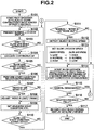
FIG. 2 is a flowchart showing the contents of shooting processing mainly in a slow live mode according to the embodiment; -
FIG. 3 is a view exemplifying a slow liveview start condition setting display window according to the embodiment; -
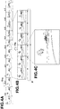
FIGS. 4A to 4C are views showing a basic sequence to select one still image data when "manual" is set as a slow liveview start condition according to the embodiment; and -
FIG. 5 is a view exemplifying a display window when "move out" is set as a slow liveview start condition according to the embodiment. - An embodiment of the present invention which is applied to a digital camera for shooting a still image will now be described with reference to the accompanying drawing.
-
FIG. 1 shows the circuit arrangement of adigital camera 10 according to the embodiment. Referring toFIG. 1 , the optical image of an object is formed via a lensoptical system 11 on the image sensing surface of aCCD 12 serving as a solid-state image sensor. - In the monitoring state, an image signal obtained from the image sensed by the
CCD 12 is sent to animage processing unit 13. Theimage processing unit 13 executes correlated double sampling, automatic gain control (AGC), and analog-to-digital conversion to convert the image signal into digital image data. Then, theimage processing unit 13 performs color processes including pixel interpolation and γ correction for the digital image data. Abuffer memory 14 temporarily holds the processed image data. - The image data held in the
buffer memory 14 is read out to theimage processing unit 13, sent to adisplay unit 15 via a system bus SB, and displayed as a monitor image. - A
control unit 16 comprehensively controls all these operations. Thecontrol unit 16 includes a CPU, and is connected to amain memory 17 andprogram memory 18. Themain memory 17 is formed from a synchronous DRAM (SDRAM). Theprogram memory 18 is formed from an electrically erasable nonvolatile memory which stores operation programs including a recording control program in a shooting mode (to be described later), permanent data, and the like. - The
control unit 16 reads out a necessary program, data, and the like from theprogram memory 18, and temporarily stores them in themain memory 17 upon expansion. During this, thecontrol unit 16 controls the overalldigital camera 10. - The
control unit 16 executes various control operations in correspondence with a key operation signal directly input from akey input unit 19. Thecontrol unit 16 is connected via the system bus SB to a lens opticalsystem driving unit 20,flash driving unit 21,CCD driver 22,memory card controller 23, built-inmemory 24, Universal Serial Bus (USB)interface 25, andaudio processing unit 26, in addition to theimage processing unit 13 anddisplay unit 15. - The
key input unit 19 includes a power key, shutter button, shooting mode key, playback mode key, menu key, cursor ("↑", "→", "↓", and "←") keys, set key, scene programming key, camera shake correction key, and face recognition function key. - The lens optical
system driving unit 20 receives a control signal from thecontrol unit 16 to control the rotation of a lens motor (M) 27. Thelens motor 27 is coupled to some of lenses, e.g., a focusing lens and zoom lens which configure the lensoptical system 11. As thelens motor 27 rotates, the focusing lens and zoom lens move along the optical axis. - In still image shooting, the
flash driving unit 21 receives a control signal from thecontrol unit 16 to turn on and drive aflash unit 28 in synchronism with the shooting timing. Theflash unit 28 includes a plurality of white high-intensity LEDs. - The
memory card controller 23 is connected to amemory card 29 via a card connector C. Thememory card 29 is a recording memory for image data that is detachably mounted in thedigital camera 10 and serves as the recording medium of thedigital camera 10. Thememory card 29 incorporates a flash memory serving as a nonvolatile memory electrically erasable for each block, and its driving circuit. - The built-in
memory 24 is an image recording memory permanently mounted in thedigital camera 10 separately from thedetachable memory card 29. The built-inmemory 24 similarly includes a flash memory serving as a nonvolatile memory electrically erasable for each block, and its driving circuit. - When the
memory card 29 is not mounted, the built-inmemory 24 functions as the recording medium of thedigital camera 10 to record image data and the like. When thememory card 29 is mounted, it is preferentially used. - Image data and the like can be arbitrarily copied and moved between the
memory card 29 and the built-inmemory 24. - The
USB interface 25 controls reception/transmission of data when connected to an external device (e.g., personal computer) of thedigital camera 10 via aUSB connector 30. - The
audio processing unit 26 includes a sound source circuit such as a PCM sound source. When recording audio data, theaudio processing unit 26 digitizes an audio signal input from amicrophone 31 arranged on the front surface of the housing of thedigital camera 10. Theaudio processing unit 26 compresses the digital data into a predetermined data file format such as moving picture experts group-4 advanced audio coding (AAC), creating an audio data file. Theaudio processing unit 26 sends the audio data file to thememory card 29 or built-inmemory 24. - When playing back audio data, the
audio processing unit 26 decompresses an audio data file read out from thememory card 29 or built-inmemory 24, and converts the decompressed audio data into an analog signal. Theaudio processing unit 26 drives aloudspeaker 32 attached to the rear surface of thedigital camera 10 to amplify the analog signal and output the amplified one. - The
image processing unit 13 includes anobject recognition unit 33 and compression/decompression processing unit 34. - The
object recognition unit 33 executes various kinds of recognition processes for an object in image data. For example, theobject recognition unit 33 performs face recognition by extracting an edge and face feature points from image data held in thebuffer memory 14 to create a face graph. Also, theobject recognition unit 33 calculates the moving amount between image frames of an object image as a motion vector. - When shooting an image in response to the shutter button operation of the
key input unit 19, the compression/decompression processing unit 34 greatly reduces the data amount of image data to be held in thebuffer memory 14 by performing data compression processing such as discrete cosine transformation (DCT) or Huffman coding for a predetermined data file format such as the Joint Photographic Experts Group (JPEG) format. - The
memory card 29 or built-inmemory 24 records an image data file created by the compression/decompression processing unit 34. - In the playback mode, the compression/
decompression processing unit 34 executes decompression processing to decompress image data read out from thememory card 29 or built-inmemory 24 in procedures reverse to those in recording, thereby obtaining image data of an original size. Then, thebuffer memory 14 holds the obtained image data. Thedisplay unit 15 executes playback display based on the image data held in thebuffer memory 14. - An operation in the embodiment will be explained.
- Any operation in the embodiment is executed when the
control unit 16 reads out an operation program, permanent data, and the like stored in theprogram memory 18 to expand them in themain memory 17. The operation program and the like are stored in theprogram memory 18 in the manufacture of thedigital camera 10, or installed and held in it after downloading them from an external device connected via theUSB interface 25 andUSB connector 30. - In the description of the operation in the embodiment, a shutter button, which is one of the keys of the
key input unit 19, is assumed to have two operation stokes. - In normal still image shooting, the
digital camera 10 performs an auto focus (AF) operation and auto-exposure (AE) operation to lock the focus position, aperture value, and shutter speed in response to a so-called half-stroke which is an operation stroke of the first stage to press the shutter button halfway with a slight resistance. - Then, the
digital camera 10 shoots a still image in response to a so-called full stroke which is an operation stroke of the second stage to press the shutter button to the bottom without temporarily canceling the shutter button operation from the half-stroke. Thememory card 29 or built-inmemory 24 records the shot image data. - The following operation example is directed not to the normal still image shooting but mainly to a shooting operation called slow live shooting.
- In slow live shooting, a plurality of still image data are shot continuously to hold a series of continuously shot images in the
buffer memory 14. Thedisplay unit 15 sequentially displays the still image data held in thebuffer memory 14 at a speed much lower than the shooting speed. When the user selects one image in accordance with the display timing, thememory card 29 records only the selected still image data. - The number of continuously shootable still image data is determined by the capacity of the
buffer memory 14, and an image size and image quality set at that time. The user can arbitrarily set a continuous shooting speed for a series of images within a predetermined range as the frame rate such as 60 frames/second. -
FIG. 2 shows the processing contents of slow live shooting. Thecontrol unit 16 executes this processing by expanding, in themain memory 17, an operation program read out from theprogram memory 18. - At the beginning of the processing, the
control unit 16 starts past shooting to cyclically store continuously shot image data of a predetermined past time (e.g., 1 second) in thebuffer memory 14 regardless of the shutter button operation of the key input unit 19 (step S101). - At the start of past shooting, new still image data are written in the
buffer memory 14. At the same time, the oldest still image data is erased. This operation is repetitively executed to always store continuously shot images of immediately past 1 second. - At the start of past shooting, the
display unit 15 starts normal liveview display to display in real time the contents of the latest still image data stored in the buffer memory 14 (step S102). - Based on whether the user has done a predetermined key operation to the
key input unit 19, thecontrol unit 16 determines whether he has designated a shift from the normal liveview display to a slow live mode (step S103). If NO in step S103, the sequence returns to the process in step S102. - The processes in steps S102 and S103 are repetitively executed in the above-described way during the normal liveview display until the user designates a shift to the slow live mode.
- If the user designates a shift to the slow live mode by a predetermined key operation to the
key input unit 19 using a combination of the menu key, cursor ("↑", "→", "↓", and "←") keys, and set key, thecontrol unit 16 detects it in step S103 and starts a continuous AF operation (step S104). - In the continuous AF operation, the AF operation is executed continuously without locking the in-focus position, so as to keep even a moving object in focus.
- In the continuous AF operation, the
control unit 16 determines whether the user has done a key operation to newly select a slow liveview start condition (step S105). - If the user has not done this key operation, the
control unit 16 determines whether a preset slow liveview start condition has already been established (step S110). - If no slow liveview start condition has been established, the sequence returns again to the process in step S104.
- While repetitively executing the processes in steps S104, S105, and S110, the sequence waits until the user performs a key operation to newly select a slow liveview start condition or the slow liveview start condition is established.
- If the user performs a key operation to newly select a slow liveview start condition, the
control unit 16 detects it in step S105, and the sequence shifts to a process to select a slow liveview start condition (step S106). -
FIG. 3 exemplifies a slow liveview start condition selection window displayed on thedisplay unit 15. InFIG. 3 , a plurality of conditions are prepared in advance, including "manual", "move in", "move out", "object stops", "object smiles", "person appears", and "panning". - "Manual" starts the slow liveview when the user presses the shutter button halfway.
-
FIGS. 4A to 4C show a basic sequence to select one still image data when "manual" is set as the slow liveview start condition. TheCCD 12 is assumed to have sensed a series of images, as represented inFIG. 4A . InFIG. 4A , "n-2", "n-1", ..., and "n+7" represent the frame numbers of image frames. - If the user presses the shutter button halfway at a timing Ths when the image frame "n-1" is shot, the
buffer memory 14 temporarily stores, as continuously shot images, image data of a predetermined number of frames starting from that of the image frame "n" immediately after the image frame "n-1. - For descriptive convenience, the
buffer memory 14 stores image data of a total of six frames up to the image frame "n+5". In practice, when the frame rate is 30 frames/second, thebuffer memory 14 stores image data of 30 frames, i.e., 1 second. - Simultaneously when the
buffer memory 14 stores image data of a predetermined number of frames, image data are read out from thebuffer memory 14 at a frame rate of, e.g., 1 frames/second much slower than an actual time, and sequentially displayed on thedisplay unit 15. - In
FIG. 4B , temporally successive image data of six frames are cyclically displayed as indicated by an arrow IV. - While cyclically displaying continuously short images of a predetermined number of frames, i.e., a predetermined time to allow the user to visually recognize the contents of each image, the sequence waits until he presses the shutter button fully subsequently to the half-stroke of the shutter button.
- In
FIG. 4B , the user presses the shutter button fully at a timing Thf when the image frame "n+2" is displayed. Thecontrol unit 16 determines that the user has selected still image data he wants by the full stroke of the shutter button. Then, the compression/decompression processing unit 34 compresses only the still image data of the image frame "n+2", as represented inFIG. 4C . Thememory card 29 or built-inmemory 24 records the compressed still image data. - In the basic operation of
FIGS. 4A to 4C , when the slow liveview starts in response to the half-stroke of the shutter button, still image data of the image frame "n" immediately after the timing Ths is positioned at the start of a series of continuously shot image data. In the embodiment, as described in step S101, the past shooting function runs to always store continuously shot images of a predetermined time in thebuffer memory 14. - For this reason, the
buffer memory 14 stores images of a total of 2 seconds, i.e., 1 second before the timing Ths when the shutter button was pressed halfway and 1 second after it. The slow liveview display also starts sequentially from image data of 1 second before the timing Ths when the shutter button was pressed halfway. - Referring back to
FIG. 3 , "(auto)" is added to the starts of the item names of the remaining start conditions "move in", "move out", "object stops", "object smiles", "person appears", and "panning". As is apparent from "(auto)", these conditions are set to automatically start the slow liveview upon a temporal change of an object in still image data obtained by shooting regardless of a key operation by the user. - The conditions "move in" and "move out" are to detect the contact of an object with a virtual frame in a monitor image displayed on the
display unit 15 when the object externally moves in the frame or internally moves out of it. Upon the detection, the slow liveview starts. -
FIG. 5 exemplifies a monitor image on thedisplay unit 15 at the "move out" setting. A rectangular frame FR is displayed slightly leftward from the center of thedisplay unit 15. The rectangular frame FR contains a bird (eagle) as an object OJ. For example, when the object OJ moves and comes into contact with the rectangular frame FR on thedisplay unit 15, the slow liveview starts automatically. - The condition "an object stops" is to calculate the motion vector between temporally adjacent image frames. When the total motion vector of the entire image becomes less than or equal to a predetermined value, it is determined that the object stops, and the slow liveview starts automatically.
- The condition "an object smiles" is to perform face recognition processing for image data using the
object recognition unit 33, thereby extracting a person's face and analyzing the facial expression. When the analysis result exceeds a preset index to determine that the expression is a smile, the slow liveview starts automatically. - The condition "person appears" is to perform face recognition processing for image data using the
object recognition unit 33. When a person's face, which has not been extracted before, is extracted, the slow liveview starts automatically. - The condition "panning" is to calculate the motion vector between temporally adjacent image frames at, e.g., each of the center and periphery of image data. When the magnitude of the motion vector at the periphery exceeds a preset index much more than that of the motion vector at the center, the slow liveview starts automatically.
- If the slow liveview start condition selection processing ends in step S106 of
FIG. 2 , thecontrol unit 16 determines whether the selected start condition is either "move in" or "move out" (step S107). - Only when the
control unit 16 determines that the selected start condition is "move in" or "move out", the size and position of the frame FR displayed on thedisplay unit 15 are adjusted (step S108). - After that, the
control unit 16 sets all the selected slow liveview start condition, the adjustment contents of the frame FR especially for the start condition "move in" or "move out", and the like (step S109). - The sequence advances to step S110 to determine whether the newly set slow liveview start condition has been established. If no slow liveview start condition has been established, the sequence returns again to the process in step S104.
- The processes in steps S104, S105, and S110 are repetitively executed. The sequence waits until the user performs a key operation to newly select a slow liveview start condition or the slow liveview start condition is established. If the set slow liveview start condition is established, the
control unit 16 detects it in step S110. - In this case, the
control unit 16 determines whether the set slow liveview start condition is "manual", "move in", or "move out" (step S111). - If the
control unit 16 determines that the set start condition is "manual", "move in", or "move out", it calculates the object moving speed as the magnitude (number of pixels) of a motion vector between current image data and image data which has been shot immediately before the current image data and is stored in the buffer memory 14 (step S112). - That is, when the
control unit 16 determines that the set start condition is "manual", it calculates the object moving speed by comparing an image frame obtained when the user pressed the shutter button halfway, and an image frame shot immediately before it. - When the
control unit 16 determines that the set start condition is "move in" or "move out", it calculates the object moving speed by comparing an image frame shot when the contact of the object with the frame was detected, and an image frame shot immediately before it. - The
control unit 16 sets the slow liveview speed, e.g., the display time per image frame from the calculated object moving speed (step S113). - This calculation uses preset moving speed thresholds PX1 and PX2 (PX1 < PX2). When an object moving speed PXn is lower than the threshold PX1, it is determined that the object moves slowly (= moving distance in image data is short [number of pixels is small]. Thus, the slow liveview speed is set as high as, e.g., 0.5 seconds per image frame.
- When the object moving speed PXn is greater than or equal to the threshold PX1 and lower than the threshold PX2, it is determined that the object moves at a normal speed, and the slow liveview speed is set to a normal speed of, e.g., 1 second per image frame.
- When the object moving speed PXn is greater than or equal to the threshold PX2, it is determined that the object moves quickly (= moving distance in image data is long [number of pixels is large]. Hence, the slow liveview speed is set as low as, e.g., 2 sec per image frame.
- Then, the slow liveview starts using a series of still image data stored in the
buffer memory 14. At the set speed, thedisplay unit 15 cyclically displays still image data of a total of 2 seconds, i.e., 1 second before the timing when the start condition was established and 1 second after it (step S114). - At this time, the
display unit 15 provides on screen display (OSD) of a guide message such as - "Cancel → Menu/select → Full Stroke of Shutter" The OSD prompts the user to perform a key operation to select or cancel an image.
- While executing the slow liveview display, the
control unit 16 determines whether the user has done a cancel key operation using the key input unit 19 (step S115). - If the user has not performed the cancel key operation, the
control unit 16 determines whether the user has pressed the shutter button fully to select an image (step S116). - If the user has not pressed the shutter button fully to select an image, either, the sequence returns to step S114.
- While repetitively executing the processes in steps S114 to S116 to present the slow liveview display, the sequence waits until the user performs a key operation to cancel or select an image.
- If the user performs a cancel key operation during the slow liveview display, the
control unit 16 detects it in step S115, and the sequence returns again to the processes from step S102 in preparation for the next shooting. - If the user presses the shutter button fully to select an image during the slow liveview display, the
control unit 16 detects it in step S116, and selects still image data displayed at this time in the slow liveview. The compression/decompression processing unit 34 compresses the selected still image data, and thememory card 29 or built-inmemory 24 records the compressed still image data (step S117). Then, a series of slow live shooting operations ends. - As described above, the embodiment can easily adjust the capturing start timing of a series of still image data having a limited time width without missing the shooting timing the user wants even for a quickly moving object.
- Especially in the embodiment, a temporal change of an object in a series of still image data obtained by shooting is detected to start the slow liveview. The embodiment can therefore set a capturing start timing directly linked to a still image shooting timing the user wants.
- In this case, the slow liveview starts while the object is always in focus by executing the continuous AF operation. This can eliminate an AF time lag at the start of the slow liveview, achieving a smoother operation.
- As described as "move in" and "move out" in the embodiment, entrance of an object image into a predetermined area in still image data and exit of an object image from a predetermined area can be set as slow liveview start conditions. This allows starting the slow liveview at an appropriate timing even when shooting an object which moves at high speed so that it is difficult to keep capturing the object in the shooting range.
- In slow live shooting, the display speed of the slow liveview is controlled in accordance with the object moving speed. A proper display speed can be set easily and automatically, and the next shooting can be prepared for quickly.
- Since the stop of an object image can be set as a slow liveview start condition, even an object whose motion is hardly predicted can be easily coped with.
- Further, a combination of face recognition and expression detection of an object, which have become fully practical these days, can be set as a slow liveview start condition. When the user wants to shoot the smile of a specific person, a still image he wants can be reliably captured though the apparatus automatically selects the shooting timing.
- The appearance of a person's face in the shooting range can be set as a slow liveview start condition. Even an object whose motion is hardly predicted can be easily coped with, canceling an operation delay when the object suddenly enters the shooting range.
- In addition, the embodiment executes past shooting to capture even still images of a predetermined time immediately before the start of the slow liveview. Even if the slow live shooting start timing delays, an image the user wants can be shot without missing the desired timing.
- In the embodiment, a temporal change of an object in a series of still image data obtained by shooting is detected to start the slow liveview. However, the present invention is not exclusive to this. For example, it can also be set as a predetermined state a case in which a temporal change of an acoustic characteristic of a sound acquired using the
microphone 31 andaudio processing unit 26, e.g., a relative sound pressure has reached a predetermined threshold, or a case in which a voice of a predetermined frequency band such as one or a plurality of bands is detected. - For example, a pistol sound at the start of a footrace is set as a slow live shooting start timing. In this way, the present invention is applied to a wider range of purposes.
- In the embodiment, the present invention is applied to a digital camera. However, the present invention is not limited to this, and is also applicable to a video movie camera capable of shooting a still image, a cell phone having a camera function, a personal digital assistant (PDA), or a compact electronic device such as a mobile personal computer equipped with a web camera.
- According to a further embodiment, an image sensing apparatus is provided. The image sensing apparatus comprises an image sensing unit which shoots an object image to sequentially generate still image data; a holding unit which accumulates and holds a plurality of still image data obtained by the image sensing unit; a display unit which displays the still image data held in the holding unit; a setting unit which sets a predetermined state as a start timing of shooting by the image sensing unit; a determination unit which determines whether the predetermined state set by the setting unit has been obtained; a shooting control unit which causes the image sensing unit to start shooting when the determination unit determines that the predetermined state has been obtained; a display control unit which causes the display unit to sequentially display, at a display speed lower than an actual time, still image data held in the holding unit in shooting started by the shooting control unit; a selection unit which selects one of a plurality of image data displayed on the display unit; and a recording unit which records the image data selected by the selection unit.
- Preferably, the setting unit sets, as the predetermined state, a temporal change of an object in still image data obtained by the image sensing unit.
- Preferably, the image sensing unit has an automatic focusing function of automatically focusing on an object image, and the shooting control unit starts the automatic focusing function of the image sensing unit in accordance with a setting by the setting unit.
- Preferably, the setting unit sets, as the predetermined state, either of entrance of an object image into a predetermined area in still image data obtained by the image sensing unit, and exit of an object image from a predetermined area.
- Preferably, the image sensing apparatus further comprises a speed detection unit which detects either of a speed of the entrance of the object image into the predetermined area in the still image data and a speed of the exit of the object image from the predetermined area, and characterized in that the display control unit variably controls, in accordance with the speed of the object image detected by the speed detection unit, the display speed used when the display unit displays still image data held in the holding unit.
- Preferably, the setting unit sets, as the predetermined state, a stop of an object image for a predetermined continuous time in still image data obtained by the image sensing unit. Preferably, the setting unit sets, as the predetermined state, detection of a predetermined expression of an object image capable of face recognition in still image data obtained by the image sensing unit.
- Preferably, the setting unit sets, as the predetermined state, appearance of an object image capable of face recognition in still image data obtained by the image sensing unit.
- Preferably, the holding unit cyclically holds, in a partial area for only a first time, a plurality of still image data obtained by the image sensing unit; and when the determination unit determines that the predetermined state has been obtained, the shooting control unit causes the holding unit to keep holding, in a remaining area of the holding unit, a plurality of still image data obtained by shooting by the image sensing unit together with the plurality of still image data held in the partial area of the holding unit for only the first time.
- Preferably, the image sensing apparatus further comprises an audio input unit which inputs a sound, and characterized in that the setting unit sets, as the predetermined state, a temporal change of an acoustic characteristic of a sound obtained by the audio input unit.
- According to a further embodiment, a computer-readable storage medium is provided. The storage medium stores a program which is executed by a computer incorporated in an image sensing apparatus having an image sensing unit which shoots an object image to sequentially generate still image data, a holding unit which accumulates and holds a plurality of still image data obtained by the image sensing unit, and a display unit which displays the still image data held in the holding unit, the program causing the image sensing apparatus to function as (i) setting means for setting a predetermined state as a start timing of shooting by the image sensing unit, (ii) determination means for determining whether the predetermined state set by the setting means has been obtained, (iii) shooting control means for causing the image sensing unit to start shooting when the determination means determines that the predetermined state has been obtained, (iv) display control means for causing the display unit to sequentially display, at a display speed lower than an actual time, still image data held in the holding unit in shooting started by the shooting control means, (v) selection means for selecting one of a plurality of image data displayed on the display unit, and (vi) recording means for recording the image data selected by the selection means.
Claims (3)
- An image displaying apparatus comprising:a holding unit (14) which holds a plurality of still image data sequentially generated by an image sensing unit (11 - 13); anda display unit (15) which sequentially displays the still image data held by the holding unit (14) with a frame (FR),characterized bya first detection unit (16 - 18) which detects contact of an object with the frame, the object included in the still image data sequentially displayed by the display unit (15);a second detection unit (16 - 18) which detects a moving speed of the object when the contact is detected by the first detection unit (16 - 18);a display speed control unit (16 - 18) which controls display speed at which the display unit (15) sequentially displays still image data slower than a continuous shooting speed of the image sensing unit (11 - 13), and to a speed based on the object moving speed detected by the second detection unit (16 - 18);a third detection unit (19) which detects external operation when the still image data is being displayed sequentially at the display speed controlled by the display speed control unit (16 - 18); anda recording unit (29) which records the still image data being displayed on the display unit (15) when the external operation is detected by the third detection unit (19).
- An image displaying method in an image displaying apparatus comprising a display unit (15), the method comprising:a holding step of holding a plurality of still image data sequentially generated by an image sensing unit (11 - 13) in a first memory (14); anda displaying step of causing the display unit (15) to sequentially display the still image data held in the holding step with a frame,characterized bya first detecting step of detecting contact of an object with the frame, the object included in the still image data sequentially displayed in the displaying step;a second detecting step of detecting a moving speed of the object when the contact is detected in the first detecting step;a display speed controlling step of controlling display speed at which the still image data is sequentially displayed in the displaying step slower than the continuous shooting speed in the image sensing step, and to a speed based on the object moving speed detected in the second detecting step;a third detecting step of detecting external operation when the still image data is being displayed sequentially at the display speed controlled in the display speed controlling step; anda recording step of recording the still image data being displayed on the display unit (15) in a second memory when the external operation is detected in the third detecting step.
- A computer readable storage medium storing a program which is executed by a computer incorporated in an image displaying apparatus having a holding unit (14) which holds a plurality of still image data generated sequentially by an image sensing unit (11 - 13), and a display unit (15) which sequentially displays the still image data held by the holding unit (14) with a frame, the program
characterized by causing the image displaying apparatus to function as
first detecting means (16 - 18) for detecting contact of an object with the frame, the object included in the still image data sequentially displayed by the display unit (15);
second detecting means (16 - 18) for detecting a moving speed of the object when the contact is detected by the first detecting means (16 - 18);
display speed controlling means (16 - 18) for controlling display speed at which the still image data is displayed sequentially by the display unit (15) slower than the continuous shooting speed in the image sensing unit (11 - 13), and to a speed based on the object moving speed detected by the second detecting means (16 - 18);
third detecting means (19) for detecting external operation when the still image data is being displayed sequentially at the display speed controlled by the display speed controlling means (16 - 18); and
recording means (29) for recording the still image data being displayed on the display unit (15) when the external operation is detected by the third detecting means (19).
Applications Claiming Priority (2)
| Application Number | Priority Date | Filing Date | Title |
|---|---|---|---|
| JP2008170421A JP4730402B2 (en) | 2008-06-30 | 2008-06-30 | Imaging apparatus, imaging control method, and program |
| EP09163536.7A EP2141913B1 (en) | 2008-06-30 | 2009-06-24 | Image sensing apparatus and storage medium |
Related Parent Applications (2)
| Application Number | Title | Priority Date | Filing Date |
|---|---|---|---|
| EP09163536.7A Division-Into EP2141913B1 (en) | 2008-06-30 | 2009-06-24 | Image sensing apparatus and storage medium |
| EP09163536.7A Division EP2141913B1 (en) | 2008-06-30 | 2009-06-24 | Image sensing apparatus and storage medium |
Publications (2)
| Publication Number | Publication Date |
|---|---|
| EP3174284A1 true EP3174284A1 (en) | 2017-05-31 |
| EP3174284B1 EP3174284B1 (en) | 2022-06-01 |
Family
ID=41137462
Family Applications (2)
| Application Number | Title | Priority Date | Filing Date |
|---|---|---|---|
| EP09163536.7A Active EP2141913B1 (en) | 2008-06-30 | 2009-06-24 | Image sensing apparatus and storage medium |
| EP16199324.1A Active EP3174284B1 (en) | 2008-06-30 | 2009-06-24 | Image sensing apparatus and storage medium |
Family Applications Before (1)
| Application Number | Title | Priority Date | Filing Date |
|---|---|---|---|
| EP09163536.7A Active EP2141913B1 (en) | 2008-06-30 | 2009-06-24 | Image sensing apparatus and storage medium |
Country Status (6)
| Country | Link |
|---|---|
| US (2) | US8294779B2 (en) |
| EP (2) | EP2141913B1 (en) |
| JP (1) | JP4730402B2 (en) |
| KR (2) | KR20100003240A (en) |
| CN (1) | CN101621617B (en) |
| TW (1) | TWI458352B (en) |
Families Citing this family (20)
| Publication number | Priority date | Publication date | Assignee | Title |
|---|---|---|---|---|
| JP4730402B2 (en) * | 2008-06-30 | 2011-07-20 | カシオ計算機株式会社 | Imaging apparatus, imaging control method, and program |
| JP5821019B2 (en) | 2010-03-09 | 2015-11-24 | パナソニックIpマネジメント株式会社 | Imaging apparatus and information detection method |
| JP5616819B2 (en) * | 2010-03-10 | 2014-10-29 | 富士フイルム株式会社 | Shooting assist method, program thereof, recording medium thereof, shooting apparatus and shooting system |
| JP5054175B2 (en) | 2010-09-08 | 2012-10-24 | キヤノン株式会社 | Imaging apparatus and control method thereof, imaging control apparatus, and imaging control method |
| JP5783737B2 (en) * | 2011-02-02 | 2015-09-24 | キヤノン株式会社 | Image pickup apparatus and moving image recording apparatus control method |
| JP5862148B2 (en) * | 2011-07-25 | 2016-02-16 | 株式会社ニコン | Camera body, camera system, and program |
| KR101814604B1 (en) * | 2011-08-30 | 2018-01-04 | 삼성전자주식회사 | Digital photographing apparatus and control method thereof |
| US9041825B2 (en) * | 2011-10-12 | 2015-05-26 | Olympus Corporation | Image processing apparatus |
| JP6061715B2 (en) * | 2013-02-13 | 2017-01-18 | キヤノン株式会社 | Imaging apparatus, control method thereof, and program |
| EP2819395B1 (en) * | 2013-06-27 | 2015-08-12 | Axis AB | Method and apparatus for setting a camera exposure time |
| US20150001762A1 (en) * | 2013-06-27 | 2015-01-01 | Alberto Daniel Lacaze | Method for Deployable Rapid On-Site Manufacturing Using 3D Printing in Combination with Vacuum Metallization |
| SG2013075338A (en) * | 2013-10-08 | 2015-05-28 | K One Ind Pte Ltd | Set meal preparation system |
| CN104580874B (en) * | 2013-10-22 | 2019-12-13 | 中兴通讯股份有限公司 | Camera device and method for taking pictures thereof |
| JP2017011435A (en) * | 2015-06-19 | 2017-01-12 | キヤノン株式会社 | Imaging apparatus and control method thereof |
| JP6498051B2 (en) * | 2015-06-19 | 2019-04-10 | キヤノン株式会社 | Imaging apparatus and control method thereof |
| US9894259B2 (en) * | 2015-06-29 | 2018-02-13 | Lenovo Enterprise Solutions (Singapore) Pte. Ltd. | Movable image capture devices and methods for capture of images from behind a display screen |
| JP6928663B2 (en) * | 2017-09-20 | 2021-09-01 | 富士フイルム株式会社 | Imaging control device, imaging device, imaging control method, and imaging control program |
| CN109348135A (en) * | 2018-11-21 | 2019-02-15 | Oppo广东移动通信有限公司 | Photographing method and device, storage medium and terminal equipment |
| CN112532903B (en) * | 2019-09-18 | 2022-08-09 | 华为技术有限公司 | Intelligent video recording method, electronic equipment and computer readable storage medium |
| US11587276B2 (en) | 2019-12-03 | 2023-02-21 | Disney Enterprises, Inc. | Data-driven extraction and composition of secondary dynamics in facial performance capture |
Citations (5)
| Publication number | Priority date | Publication date | Assignee | Title |
|---|---|---|---|---|
| US20050231631A1 (en) * | 1999-09-14 | 2005-10-20 | Takao Miyazaki | Image pickup apparatus for producing a desired frame of image signals |
| JP2006140892A (en) * | 2004-11-15 | 2006-06-01 | Konica Minolta Photo Imaging Inc | Electronic still camera |
| JP2006253768A (en) | 2005-03-08 | 2006-09-21 | Uniden Corp | Digital camera |
| JP2007258862A (en) * | 2006-03-22 | 2007-10-04 | Seiko Epson Corp | Standby shooting with standby shooting under preset shooting conditions |
| US20080129854A1 (en) * | 2006-11-14 | 2008-06-05 | Casio Computer Co., Ltd. | Imaging appartus, imaging method and program thereof |
Family Cites Families (14)
| Publication number | Priority date | Publication date | Assignee | Title |
|---|---|---|---|---|
| JP3299741B2 (en) * | 1990-03-14 | 2002-07-08 | オリンパス光学工業株式会社 | Automatic shooting system |
| JP3398510B2 (en) * | 1995-03-20 | 2003-04-21 | 富士通株式会社 | Object detection system |
| JPH11221309A (en) | 1998-02-06 | 1999-08-17 | Flex:Kk | Form checker |
| JP2002042139A (en) | 2000-07-25 | 2002-02-08 | Hitachi Ltd | Image recognition method and image display device |
| JP4359743B2 (en) * | 2001-05-25 | 2009-11-04 | 富士フイルム株式会社 | Camera control method and camera |
| JP2004350187A (en) * | 2003-05-26 | 2004-12-09 | Nikon Gijutsu Kobo:Kk | Digital camera |
| JP2005094133A (en) * | 2003-09-12 | 2005-04-07 | Fuji Photo Film Co Ltd | Photographing apparatus |
| JP4134004B2 (en) | 2004-11-15 | 2008-08-13 | Tdk株式会社 | High frequency module |
| JP4639869B2 (en) * | 2005-03-14 | 2011-02-23 | オムロン株式会社 | Imaging apparatus and timer photographing method |
| JP2006270868A (en) * | 2005-03-25 | 2006-10-05 | Olympus Imaging Corp | Imaging apparatus and image recording method |
| JP2007172035A (en) * | 2005-12-19 | 2007-07-05 | Fujitsu Ten Ltd | Onboard image recognition device, onboard imaging device, onboard imaging controller, warning processor, image recognition method, imaging method and imaging control method |
| JP4727534B2 (en) * | 2006-08-28 | 2011-07-20 | 富士フイルム株式会社 | Imaging device |
| JP4835356B2 (en) | 2006-09-28 | 2011-12-14 | カシオ計算機株式会社 | Imaging apparatus, imaging control program, and imaging control method |
| JP4730402B2 (en) * | 2008-06-30 | 2011-07-20 | カシオ計算機株式会社 | Imaging apparatus, imaging control method, and program |
-
2008
- 2008-06-30 JP JP2008170421A patent/JP4730402B2/en not_active Expired - Fee Related
-
2009
- 2009-06-10 US US12/481,667 patent/US8294779B2/en not_active Expired - Fee Related
- 2009-06-16 CN CN2009101493382A patent/CN101621617B/en active Active
- 2009-06-24 EP EP09163536.7A patent/EP2141913B1/en active Active
- 2009-06-24 EP EP16199324.1A patent/EP3174284B1/en active Active
- 2009-06-29 TW TW098121800A patent/TWI458352B/en not_active IP Right Cessation
- 2009-06-30 KR KR1020090058884A patent/KR20100003240A/en not_active Ceased
-
2011
- 2011-07-07 KR KR1020110067252A patent/KR101075826B1/en not_active Expired - Fee Related
-
2012
- 2012-09-13 US US13/614,487 patent/US8411158B2/en not_active Expired - Fee Related
Patent Citations (5)
| Publication number | Priority date | Publication date | Assignee | Title |
|---|---|---|---|---|
| US20050231631A1 (en) * | 1999-09-14 | 2005-10-20 | Takao Miyazaki | Image pickup apparatus for producing a desired frame of image signals |
| JP2006140892A (en) * | 2004-11-15 | 2006-06-01 | Konica Minolta Photo Imaging Inc | Electronic still camera |
| JP2006253768A (en) | 2005-03-08 | 2006-09-21 | Uniden Corp | Digital camera |
| JP2007258862A (en) * | 2006-03-22 | 2007-10-04 | Seiko Epson Corp | Standby shooting with standby shooting under preset shooting conditions |
| US20080129854A1 (en) * | 2006-11-14 | 2008-06-05 | Casio Computer Co., Ltd. | Imaging appartus, imaging method and program thereof |
Also Published As
| Publication number | Publication date |
|---|---|
| EP2141913A3 (en) | 2010-07-14 |
| US20090322895A1 (en) | 2009-12-31 |
| JP2010011289A (en) | 2010-01-14 |
| KR101075826B1 (en) | 2011-10-25 |
| JP4730402B2 (en) | 2011-07-20 |
| EP2141913B1 (en) | 2017-01-11 |
| HK1136727A1 (en) | 2010-07-02 |
| US8294779B2 (en) | 2012-10-23 |
| KR20110089239A (en) | 2011-08-05 |
| EP3174284B1 (en) | 2022-06-01 |
| CN101621617A (en) | 2010-01-06 |
| KR20100003240A (en) | 2010-01-07 |
| EP2141913A2 (en) | 2010-01-06 |
| TWI458352B (en) | 2014-10-21 |
| US8411158B2 (en) | 2013-04-02 |
| US20130010171A1 (en) | 2013-01-10 |
| CN101621617B (en) | 2013-01-09 |
| TW201008277A (en) | 2010-02-16 |
Similar Documents
| Publication | Publication Date | Title |
|---|---|---|
| EP3174284B1 (en) | Image sensing apparatus and storage medium | |
| KR101578600B1 (en) | Image processing device, image processing method, and computer readable storage medium | |
| JP4873031B2 (en) | Imaging apparatus, imaging method, and program | |
| US20060050997A1 (en) | Camera device with movie capture function | |
| JP2011049822A (en) | Display controller and display control program | |
| KR101433121B1 (en) | Image processing device for generating composite image having predetermined aspect ratio | |
| US20090207278A1 (en) | Image pick-up apparatus, image data processing apparatus, and recording medium | |
| JP5338373B2 (en) | Imaging device | |
| JP2013081101A (en) | Image processing apparatus, imaging apparatus, and program | |
| JP5168375B2 (en) | Imaging apparatus, imaging method, and program | |
| JP2007318292A (en) | Motion vector detection apparatus and program thereof | |
| JP5625325B2 (en) | Image data recording apparatus and image data recording program | |
| JP2007189295A (en) | Imaging apparatus and program thereof | |
| JP5304833B2 (en) | Imaging apparatus, imaging control method, and program | |
| JP5105298B2 (en) | Imaging apparatus and program thereof | |
| JP2005109915A (en) | Image recording apparatus, image recording method, and camera using the same | |
| JP2014120926A (en) | Imaging apparatus | |
| HK1136727B (en) | Image sensing apparatus and image control method | |
| JP5287636B2 (en) | Image data recording apparatus and image data recording program | |
| JP5945946B2 (en) | Imaging apparatus, program, and imaging method | |
| JP2011135286A (en) | Image recording apparatus and program | |
| HK1168486A (en) | Image capturing apparatus of continuously capturing object | |
| HK1171594A (en) | Motion image processing apparatus and motion image processing method for processing motion image data | |
| JP2015230448A (en) | Imaging device, control method therefor, and control program |
Legal Events
| Date | Code | Title | Description |
|---|---|---|---|
| PUAI | Public reference made under article 153(3) epc to a published international application that has entered the european phase |
Free format text: ORIGINAL CODE: 0009012 |
|
| STAA | Information on the status of an ep patent application or granted ep patent |
Free format text: STATUS: THE APPLICATION HAS BEEN PUBLISHED |
|
| AC | Divisional application: reference to earlier application |
Ref document number: 2141913 Country of ref document: EP Kind code of ref document: P |
|
| AK | Designated contracting states |
Kind code of ref document: A1 Designated state(s): AT BE BG CH CY CZ DE DK EE ES FI FR GB GR HR HU IE IS IT LI LT LU LV MC MK MT NL NO PL PT RO SE SI SK TR |
|
| STAA | Information on the status of an ep patent application or granted ep patent |
Free format text: STATUS: REQUEST FOR EXAMINATION WAS MADE |
|
| 17P | Request for examination filed |
Effective date: 20170721 |
|
| RBV | Designated contracting states (corrected) |
Designated state(s): AT BE BG CH CY CZ DE DK EE ES FI FR GB GR HR HU IE IS IT LI LT LU LV MC MK MT NL NO PL PT RO SE SI SK TR |
|
| STAA | Information on the status of an ep patent application or granted ep patent |
Free format text: STATUS: EXAMINATION IS IN PROGRESS |
|
| 17Q | First examination report despatched |
Effective date: 20190627 |
|
| RAP3 | Party data changed (applicant data changed or rights of an application transferred) |
Owner name: BEIJING XIAOMI MOBILE SOFTWARE CO., LTD. |
|
| GRAP | Despatch of communication of intention to grant a patent |
Free format text: ORIGINAL CODE: EPIDOSNIGR1 |
|
| STAA | Information on the status of an ep patent application or granted ep patent |
Free format text: STATUS: GRANT OF PATENT IS INTENDED |
|
| RIC1 | Information provided on ipc code assigned before grant |
Ipc: H04N 101/00 20060101ALI20211213BHEP Ipc: H04N 1/21 20060101ALI20211213BHEP Ipc: H04N 5/262 20060101ALI20211213BHEP Ipc: H04N 5/232 20060101AFI20211213BHEP |
|
| INTG | Intention to grant announced |
Effective date: 20220110 |
|
| GRAS | Grant fee paid |
Free format text: ORIGINAL CODE: EPIDOSNIGR3 |
|
| GRAA | (expected) grant |
Free format text: ORIGINAL CODE: 0009210 |
|
| STAA | Information on the status of an ep patent application or granted ep patent |
Free format text: STATUS: THE PATENT HAS BEEN GRANTED |
|
| AC | Divisional application: reference to earlier application |
Ref document number: 2141913 Country of ref document: EP Kind code of ref document: P |
|
| AK | Designated contracting states |
Kind code of ref document: B1 Designated state(s): AT BE BG CH CY CZ DE DK EE ES FI FR GB GR HR HU IE IS IT LI LT LU LV MC MK MT NL NO PL PT RO SE SI SK TR |
|
| REG | Reference to a national code |
Ref country code: GB Ref legal event code: FG4D |
|
| REG | Reference to a national code |
Ref country code: AT Ref legal event code: REF Ref document number: 1496192 Country of ref document: AT Kind code of ref document: T Effective date: 20220615 Ref country code: CH Ref legal event code: EP |
|
| REG | Reference to a national code |
Ref country code: IE Ref legal event code: FG4D |
|
| REG | Reference to a national code |
Ref country code: DE Ref legal event code: R096 Ref document number: 602009064464 Country of ref document: DE |
|
| REG | Reference to a national code |
Ref country code: FR Ref legal event code: PLFP Year of fee payment: 14 |
|
| REG | Reference to a national code |
Ref country code: LT Ref legal event code: MG9D |
|
| REG | Reference to a national code |
Ref country code: NL Ref legal event code: MP Effective date: 20220601 |
|
| PG25 | Lapsed in a contracting state [announced via postgrant information from national office to epo] |
Ref country code: SE Free format text: LAPSE BECAUSE OF FAILURE TO SUBMIT A TRANSLATION OF THE DESCRIPTION OR TO PAY THE FEE WITHIN THE PRESCRIBED TIME-LIMIT Effective date: 20220601 Ref country code: NO Free format text: LAPSE BECAUSE OF FAILURE TO SUBMIT A TRANSLATION OF THE DESCRIPTION OR TO PAY THE FEE WITHIN THE PRESCRIBED TIME-LIMIT Effective date: 20220901 Ref country code: LT Free format text: LAPSE BECAUSE OF FAILURE TO SUBMIT A TRANSLATION OF THE DESCRIPTION OR TO PAY THE FEE WITHIN THE PRESCRIBED TIME-LIMIT Effective date: 20220601 Ref country code: HR Free format text: LAPSE BECAUSE OF FAILURE TO SUBMIT A TRANSLATION OF THE DESCRIPTION OR TO PAY THE FEE WITHIN THE PRESCRIBED TIME-LIMIT Effective date: 20220601 Ref country code: GR Free format text: LAPSE BECAUSE OF FAILURE TO SUBMIT A TRANSLATION OF THE DESCRIPTION OR TO PAY THE FEE WITHIN THE PRESCRIBED TIME-LIMIT Effective date: 20220902 Ref country code: FI Free format text: LAPSE BECAUSE OF FAILURE TO SUBMIT A TRANSLATION OF THE DESCRIPTION OR TO PAY THE FEE WITHIN THE PRESCRIBED TIME-LIMIT Effective date: 20220601 Ref country code: ES Free format text: LAPSE BECAUSE OF FAILURE TO SUBMIT A TRANSLATION OF THE DESCRIPTION OR TO PAY THE FEE WITHIN THE PRESCRIBED TIME-LIMIT Effective date: 20220601 Ref country code: BG Free format text: LAPSE BECAUSE OF FAILURE TO SUBMIT A TRANSLATION OF THE DESCRIPTION OR TO PAY THE FEE WITHIN THE PRESCRIBED TIME-LIMIT Effective date: 20220901 |
|
| REG | Reference to a national code |
Ref country code: AT Ref legal event code: MK05 Ref document number: 1496192 Country of ref document: AT Kind code of ref document: T Effective date: 20220601 |
|
| REG | Reference to a national code |
Ref country code: DE Ref legal event code: R079 Ref document number: 602009064464 Country of ref document: DE Free format text: PREVIOUS MAIN CLASS: H04N0005232000 Ipc: H04N0023600000 |
|
| PG25 | Lapsed in a contracting state [announced via postgrant information from national office to epo] |
Ref country code: PL Free format text: LAPSE BECAUSE OF FAILURE TO SUBMIT A TRANSLATION OF THE DESCRIPTION OR TO PAY THE FEE WITHIN THE PRESCRIBED TIME-LIMIT Effective date: 20220601 Ref country code: LV Free format text: LAPSE BECAUSE OF FAILURE TO SUBMIT A TRANSLATION OF THE DESCRIPTION OR TO PAY THE FEE WITHIN THE PRESCRIBED TIME-LIMIT Effective date: 20220601 |
|
| PG25 | Lapsed in a contracting state [announced via postgrant information from national office to epo] |
Ref country code: NL Free format text: LAPSE BECAUSE OF FAILURE TO SUBMIT A TRANSLATION OF THE DESCRIPTION OR TO PAY THE FEE WITHIN THE PRESCRIBED TIME-LIMIT Effective date: 20220601 |
|
| PG25 | Lapsed in a contracting state [announced via postgrant information from national office to epo] |
Ref country code: SK Free format text: LAPSE BECAUSE OF FAILURE TO SUBMIT A TRANSLATION OF THE DESCRIPTION OR TO PAY THE FEE WITHIN THE PRESCRIBED TIME-LIMIT Effective date: 20220601 Ref country code: RO Free format text: LAPSE BECAUSE OF FAILURE TO SUBMIT A TRANSLATION OF THE DESCRIPTION OR TO PAY THE FEE WITHIN THE PRESCRIBED TIME-LIMIT Effective date: 20220601 Ref country code: PT Free format text: LAPSE BECAUSE OF FAILURE TO SUBMIT A TRANSLATION OF THE DESCRIPTION OR TO PAY THE FEE WITHIN THE PRESCRIBED TIME-LIMIT Effective date: 20221003 Ref country code: EE Free format text: LAPSE BECAUSE OF FAILURE TO SUBMIT A TRANSLATION OF THE DESCRIPTION OR TO PAY THE FEE WITHIN THE PRESCRIBED TIME-LIMIT Effective date: 20220601 Ref country code: CZ Free format text: LAPSE BECAUSE OF FAILURE TO SUBMIT A TRANSLATION OF THE DESCRIPTION OR TO PAY THE FEE WITHIN THE PRESCRIBED TIME-LIMIT Effective date: 20220601 Ref country code: AT Free format text: LAPSE BECAUSE OF FAILURE TO SUBMIT A TRANSLATION OF THE DESCRIPTION OR TO PAY THE FEE WITHIN THE PRESCRIBED TIME-LIMIT Effective date: 20220601 |
|
| REG | Reference to a national code |
Ref country code: CH Ref legal event code: PL |
|
| REG | Reference to a national code |
Ref country code: BE Ref legal event code: MM Effective date: 20220630 |
|
| PG25 | Lapsed in a contracting state [announced via postgrant information from national office to epo] |
Ref country code: MC Free format text: LAPSE BECAUSE OF FAILURE TO SUBMIT A TRANSLATION OF THE DESCRIPTION OR TO PAY THE FEE WITHIN THE PRESCRIBED TIME-LIMIT Effective date: 20220601 Ref country code: IS Free format text: LAPSE BECAUSE OF FAILURE TO SUBMIT A TRANSLATION OF THE DESCRIPTION OR TO PAY THE FEE WITHIN THE PRESCRIBED TIME-LIMIT Effective date: 20221001 |
|
| REG | Reference to a national code |
Ref country code: DE Ref legal event code: R097 Ref document number: 602009064464 Country of ref document: DE |
|
| PLBE | No opposition filed within time limit |
Free format text: ORIGINAL CODE: 0009261 |
|
| STAA | Information on the status of an ep patent application or granted ep patent |
Free format text: STATUS: NO OPPOSITION FILED WITHIN TIME LIMIT |
|
| PG25 | Lapsed in a contracting state [announced via postgrant information from national office to epo] |
Ref country code: LU Free format text: LAPSE BECAUSE OF NON-PAYMENT OF DUE FEES Effective date: 20220624 Ref country code: LI Free format text: LAPSE BECAUSE OF NON-PAYMENT OF DUE FEES Effective date: 20220630 Ref country code: IE Free format text: LAPSE BECAUSE OF NON-PAYMENT OF DUE FEES Effective date: 20220624 Ref country code: DK Free format text: LAPSE BECAUSE OF FAILURE TO SUBMIT A TRANSLATION OF THE DESCRIPTION OR TO PAY THE FEE WITHIN THE PRESCRIBED TIME-LIMIT Effective date: 20220601 Ref country code: CH Free format text: LAPSE BECAUSE OF NON-PAYMENT OF DUE FEES Effective date: 20220630 |
|
| 26N | No opposition filed |
Effective date: 20230302 |
|
| PG25 | Lapsed in a contracting state [announced via postgrant information from national office to epo] |
Ref country code: SI Free format text: LAPSE BECAUSE OF FAILURE TO SUBMIT A TRANSLATION OF THE DESCRIPTION OR TO PAY THE FEE WITHIN THE PRESCRIBED TIME-LIMIT Effective date: 20220601 Ref country code: BE Free format text: LAPSE BECAUSE OF NON-PAYMENT OF DUE FEES Effective date: 20220630 |
|
| P01 | Opt-out of the competence of the unified patent court (upc) registered |
Effective date: 20230523 |
|
| PG25 | Lapsed in a contracting state [announced via postgrant information from national office to epo] |
Ref country code: IT Free format text: LAPSE BECAUSE OF FAILURE TO SUBMIT A TRANSLATION OF THE DESCRIPTION OR TO PAY THE FEE WITHIN THE PRESCRIBED TIME-LIMIT Effective date: 20220601 |
|
| PG25 | Lapsed in a contracting state [announced via postgrant information from national office to epo] |
Ref country code: HU Free format text: LAPSE BECAUSE OF FAILURE TO SUBMIT A TRANSLATION OF THE DESCRIPTION OR TO PAY THE FEE WITHIN THE PRESCRIBED TIME-LIMIT; INVALID AB INITIO Effective date: 20090624 |
|
| PG25 | Lapsed in a contracting state [announced via postgrant information from national office to epo] |
Ref country code: MK Free format text: LAPSE BECAUSE OF FAILURE TO SUBMIT A TRANSLATION OF THE DESCRIPTION OR TO PAY THE FEE WITHIN THE PRESCRIBED TIME-LIMIT Effective date: 20220601 Ref country code: CY Free format text: LAPSE BECAUSE OF FAILURE TO SUBMIT A TRANSLATION OF THE DESCRIPTION OR TO PAY THE FEE WITHIN THE PRESCRIBED TIME-LIMIT Effective date: 20220601 |
|
| PG25 | Lapsed in a contracting state [announced via postgrant information from national office to epo] |
Ref country code: TR Free format text: LAPSE BECAUSE OF FAILURE TO SUBMIT A TRANSLATION OF THE DESCRIPTION OR TO PAY THE FEE WITHIN THE PRESCRIBED TIME-LIMIT Effective date: 20220601 |
|
| PG25 | Lapsed in a contracting state [announced via postgrant information from national office to epo] |
Ref country code: MT Free format text: LAPSE BECAUSE OF FAILURE TO SUBMIT A TRANSLATION OF THE DESCRIPTION OR TO PAY THE FEE WITHIN THE PRESCRIBED TIME-LIMIT Effective date: 20220601 |
|
| PG25 | Lapsed in a contracting state [announced via postgrant information from national office to epo] |
Ref country code: BG Free format text: LAPSE BECAUSE OF FAILURE TO SUBMIT A TRANSLATION OF THE DESCRIPTION OR TO PAY THE FEE WITHIN THE PRESCRIBED TIME-LIMIT Effective date: 20220601 |
|
| PG25 | Lapsed in a contracting state [announced via postgrant information from national office to epo] |
Ref country code: BG Free format text: LAPSE BECAUSE OF FAILURE TO SUBMIT A TRANSLATION OF THE DESCRIPTION OR TO PAY THE FEE WITHIN THE PRESCRIBED TIME-LIMIT Effective date: 20220601 |
|
| PGFP | Annual fee paid to national office [announced via postgrant information from national office to epo] |
Ref country code: DE Payment date: 20250618 Year of fee payment: 17 |
|
| PGFP | Annual fee paid to national office [announced via postgrant information from national office to epo] |
Ref country code: GB Payment date: 20250618 Year of fee payment: 17 |
|
| PGFP | Annual fee paid to national office [announced via postgrant information from national office to epo] |
Ref country code: FR Payment date: 20250625 Year of fee payment: 17 |