EP3174196A1 - Photovoltaic system - Google Patents
Photovoltaic system Download PDFInfo
- Publication number
- EP3174196A1 EP3174196A1 EP15874865.7A EP15874865A EP3174196A1 EP 3174196 A1 EP3174196 A1 EP 3174196A1 EP 15874865 A EP15874865 A EP 15874865A EP 3174196 A1 EP3174196 A1 EP 3174196A1
- Authority
- EP
- European Patent Office
- Prior art keywords
- string group
- converter
- photovoltaic cell
- controller
- current sensor
- Prior art date
- Legal status (The legal status is an assumption and is not a legal conclusion. Google has not performed a legal analysis and makes no representation as to the accuracy of the status listed.)
- Withdrawn
Links
Images


Classifications
-
- H—ELECTRICITY
- H02—GENERATION; CONVERSION OR DISTRIBUTION OF ELECTRIC POWER
- H02S—GENERATION OF ELECTRIC POWER BY CONVERSION OF INFRARED RADIATION, VISIBLE LIGHT OR ULTRAVIOLET LIGHT, e.g. USING PHOTOVOLTAIC [PV] MODULES
- H02S50/00—Monitoring or testing of PV systems, e.g. load balancing or fault identification
-
- H—ELECTRICITY
- H02—GENERATION; CONVERSION OR DISTRIBUTION OF ELECTRIC POWER
- H02J—ELECTRIC POWER NETWORKS; CIRCUIT ARRANGEMENTS OR SYSTEMS FOR SUPPLYING OR DISTRIBUTING ELECTRIC POWER; SYSTEMS FOR STORING ELECTRIC ENERGY
- H02J3/00—Circuit arrangements for AC mains or AC distribution networks
- H02J3/38—Arrangements for feeding a single network from two or more generators or sources in parallel; Arrangements for feeding already energised networks from additional generators or sources in parallel
- H02J3/381—Dispersed generators
-
- H—ELECTRICITY
- H02—GENERATION; CONVERSION OR DISTRIBUTION OF ELECTRIC POWER
- H02J—ELECTRIC POWER NETWORKS; CIRCUIT ARRANGEMENTS OR SYSTEMS FOR SUPPLYING OR DISTRIBUTING ELECTRIC POWER; SYSTEMS FOR STORING ELECTRIC ENERGY
- H02J3/00—Circuit arrangements for AC mains or AC distribution networks
- H02J3/38—Arrangements for feeding a single network from two or more generators or sources in parallel; Arrangements for feeding already energised networks from additional generators or sources in parallel
- H02J3/46—Controlling the sharing of generated power between the generators, sources or networks
-
- H—ELECTRICITY
- H02—GENERATION; CONVERSION OR DISTRIBUTION OF ELECTRIC POWER
- H02M—APPARATUS FOR CONVERSION BETWEEN AC AND AC, BETWEEN AC AND DC, OR BETWEEN DC AND DC, AND FOR USE WITH MAINS OR SIMILAR POWER SUPPLY SYSTEMS; CONVERSION OF DC OR AC INPUT POWER INTO SURGE OUTPUT POWER; CONTROL OR REGULATION THEREOF
- H02M1/00—Details of apparatus for conversion
- H02M1/08—Circuits specially adapted for the generation of control voltages for semiconductor devices incorporated in static converters
- H02M1/084—Circuits specially adapted for the generation of control voltages for semiconductor devices incorporated in static converters using a control circuit common to several phases of a multi-phase system
-
- H—ELECTRICITY
- H02—GENERATION; CONVERSION OR DISTRIBUTION OF ELECTRIC POWER
- H02M—APPARATUS FOR CONVERSION BETWEEN AC AND AC, BETWEEN AC AND DC, OR BETWEEN DC AND DC, AND FOR USE WITH MAINS OR SIMILAR POWER SUPPLY SYSTEMS; CONVERSION OF DC OR AC INPUT POWER INTO SURGE OUTPUT POWER; CONTROL OR REGULATION THEREOF
- H02M3/00—Conversion of DC power input into DC power output
- H02M3/02—Conversion of DC power input into DC power output without intermediate conversion into AC
- H02M3/04—Conversion of DC power input into DC power output without intermediate conversion into AC by static converters
-
- H—ELECTRICITY
- H02—GENERATION; CONVERSION OR DISTRIBUTION OF ELECTRIC POWER
- H02M—APPARATUS FOR CONVERSION BETWEEN AC AND AC, BETWEEN AC AND DC, OR BETWEEN DC AND DC, AND FOR USE WITH MAINS OR SIMILAR POWER SUPPLY SYSTEMS; CONVERSION OF DC OR AC INPUT POWER INTO SURGE OUTPUT POWER; CONTROL OR REGULATION THEREOF
- H02M7/00—Conversion of AC power input into DC power output; Conversion of DC power input into AC power output
- H02M7/42—Conversion of DC power input into AC power output without possibility of reversal
- H02M7/44—Conversion of DC power input into AC power output without possibility of reversal by static converters
-
- H—ELECTRICITY
- H10—SEMICONDUCTOR DEVICES; ELECTRIC SOLID-STATE DEVICES NOT OTHERWISE PROVIDED FOR
- H10F—INORGANIC SEMICONDUCTOR DEVICES SENSITIVE TO INFRARED RADIATION, LIGHT, ELECTROMAGNETIC RADIATION OF SHORTER WAVELENGTH OR CORPUSCULAR RADIATION
- H10F77/00—Constructional details of devices covered by this subclass
- H10F77/95—Circuit arrangements
- H10F77/953—Circuit arrangements for devices having potential barriers
- H10F77/955—Circuit arrangements for devices having potential barriers for photovoltaic devices
-
- H—ELECTRICITY
- H02—GENERATION; CONVERSION OR DISTRIBUTION OF ELECTRIC POWER
- H02J—ELECTRIC POWER NETWORKS; CIRCUIT ARRANGEMENTS OR SYSTEMS FOR SUPPLYING OR DISTRIBUTING ELECTRIC POWER; SYSTEMS FOR STORING ELECTRIC ENERGY
- H02J2101/00—Supply or distribution of decentralised, dispersed or local electric power generation
- H02J2101/20—Dispersed power generation using renewable energy sources
- H02J2101/22—Solar energy
- H02J2101/24—Photovoltaics
-
- H—ELECTRICITY
- H02—GENERATION; CONVERSION OR DISTRIBUTION OF ELECTRIC POWER
- H02M—APPARATUS FOR CONVERSION BETWEEN AC AND AC, BETWEEN AC AND DC, OR BETWEEN DC AND DC, AND FOR USE WITH MAINS OR SIMILAR POWER SUPPLY SYSTEMS; CONVERSION OF DC OR AC INPUT POWER INTO SURGE OUTPUT POWER; CONTROL OR REGULATION THEREOF
- H02M1/00—Details of apparatus for conversion
- H02M1/0003—Details of control, feedback or regulation circuits
- H02M1/0009—Devices or circuits for detecting current in a converter
-
- Y—GENERAL TAGGING OF NEW TECHNOLOGICAL DEVELOPMENTS; GENERAL TAGGING OF CROSS-SECTIONAL TECHNOLOGIES SPANNING OVER SEVERAL SECTIONS OF THE IPC; TECHNICAL SUBJECTS COVERED BY FORMER USPC CROSS-REFERENCE ART COLLECTIONS [XRACs] AND DIGESTS
- Y02—TECHNOLOGIES OR APPLICATIONS FOR MITIGATION OR ADAPTATION AGAINST CLIMATE CHANGE
- Y02E—REDUCTION OF GREENHOUSE GAS [GHG] EMISSIONS, RELATED TO ENERGY GENERATION, TRANSMISSION OR DISTRIBUTION
- Y02E10/00—Energy generation through renewable energy sources
- Y02E10/50—Photovoltaic [PV] energy
-
- Y—GENERAL TAGGING OF NEW TECHNOLOGICAL DEVELOPMENTS; GENERAL TAGGING OF CROSS-SECTIONAL TECHNOLOGIES SPANNING OVER SEVERAL SECTIONS OF THE IPC; TECHNICAL SUBJECTS COVERED BY FORMER USPC CROSS-REFERENCE ART COLLECTIONS [XRACs] AND DIGESTS
- Y02—TECHNOLOGIES OR APPLICATIONS FOR MITIGATION OR ADAPTATION AGAINST CLIMATE CHANGE
- Y02E—REDUCTION OF GREENHOUSE GAS [GHG] EMISSIONS, RELATED TO ENERGY GENERATION, TRANSMISSION OR DISTRIBUTION
- Y02E10/00—Energy generation through renewable energy sources
- Y02E10/50—Photovoltaic [PV] energy
- Y02E10/56—Power conversion systems, e.g. maximum power point trackers
Definitions
- the present invention relates to the field of electronic technologies, and in particular, to a photovoltaic system.
- photovoltaic cells are connected in series or in parallel to provide an output voltage and an output current for a load.
- other photovoltaic cell strings may be caused to feed a reverse current to the short-circuited photovoltaic cell string. If the reverse current is higher than a short circuit current of a photovoltaic cell, it may be caused that the faulty photovoltaic cell string is burned, or in a severe case, a fire hazard may occur. Therefore, for a photovoltaic cell string, a corresponding protective measure needs to be added to prevent occurrence of a major accident.
- each photovoltaic cell string is connected to a current sensor, and each current sensor detects a current of each photovoltaic cell string in real time.
- a current sensor detects that a reverse current exists in a photovoltaic cell string
- the current sensor reports the reverse current to a controller, and the controller controls a converter to decrease the reverse current of the photovoltaic cell string to protect photovoltaic cells.
- each photovoltaic cell string needs to be connected to a current sensor, resulting in an increase of a device cost.
- the present invention provides a photovoltaic system, which can not only provide photovoltaic cell protection, but also decrease a device cost.
- a first aspect of the present invention provides a photovoltaic system, including multiple photovoltaic cell strings, a converter, a controller, and a bus
- the multiple photovoltaic cell strings include at least one string group in which two or three parallel-connected photovoltaic cell strings are connected to one current sensor, where the at least one string group, after being connected in parallel, is connected to the converter by using the bus, the converter is connected to the controller, and the controller is connected to a current sensor in each string group in the at least one string group, the current sensor is configured to detect a total current of each string group, and report whether a reverse current exists in each string group to the controller, the controller is configured to adjust, when receiving a report from the current sensor that a reverse current exists in a target string group in the at least one string group, a control signal output to the converter, and the converter is configured to decrease, according to the adjusted control signal, a system voltage between the buses to decrease the reverse current in the target string group.
- the multiple photovoltaic cell strings further include a string group in which one photovoltaic cell string is connected to one current sensor, where the string group in which one photovoltaic cell string is connected to one current sensor and the at least one string group in which two or three parallel-connected photovoltaic cell strings are connected to one current sensor, after being connected in parallel, are connected to the converter by using the bus, and the current sensor in the string group in which one photovoltaic string is connected to one current sensor is connected to the controller.
- the converter includes a switching transistor, a first capacitor, an inductor, and a first diode, where:
- the controller includes a processor and a driver, where:
- the controller further includes an analog to digital converter, where the analog to digital converter is connected to the processor, and configured to convert an analog signal of the reverse current reported by the current sensor into a digital signal of the reverse current, and output the digital signal of the reverse current to the processor.
- the converter further includes a second capacitor, where one end of the second capacitor is connected to one end of the inductor, the other end of the second capacitor is connected to the emitter of the switching transistor, and the second capacitor is configured to perform filtering processing on the input voltage.
- a photovoltaic system includes multiple photovoltaic cell strings, a converter, a controller, and a bus
- the multiple photovoltaic cell strings include at least one string group in which two or three parallel-connected photovoltaic cell strings are connected to one current sensor, where the at least one string group, after being connected in parallel, is connected to the converter by using the bus, the converter is connected to the controller, and the controller is connected to a current sensor in each string group in the at least one string group, where the current sensor is configured to detect a total current of each string group, and report whether a reverse current exists in each string group to the controller, the controller is configured to adjust, when receiving a report from the current sensor that a reverse current exists in a target string group in the at least one string group, a control signal output to the converter, and the converter is configured to decrease, according to an adjusted control signal, a system voltage between the buses to decrease the reverse current in the target string group. Therefore, not only photovoltaic cell protection can be provided, but also a
- FIG. 1 is a schematic structural diagram of a photovoltaic system according to an embodiment of the present invention.
- the photovoltaic system includes multiple photovoltaic cell strings, a converter, a controller, and a bus, where the multiple photovoltaic cell strings include at least one string group in which two or three parallel-connected photovoltaic cell strings are connected to one current sensor, where the at least one string group, after being connected in parallel, is connected to the converter by using buses (1, 2), the converter is connected to the controller, and the controller is connected to a current sensor in each string group in the at least one string group, the current sensor is configured to detect a total current of each string group, and report whether a reverse current exists in each string group to the controller, the controller is configured to adjust, when receiving a report from the current sensor that a reverse current exists in a target string group in the at least one string group, a control signal output to the converter, and the converter is configured to decrease, according to the adjusted control signal, a system
- the multiple photovoltaic cell strings further include a string group in which one photovoltaic cell string is connected to one current sensor, where the string group in which one photovoltaic cell string is connected to one current sensor and the at least one string group in which two or three parallel-connected photovoltaic cell strings are connected to one current sensor, after being connected in parallel, are connected to the converter by using the buses (1, 2), and the current sensor in the string group in which one photovoltaic string is connected to one current sensor is connected to the controller.
- the converter includes a switching transistor, a first capacitor C1, an inductor L, and a first diode D1, where one end of the inductor L is connected to an input end of the converter, the other end of the inductor L is connected to both a collector of the switching transistor and a positive electrode of the first diode D1, a negative electrode of the first diode D1 is connected to one end of the first capacitor C1, and the other end of the first capacitor C1 is connected to both an emitter of the switching transistor and an output end of the converter.
- the converter further includes a second capacitor C2, where one end of the second capacitor C2 is connected to one end of the inductor L, the other end of the second capacitor C2 is connected to the emitter of the switching transistor, and the second capacitor C2 is configured to perform filtering processing on an input voltage.
- the controller includes a processor 302 and a driver 303.
- the processor 302 is configured to determine whether the reverse current in the target string group is higher than the preset threshold.
- the driver 303 is connected to the processor, and configured to adjust, when the processor determines that the reverse current in the target string group is higher than the preset threshold, the control signal output to the converter.
- the controller further includes an analog to digital converter 301, where the analog to digital converter 301 is connected to the processor 302, and configured to convert an analog signal of the reverse current reported by the current sensor into a digital signal of the reverse current, and output the digital signal of the reverse current to the processor.
- an analog to digital converter 301 is connected to the processor 302, and configured to convert an analog signal of the reverse current reported by the current sensor into a digital signal of the reverse current, and output the digital signal of the reverse current to the processor.
- the controller adjusts the control signal output to the converter, and the converter decreases, according to the adjusted control signal, the system voltage between the buses (1, 2), to decrease the reverse current of the string group to lower than a short circuit current of a photovoltaic cell.
- the controller adjusts the control signal output to the converter, and the converter decreases, according to the adjusted control signal, the system voltage between the buses (1, 2), to decrease the reverse current of the string group to 0.
- the photovoltaic system includes n string groups, and the n string groups include m photovoltaic cell strings, where a first string group includes one photovoltaic cell string, a second string group includes three photovoltaic cell strings, and an n th string group includes two photovoltaic cell strings.
- output currents of another photovoltaic cell string 2 to a photovoltaic cell string m are all a maximum current value I sc , causing the photovoltaic cell string 2 to the photovoltaic cell string m to feed a reverse current (m-1) I sc to the photovoltaic cell string 1, and a current sensor T1 detects that the reverse current exists in the first string group and that a current value of the reverse current is (m-1) I sc .
- output currents of a photovoltaic cell string 2 to a photovoltaic cell string m are all a maximum current value I sc , causing the photovoltaic cell string 2 to the photovoltaic cell string m to feed a reverse current (m-1) I sc to the photovoltaic cell string 1, and in this case, a current sensor T2 detects that the reverse current exists in the second string group and that a current value of the reverse current is (m-3) I sc .
- output currents of a photovoltaic cell string 2 to a photovoltaic cell string m are all a maximum current value I sc , causing the photovoltaic cell string 2 to the photovoltaic cell string m to feed a reverse current (m-1) I sc to the photovoltaic cell string 1, and in this case, a current sensor Tn detects that the reverse current exists in the second string group and that a current value of the reverse current is (m-2) I sc .
- the current sensor reports the reverse current to the controller.
- the controller determines that the reverse current is higher than a preset threshold, the controller increases an output time of a high electrical level in each switching cycle to increase a duty cycle D of a control signal, and outputs, to the converter, the control signal whose duty cycle is increased.
- the converter is a switching direct current boost circuit.
- the switching direct current boost circuit controls turn-on of the switching transistor by controlling the duty cycle of the input control signal, so as to control an output voltage.
- v out v in 1 1 ⁇ D .
- an input voltage v in provided by a cell group string circuit may be decreased by increasing a duty cycle D of a control signal.
- a photovoltaic system includes multiple photovoltaic cell strings, a converter, a controller, and a bus
- the multiple photovoltaic cell strings include at least one string group in which two or three parallel-connected photovoltaic cell strings are connected to one current sensor, where the at least one string group, after being connected in parallel, is connected to the converter by using the bus, the converter is connected to the controller, and the controller is connected to a current sensor in each string group in the at least one string group, the current sensor is configured to detect a total current of each string group, and report whether a reverse current exists in each string group to the controller, the controller is configured to adjust, when receiving a report from the current sensor that a reverse current exists in a target string group in the at least one string group, a control signal output to the converter, and the converter is configured to decrease, according to an adjusted control signal, a system voltage between the buses to decrease the reverse current in the target string group. Therefore, not only photovoltaic cell protection can be provided, but also a
- the program may be stored in a computer-readable storage medium.
- the storage medium may include a flash memory, a read-only memory (Read-Only Memory in English, ROM for short), a random access memory (Random Access Memory in English, RAM for short), a magnetic disk, and an optical disc.
Landscapes
- Engineering & Computer Science (AREA)
- Power Engineering (AREA)
- Dc-Dc Converters (AREA)
- Photovoltaic Devices (AREA)
- Control Of Electrical Variables (AREA)
Abstract
Description
- The present invention relates to the field of electronic technologies, and in particular, to a photovoltaic system.
- In an application scenario of a photovoltaic inverter, photovoltaic cells are connected in series or in parallel to provide an output voltage and an output current for a load. However, if one photovoltaic cell string is short-circuited, other photovoltaic cell strings may be caused to feed a reverse current to the short-circuited photovoltaic cell string. If the reverse current is higher than a short circuit current of a photovoltaic cell, it may be caused that the faulty photovoltaic cell string is burned, or in a severe case, a fire hazard may occur. Therefore, for a photovoltaic cell string, a corresponding protective measure needs to be added to prevent occurrence of a major accident.
- In a solution of the prior art, each photovoltaic cell string is connected to a current sensor, and each current sensor detects a current of each photovoltaic cell string in real time. When a current sensor detects that a reverse current exists in a photovoltaic cell string, the current sensor reports the reverse current to a controller, and the controller controls a converter to decrease the reverse current of the photovoltaic cell string to protect photovoltaic cells. However, in the technical solution, each photovoltaic cell string needs to be connected to a current sensor, resulting in an increase of a device cost.
- The present invention provides a photovoltaic system, which can not only provide photovoltaic cell protection, but also decrease a device cost.
- A first aspect of the present invention provides a photovoltaic system, including multiple photovoltaic cell strings, a converter, a controller, and a bus, where the multiple photovoltaic cell strings include at least one string group in which two or three parallel-connected photovoltaic cell strings are connected to one current sensor, where the at least one string group, after being connected in parallel, is connected to the converter by using the bus, the converter is connected to the controller, and the controller is connected to a current sensor in each string group in the at least one string group, the current sensor is configured to detect a total current of each string group, and report whether a reverse current exists in each string group to the controller, the controller is configured to adjust, when receiving a report from the current sensor that a reverse current exists in a target string group in the at least one string group, a control signal output to the converter, and the converter is configured to decrease, according to the adjusted control signal, a system voltage between the buses to decrease the reverse current in the target string group.
- In a first possible implementation manner of the first aspect, the multiple photovoltaic cell strings further include a string group in which one photovoltaic cell string is connected to one current sensor, where the string group in which one photovoltaic cell string is connected to one current sensor and the at least one string group in which two or three parallel-connected photovoltaic cell strings are connected to one current sensor, after being connected in parallel, are connected to the converter by using the bus, and the current sensor in the string group in which one photovoltaic string is connected to one current sensor is connected to the controller.
- In a second possible implementation manner of the first aspect, the converter includes a switching transistor, a first capacitor, an inductor, and a first diode, where:
- one end of the inductor is connected to an input end of the converter, the other end of the inductor is connected to both a collector of the switching transistor and a positive electrode of the first diode, a negative electrode of the first diode is connected to one end of the first capacitor, and the other end of the first capacitor is connected to both an emitter of the switching transistor and an output end of the converter.
- In a third possible implementation manner of the first aspect, the controller includes a processor and a driver, where:
- the processor is configured to determine whether the reverse current in the target string group is higher than the preset threshold; and
- the driver is connected to the processor, and configured to adjust, when the processor determines that the reverse current in the target string group is higher than the preset threshold, the control signal output to the converter.
- With reference to the third possible implementation manner of the first aspect, in a fourth possible implementation manner of the first aspect, the controller further includes an analog to digital converter, where the analog to digital converter is connected to the processor, and configured to convert an analog signal of the reverse current reported by the current sensor into a digital signal of the reverse current, and output the digital signal of the reverse current to the processor.
- With reference to the second possible implementation manner of the first aspect, in a fifth possible implementation manner of the first aspect, the converter further includes a second capacitor, where one end of the second capacitor is connected to one end of the inductor, the other end of the second capacitor is connected to the emitter of the switching transistor, and the second capacitor is configured to perform filtering processing on the input voltage.
- In implementation of the present invention, a photovoltaic system includes multiple photovoltaic cell strings, a converter, a controller, and a bus, where the multiple photovoltaic cell strings include at least one string group in which two or three parallel-connected photovoltaic cell strings are connected to one current sensor, where the at least one string group, after being connected in parallel, is connected to the converter by using the bus, the converter is connected to the controller, and the controller is connected to a current sensor in each string group in the at least one string group, where the current sensor is configured to detect a total current of each string group, and report whether a reverse current exists in each string group to the controller, the controller is configured to adjust, when receiving a report from the current sensor that a reverse current exists in a target string group in the at least one string group, a control signal output to the converter, and the converter is configured to decrease, according to an adjusted control signal, a system voltage between the buses to decrease the reverse current in the target string group. Therefore, not only photovoltaic cell protection can be provided, but also a device cost is decreased.
- To describe the technical solutions in the embodiments of the present invention more clearly, the following briefly introduces the accompanying drawings required for describing the embodiments. Apparently, the accompanying drawings in the following description show some embodiments of the present invention, and a person of ordinary skill in the art may still derive other drawings from these accompanying drawings without creative efforts.
-
FIG. 1 is a schematic structural diagram of a photovoltaic system according to an embodiment of the present invention; -
FIG. 2 is a schematic structural diagram of a converter in a photovoltaic system according to an embodiment of the present invention; -
FIG. 3 is a schematic structural diagram of a controller in a photovoltaic system according to an embodiment of the present invention; and -
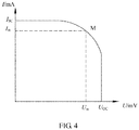
FIG. 4 is a V-I curve chart in working of photovoltaic cell strings. - The following clearly and completely describes the technical solutions in the embodiments of the present invention with reference to the accompanying drawings in the embodiments of the present invention. Apparently, the described embodiments are some but not all of the embodiments of the present invention. All other embodiments obtained by a person of ordinary skill in the art based on the embodiments of the present invention without creative efforts shall fall within the protection scope of the present invention.
- Referring to
FIG. 1, FIG. 1 is a schematic structural diagram of a photovoltaic system according to an embodiment of the present invention. As shown inFIG. 1 , the photovoltaic system includes multiple photovoltaic cell strings, a converter, a controller, and a bus, where the multiple photovoltaic cell strings include at least one string group in which two or three parallel-connected photovoltaic cell strings are connected to one current sensor, where the at least one string group, after being connected in parallel, is connected to the converter by using buses (1, 2), the converter is connected to the controller, and the controller is connected to a current sensor in each string group in the at least one string group, the current sensor is configured to detect a total current of each string group, and report whether a reverse current exists in each string group to the controller, the controller is configured to adjust, when receiving a report from the current sensor that a reverse current exists in a target string group in the at least one string group, a control signal output to the converter, and the converter is configured to decrease, according to the adjusted control signal, a system voltage between the buses (1, 2) to decrease the reverse current in the target string group. - Optionally, the multiple photovoltaic cell strings further include a string group in which one photovoltaic cell string is connected to one current sensor, where the string group in which one photovoltaic cell string is connected to one current sensor and the at least one string group in which two or three parallel-connected photovoltaic cell strings are connected to one current sensor, after being connected in parallel, are connected to the converter by using the buses (1, 2), and the current sensor in the string group in which one photovoltaic string is connected to one current sensor is connected to the controller.
- Optionally, as shown in
FIG. 2 , the converter includes a switching transistor, a first capacitor C1, an inductor L, and a first diode D1, where one end of the inductor L is connected to an input end of the converter, the other end of the inductor L is connected to both a collector of the switching transistor and a positive electrode of the first diode D1, a negative electrode of the first diode D1 is connected to one end of the first capacitor C1, and the other end of the first capacitor C1 is connected to both an emitter of the switching transistor and an output end of the converter. - Further, optionally, the converter further includes a second capacitor C2, where one end of the second capacitor C2 is connected to one end of the inductor L, the other end of the second capacitor C2 is connected to the emitter of the switching transistor, and the second capacitor C2 is configured to perform filtering processing on an input voltage.
- Optionally, as shown in
FIG. 3 , the controller includes aprocessor 302 and adriver 303. - The
processor 302 is configured to determine whether the reverse current in the target string group is higher than the preset threshold. - The
driver 303 is connected to the processor, and configured to adjust, when the processor determines that the reverse current in the target string group is higher than the preset threshold, the control signal output to the converter. - Further, optionally, the controller further includes an analog to
digital converter 301, where the analog todigital converter 301 is connected to theprocessor 302, and configured to convert an analog signal of the reverse current reported by the current sensor into a digital signal of the reverse current, and output the digital signal of the reverse current to the processor. - In this embodiment of the present invention, when the string group in which the reverse current exists includes one photovoltaic cell string, the controller adjusts the control signal output to the converter, and the converter decreases, according to the adjusted control signal, the system voltage between the buses (1, 2), to decrease the reverse current of the string group to lower than a short circuit current of a photovoltaic cell. When the string group in which the reverse current exists includes two or more photovoltaic cell strings, the controller adjusts the control signal output to the converter, and the converter decreases, according to the adjusted control signal, the system voltage between the buses (1, 2), to decrease the reverse current of the string group to 0.
- For example, as shown in
FIG. 1 , the photovoltaic system includes n string groups, and the n string groups include m photovoltaic cell strings, where a first string group includes one photovoltaic cell string, a second string group includes three photovoltaic cell strings, and an nth string group includes two photovoltaic cell strings. When a photovoltaic cell string 1 in the first string group is short-circuited, output currents of anotherphotovoltaic cell string 2 to a photovoltaic cell string m are all a maximum current value Isc , causing thephotovoltaic cell string 2 to the photovoltaic cell string m to feed a reverse current (m-1) Isc to the photovoltaic cell string 1, and a current sensor T1 detects that the reverse current exists in the first string group and that a current value of the reverse current is (m-1) Isc. Alternatively, when a photovoltaic cell string 1 in the second string group is short-circuited, output currents of aphotovoltaic cell string 2 to a photovoltaic cell string m are all a maximum current value Isc , causing thephotovoltaic cell string 2 to the photovoltaic cell string m to feed a reverse current (m-1) Isc to the photovoltaic cell string 1, and in this case, a current sensor T2 detects that the reverse current exists in the second string group and that a current value of the reverse current is (m-3) Isc. Alternatively, when a photovoltaic cell string 1 in the nth string group is short-circuited, output currents of aphotovoltaic cell string 2 to a photovoltaic cell string m are all a maximum current value Isc , causing thephotovoltaic cell string 2 to the photovoltaic cell string m to feed a reverse current (m-1) Isc to the photovoltaic cell string 1, and in this case, a current sensor Tn detects that the reverse current exists in the second string group and that a current value of the reverse current is (m-2) Isc. - In this case, the current sensor reports the reverse current to the controller. When the controller determines that the reverse current is higher than a preset threshold, the controller increases an output time of a high electrical level in each switching cycle to increase a duty cycle D of a control signal, and outputs, to the converter, the control signal whose duty cycle is increased. As shown in
FIG. 2 , the converter is a switching direct current boost circuit. The switching direct current boost circuit controls turn-on of the switching transistor by controlling the duty cycle of the input control signal, so as to control an output voltage. In the switching direct current boost circuit, a relationship between an output voltage vout and an input voltage vin is
FIG. 4 , when the input voltage vin provided by the cell group string circuit decreases, an output current of the cell group string circuit increases, and in this case, output currents of thephotovoltaic cell string 2 to the photovoltaic cell string m are all the maximum current value Isc , and a forward current of the photovoltaic cell string 1 increases, causing the reverse current of the photovoltaic cell string 1 to decrease, until the reverse current of the photovoltaic cell string 1 is lower than the short circuit current of the photovoltaic cell or is 0, thereby protecting the photovoltaic cell string. - In this embodiment of the present invention, a photovoltaic system includes multiple photovoltaic cell strings, a converter, a controller, and a bus, where the multiple photovoltaic cell strings include at least one string group in which two or three parallel-connected photovoltaic cell strings are connected to one current sensor, where the at least one string group, after being connected in parallel, is connected to the converter by using the bus, the converter is connected to the controller, and the controller is connected to a current sensor in each string group in the at least one string group, the current sensor is configured to detect a total current of each string group, and report whether a reverse current exists in each string group to the controller, the controller is configured to adjust, when receiving a report from the current sensor that a reverse current exists in a target string group in the at least one string group, a control signal output to the converter, and the converter is configured to decrease, according to an adjusted control signal, a system voltage between the buses to decrease the reverse current in the target string group. Therefore, not only photovoltaic cell protection can be provided, but also a device cost is decreased.
- It should be noted that, for brief description, the foregoing method embodiments are represented as a series of actions. However, a person skilled in the art should appreciate that the present invention is not limited to the described order of the actions, because according to the present invention, some steps may be performed in other orders or simultaneously. In addition, a person skilled in the art should also understand that all the embodiments described in this specification belong to exemplary embodiments, and the involved actions and modules are not necessarily mandatory to the present invention.
- In the foregoing embodiments, the description of each embodiment has respective focuses. For a part that is not described in detail in an embodiment, reference may be made to related descriptions in other embodiments.
- A person of ordinary skill in the art may understand that all or a part of the steps of the methods in the embodiments may be implemented by a program instructing relevant hardware. The program may be stored in a computer-readable storage medium. The storage medium may include a flash memory, a read-only memory (Read-Only Memory in English, ROM for short), a random access memory (Random Access Memory in English, RAM for short), a magnetic disk, and an optical disc.
- A content downloading method, a related device, and a system provided by the embodiments of the present invention are described in detail above. Although the principles and implementation manners of the present invention are described by using specific examples, the description of the embodiments is only intended to help understand the method and core idea of the present invention. In addition, with respect to the specific implementation manners and application scopes, modifications and variations may be made by a person of ordinary skill in the art according to the idea of the present invention. Therefore, content of the specification shall not be construed as a limitation on the present invention.
Claims (6)
- A photovoltaic system, wherein the photovoltaic system comprises multiple photovoltaic cell strings, a converter, a controller, and a bus, wherein the multiple photovoltaic cell strings comprise at least one string group in which two or three parallel-connected photovoltaic cell strings are connected to one current sensor, the at least one string group, after being connected in parallel, is connected to the converter by using the bus, the converter is connected to the controller, and the controller is connected to a current sensor in each string group in the at least one string group, the current sensor is configured to detect a total current of each string group, and report whether a reverse current exists in each string group to the controller, the controller is configured to adjust, when receiving a report from the current sensor that a reverse current exists in a target string group in the at least one string group, a control signal output to the converter, and the converter is configured to decrease, according to the adjusted control signal, a system voltage between the buses to decrease the reverse current in the target string group.
- The photovoltaic system according to claim 1, wherein the multiple photovoltaic cell strings further comprise a string group in which one photovoltaic cell string is connected to one current sensor, wherein the string group in which one photovoltaic cell string is connected to one current sensor and the at least one string group in which two or three parallel-connected photovoltaic cell strings are connected to one current sensor, after being connected in parallel, are connected to the converter by using the bus, and the current sensor in the string group in which one photovoltaic string is connected to one current sensor is connected to the controller.
- The photovoltaic system according to claim 1 or 2, wherein the converter comprises a switching transistor, a first capacitor, an inductor, and a first diode, wherein:one end of the inductor is connected to an input end of the converter, the other end of the inductor is connected to both a collector of the switching transistor and a positive electrode of the first diode, a negative electrode of the first diode is connected to one end of the first capacitor, and the other end of the first capacitor is connected to both an emitter of the switching transistor and an output end of the converter.
- The photovoltaic system according to claim 1 or 2, wherein the controller comprises a processor and a driver, wherein:the processor is configured to determine whether the reverse current in the target string group is higher than the preset threshold; andthe driver is connected to the processor, and configured to adjust, when the processor determines that the reverse current in the target string group is higher than the preset threshold, the control signal output to the converter.
- The photovoltaic system according to claim 4, wherein the controller further comprises an analog to digital converter, wherein the analog to digital converter is connected to the processor, and configured to convert an analog signal of the reverse current reported by the current sensor into a digital signal of the reverse current, and output the digital signal of the reverse current to the processor.
- The photovoltaic system according to claim 3, wherein the converter further comprises a second capacitor, wherein one end of the second capacitor is connected to one end of the inductor, the other end of the second capacitor is connected to the emitter of the switching transistor, and the second capacitor is configured to perform filtering processing on the input voltage.
Applications Claiming Priority (2)
| Application Number | Priority Date | Filing Date | Title |
|---|---|---|---|
| CN201510003630.9A CN105827179B (en) | 2015-01-04 | 2015-01-04 | A kind of photovoltaic system |
| PCT/CN2015/086244 WO2016107176A1 (en) | 2015-01-04 | 2015-08-06 | Photovoltaic system |
Publications (2)
| Publication Number | Publication Date |
|---|---|
| EP3174196A1 true EP3174196A1 (en) | 2017-05-31 |
| EP3174196A4 EP3174196A4 (en) | 2017-07-26 |
Family
ID=56284121
Family Applications (1)
| Application Number | Title | Priority Date | Filing Date |
|---|---|---|---|
| EP15874865.7A Withdrawn EP3174196A4 (en) | 2015-01-04 | 2015-08-06 | Photovoltaic system |
Country Status (5)
| Country | Link |
|---|---|
| US (1) | US20170222440A1 (en) |
| EP (1) | EP3174196A4 (en) |
| JP (1) | JP2017530680A (en) |
| CN (1) | CN105827179B (en) |
| WO (1) | WO2016107176A1 (en) |
Families Citing this family (5)
| Publication number | Priority date | Publication date | Assignee | Title |
|---|---|---|---|---|
| US10218182B2 (en) * | 2016-09-22 | 2019-02-26 | Sunpower Corporation | Photovoltaic systems with voltage limiting devices |
| US11139670B2 (en) * | 2017-08-14 | 2021-10-05 | Richtek Technology Corporation | Charger circuit with temperature compensation function and controller circuit thereof |
| CN109460107B (en) * | 2017-09-06 | 2021-04-13 | 阳光电源股份有限公司 | A method for adjusting output characteristics of photovoltaic modules and a DC/DC converter |
| WO2021207880A1 (en) * | 2020-04-13 | 2021-10-21 | 华为技术有限公司 | Short circuit protection apparatus, short circuit protection method, and photovoltaic power generation system |
| CN111682846B (en) * | 2020-06-17 | 2021-07-20 | 阳光电源股份有限公司 | A kind of fault diagnosis method and diagnosis equipment |
Family Cites Families (17)
| Publication number | Priority date | Publication date | Assignee | Title |
|---|---|---|---|---|
| JP2002252986A (en) * | 2001-02-26 | 2002-09-06 | Canon Inc | Inverter, power supply system and method of reducing leakage current in power supply system |
| EP1946418A2 (en) * | 2005-10-24 | 2008-07-23 | Conergy AG | Switch-fuse with control management for solar cells |
| US8013472B2 (en) * | 2006-12-06 | 2011-09-06 | Solaredge, Ltd. | Method for distributed power harvesting using DC power sources |
| EP2104200B1 (en) * | 2008-03-22 | 2019-02-27 | SMA Solar Technology AG | Method for controlling a multi-string inverter for photovoltaic systems |
| EP2282388A1 (en) * | 2009-08-06 | 2011-02-09 | SMA Solar Technology AG | Device for feeding in electrical energy of a number of strings of photovoltaic modules in an electricity network |
| ATE555531T1 (en) * | 2009-08-06 | 2012-05-15 | Sma Solar Technology Ag | RETURN CURRENT SENSOR FOR PARALLEL CONNECTED SOLAR MODULES |
| US7989983B2 (en) * | 2009-11-24 | 2011-08-02 | American Superconductor Corporation | Power conversion systems |
| DE102010009079B4 (en) * | 2010-02-24 | 2018-02-22 | Adensis Gmbh | Method and device for finding low-power PV modules in a PV system by means of disconnectors |
| DE102010012294B4 (en) * | 2010-03-23 | 2012-04-26 | Adensis Gmbh | Photovoltaic system with potential reduction |
| US20120187766A1 (en) * | 2010-09-23 | 2012-07-26 | Hybridine Power Electronics Inc. | Device and Method For Improving The Performance Of An Inverter In A Photovoltaic System |
| JP2012253848A (en) * | 2011-05-31 | 2012-12-20 | Toshiba Corp | Photovoltaic power generation system |
| EP2799892B1 (en) * | 2011-12-26 | 2018-07-11 | Toshiba Mitsubishi-Electric Industrial Systems Corporation | Breakdown detection device and detection method thereof |
| CN102769398A (en) * | 2012-06-11 | 2012-11-07 | 合肥工业大学 | Modular multilevel converter for photovoltaic grid-connected systems |
| DE102012112184A1 (en) * | 2012-12-12 | 2014-06-12 | Sma Solar Technology Ag | Method and device for protecting multiple strings of a photovoltaic generator from backflow |
| EP2775531A1 (en) * | 2013-03-07 | 2014-09-10 | ABB Oy | Method and arrangement for operating photovoltaic system and photovoltaic system |
| CN103780071B (en) * | 2014-01-21 | 2016-08-17 | 广东易事特电源股份有限公司 | A kind of over-pressure safety device and photovoltaic generating system |
| CN104143835B (en) * | 2014-07-30 | 2016-08-17 | 深圳科士达科技股份有限公司 | A kind of photovoltaic generating system |
-
2015
- 2015-01-04 CN CN201510003630.9A patent/CN105827179B/en active Active
- 2015-08-06 JP JP2017516712A patent/JP2017530680A/en active Pending
- 2015-08-06 WO PCT/CN2015/086244 patent/WO2016107176A1/en not_active Ceased
- 2015-08-06 EP EP15874865.7A patent/EP3174196A4/en not_active Withdrawn
-
2017
- 2017-04-21 US US15/493,370 patent/US20170222440A1/en not_active Abandoned
Also Published As
| Publication number | Publication date |
|---|---|
| US20170222440A1 (en) | 2017-08-03 |
| JP2017530680A (en) | 2017-10-12 |
| WO2016107176A1 (en) | 2016-07-07 |
| EP3174196A4 (en) | 2017-07-26 |
| CN105827179A (en) | 2016-08-03 |
| CN105827179B (en) | 2018-09-07 |
Similar Documents
| Publication | Publication Date | Title |
|---|---|---|
| AU2021202396B2 (en) | Method for starting photovoltaic rapid shutdown system, application apparatus and system | |
| US20170222440A1 (en) | Photovoltaic System | |
| EP3163702B1 (en) | Over-current protection system and method for inverter circuit | |
| CN104333213B (en) | Guard method, equipment and system during a kind of PV arrays output overvoltage | |
| US8929038B2 (en) | Method and device for safely switching a photovoltaic system after differentiating the arc type | |
| US10411586B2 (en) | Circuit and method for overcurrent control and power supply system including the same | |
| SE1951300A1 (en) | Battery assembly with controllable voltage and method related thereto | |
| US11683008B2 (en) | Photovoltaic inverter, photovoltaic system, and method for controlling discharging | |
| EP3979492B1 (en) | Electric energy backward-flow control method, converter, and photovoltaic power generation system | |
| EP3142238B1 (en) | Inverter and control device and method thereof, and inverter system | |
| US9601986B2 (en) | Method and arrangement for the surge protection of inverters for photovoltaic systems | |
| EP4231480A1 (en) | Photovoltaic power generation system control method and apparatus, power optimizer, and storage medium | |
| US10044291B2 (en) | Method and device for modulating a five-level inverter, and photovoltaic system | |
| AU2019431775B9 (en) | Power conversion apparatus, and method controlling output impedance of power conversion apparatus | |
| CN110249497A (en) | Bus voltage regulation method and related equipment | |
| EP3855595A1 (en) | Photovoltaic system | |
| CN114696604B (en) | A symmetrical three-level BOOST converter and its short-circuit protection method | |
| US20170155255A1 (en) | Charging/discharging control circuit and battery apparatus | |
| US10044274B2 (en) | Protection circuit for power supply | |
| JP6242128B2 (en) | Power converter | |
| US10396649B2 (en) | Switching device and switching apparatus including the same | |
| CN107769318A (en) | Charging circuit, device, intelligent terminal and charging method | |
| US20250192571A1 (en) | Method and device for controlling inverter, inverter and photovoltaic system | |
| WO2013009123A2 (en) | Switching mode power supply apparatus comprising overvoltage protection circuit |
Legal Events
| Date | Code | Title | Description |
|---|---|---|---|
| PUAI | Public reference made under article 153(3) epc to a published international application that has entered the european phase |
Free format text: ORIGINAL CODE: 0009012 |
|
| 17P | Request for examination filed |
Effective date: 20170223 |
|
| AK | Designated contracting states |
Kind code of ref document: A1 Designated state(s): AL AT BE BG CH CY CZ DE DK EE ES FI FR GB GR HR HU IE IS IT LI LT LU LV MC MK MT NL NO PL PT RO RS SE SI SK SM TR |
|
| AX | Request for extension of the european patent |
Extension state: BA ME |
|
| A4 | Supplementary search report drawn up and despatched |
Effective date: 20170622 |
|
| RIC1 | Information provided on ipc code assigned before grant |
Ipc: H02S 50/00 20140101ALI20170616BHEP Ipc: H02S 10/00 20140101AFI20170616BHEP |
|
| 17Q | First examination report despatched |
Effective date: 20180212 |
|
| DAV | Request for validation of the european patent (deleted) | ||
| DAX | Request for extension of the european patent (deleted) | ||
| STAA | Information on the status of an ep patent application or granted ep patent |
Free format text: STATUS: THE APPLICATION IS DEEMED TO BE WITHDRAWN |
|
| 18D | Application deemed to be withdrawn |
Effective date: 20181103 |