EP3174127A2 - Secondary battery and fabricating method thereof - Google Patents
Secondary battery and fabricating method thereof Download PDFInfo
- Publication number
- EP3174127A2 EP3174127A2 EP16179649.5A EP16179649A EP3174127A2 EP 3174127 A2 EP3174127 A2 EP 3174127A2 EP 16179649 A EP16179649 A EP 16179649A EP 3174127 A2 EP3174127 A2 EP 3174127A2
- Authority
- EP
- European Patent Office
- Prior art keywords
- metal board
- electrode
- thickness
- electrode plate
- secondary battery
- Prior art date
- Legal status (The legal status is an assumption and is not a legal conclusion. Google has not performed a legal analysis and makes no representation as to the accuracy of the status listed.)
- Granted
Links
Images



Classifications
-
- H—ELECTRICITY
- H01—ELECTRIC ELEMENTS
- H01M—PROCESSES OR MEANS, e.g. BATTERIES, FOR THE DIRECT CONVERSION OF CHEMICAL ENERGY INTO ELECTRICAL ENERGY
- H01M10/00—Secondary cells; Manufacture thereof
- H01M10/05—Accumulators with non-aqueous electrolyte
- H01M10/058—Construction or manufacture
- H01M10/0587—Construction or manufacture of accumulators having only wound construction elements, i.e. wound positive electrodes, wound negative electrodes and wound separators
-
- H—ELECTRICITY
- H01—ELECTRIC ELEMENTS
- H01M—PROCESSES OR MEANS, e.g. BATTERIES, FOR THE DIRECT CONVERSION OF CHEMICAL ENERGY INTO ELECTRICAL ENERGY
- H01M50/00—Constructional details or processes of manufacture of the non-active parts of electrochemical cells other than fuel cells, e.g. hybrid cells
- H01M50/10—Primary casings; Jackets or wrappings
- H01M50/147—Lids or covers
- H01M50/148—Lids or covers characterised by their shape
- H01M50/15—Lids or covers characterised by their shape for prismatic or rectangular cells
-
- H—ELECTRICITY
- H01—ELECTRIC ELEMENTS
- H01M—PROCESSES OR MEANS, e.g. BATTERIES, FOR THE DIRECT CONVERSION OF CHEMICAL ENERGY INTO ELECTRICAL ENERGY
- H01M50/00—Constructional details or processes of manufacture of the non-active parts of electrochemical cells other than fuel cells, e.g. hybrid cells
- H01M50/10—Primary casings; Jackets or wrappings
- H01M50/102—Primary casings; Jackets or wrappings characterised by their shape or physical structure
- H01M50/103—Primary casings; Jackets or wrappings characterised by their shape or physical structure prismatic or rectangular
-
- H—ELECTRICITY
- H01—ELECTRIC ELEMENTS
- H01M—PROCESSES OR MEANS, e.g. BATTERIES, FOR THE DIRECT CONVERSION OF CHEMICAL ENERGY INTO ELECTRICAL ENERGY
- H01M10/00—Secondary cells; Manufacture thereof
- H01M10/04—Construction or manufacture in general
-
- H—ELECTRICITY
- H01—ELECTRIC ELEMENTS
- H01M—PROCESSES OR MEANS, e.g. BATTERIES, FOR THE DIRECT CONVERSION OF CHEMICAL ENERGY INTO ELECTRICAL ENERGY
- H01M10/00—Secondary cells; Manufacture thereof
- H01M10/60—Heating or cooling; Temperature control
- H01M10/61—Types of temperature control
- H01M10/613—Cooling or keeping cold
-
- H—ELECTRICITY
- H01—ELECTRIC ELEMENTS
- H01M—PROCESSES OR MEANS, e.g. BATTERIES, FOR THE DIRECT CONVERSION OF CHEMICAL ENERGY INTO ELECTRICAL ENERGY
- H01M10/00—Secondary cells; Manufacture thereof
- H01M10/60—Heating or cooling; Temperature control
- H01M10/64—Heating or cooling; Temperature control characterised by the shape of the cells
- H01M10/647—Prismatic or flat cells, e.g. pouch cells
-
- H—ELECTRICITY
- H01—ELECTRIC ELEMENTS
- H01M—PROCESSES OR MEANS, e.g. BATTERIES, FOR THE DIRECT CONVERSION OF CHEMICAL ENERGY INTO ELECTRICAL ENERGY
- H01M10/00—Secondary cells; Manufacture thereof
- H01M10/60—Heating or cooling; Temperature control
- H01M10/65—Means for temperature control structurally associated with the cells
- H01M10/655—Solid structures for heat exchange or heat conduction
- H01M10/6551—Surfaces specially adapted for heat dissipation or radiation, e.g. fins or coatings
-
- H—ELECTRICITY
- H01—ELECTRIC ELEMENTS
- H01M—PROCESSES OR MEANS, e.g. BATTERIES, FOR THE DIRECT CONVERSION OF CHEMICAL ENERGY INTO ELECTRICAL ENERGY
- H01M50/00—Constructional details or processes of manufacture of the non-active parts of electrochemical cells other than fuel cells, e.g. hybrid cells
- H01M50/10—Primary casings; Jackets or wrappings
- H01M50/116—Primary casings; Jackets or wrappings characterised by the material
- H01M50/117—Inorganic material
- H01M50/119—Metals
-
- H—ELECTRICITY
- H01—ELECTRIC ELEMENTS
- H01M—PROCESSES OR MEANS, e.g. BATTERIES, FOR THE DIRECT CONVERSION OF CHEMICAL ENERGY INTO ELECTRICAL ENERGY
- H01M50/00—Constructional details or processes of manufacture of the non-active parts of electrochemical cells other than fuel cells, e.g. hybrid cells
- H01M50/10—Primary casings; Jackets or wrappings
- H01M50/131—Primary casings; Jackets or wrappings characterised by physical properties, e.g. gas permeability, size or heat resistance
- H01M50/133—Thickness
-
- H—ELECTRICITY
- H01—ELECTRIC ELEMENTS
- H01M—PROCESSES OR MEANS, e.g. BATTERIES, FOR THE DIRECT CONVERSION OF CHEMICAL ENERGY INTO ELECTRICAL ENERGY
- H01M50/00—Constructional details or processes of manufacture of the non-active parts of electrochemical cells other than fuel cells, e.g. hybrid cells
- H01M50/20—Mountings; Secondary casings or frames; Racks, modules or packs; Suspension devices; Shock absorbers; Transport or carrying devices; Holders
- H01M50/233—Mountings; Secondary casings or frames; Racks, modules or packs; Suspension devices; Shock absorbers; Transport or carrying devices; Holders characterised by physical properties of casings or racks, e.g. dimensions
- H01M50/24—Mountings; Secondary casings or frames; Racks, modules or packs; Suspension devices; Shock absorbers; Transport or carrying devices; Holders characterised by physical properties of casings or racks, e.g. dimensions adapted for protecting batteries from their environment, e.g. from corrosion
-
- H—ELECTRICITY
- H01—ELECTRIC ELEMENTS
- H01M—PROCESSES OR MEANS, e.g. BATTERIES, FOR THE DIRECT CONVERSION OF CHEMICAL ENERGY INTO ELECTRICAL ENERGY
- H01M50/00—Constructional details or processes of manufacture of the non-active parts of electrochemical cells other than fuel cells, e.g. hybrid cells
- H01M50/50—Current conducting connections for cells or batteries
- H01M50/531—Electrode connections inside a battery casing
- H01M50/533—Electrode connections inside a battery casing characterised by the shape of the leads or tabs
-
- H—ELECTRICITY
- H01—ELECTRIC ELEMENTS
- H01M—PROCESSES OR MEANS, e.g. BATTERIES, FOR THE DIRECT CONVERSION OF CHEMICAL ENERGY INTO ELECTRICAL ENERGY
- H01M50/00—Constructional details or processes of manufacture of the non-active parts of electrochemical cells other than fuel cells, e.g. hybrid cells
- H01M50/10—Primary casings; Jackets or wrappings
- H01M50/131—Primary casings; Jackets or wrappings characterised by physical properties, e.g. gas permeability, size or heat resistance
-
- Y—GENERAL TAGGING OF NEW TECHNOLOGICAL DEVELOPMENTS; GENERAL TAGGING OF CROSS-SECTIONAL TECHNOLOGIES SPANNING OVER SEVERAL SECTIONS OF THE IPC; TECHNICAL SUBJECTS COVERED BY FORMER USPC CROSS-REFERENCE ART COLLECTIONS [XRACs] AND DIGESTS
- Y02—TECHNOLOGIES OR APPLICATIONS FOR MITIGATION OR ADAPTATION AGAINST CLIMATE CHANGE
- Y02E—REDUCTION OF GREENHOUSE GAS [GHG] EMISSIONS, RELATED TO ENERGY GENERATION, TRANSMISSION OR DISTRIBUTION
- Y02E60/00—Enabling technologies; Technologies with a potential or indirect contribution to GHG emissions mitigation
- Y02E60/10—Energy storage using batteries
-
- Y—GENERAL TAGGING OF NEW TECHNOLOGICAL DEVELOPMENTS; GENERAL TAGGING OF CROSS-SECTIONAL TECHNOLOGIES SPANNING OVER SEVERAL SECTIONS OF THE IPC; TECHNICAL SUBJECTS COVERED BY FORMER USPC CROSS-REFERENCE ART COLLECTIONS [XRACs] AND DIGESTS
- Y02—TECHNOLOGIES OR APPLICATIONS FOR MITIGATION OR ADAPTATION AGAINST CLIMATE CHANGE
- Y02P—CLIMATE CHANGE MITIGATION TECHNOLOGIES IN THE PRODUCTION OR PROCESSING OF GOODS
- Y02P70/00—Climate change mitigation technologies in the production process for final industrial or consumer products
- Y02P70/50—Manufacturing or production processes characterised by the final manufactured product
Definitions
- Embodiments of the present invention relate to a secondary battery and a fabricating method thereof.
- Secondary batteries are configured to be discharged and recharged, unlike primary batteries, which are not configured to be rechargeable.
- Secondary batteries may be of a low capacity type, which includes a single battery cell packaged in the form of a pack typically used for small portable electronic devices, such as cellular phones and camcorders, or a high capacity type, which includes several tens of battery packs connected to one another and is widely used as a power source for driving a motor, such as a motor of a hybrid vehicle, etc.
- the secondary battery is subjected to safety tests including electrical tests, such as short-circuiting, abnormal charging, over-charging, or forced discharging, and tests for stability (e.g., resistance to explosion or ignition of the secondary battery) in a physically unstable situation, such as vibration, falling, or shocks.
- electrical tests such as short-circuiting, abnormal charging, over-charging, or forced discharging
- stability e.g., resistance to explosion or ignition of the secondary battery
- a physically unstable situation such as vibration, falling, or shocks.
- Embodiments of the present invention provide a secondary battery and a fabricating method thereof, which can improve heat radiation efficiency while reducing deformation of a can during a drop or collision test.
- a secondary battery includes an electrode assembly including a first electrode plate, a second electrode plate. and a separator between the first electrode plate and the second electrode plate, a can accommodating the electrode assembly, and a cap assembly coupled to and sealing the can, wherein a top end and a bottom end of the can each have a thickness that is greater than a thickness of a middle portion of the can.
- the can may include metal boards having different thicknesses, and the metal boards may be welded together to form a unitary metal board.
- the unitary metal board may be folded, and end portions of the unitary metal board may be welded together.
- the secondary battery may further include a first electrode tab electrically connected to the first electrode plate and downwardly protruding from the electrode assembly, and the first electrode tab may be welded to a bottom surface of the can.
- a method of fabricating a secondary battery includes forming a can having a top end and a bottom end having respective thicknesses that are greater than a thickness of a middle portion of the can, inserting an electrode assembly into the can, the electrode assembly including a first electrode plate, a second electrode plate, and a separator between the first electrode plate and the second electrode plate, and coupling a cap assembly to the can.
- the forming of the can may include welding a first metal board having a first thickness, a second metal board having a second thickness and a third metal board having a third thickness to each other to form a unitary metal board.
- the forming of the can may further include folding the unitary metal board, and welding end portions of the unitary metal board that are adjacent to each other after folding.
- the first thickness of the first metal board may be the same as the second thickness of the second metal board, and the third thickness of the third metal board may be less than the first and second thicknesses.
- the third metal board may be arranged between the first metal board and the second metal board.
- the fabricating method may further include welding a first electrode tab to a bottom surface of the can, and the first electrode tab may be electrically connected to the first electrode plate and may protrude downwardly from the electrode assembly.
- respective thicknesses of a top end and a bottom end of a can are greater than a thickness of a middle portion of the can, thereby reducing or minimizing deformation of the can during a drop or collision test and improving heat radiation efficiency.
- metal boards having different thicknesses are welded to each other and are then folded to form the can. Accordingly, the method of fabricating the secondary battery according to one or more embodiments of the present invention may be facilitated. In addition, deformation of the can during a drop or collision test may be reduced or minimized by different strengths at different regions of the can.
- spatially relative terms such as “beneath,” “below,” “lower,” “under,” “bottom,” “above,” “upper,” “top,” and the like, may be used herein for ease of explanation to describe one element or feature's relationship to another element(s) or feature(s) as illustrated in the figures. It will be understood that the spatially relative terms are intended to encompass different orientations of the device in use or in operation, in addition to the orientation depicted in the figures. For example, if the device in the figures is turned over, elements described as “below” or “beneath” or “under” other elements or features would then be oriented “above” the other elements or features. Thus, the example terms “below” and “under” can encompass both an orientation of above and below. The device may be otherwise oriented (e.g., rotated 90 degrees or at other orientations) and the spatially relative descriptors used herein should be interpreted accordingly.
- the terms “substantially,” “about,” and similar terms are used as terms of approximation and not as terms of degree and are intended to account for the inherent variations in measured or calculated values that would be recognized by those of ordinary skill in the art. Further, the use of “may” when describing embodiments of the present invention refers to “one or more embodiments of the present invention.” In addition, the use of alternative language, such as “or,” when describing embodiments of the present invention, refers to “one or more embodiments of the present invention” for each corresponding item listed. As used herein, the terms “use,” “using,” and “used” may be considered synonymous with the terms “utilize,” “utilizing,” and “utilized,” respectively. Also, the term “exemplary” is intended to refer to an example or illustration.
- any numerical range disclosed and/or recited herein is intended to include all sub-ranges of the same numerical precision subsumed within the recited range.
- a range of "1.0 to 10.0" is intended to include all subranges between (and including) the recited minimum value of 1.0 and the recited maximum value of 10.0, that is, having a minimum value equal to or greater than 1.0 and a maximum value equal to or less than 10.0, such as, for example, 2.4 to 7.6.
- Any maximum numerical limitation recited herein is intended to include all lower numerical limitations subsumed therein, and any minimum numerical limitation recited in this specification is intended to include all higher numerical limitations subsumed therein.
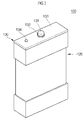
- FIG. 1 is a perspective view of a secondary battery according to one or more embodiments of the present invention
- FIG. 2 is an exploded perspective view of the secondary battery illustrated in FIG. 1
- FIG. 3 is a cross-sectional view taken along the line I-I' of FIG. 2
- FIG. 4 is a cross-sectional view of a can according to one or more embodiments of the present invention.
- a secondary battery 100 includes an electrode assembly 110, a can 120, and a cap assembly 130.
- the electrode assembly 110 includes a first electrode plate 111, a second electrode plate 112, and a separator 113 interposed between the first electrode plate 111 and the second electrode plate 112.
- the electrode assembly 110 may be formed by winding a stacked structure of the electrode plate 111, the separator 113, and the second electrode plate 112.
- the first electrode plate 111 may function as a positive electrode and the second electrode plate 112 may function as a negative electrode.
- the present invention is not limited thereto.
- the first electrode plate 111 may be formed by coating a first electrode active material, such as a transition metal oxide, on a first electrode collector made of a metal foil, such as aluminum (Al) or an aluminum foil.
- a first electrode tab 114 is attached to the first electrode plate 111.
- One end (e.g., a first end) of the first electrode tab 114 is connected (e.g., electrically connected) to the first electrode plate 111, and another end (e.g., a second end opposite to the first end) of the first electrode tab 114 protrudes downwardly from the electrode assembly 110.
- the first electrode tab 114 may be connected to (e.g., electrically connected to) the can 120.
- the second electrode plate 112 may be formed by coating a second electrode active material, such as graphite or carbon, on a second electrode collector made of a metal foil, such as a copper (Cu) foil or a nickel (Ni) foil.
- a second electrode tab 115 is attached to the second electrode plate 112.
- One end (e.g., a first end) of the second electrode tab 115 is connected (e.g., electrically connected) to the second electrode plate 112, and another end (e.g., a second end opposite to the first end) of the second electrode tab 115 protrudes upwardly from the electrode assembly 110.
- the separator 113 may be between (e.g., may be positioned between) the first electrode plate 111 and the second electrode plate 112 to prevent electrical short circuits therebetween and to allow movement of lithium ions.
- the separator 113 may include (e.g., may be made of) polyethylene, polypropylene, or a composite film including polypropylene and/or polyethylene.
- the electrode assembly 110 is accommodated in the can 120 together with an electrolyte.
- the electrolyte may include a mixture containing a lithium salt, such as lithium hexafluorophosphate (LiPF 6 ) or lithium tetrafluoroborate (LiBF 4 ) dissolved in an organic solvent, such as ethylene carbonate (EC), propylene carbonate (PC), diethyl carbonate (DEC), ethyl methyl carbonate (EMC), and/or dimethyl carbonate (DMC).
- a lithium salt such as lithium hexafluorophosphate (LiPF 6 ) or lithium tetrafluoroborate (LiBF 4 ) dissolved in an organic solvent, such as ethylene carbonate (EC), propylene carbonate (PC), diethyl carbonate (DEC), ethyl methyl carbonate (EMC), and/or dimethyl carbonate (DMC).
- EC ethylene carbonate
- PC propylene carbonate
- DEC dieth
- the can 120 has a substantially hexahedral shape having an opening through which the electrode assembly 110 is inserted and positioned.
- the can 120 has a bottom surface 121, a pair of long side surfaces 122 upwardly protruding from the bottom surface 121 and having relatively large areas, and a pair of short side surfaces 123 upwardly protruding from the bottom surface 121 and having relatively small areas.
- the can 120 is made of a conductive metal, such as aluminum, an aluminum alloy, or nickel plated steel.
- the can 120 may function as a positive electrode.
- the present invention is not limited thereto.
- a force applied to the can 120 may be concentrated at top and bottom ends of the can 120 rather than at a central (or middle) portion the can 120. Therefore, according to one or more embodiments of the present invention, the top and bottom ends of the can 120 respectively have greater thicknesses than the middle portion of the can 120, thereby providing a structure capable of reducing (or minimizing) deformation of the can 120 during the drop or collision test of the secondary battery 100.
- the structure of the can 120 is described below in more detail.
- the cap assembly 130 is located (or positioned) on the electrode assembly 110 and is coupled to the can 120 at the opening to seal the can 120.
- the cap assembly 130 includes an electrode terminal 131, a gasket 132, a cap plate 133, an insulation plate 136, a terminal plate 137, and an insulation case 138.
- the gasket 132 is located (or inserted) between the electrode terminal 131 and the cap plate 133, and the electrode terminal 131 and the terminal plate 137 are electrically connected to each other.
- the insulation plate 136 insulates the cap plate 133 and the terminal plate 137 from each other.
- An electrolyte injection opening (e.g., an electrolyte injection hole) 134 is defined in one side of the cap plate 133.
- a plug is installed to seal the electrolyte injection opening 134.
- a safety vent 135 is formed at an opposite side of the cap plate 133.
- the safety vent 135 is formed to be thinner than the cap plate 133. In other words, a thickness of the safety vent 135 is less than a thickness of the cap plate 133. If an internal pressure of the can 120 exceeds an operating pressure of the safety vent 135, the safety vent 135 opens to release gases.
- the insulation case 138 is located at the opening of the can 120 to seal the can 120.
- the insulation case 138 includes a polymer resin having an insulating property and may be made of polypropylene (PP).
- An opening (e.g., a hole) 138a is defined in the insulation case 138 to allow the second electrode tab 115 to pass therethrough.
- an electrolyte opening (e.g., an electrolyte passing hole) 138b is defined in the insulation case 138 so as correspond to the electrolyte injection opening 134.
- the structure of the can 120 is described in more detail below with reference to FIGS. 2 and 3 .
- the can 120 may be divided into three regions along a height direction thereof. According to one or more embodiments of the present invention, the three regions are defined as a first region A1, a second region A2, and a third region A3.
- the first region A1 is defined as an upper portion of the can 120, also referred to herein as a top end
- the second region A2 is defined as a lower portion of the can 120, also referred to herein as a bottom end
- the third region A3 is defined as a central (or middle) portion of the can 120 between the first region A1 and the second region A2.
- a first thickness T1 of the top end and a second thickness T2 of the bottom end are larger than a third thickness T3 of the middle portion.
- deformation of the top and bottom ends A1 and A2 of the can 120 is more severe than deformation of the middle portion A3.
- the can 120 is formed such that the first and second thicknesses T1 and T2 of the top and bottom ends A1 and A2 are greater than the thickness T3 of the middle portion A3, thereby reducing or minimizing deformation of the can 120 during the drop or collision test of the secondary battery 100.
- the first and second thicknesses T1 and T2 of the top and bottom ends A1 and A2 may be in a range of about 0.6 mm to about 0.8 mm.
- the can 120 is prone to deformation during the drop or collision test of the secondary battery 100.
- the can 120 may be formed by folding a metal board (e.g., a metal sheet).
- the metal board may not be readily folded, making it difficult to form the can 120.
- the third thickness T3 of the middle portion A3 may be in a range of about 0.3 mm to about 0.6 mm.
- the first thickness T1 of the top end A1 and the second thickness T2 of the bottom end A2 may be different from each other (i.e., T1 ⁇ T2).
- the can 120 may be formed by welding metal boards having different thicknesses. The method of forming the can 120 according to one or more exemplary embodiments is described below in more detail.
- the bottom end A2 includes a bottom surface 121 of the can 120.
- the first electrode tab 114 of the electrode assembly 110 may be welded (e.g., directly welded) to the bottom surface 121. Therefore, the fourth thickness T4 of the bottom surface 121 may be relatively large, thereby increasing heat radiation efficiency.
- top end A1 and the bottom end A2 may protrude outwardly from the can 120.
- the top end A1 and the bottom end A2 may protrude into the can 120.
- the can 120 is formed such that the first and second thicknesses T1 and T2 of the top and bottom ends A1 and A2 are greater than the third thickness T3 of the middle portion A3, thereby improving the heat radiation efficiency while reducing or minimizing deformation of the can 120 during the drop or collision test of the secondary battery 100.
- FIGS. 5A-5E are schematic views illustrating a method of fabricating a secondary battery according to one or more embodiments of the present invention.
- the method of fabricating a secondary battery according to one or more embodiments of the present invention includes forming a can, inserting an electrode assembly into the can, and coupling a cap assembly to a top portion of the can.
- a first metal board 120a having a first thickness T1, a second metal board 120b having a second thickness T2, and a third metal board 120c having a third thickness T3 are prepared.
- first metal board 120a, the second metal board 120b, and the third metal board 120c are cut according to (e.g., to conform to) the shape of the can 120.
- first metal board 120a, the second metal board 120b, and the third metal board 120c may be welded to one another and then cut according to the shape of the can 120.
- the first metal board 120a, the second metal board 120b, and the third metal board 120c may be made of a conductive metal, such as aluminum, an aluminum alloy, or nickel plated steel.
- the first metal board 120a, the second metal board 120b, and the third metal board 120c are connected to one another by welding to form a single (or unitary) metal board.
- the welding of the metal boards having different thicknesses may be performed using tailor welded blank (TWB) technology.
- TWB tailor welded blank
- the welding is performed in a state in which the third metal board 120c is positioned between the first metal board 120a and the second metal board 120b.
- the metal boards are welded into one single unit (or a unitary metal board), are folded along the dotted lines shown in FIG.
- the can 120 has a bottom surface 121, a pair of long side surfaces 122 upwardly protruding from the bottom surface 121 and having relatively large areas, and a pair of short side surfaces 123 upwardly protruding from the bottom surface 121 and having relatively small areas.
- the bottom surface 121 of the can 120 is illustrated as being integrally formed with the second metal board 120b, in some embodiments, the bottom surface 121 may be a separate component from the second metal board 120b and may have a thickness that is different from that of the second metal board 120b. As such, the bottom surface 121 may be connected to the can 120 by, for example, a separate welding process.
- the electrode assembly 110 is inserted into the can 120. Then, as illustrated in FIG. 5E , during the coupling of the cap assembly 130, the cap assembly 130 is coupled to a top portion of the can 120 having the electrode assembly 110 inserted therein.
- the electrode assembly 110 and the cap assembly 130 are the same or substantially the same as those described above, and detailed descriptions thereof may be omitted.
- the method of fabricating the secondary battery 100 according to one or more embodiments of the present invention may facilitate formation of the can 120 and can reduce or minimize deformation of the can 120 during a drop or collision test by forming the can 120 have different strengths at different regions.
Landscapes
- Chemical & Material Sciences (AREA)
- Chemical Kinetics & Catalysis (AREA)
- Electrochemistry (AREA)
- General Chemical & Material Sciences (AREA)
- Engineering & Computer Science (AREA)
- Manufacturing & Machinery (AREA)
- Inorganic Chemistry (AREA)
- Sealing Battery Cases Or Jackets (AREA)
- Connection Of Batteries Or Terminals (AREA)
- Secondary Cells (AREA)
Abstract
Description
- This application claims priority to and the benefit of
Korean Patent Application No. 10-2015-0164898, filed on November 24, 2015 - Embodiments of the present invention relate to a secondary battery and a fabricating method thereof.
- Secondary batteries are configured to be discharged and recharged, unlike primary batteries, which are not configured to be rechargeable. Secondary batteries may be of a low capacity type, which includes a single battery cell packaged in the form of a pack typically used for small portable electronic devices, such as cellular phones and camcorders, or a high capacity type, which includes several tens of battery packs connected to one another and is widely used as a power source for driving a motor, such as a motor of a hybrid vehicle, etc.
- To avoid or reduce a risk of explosion or fire, the secondary battery is subjected to safety tests including electrical tests, such as short-circuiting, abnormal charging, over-charging, or forced discharging, and tests for stability (e.g., resistance to explosion or ignition of the secondary battery) in a physically unstable situation, such as vibration, falling, or shocks. For example, during a drop or collision test from among various safety tests of secondary batteries, impacts to top and bottom ends of a can are more severe than impacts to a central portion of the can because the top and bottom ends of the can are more prone to deformation. Therefore, there exists a need for a structure for reinforcing the strength of the top and bottom ends of the can.
- Embodiments of the present invention provide a secondary battery and a fabricating method thereof, which can improve heat radiation efficiency while reducing deformation of a can during a drop or collision test.
- The above and other aspects of the present invention are described in or will be apparent from the following description of exemplary embodiments.
- According to an aspect of embodiments of the present invention, a secondary battery includes an electrode assembly including a first electrode plate, a second electrode plate. and a separator between the first electrode plate and the second electrode plate, a can accommodating the electrode assembly, and a cap assembly coupled to and sealing the can, wherein a top end and a bottom end of the can each have a thickness that is greater than a thickness of a middle portion of the can.
- The can may include metal boards having different thicknesses, and the metal boards may be welded together to form a unitary metal board. The unitary metal board may be folded, and end portions of the unitary metal board may be welded together.
- The secondary battery may further include a first electrode tab electrically connected to the first electrode plate and downwardly protruding from the electrode assembly, and the first electrode tab may be welded to a bottom surface of the can.
- According to another aspect of embodiments of the present invention, a method of fabricating a secondary battery includes forming a can having a top end and a bottom end having respective thicknesses that are greater than a thickness of a middle portion of the can, inserting an electrode assembly into the can, the electrode assembly including a first electrode plate, a second electrode plate, and a separator between the first electrode plate and the second electrode plate, and coupling a cap assembly to the can.
- The forming of the can may include welding a first metal board having a first thickness, a second metal board having a second thickness and a third metal board having a third thickness to each other to form a unitary metal board.
- The forming of the can may further include folding the unitary metal board, and welding end portions of the unitary metal board that are adjacent to each other after folding.
- The first thickness of the first metal board may be the same as the second thickness of the second metal board, and the third thickness of the third metal board may be less than the first and second thicknesses.
- The third metal board may be arranged between the first metal board and the second metal board.
- The fabricating method may further include welding a first electrode tab to a bottom surface of the can, and the first electrode tab may be electrically connected to the first electrode plate and may protrude downwardly from the electrode assembly.
- As described above, in the secondary battery according to one or more embodiments of the present invention, respective thicknesses of a top end and a bottom end of a can are greater than a thickness of a middle portion of the can, thereby reducing or minimizing deformation of the can during a drop or collision test and improving heat radiation efficiency.
- In addition, in the method of fabricating the secondary battery according to one or more embodiments of the present invention, metal boards having different thicknesses are welded to each other and are then folded to form the can. Accordingly, the method of fabricating the secondary battery according to one or more embodiments of the present invention may be facilitated. In addition, deformation of the can during a drop or collision test may be reduced or minimized by different strengths at different regions of the can.
- The above and other aspects of the present invention will become more apparent by describing, in detail, exemplary embodiments thereof with reference to the attached drawings, in which:
-
FIG. 1 is a perspective view of a secondary battery according to one or more embodiments of the present invention; -
FIG. 2 is an exploded perspective view of the secondary battery illustrated inFIG. 1 ; -
FIG. 3 is a cross-sectional view taken along the line I-I' ofFIG. 2 ; -
FIG. 4 is a cross-sectional view of a can according to one or more embodiments of the present invention; and -
FIGS. 5A-5E are schematic views illustrating a method of fabricating a secondary battery according to one or more embodiments of the present invention. - Hereinafter, examples of embodiments of the present invention are described in detail with reference to the accompanying drawings such that they can easily be made and used by those skilled in the art. The present invention, however, may be embodied in various different forms and should not be construed as being limited to only the illustrated embodiments herein. Rather, these embodiments are provided as examples so that this disclosure will be thorough and complete, and will fully convey the aspects and features of the present invention to those skilled in the art. Accordingly, processes, elements, and techniques that are not necessary to those having ordinary skill in the art for a complete understanding of the aspects and features of the present invention may not be described. Unless otherwise noted, like reference numerals denote like elements throughout the attached drawings and the written description, and thus, descriptions thereof may not be repeated. In the drawings, the relative sizes of elements, layers, and regions may be exaggerated for clarity.
- It will be understood that, although the terms "first," "second," "third," etc., may be used herein to describe various elements, components, regions, layers and/or sections, these elements, components, regions, layers and/or sections should not be limited by these terms. These terms are used to distinguish one element, component, region, layer or section from another element, component, region, layer or section. Thus, a first element, component, region, layer or section described below could be termed a second element, component, region, layer or section, without departing from the scope of the present invention as set forth in the claims.
- Spatially relative terms, such as "beneath," "below," "lower," "under," "bottom," "above," "upper," "top," and the like, may be used herein for ease of explanation to describe one element or feature's relationship to another element(s) or feature(s) as illustrated in the figures. It will be understood that the spatially relative terms are intended to encompass different orientations of the device in use or in operation, in addition to the orientation depicted in the figures. For example, if the device in the figures is turned over, elements described as "below" or "beneath" or "under" other elements or features would then be oriented "above" the other elements or features. Thus, the example terms "below" and "under" can encompass both an orientation of above and below. The device may be otherwise oriented (e.g., rotated 90 degrees or at other orientations) and the spatially relative descriptors used herein should be interpreted accordingly.
- It will be understood that when an element or layer is referred to as being "on" or "connected to" another element or layer, it can be directly on or connected to the other element or layer, or one or more intervening elements or layers may be present. In addition, it will also be understood that when an element or layer is referred to as being "between" two elements or layers, it can be the only element or layer between the two elements or layers, or one or more intervening elements or layers may also be present.
- The terminology used herein is for the purpose of describing particular embodiments and is not intended to be limiting of the present invention. As used herein, the singular forms "a" and "an" are intended to include the plural forms as well, unless the context clearly indicates otherwise. It will be further understood that the terms "comprises," "comprising," "includes," and "including," when used in this specification, specify the presence of the stated features, integers, steps, operations, elements, and/or components but do not preclude the presence or addition of one or more other features, integers, steps, operations, elements, components, and/or groups thereof. As used herein, the term "and/or" includes any and all combinations of one or more of the associated listed items.
- As used herein, the terms "substantially," "about," and similar terms are used as terms of approximation and not as terms of degree and are intended to account for the inherent variations in measured or calculated values that would be recognized by those of ordinary skill in the art. Further, the use of "may" when describing embodiments of the present invention refers to "one or more embodiments of the present invention." In addition, the use of alternative language, such as "or," when describing embodiments of the present invention, refers to "one or more embodiments of the present invention" for each corresponding item listed. As used herein, the terms "use," "using," and "used" may be considered synonymous with the terms "utilize," "utilizing," and "utilized," respectively. Also, the term "exemplary" is intended to refer to an example or illustration.
- Unless otherwise defined, all terms (including technical and scientific terms) used herein have the same meaning as commonly understood by one of ordinary skill in the art to which the present invention belongs. It will be further understood that terms, such as those defined in commonly used dictionaries, should be interpreted as having a meaning that is consistent with their meaning in the context of the relevant art and/or the present specification, and should not be interpreted in an idealized or overly formal sense, unless expressly so defined herein.
- Also, any numerical range disclosed and/or recited herein is intended to include all sub-ranges of the same numerical precision subsumed within the recited range. For example, a range of "1.0 to 10.0" is intended to include all subranges between (and including) the recited minimum value of 1.0 and the recited maximum value of 10.0, that is, having a minimum value equal to or greater than 1.0 and a maximum value equal to or less than 10.0, such as, for example, 2.4 to 7.6. Any maximum numerical limitation recited herein is intended to include all lower numerical limitations subsumed therein, and any minimum numerical limitation recited in this specification is intended to include all higher numerical limitations subsumed therein. Accordingly, Applicant reserves the right to amend this specification, including the claims, to expressly recite any sub-range subsumed within the ranges expressly recited herein. All such ranges are intended to be inherently described in this specification such that amending to expressly recite any such subranges would comply with the requirements of 35 U.S.C. § 112(a) and 35 U.S.C. § 132(a).
-
FIG. 1 is a perspective view of a secondary battery according to one or more embodiments of the present invention,FIG. 2 is an exploded perspective view of the secondary battery illustrated inFIG. 1 ,FIG. 3 is a cross-sectional view taken along the line I-I' ofFIG. 2 , andFIG. 4 is a cross-sectional view of a can according to one or more embodiments of the present invention. - Referring to
FIGS. 1 and2 , asecondary battery 100 according to one or more embodiments of the present invention includes anelectrode assembly 110, acan 120, and acap assembly 130. - The
electrode assembly 110 includes afirst electrode plate 111, asecond electrode plate 112, and aseparator 113 interposed between thefirst electrode plate 111 and thesecond electrode plate 112. Theelectrode assembly 110 may be formed by winding a stacked structure of theelectrode plate 111, theseparator 113, and thesecond electrode plate 112. In some embodiments, thefirst electrode plate 111 may function as a positive electrode and thesecond electrode plate 112 may function as a negative electrode. However, the present invention is not limited thereto. - The
first electrode plate 111 may be formed by coating a first electrode active material, such as a transition metal oxide, on a first electrode collector made of a metal foil, such as aluminum (Al) or an aluminum foil. Afirst electrode tab 114 is attached to thefirst electrode plate 111. One end (e.g., a first end) of thefirst electrode tab 114 is connected (e.g., electrically connected) to thefirst electrode plate 111, and another end (e.g., a second end opposite to the first end) of thefirst electrode tab 114 protrudes downwardly from theelectrode assembly 110. In some embodiments, thefirst electrode tab 114 may be connected to (e.g., electrically connected to) thecan 120. - The
second electrode plate 112 may be formed by coating a second electrode active material, such as graphite or carbon, on a second electrode collector made of a metal foil, such as a copper (Cu) foil or a nickel (Ni) foil. Asecond electrode tab 115 is attached to thesecond electrode plate 112. One end (e.g., a first end) of thesecond electrode tab 115 is connected (e.g., electrically connected) to thesecond electrode plate 112, and another end (e.g., a second end opposite to the first end) of thesecond electrode tab 115 protrudes upwardly from theelectrode assembly 110. - The
separator 113 may be between (e.g., may be positioned between) thefirst electrode plate 111 and thesecond electrode plate 112 to prevent electrical short circuits therebetween and to allow movement of lithium ions. Theseparator 113 may include (e.g., may be made of) polyethylene, polypropylene, or a composite film including polypropylene and/or polyethylene. - The
electrode assembly 110 is accommodated in thecan 120 together with an electrolyte. The electrolyte may include a mixture containing a lithium salt, such as lithium hexafluorophosphate (LiPF6) or lithium tetrafluoroborate (LiBF4) dissolved in an organic solvent, such as ethylene carbonate (EC), propylene carbonate (PC), diethyl carbonate (DEC), ethyl methyl carbonate (EMC), and/or dimethyl carbonate (DMC). In addition, the electrolyte may exist in a liquid, solid, or gel phase. - The can 120 has a substantially hexahedral shape having an opening through which the
electrode assembly 110 is inserted and positioned. The can 120 has abottom surface 121, a pair of long side surfaces 122 upwardly protruding from thebottom surface 121 and having relatively large areas, and a pair of short side surfaces 123 upwardly protruding from thebottom surface 121 and having relatively small areas. The can 120 is made of a conductive metal, such as aluminum, an aluminum alloy, or nickel plated steel. In addition, when thefirst electrode tab 114 is electrically connected to thecan 120, thecan 120 may function as a positive electrode. However, the present invention is not limited thereto. - During a drop or collision test from among various performance tests of the
secondary battery 100, a force applied to thecan 120 may be concentrated at top and bottom ends of thecan 120 rather than at a central (or middle) portion thecan 120. Therefore, according to one or more embodiments of the present invention, the top and bottom ends of thecan 120 respectively have greater thicknesses than the middle portion of thecan 120, thereby providing a structure capable of reducing (or minimizing) deformation of thecan 120 during the drop or collision test of thesecondary battery 100. The structure of thecan 120 is described below in more detail. - The
cap assembly 130 is located (or positioned) on theelectrode assembly 110 and is coupled to thecan 120 at the opening to seal thecan 120. Thecap assembly 130 includes anelectrode terminal 131, agasket 132, acap plate 133, aninsulation plate 136, aterminal plate 137, and aninsulation case 138. Thegasket 132 is located (or inserted) between theelectrode terminal 131 and thecap plate 133, and theelectrode terminal 131 and theterminal plate 137 are electrically connected to each other. Theinsulation plate 136 insulates thecap plate 133 and theterminal plate 137 from each other. An electrolyte injection opening (e.g., an electrolyte injection hole) 134 is defined in one side of thecap plate 133. After an electrolyte is injected into thecan 120 through the electrolyte injection opening 134, a plug is installed to seal theelectrolyte injection opening 134. In addition, asafety vent 135 is formed at an opposite side of thecap plate 133. Thesafety vent 135 is formed to be thinner than thecap plate 133. In other words, a thickness of thesafety vent 135 is less than a thickness of thecap plate 133. If an internal pressure of thecan 120 exceeds an operating pressure of thesafety vent 135, thesafety vent 135 opens to release gases. Theinsulation case 138 is located at the opening of thecan 120 to seal thecan 120. Theinsulation case 138 includes a polymer resin having an insulating property and may be made of polypropylene (PP). An opening (e.g., a hole) 138a is defined in theinsulation case 138 to allow thesecond electrode tab 115 to pass therethrough. In addition, an electrolyte opening (e.g., an electrolyte passing hole) 138b is defined in theinsulation case 138 so as correspond to theelectrolyte injection opening 134. - The structure of the
can 120 is described in more detail below with reference toFIGS. 2 and3 . - The can 120 may be divided into three regions along a height direction thereof. According to one or more embodiments of the present invention, the three regions are defined as a first region A1, a second region A2, and a third region A3. In one embodiment, the first region A1 is defined as an upper portion of the
can 120, also referred to herein as a top end, the second region A2 is defined as a lower portion of thecan 120, also referred to herein as a bottom end, and the third region A3 is defined as a central (or middle) portion of thecan 120 between the first region A1 and the second region A2. - A first thickness T1 of the top end and a second thickness T2 of the bottom end are larger than a third thickness T3 of the middle portion. As described above, during the drop or collision test of the
secondary battery 100, deformation of the top and bottom ends A1 and A2 of thecan 120 is more severe than deformation of the middle portion A3. In other words, in one or more embodiments of the present invention, thecan 120 is formed such that the first and second thicknesses T1 and T2 of the top and bottom ends A1 and A2 are greater than the thickness T3 of the middle portion A3, thereby reducing or minimizing deformation of thecan 120 during the drop or collision test of thesecondary battery 100. - In addition, in the
can 120, the first thickness T1 of the top end A1 may be equal to the second thickness T2 of the bottom end (i.e., T1=T2). For example, the first and second thicknesses T1 and T2 of the top and bottom ends A1 and A2 may be in a range of about 0.6 mm to about 0.8 mm. When the first and second thicknesses T1 and T2 of the top and bottom ends A1 and A2 are smaller than about 0.6 mm, thecan 120 is prone to deformation during the drop or collision test of thesecondary battery 100. In addition, thecan 120 may be formed by folding a metal board (e.g., a metal sheet). When the first and second thicknesses T1 and T2 of the top and bottom ends A1 and A2 are greater than about 0.8 mm, the metal board may not be readily folded, making it difficult to form thecan 120. In addition, the third thickness T3 of the middle portion A3 may be in a range of about 0.3 mm to about 0.6 mm. In some embodiments, the first thickness T1 of the top end A1 and the second thickness T2 of the bottom end A2 may be different from each other (i.e., T1≠T2). In some embodiments, thecan 120 may be formed by welding metal boards having different thicknesses. The method of forming thecan 120 according to one or more exemplary embodiments is described below in more detail. - The bottom end A2 includes a
bottom surface 121 of thecan 120. In some embodiments, a fourth thickness T4 of thebottom surface 121 may be equal to the second thickness T2 of the bottom end A2 (i.e., T2=T4). Thefirst electrode tab 114 of theelectrode assembly 110 may be welded (e.g., directly welded) to thebottom surface 121. Therefore, the fourth thickness T4 of thebottom surface 121 may be relatively large, thereby increasing heat radiation efficiency. - Further, as illustrated in
FIG. 3 , the top end A1 and the bottom end A2 may protrude outwardly from thecan 120. In some embodiments, as illustrated inFIG. 4 , the top end A1 and the bottom end A2 may protrude into thecan 120. - As described above, in the
secondary battery 100 according to one or more embodiments of the present invention, thecan 120 is formed such that the first and second thicknesses T1 and T2 of the top and bottom ends A1 and A2 are greater than the third thickness T3 of the middle portion A3, thereby improving the heat radiation efficiency while reducing or minimizing deformation of thecan 120 during the drop or collision test of thesecondary battery 100. -
FIGS. 5A-5E are schematic views illustrating a method of fabricating a secondary battery according to one or more embodiments of the present invention. - The method of fabricating a secondary battery according to one or more embodiments of the present invention includes forming a can, inserting an electrode assembly into the can, and coupling a cap assembly to a top portion of the can.
- First, as illustrated in
FIG. 5A , to form the can, afirst metal board 120a having a first thickness T1, asecond metal board 120b having a second thickness T2, and athird metal board 120c having a third thickness T3 are prepared. In some embodiments, the first thickness T1 of thefirst metal board 120a and the second thickness T2 of thesecond metal board 120b may be equal to each other (i.e., T1=T2), and the third thickness T3 of thethird metal board 120c may be less than the first and second thicknesses T1 and T2 of the first andsecond metal boards first metal board 120a, thesecond metal board 120b, and thethird metal board 120c are cut according to (e.g., to conform to) the shape of thecan 120. In some embodiments, thefirst metal board 120a, thesecond metal board 120b, and thethird metal board 120c may be welded to one another and then cut according to the shape of thecan 120. Thefirst metal board 120a, thesecond metal board 120b, and thethird metal board 120c may be made of a conductive metal, such as aluminum, an aluminum alloy, or nickel plated steel. - Next, as illustrated in
FIG. 5B , thefirst metal board 120a, thesecond metal board 120b, and thethird metal board 120c are connected to one another by welding to form a single (or unitary) metal board. In one embodiment, the welding of the metal boards having different thicknesses may be performed using tailor welded blank (TWB) technology. The welding is performed in a state in which thethird metal board 120c is positioned between thefirst metal board 120a and thesecond metal board 120b. Then, the metal boards are welded into one single unit (or a unitary metal board), are folded along the dotted lines shown inFIG. 5B , and connected end portions resulting from the folding (e.g., end portions of the unitary metal board that are brought into contact with each other by folding are welded to each other), thereby completing the can 120 (seeFIG. 5C ). The can 120 has abottom surface 121, a pair of long side surfaces 122 upwardly protruding from thebottom surface 121 and having relatively large areas, and a pair of short side surfaces 123 upwardly protruding from thebottom surface 121 and having relatively small areas. - While the
bottom surface 121 of thecan 120 is illustrated as being integrally formed with thesecond metal board 120b, in some embodiments, thebottom surface 121 may be a separate component from thesecond metal board 120b and may have a thickness that is different from that of thesecond metal board 120b. As such, thebottom surface 121 may be connected to thecan 120 by, for example, a separate welding process. - As illustrated in
FIG. 5D , during the inserting of theelectrode assembly 110, theelectrode assembly 110 is inserted into thecan 120. Then, as illustrated inFIG. 5E , during the coupling of thecap assembly 130, thecap assembly 130 is coupled to a top portion of thecan 120 having theelectrode assembly 110 inserted therein. Theelectrode assembly 110 and thecap assembly 130 are the same or substantially the same as those described above, and detailed descriptions thereof may be omitted. - As described above, in the method of fabricating the
secondary battery 100 according to one or more embodiments of the present invention, metal boards having different thicknesses are welded to one another and are then folded to form thecan 120. Therefore, the method of fabricating the secondary battery according to one or more embodiments of the present invention may facilitate formation of thecan 120 and can reduce or minimize deformation of thecan 120 during a drop or collision test by forming thecan 120 have different strengths at different regions. - While the secondary battery and the method of fabricating thereof according to the present invention have been particularly shown and described with reference to exemplary embodiments thereof, it will be understood by those of ordinary skill in the art that various changes in form and details may be made therein without departing from the scope of the present invention as defined by the following claims.
Claims (9)
- A secondary battery (100) comprising:an electrode assembly (110) comprising:a first electrode plate (111);a second electrode plate (112); anda separator (113) between the first electrode plate (111) and the second electrode plate (112);a can (120) accommodating the electrode assembly (110); anda cap assembly (130) coupled to and sealing the can (120),wherein a top end and a bottom end of the can (120) each have a thickness (T1, T2) that is greater than a thickness (T3) of a middle portion of the can (120).
- The secondary battery of claim 1, wherein the can (120) comprises metal boards having different thicknesses, the metal boards being welded together to form a unitary metal board,
wherein the unitary metal board is folded, and
wherein end portions of the unitary metal board are welded together. - The secondary battery of one of the preceding claims, further comprising a first electrode tab (114) electrically connected to the first electrode plate (111) and downwardly protruding from the electrode assembly (110),
wherein the first electrode tab (114) is welded to a bottom surface of the can (120). - A method of fabricating a secondary battery (100), the method comprising:forming a can (120) having a top end and a bottom end having respective thicknesses (T1, T2) that are greater than a thickness (T3) of a middle portion of the can (120);inserting an electrode assembly (110) into the can (120), the electrode assembly (110) comprising:a first electrode plate (111);a second electrode plate (112); anda separator (113) between the first electrode plate (111) and the second electrode plate (112); andcoupling a cap assembly (130) to the can (120).
- The method of claim 4, wherein the forming of the can (120) comprises welding a first metal board having a first thickness (T1), a second metal board having a second thickness (T2), and a third metal board having a third thickness (T3) to each other to form a unitary metal board.
- The method of claim 5, wherein the forming of the can (120) further comprises:folding the unitary metal board; andwelding end portions of the unitary metal board that are adjacent to each other after folding.
- The method of claim 5 or 6, wherein the first thickness (T1) of the first metal board is the same as the second thickness (T2) of the second metal board, and
wherein the third thickness (T3) of the third metal board is less than the first and second thicknesses (T1, T2). - The method according to one of claims 5 - 7, wherein the third metal board is arranged between the first metal board and the second metal board.
- The method according to one of claims 4 - 8, further comprising welding a first electrode tab (114) to a bottom surface of the can (120),
wherein the first electrode tab (114) is electrically connected to the first electrode plate (111) and protrudes downwardly from the electrode assembly (110).
Applications Claiming Priority (1)
| Application Number | Priority Date | Filing Date | Title |
|---|---|---|---|
| KR1020150164898A KR102484264B1 (en) | 2015-11-24 | 2015-11-24 | Secondary battery and fabricating method thereof |
Publications (3)
| Publication Number | Publication Date |
|---|---|
| EP3174127A2 true EP3174127A2 (en) | 2017-05-31 |
| EP3174127A3 EP3174127A3 (en) | 2017-09-06 |
| EP3174127B1 EP3174127B1 (en) | 2020-04-01 |
Family
ID=56413554
Family Applications (1)
| Application Number | Title | Priority Date | Filing Date |
|---|---|---|---|
| EP16179649.5A Active EP3174127B1 (en) | 2015-11-24 | 2016-07-15 | Secondary battery and fabricating method thereof |
Country Status (4)
| Country | Link |
|---|---|
| US (1) | US10079372B2 (en) |
| EP (1) | EP3174127B1 (en) |
| KR (1) | KR102484264B1 (en) |
| CN (1) | CN106784435B (en) |
Cited By (2)
| Publication number | Priority date | Publication date | Assignee | Title |
|---|---|---|---|---|
| CN115911683A (en) * | 2022-11-18 | 2023-04-04 | 中创新航科技股份有限公司 | Battery with a battery cell |
| JP2025512182A (en) * | 2023-02-07 | 2025-04-17 | 香港時代新能源科技有限公司 | Battery cells, batteries and power consuming devices |
Families Citing this family (7)
| Publication number | Priority date | Publication date | Assignee | Title |
|---|---|---|---|---|
| KR102568569B1 (en) | 2018-05-23 | 2023-08-21 | 주식회사 엘지에너지솔루션 | Can-Type Battery Having Center of Mass Located at Lower Part |
| US11431046B2 (en) | 2018-08-21 | 2022-08-30 | Nio Technology (Anhui) Co., Ltd. | Lithium-ion cell using aluminum can |
| US11285820B2 (en) | 2018-11-13 | 2022-03-29 | Dus Operating Inc. | Battery tray assembly for a vehicle |
| US10850774B2 (en) | 2018-11-13 | 2020-12-01 | Dura Operating, Llc | Side rail assembly for a vehicle |
| WO2023082211A1 (en) * | 2021-11-13 | 2023-05-19 | 宁德新能源科技有限公司 | Battery cell casing, battery cell, battery and electrical device |
| EP4513634A4 (en) * | 2022-06-10 | 2025-07-23 | Contemporary Amperex Technology Co Ltd | BATTERY CELL, BATTERY AND ELECTRICAL DEVICE |
| CN221632704U (en) * | 2023-11-20 | 2024-08-30 | 宁德时代新能源科技股份有限公司 | Batteries and electrical devices |
Family Cites Families (20)
| Publication number | Priority date | Publication date | Assignee | Title |
|---|---|---|---|---|
| DE2523292B2 (en) | 1975-05-26 | 1978-06-01 | Siemens Ag, 1000 Berlin Und 8000 Muenchen | Housing for electrotechnical devices |
| JP3604879B2 (en) * | 1997-08-05 | 2004-12-22 | 松下電器産業株式会社 | Battery manufacturing method |
| KR100294497B1 (en) | 1999-03-29 | 2001-07-12 | 김순택 | Can used in prismatic type secondary battery |
| JP2001283796A (en) * | 2000-04-04 | 2001-10-12 | Matsushita Electric Ind Co Ltd | Lithium secondary battery and method of manufacturing the same |
| KR100542680B1 (en) | 2003-06-18 | 2006-01-11 | 삼성에스디아이 주식회사 | Lithium ion secondary battery |
| KR100646541B1 (en) * | 2004-09-22 | 2006-11-23 | 삼성에스디아이 주식회사 | Can type secondary battery |
| KR100731461B1 (en) | 2005-11-29 | 2007-06-21 | 삼성에스디아이 주식회사 | Lithium secondary battery |
| KR100807030B1 (en) | 2006-03-29 | 2008-02-25 | 삼성에스디아이 주식회사 | Lithium secondary battery |
| FR2916306B1 (en) * | 2007-05-15 | 2009-07-17 | Batscap Sa | MODULE FOR ELECTRIC ENERGY STORAGE ASSEMBLIES FOR DETECTING THE AGING OF THESE ASSEMBLIES. |
| KR100965718B1 (en) * | 2008-10-08 | 2010-06-24 | 삼성에스디아이 주식회사 | Secondary battery |
| US20100266878A1 (en) | 2009-04-16 | 2010-10-21 | Ioxus, Inc. | Prismatic polymer case for electrochemical devices |
| US8815437B2 (en) * | 2009-09-10 | 2014-08-26 | Samsung Sdi Co., Ltd. | Rechargeable battery |
| DE102009049890A1 (en) * | 2009-10-20 | 2011-04-21 | H & T Marsberg Gmbh & Co. Kg | Galvanic element as a device battery |
| JP5237253B2 (en) * | 2009-12-24 | 2013-07-17 | 三菱重工業株式会社 | Battery module and battery pack |
| JP5452303B2 (en) | 2010-03-23 | 2014-03-26 | 日立ビークルエナジー株式会社 | Secondary battery and manufacturing method thereof |
| CN102169971A (en) * | 2011-03-28 | 2011-08-31 | 慈晟 | Metal shell of battery and preparation method thereof |
| JP6142466B2 (en) * | 2011-05-25 | 2017-06-07 | 株式会社Gsユアサ | Battery manufacturing method and battery |
| CN202772201U (en) * | 2012-10-14 | 2013-03-06 | 惠州市华立能源材料有限公司 | Battery shell with double variable walls |
| US9559384B2 (en) * | 2013-05-15 | 2017-01-31 | Semiconductor Energy Laboratory Co., Ltd. | Secondary battery and method for restoring capacity of secondary battery |
| JP6152747B2 (en) * | 2013-08-21 | 2017-06-28 | トヨタ自動車株式会社 | Assembled battery |
-
2015
- 2015-11-24 KR KR1020150164898A patent/KR102484264B1/en active Active
-
2016
- 2016-06-29 US US15/197,533 patent/US10079372B2/en active Active
- 2016-07-15 EP EP16179649.5A patent/EP3174127B1/en active Active
- 2016-07-21 CN CN201610580838.1A patent/CN106784435B/en active Active
Non-Patent Citations (1)
| Title |
|---|
| None |
Cited By (5)
| Publication number | Priority date | Publication date | Assignee | Title |
|---|---|---|---|---|
| CN115911683A (en) * | 2022-11-18 | 2023-04-04 | 中创新航科技股份有限公司 | Battery with a battery cell |
| EP4372856A1 (en) * | 2022-11-18 | 2024-05-22 | CALB Group Co., Ltd. | Battery |
| JP2025512182A (en) * | 2023-02-07 | 2025-04-17 | 香港時代新能源科技有限公司 | Battery cells, batteries and power consuming devices |
| EP4435949A4 (en) * | 2023-02-07 | 2025-05-21 | Contemporary Amperex Technology (Hong Kong) Limited | Battery cell, battery, and electrical device |
| JP7780633B2 (en) | 2023-02-07 | 2025-12-04 | 香港時代新能源科技有限公司 | Battery cells, batteries and power consuming devices |
Also Published As
| Publication number | Publication date |
|---|---|
| EP3174127B1 (en) | 2020-04-01 |
| CN106784435A (en) | 2017-05-31 |
| CN106784435B (en) | 2021-06-04 |
| EP3174127A3 (en) | 2017-09-06 |
| KR20170060445A (en) | 2017-06-01 |
| KR102484264B1 (en) | 2023-01-02 |
| US10079372B2 (en) | 2018-09-18 |
| US20170149023A1 (en) | 2017-05-25 |
Similar Documents
| Publication | Publication Date | Title |
|---|---|---|
| EP3174127B1 (en) | Secondary battery and fabricating method thereof | |
| EP2495784B1 (en) | Secondary battery | |
| US11289782B2 (en) | Secondary battery | |
| US9530999B2 (en) | Secondary battery module | |
| US8728644B2 (en) | Rechargeable battery | |
| EP2273584B1 (en) | Lithium ion battery | |
| EP2899779B1 (en) | Secondary battery | |
| EP2835847B1 (en) | Rechargeable battery | |
| US12573696B2 (en) | Secondary battery | |
| US9023517B2 (en) | Secondary battery | |
| US20140234673A1 (en) | Secondary battery | |
| US20170141427A1 (en) | Secondary battery | |
| KR102337491B1 (en) | Secondary battery | |
| US10522813B2 (en) | Secondary battery | |
| US20170047576A1 (en) | Secondary battery | |
| US20160172639A1 (en) | Secondary battery | |
| US10312497B2 (en) | Rechargeable battery | |
| EP4195400B1 (en) | Secondary battery | |
| US20150104674A1 (en) | Rechargeable battery | |
| EP2922116B1 (en) | Secondary battery | |
| US10333130B2 (en) | Secondary battery and secondary battery module | |
| US10115957B2 (en) | Secondary battery | |
| EP4207440B1 (en) | Secondary battery and a method of manufacturing a secondary battery | |
| US20250385410A1 (en) | Secondary battery | |
| EP2894691B1 (en) | Secondary battery |
Legal Events
| Date | Code | Title | Description |
|---|---|---|---|
| PUAI | Public reference made under article 153(3) epc to a published international application that has entered the european phase |
Free format text: ORIGINAL CODE: 0009012 |
|
| STAA | Information on the status of an ep patent application or granted ep patent |
Free format text: STATUS: THE APPLICATION HAS BEEN PUBLISHED |
|
| AK | Designated contracting states |
Kind code of ref document: A2 Designated state(s): AL AT BE BG CH CY CZ DE DK EE ES FI FR GB GR HR HU IE IS IT LI LT LU LV MC MK MT NL NO PL PT RO RS SE SI SK SM TR |
|
| AX | Request for extension of the european patent |
Extension state: BA ME |
|
| PUAL | Search report despatched |
Free format text: ORIGINAL CODE: 0009013 |
|
| AK | Designated contracting states |
Kind code of ref document: A3 Designated state(s): AL AT BE BG CH CY CZ DE DK EE ES FI FR GB GR HR HU IE IS IT LI LT LU LV MC MK MT NL NO PL PT RO RS SE SI SK SM TR |
|
| AX | Request for extension of the european patent |
Extension state: BA ME |
|
| RIC1 | Information provided on ipc code assigned before grant |
Ipc: H01M 2/10 20060101ALI20170728BHEP Ipc: H05K 5/04 20060101ALI20170728BHEP Ipc: H01M 2/02 20060101AFI20170728BHEP |
|
| STAA | Information on the status of an ep patent application or granted ep patent |
Free format text: STATUS: REQUEST FOR EXAMINATION WAS MADE |
|
| 17P | Request for examination filed |
Effective date: 20180208 |
|
| RBV | Designated contracting states (corrected) |
Designated state(s): AL AT BE BG CH CY CZ DE DK EE ES FI FR GB GR HR HU IE IS IT LI LT LU LV MC MK MT NL NO PL PT RO RS SE SI SK SM TR |
|
| GRAP | Despatch of communication of intention to grant a patent |
Free format text: ORIGINAL CODE: EPIDOSNIGR1 |
|
| STAA | Information on the status of an ep patent application or granted ep patent |
Free format text: STATUS: GRANT OF PATENT IS INTENDED |
|
| RIC1 | Information provided on ipc code assigned before grant |
Ipc: H01M 2/02 20060101AFI20191030BHEP |
|
| INTG | Intention to grant announced |
Effective date: 20191119 |
|
| GRAS | Grant fee paid |
Free format text: ORIGINAL CODE: EPIDOSNIGR3 |
|
| GRAA | (expected) grant |
Free format text: ORIGINAL CODE: 0009210 |
|
| STAA | Information on the status of an ep patent application or granted ep patent |
Free format text: STATUS: THE PATENT HAS BEEN GRANTED |
|
| AK | Designated contracting states |
Kind code of ref document: B1 Designated state(s): AL AT BE BG CH CY CZ DE DK EE ES FI FR GB GR HR HU IE IS IT LI LT LU LV MC MK MT NL NO PL PT RO RS SE SI SK SM TR |
|
| REG | Reference to a national code |
Ref country code: GB Ref legal event code: FG4D |
|
| REG | Reference to a national code |
Ref country code: CH Ref legal event code: EP Ref country code: AT Ref legal event code: REF Ref document number: 1252522 Country of ref document: AT Kind code of ref document: T Effective date: 20200415 |
|
| REG | Reference to a national code |
Ref country code: DE Ref legal event code: R096 Ref document number: 602016032885 Country of ref document: DE |
|
| REG | Reference to a national code |
Ref country code: IE Ref legal event code: FG4D |
|
| PG25 | Lapsed in a contracting state [announced via postgrant information from national office to epo] |
Ref country code: BG Free format text: LAPSE BECAUSE OF FAILURE TO SUBMIT A TRANSLATION OF THE DESCRIPTION OR TO PAY THE FEE WITHIN THE PRESCRIBED TIME-LIMIT Effective date: 20200701 |
|
| REG | Reference to a national code |
Ref country code: NL Ref legal event code: MP Effective date: 20200401 |
|
| REG | Reference to a national code |
Ref country code: LT Ref legal event code: MG4D |
|
| PG25 | Lapsed in a contracting state [announced via postgrant information from national office to epo] |
Ref country code: IS Free format text: LAPSE BECAUSE OF FAILURE TO SUBMIT A TRANSLATION OF THE DESCRIPTION OR TO PAY THE FEE WITHIN THE PRESCRIBED TIME-LIMIT Effective date: 20200801 Ref country code: SE Free format text: LAPSE BECAUSE OF FAILURE TO SUBMIT A TRANSLATION OF THE DESCRIPTION OR TO PAY THE FEE WITHIN THE PRESCRIBED TIME-LIMIT Effective date: 20200401 Ref country code: NO Free format text: LAPSE BECAUSE OF FAILURE TO SUBMIT A TRANSLATION OF THE DESCRIPTION OR TO PAY THE FEE WITHIN THE PRESCRIBED TIME-LIMIT Effective date: 20200701 Ref country code: GR Free format text: LAPSE BECAUSE OF FAILURE TO SUBMIT A TRANSLATION OF THE DESCRIPTION OR TO PAY THE FEE WITHIN THE PRESCRIBED TIME-LIMIT Effective date: 20200702 Ref country code: FI Free format text: LAPSE BECAUSE OF FAILURE TO SUBMIT A TRANSLATION OF THE DESCRIPTION OR TO PAY THE FEE WITHIN THE PRESCRIBED TIME-LIMIT Effective date: 20200401 Ref country code: PT Free format text: LAPSE BECAUSE OF FAILURE TO SUBMIT A TRANSLATION OF THE DESCRIPTION OR TO PAY THE FEE WITHIN THE PRESCRIBED TIME-LIMIT Effective date: 20200817 Ref country code: LT Free format text: LAPSE BECAUSE OF FAILURE TO SUBMIT A TRANSLATION OF THE DESCRIPTION OR TO PAY THE FEE WITHIN THE PRESCRIBED TIME-LIMIT Effective date: 20200401 Ref country code: CZ Free format text: LAPSE BECAUSE OF FAILURE TO SUBMIT A TRANSLATION OF THE DESCRIPTION OR TO PAY THE FEE WITHIN THE PRESCRIBED TIME-LIMIT Effective date: 20200401 Ref country code: NL Free format text: LAPSE BECAUSE OF FAILURE TO SUBMIT A TRANSLATION OF THE DESCRIPTION OR TO PAY THE FEE WITHIN THE PRESCRIBED TIME-LIMIT Effective date: 20200401 |
|
| REG | Reference to a national code |
Ref country code: AT Ref legal event code: MK05 Ref document number: 1252522 Country of ref document: AT Kind code of ref document: T Effective date: 20200401 |
|
| REG | Reference to a national code |
Ref country code: DE Ref legal event code: R079 Ref document number: 602016032885 Country of ref document: DE Free format text: PREVIOUS MAIN CLASS: H01M0002020000 Ipc: H01M0050100000 |
|
| PG25 | Lapsed in a contracting state [announced via postgrant information from national office to epo] |
Ref country code: LV Free format text: LAPSE BECAUSE OF FAILURE TO SUBMIT A TRANSLATION OF THE DESCRIPTION OR TO PAY THE FEE WITHIN THE PRESCRIBED TIME-LIMIT Effective date: 20200401 Ref country code: HR Free format text: LAPSE BECAUSE OF FAILURE TO SUBMIT A TRANSLATION OF THE DESCRIPTION OR TO PAY THE FEE WITHIN THE PRESCRIBED TIME-LIMIT Effective date: 20200401 Ref country code: RS Free format text: LAPSE BECAUSE OF FAILURE TO SUBMIT A TRANSLATION OF THE DESCRIPTION OR TO PAY THE FEE WITHIN THE PRESCRIBED TIME-LIMIT Effective date: 20200401 |
|
| PG25 | Lapsed in a contracting state [announced via postgrant information from national office to epo] |
Ref country code: AL Free format text: LAPSE BECAUSE OF FAILURE TO SUBMIT A TRANSLATION OF THE DESCRIPTION OR TO PAY THE FEE WITHIN THE PRESCRIBED TIME-LIMIT Effective date: 20200401 |
|
| REG | Reference to a national code |
Ref country code: DE Ref legal event code: R097 Ref document number: 602016032885 Country of ref document: DE |
|
| PG25 | Lapsed in a contracting state [announced via postgrant information from national office to epo] |
Ref country code: SM Free format text: LAPSE BECAUSE OF FAILURE TO SUBMIT A TRANSLATION OF THE DESCRIPTION OR TO PAY THE FEE WITHIN THE PRESCRIBED TIME-LIMIT Effective date: 20200401 Ref country code: EE Free format text: LAPSE BECAUSE OF FAILURE TO SUBMIT A TRANSLATION OF THE DESCRIPTION OR TO PAY THE FEE WITHIN THE PRESCRIBED TIME-LIMIT Effective date: 20200401 Ref country code: IT Free format text: LAPSE BECAUSE OF FAILURE TO SUBMIT A TRANSLATION OF THE DESCRIPTION OR TO PAY THE FEE WITHIN THE PRESCRIBED TIME-LIMIT Effective date: 20200401 Ref country code: DK Free format text: LAPSE BECAUSE OF FAILURE TO SUBMIT A TRANSLATION OF THE DESCRIPTION OR TO PAY THE FEE WITHIN THE PRESCRIBED TIME-LIMIT Effective date: 20200401 Ref country code: ES Free format text: LAPSE BECAUSE OF FAILURE TO SUBMIT A TRANSLATION OF THE DESCRIPTION OR TO PAY THE FEE WITHIN THE PRESCRIBED TIME-LIMIT Effective date: 20200401 Ref country code: AT Free format text: LAPSE BECAUSE OF FAILURE TO SUBMIT A TRANSLATION OF THE DESCRIPTION OR TO PAY THE FEE WITHIN THE PRESCRIBED TIME-LIMIT Effective date: 20200401 Ref country code: RO Free format text: LAPSE BECAUSE OF FAILURE TO SUBMIT A TRANSLATION OF THE DESCRIPTION OR TO PAY THE FEE WITHIN THE PRESCRIBED TIME-LIMIT Effective date: 20200401 |
|
| PLBE | No opposition filed within time limit |
Free format text: ORIGINAL CODE: 0009261 |
|
| STAA | Information on the status of an ep patent application or granted ep patent |
Free format text: STATUS: NO OPPOSITION FILED WITHIN TIME LIMIT |
|
| PG25 | Lapsed in a contracting state [announced via postgrant information from national office to epo] |
Ref country code: PL Free format text: LAPSE BECAUSE OF FAILURE TO SUBMIT A TRANSLATION OF THE DESCRIPTION OR TO PAY THE FEE WITHIN THE PRESCRIBED TIME-LIMIT Effective date: 20200401 Ref country code: MC Free format text: LAPSE BECAUSE OF FAILURE TO SUBMIT A TRANSLATION OF THE DESCRIPTION OR TO PAY THE FEE WITHIN THE PRESCRIBED TIME-LIMIT Effective date: 20200401 Ref country code: SK Free format text: LAPSE BECAUSE OF FAILURE TO SUBMIT A TRANSLATION OF THE DESCRIPTION OR TO PAY THE FEE WITHIN THE PRESCRIBED TIME-LIMIT Effective date: 20200401 |
|
| REG | Reference to a national code |
Ref country code: CH Ref legal event code: PL |
|
| 26N | No opposition filed |
Effective date: 20210112 |
|
| REG | Reference to a national code |
Ref country code: BE Ref legal event code: MM Effective date: 20200731 |
|
| PG25 | Lapsed in a contracting state [announced via postgrant information from national office to epo] |
Ref country code: LI Free format text: LAPSE BECAUSE OF NON-PAYMENT OF DUE FEES Effective date: 20200731 Ref country code: LU Free format text: LAPSE BECAUSE OF NON-PAYMENT OF DUE FEES Effective date: 20200715 Ref country code: CH Free format text: LAPSE BECAUSE OF NON-PAYMENT OF DUE FEES Effective date: 20200731 |
|
| PG25 | Lapsed in a contracting state [announced via postgrant information from national office to epo] |
Ref country code: BE Free format text: LAPSE BECAUSE OF NON-PAYMENT OF DUE FEES Effective date: 20200731 Ref country code: SI Free format text: LAPSE BECAUSE OF FAILURE TO SUBMIT A TRANSLATION OF THE DESCRIPTION OR TO PAY THE FEE WITHIN THE PRESCRIBED TIME-LIMIT Effective date: 20200401 |
|
| PG25 | Lapsed in a contracting state [announced via postgrant information from national office to epo] |
Ref country code: IE Free format text: LAPSE BECAUSE OF NON-PAYMENT OF DUE FEES Effective date: 20200715 |
|
| PG25 | Lapsed in a contracting state [announced via postgrant information from national office to epo] |
Ref country code: TR Free format text: LAPSE BECAUSE OF FAILURE TO SUBMIT A TRANSLATION OF THE DESCRIPTION OR TO PAY THE FEE WITHIN THE PRESCRIBED TIME-LIMIT Effective date: 20200401 Ref country code: MT Free format text: LAPSE BECAUSE OF FAILURE TO SUBMIT A TRANSLATION OF THE DESCRIPTION OR TO PAY THE FEE WITHIN THE PRESCRIBED TIME-LIMIT Effective date: 20200401 Ref country code: CY Free format text: LAPSE BECAUSE OF FAILURE TO SUBMIT A TRANSLATION OF THE DESCRIPTION OR TO PAY THE FEE WITHIN THE PRESCRIBED TIME-LIMIT Effective date: 20200401 |
|
| PG25 | Lapsed in a contracting state [announced via postgrant information from national office to epo] |
Ref country code: MK Free format text: LAPSE BECAUSE OF FAILURE TO SUBMIT A TRANSLATION OF THE DESCRIPTION OR TO PAY THE FEE WITHIN THE PRESCRIBED TIME-LIMIT Effective date: 20200401 |
|
| P01 | Opt-out of the competence of the unified patent court (upc) registered |
Effective date: 20230528 |
|
| PGFP | Annual fee paid to national office [announced via postgrant information from national office to epo] |
Ref country code: GB Payment date: 20250626 Year of fee payment: 10 |
|
| PGFP | Annual fee paid to national office [announced via postgrant information from national office to epo] |
Ref country code: FR Payment date: 20250623 Year of fee payment: 10 |
|
| PGFP | Annual fee paid to national office [announced via postgrant information from national office to epo] |
Ref country code: DE Payment date: 20250624 Year of fee payment: 10 |