JP5237253B2 - Battery module and battery pack - Google Patents
Battery module and battery pack Download PDFInfo
- Publication number
- JP5237253B2 JP5237253B2 JP2009292306A JP2009292306A JP5237253B2 JP 5237253 B2 JP5237253 B2 JP 5237253B2 JP 2009292306 A JP2009292306 A JP 2009292306A JP 2009292306 A JP2009292306 A JP 2009292306A JP 5237253 B2 JP5237253 B2 JP 5237253B2
- Authority
- JP
- Japan
- Prior art keywords
- battery
- cap
- electrode terminal
- negative electrode
- terminal
- Prior art date
- Legal status (The legal status is an assumption and is not a legal conclusion. Google has not performed a legal analysis and makes no representation as to the accuracy of the status listed.)
- Expired - Fee Related
Links
- 230000001681 protective effect Effects 0.000 claims description 23
- 239000004020 conductor Substances 0.000 description 13
- HBBGRARXTFLTSG-UHFFFAOYSA-N Lithium ion Chemical compound [Li+] HBBGRARXTFLTSG-UHFFFAOYSA-N 0.000 description 8
- 229910001416 lithium ion Inorganic materials 0.000 description 8
- 230000004048 modification Effects 0.000 description 7
- 238000012986 modification Methods 0.000 description 7
- 239000000463 material Substances 0.000 description 6
- 238000005275 alloying Methods 0.000 description 5
- 238000000034 method Methods 0.000 description 5
- 239000000428 dust Substances 0.000 description 4
- 239000011810 insulating material Substances 0.000 description 4
- 238000000465 moulding Methods 0.000 description 4
- 230000002093 peripheral effect Effects 0.000 description 4
- XAGFODPZIPBFFR-UHFFFAOYSA-N aluminium Chemical compound [Al] XAGFODPZIPBFFR-UHFFFAOYSA-N 0.000 description 3
- 229910052782 aluminium Inorganic materials 0.000 description 3
- 230000017525 heat dissipation Effects 0.000 description 3
- 239000011347 resin Substances 0.000 description 3
- 229920005989 resin Polymers 0.000 description 3
- 238000010008 shearing Methods 0.000 description 3
- 230000006866 deterioration Effects 0.000 description 2
- 238000010586 diagram Methods 0.000 description 2
- 230000000694 effects Effects 0.000 description 2
- 229920001971 elastomer Polymers 0.000 description 2
- 239000008151 electrolyte solution Substances 0.000 description 2
- 230000020169 heat generation Effects 0.000 description 2
- 238000003825 pressing Methods 0.000 description 2
- 238000003860 storage Methods 0.000 description 2
- 239000002253 acid Substances 0.000 description 1
- 239000000956 alloy Substances 0.000 description 1
- 229910045601 alloy Inorganic materials 0.000 description 1
- 238000005520 cutting process Methods 0.000 description 1
- 239000003792 electrolyte Substances 0.000 description 1
- 239000011888 foil Substances 0.000 description 1
- 238000009434 installation Methods 0.000 description 1
- 230000001590 oxidative effect Effects 0.000 description 1
- 239000000088 plastic resin Substances 0.000 description 1
- 229920002379 silicone rubber Polymers 0.000 description 1
- 239000004945 silicone rubber Substances 0.000 description 1
- 239000007787 solid Substances 0.000 description 1
- 238000001179 sorption measurement Methods 0.000 description 1
- 125000006850 spacer group Chemical group 0.000 description 1
- 239000000126 substance Substances 0.000 description 1
Images


Classifications
-
- H—ELECTRICITY
- H01—ELECTRIC ELEMENTS
- H01M—PROCESSES OR MEANS, e.g. BATTERIES, FOR THE DIRECT CONVERSION OF CHEMICAL ENERGY INTO ELECTRICAL ENERGY
- H01M50/00—Constructional details or processes of manufacture of the non-active parts of electrochemical cells other than fuel cells, e.g. hybrid cells
- H01M50/50—Current conducting connections for cells or batteries
- H01M50/572—Means for preventing undesired use or discharge
- H01M50/584—Means for preventing undesired use or discharge for preventing incorrect connections inside or outside the batteries
- H01M50/59—Means for preventing undesired use or discharge for preventing incorrect connections inside or outside the batteries characterised by the protection means
- H01M50/591—Covers
-
- H—ELECTRICITY
- H01—ELECTRIC ELEMENTS
- H01M—PROCESSES OR MEANS, e.g. BATTERIES, FOR THE DIRECT CONVERSION OF CHEMICAL ENERGY INTO ELECTRICAL ENERGY
- H01M50/00—Constructional details or processes of manufacture of the non-active parts of electrochemical cells other than fuel cells, e.g. hybrid cells
- H01M50/10—Primary casings, jackets or wrappings of a single cell or a single battery
- H01M50/102—Primary casings, jackets or wrappings of a single cell or a single battery characterised by their shape or physical structure
- H01M50/103—Primary casings, jackets or wrappings of a single cell or a single battery characterised by their shape or physical structure prismatic or rectangular
-
- H—ELECTRICITY
- H01—ELECTRIC ELEMENTS
- H01M—PROCESSES OR MEANS, e.g. BATTERIES, FOR THE DIRECT CONVERSION OF CHEMICAL ENERGY INTO ELECTRICAL ENERGY
- H01M50/00—Constructional details or processes of manufacture of the non-active parts of electrochemical cells other than fuel cells, e.g. hybrid cells
- H01M50/10—Primary casings, jackets or wrappings of a single cell or a single battery
- H01M50/147—Lids or covers
-
- H—ELECTRICITY
- H01—ELECTRIC ELEMENTS
- H01M—PROCESSES OR MEANS, e.g. BATTERIES, FOR THE DIRECT CONVERSION OF CHEMICAL ENERGY INTO ELECTRICAL ENERGY
- H01M50/00—Constructional details or processes of manufacture of the non-active parts of electrochemical cells other than fuel cells, e.g. hybrid cells
- H01M50/20—Mountings; Secondary casings or frames; Racks, modules or packs; Suspension devices; Shock absorbers; Transport or carrying devices; Holders
- H01M50/204—Racks, modules or packs for multiple batteries or multiple cells
- H01M50/207—Racks, modules or packs for multiple batteries or multiple cells characterised by their shape
- H01M50/209—Racks, modules or packs for multiple batteries or multiple cells characterised by their shape adapted for prismatic or rectangular cells
-
- H—ELECTRICITY
- H01—ELECTRIC ELEMENTS
- H01M—PROCESSES OR MEANS, e.g. BATTERIES, FOR THE DIRECT CONVERSION OF CHEMICAL ENERGY INTO ELECTRICAL ENERGY
- H01M50/00—Constructional details or processes of manufacture of the non-active parts of electrochemical cells other than fuel cells, e.g. hybrid cells
- H01M50/50—Current conducting connections for cells or batteries
- H01M50/543—Terminals
-
- H—ELECTRICITY
- H01—ELECTRIC ELEMENTS
- H01M—PROCESSES OR MEANS, e.g. BATTERIES, FOR THE DIRECT CONVERSION OF CHEMICAL ENERGY INTO ELECTRICAL ENERGY
- H01M50/00—Constructional details or processes of manufacture of the non-active parts of electrochemical cells other than fuel cells, e.g. hybrid cells
- H01M50/50—Current conducting connections for cells or batteries
- H01M50/572—Means for preventing undesired use or discharge
- H01M50/584—Means for preventing undesired use or discharge for preventing incorrect connections inside or outside the batteries
- H01M50/588—Means for preventing undesired use or discharge for preventing incorrect connections inside or outside the batteries outside the batteries, e.g. incorrect connections of terminals or busbars
-
- H—ELECTRICITY
- H01—ELECTRIC ELEMENTS
- H01M—PROCESSES OR MEANS, e.g. BATTERIES, FOR THE DIRECT CONVERSION OF CHEMICAL ENERGY INTO ELECTRICAL ENERGY
- H01M2200/00—Safety devices for primary or secondary batteries
-
- Y—GENERAL TAGGING OF NEW TECHNOLOGICAL DEVELOPMENTS; GENERAL TAGGING OF CROSS-SECTIONAL TECHNOLOGIES SPANNING OVER SEVERAL SECTIONS OF THE IPC; TECHNICAL SUBJECTS COVERED BY FORMER USPC CROSS-REFERENCE ART COLLECTIONS [XRACs] AND DIGESTS
- Y02—TECHNOLOGIES OR APPLICATIONS FOR MITIGATION OR ADAPTATION AGAINST CLIMATE CHANGE
- Y02E—REDUCTION OF GREENHOUSE GAS [GHG] EMISSIONS, RELATED TO ENERGY GENERATION, TRANSMISSION OR DISTRIBUTION
- Y02E60/00—Enabling technologies; Technologies with a potential or indirect contribution to GHG emissions mitigation
- Y02E60/10—Energy storage using batteries
Description
本発明は、電池モジュールおよび組電池に関する。 The present invention relates to a battery module and an assembled battery.
従来から、単電池あるいは複数の単電池により構成された組電池は、各種機器の電源に利用されている。単電池の1つである二次電池は、繰り返し充放電が可能であり、携帯電話やビデオカメラ等の電子機器の電源、電気自動車の電源や家庭用の蓄電装置等として利用されている。 Conventionally, an assembled battery composed of a single cell or a plurality of single cells has been used as a power source for various devices. A secondary battery, which is one of unit cells, can be repeatedly charged and discharged, and is used as a power source for electronic devices such as mobile phones and video cameras, a power source for electric vehicles, a household power storage device, and the like.
近年、二次電池としてリチウムイオン二次電池(LiBと略記することがある)が注目されている。LiBは、鉛蓄電池等の他の二次電池に比べて、高電圧が得られることやエネルギー密度が高いこと、クーロン効率が高いこと等の特長を有している。LiBを用いると、所定の電圧や容量を得るために接続する単電池の数を減らすことができ、LiBを搭載する機器を軽量化、小型化することができる。このようなLiBとして、例えば特許文献1、2に開示されているものが挙げられる。
In recent years, lithium ion secondary batteries (sometimes abbreviated as LiB) have attracted attention as secondary batteries. LiB has features such as higher voltage, higher energy density, and higher coulomb efficiency than other secondary batteries such as lead-acid batteries. When LiB is used, the number of cells connected to obtain a predetermined voltage and capacity can be reduced, and a device equipped with LiB can be reduced in weight and size. Examples of such LiB include those disclosed in
特許文献1のLiBは、内部に電解液を貯蔵する容器内に、正極板がセパレータを介して負極板と離間して収容された構造になっている。容器外面には、正極板に接続された正極端子と、負極板に接続された負極端子とが設けられている。容器がアルミニウム系材料で形成されているので、軽量化することや放熱性を向上させることができる。このようなLiBにおいて、貯蔵されている電解液が容器内壁に接触すると、アルミニウム系材料がリチウムイオンと反応して合金化してしまう。特許文献2では、容器を正極端子と電気的に接続することにより容器を酸化雰囲気にしている。これにより、容器内壁がリチウムイオンと反応しなくなり、容器の合金化が防止される。
The LiB of
一次電池または二次電池などの電池は、正極端子および負極端子が共通の導体(金属性のゴミなど)に接触して短絡し、発熱や電荷ロス等の不都合を生じることがある。特に二次電池において短絡を生じると、充電率等の特性が不測に変化してしまい、二次電池を良好に機能させることが難しくなることがある。 In a battery such as a primary battery or a secondary battery, a positive electrode terminal and a negative electrode terminal may contact a common conductor (such as metallic dust) and short-circuit, which may cause inconveniences such as heat generation and charge loss. In particular, when a short circuit occurs in a secondary battery, characteristics such as a charging rate may change unexpectedly, and it may be difficult to make the secondary battery function well.
特許文献2のLiBは、容器が正極端子と電気的に接続されているので、正極端子と導通する部分の表面積が広くなっており、短絡を生じやすい。例えば、特許文献2の容器が他のLiBと接触して短絡すると、この容器の電位が変化して容器が合金化してしまうことがある。
In LiB of
本発明は、前記事情に鑑み成されたものであって、電池および複数の電池間における短絡を防止可能な電池モジュールおよび組電池を提供することを目的の1つとする。 This invention is made | formed in view of the said situation, Comprising: It aims at providing the battery module and assembled battery which can prevent the short circuit between a battery and several batteries.
本発明では、前記目的を達成するために以下の手段を採用している。
本発明の電池モジュールは、正極端子、負極端子および電池容器を備えた電池と、前記正極端子および前記負極端子に対応して孔部が形成され、且つ前記負極端子を含む前記電池の端部を覆う絶縁部材からなるキャップと、少なくとも一方の前記孔部を塞ぐ保護部と、を有し、前記キャップが前記電池の端部に所定の押込量以上まで押込まれることにより、前記正極端子または前記負極端子が前記保護部を抜けて前記キャップから突出することを特徴とする。
In the present invention, the following means are adopted in order to achieve the object.
The battery module of the present invention includes a battery including a positive electrode terminal, a negative electrode terminal, and a battery container, and an end portion of the battery that includes a hole portion corresponding to the positive electrode terminal and the negative electrode terminal and includes the negative electrode terminal. A cap made of an insulating member to be covered, and a protective portion that closes at least one of the holes, and the cap is pushed into the end of the battery to a predetermined pushing amount or more, whereby the positive electrode terminal or the The negative electrode terminal protrudes from the cap through the protective part.
本発明の電池モジュールによれば、キャップが所定の押込量以上押し込まれるまでは、電極端子(正極端子または負極端子)を保護できるとともに、所定の押込量以上だけ押し込まれたときには電極端子側面の少なくとも一部が孔部内壁に囲まれるので、電池モジュールにおける正極端子と負極端子間の短絡、すなわち電極端子間の短絡が防止される。 According to the battery module of the present invention, the electrode terminal (positive electrode terminal or negative electrode terminal) can be protected until the cap is pushed in by a predetermined push amount or more, and when the cap is pushed by a predetermined push amount or more, at least on the side surface of the electrode terminal. Since a part is surrounded by the hole inner wall, a short circuit between the positive electrode terminal and the negative electrode terminal in the battery module, that is, a short circuit between the electrode terminals is prevented.
また、本発明の電池モジュールは、正極端子、負極端子および電池容器を備え、前記電池容器と前記正極端子とが電気的に接続された第1及び第2の電池と、絶縁部材からなる第1および第2のキャップと、を有し、前記第1のキャップは前記第1の電池の端部を覆い、前記第2のキャップは前記第2の電池の端部を覆い、前記第1のキャップと第2のキャップが接して配置されることを特徴とする。 The battery module of the present invention includes a positive electrode terminal, a negative electrode terminal, and a battery container, and includes a first and a second battery in which the battery container and the positive electrode terminal are electrically connected, and a first insulating member. And the second cap, wherein the first cap covers an end of the first battery, the second cap covers an end of the second battery, and the first cap And the second cap are disposed in contact with each other.
本発明の電池モジュールによれば、電池が複数並んで配置される場合に第1のキャップと第2のキャップが接して配置されているので、何らかの導体(例えばゴミ等)が混入して、正電位に帯電した互いの電池容器間で短絡(互いの電池で電位差がある場合があるため)が生じることを防止することができる。 According to the battery module of the present invention, when a plurality of batteries are arranged side by side, the first cap and the second cap are arranged in contact with each other. It is possible to prevent a short circuit between the battery containers charged to the potential (because there is a potential difference between the batteries).
本発明の組電池は、上記の本発明の電池モジュールを二次元的に複数配列して収納するパッケージと、複数の配線が埋め込まれまたはプリントされた配線板と、を有し、前記配線板を前記パッケージと嵌合することで、前記複数の電池モジュールの各々の正極端子および負極端子が前記複数の配線の所定位置にそれぞれ電気的に接続されることを特徴とする。 An assembled battery of the present invention includes a package for storing a plurality of the above-described battery modules of the present invention in a two-dimensional array, and a wiring board in which a plurality of wirings are embedded or printed. The positive terminal and the negative terminal of each of the plurality of battery modules are electrically connected to predetermined positions of the plurality of wirings by fitting with the package.
本発明によれば、上記のように、電池および複数の電池間における短絡を防止できる。 According to the present invention, as described above, a short circuit between a battery and a plurality of batteries can be prevented.
以下、図面を参照しつつ本発明の実施形態を説明する。説明に用いる図面において、特徴的な部分を分かりやすく示すために、図面中の構造の寸法や縮尺を実際の構造に対して異ならせている場合がある。実施形態において同様の構成要素については、同じ符号を付して図示し、その詳細な説明を省略する場合がある。 Hereinafter, embodiments of the present invention will be described with reference to the drawings. In the drawings used for explanation, in order to show characteristic parts in an easy-to-understand manner, dimensions and scales of structures in the drawings may be different from actual structures. In the embodiment, the same components are illustrated with the same reference numerals, and detailed description thereof may be omitted.
[第1実施形態]
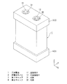
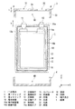
図1は、第1実施形態の電池モジュールを示す斜視図、図2は単電池カバー2と二次電池1の構成を示す分解斜視図、図3は図2のA−A’線矢視断面図である。図1に示すように、単電池カバーが取付けられた単電池により電池モジュールが構成される。なおこの電池モジュールが複数個並び、又は図10に示すように二次元的に複数個配置されて組電池が構成される。単電池カバーの説明に先立ち、まず、単電池の構成例について説明する。ここでは、積層型の二次電池について説明するが、本発明の電池モジュールの適用範囲は単電池の内部構造に限定されない。
[First Embodiment]
1 is a perspective view showing the battery module of the first embodiment, FIG. 2 is an exploded perspective view showing the configuration of the
図1〜図3に示すように、単電池としての二次電池1は、電池容器10、電極端子としての正極端子11および負極端子12を備える。電池容器10は、例えばアルミニウム製の中空容器である。本例の電池容器10は、外形が略角柱状(略直方体状)であるが、外形が円柱状であってもよい。正極端子11および負極端子12は、電池容器10の外面の1つである端子配置面10aに設けられている。正極端子11および負極端子12は、柱状(ここでは円柱状)であり、端子配置面10aの法線方向に突出している。正極端子11は、図示略の接続部(例えば高抵抗体)を介して電池容器10と電気的に接続されている。電池容器10の電位は、電池容器10がリチウムイオンと反応しないように、例えば正極端子11と略同電位に制御される。
As shown in FIGS. 1 to 3, the
以下、図1に示すXYZ座標系に基づいて構成要素の位置関係を説明する。このXYZ直交座標系において、X方向およびY方向は端子配置面10aに沿う方向であり、Z方向は端子配置面10aの法線方向である。ここでは、正極端子11、負極端子12が並ぶ方向をX方向とする。負極端子12は、正極端子11に対してX正方向側に配置されている。
Hereinafter, the positional relationship of the components will be described based on the XYZ coordinate system shown in FIG. In this XYZ orthogonal coordinate system, the X direction and the Y direction are directions along the
電池容器10内に、正極板13および負極板14がY方向に繰返し配置されている。正極板13は、負極板14と対向配置されている。正極板13と負極板14との間にセパレータ15が設けられており、正極板13が負極板14と接触しないようになっている。正極板13および負極板14は、導体箔や導体薄板からなる。セパレータ15は、例えば樹脂フィルム等の絶縁材料からなる。
A
負極板14におけるZ方向の端部には、X正方向に偏らせて負極タブ14aが形成されている。繰返し配置された複数の負極板14の負極タブ14aが一括して負極端子12と電気的に接続されている。
正極板13におけるZ方向の端部には、X負方向に偏らせて正極タブ13aが形成されている。繰返し配置された複数の正極板13の正極タブ13aが一括して正極端子11と電気的に接続されている。
A
A
電池容器10内には、リチウムイオンを含んだ電解成分が正極板13および負極板14と接触するように貯蔵される。電解成分の貯蔵形態としては、例えば電解成分を含んだ電解液を電池容器10内に貯留する形態であってもよいし、電解成分を含んだ固形物を電池容器10内に収容する形態であってもよい。リチウムイオンが電池容器10と反応しないように電池容器10の電位が制御されているので、電池容器10の合金化等が防止される。本例の電池容器10は、容器内面10bが絶縁フィルム等の絶縁膜16等により被覆されており、電解成分と絶縁されている。これにより、電池容器10の合金化を一次的に防止することができる。
In the
図1〜図3に示すように本実施形態の電池モジュールは、凹部30を有する第1キャップ3および凹部40を有する第2キャップ4からなる単電池カバーを備えている。第1キャップ3は、端子配置面10a側(Z正方向)の二次電池1の端部が凹部30に押込まれて嵌め込まれることにより、二次電池1に取付けられる。第2キャップ4は、端子配置面10aと反対側(Z負方向)の二次電池1の端部(以下、電池容器底面という)が凹部40に嵌め込まれることにより、二次電池1に取付けられる。第1キャップ3および第2キャップ4は、電池容器10との間の吸着力や摩擦力により、電池容器10から脱離しない程度に電池容器10に固定される。
As shown in FIGS. 1 to 3, the battery module of the present embodiment includes a single battery cover including a
第1キャップ3および第2キャップ4は、いずれも絶縁材料からなる。第1キャップ3や第2キャップ4の材質としては、例えば樹脂やゴム等からなり、弾性変形する材質のものがよい。弾性変形する材質を用いれば、二次電池1に密着させることが容易になる。また、樹脂やゴムを材質に用いると、第1キャップ3や第2キャップ4を型成形等により効率よく形成することができる。ここでは、第1キャップ3および第2キャップ4がシリコーンゴムからなっている。
Both the
第1キャップ3は、側部33および底部34を有し、これら2つの部位は一体形成されている。側部33は、略枠形状になっており、側部33に囲まれる部分が凹部30になっている。凹部30の開口形状(ここでは略矩形)は、端子配置面10aの外形と略一致するように設定される。凹部30開口の内寸(内周の寸法)は、端子配置面10aの外寸と同程度に設定される。
The
底部34は、第1キャップ3が二次電池1に取付けられた状態で、端子配置面10aと対向する板状の部分である。底部34には、孔部31、32が設けられている。本実施形態の孔部31、32は、底部34を貫通する貫通孔になっている。第1キャップ3が二次電池1に取付けられた状態で、孔部31内に正極端子11が位置するとともに孔部32内に負極端子12が位置するように、孔部31、32の形成位置が設定されている。ここでは、底部34の板厚tが端子高さhよりも小さい値に設定されている。第1キャップ3に二次電池1が最大押込量まで押込まれた状態、すなわち底部34が端子配置面10aと当接するまで押込まれた状態で、正極端子11の先端および負極端子12の先端が底部34の孔部から突出する。
The
以上のような構成の単電池カバー2を二次電池1に取付けると、正極端子11の側面が孔部31の内壁に囲まれるとともに、負極端子12の側面が孔部32の内壁に囲まれる。したがって、正極端子11と負極端子12とが、二次電池1と独立した導体と接触して短絡することが低減される。
When the
正極端子11の周囲および負極端子12の周囲を除いた端子配置面10aが第1キャップ3に被覆される。したがって、万一、二次電池1と独立した導体が負極端子12に接触した場合においても、この導体が端子配置面10aと接触することが低減され、電池容器10が正電位に帯電していた場合でもこの導体を介して負極端子12と短絡することが低減される。
The terminal arrangement surface 10 a excluding the periphery of the
二次電池1の端子配置面10aが電極端子部分を除いて第1キャップ3に被覆され、かつ電池容器底面が第2キャップ4に被覆されるので、第1キャップ3と第2キャップ4を取り付けた二次電池1を載置した場合に、二次電池1と独立した導体が電池容器10に接触しにくくなる。
例えば、端子配置面10a以外のいずれかの面を作業台等のテーブル表面に向けて置いたとする。第1キャップ3の側部33や第2キャップ4が、電池容器10の表面と作業台の表面との間にスペースを設けるので、作業台の表面が導電性を有していても電池容器10と作業台表面との間で短絡することが防止される。
Since the
For example, it is assumed that any surface other than the
以上のように、第1実施形態の電池モジュールによれば、正極端子11と負極端子12との短絡が防止することができ、短絡による発熱や電荷ロスを防止することができる。これにより、二次電池1の充電率等を高精度に管理することが可能になり、二次電池1を良好な特性で機能させることができる。
As described above, according to the battery module of the first embodiment, a short circuit between the
また、正極端子11に電気的に接続された電池容器10と負極端子12との短絡を防止することや、二次電池1と独立した導体(ゴミなど)と電池容器10との短絡を防止することができる。したがって、電池容器10の電位を所望の値に制御することができ、電池容器10とリチウムイオンとの反応を防止することができる。よって、電池容器10が合金化することによる特性変化や、電解成分が劣化することによる特性変化等を防止することができ、二次電池1を良好に機能させることができる。
Further, a short circuit between the
また、第1実施形態の電池モジュールは、搬送時や設置時、複数の電池モジュールを組み合わせてなる組電池の組立て時等において、電池モジュール間の短絡を防止することができるので、ハンドリング性が良好なものになる。 In addition, the battery module according to the first embodiment can prevent short-circuiting between battery modules at the time of transportation, installation, assembly of a battery pack in which a plurality of battery modules are combined, etc., and thus has good handling properties. It will be something.
[第2実施形態]
次に、図4(a)、(b)を参照しつつ、第2実施形態に係る電池モジュールについて説明する。図4(a)は単電池カバーの概略構成を示す側断面図、図4(b)は単電池カバーの使用方法を示す説明図である。図4(a)には、図3に対応する断面の一部を図示している。
[Second Embodiment]
Next, the battery module according to the second embodiment will be described with reference to FIGS. 4 (a) and 4 (b). FIG. 4A is a side sectional view showing a schematic configuration of the unit cell cover, and FIG. 4B is an explanatory diagram showing a method of using the unit cell cover. FIG. 4A shows a part of a cross section corresponding to FIG.
図4(a)、(b)に示すように、第2実施形態の電池モジュールが第1実施形態と異なる点は、電極端子(正極端子11、負極端子12)を上記ゴミなどの付着から保護する保護部としての第3キャップ5を備える点である。第3キャップ5は、孔部32に押込まれて、第1キャップ3に着脱可能に取付けられる。第3キャップ5は、凹部50を有している。第3キャップ5が第1キャップ3に取付けられた状態で、負極端子12は凹部50内に収容され、外部に露出しないようになっている。
As shown in FIGS. 4A and 4B, the battery module of the second embodiment is different from the first embodiment in that the electrode terminals (the
第2実施形態における単電池カバーは、例えば以下のようにして使用される。まず、二次電池1を用意し、二次電池1に第1キャップ3を取付けた後、第1キャップ3の負極端子側の孔部32に第3キャップ5を取付ける。また、必要に応じて二次電池1に第2キャップ4を取付ける。そして、単電池カバーが取付けられた二次電池1を所定の位置に搬送し、設置する。そして、第3キャップ5を取外して負極端子12を露出させ、正極端子11や負極端子12をデバイス等に接続して二次電池1を機能させる。
The cell cover in the second embodiment is used as follows, for example. First, after preparing the
第2実施形態の電池モジュールは、負極端子12を第3キャップ5で被覆することができ、負極端子12が正極端子11や電池容器10、二次電池1と独立した導体等と短絡することが確実に防止される。二次電池1を使用する際には、第3キャップ5を取外すことにより、負極端子12を外部に露出させることができ、負極端子12を外部に容易に接続することができる。
なお、正極端子11を被覆するように第3キャップ5を取付けてもよいし、正極端子11と負極端子12とにそれぞれ第3キャップ5を取付けてもよい。
In the battery module of the second embodiment, the
The
[第3実施形態]
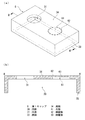
次に、図5(a)、(b)、図6(a)〜(c)を参照しつつ、第3実施形態に係る電池モジュールについて説明する。図5(a)は単電池カバーを構成する第1キャップの概略構成を示す斜視図、図5(b)は図5(a)のB−B’線矢視断面図、図6(a)〜(c)は単電池カバーの使用方法を示す説明図である。
[Third Embodiment]
Next, the battery module according to the third embodiment will be described with reference to FIGS. 5 (a), 5 (b), and FIGS. 6 (a) to 6 (c). FIG. 5A is a perspective view showing a schematic configuration of the first cap constituting the unit cell cover, FIG. 5B is a cross-sectional view taken along line BB ′ in FIG. 5A, and FIG. (C) is explanatory drawing which shows the usage method of a cell cover.
図5(a)、(b)に示すように、第3実施形態の電池モジュールは、第1キャップ6と第1実施形態の第2キャップ4とからなる。第3実施形態の第1キャップ6が第1実施形態と異なる点は、第1キャップ6が、電極端子(特に負極端子)を上記ゴミなどの付着から保護する保護部63を備える点である。第1キャップ6の底部34には、孔部31、61が設けられている。孔部61は底部34を貫通しないように形成されており。孔部61の底部が保護部63になっている。保護部63において負極端子12の先端と接触する部分の周囲(ここでは保護部63の周縁部)に、破断部62が設けられている。
As shown in FIGS. 5A and 5B, the battery module of the third embodiment includes a
本実施形態の破断部62は、貫通孔が間欠的に設けられたミシン目状のものであり、保護部63内で相対的に破断されやすくなっている。第1キャップ6は、型成形等により形成されており、孔部31、61および破断部62は一括して形成(一体成形)されている。
The breaking
第3実施形態における単電池カバーは、例えば以下のようにして使用される。まず、二次電池1を用意し、二次電池1において負極端子12を備えた電極端部を第1キャップ6の凹部30に押込む。凹部30に電極端部を押込む深さ(押込量)を増すと、負極端子12の先端が保護部63に到達する。ここでは、保護部63が破断されない程度に凹部30に電極端部を押込む。第1キャップ6と電池容器10との摩擦力等により、第1キャップ6が二次電池1を仮止めする。
The cell cover in the third embodiment is used as follows, for example. First, the
そして、単電池カバーが仮止めされた二次電池1を所定の位置に搬送し、設置する。そして、最大押込量まで電池端部を凹部30に押込む。押込量が第1キャップ6の材質等により定まる所定値以上になると、保護部63に作用するせん断力により破断部62が破断される。破断部62を破断することにより保護部63を底部34から切取って除去し、負極端子12を露出させる。そして、正極端子11や負極端子12をデバイス等に接続して二次電池1を機能させる。
Then, the
第3実施形態の電池モジュールでは、負極端子12を保護部63で被覆することができ、負極端子12が正極端子11や電池容器10、二次電池1と独立した導体等と短絡することが確実に防止される。二次電池1を使用する際には、保護部63を切取ることにより、負極端子12を外部に露出させることができ、負極端子12を外部に容易に接続することができる。
In the battery module of the third embodiment, the
なお、保護部63としては様々な変形が可能である。例えば、保護部63が孔部31に設けられていてもよいし、孔部31、32にそれぞれ設けられていてもよい。二次電池1の使用時に保護部63を完全に除去するのではなく、保護部63の一部が第1キャップ6と連続した状態で例えば保護部63をめくることにより負極端子12を外部に露出させてもよい。以下、保護部63の変形例について説明する。
Various modifications can be made to the
図7(a)は、変形例1の第1キャップ6Bの概略構成を示す断面図、図7(b)は変形例2の第1キャップ6Cを示す平面図である。
図7(a)に示すように、第1キャップ6Bの保護部63の周縁部は、破断部62になっている。破断部62の肉厚は、破断部62以外の保護部63の肉厚よりも薄くなっている。これにより、破断部62は、保護部63内で相対的に破断されやすくなる。
FIG. 7A is a cross-sectional view illustrating a schematic configuration of the
As shown in FIG. 7A, the peripheral portion of the
図7(b)に示すように、第1キャップ6Cの孔部61の底部には、凹部30に連通するスリット64が設けられている。ここでは、スリット64の形状が略十字状になっている。スリット64の内寸は、負極端子12が通らない程度に小さく設定されている。スリット64周辺における孔部61の底部が保護部63になっている。なおスリット64の形状は略十字状に限定されず、例えば円状や三角などの多角状であってもよい。
As shown in FIG. 7B, a
保護部63に負極端子12の先端が接触しない程度の押込量で、電極端部を第1キャップ6Cの凹部に二次電池1を押込むと、負極端子12の先端の一部は、保護部63に被覆されて外部から保護される。押込量を増すと、保護部63が負極端子12に押圧されて負極端子12と反対側に変形し、スリット64が負極端子12の先端により押し広げられる。これにより、負極端子12を外部に露出させることができる。このように、保護部としては、負極端子12の先端の少なくとも一部を覆うものであればよく、また第1キャップから切り取らないで使用するものであってもよい。
When the
[第4実施形態]
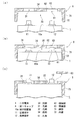
次に、図8(a)〜(c)を参照しつつ、第4実施形態に係る電池モジュールについて説明する。図8(a)は、単電池カバーの概略構成を示す側断面図、図8(b)、(c)は、単電池カバーの使用方法を示す説明図である。図8(a)には、図3に対応する断面の一部を図示している。
[Fourth Embodiment]
Next, the battery module which concerns on 4th Embodiment is demonstrated, referring Fig.8 (a)-(c). FIG. 8A is a side sectional view showing a schematic configuration of the unit cell cover, and FIGS. 8B and 8C are explanatory views showing a method of using the unit cell cover. FIG. 8A shows a part of a cross section corresponding to FIG.
図8(a)〜(c)に示すように、第4実施形態における単電池カバーは第1キャップ7と第1実施形態の第2キャップ4とからなる。第1キャップ7が第1実施形態と異なる点は、第1キャップ7の凹部30の内壁72がテーパー形状になっている点である。内壁72は、第1キャップ7の側部71のうち、凹部30に面する部分である。凹部30の開口における内周の寸法である内壁72の開口内寸d1は、底部34との境界における凹部30の内周の寸法である内壁72の底部内寸d2よりも大きくなっている。電池容器10の端子配置面10aの外周の寸法を電池端部の外寸d0とすると、d1がd0より大きく設定されているとともにd2がd0未満に設定されている。すなわち、d2<d0<d1である。
As shown in FIGS. 8A to 8C, the cell cover in the fourth embodiment includes a
内壁72の内周の寸法が電池端部の外寸d0と略一致するまで第1キャップ7に電池端部を押込んだ状態において、底部34と端子配置面10aとのギャップをd3とする(図8(b)参照)。ギャップd3と、端子高さhと、底部34の板厚tとの間に(d3+t>h)という関係が成り立つように、内壁72の形状が設定されている。すなわち、端子配置面10aが内壁72に接触するまで電池端部を第1キャップ7に押込んだ状態で、正極端子11および負極端子12が孔部を通過して第1キャップ7から突出しないようになっている。
The inner peripheral dimension I pushed the cell edge to the outer dimension d 0 and approximately the
第4実施形態における単電池カバーは、例えば以下のようにして使用される。まず、二次電池1を用意し、二次電池1において負極端子12を含んだ電極端部を第1キャップ7の凹部30に押込む。ここでは、端子配置面10aの外周全体が内壁72に接触するまで押込み、さらに押込量を増すことにより負極端子12の先端が孔部32を通過しない程度まで押込む。これにより、内壁72が電池端部により押し広げられ、電池端部が側部71により締め付けられることにより、二次電池1に第1キャップ7が仮止めされる。
The cell cover in the fourth embodiment is used as follows, for example. First, the
そして、単電池カバーが仮止めされた二次電池1を所定の位置に搬送、設置する。そして、最大押込量まで電池端部を凹部30に押込むことにより正極端子11および負極端子12を露出させ、正極端子11や負極端子12をデバイス等に接続して二次電池1を機能させる。
Then, the
第4実施形態の電池モジュールは、第1キャップ7が仮止めされた状態では負極端子12が孔部を通過することがなく、すなわち負極端子12が第1キャップ7から突出しないので、負極端子12が電池容器10や正極端子11、二次電池1と独立した導体等と短絡することが確実に防止される。また、側部71の弾性力により第1キャップ7が二次電池1に仮止めされるので、第1キャップ7が脱離することが防止される。二次電池1を使用する際には、押込量を増すことにより、負極端子12を第1キャップ7から突出させて第1キャップ7を二次電池1に固定することができ、負極端子12を外部に容易に接続することができる。
第4実施形態の電池モジュールは、負極端子12の短絡が防止され、しかも第1キャップ7の脱離が防止されるので、ハンドリング性が格段に高くなる。
In the battery module of the fourth embodiment, when the
In the battery module of the fourth embodiment, the short-circuit of the
[第5実施形態]
次に、図9(a)〜(c)を参照しつつ、第5実施形態に係る電池モジュールについて説明する。図9(a)は、単電池カバーの概略構成を示す側断面図、図9(b)、(c)は、単電池カバーの使用方法を示す説明図である。図9(a)には、図3に対応する断面の一部を図示している。
[Fifth Embodiment]
Next, the battery module according to the fifth embodiment will be described with reference to FIGS. Fig.9 (a) is a sectional side view which shows schematic structure of a cell cover, FIG.9 (b), (c) is explanatory drawing which shows the usage method of a cell cover. FIG. 9A shows a part of a cross section corresponding to FIG.
図9(a)〜(c)に示すように、第5実施形態における単電池カバーが第4実施形態と異なる点は、第1キャップ8が保護部63を備える点である。保護部63は、第3実施形態で説明したものと同様のものである(図5参照)。
As shown in FIGS. 9A to 9C, the cell cover in the fifth embodiment is different from the fourth embodiment in that the
第1キャップ8の底部34には、孔部31、61が設けられている。孔部61は底部34を貫通しないように形成されており。孔部61の底部が保護部63になっている。保護部63の周縁部に、破断部62が設けられている。第1キャップ8の凹部30の内壁72は、第4実施形態と同様にテーパー形状になっている。
第5実施形態における単電池カバーは、例えば以下のようにして使用される。まず、二次電池1を用意し、二次電池1において負極端子12を含んだ電極端部を第1キャップ8の凹部30に押込む。ここでは、端子配置面10aの外周全体が内壁72に接触するまで押込み、さらに押込量を増すことにより負極端子12の先端が保護部63に接触しない程度まで押込む。電池端部が側部71により締め付けられることにより、二次電池1に第1キャップ8が仮止めされる。
The cell cover in the fifth embodiment is used as follows, for example. First, the
そして、単電池カバーが仮止めされた二次電池1を所定の位置に搬送、設置する。そして、押込量を増すことにより負極端子12の先端で保護部63を押圧して保護部63にせん断力を作用させ、せん断力により破断部62を破断する。そして、保護部63を除去することにより負極端子12を露出させ、正極端子11や負極端子12をデバイス等に接続して二次電池1を機能させる。
Then, the
第5実施形態の電池モジュールは、第1キャップ8が仮止めされた状態で負極端子12が保護部63により覆われており外部に露出していないので、負極端子12が電池容器10や正極端子11、二次電池と独立した導体等と短絡することが確実に防止される。側部71の弾性力により第1キャップ8が二次電池1に仮止めされるので、第1キャップ8が脱離することが防止される。また、第1キャップ8が仮止めされた状態で予期せぬ外力等による押込量の変化が抑制されるので、仮に押込量が不測に増加しても、破断部62が破断してしまうことが防止される。二次電池1を使用する際には、押込量を増すことにより破断部62を破断して保護部63除去し、負極端子12が孔部を通過し第1キャップ8から突出させて第1キャップ8を二次電池1に固定することができる。これにより、負極端子12を外部に容易に接続することができる。
In the battery module of the fifth embodiment, since the
[第6実施形態]
次に、図10を参照しつつ、第6実施形態に係る組電池について説明する。図10は、第6実施形態の組電池9の概略構成を示す分解斜視図である。図10に示すように、組電池9は、複数の電池モジュール90、パッケージ(組電池容器)91および配線板92を備える。電池モジュール90の単電池カバーとしては、第1〜第5実施形態で説明したいずれの単電池カバーを用いてもよく、ここでは第1実施形態における単電池カバーを採用している。電池モジュール90は、二次電池1、第1キャップ3、第2キャップ4を備える。
[Sixth Embodiment]
Next, the assembled battery according to the sixth embodiment will be described with reference to FIG. FIG. 10 is an exploded perspective view showing a schematic configuration of the assembled
本実施形態の複数の電池モジュール90は、二次元的に配列されてパッケージ91に収容されている。パッケージ91は絶縁材料で形成されることが望ましく、中でも成形容易のためプラスチック樹脂が望ましい。パッケージ91は、複数の電池モジュール90の相対位置を固定する枠体として機能する。また、電池モジュール90を配列する際、第1キャップ3および第2キャップ4は隣接する電池モジュール90とのスペーサとなり、隣接する電池モジュール間の電気的短絡を防止することができ、さらに電池容器を全て覆っているわけではないので放熱効果も期待できる。本実施形態では、正極端子11および負極端子12が突出する方向が、複数の電池モジュール90で揃うように、複数の電池モジュール90が配列されている。
The plurality of
配線板92は、複数の電池モジュール90の正極端子11および負極端子12と接触するように設けられている。配線板92はパッケージ91と同様の絶縁材料で形成されており、ここには複数の配線93が埋め込まれ又はプリントされて配置されている。ここでは、配線93の各々が、1つの電池モジュール90の正極端子11と、この電池モジュール90にY方向で隣接する電池モジュール90の負極端子12とを電気的に接続するようになっている。すなわち、1つの配列方向(Y方向)に並ぶ電池モジュール90が、直列に接続されている。配線板92はパッケージ91の蓋を兼ねてもよい。この場合には、配線板92とパッケージ91とを嵌合することで、複数の電池モジュール90が密閉されて収容される。配線板92をパッケージ91と嵌合することで、複数の電池モジュール90の各々の正極端子および負極端子が複数の配線93の所定位置にそれぞれ自動的に電気接続される。
The
以上のような構成の組電池9にあっては、第1〜第5実施形態で説明したように、電池モジュール90の短絡が防止される。また、複数の電池モジュール90の電池容器10同士の接触・短絡や、ある電池モジュール90の電池容器とそれと異なる電池モジュール90の負極端子12との短絡が防止される。したがって、例えば、リチウムイオン二次電池において正極と電池容器とが上記接続部を介して接続されることで同電位にされている場合に、電池容器10の合金化等による電池モジュール90の特性低下が防止され、複数の電池モジュール90における特性ばらつきが低減される。電池モジュール90の特性低下が防止されるので組電池9全体としての特性が良好になる。また、特性ばらつきが低減されるので、電池モジュール90ごとの充電率等を高精度に管理することが可能になり、組電池9全体としての特性が良好になる。
In the assembled
なお、本発明の技術範囲は前記実施形態に限定されるものではない。本発明の主旨を逸脱しない範囲内で多様な変形が可能である。
例えば、単電池カバーは少なくとも第1キャップを備えていればよい。第2キャップが設けられていなくとも、第1キャップを用いることにより電極端子の短絡を防止する効果が得られる。単電池カバーが、キャップの他に各種付帯物を備えていてもよい。各種付帯物は、例えば第1キャップと第2キャップとを連結する部材、例えば一端を第1キャップに接続し他端を第2キャップに接続した絶縁性テープ等である。かように連結することで、第1キャップまたは第2キャップが電池容器からはずれることを防止できる。
第1キャップは、二次電池の少なくとも電池端部に被着されるものであればよい。二次電池1の放熱を重視しなくともよい使用状態において、単電池カバーを使用する場合には、第1キャップの側部が電池容器の側方全体を覆うようになっていてもよい。
電池容器10を正極端子11と電気的に接続する接続部が電池容器10の外部に設けられている場合には、必要に応じて第1キャップに接続部の逃げ部を形成しておくとよい。
二次電池に第1キャップを取付けた状態で、電極端子が孔部を通過しないように、すなわち第1キャップから正極端子の先端や負極端子先端が突出しないように底部34の厚みを調整してもよい。この場合に例えば正極端子を外部と接続するには、第1キャップの孔部内に収まる接続端子を有する接続部品を介して正極端子を外部と電気的に接続することができる。負極端子の接続については、正極端子と同様である。
The technical scope of the present invention is not limited to the above embodiment. Various modifications are possible without departing from the gist of the present invention.
For example, the unit cell cover only needs to include at least the first cap. Even if the second cap is not provided, the effect of preventing a short circuit of the electrode terminal can be obtained by using the first cap. The single battery cover may include various incidental objects in addition to the cap. The various accessories are, for example, members that connect the first cap and the second cap, such as an insulating tape having one end connected to the first cap and the other end connected to the second cap. By connecting in this way, it can prevent that a 1st cap or a 2nd cap remove | deviates from a battery container.
The 1st cap should just be attached to the battery edge part at least of a secondary battery. In the state of use in which the heat dissipation of the
When the connection part which electrically connects the
With the first cap attached to the secondary battery, the thickness of the bottom 34 is adjusted so that the electrode terminal does not pass through the hole, that is, the tip of the positive electrode terminal or the tip of the negative electrode terminal does not protrude from the first cap. Also good. In this case, for example, in order to connect the positive electrode terminal to the outside, the positive electrode terminal can be electrically connected to the outside through a connection component having a connection terminal that fits in the hole of the first cap. The connection of the negative terminal is the same as that of the positive terminal.
1・・・二次電池(単電池)、2・・・単電池カバー、
3・・・第1キャップ(キャップ)、4・・・第2キャップ、5・・・第3キャップ(保護部)、6、6B、6C、7、8・・・第1キャップ、9・・・組電池、10・・・電池容器、10a・・・端子配置面、10b・・・容器内面、11・・・正極端子、
12・・・負極端子、13・・・正極板、13a・・・正極タブ、14・・・負極板、
14a・・・負極タブ、15・・・セパレータ、16・・・絶縁膜、30・・・凹部、
31、32・・・孔部、33・・・側部、34・・・底部、40、50・・・凹部、
61・・・孔部、62・・・破断部、63・・・保護部、64・・・スリット、
71・・・側部、72・・・内壁、90・・・電池モジュール、91・・・パッケージ、
92・・・配線板、93・・・配線、d0・・・外寸、d1・・・開口内寸、
d2・・・底部内寸、d3・・・ギャップ、h・・・端子高さ、t・・・板厚
1 ... secondary battery (single cell), 2 ... single cell cover,
3 ... 1st cap (cap), 4 ... 2nd cap, 5 ... 3rd cap (protection part), 6, 6B, 6C, 7, 8 ... 1st cap, 9 ... Battery assembly, 10 ... battery container, 10a ... terminal arrangement surface, 10b ... inner surface, 11 ... positive electrode terminal,
12 ... Negative electrode terminal, 13 ... Positive electrode plate, 13a ... Positive electrode tab, 14 ... Negative electrode plate,
14a ... negative electrode tab, 15 ... separator, 16 ... insulating film, 30 ... recess,
31, 32 ... hole, 33 ... side, 34 ... bottom, 40, 50 ... recess,
61 ... hole, 62 ... breaking part, 63 ... protection part, 64 ... slit,
71 ... side part, 72 ... inner wall, 90 ... battery module, 91 ... package,
92 ... wiring
d 2 ... bottom inside dimension, d 3 ... gap, h ... terminal height, t ... plate thickness
Claims (4)
前記正極端子および前記負極端子に対応して孔部が形成され、且つ前記負極端子を含む前記電池の端部を覆う絶縁部材からなるキャップと、
少なくとも一方の前記孔部を塞ぐ保護部と、
を有し、
前記キャップが前記電池の端部に所定の押込量以上まで押込まれることにより、前記正極端子または前記負極端子が前記保護部を抜けて前記キャップから突出することを特徴とする電池モジュール。 A battery comprising a positive terminal, a negative terminal and a battery container;
A cap formed of an insulating member that has a hole corresponding to the positive electrode terminal and the negative electrode terminal and covers an end of the battery including the negative electrode terminal;
A protective part that closes at least one of the holes;
Have
The battery module, wherein when the cap is pushed into an end portion of the battery to a predetermined pushing amount or more, the positive terminal or the negative terminal protrudes from the cap through the protective portion.
絶縁部材からなる第1および第2のキャップと、を有し、
前記第1のキャップは前記第1の電池の端部を覆い、前記第2のキャップは前記第2の電池の端部を覆い、前記第1のキャップと第2のキャップが接して配置され、
前記第1および第2のキャップの各々は、それぞれ前記正極端子および前記負極端子に対応した孔部と、少なくとも前記負極端子に対応した前記孔部に配置される保護部と、をさらに有し、
前記第1および第2のキャップのそれぞれが、対応する前記第1および第2の電池の端部に向けて所定の押込量以上まで押込まれることにより、それぞれの前記負極端子がそれぞれの前記保護部を抜けて、対応する前記第1および第2のキャップから突出することを特徴とする電池モジュール。 First and second batteries comprising a positive electrode terminal, a negative electrode terminal and a battery container, wherein the battery container and the positive electrode terminal are electrically connected;
A first cap and a second cap made of an insulating member;
The first cap covers an end portion of the first battery, the second cap covers an end portion of the second battery, and the first cap and the second cap are disposed in contact with each other ;
Each of the first and second caps further includes a hole corresponding to the positive electrode terminal and the negative electrode terminal, respectively, and a protection part disposed at least in the hole corresponding to the negative electrode terminal,
Each of the first and second caps is pushed to a corresponding pushing amount or more toward the corresponding end of the first and second batteries, so that each of the negative terminals is protected by the protection. A battery module that protrudes from the corresponding first and second caps through the portion .
複数の配線が埋め込まれまたはプリントされた配線板と、を有し、
前記配線板を前記パッケージと嵌合することで、前記複数の電池モジュールの各々の正極端子および負極端子が前記複数の配線の所定位置にそれぞれ電気的に接続されることを特徴とする組電池。 A package for storing two or more two-dimensionally arranged battery modules according to any one of claims 1 to 3 ;
A wiring board in which a plurality of wirings are embedded or printed,
The assembled battery, wherein the positive electrode terminal and the negative electrode terminal of each of the plurality of battery modules are electrically connected to predetermined positions of the plurality of wirings by fitting the wiring board with the package.
Priority Applications (7)
| Application Number | Priority Date | Filing Date | Title |
|---|---|---|---|
| JP2009292306A JP5237253B2 (en) | 2009-12-24 | 2009-12-24 | Battery module and battery pack |
| PCT/JP2010/073170 WO2011078241A1 (en) | 2009-12-24 | 2010-12-22 | Battery module and assembled battery |
| US13/389,477 US20120141861A1 (en) | 2009-12-24 | 2010-12-22 | Battery module and assembled battery |
| EP10839471.9A EP2463938A4 (en) | 2009-12-24 | 2010-12-22 | Battery module and assembled battery |
| CN2010900010672U CN202817079U (en) | 2009-12-24 | 2010-12-22 | Battery module and assembled battery |
| TW099145314A TWI431838B (en) | 2009-12-24 | 2010-12-22 | Cell module and assembled battery |
| KR1020127003292A KR101345477B1 (en) | 2009-12-24 | 2010-12-22 | Battery module and assembled battery |
Applications Claiming Priority (1)
| Application Number | Priority Date | Filing Date | Title |
|---|---|---|---|
| JP2009292306A JP5237253B2 (en) | 2009-12-24 | 2009-12-24 | Battery module and battery pack |
Publications (2)
| Publication Number | Publication Date |
|---|---|
| JP2011134552A JP2011134552A (en) | 2011-07-07 |
| JP5237253B2 true JP5237253B2 (en) | 2013-07-17 |
Family
ID=44195768
Family Applications (1)
| Application Number | Title | Priority Date | Filing Date |
|---|---|---|---|
| JP2009292306A Expired - Fee Related JP5237253B2 (en) | 2009-12-24 | 2009-12-24 | Battery module and battery pack |
Country Status (7)
| Country | Link |
|---|---|
| US (1) | US20120141861A1 (en) |
| EP (1) | EP2463938A4 (en) |
| JP (1) | JP5237253B2 (en) |
| KR (1) | KR101345477B1 (en) |
| CN (1) | CN202817079U (en) |
| TW (1) | TWI431838B (en) |
| WO (1) | WO2011078241A1 (en) |
Families Citing this family (26)
| Publication number | Priority date | Publication date | Assignee | Title |
|---|---|---|---|---|
| JP5155772B2 (en) * | 2008-08-19 | 2013-03-06 | 三菱重工業株式会社 | Battery pack structure |
| JP5271890B2 (en) * | 2009-12-24 | 2013-08-21 | 三菱重工業株式会社 | Battery module and battery pack |
| JP5222335B2 (en) * | 2010-09-22 | 2013-06-26 | 三菱重工業株式会社 | Battery module and battery system |
| JP4939643B1 (en) * | 2010-11-09 | 2012-05-30 | 三菱重工業株式会社 | Battery module |
| US20120313585A1 (en) * | 2011-02-07 | 2012-12-13 | Frank Pereira | Device for lithium ion battery storage and transportation |
| CN102420297A (en) * | 2011-12-02 | 2012-04-18 | 苏州冠硕新能源有限公司 | Battery module frame and battery pack employing battery module frame |
| CN102420303A (en) * | 2011-12-02 | 2012-04-18 | 苏州冠硕新能源有限公司 | Battery assembly |
| JP5945435B2 (en) * | 2012-03-16 | 2016-07-05 | 本田技研工業株式会社 | Battery module |
| JP6098105B2 (en) * | 2012-10-22 | 2017-03-22 | 日立化成株式会社 | Storage structure for electricity storage devices |
| KR101602012B1 (en) * | 2013-01-18 | 2016-03-17 | 주식회사 엘지화학 | Secondary battery structure |
| CN104143610B (en) * | 2013-07-24 | 2017-04-26 | 中航锂电(洛阳)有限公司 | Battery protection cover and battery pack using the same |
| JP6168986B2 (en) * | 2013-12-25 | 2017-07-26 | 株式会社東芝 | Battery module |
| CN106575721B (en) * | 2014-09-03 | 2020-06-12 | 日本汽车能源株式会社 | Square secondary battery |
| CN105405988A (en) | 2014-09-04 | 2016-03-16 | 株式会社杰士汤浅国际 | Energy Storage Apparatus And Method Of Manufacturing Energy Storage Apparatus |
| JP6759534B2 (en) | 2014-09-04 | 2020-09-23 | 株式会社Gsユアサ | Power storage device |
| WO2016104133A1 (en) * | 2014-12-26 | 2016-06-30 | シャープ株式会社 | Battery module and power generation system |
| US10734617B2 (en) * | 2015-07-22 | 2020-08-04 | Murata Manufacturing Co., Ltd. | Battery module, power tool, and electronic apparatus |
| JP6613773B2 (en) * | 2015-09-30 | 2019-12-04 | 株式会社Gsユアサ | Power storage device |
| KR102484264B1 (en) * | 2015-11-24 | 2023-01-02 | 삼성에스디아이 주식회사 | Secondary battery and fabricating method thereof |
| WO2018049344A1 (en) * | 2016-09-12 | 2018-03-15 | Valence Technology, Inc. | Rechargeable battery modules and rechargeable battery module handling methods |
| CN106450049A (en) * | 2016-10-24 | 2017-02-22 | 宁德时代新能源科技股份有限公司 | Battery and battery module |
| KR200487443Y1 (en) * | 2017-04-26 | 2018-09-17 | 대린전자(주) | The cap for protect with array type in capacitor |
| EP3762983A1 (en) | 2018-03-05 | 2021-01-13 | CPS Technology Holdings LLC | Cap for battery terminal |
| US20210057693A1 (en) * | 2018-05-11 | 2021-02-25 | Hitachi Chemical Company, Ltd. | Metallic accommodating frame for lead storage battery, battery pack, and method for preventing ground fault |
| JP6808903B2 (en) * | 2018-11-09 | 2021-01-06 | 矢崎総業株式会社 | Battery module and battery pack |
| JP2020155283A (en) * | 2019-03-19 | 2020-09-24 | 株式会社Gsユアサ | Power storage element and power storage device |
Family Cites Families (12)
| Publication number | Priority date | Publication date | Assignee | Title |
|---|---|---|---|---|
| US3884725A (en) * | 1974-02-15 | 1975-05-20 | Mc Graw Edison Co | Battery with post-strap insulative cap |
| GB1558223A (en) * | 1977-06-22 | 1979-12-19 | Heatherbourne Plastics Ltd | Protective cover for a storage battery |
| US5015543A (en) * | 1990-08-31 | 1991-05-14 | General Motors Corporation | Battery terminal cap |
| JP2591624Y2 (en) * | 1992-11-06 | 1999-03-10 | 富士電気化学株式会社 | Battery pack |
| JP3977964B2 (en) * | 1999-09-21 | 2007-09-19 | 松下電器産業株式会社 | Battery connection structure |
| JP4733248B2 (en) * | 2000-06-20 | 2011-07-27 | 本田技研工業株式会社 | Cell module structure |
| JP2003045498A (en) | 2001-08-02 | 2003-02-14 | Mitsubishi Heavy Ind Ltd | Secondary battery and method and device for manufacturing it |
| JP4182337B2 (en) * | 2002-12-19 | 2008-11-19 | 株式会社ジーエス・ユアサコーポレーション | Assembled battery |
| JP4718812B2 (en) * | 2004-09-06 | 2011-07-06 | Necエナジーデバイス株式会社 | Secondary battery pack |
| JP4716795B2 (en) * | 2005-06-07 | 2011-07-06 | 三洋電機株式会社 | Pack battery |
| JP5271498B2 (en) | 2007-01-26 | 2013-08-21 | 三菱重工業株式会社 | Lithium secondary battery and battery pack |
| JP2009292306A (en) | 2008-06-05 | 2009-12-17 | Jtekt Corp | Shock-absorbing steering device |
-
2009
- 2009-12-24 JP JP2009292306A patent/JP5237253B2/en not_active Expired - Fee Related
-
2010
- 2010-12-22 CN CN2010900010672U patent/CN202817079U/en not_active Expired - Fee Related
- 2010-12-22 TW TW099145314A patent/TWI431838B/en not_active IP Right Cessation
- 2010-12-22 KR KR1020127003292A patent/KR101345477B1/en not_active IP Right Cessation
- 2010-12-22 WO PCT/JP2010/073170 patent/WO2011078241A1/en active Application Filing
- 2010-12-22 EP EP10839471.9A patent/EP2463938A4/en not_active Withdrawn
- 2010-12-22 US US13/389,477 patent/US20120141861A1/en not_active Abandoned
Also Published As
| Publication number | Publication date |
|---|---|
| TW201145644A (en) | 2011-12-16 |
| KR20120041749A (en) | 2012-05-02 |
| EP2463938A4 (en) | 2013-09-18 |
| JP2011134552A (en) | 2011-07-07 |
| CN202817079U (en) | 2013-03-20 |
| EP2463938A1 (en) | 2012-06-13 |
| KR101345477B1 (en) | 2013-12-27 |
| TWI431838B (en) | 2014-03-21 |
| WO2011078241A1 (en) | 2011-06-30 |
| US20120141861A1 (en) | 2012-06-07 |
Similar Documents
| Publication | Publication Date | Title |
|---|---|---|
| JP5237253B2 (en) | Battery module and battery pack | |
| KR102052588B1 (en) | Rechargeable battery pack | |
| US11594776B2 (en) | Battery module including heat shrinkable tube | |
| CN101557012B (en) | Battery pack | |
| JP5271890B2 (en) | Battery module and battery pack | |
| KR101023922B1 (en) | Cylindrical Secondary Battery Pack | |
| KR101440890B1 (en) | Battery Pack | |
| EP2395575B1 (en) | Battery pack | |
| KR101776897B1 (en) | Pouch type secondary battery and method for manufacturing the same | |
| EP2978061B1 (en) | Pouch-type secondary battery and secondary battery module comprising same | |
| EP2602841A1 (en) | Battery | |
| KR20150037154A (en) | Battery Pack Having PCM Case | |
| KR102384308B1 (en) | Pouch-type Battery Cell Having Venting Member and Battery Pack Comprising the Same | |
| KR102066197B1 (en) | Battery module and battery pack including the same | |
| CN106549133B (en) | Secondary battery | |
| KR101797694B1 (en) | Battery Pack Having Small PCM | |
| KR20180122844A (en) | Battery pack and method for manufcturing the same | |
| KR20150046533A (en) | Pouch type secondary battery and battery pack including the same | |
| KR102216744B1 (en) | Battery cell, and battery module | |
| JP2006073457A (en) | Secondary battery pack | |
| KR101189621B1 (en) | Secondary battery with improved safety | |
| KR102379765B1 (en) | The Secondary Battery And The Battery Module | |
| KR20160054268A (en) | Secondary battery cell and battery module including the same | |
| KR101749720B1 (en) | Battery Pack Having a Integrated Case Member | |
| KR101783920B1 (en) | Battery lead to be connected to cable and manufacturing method thereof |
Legal Events
| Date | Code | Title | Description |
|---|---|---|---|
| A131 | Notification of reasons for refusal |
Free format text: JAPANESE INTERMEDIATE CODE: A131 Effective date: 20121113 |
|
| A521 | Request for written amendment filed |
Free format text: JAPANESE INTERMEDIATE CODE: A523 Effective date: 20121220 |
|
| A521 | Request for written amendment filed |
Free format text: JAPANESE INTERMEDIATE CODE: A821 Effective date: 20121221 |
|
| TRDD | Decision of grant or rejection written | ||
| A01 | Written decision to grant a patent or to grant a registration (utility model) |
Free format text: JAPANESE INTERMEDIATE CODE: A01 Effective date: 20130305 |
|
| A61 | First payment of annual fees (during grant procedure) |
Free format text: JAPANESE INTERMEDIATE CODE: A61 Effective date: 20130328 |
|
| FPAY | Renewal fee payment (event date is renewal date of database) |
Free format text: PAYMENT UNTIL: 20160405 Year of fee payment: 3 |
|
| LAPS | Cancellation because of no payment of annual fees |