EP3173628A1 - Blower and air conditioning machine - Google Patents
Blower and air conditioning machine Download PDFInfo
- Publication number
- EP3173628A1 EP3173628A1 EP14898317.4A EP14898317A EP3173628A1 EP 3173628 A1 EP3173628 A1 EP 3173628A1 EP 14898317 A EP14898317 A EP 14898317A EP 3173628 A1 EP3173628 A1 EP 3173628A1
- Authority
- EP
- European Patent Office
- Prior art keywords
- fan
- circumferential section
- vibration prevention
- prevention member
- inner circumferential
- Prior art date
- Legal status (The legal status is an assumption and is not a legal conclusion. Google has not performed a legal analysis and makes no representation as to the accuracy of the status listed.)
- Withdrawn
Links
- 238000004378 air conditioning Methods 0.000 title 1
- 230000002265 prevention Effects 0.000 claims abstract description 61
- 239000002184 metal Substances 0.000 claims abstract description 26
- 229920001971 elastomer Polymers 0.000 claims description 44
- 239000003507 refrigerant Substances 0.000 claims description 14
- 230000006837 decompression Effects 0.000 claims description 2
- 239000000806 elastomer Substances 0.000 claims description 2
- 239000000463 material Substances 0.000 abstract description 44
- 238000010008 shearing Methods 0.000 abstract description 11
- 230000006835 compression Effects 0.000 abstract description 4
- 238000007906 compression Methods 0.000 abstract description 4
- 238000005304 joining Methods 0.000 description 19
- 230000007423 decrease Effects 0.000 description 8
- 238000007664 blowing Methods 0.000 description 6
- 230000000694 effects Effects 0.000 description 6
- 238000012423 maintenance Methods 0.000 description 4
- 238000004519 manufacturing process Methods 0.000 description 3
- 230000002238 attenuated effect Effects 0.000 description 2
- 238000004140 cleaning Methods 0.000 description 2
- 238000001816 cooling Methods 0.000 description 2
- XLYOFNOQVPJJNP-UHFFFAOYSA-N water Substances O XLYOFNOQVPJJNP-UHFFFAOYSA-N 0.000 description 2
- 239000000853 adhesive Substances 0.000 description 1
- 230000001070 adhesive effect Effects 0.000 description 1
- 230000005494 condensation Effects 0.000 description 1
- 238000009833 condensation Methods 0.000 description 1
- 238000005520 cutting process Methods 0.000 description 1
- 238000010586 diagram Methods 0.000 description 1
- 239000013013 elastic material Substances 0.000 description 1
- 230000005484 gravity Effects 0.000 description 1
- 238000009434 installation Methods 0.000 description 1
- 238000005057 refrigeration Methods 0.000 description 1
- 238000004381 surface treatment Methods 0.000 description 1
Images




Classifications
-
- F—MECHANICAL ENGINEERING; LIGHTING; HEATING; WEAPONS; BLASTING
- F24—HEATING; RANGES; VENTILATING
- F24F—AIR-CONDITIONING; AIR-HUMIDIFICATION; VENTILATION; USE OF AIR CURRENTS FOR SCREENING
- F24F1/00—Room units for air-conditioning, e.g. separate or self-contained units or units receiving primary air from a central station
- F24F1/0007—Indoor units, e.g. fan coil units
- F24F1/0018—Indoor units, e.g. fan coil units characterised by fans
- F24F1/0022—Centrifugal or radial fans
-
- F—MECHANICAL ENGINEERING; LIGHTING; HEATING; WEAPONS; BLASTING
- F04—POSITIVE - DISPLACEMENT MACHINES FOR LIQUIDS; PUMPS FOR LIQUIDS OR ELASTIC FLUIDS
- F04D—NON-POSITIVE-DISPLACEMENT PUMPS
- F04D29/00—Details, component parts, or accessories
- F04D29/26—Rotors specially for elastic fluids
- F04D29/263—Rotors specially for elastic fluids mounting fan or blower rotors on shafts
-
- F—MECHANICAL ENGINEERING; LIGHTING; HEATING; WEAPONS; BLASTING
- F04—POSITIVE - DISPLACEMENT MACHINES FOR LIQUIDS; PUMPS FOR LIQUIDS OR ELASTIC FLUIDS
- F04D—NON-POSITIVE-DISPLACEMENT PUMPS
- F04D25/00—Pumping installations or systems
- F04D25/02—Units comprising pumps and their driving means
- F04D25/06—Units comprising pumps and their driving means the pump being electrically driven
-
- F—MECHANICAL ENGINEERING; LIGHTING; HEATING; WEAPONS; BLASTING
- F04—POSITIVE - DISPLACEMENT MACHINES FOR LIQUIDS; PUMPS FOR LIQUIDS OR ELASTIC FLUIDS
- F04D—NON-POSITIVE-DISPLACEMENT PUMPS
- F04D25/00—Pumping installations or systems
- F04D25/02—Units comprising pumps and their driving means
- F04D25/08—Units comprising pumps and their driving means the working fluid being air, e.g. for ventilation
-
- F—MECHANICAL ENGINEERING; LIGHTING; HEATING; WEAPONS; BLASTING
- F04—POSITIVE - DISPLACEMENT MACHINES FOR LIQUIDS; PUMPS FOR LIQUIDS OR ELASTIC FLUIDS
- F04D—NON-POSITIVE-DISPLACEMENT PUMPS
- F04D29/00—Details, component parts, or accessories
- F04D29/05—Shafts or bearings, or assemblies thereof, specially adapted for elastic fluid pumps
- F04D29/053—Shafts
-
- F—MECHANICAL ENGINEERING; LIGHTING; HEATING; WEAPONS; BLASTING
- F04—POSITIVE - DISPLACEMENT MACHINES FOR LIQUIDS; PUMPS FOR LIQUIDS OR ELASTIC FLUIDS
- F04D—NON-POSITIVE-DISPLACEMENT PUMPS
- F04D29/00—Details, component parts, or accessories
- F04D29/26—Rotors specially for elastic fluids
- F04D29/28—Rotors specially for elastic fluids for centrifugal or helico-centrifugal pumps for radial-flow or helico-centrifugal pumps
- F04D29/281—Rotors specially for elastic fluids for centrifugal or helico-centrifugal pumps for radial-flow or helico-centrifugal pumps for fans or blowers
-
- F—MECHANICAL ENGINEERING; LIGHTING; HEATING; WEAPONS; BLASTING
- F04—POSITIVE - DISPLACEMENT MACHINES FOR LIQUIDS; PUMPS FOR LIQUIDS OR ELASTIC FLUIDS
- F04D—NON-POSITIVE-DISPLACEMENT PUMPS
- F04D29/00—Details, component parts, or accessories
- F04D29/26—Rotors specially for elastic fluids
- F04D29/28—Rotors specially for elastic fluids for centrifugal or helico-centrifugal pumps for radial-flow or helico-centrifugal pumps
- F04D29/281—Rotors specially for elastic fluids for centrifugal or helico-centrifugal pumps for radial-flow or helico-centrifugal pumps for fans or blowers
- F04D29/282—Rotors specially for elastic fluids for centrifugal or helico-centrifugal pumps for radial-flow or helico-centrifugal pumps for fans or blowers the leading edge of each vane being substantially parallel to the rotation axis
-
- F—MECHANICAL ENGINEERING; LIGHTING; HEATING; WEAPONS; BLASTING
- F04—POSITIVE - DISPLACEMENT MACHINES FOR LIQUIDS; PUMPS FOR LIQUIDS OR ELASTIC FLUIDS
- F04D—NON-POSITIVE-DISPLACEMENT PUMPS
- F04D29/00—Details, component parts, or accessories
- F04D29/26—Rotors specially for elastic fluids
- F04D29/32—Rotors specially for elastic fluids for axial flow pumps
- F04D29/325—Rotors specially for elastic fluids for axial flow pumps for axial flow fans
-
- F—MECHANICAL ENGINEERING; LIGHTING; HEATING; WEAPONS; BLASTING
- F04—POSITIVE - DISPLACEMENT MACHINES FOR LIQUIDS; PUMPS FOR LIQUIDS OR ELASTIC FLUIDS
- F04D—NON-POSITIVE-DISPLACEMENT PUMPS
- F04D29/00—Details, component parts, or accessories
- F04D29/66—Combating cavitation, whirls, noise, vibration or the like; Balancing
- F04D29/661—Combating cavitation, whirls, noise, vibration or the like; Balancing especially adapted for elastic fluid pumps
- F04D29/668—Combating cavitation, whirls, noise, vibration or the like; Balancing especially adapted for elastic fluid pumps damping or preventing mechanical vibrations
-
- F—MECHANICAL ENGINEERING; LIGHTING; HEATING; WEAPONS; BLASTING
- F24—HEATING; RANGES; VENTILATING
- F24F—AIR-CONDITIONING; AIR-HUMIDIFICATION; VENTILATION; USE OF AIR CURRENTS FOR SCREENING
- F24F1/00—Room units for air-conditioning, e.g. separate or self-contained units or units receiving primary air from a central station
- F24F1/0007—Indoor units, e.g. fan coil units
- F24F1/0011—Indoor units, e.g. fan coil units characterised by air outlets
- F24F1/0014—Indoor units, e.g. fan coil units characterised by air outlets having two or more outlet openings
-
- F—MECHANICAL ENGINEERING; LIGHTING; HEATING; WEAPONS; BLASTING
- F24—HEATING; RANGES; VENTILATING
- F24F—AIR-CONDITIONING; AIR-HUMIDIFICATION; VENTILATION; USE OF AIR CURRENTS FOR SCREENING
- F24F1/00—Room units for air-conditioning, e.g. separate or self-contained units or units receiving primary air from a central station
- F24F1/0007—Indoor units, e.g. fan coil units
- F24F1/0043—Indoor units, e.g. fan coil units characterised by mounting arrangements
- F24F1/0047—Indoor units, e.g. fan coil units characterised by mounting arrangements mounted in the ceiling or at the ceiling
-
- F—MECHANICAL ENGINEERING; LIGHTING; HEATING; WEAPONS; BLASTING
- F24—HEATING; RANGES; VENTILATING
- F24F—AIR-CONDITIONING; AIR-HUMIDIFICATION; VENTILATION; USE OF AIR CURRENTS FOR SCREENING
- F24F1/00—Room units for air-conditioning, e.g. separate or self-contained units or units receiving primary air from a central station
- F24F1/06—Separate outdoor units, e.g. outdoor unit to be linked to a separate room comprising a compressor and a heat exchanger
- F24F1/38—Fan details of outdoor units, e.g. bell-mouth shaped inlets or fan mountings
-
- F—MECHANICAL ENGINEERING; LIGHTING; HEATING; WEAPONS; BLASTING
- F24—HEATING; RANGES; VENTILATING
- F24F—AIR-CONDITIONING; AIR-HUMIDIFICATION; VENTILATION; USE OF AIR CURRENTS FOR SCREENING
- F24F13/00—Details common to, or for air-conditioning, air-humidification, ventilation or use of air currents for screening
- F24F13/22—Means for preventing condensation or evacuating condensate
- F24F13/222—Means for preventing condensation or evacuating condensate for evacuating condensate
-
- F—MECHANICAL ENGINEERING; LIGHTING; HEATING; WEAPONS; BLASTING
- F05—INDEXING SCHEMES RELATING TO ENGINES OR PUMPS IN VARIOUS SUBCLASSES OF CLASSES F01-F04
- F05D—INDEXING SCHEME FOR ASPECTS RELATING TO NON-POSITIVE-DISPLACEMENT MACHINES OR ENGINES, GAS-TURBINES OR JET-PROPULSION PLANTS
- F05D2250/00—Geometry
- F05D2250/10—Two-dimensional
- F05D2250/13—Two-dimensional trapezoidal
- F05D2250/131—Two-dimensional trapezoidal polygonal
Definitions
- the present invention relates to a fan in which a motor and a fan member are fastened via a vibration prevention member and an air conditioner including the fan.
- An air conditioner includes a refrigeration cycle configured by sequentially disposing, in a refrigerant circulation channel in which a refrigerant is enclosed, a compressor that compresses the refrigerant, an indoor heat exchanger that causes the refrigerant and the indoor air to perform heat exchange, an expansion valve that decompresses the refrigerant, and an outdoor heat exchanger that causes the refrigerant and the outdoor air to perform heat exchange.
- the outdoor heat exchanger is housed in a housing of an outdoor unit together with a fan that sends the air to the outdoor heat exchanger.
- the indoor heat exchanger is housed in a housing of an indoor unit together with a fan that sends the indoor air to the indoor heat exchanger.
- the outdoor unit there are, for example, an upper blowing type for blowing the air after the heat exchange from an upper part of the housing and a lateral blowing type for blowing the air after the heat exchange from the front surface of the housing.
- the indoor unit there are various forms according to installation places. In recent years, in particular, in the business field, a ceiling embedded cassette type for embedding a housing in the ceiling and performing suction and blowout of the air via a decorative panel set on the ceiling surface is mainly used.
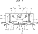
- a sectional view of an indoor unit of a conventional air conditioner is shown in Fig. 7 .
- the indoor unit is configured from a decorative panel 101 and a housing 102 connected to the decorative panel 101.
- the decorative panel 101 includes a suction grill 103 in the center.
- An outlet 105 including a wind directing plate 104 is disposed around the decorative panel 101.
- a centrifugal fan 121 consisting of a motor 106 and a fan member 107 connected to a shaft 120 of the motor 106 is set in the housing 102.
- the motor 106 is operated, whereby the fan member 107 rotates.
- the indoor air is sucked into a suction port 112 of the fan member 107 through the suction grill 103, a filter 116 set in the suction grill 103, and a bell mouth 110 set in the housing 102 and is discharged from a discharge port 113 of the fan member 107 as indicated by an arrow 118.
- An indoor heat exchanger 108 is disposed to surround the centrifugal fan 121.
- the air discharged from the fan member 107 is subjected to heat exchange in the indoor heat exchanger 108 and thereafter blown out into a room from the outlet 105 as indicated by an arrow 117.
- a drain pan 109 for receiving dew condensation water caused in the indoor heat exchanger 108 during cooling is set below the indoor heat exchanger 108.
- the suction grill 103 is detachable from the decorative panel 101 together with the filter 116. This structure makes it easy to perform cleaning of the filter 116.
- An electrical component box 111 in which a not-shown control board for controlling the operation of the indoor unit is housed, is set on the lower surface of the bell mouth 110.
- This structure makes it possible to easily perform maintenance of the electrical component box 111 by opening the suction grill 103.
- the bell mouth 110 is attached to an inner circumferential part of the drain pan 109 from below. This structure makes it possible to easily perform maintenance such as replacement of the fan member 107 and the motor 106 by opening the suction grill 103 and detaching the bell mouth 110.
- Fig. 8 shows a sectional view of the centrifugal fan 121 taken along a plane including a rotating shaft.
- a vibration prevention member 126 in which a rubber material 125 is joined by vulcanized adhesion between an inner cylinder 123 made of metal and an outer cylinder 124 made of metal, is attached to the center of the fan member 107.
- the inner cylinder is fit in the shaft 120 of the motor 106.
- a nut 127 By tightening a nut 127 over a screw provided at the distal end of the shaft 120, the motor 106 and the fan member 107 are fixed.
- Fig. 9 is a diagram of the vibration prevention member 126 viewed from the direction of the suction port 112 of the fan member.
- Both of a joining section of the inner cylinder 123 and the rubber material 125 and a joining section of the outer cylinder 124 and the rubber material 125 are circular.
- a turning force is transmitted to the fan member 107 via the vibration prevention member 126.
- An electromagnetic exciting force generated by the motor 106 is absorbed and attenuated by the rubber material 125 to be prevented from being transmitted to the fan member 107. Occurrence of electromagnetic sound is suppressed.
- the turning force received by the vibration prevention member 126 acts as shearing stress in a rotating direction on adhesion interfaces between the inner cylinder 123 and the rubber material 125 and between the outer cylinder 124 and the rubber material 125.
- JP-A-11-62891 a large number of concaves and convexes extending in the axial direction are formed at a predetermined interval in the circumferential direction on the outer circumferential surface of the inner cylinder of the vibration prevention member. Consequently, a part of torque in the rotating direction acts as stress in a direction for compressing rubber. Therefore, it is possible to reduce stress in a shearing direction.
- Patent Literature 1 JP-A-11-62891
- a problem to be solved by the present invention is to, in a fan consisting of a fan member including a vibration prevention member and a motor, reduce shearing stress to an adhesion interface between a vibration prevention material and metal, reduce excessive stress due to stress concentration, and improve reliability of the vibration prevention member.
- a fan of the present invention includes: a fan member; a motor that drives to rotate the fan member; and a rotating shaft that is connected to the fan member via a vibration prevention member and transmits a turning force of the motor to the fan member.
- the vibration prevention member is an elastic member that connects an inner cylinder made of metal included in the rotating shaft and an outer cylinder made of metal included in the fan member. At least one of an outer circumferential section of the inner cylinder and an inner circumferential section of the outer cylinder is configured as a polygon when viewed from the rotating shaft direction.
- a fan consisting of a fan member including a vibration prevention member and a motor, it is possible to reduce shearing stress to an adhesion interface between a vibration prevention material and metal and reduce excessive stress due to stress concentration.
- a fan of the present invention includes: a fan member; a motor that drives to rotate the fan member; and a rotating shaft that is connected to the fan via a vibration prevention member and transmits a turning force of the motor to the fan.
- the vibration prevention member is an elastic member that connects an inner cylinder made of metal included in the rotating shaft and an outer cylinder made of metal included in the fan member. At least one of an outer circumferential section of the inner cylinder and an inner circumferential section of the outer cylinder is configured as a polygon when viewed from the rotating shaft direction. According to the present invention, a turning force received by the vibration prevention member acts as compression stress on an adhesion interface between a vibration prevention material and metal. Therefore, it is possible to reduce shearing stress on the adhesion interface between the vibration prevention material and the metal and reduce excessive stress due to stress concentration.
- An air conditioner in this embodiment includes a compressor that compresses a refrigerant, an indoor heat exchanger that causes the refrigerant and the indoor air to perform heat exchange, an indoor fan that blows the air to the indoor heat exchanger, a decompression device that decompresses the refrigerant, an outdoor heat exchanger that causes the refrigerant and the outdoor air to perform heat exchange, and an outdoor fan that blows the air to the outdoor heat exchanger.
- a fan in this embodiment explained below is applied to at least the indoor fan or the outdoor fan.
- Fig. 2 is a sectional view showing an indoor unit of the air conditioner.
- the indoor unit is configured from a decorative panel 31 and a housing 32 connected to the decorative panel 31.
- the decorative panel 31 includes a suction grill 33 in the center.
- An outlet 35 including a wind directing plate 34 is disposed around the decorative panel 31.
- a centrifugal fan 5 including a motor 6 and a fan member 8 connected to a shaft 7 of the motor 6 is set in the housing 32.
- a vibration prevention member 1 is provided in the center of the fan member 8.
- the shaft 7 of the motor 6 and the fan member 8 are connected via the vibration prevention member 1.
- the motor 6 is operated, whereby the fan member 8 rotates. As a result, as indicated by an arrow 45 in Fig.
- the indoor air is sucked into a suction port 9 of the fan member 8 through the suction grill 33, a filter 36 set in the suction grill 33, and a bell mouth 37 set in the housing 32.
- the indoor air is discharged from a discharge port 10 of the fan member 8 as indicated by an arrow 48.
- An indoor heat exchanger 38 is disposed to surround the centrifugal fan 5.
- the air discharged from the fan member 8 is subjected to heat exchange in the indoor heat exchanger 38 and thereafter blown out into a room from the outlet 35 as indicated by an arrow 47.
- a drain pan 39 for receiving dew concentration water caused in the indoor heat exchanger 38 during cooling is set below the indoor heat exchanger 38.
- the suction grill 33 is detachable from the decorative panel 31 together with the filter 36. This structure makes it easy to perform cleaning of the filter 36.
- An electrical component box 40 in which a not-shown control board for controlling the operation of the indoor unit is housed, is set on the lower surface of the bell mouth 37. This structure makes it possible to easily perform maintenance of the electrical component box 40 by opening the suction grill 33.
- the bell mouth 37 is attached to an inner circumference section of the drain pan 39 from below. This structure makes it possible to easily perform maintenance such as replacement of the fan member 8 and the motor 6 as well by opening the suction grill 33 and detaching the bell mouth 37.
- Fig. 1 is a plan view of the vibration prevention member 1 viewed from the direction of the suction port 7 of the fan member 6.
- an elastic member (a rubber material 4) is joined by vulcanized adhesion between an inner cylinder 2 made of metal and an outer cylinder 3 made of metal.
- a joining section of the inner cylinder 2 made of metal and the rubber material 4 and a joining section of the outer cylinder 3 made of metal and the rubber material 4 are formed as an octagon.
- the shaft 9 of the motor 8 rotates, a turning force is transmitted to the fan member 6 via the vibration prevention member 1.
- An electromagnetic exciting force generated by the motor 8 is absorbed and attenuated by the rubber material 4 to be prevented from being transmitted to the fan member 6.
- Fig. 3 is a graph showing calculation values of stress near vertices in the case in which the number of vertices of a polygon of the joining section of the inner cylinder 2 and the rubber material 4 is changed.
- both of the joining section of the inner cylinder 2 and the rubber material 4 and the joining section of the outer cylinder 3 and the rubber material 4 are octagonal.
- Fig. 4 is a plan view of a vibration prevention member 11 of a fan viewed from the direction of a suction port of a fan member.
- the vibration prevention member 11 is configured by joining, with vulcanized adhesion, a rubber material 14 between an inner cylinder 12 made of metal and an outer cylinder 13 made of metal.
- both of a joining section of the inner cylinder 12 and the rubber material 14 and a joining section of the outer cylinder 13 and the rubber material 14 are formed in octagonal similar shapes.
- the vibration prevention member 11 is configured such that one vertex "a" of a polygon, which is the outer circumference of the inner cylinder 12, one vertex A of a polygon, which is the inner circumference of the outer cylinder 13, and a center point O of the polygons are aligned in this order.
- the outer circumference of the inner cylinder 12 and the inner circumference of the outer cylinder 13 are formed as similar octagons. Therefore, the other vertices of the outer circumference are also aligned with any vertices and the center point O of the polygons.
- a change in the thickness in the radial direction of the rubber material 14 decreases.
- a vibration prevention effect of an elastic material such as rubber is affected by thickness. The vibration prevention effect decreases when the thickness is small.
- the change in the thickness in the radial direction is large, it is likely that a portion where the thickness is small is formed and the vibration prevention effect decreases.
- the change in the thickness can be reduced, it is possible to suppress the decrease in the vibration prevention effect.
- FIG. 5 is a sectional view of a vibration prevention member 15 of a fan taken along a plane including a rotating shaft of a fan member.
- the vibration prevention member 15 is configured by joining, with vulcanized adhesion, a rubber material 18 between an inner cylinder 16 made of metal and an outer cylinder 17 made of metal.
- convex shapes 19 and 20 projecting toward the rubber material 18 side are provided in the centers in the axial direction of the outer circumferential section and the inner circumferential section.
- a suction port is provided vertically downward
- downward gravity is always applied to the fan member. If the rubber material 18 and the inner cylinder 16 or the outer cylinder 17 are disjoined because of an adhesion failure or the like, the fan member drops.
- the rubber material 18 can be supported by the convex shapes 19 and 20 in the centers, it is possible to prevent the fan member from dropping.
- the positions of the convex shapes 19 and 20 do not have to be the centers in the axial direction.
- the convex shapes 19 and 20 may be provided in different positions in the axial direction in the inner cylinder 16 and the outer cylinder 17.
- the vibration prevention member becomes symmetrical in the up-down direction. Workability is improved because it is unnecessary to take into account the up-down direction during manufacturing of the fan member.
- a convex shape may be provided in only one of the inner cylinder 16 and the outer cylinder 17. If an inner cylinder and an outer cylinder are manufactured by die-cast, it is possible to reduce man-hour of cutting and reduce cost. Further, the convex shape in this embodiment may be changed to a concave shape formed by recessing the inner cylinder or the outer cylinder in the opposite direction of the rubber material.
- FIG. 6 is a sectional view of a vibration prevention member 21 of a fan taken along a plane including a rotating shaft of a fan member.
- the vibration prevention member 15 is configured by joining, with vulcanized adhesion, the rubber material 18 between the inner cylinder 16 made of metal and the outer cylinder 17 made of metal.
- a concave shape 25 recessed in the opposite direction of a rubber material 24 is provided in an outer circumferential section of the inner cylinder 22 and a convex shape 26 projecting toward the rubber material 24 is provided in an inner circumferential section of the outer cylinder 23.
- the concave shape 25 of the inner cylinder 22 and the convex shape 26 of the outer cylinder 23 are provided in the same position in the axial direction of the vibration prevention member 21.
- the rubber material 24 and the inner cylinder 22 or the outer cylinder 23 are disjoined because of an adhesion failure or the like, the rubber material 24 can be supported by the concave shape 25 of the inner cylinder 22 or the convex shape 26 of the outer cylinder 23.
- the thickness in the radial direction of the rubber material 24 can be fixed over the entire length in the axial direction of the vibration prevention member 21. Therefore, it is possible to suppress a decrease in vibration reduction of the vibration prevention member 21. Note that the same effect can be obtained even if the concave shape 25 is formed in a convex shape and the convex shape 26 is formed in a concave shape.
- the rubber material is used in the vibration prevention member.
- an elastic body such as elastomer can be used.
- the fan is the centrifugal fan including the centrifugal fan member.
- the present invention can also be applied to fans of other forms such as an axial fan and a multi-blade fan. Further, in the embodiments, the example is explained in which the fan of the present invention is applied to the indoor unit of the ceiling embedded cassette type. However, the present invention can also be applied to indoor units of other forms and outdoor units of an upper blowing type, a lateral blowing type, and the like.
Landscapes
- Engineering & Computer Science (AREA)
- Mechanical Engineering (AREA)
- General Engineering & Computer Science (AREA)
- Chemical & Material Sciences (AREA)
- Combustion & Propulsion (AREA)
- Structures Of Non-Positive Displacement Pumps (AREA)
- Air-Conditioning Room Units, And Self-Contained Units In General (AREA)
- Other Air-Conditioning Systems (AREA)
Abstract
Description
- The present invention relates to a fan in which a motor and a fan member are fastened via a vibration prevention member and an air conditioner including the fan.
- An air conditioner includes a refrigeration cycle configured by sequentially disposing, in a refrigerant circulation channel in which a refrigerant is enclosed, a compressor that compresses the refrigerant, an indoor heat exchanger that causes the refrigerant and the indoor air to perform heat exchange, an expansion valve that decompresses the refrigerant, and an outdoor heat exchanger that causes the refrigerant and the outdoor air to perform heat exchange. The outdoor heat exchanger is housed in a housing of an outdoor unit together with a fan that sends the air to the outdoor heat exchanger. The indoor heat exchanger is housed in a housing of an indoor unit together with a fan that sends the indoor air to the indoor heat exchanger.
- As a form of the outdoor unit, there are, for example, an upper blowing type for blowing the air after the heat exchange from an upper part of the housing and a lateral blowing type for blowing the air after the heat exchange from the front surface of the housing. As the indoor unit, there are various forms according to installation places. In recent years, in particular, in the business field, a ceiling embedded cassette type for embedding a housing in the ceiling and performing suction and blowout of the air via a decorative panel set on the ceiling surface is mainly used. A sectional view of an indoor unit of a conventional air conditioner is shown in
Fig. 7 . The indoor unit is configured from adecorative panel 101 and ahousing 102 connected to thedecorative panel 101. Thedecorative panel 101 includes asuction grill 103 in the center. Anoutlet 105 including awind directing plate 104 is disposed around thedecorative panel 101. Acentrifugal fan 121 consisting of amotor 106 and afan member 107 connected to ashaft 120 of themotor 106 is set in thehousing 102. Themotor 106 is operated, whereby thefan member 107 rotates. As indicated by anarrow 115 inFig. 7 , the indoor air is sucked into asuction port 112 of thefan member 107 through thesuction grill 103, afilter 116 set in thesuction grill 103, and abell mouth 110 set in thehousing 102 and is discharged from adischarge port 113 of thefan member 107 as indicated by anarrow 118. Anindoor heat exchanger 108 is disposed to surround thecentrifugal fan 121. The air discharged from thefan member 107 is subjected to heat exchange in theindoor heat exchanger 108 and thereafter blown out into a room from theoutlet 105 as indicated by anarrow 117. Adrain pan 109 for receiving dew condensation water caused in theindoor heat exchanger 108 during cooling is set below theindoor heat exchanger 108. Thesuction grill 103 is detachable from thedecorative panel 101 together with thefilter 116. This structure makes it easy to perform cleaning of thefilter 116. Anelectrical component box 111, in which a not-shown control board for controlling the operation of the indoor unit is housed, is set on the lower surface of thebell mouth 110. This structure makes it possible to easily perform maintenance of theelectrical component box 111 by opening thesuction grill 103. Thebell mouth 110 is attached to an inner circumferential part of thedrain pan 109 from below. This structure makes it possible to easily perform maintenance such as replacement of thefan member 107 and themotor 106 by opening thesuction grill 103 and detaching thebell mouth 110. -
Fig. 8 shows a sectional view of thecentrifugal fan 121 taken along a plane including a rotating shaft. Avibration prevention member 126, in which arubber material 125 is joined by vulcanized adhesion between aninner cylinder 123 made of metal and anouter cylinder 124 made of metal, is attached to the center of thefan member 107. The inner cylinder is fit in theshaft 120 of themotor 106. By tightening anut 127 over a screw provided at the distal end of theshaft 120, themotor 106 and thefan member 107 are fixed.Fig. 9 is a diagram of thevibration prevention member 126 viewed from the direction of thesuction port 112 of the fan member. Both of a joining section of theinner cylinder 123 and therubber material 125 and a joining section of theouter cylinder 124 and therubber material 125 are circular. When theshaft 120 of themotor 106 rotates, a turning force is transmitted to thefan member 107 via thevibration prevention member 126. An electromagnetic exciting force generated by themotor 106 is absorbed and attenuated by therubber material 125 to be prevented from being transmitted to thefan member 107. Occurrence of electromagnetic sound is suppressed. At this point, the turning force received by thevibration prevention member 126 acts as shearing stress in a rotating direction on adhesion interfaces between theinner cylinder 123 and therubber material 125 and between theouter cylinder 124 and therubber material 125. Further, downward shearing stress by the own weight of the fan always acts on the adhesion interfaces. Therefore, it is necessary to sufficiently secure shearing strength of the adhesion interfaces between theinner cylinder 123 and therubber material 125 and between theouter cylinder 124 and therubber material 125. However, in order to sufficiently secure the shearing strength, it is necessary to appropriately perform surface treatment of an outer circumferential section of theinner cylinder 123 or an inner circumferential section of theouter cylinder 124. Therefore, manufacturing cost is increased. - On the other hand, for example, in
JP-A-11-62891 - Patent Literature 1:
JP-A-11-62891 - However, when the concaves and convexes are provided on the adhesion interface, stress concentration occurs in corner portions of the concaves and convexes. In particular, since large tightening torque acts during fan attachment, there is a risk that a crack is caused in the rubber starting from a stress concentrated portion. It is likely to cause imbalance of the fan and an increase in vibration.
- A problem to be solved by the present invention is to, in a fan consisting of a fan member including a vibration prevention member and a motor, reduce shearing stress to an adhesion interface between a vibration prevention material and metal, reduce excessive stress due to stress concentration, and improve reliability of the vibration prevention member.
- A fan of the present invention includes: a fan member; a motor that drives to rotate the fan member; and a rotating shaft that is connected to the fan member via a vibration prevention member and transmits a turning force of the motor to the fan member. The vibration prevention member is an elastic member that connects an inner cylinder made of metal included in the rotating shaft and an outer cylinder made of metal included in the fan member. At least one of an outer circumferential section of the inner cylinder and an inner circumferential section of the outer cylinder is configured as a polygon when viewed from the rotating shaft direction.
- According to the present invention, in a fan consisting of a fan member including a vibration prevention member and a motor, it is possible to reduce shearing stress to an adhesion interface between a vibration prevention material and metal and reduce excessive stress due to stress concentration.
-
- [
Fig. 1] Fig. 1 is a plan view of a vibration prevention member in a first embodiment viewed from the direction of a suction port of a fan member. - [
Fig. 2] Fig. 2 is a sectional view showing an indoor unit of an air conditioner in the first embodiment. - [
Fig. 3] Fig. 3 is a graph showing a relation between the number of vertices of a polygon of a joining section of an inner cylinder and a rubber material and stress at the vertices. - [
Fig. 4] Fig. 4 is a plan view of a vibration prevention member in a second embodiment viewed from the direction of a suction port of a fan member. - [
Fig. 5] Fig. 5 is a sectional view of a vibration prevention member of a fan in a third embodiment taken along a plane including a rotating shaft of a fan member. - [
Fig. 6] Fig. 6 is a sectional view of a vibration prevention member of a fan in a fourth embodiment taken along a plane including a rotating shaft of a fan member. - [
Fig. 7] Fig. 7 is a sectional view showing an example of an indoor unit of a conventional air conditioner. - [
Fig. 8] Fig. 8 is a sectional view of a conventional centrifugal fan taken along a plane including a rotating shaft. - [
Fig. 9] Fig. 9 is a plan view of a conventional vibration prevention member viewed from the direction of a suction port of the fan member. - A fan of the present invention includes: a fan member; a motor that drives to rotate the fan member; and a rotating shaft that is connected to the fan via a vibration prevention member and transmits a turning force of the motor to the fan. The vibration prevention member is an elastic member that connects an inner cylinder made of metal included in the rotating shaft and an outer cylinder made of metal included in the fan member. At least one of an outer circumferential section of the inner cylinder and an inner circumferential section of the outer cylinder is configured as a polygon when viewed from the rotating shaft direction. According to the present invention, a turning force received by the vibration prevention member acts as compression stress on an adhesion interface between a vibration prevention material and metal. Therefore, it is possible to reduce shearing stress on the adhesion interface between the vibration prevention material and the metal and reduce excessive stress due to stress concentration.
- A first embodiment of the present invention is explained with reference to
Fig. 1, Fig. 2 , andFig. 3 . An air conditioner in this embodiment includes a compressor that compresses a refrigerant, an indoor heat exchanger that causes the refrigerant and the indoor air to perform heat exchange, an indoor fan that blows the air to the indoor heat exchanger, a decompression device that decompresses the refrigerant, an outdoor heat exchanger that causes the refrigerant and the outdoor air to perform heat exchange, and an outdoor fan that blows the air to the outdoor heat exchanger. A fan in this embodiment explained below is applied to at least the indoor fan or the outdoor fan. -
Fig. 2 is a sectional view showing an indoor unit of the air conditioner. The indoor unit is configured from adecorative panel 31 and ahousing 32 connected to thedecorative panel 31. Thedecorative panel 31 includes asuction grill 33 in the center. An outlet 35 including awind directing plate 34 is disposed around thedecorative panel 31. Acentrifugal fan 5 including amotor 6 and afan member 8 connected to ashaft 7 of themotor 6 is set in thehousing 32. Avibration prevention member 1 is provided in the center of thefan member 8. Theshaft 7 of themotor 6 and thefan member 8 are connected via thevibration prevention member 1. Themotor 6 is operated, whereby thefan member 8 rotates. As a result, as indicated by anarrow 45 inFig. 2 , the indoor air is sucked into a suction port 9 of thefan member 8 through thesuction grill 33, afilter 36 set in thesuction grill 33, and abell mouth 37 set in thehousing 32. The indoor air is discharged from adischarge port 10 of thefan member 8 as indicated by anarrow 48. Anindoor heat exchanger 38 is disposed to surround thecentrifugal fan 5. The air discharged from thefan member 8 is subjected to heat exchange in theindoor heat exchanger 38 and thereafter blown out into a room from the outlet 35 as indicated by anarrow 47. - A
drain pan 39 for receiving dew concentration water caused in theindoor heat exchanger 38 during cooling is set below theindoor heat exchanger 38. Thesuction grill 33 is detachable from thedecorative panel 31 together with thefilter 36. This structure makes it easy to perform cleaning of thefilter 36. Anelectrical component box 40, in which a not-shown control board for controlling the operation of the indoor unit is housed, is set on the lower surface of thebell mouth 37. This structure makes it possible to easily perform maintenance of theelectrical component box 40 by opening thesuction grill 33. Thebell mouth 37 is attached to an inner circumference section of thedrain pan 39 from below. This structure makes it possible to easily perform maintenance such as replacement of thefan member 8 and themotor 6 as well by opening thesuction grill 33 and detaching thebell mouth 37. -
Fig. 1 is a plan view of thevibration prevention member 1 viewed from the direction of thesuction port 7 of thefan member 6. In thevibration prevention member 1, an elastic member (a rubber material 4) is joined by vulcanized adhesion between aninner cylinder 2 made of metal and anouter cylinder 3 made of metal. In this embodiment, a joining section of theinner cylinder 2 made of metal and therubber material 4 and a joining section of theouter cylinder 3 made of metal and therubber material 4 are formed as an octagon. When the shaft 9 of themotor 8 rotates, a turning force is transmitted to thefan member 6 via thevibration prevention member 1. An electromagnetic exciting force generated by themotor 8 is absorbed and attenuated by therubber material 4 to be prevented from being transmitted to thefan member 6. Occurrence of electromagnetic sound is suppressed. Since both of the joining section of theinner cylinder 2 and therubber material 4 and the joining section of theouter cylinder 3 and therubber material 4 are octagonal, on adhesive interfaces between theinner cylinder 2 and therubber material 4 and between theouter cylinder 3 and therubber material 4, a part of the turning force received by thevibration prevention member 1 acts as a compression stress against a joining surface of theinner cylinder 2 or theouter cylinder 3. Therefore, it is possible to reduce shearing stress compared with when the joining section is circular. Even if an adhesion failure occurs, it is possible to receive the turning force. Therefore, it is possible to transmit the turning force of the fan member. -
Fig. 3 is a graph showing calculation values of stress near vertices in the case in which the number of vertices of a polygon of the joining section of theinner cylinder 2 and therubber material 4 is changed. By forming the joining section as the polygon, it is possible to reduce shearing stress in the portions of the sides of the polygon. However, stress concentration is sometimes caused in the portions of the vertices of the polygon. It is seen fromFig. 3 that, whereas the stress suddenly increases when the number of the vertices of the polygon decrease, the stress hardly changes when the number of vertices of the polygon is equal to or larger than sixteen. When the vertices of the polygon increase, an area capable of receiving the turning force as the compression stress decreases. Therefore, it is desirable to reduce the number of the vertices in a range in which reliability can be secured. Therefore, it is desirable to select the number of the vertices in a range of 6 to 16. - Note that, in this embodiment, both of the joining section of the
inner cylinder 2 and therubber material 4 and the joining section of theouter cylinder 3 and therubber material 4 are octagonal. However, for example, for convenience in manufacturing, it is also possible to form only one of the joining sections as a polygon and form the other as a circle as in the past. - A second embodiment of the present invention is explained with reference to
Fig. 4. Fig. 4 is a plan view of avibration prevention member 11 of a fan viewed from the direction of a suction port of a fan member. As in the first embodiment, thevibration prevention member 11 is configured by joining, with vulcanized adhesion, arubber material 14 between aninner cylinder 12 made of metal and anouter cylinder 13 made of metal. - Both of a joining section of the
inner cylinder 12 and therubber material 14 and a joining section of theouter cylinder 13 and therubber material 14 are formed in octagonal similar shapes. In this embodiment, thevibration prevention member 11 is configured such that one vertex "a" of a polygon, which is the outer circumference of theinner cylinder 12, one vertex A of a polygon, which is the inner circumference of theouter cylinder 13, and a center point O of the polygons are aligned in this order. The outer circumference of theinner cylinder 12 and the inner circumference of theouter cylinder 13 are formed as similar octagons. Therefore, the other vertices of the outer circumference are also aligned with any vertices and the center point O of the polygons. Consequently, compared with the first embodiment, a change in the thickness in the radial direction of therubber material 14 decreases. A vibration prevention effect of an elastic material such as rubber is affected by thickness. The vibration prevention effect decreases when the thickness is small. When the change in the thickness in the radial direction is large, it is likely that a portion where the thickness is small is formed and the vibration prevention effect decreases. In this embodiment, since the change in the thickness can be reduced, it is possible to suppress the decrease in the vibration prevention effect. - A third embodiment of the present invention is explained with reference to
Fig. 5. Fig. 5 is a sectional view of avibration prevention member 15 of a fan taken along a plane including a rotating shaft of a fan member. As in the embodiments explained above, thevibration prevention member 15 is configured by joining, with vulcanized adhesion, arubber material 18 between aninner cylinder 16 made of metal and anouter cylinder 17 made of metal. - In this embodiment, in an outer circumferential section of the
inner cylinder 16 and an inner circumferential section of theouter cylinder 17,convex shapes rubber material 18 side are provided in the centers in the axial direction of the outer circumferential section and the inner circumferential section. In a fan member in which a suction port is provided vertically downward, downward gravity is always applied to the fan member. If therubber material 18 and theinner cylinder 16 or theouter cylinder 17 are disjoined because of an adhesion failure or the like, the fan member drops. However, in the fan member in this embodiment, since therubber material 18 can be supported by theconvex shapes - Note that the positions of the
convex shapes convex shapes inner cylinder 16 and theouter cylinder 17. By providing theconvex shapes inner cylinder 16 and theouter cylinder 17. If an inner cylinder and an outer cylinder are manufactured by die-cast, it is possible to reduce man-hour of cutting and reduce cost. Further, the convex shape in this embodiment may be changed to a concave shape formed by recessing the inner cylinder or the outer cylinder in the opposite direction of the rubber material. - A fourth embodiment of the present invention is explained with reference to
Fig. 6. Fig. 6 is a sectional view of avibration prevention member 21 of a fan taken along a plane including a rotating shaft of a fan member. As in the embodiments explained above, thevibration prevention member 15 is configured by joining, with vulcanized adhesion, therubber material 18 between theinner cylinder 16 made of metal and theouter cylinder 17 made of metal. - In this embodiment, a
concave shape 25 recessed in the opposite direction of arubber material 24 is provided in an outer circumferential section of theinner cylinder 22 and aconvex shape 26 projecting toward therubber material 24 is provided in an inner circumferential section of theouter cylinder 23. Theconcave shape 25 of theinner cylinder 22 and theconvex shape 26 of theouter cylinder 23 are provided in the same position in the axial direction of thevibration prevention member 21. In the vibration prevention member in the third embodiment, it is likely that the thickness of the rubber material decreases in the convex shape section and vibration prevention performance is deteriorated. On the other hand, in this embodiment, if therubber material 24 and theinner cylinder 22 or theouter cylinder 23 are disjoined because of an adhesion failure or the like, therubber material 24 can be supported by theconcave shape 25 of theinner cylinder 22 or theconvex shape 26 of theouter cylinder 23. In addition, the thickness in the radial direction of therubber material 24 can be fixed over the entire length in the axial direction of thevibration prevention member 21. Therefore, it is possible to suppress a decrease in vibration reduction of thevibration prevention member 21. Note that the same effect can be obtained even if theconcave shape 25 is formed in a convex shape and theconvex shape 26 is formed in a concave shape. - In the embodiments, the rubber material is used in the vibration prevention member. However, an elastic body such as elastomer can be used. The fan is the centrifugal fan including the centrifugal fan member. However, the present invention can also be applied to fans of other forms such as an axial fan and a multi-blade fan. Further, in the embodiments, the example is explained in which the fan of the present invention is applied to the indoor unit of the ceiling embedded cassette type. However, the present invention can also be applied to indoor units of other forms and outdoor units of an upper blowing type, a lateral blowing type, and the like.
-
- 1, 11, 15, 21, 126
- vibration prevention member
- 2, 12, 16, 22, 123
- inner cylinder
- 3, 13, 17, 23, 124
- outer cylinder
- 4, 14, 18, 24, 125
- rubber material
- 5, 121
- centrifugal fan
- 6, 106
- motor
- 7, 120
- shaft
- 8, 107
- fan member
- 9, 112
- suction port of the fan member
Claims (11)
- A fan comprising:a fan member;a motor that drives to rotate the fan member; anda rotating shaft that is connected to the fan member via a vibration prevention member and transmits a turning force of the motor to the fan member, whereinthe vibration prevention member is an elastic member that connects an inner cylinder made of metal included in the rotating shaft and an outer cylinder made of metal included in the fan member, andat least one of an outer circumferential section of the inner cylinder and an inner circumferential section of the outer cylinder is configured as a polygon when viewed from the rotating shaft direction.
- The fan according to claim 1, wherein the polygon is in a range of a hexagon to a hexadecagon.
- The fan according to claim 1 or 2, wherein
the outer circumferential section and the inner circumferential section are similar polygons when viewed from an axial direction of the motor, and
one vertex of the polygon of the outer circumferential section, one vertex of the polygon of the inner circumferential section, and a center point of the polygon of the inner circumferential section are aligned in this order. - The fan according to any one of claims 1 to 3, wherein a convex shape projecting toward the vibration prevention member is formed in at least one of the outer circumferential section and the inner circumferential section.
- The fan according to claim 4, wherein the convex shape is formed in a center in an axial direction of the outer circumferential section or the inner circumferential section.
- The fan according to any one of claims 1 to 3, wherein a concave shape recessed toward an opposite direction of the vibration prevention member is formed in at least one of the outer circumferential section and the inner circumferential section.
- The fan according to claim 6, wherein the concave shape is formed in a center in an axial direction of the outer circumferential section or the inner circumferential section.
- The fan according to any one of claims 1 to 3, wherein
a convex shape projecting toward the vibration prevention member is formed in the outer circumferential section, and
a concave shape recessed toward an opposite direction of the vibration prevention member is formed in the inner circumferential section and in a position in an axial direction corresponding to the convex shape. - The fan according to any one of claims 1 to 3, wherein
a convex shape projecting toward the vibration prevention member is formed in the inner circumferential section, and
a concave shape recessed toward an opposite direction of the vibration prevention member is formed in the outer circumferential section and in a position in an axial direction corresponding to the convex shape. - The fan according to any one of claims 1 to 9, wherein the elastic member is rubber or elastomer.
- An air conditioner comprising:a compressor that compresses a refrigerant;an indoor heat exchanger that causes the refrigerant and indoor air to perform heat exchange;an indoor fan that blows the air to the indoor heat exchanger;a decompression device that decompresses the refrigerant;an outdoor heat exchanger that causes the refrigerant and outdoor air to perform heat exchange; andan outdoor fan that blows the air to the outdoor heat exchanger, whereinthe fan according to any one of claims 1 to 10 is used in at least the indoor fan or the outdoor fan.
Applications Claiming Priority (1)
| Application Number | Priority Date | Filing Date | Title |
|---|---|---|---|
| PCT/JP2014/069636 WO2016013096A1 (en) | 2014-07-25 | 2014-07-25 | Blower and air conditioning machine |
Publications (2)
| Publication Number | Publication Date |
|---|---|
| EP3173628A1 true EP3173628A1 (en) | 2017-05-31 |
| EP3173628A4 EP3173628A4 (en) | 2018-03-21 |
Family
ID=55162651
Family Applications (1)
| Application Number | Title | Priority Date | Filing Date |
|---|---|---|---|
| EP14898317.4A Withdrawn EP3173628A4 (en) | 2014-07-25 | 2014-07-25 | Blower and air conditioning machine |
Country Status (6)
| Country | Link |
|---|---|
| US (1) | US10533757B2 (en) |
| EP (1) | EP3173628A4 (en) |
| JP (1) | JPWO2016013096A1 (en) |
| CN (1) | CN106574629A (en) |
| TW (1) | TWI591260B (en) |
| WO (1) | WO2016013096A1 (en) |
Families Citing this family (4)
| Publication number | Priority date | Publication date | Assignee | Title |
|---|---|---|---|---|
| KR102466274B1 (en) * | 2017-04-28 | 2022-11-11 | 삼성전자주식회사 | Air conditioner |
| EP3643983B1 (en) * | 2017-06-23 | 2021-08-11 | Daikin Industries, Ltd. | Air conditioning indoor unit |
| CN109681449A (en) * | 2018-02-06 | 2019-04-26 | 全亿大科技(佛山)有限公司 | The electronic device of radiator fan and the application radiator fan |
| JP6991925B2 (en) | 2018-05-29 | 2022-01-13 | リンナイ株式会社 | Blower fan |
Family Cites Families (16)
| Publication number | Priority date | Publication date | Assignee | Title |
|---|---|---|---|---|
| US3480373A (en) * | 1966-11-01 | 1969-11-25 | Cooling Dev Ltd | Fans |
| SE7500297L (en) * | 1975-01-13 | 1976-07-14 | Skf Nova Ab | VIBRATION DAMPING COUPLING |
| DE3112146A1 (en) * | 1981-03-27 | 1982-10-07 | Ziehl-Abegg GmbH & Co KG, 7119 Künzelsau | Coupling for fan roller |
| JPS5879095U (en) * | 1981-11-24 | 1983-05-28 | 三菱電機株式会社 | Juan |
| JPH0510799U (en) * | 1991-07-16 | 1993-02-12 | エヌオーケー株式会社 | Bush for impeller |
| JPH10159792A (en) * | 1996-12-02 | 1998-06-16 | Mitsubishi Electric Corp | Blower |
| JP4008073B2 (en) * | 1997-08-08 | 2007-11-14 | 三菱重工業株式会社 | Turbofan and air conditioner equipped with the same |
| US5938405A (en) * | 1998-03-06 | 1999-08-17 | Coleman Machine, Inc. | Quick release engine cooling fan shaft |
| DE10060003A1 (en) * | 2000-12-02 | 2002-06-13 | Dietrich Denker | The coupling acts as a spring between rotary masses. |
| JP2002235804A (en) * | 2001-02-07 | 2002-08-23 | Sanko Gosei Ltd | Turbo fan having vibration insulation function |
| CN1215264C (en) | 2001-09-03 | 2005-08-17 | 三菱电机株式会社 | Antivibrating structure for blowing machine and air conditioner |
| JP2003269381A (en) * | 2002-03-13 | 2003-09-25 | Mitsubishi Electric Corp | Blower and fan support mechanism and air conditioner |
| JP2003286997A (en) | 2002-03-28 | 2003-10-10 | Sanyo Electric Co Ltd | Air blowing device |
| JP4928500B2 (en) * | 2008-05-15 | 2012-05-09 | 日清紡メカトロニクス株式会社 | Vibration isolator for blower fan and blower fan structure including the same |
| JP5574841B2 (en) * | 2010-06-18 | 2014-08-20 | 三菱重工業株式会社 | Turbofan and air conditioner using the same |
| KR101351093B1 (en) * | 2010-08-02 | 2014-01-14 | 삼성전자주식회사 | A Blowing Fan and Vibration Absorbing Boss thereof |
-
2014
- 2014-07-25 WO PCT/JP2014/069636 patent/WO2016013096A1/en not_active Ceased
- 2014-07-25 US US15/326,729 patent/US10533757B2/en active Active
- 2014-07-25 JP JP2016535598A patent/JPWO2016013096A1/en active Pending
- 2014-07-25 CN CN201480080832.7A patent/CN106574629A/en active Pending
- 2014-07-25 EP EP14898317.4A patent/EP3173628A4/en not_active Withdrawn
-
2015
- 2015-06-11 TW TW104118921A patent/TWI591260B/en active
Also Published As
| Publication number | Publication date |
|---|---|
| JPWO2016013096A1 (en) | 2017-04-27 |
| CN106574629A (en) | 2017-04-19 |
| US10533757B2 (en) | 2020-01-14 |
| TWI591260B (en) | 2017-07-11 |
| EP3173628A4 (en) | 2018-03-21 |
| US20170205083A1 (en) | 2017-07-20 |
| WO2016013096A1 (en) | 2016-01-28 |
| TW201615990A (en) | 2016-05-01 |
Similar Documents
| Publication | Publication Date | Title |
|---|---|---|
| EP2799720B1 (en) | Axial flow fan | |
| JP6767688B2 (en) | Indoor air conditioning system | |
| US10533757B2 (en) | Fan and air conditioner | |
| US11118597B2 (en) | Fan and indoor unit of air-conditioning apparatus provided with fan | |
| EP2333435A2 (en) | Bell-mouth structure of air blower | |
| US20150003992A1 (en) | Axial-flow fan | |
| US20190040873A1 (en) | Air-sending device and air-conditioning apparatus using the same | |
| WO2006129891A3 (en) | Outdoor unit for split type air-conditioner | |
| JP6292241B2 (en) | Centrifugal fan | |
| JP6000204B2 (en) | Heat pump heat source unit | |
| EP3225934A1 (en) | Indoor unit for air conditioner | |
| JPH1162891A (en) | Turbofan and air conditioner provided with the same | |
| AU2014260997B2 (en) | Decorative panel for air conditioner, and in-room unit | |
| JP5858851B2 (en) | Air conditioner indoor unit | |
| US20110284190A1 (en) | Centrifugal air blower and air conditioner | |
| JP6950660B2 (en) | Blower and air conditioner equipped with it | |
| EP3006856A2 (en) | Indoor unit and air conditioner | |
| US20180274800A1 (en) | Outdoor unit | |
| JP2014227865A (en) | Supporting structure for blower | |
| KR100512419B1 (en) | Fixed structure of driving motor in indoor unit of air conditioner | |
| JP2013108684A (en) | Indoor unit of air conditioner | |
| JP5484876B2 (en) | Blower and air conditioner | |
| KR20120035251A (en) | Blade of fan | |
| JP2010038016A (en) | Streamlining tool for propeller fan and outdoor unit for air-conditioning apparatus |
Legal Events
| Date | Code | Title | Description |
|---|---|---|---|
| STAA | Information on the status of an ep patent application or granted ep patent |
Free format text: STATUS: THE INTERNATIONAL PUBLICATION HAS BEEN MADE |
|
| PUAI | Public reference made under article 153(3) epc to a published international application that has entered the european phase |
Free format text: ORIGINAL CODE: 0009012 |
|
| STAA | Information on the status of an ep patent application or granted ep patent |
Free format text: STATUS: REQUEST FOR EXAMINATION WAS MADE |
|
| 17P | Request for examination filed |
Effective date: 20170227 |
|
| AK | Designated contracting states |
Kind code of ref document: A1 Designated state(s): AL AT BE BG CH CY CZ DE DK EE ES FI FR GB GR HR HU IE IS IT LI LT LU LV MC MK MT NL NO PL PT RO RS SE SI SK SM TR |
|
| AX | Request for extension of the european patent |
Extension state: BA ME |
|
| DAX | Request for extension of the european patent (deleted) | ||
| RIN1 | Information on inventor provided before grant (corrected) |
Inventor name: YONEYAMA, HIROYASU Inventor name: OBARA, HIDESHI Inventor name: YONEKURA, KOJI |
|
| RAP1 | Party data changed (applicant data changed or rights of an application transferred) |
Owner name: HITACHI-JOHNSON CONTROLS AIR CONDITIONING, INC. |
|
| A4 | Supplementary search report drawn up and despatched |
Effective date: 20180219 |
|
| RIC1 | Information provided on ipc code assigned before grant |
Ipc: F04D 29/28 20060101AFI20180213BHEP Ipc: F04D 25/08 20060101ALI20180213BHEP Ipc: F04D 29/66 20060101ALI20180213BHEP Ipc: F04D 29/26 20060101ALI20180213BHEP |
|
| GRAP | Despatch of communication of intention to grant a patent |
Free format text: ORIGINAL CODE: EPIDOSNIGR1 |
|
| STAA | Information on the status of an ep patent application or granted ep patent |
Free format text: STATUS: GRANT OF PATENT IS INTENDED |
|
| INTG | Intention to grant announced |
Effective date: 20200402 |
|
| STAA | Information on the status of an ep patent application or granted ep patent |
Free format text: STATUS: THE APPLICATION IS DEEMED TO BE WITHDRAWN |
|
| 18D | Application deemed to be withdrawn |
Effective date: 20200813 |